Embed Size (px)
Citation preview

co d
I c3 z w
I
k 5 111 8 a k
p:
z w m d w
5:
B X c3 H W X X E 0 p: E4
d (3 m .
S-75,171
1 -
osm
FROTH HEIGHT LEVEL SENSOR
BY
Joseph W. Glaser (USA) 2586 Windsor Court Union City, CA 94587
Leroy Holmes (USA) 11336 Roeding Road Denair, CA 95316
Ravindra S. Upadhye (USA) 916 Sherman Way Pleasanton, CA 94566
John G. Wilder (USA) 2211 Bueno Vista Ave Livermore, CA 94550
..
0- 0 (v

DISCLAIMER
Portions of this document may be illegible in electronic image products. Images are produced from the best available original document.
-1-
FROTH HEIGHT LEVEL SENSOR
5
The United States Government has rights in this invention pursuant to
Contract No. W-7405-ENG48 between the United States Department of Energy and
the University of California for the operation of Lawrence Livermore National
Laboratory.
BACKGROUND OF THE INVENTION
Field of the Invention
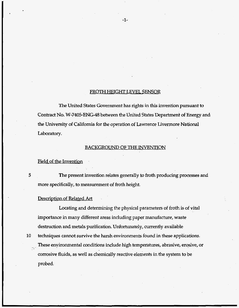
The present invention relates generally to froth producing processes and
more specifically, to measurement of froth height.
DescriDtion of Related Art
Locating and determining the physical parameters of froth is of vital
importance in many different areas including paper manufacture, waste
destruction and metals purification. Unfortunately, currently available
10 techniques cannot survive the harsh environments found in these applications.
.- . These environmental conditions include high temperatures, abrasive, erosive, or
corrosive fluids, as well as chemically reactive elements in the system to be
probed.
-2-
5
10
15
20
25
The Molten Salt Destruction (MSD) process is one example of a process
where it would be desirable to know if frothing occurs and if so, its height within
the process chamber. Oxidation of mixed waste can be accomplished in an
enclosed environment such as that found in the MSD process. The destruction of
potentially toxic organic compounds is completely contained within the process
chamber leaving the radioactive residue contained within the molten salt. As
the fuel and oxidant are brought together within the molten salt, the liquid tends
to bubble as the gases float upwards. The resultant froth and the height it attains
must be known. Should the level of the froth rise too high within the process
chamber, the froth would clog the hardware located at the top of the chamber
thereby degrading process performance and throughput.
Classical fosm height measuring techniques employing contact
sensors, such as conductivity probes, have a tendency to clog as a result of
deposit formation. In these environments, the diagnostic would require some
mechanism to allow periodic flushing to clean the probe. When used in such
areas as the pulp and paper industry, this cleaning mechanism is helpful but not
always completely successful.
Resistance tape sensors, which are activated by the hydrostatic
pressure near the surface of the liquid in which the gauge is submerged, has also
been used to measure the level of the froth interface on top of ore enrichment
columns. The froth level is a critical parameter in the enrichment process and
must be monitored to ensure proper process operation. The froth, however is
both hot and corrosive, necessitating the probe be placed in a protective envelope
which isolates the probe from the direct environment being measured.
Ultrasonic and radar based sensors have sensor temperature operating
limits. Since froth bubbles are not planar surfaces, beams scatter unpredictably

5
10
15
20
-3-
off bubble surfaces. This introduces unacceptably large errors when trying to use
these techniques to determine froth location.
US. Patent No. 2,511,649 is directed to a liquid level gauge to determine
the approximate level of a liquid in a pressurized tank. Tubes of various known
depths are inserted into the tank. In use, the valves in the head are successively
opened until adjoining valves are discovered, one of which allows gas to escape, and
the other of which allows liquid to escape.
U.S. Patent No. 4,393,705 is directed to a specific gravity level gauge.
U.S. Patent No. 3,250,122 is directed to a method for determining the interface level
in tankage of materials. U.S. Patent No. 3,664,365 is directed to a method and
apparatus for the automatic supervision of liquid limits in closed tanks. U.S. Patent
No. 4,567,761 is directed to a device for detecting variations in the height of the free
level of a liquid by use of a differential pressure gauge.
U.S. Patent No. 4,669,309 is directed to a tank contents gauge having
two pressure sensors to sense the liquid pressure at two tank positions at a
known vertical separation. U.S. Patent No. 5,005,408 is directed to a gas weights
compensation method for liquid depth gauging. U.S. Patent No. 5,073,253 is
directed to a froth level measurement which includes a float, a nozzle, and an
ultrasonic level detector.
Consequently, a need exists for a technique to more easily monitor the
location and/or presence of froth under certain problematic environmental
conditions.
.. .
-4-
SUMMARY OF THE INVENTION
It is an object of the present invention to provide a method and apparatus
for measurement of froth height, especially under adverse environmental
conditions.
The present invention utilizes the pressure differential existing between
5 process chamber ambient pressure and the froth pressure to determine the existence
of a froth and its location. A single sensor, comprised of a tube located near the
foaming liquid, another tube well away from the first, and a differential pressure
gauge between the two tubes, can be used to determine the existence of the foam in
the vicinity of the probe. In order to ensure stable operation, the tube located near
10 the foaming liquid has gas flowing through it. This gas flow keeps the tube clear of
foam and prevents clogging. Two sensors a known distance apart can be used to
locate the froth assuming a uniform froth density. Where froth density is not
constant, multiple sensors at differing heights with respect to each other, or a single
movable sensor, are used. Information derived using the multiple or movable sensor
yields unambiguous froth density and height data. 15
Thus, the present invention is inexpensive to operate, does not require a
large amount of operator training and can be used in a variety of fashions under
extreme conditions. As a single sensor, it can be used to determine the presence of
foam as a go/no-go diagnostic. Where the froth location varies over a limited range,
the dual sensor configuration will yield location and density information. Multiple
or movable sensors are used to determine both froth density and height.
20
-5-
5
10
15
20
BRIEF DESCRIPTION OF THE DRAWINGS
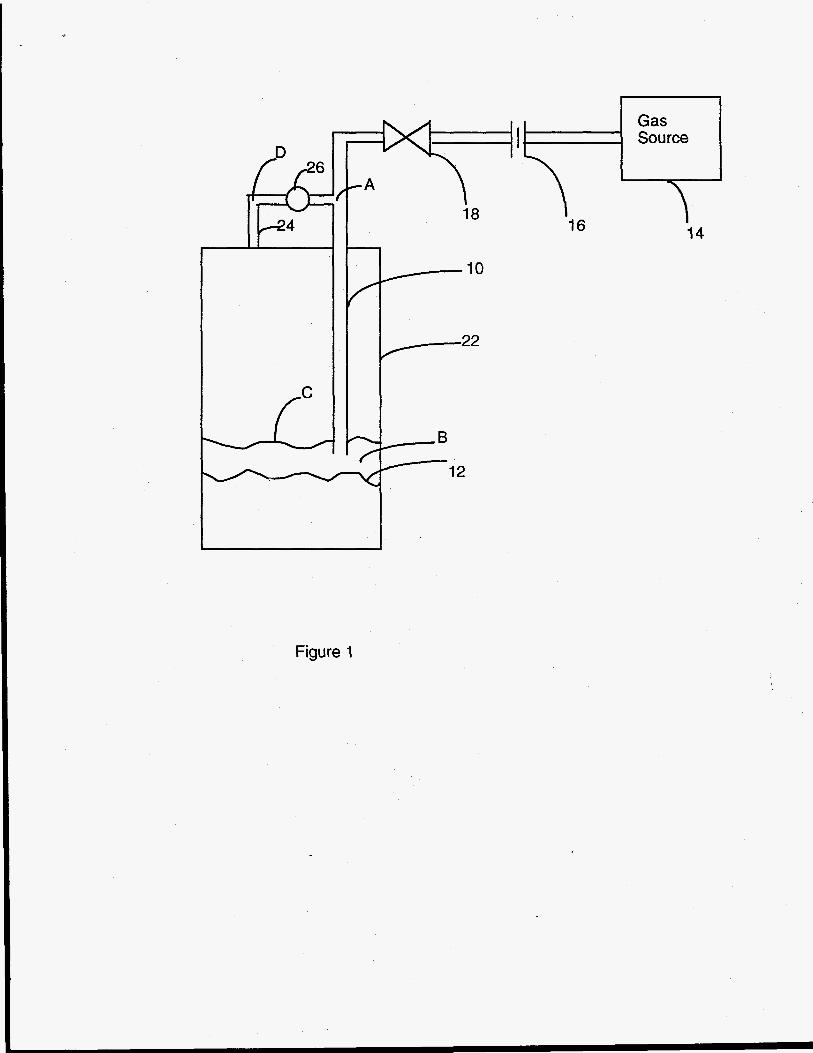
Figure 1 shows the basic design of the froth height level sensor.
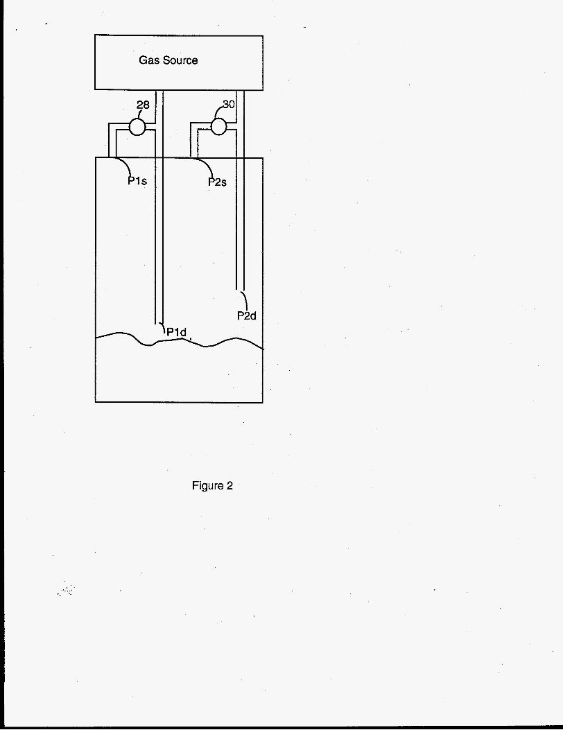
Figure 2 shows the “dual probe” froth height level sensor.
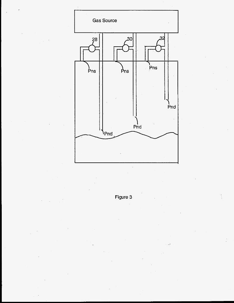
Figure 3 shows an embodiment of the multiple sensor probe.
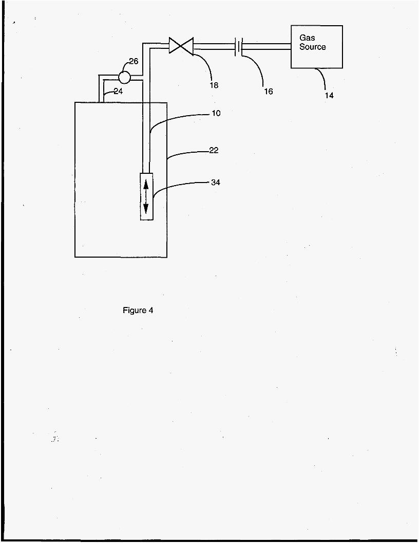
Figure 4 shows a moveable probe.
DETAILED DESCRIPTION OF THE INVENTION
One embodiment of the froth height measuring system is shown in
Figure 1. The arrangement shown in figure 1 is used to determine the presence
of foam, but not its actual location (go/no-go sensor). It consists of a gas injection
tube and a differential pressure monitor between the injection tube and the
reactor vessel. By initially positioning the injection tube 10 slightly above the
quiescent fluid surface 12 and slowly flowing gas from gas source 14 through
flow control orifice 16 and valve 18 through tube 10 to keep it free of froth once
processing begins, the foam height may be determined by comparing the
pressure difference between injection tube 10 and the vessel 22 at the static tube
24. The injection gas flow rate must be high enough to keep the tube free of foam
but low enough so that the system dynamic pressure drop is low. Differential
pressure gauge 26 is connected between tube 10 and tube 24.
Using point B (Fig. 1) as a vessel reference pressure, the pressure in the
injection tube at point A (in the absence of froth in the tube, and neglecting the
ktatic gas head) is
PA= PB + hL
where
-6-
5
15
20
PA is the pressure at point A;
PB is the pressure at point B; and
hL is the friction flow loss from A to B,
For low gas flow rates, hL may be neglected.
The pressure at point D in the vessel (fig l), may be written as:
where
10 C is the level of the foam surface;
PD is the pressure at point D;
Pg is the pressure at point B;
pf- is the density of the foam;
g is the acceleration due to gravity; and
dh is the incremental height.
The pressure difference between the reactor vessel and the injection tube
(pressure at point D minus pressure at point A) may be written as
(pressure at point A minus pressure at point D) may be written as
A)? = /B>fomg dh (3)
Or, in the case of a constant density foam (pftm= constant)
25
-7-
As may be seen, these assumptions result in a relationship where the
foam height AHfoam is proportional to the pressure difference measured
between the injection tube and the reactor vessel. This relationship between foam
height and pressure differential forms the basis for this invention. In the presence
of a froth (A-0), the sensor shown in figure 1 will respond, indicating the
presence of froth.
5
However, even though the pressure differential and the froth height are
related, it is not possible to determine the actual height without knowing froth
density since there are two unknowns in equation 4: froth density and froth
height. This problem is circumvented, for pf,, = constant, by measuring the
froth pressure at two different known elevations (figure 2). If AP = pf-gA H, h
10
15
20
is the height of the foam and AH = X, where X is the known elevation difference
between the two tubes; Pld and P2d (Figure 2).
AI? = PI - P2; and
Pi= Promg h; then
AP= PfoaIngX;
P1-P2 = pfmg X; and
PI-p2 =%x , therefore
The two probe configuration shown in figure 2 can therefore be used to
determine actual froth height (h), given the differential pressure obtained from
sensor Pi, the difference in differential pressures obtained from both sensors (Pi-
P2) and the height difference between sensors Pi and P2, assuming a constant . .
25 froth density.
-8-
Figure 2 shows an embodiment of the invention. During validation tests
sensor tubes were fabricated from four stainless steel tubes, 0.1" in diameter. The
material used for the sensor tubes should be selected to match the environment
within which the tubes will be placed. Tube diameter needs to be chosen such that
assumptions associated with equation (2), Le. hLccpA-pB in figure 1, remain valid.
Increasing the tube diameter or decreasing the length of tube Pd (figure 2), can be
used to maintain this requirement.
5
The tube labeled Pld (figure 2)monitors the ambient pressure just above
the static liquid level. P2d is located a known distance above Pld and monitors
ambient pressure in that location. Since both Pld and P2d are located near the froth,
a non-reactive gas at sufficient flow rate to keep the tubes clear is introduced
through them (figure 2). Were this not done, the foam would clog the tube openings
causing them to become unresponsive to the froth pressure, thereby causing the
sensor to stop working or not yield reliable information. The tubes monitoring the
chamber ambient pressure, labeled Pis and P2s, are located at the roof of the
chamber, well away from pressure influences of the froth. A shield around them to
prevent tube clogging is also recommended. Note that since the chamber ambient
pressure is constant, i.e. Pls=P2s, only one port measuring ambient pressure is
necessary.
10
15
20 As shown in figure 2, Pis and Pld are connected via flexible tubing to
a differential pressure gauge 28. P2s and P2d are connected via flexible tubing to
another differential pressure gauge 30. The gauge type and range should be
selected based on the environmental conditions that will be encountered by the
probe and gage. These include, anticipated froth pressure, chamber and liquid
operating temperature, as well as foam and fluid chemical and mechanical
composition. For purposes of the tests used to validate the operation of this
25
-9-
sensor, a solid state piezo-resistive differential pressure gage with a range of k5
inches water was used. Output from this transducer can be read directly from a
meter or input into a computer or other device for process control. Similarly, P2s
and P2d are connected to another transducer and readout/controller.
5 For the case where the froth density varies, multiple or moveable
probes at differing locations are used to determine the density distribution. This
invention comprises both techniques.
For the case of multiple probes (Figure 3), each tube location Pnd (where
n=1,2 ,3...), is known. Then from equation 2, the froth density can be determined. An
alternative explanation of why multiple probes work is that over incremental
heights, the froth density can be assumed to be constant. Thus, two sensors a small
distance apart approximate the condition shown in equation 5. Using this relation
for all probes in the multiple probe set allows one to find the point where the froth
density is zero and therefore the actual height of the froth. Each tube has a
differential pressure gauge, as shown at 32.
10
15
Alternatively, any or all tubes Pnd can be connected to a motor/encoder
combination and/or a telescope 34, as shown in Figure 4. The motor would be used
to move the tube(s) and the encoder used to keep track of the position of the tube(s).
The tube(s) would move to some position, that position would be noted, and the
differential pressure data would be taken. The tube(s) would then move to the next
position, with the process repeated for all positions. The cycle would then begin
again for all positions. Height placement of the tube(s) could also be done manually.
In any case, the tube position must be noted. Note also, that moveable probe(s) yield
the same information as multiple static probes and are governed by the same
20
25 principles.
-10-
Changes and modifications in the specifically described embodiments can
be carried out without departing from the scope of the invention, which is intended
to be limited by the scope of the appended claims.
-17-
I -
FROTH HEIGHT LEVEL SENSOR
ABSTRACT OF THE DISCLOSURE
A single sensor, comprised of a tube located near the foaming liquid, and
another well away from the first, are used to determine the existence of foam in the
vicinity of the probe. Two sensors a known distance apart can be useti to locate the
froth assuming a uniform froth density. The present invention utilizes the pressure
differential existing between process chamber ambient pressure and the froth
pressure to determine the existence of a froth and its location. Where froth density is
not constant, multiple sensors at differing heights with respect to each other, or a
5
single movable sensor, are used. Information derived using the multiple or movable
sensor yields unambiguous froth density and height data. 10
'7 16
Gas Source
T 14
Figure 1
PI s
7
Gas Source
2s
\ P2d
c
\Pld
c
Figure 2
Gas Source
28
~ Pns
Pnd
i Pnd
Figure 3
. . .. .
Figure 4


![Universidad del Valle Facultad de Ingeniería Escuela de ...bibliotecadigital.univalle.edu.co/bitstream/10893/11336/1/CB... · Figura 2.1: Sistema Lokomat Pro [3] ... Proyecto Marcha](https://img.pdfslide.us/doc/110x75/5bb2c51809d3f285758d6054/universidad-del-valle-facultad-de-ingenieria-escuela-de-figura-21-sistema.jpg)