Embed Size (px)
Citation preview
1....TECHNICAL REPORT 5 2-206 SECURITY INFORMIATION
SPIN AND RECOVERY TESTS OF A 1/28.SCALEMODEL OF THE YF-93A AIRPLANE
C US
.). , & ,
SPNAUDREOVRYTSTS OFA9/25SAL
(OUi CHA~4GED TO f y-EA/eBy IW11"ORITY OF DA RTOAHRIY
EUGENE S. ROSE, JR., MAJOR, USAFDAN Ml. PARKER, MAJOR, USAF
AIRCRAFT LABORATORY
AUGUST 1952
St
WIRIGHT AIR DEVELOPMENT CENTER
I4
Statement A
Ii J I Approved for Public Release
AF.WP.(5)-O-13 JUL 53 50
-li

\ADC TECHNICAL REPORT 52-206 " SECURITY INiFORn,
52-206 SECUýiTY R TNO'~fl
,WAt D1C
SPIN AND RECOVERY TESTS OF A 1/28-SCALEMODEL OF THE YF-93A AIRPLANE
(o0t 0HANG ED TOf
By PU-f!ORTy F UIN IDUAL WRIITTO A THORI
II
EUGENE S. ROSE, JR., ,nAJOR, USAFDAN At. PARKER, MAJOR, USAF
AIRCRAFT LABORATORY
AUCUST 1952
WRIGHT AIR DEVELOPMENT CENTER . .
Statememt
Approved tbr Public Release
AF-WP-(B)-O-13 JUL 53 50 d /~ 2O / /

NOTICES
When Government drawings, specifications, or other data are usedfor any purpose other than in connection with a definitely related Govern-ment procurement operation, the United States Government thereby in-cur s no responsibility nor any obligation whatsoever; and the fact thatthe Government may have formulated, furnished, or in any way suppliedthe said drawings, specifications, or other data, is not to be regardedby implication or otherwise as in any manner licensing the holder orany other person or corporation,or conveying any rights or permissionto manufacture, use, or sell any patented invention that may in anywaybe related thereto.
The information furnished herewith is made available for studyupon the understanding that the Government's proprietary interests inand relating thereto shall not be impaired. It is desired that the JudgeAdvocate (WCJ.), Wright Air Development Center, Wright-PattersonAir Force Base, Ohio, be promptly notified of any apparent conflict be -tween the Government's proprietary interests and those of others.
This document contains information affecting the National defense of the UnitedStates within the meaning of the Espionage Laws, Title 18, U.S.C., Sections 793 and794. Its transmission or the revelation of its contents in any manner to an unauthorizedperson is prohibited by law.
&MIA
WADC TECHNICAL R EPORT 52-206 SEC URITY INFORilA TION
SPIN AND RECOVERY TESTS OF A 1/28-SCALEMODEL OF THE YF-93A AIRPLANE
Eugene S. Rose, Jr., Major, USAF7
Dan M. Parker, Major, USAF
Aircraft Laboratory
August 1952
SEO No. 720-86 CLAS,,rCATOGN CANC•,:t1LLD(OR C1AI•GED TO______________
BY AUTIMRITY 0 ?LA4~C,
(N~i & G•D.•OF t' f,*.... " .... %
Wright Air Development Center
Air Research and Development Command
United States Air ForceWright-Patterson Air Force Base, Ohio

FOREWORD
This report was prepared by the Mind Tunnel Branch, AircraftLaboratory, Directorate of Laboratories, Wright Air DevelopmentCenter. This test program was initiated at the request of theWeapons Systems Division, Deputy for Operations, WADC, underthe project identified by Service Engineering Order No. 720-86, whichauthorized work in connection with the F-93 airplane. It was conductedin the Wright Field 12-Foot Vertical Wind Tunnel at Wright-PattersonAir Force Base, Ohio. The authors of this report acted as projectengineers.
WADC TR 52-206
.4-GMMm M m

ABSTRACT
An investigation of the spin and spin recovery characteristicsof a 1/28-scale model of the North American YF-93A airplane is de-scribed. The test results are presented and discussed. These testswere conducted in the Wright Field 12-Foot Vertical Wind Tunnelusing a dynamically balanced model of the airplane. The modelgenerally spins erect and for some cases spins inverted. For manyconditions tested, the model exhibits two different types of spin,either steady or with considerable oscillation in roll. It was foundthat the rudder is relatively ineffective in terminating the spin.Ailerons, on the other hand, have a powerful effect on the spin. It isshown that aileron full "against" the spin, i.e., stick full left duringa spin to the right, is the position of ailerons most conducive to thespin; moving the ailerons to the opposite extreme will cause theYF-93A model to recover from the spin. Best recovery of the modelis obtained by simultaneously moving the rudder full against the spin(rudder left during a spin to the right) and the ailerons full "withthe spin (stick right for a spin to the right), holding elevator up untilthe rotation has greatly decreased. Speed brakes were found to beadverse to recovery. Anti-spin parachute test results are presented.
This model does not meet the USAF requirements (AAF SpecNo 1816, dated 15 1mne 1945, paragraph D-2a(4).) that airplanes willrecover in two turns or less by rudder reversal alone, holdingailerons "against" the spin. In fact, the airplane generally will notrecover at all under these circumstances. However, the recoveriesobtained by simultaneous manipulation of rudder and ailerons didtake place in two turns or less without exception.
The security classification of the title of this report isUNCLASSIFIED.
PUBLICATION REVIEW
This report has been reviewed and is approved.
FOR THE COMMANDING GENERAL:
"G. RColonel, USAF
1/l Chief, Aircraft LaboratoryDirectorate of Laboratories
WADC TR 52-206 -i.

TABLE OF CONTE, TS
Section Page
I General Considerations ............................... 1
II Test Equipment and Procedure ..................... 3
M Results .................................................... 5
IV Conclusions .............................................. 13
V References ........................... .. **.............. 15
WADC TR 52-206 iv
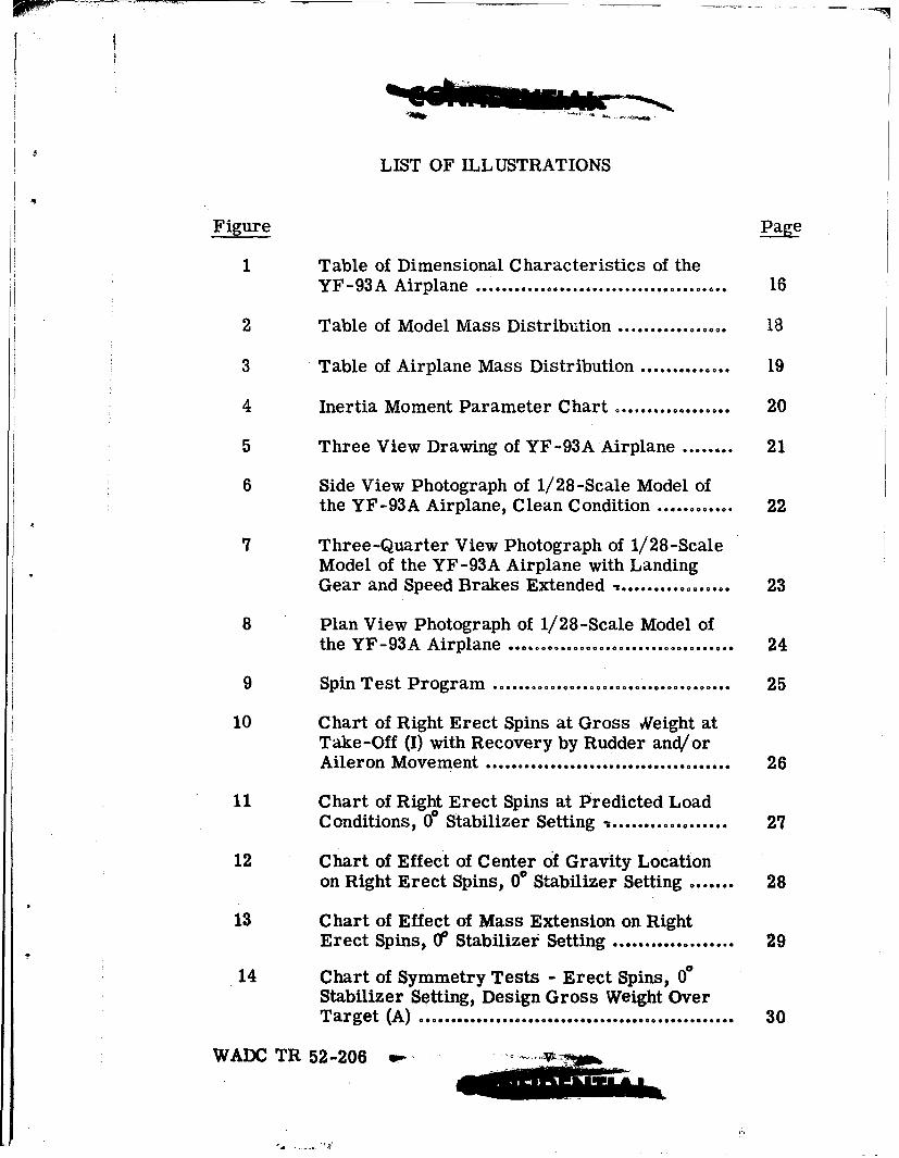
LIST OF ILLUSTRATIONS
Figure Page
1 Table of Dimensional Characteristics of the
YF-93A Airplane ....................................... 16
2 Table of Model Mass Distribution ................. 18
3 Table of Airplane Mass Distribution .............. 19
4 Inertia Moment Parameter Chart .................. 20
5 Three View Drawing of YF-93A Airplane ........ 21
6 Side View Photograph of 1/28-Scale Model ofthe YF-93A Airplane, Clean Condition ............ 22
7 Three-Quarter View Photograph of 1/28-ScaleModel of the YF-93A Airplane with LandingGear and Speed Brakes Extended - .......... 23
8 Plan View Photograph of 1/28-Scale Model ofthe YF-93A Airplane ...... ......... ....... ......o...... 24
9 Spin Test Program ......................... ............. 25
10 Chart of Right Erect Spins at Gross Weight atTake-Off (I) with Recovery by Rudder and/orAileron Movement ...................................... 26
11 Chart of Right Erect Spins at Predicted LoadConditions, 0i Stabilizer Setting ............ 27
12 Chart of Effect of Center of Gravity Locationon Right Erect Spins, 0 Stabilizer Setting ....... 28
13 Chart of Effect of Mass Extension on RightErect Spins, 0 Stabilizer Setting ................... 29
14 Chart of Symmetry Tests - Erect Spins, 00Stabilizer Setting, Design Gross Weight OverTarget (A) ................................... R......... 30
WADC TR 52-206 ,... .,.....•
LIST OF ILLUSTRATIONS (Continued)
Figure Page
15 Chart of Right Erect Spins Showing Effects ofExtended Wing Flaps and of Extended LandingGear, 00 Stabilizer Setting .......................... 31
16 Chart of Right Erect Spins at Predicted LoadConditions, +3 Stabilizer Setting .................. 32
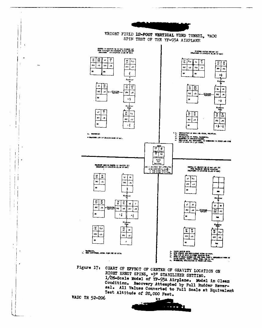
17 Chart of Effect of Center of Gravity Location onRight Erect Spins, +30 Stabilizer Setting ......... 33
18 Chart of Right Erect Spins, Model Clean VersusBoth Wing Slats Extended ............................. 34
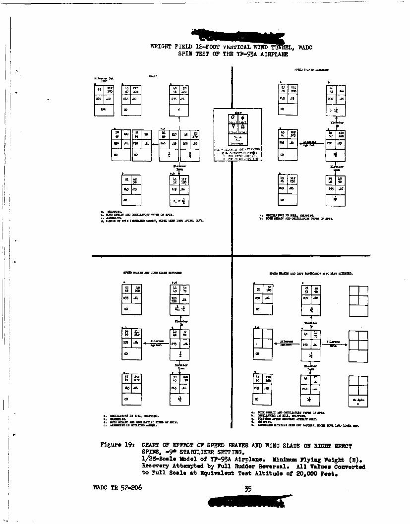
19 Chart of Effect of Speed Brake and Wing Slatson Right Erect Spins, -90 Stabilizer Setting atMinimum Flying Weight (B) .... ............. 35
20 Chart of Effect of Wing Slats on Right ErectSpins, -90 Stabilizer Setting, at Minimum FlyingW eight (B) ................ ; ................................ 36
21 Chart of Right Erect Spins with Speed Brakesand/or Wing Slats Extended, -90 StabilizerSetting at Design Gross WNeight Over Target (A). 37
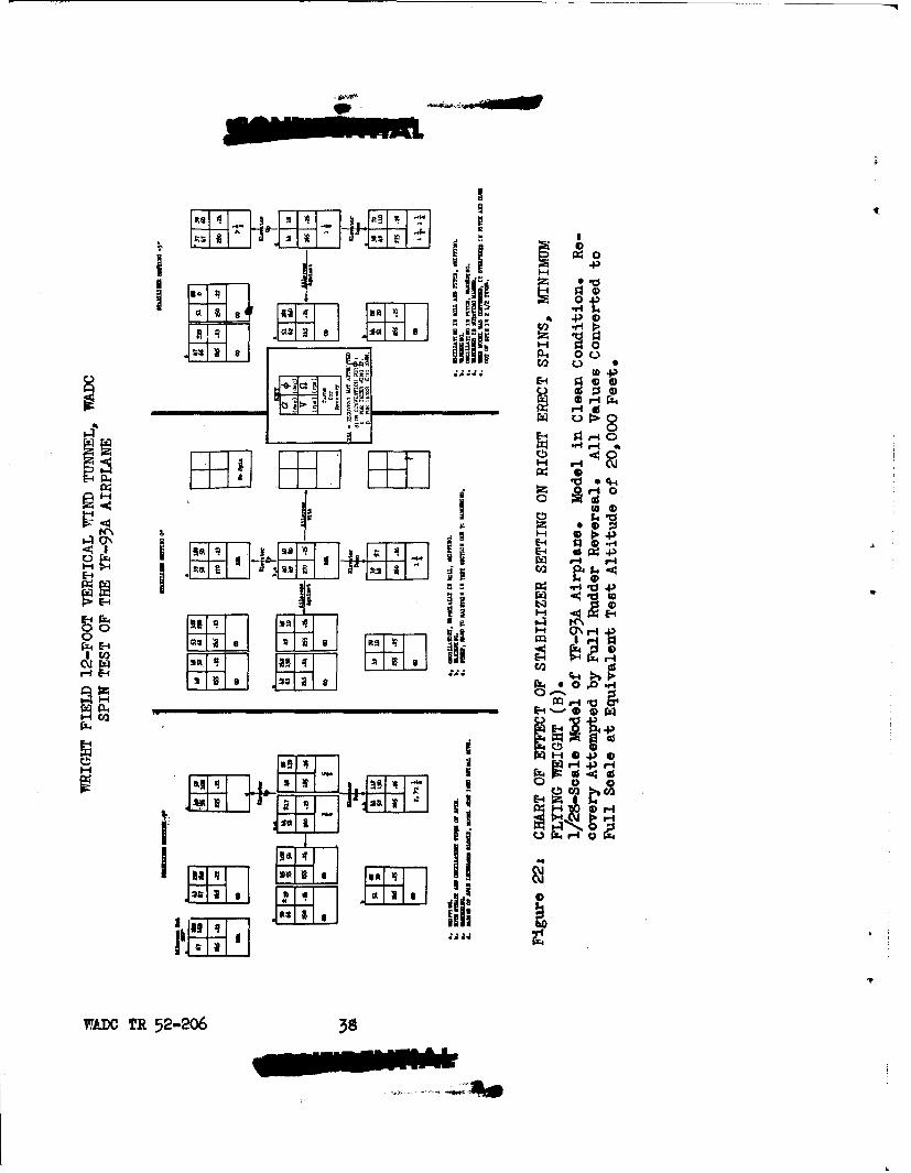
22 Chart of Effect of Stabilizer Setting on RightErect Spins ....................... ...................... 38
WADC TR 52-206 vi
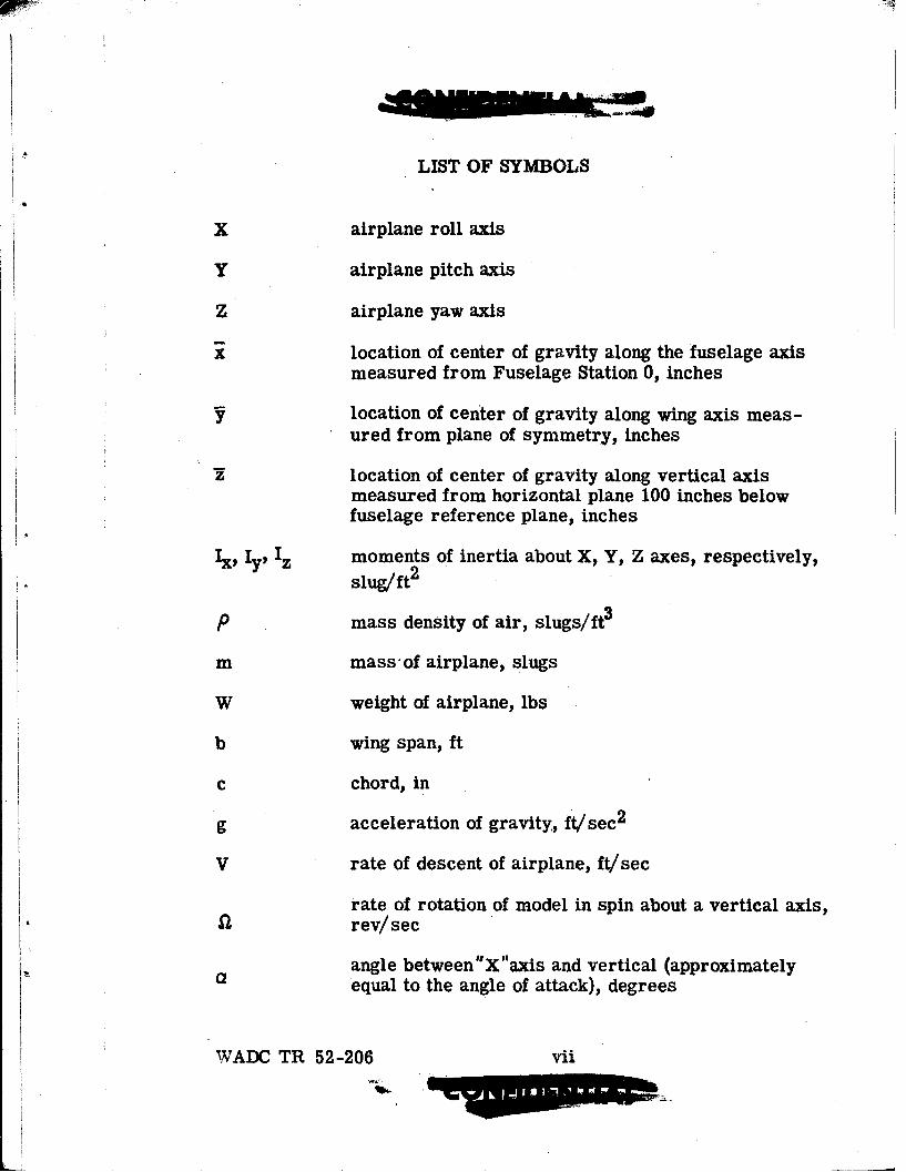
LIST OF SYMBOLS
X airplane roll axis
Y airplane pitch axis
Z airplane yaw axis
x location of center of gravity along the fuselage axismeasured from Fuselage Station 0, inches
y location of center of gravity along wing axis meas-ured from plane of symmetry, inches
location of center of gravity along vertical axismeasured from horizontal plane 100 inches belowfuselage reference plane, inches
I, Iy, Iz moments of inertia about X, Y, Z axes, respectively,
slug/ft2
P mass density of air, slugs/ft3
m mass-of airplane, slugs
W weight of airplane, lbs
b wing span, ft
c chord, in
g acceleration of gravity., ft/sec2
V rate of descent of airplane, ft/sec
rate of rotation of model in spin about a vertical axis,rev/sec
a angle between 'X "axis and vertical (approximatelyequal to the angle of attack), degrees
WADC TR 52-206 vii
Mow

LIST OF SYMBOLS (Continued)
angle between "Y axis and horizontal (U means innerwing up; D means inner wing down), degrees
Ix- Iy inertia yawing moment parameter
mb2
yI - Iz inertia rolling moment parameterib 2
I- Ixinertia pitching moment parametermb
WADC TR 52-206 viii

INTRODUCTION
The purpose of this report is to describe, discuss, and drawconclusions from an investigation of the spin and spin recoverycharacteristics of a scale model of the YF-93A airplane in the 'WrightField 12-Foot Vertical Wind Tunnel.
WADC TR 52-206 ix
SECTION I
GENERAL CONSIDERATIONS
The YF-93A airplane is a single jet engine, single-placefighter. It was desired that information be obtained, by model tests,concerning the spin and spin recovery characteristics of the air-plane.
For the investigation, a 1/28-scale model of the airplane wasconstructed of laminated pine by the contractor,. North AmericanAviation, Incorporated. Wing slats, wing flaps, speed brakes, andlanding gear were incorporated in the model design. Three empen-nage assemblies were provided to make possible tests at three dif-ferent horizontal stabilizer settings. It was then necessary to bringthe weight, center of gravity location, and moments of inertia of themodel to the proper scale values, a condition referred to as dynamicbalance. This was accomplished by installing lead weights at theproper locations to fulfill the imposed conditions.
The full-scale airplane undergoes important changes ofweight, center of gravity location, and moments of inertia as the ex-pendable load is changed or consumed. Tactical use of the airplanefrequently demands that the loads as planned during the design stagebe altered. Also, the possibility exists that the airplane has a massdistribution such that small changes will produce important changesin the spin behavior. The inherent limitations of accuracy in a modeltest make it possible that this marginal nature, if it exists, may notbe revealed by the model tests if they are limited to a narrow rangeof load conditions. Consequently, it is desirable to test the spinmodel over a range of load conditions which is more extensive thanthat for the full scale airplane.
The model of the YF-93A airplane was arranged to simulatenine load conditions. Four of these were load conditions given bythe contractor for the full-scale airplane. Five were extended orexaggerated load conditions selected by the project engineer. Afterpreliminary survey testing, the remainder of the test program wasconcentrated on those load conditions which had been found to becritical. All load conditions simulated a full scale altitude of
WADC TR 52-206 1

20,000 feet ( e 0.001267 slugs/ft3 ). Due to tolerances in the bal-ancing methods and atmospheric changes, this altitude varied for thedifferent tests between 19,300 feet and 21,000 feet. The load condi-tions tested were:
Load Condition Description
A Design Gross Weight over Target
B Minimum Flying Weight
C Design Rearmost Center of Gravity
D Center of gravity moved 5% ofMAC aft from design rearmostlocation
E Center of gravity moved 10% ofMAC aft from design rearmostlocation
F Mass extended along the fuselage(that is, I F = 1.15 INB)
G Mass extended along the wing(that is, IXG = IXB + 0.12 IZB
H Center of gravity moved 7% ofMAC forward from location forWeight Condition B
I Gross Weight at Take-Off
Measurements of the mass characteristics of the model arebelieved accurate to the following limits:
Weight, per cent +0.1
Center of gravity location, inches ±0.01
WADC TR 52-206 2NM I.

Center of gravity location, per cent of MAC ±0.3
Moments of inertia, per cent ±2.
The deviations of model values of weight, center of gravity location,and moments of inertia for all -load conditions are given in Figure 2.The maximum deviations found for the nine load conditions are:
Weight, per cent -2.3
Center of gravity location, per cent of MAC +3.8
Moments of inertia, per cent +3.5
Inertia moment parameter values for the full-scale airplaneand corresponding model values converted to full scale are presentedin Figures 2, 3, and 4. These may be used with Reference 2 in pre-dicting the recovery characteristics of the airplane.
A magnetically-triggered remote control mechanism was in-stalled in the model to permit movement of the rudder and/or aileronsor to release the anti-spin parachute. The control deflections usedare the maximum full-scale values given in Figure 1, unless otherwisenoted.
Model anti-spin parachutes of the flat, circular type weremade of nylon cloth. Drag tests were conducted with the model para-chutes to determine their drag coefficients. Values of drag coeffi-cient for the model parachutes varied between 0.81 and 0.83, basedon total flat area. An ejection tube was installed in the fuselage ofthe model to deploy the model parachutes in tests of recovery by anti-spin parachute.
SECTION 11
TEST EQUIPMENT AND PROCEDURE
The Wright Field 12-Foot Vertical Wind Tunnel is an atmos-pheric pressure, annular return, closed circuit wind tunnel with anopen throat twelve feet in diameter. The air flow in the test section
WADC TR 52-206 3

is directed vertically upward at a velocity that is controlled by thetunnel operator. The test section is enclosed by cord nets to pre-vent the model from striking solid objects during its spin and re-covery.
With the model controls set at the desired positions for a spintest, the model was launched by hand with a pro-spin rotation into theair stream. The test section velocity was adjusted by the tunnel oper-ator to equal the rate of descent of the spinning model, thus holding themodel in a free spin at the level of the test section reference lines.The spin was observed and recorded.
Recording was accomplished by means of special motionpicture cameras arranged to superimpose a time indication and anair speed indication on each frame of the film. All tests were record-ed by one camera photographing horizontally across the test section.For some tests, additional records were obtained by a similar cameraphotographing vertically downward along the test section axis. Allphotographs were taken at a rate of 64 frames per second.
The rate of descent, rate of rotation, number of turns for re-covery from the spin, and the angles of pitch and wing tilt were ob-tained by analysis of the films.
Recovery from the spin was attempted by abrupt movementof rudder alone, or of ailerons alone, or of rudder and aileronssimultaneously. Recovery was also attempted by deployment of ananti-spin parachute in certain tests performed to find the minimumrequired size of anti-spin parachute.
The test program was organized in the following way(Figure 9). With the 00 stabilizer and the model in the clean condition,symmetry tests were run in Load Condition A comparing right andleft spins (Phase I). No essential difference due to possible asymme-try of the model was observed. All further tests were made for rightspins. Comparative tests of all load conditions were then performed(Phase H) for the clean model and 00 stabilizer. Tests were also runfor the influence of landing gear extended using Load Condition A andthe 0e stabilizer. Tests of the influence of wing flaps extended forLoad Condition B and 0' stabilizer were run.
WADC TR 52-206 4

o . M
Tests were performed next (Phase II) for the influence ofall other changes in aerodynamic shape (i.e., wing slats and/or divebraises extended) for Load Condition B and the -9* stabilizer setting.A limited number of tests were also performed for this stabilizersetting in Load Conditions A and C.
Then tests were performed (Phase IV) comparing selectedload conditions for the clean model and the +3f stabilizer setting.Tests were made of the effect of wing slats extended in Load Condi-tion A for this stabilizer setting.
Limited tests of inverted spins were also conducted chieflyfor +3 stabilizer settings (Phase V).
Based on the above tests, the worst conditions for recoverywere selected and used for the anti-spin parachute recovery testsfrom which the minimum parachute sizes for both tail and wing-tipinstallations were determined (Phase VI).
Final recovery tests were made using the worst of the aboveconditions, and attempting recovery by aileron movement alone andby simultaneous movement of rudder and ailerons (Phase VII).
SECTION III
RESULTS
A. General
The results of the spin tests are presented in Figures 10through 22. The spin data presented were obtained from the testsand have been converted to corresponding full-scale values for theairplane at an altitude of 20,000 feet assuming that the spin geome-try remains the same. The model values which were taken are be-lieved accurate to the true model values within the following limits:
a degrees ± 2
f degrees ± 2
V per cent ±3
£! per cent ±3
Turns for recovery - 1/4
WADC TR 52-206 5
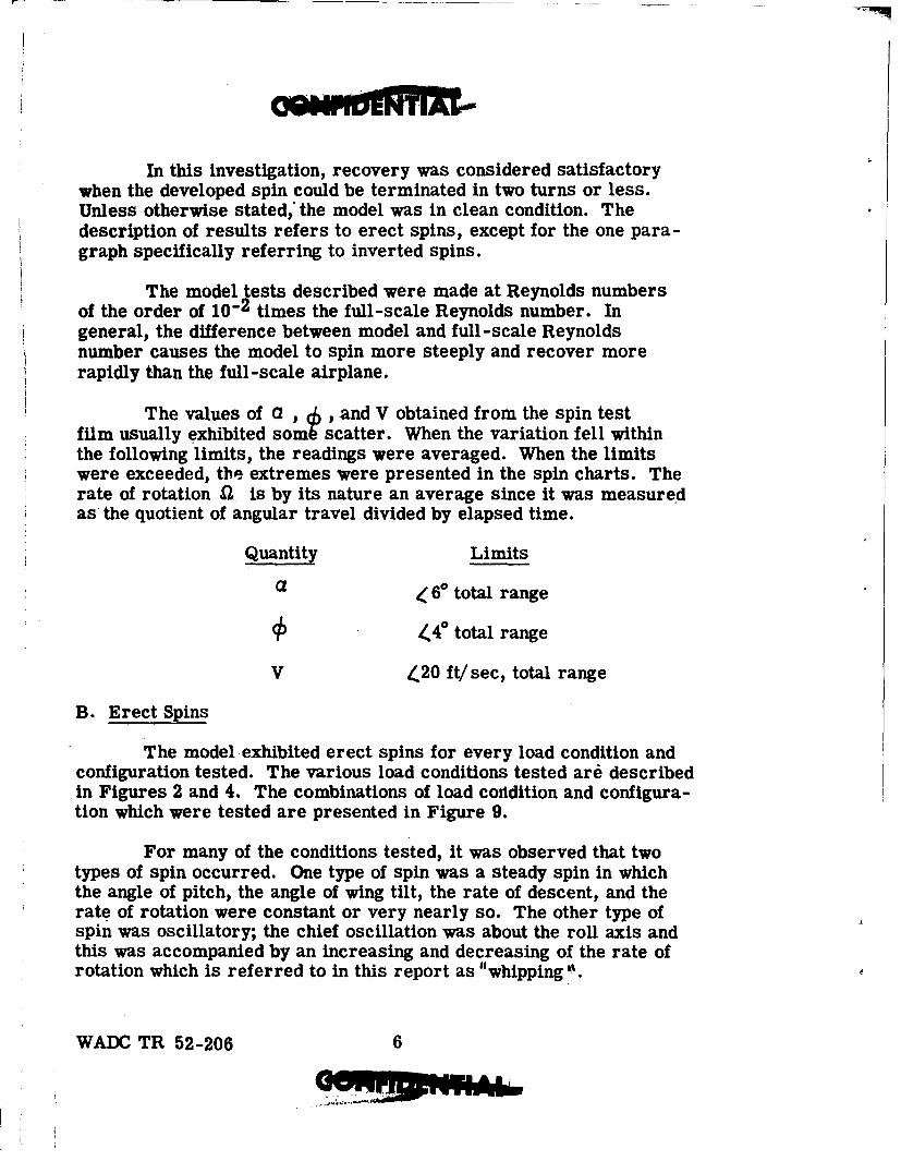
In this investigation, recovery was considered satisfactorywhen the developed spin could be terminated in two turns or less.Unless otherwise stated, the model was in clean condition. Thedescription of results refers to erect spins, except for the one para-graph specifically referring to inverted spins.
The model tests described were made at Reynolds numbersof the order of 10-2 times the full-scale Reynolds number. Ingeneral, the difference between model and full-scale Reynoldsnumber causes the model to spin more steeply and recover morerapidly than the full-scale airplane.
The values of CZ , ,and V obtained from the spin testfilm usually exhibited some scatter. When the variation fell withinthe following limits, the readings were averaged. When the limitswere exceeded, the extremes were presented in the spin charts. Therate of rotation Q is by its nature an average since it was measuredas the quotient of angular travel divided by elapsed time.
Quantity Limits
a 60 total range
0 /,40 total range
V 420 ft/sec, total range
B. Erect Spins
The model exhibited erect spins for every load condition andconfiguration tested. The various load conditions tested ard describedin Figures 2 and 4. The combinations of load coridition and configura-tion which were tested are presented in Figure 9.
For many of the conditions tested, it was observed that twotypes of spin occurred. One type of spin was a steady spin in whichthe angle of pitch, the angle of wing tilt, the rate of descent, and therate of rotation were constant or very nearly so. The other type ofspin was oscillatory; the chief oscillation was about the roll axis andthis was accompanied by an increasing and decreasing of the rate ofrotation which is referred to in this report as "whipping .
WADC TR 52-206 6

Another type of spin was observed which was oscillatory;this usually was found alone. In this, the pitch attitude varied irregu-larly accompanied by •hanges in the rate of descent.
In some of the spins, the vertical axis about which the modelspun did not remain stationary, but translated about the test section.This behavior is referred to as "wandering". At times, the spin axistranslated along a curved path which described a number of smallloops. This behavior is referred to as "nutating t.
C. Effect of Aileron Position
The effect of aileron setting was of major importance. Forall combinations of load condition and configuration when the aileronswere held "against* the spin (i.e., stick left for a spin to the right),the model would not recover by full rudder reversal and continued tospin, apparently for an unlimited period. When the ailerons were heldneutral, the model exhibited recoveries which varied from satisfactoryto unsatisfactory. These are discussed in detail below. When the aile-rons were held "with" the spin (i.e., stick right for a spin to the right),the model generally would not spin; instead, the launched spin wasusually terminated in a very few turns without control manipulation.The response of the model to aileron position was in agreement withthe NACA studies relating to inertia moment parameters (Reference 2).
D. Recovery by Aileron Manipulation
The pronounced effects of aileron position on the spin andrecovery characteristics led to tests in which the rudder was heldstationary and recovery was attempted by reversing the ailerons fromfull 'against" to full "withi the spin. The test results are presentedas part of Figure 10. The model spun with the rudder set full with,neutral, or full against the spin. Recoveries were more rapid whenthe rudder was set against the spin, and slower when the rudder wasset with the spin. With one exception, the recoveries for these testsoccurred in two turns or less.
E. Recovery by Rudder and Aileron Movement
Tests were made for the load condition considered most ad-verse to recovery (Take-Off Gross Weight or I) with the model clean,and also with speed brakes extended, attempting recovery by full
WADC TR 52-206 7

rudder reversal from with to against the spin and aileron movementto full "with" the spin. These results are presented in Figure 10. Itcan be seen that the recoveries by simultaneous manipulation ofrudder and aileron are faster than recoveries by rudder alone, or byailerons alone. All recoveries by simultaneous manipulation ofrudder and ailerons occurred in two turns or less with one exception(2 1/2 turns). Most of these recoveries terminated in vertical rollingdives at high speed.
In general, it may be stated that the ailerons are more effec-tive than the rudder in maintaining the spin and in terminating thespin for the model of the YF-93A airplane.
F. Effect of Elevator Position
The effect of elevator position on turns for recovery was notconsistent for all the combinations of load condition and configurationtested. It appears that elevator down more often led to slow recoveriesand that elevator up more often gave rapid recoveries. Numerous ex-ceptions can be found.
G. Effect of Stabilizer Setting
The tests run at different stabilizer settings (-9V, 00, and +3r),with all other conditions the same, did not reveal any consistent orpredominant trend regarding the turns for recovery. It was ob-served that down stabilizer (-9P) gave somewhat flatter spins (pitchattitude). Some data from these tests are presented in Figure 22.
H. Model Behavior for Predicted Load Conditions
As stated in Section I of this report, four of the load condi-tions specified by the contractor were simulated in the test programalong with other (exaggerated) load conditions. The following infor-mation was obtained from these tests at predicted load conditions.Data are presented in Figures 11 and 16.
1. Design Gross Weight Over Target (A)
Tests of the clean model at this load condition generallyshowed steady spins; for many of the conditions both steady andoscillatory spins were observed. With ailerons neutral, the re-coveries attempted by full rudder reversal were frequently
WADC TR 52-206 8

unsatisfactory (greater than 2 turns). As stated above, when the aile-rons were set "against" the spin, rudder reversal never caused re-covery. The initial symmetry tests of the model were made at thisload condition (Figure 14).
Where steady spins were obtained both to the right and to theleft, the data show very close agreement. Since these tests were per-formed only to verify the model symmetry, no attempt was made toextend the tests of left spins to see whether the two types of spinswere found to correspond to those for the right spins.
2. Minimum Flying Weight (B)
Tests of the clean model at this load condition more oftenexhibited oscillatory spins than Load Condition A. Recoveries forneutral ailerons were generally faster and were satisfactory. Rudderreversal never caused recovery when the ailerons were "against thespin. For this load condition, the rate of descent and the rate ofrotation were generally lower than for the Load Condition A.
3. Design Rearmost Center of Gravity (C)
This load condition differs little from the preceding one,the main difference being a rearward center of gravity shift of about1% of the mean aerodynamic chord. Only brief tests were made.The data indicate slower recoveries for this load condition than forLoad Condition B. This is more likely to have been caused by coin-cidence and scatter than by essential change in the spin.
The data are interpreted to mean that this small centerof gravity shift, with corresponding changes of the other mass distri-bution quantities, did not produce a discernible change in the spinbehavior.
It should be pointed out that the photographic determi-nation of the attitude of the model during the spin permits values tobe obtained only twice for each revolution of the model (where themodel is correctly, or most nearly, oriented with respect to the filmplane). There is no assurance that the values obtained during an
* oscillatory spin are the extremes of oscillation, unless very long* spin records are obtained.
The values obtained for the rate of rotation and the rate
WADC TR 52-206 9

of descent are average values. It appears that the rearward centerof gravity shift (from B-to C) did cause a small decrease in the rateof rotation; and this is in agreement with the general effect foundwith rearward center of gravity travel. But the numerous excep-tions and the small magnitude of the differences found make it im-possible to say that the 1% center of gravity shift was responsiblefor a decrease in rate of rotation.
4. Gross Weight at Take-Off (I)
This load condition represents the aircraft with additionalweight close to the center of gravity as compared with Load Condi-tion A.
It can be seen from the data that the model spun at ahigher rate of rotation and a higher rate of descent for Load Condi-tion I than for Load Condition A. The attitude was about the same.
As before, when the ailerons were set "against" the spin,full rudder reversal never produced recovery. With the aileronsset neutral, full rudder reversal produced satisfactory recoveryonly when the elevator was up.
From the data, it appears that recoveries (aileronsneutral) for Load Condition I were much slower than for Load Condi-tion A. The two slow recoveries for Load Condition I seen in Figure
S11 are questionable. The signal flag, indicating rudder movement,malfunctioned on both of these tests; and the film quality was not goodenough to permit a positive identification of time of rudder movement.
* The values given for these two tests were specified after long studyof the film, but they may be in error. Later tests, presented inFigure 10 were made with external aileron rigging installed. Theyexhibited much faster recoveries for Load Condition I.
The data of the model behavior for predicted load con-ditions indicate in general that Load Conditions A and I are moreadverse to recovery than Load Condition B or C. The model neverrecovered by full rudder reversal ailerons were set "against" thespin. Recoveries by full rudder reversal with ailerons neutralvaried from unsatisfactory to satisfactory. Elevator up led tofaster recoveries than elevator neutral or down.
WADC TR 52-206 10

I. Effect of Center of Gravity Location
Tests were performed at extreme forward and aft center ofgravity locations beyond the limits predicted by the contractor. Dataare presented in Figures 12 and 17.
1. Center of Gravity Moved Aft
As the center of gravity was moved aft from the RearmostDesign Location in two increments of about 5% of mean aerodynamicchord each, the radius of the spin increased greatly. The rate of rota-tion 11 decreased greatly. The model exhibited less stable spins. Re-coveries by rudder reversal were satisfactory for ailerons neutral;the model did not recover by rudder reversal when the ailerons werepositioned "against" the spin.
2. Center of Gravity Moved Forward
When the center of gravity was moved forward 7% ofmean aerodynamic chord from the location corresponding to MinimumFlying Weight (B), the rate of rotation 11 increased. The recoveriesseem to have become slower although data are scanty. Recoveries byrudder reversal were satisfactory when the ailerons were neutral.The model never recovered by rudder reversal when the ailerons werepositioned "against "the spin.
1. Effects of Extending the Mass Along the Fuselage or Along the Wing
The data'for the two mass extended conditions are presentedin Figure 130 The condition for Mass Extended Along the Wing (G)was selected to obtain an inertia moment parameter change for thisload condition about equal in magnitude to the extreme mass exten-sion along the fuselage. This may be seen in Figure 4.
The model did not exhibit any important differences in spinbehavior with the mass extended in either direction from the basicLoad Condition B. For both mass extended conditions, the rate ofdescent increased slightly, probably due to the greater model weight.It appears that the rate of rotation decreased for both extended condi-tions, but the changes are small. Load Condition F led to one Slowrecovery. In general, recoveries were about the same as for tle pre-dicted load conditions, including the non-recovery by rudder rc versalwhen ailerons were held against the spin.
WADC TR 52-206 11
K. Effects of Speed Brakes
Data from tests with model speed brakes extended are givenin Figures 10, 19, and 21. With the speed brakes extended, recoverieswere slower and more oscillatory spins were encountered. The gen-eral recovery characteristics were the same'as before (i.e., no re-covery for ailerons "against"the spin).
L. Effects of Wing Slats
Tests were performed with both wing slats extended, rightslat extended, left slat extended, and both slats and speed brakesextended. The data are presented in Figures 18, 19, 20, and 21.
On the whole, recoveries were somewhat faster with bothwing slats extended than with the model clean. Generally, the rateof rotation was lower and the rate of descent higher with both wingslats extended. The effect of aileron position on recovery was thesame as for the clean model.
With the left slat extended and the model launched in a rightspin, the behavior was about the same as for both slats extended.The radius of the spin was somewhat greater and the spin lessstable.
With the right slat extended and the model launched in aright spin, the spins were somewhat steeper than for the left slatextended. Large radius spins were again encountered as well asmarginal spins.
Recoveries for either of the unsymmetrical slat configurationsappeared somewhat better than for both slats extended. The generallyunsatisfactory recovery by rudder reversal (when ailerons were posi-tioned "4against" the spin) were encountered for all slat configurations.
M. Effects of Landing Gear
Data from tests with landing gear extended are presented inFigure 15. No important differences were found between the landinggear extended configuration and the clean model. Recoveries wereunsatisfactory throughout, except for ailerons and elevator neutral.
WADC TR 52-206 12

N. Effects of Wing Flaps
Tests were performed with wing flaps fully extended. Dataare presented in Figure 15. The spins were somewhat less stablewith wing flaps extended than with the model clean. No other generaleffect was noted. The recovery behavior was essentially the same asbefore.
0. Inverted Spins
Brief tests of inverted spins were performed. Results arepresented as part of Figure 16. The inverted spins were not verystable. Satisfactory recoveries were obtained for those controlpositions for which the model spun.
P. Parachute Recovery Tests
Tests were performed of recovery by anti-spin parachutesfor a number of the more adverse load conditions and configurations,holding all controls in the most pro-spin positions (rudder full withthe spin, elevators full down, and ailerons full "against" the spin).Both wing-tip and tail parachute attachments were tested. It wasfound that a flat circular parachute of drag area CDS = 28 ft 2 (full-scale) with a 5.5 foot towline would be needed for a wing-ti chute.For a tail parachute the recommended drag area was 86 ftz (full-scale) with a 28 foot towline.
SECTION IV
CONCLUSIONS
Based on results of spin tests of a 1/28-scale model of theYF-93A airplane, the following conclusions regarding the spin andrecovery characteristics of the airplane at an altitude of 20,000 feetare presented:
1. For all load conditions and configurations tested, withailerons held "against"' the spin (i.e. stick left for a right spin), re-covery attempts by full rudder reversal will fail to terminate thespin. With ailerons neutral, recoveries will vary from satisfactory
WADC TR 52-206 13

to unsatisfactory, depending on load condition and configuration.
2. For all load conditions and configurations tested, satis-factory to marginal recoveries will result from full rudder reversaland simultaneous movement of ailerons to full "with" the spin (i.e.stick right for a right spin). The airplane will generally go into avertical rolling dive. R is believed that the airplane can be recoveredfrom this vertical rolling dive by normal control manipulation.
3. The elevators should be full up during the first part of thespin recovery attempt for fastest recoveries.
4. The Gross Weight at Take-Off and the Design Gross WeightOver Target conditions are more adverse to recovery than any of theother conditions tested.
5. Speed brakes extended will have an adverse effect on rercoveries. If a spin is inadvertently entered with speed brakes ex-tended, they should be retracted and recovery be made as outlinedabove. Wing slats extended will have small, beneficial and rather in-consistent effects on recovery. Landing gear and wing flaps will havesmall and inconsistent effects on recovery.
6. Satisfactory recovery from inverted spins is expected byrudder reversal.
7. A parachute of drag area CDS = 28 ft2 attached to the outerwing tip of the airplane with a towline 5.5 feet in length should giveemergency recoveries from any spin encountered. A parachute ofdrag area 86 ft2 attached to the rear end of the fuselage by a towline28 feet in length should also be satisfactory.
8. The YF-93A airplane will not meet the requirementof Army Air Force Specification Number 1816, dated 15 Iuly 1945,Paragraphs D-2a(2)(c) and D-2a(4), which requires that fighter air-planes recover satisfactorily from spins by full rudder reversal,holding ailerons "against" the spin.
WADC TR 52-206 14

SECTION V
REFERENCES
1. Knackstedt, W. F. The Problems of Spin Investigations in aVertical Wind Tunnel. Office Instruction, Wind Tunnel Branch,Engineering Division, Air Materiel Command, 1948.(Unclassified, English).
2. Neihouse, A. I. A Mass Distribution Criterion for Predictingthe Effect of Control Manipulation on the Recovery from a Spin.Advanced Restricted Report, NACA, August 1942.(Unclassified; English).
WADC TR 52-206 15
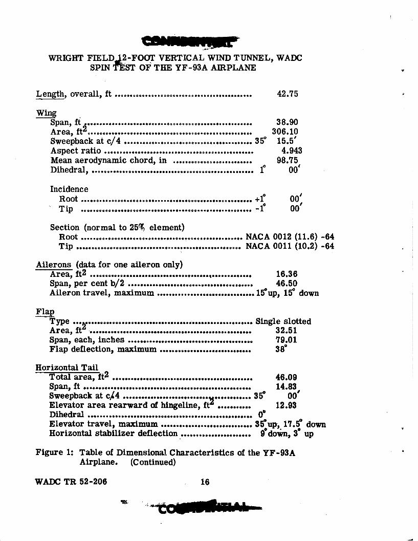
WRIGHT FIELD.2-FOOT VERTICAL WIND TUNNEL, WADCSPIN ¶fST OF1 THE YF-93A AIRPLANE
Length, overall, ft ............................................. 42.75
WingSpan, ft . 38.90Area, f2 361
Sweepback at c/4 .. 35°............5o.............°.......... 35Aspect ratio ..... .... o.................. o ......... ... 0 . ......00 4.943
Mean aerodynamic chord, in ....... °.....°. .0...... 98.75Dihedral, ..... ...... .... g..° .. ..................... 1° 00'
IncidenceRoot .......... ..... ..... ........ ................... . +10 00Tip .o ....... oo ........ o........°.......... o............ o...... .1° 00•
Section (normal to 25% element)Root .............................. o ..................... NACA 0012 (11.6) -64Tip ...... og.....g... .......... o .... o ............. o ... NACA 0011 (10.2) -64
Ailerons (data for one aileron only)Area, ft 2 .. .o ... .g.... .... ......... g.. ......... 16.36Span, per cent b/2 ......................................... 46.50Aileron travel, maximum ................................ 15up, 15 down
FlapType ... ....... o........................................... Single slottedArea, t". °..........,...............32.51
Span, each, inches ........................................ 79.01Flap deflection, maximum ..... ......... g................ 38W
Horizontal TailTotal area, ft2 .... ....................................... 46.09Span, ft o........... .. g...... .... .....° ...... . .. g.......... 14.83Sweepback at c$4 ...... ,...... .... o............... 350 00Elevator area rearward of hingeline, ft2 ........... 12.93Dihedral ....... .. . ................... e..e..... ........... 0Elevator travel, maximum ................... .. 35"up, 17.5 downHorizontal stabilizer deflection ....................... 9°down, 3° up
Figure 1: Table of Dimensional Characteristics of the YF-93A
Airplane. (Continued)
WADC TR 52-206 16
a UU
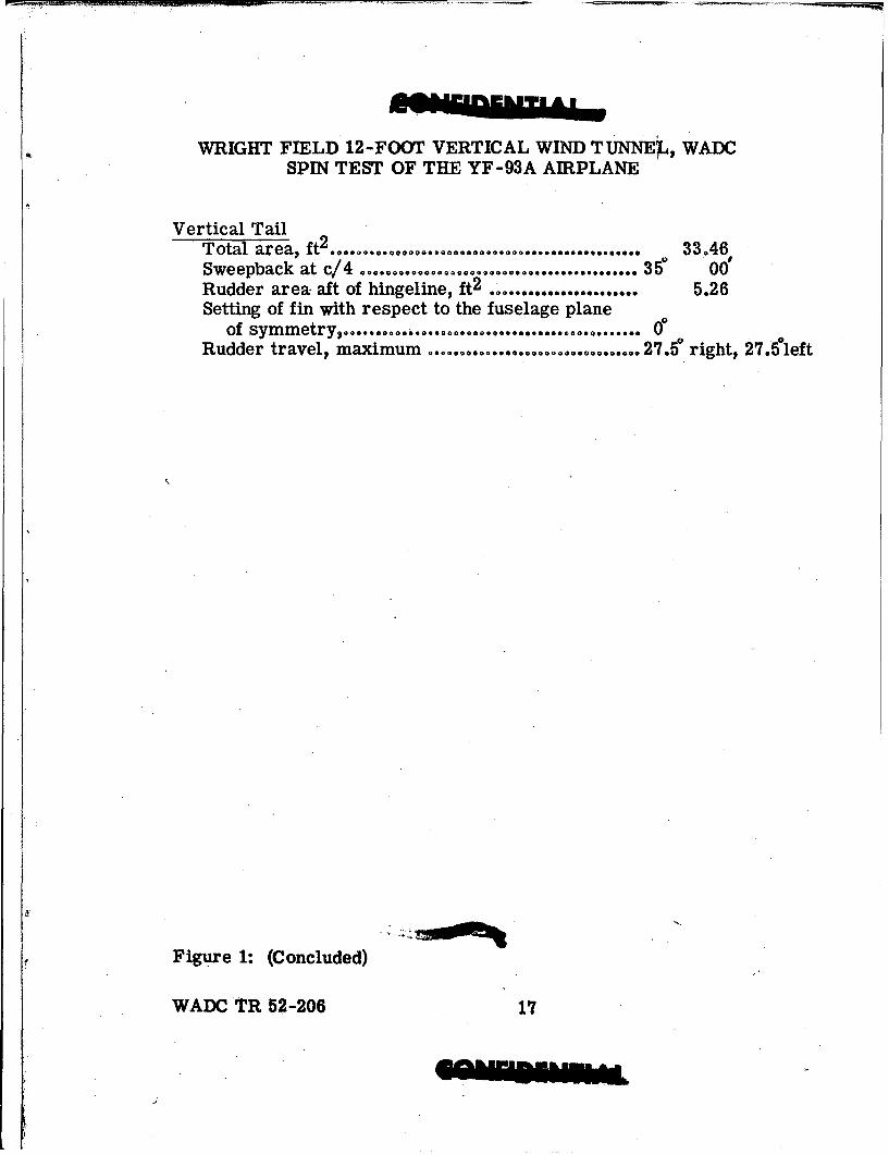
WRIGHT FIELD 12-FO(YO VERTICAL WIND TUNNEL, WADCSPIN TEST OF THE YF-93A AIRPLANE
Vertical TailTotal area, ft2 ................................................ 33.46Sweepback at c/4 ............ ........... ................... 35° 001Rudder area aft of hingeline, ft2 ...................... 5.26Setting of fin with respect to the fuselage planeof symmetry, ..... .. ,................°..... 0°
Rudder travel, maximum ............................. right, 27.Sleft
Figure 1: (Concluded)
WADC TR 52-206 17

CONFIDENTIALW aM. FWD. 12-y=OT VEMIC&L VIM) T , SMJC
SPIN TST OF THE rF-93A AIRPAL
CONMTION 1ECRIaTION W Ix IY Iz 2' 7 I XIO 10 xI
Deelp _ _ _ _ _ _ _ _ __s v_ _ _ _ over - nr
A T araf -. .210 M O 30 .27. 96. 9347 P73 2B(Deviations per oent) -0.7 1.9 0.1 -07 0.2g 0.~ - __
Mxami Fying iht 19 9250 3970• 46300 230.3 89.6 1-%07 -09 496-0.3 1.5 1il 0.2 0 0.2
C Htearwat. Center of Gravity. 26100 9250 39500 LOX.0 231.14 89.5 :'400 L9
-1.1 1.03 0.o1 0 0.- 0....D Center of Gravitqy Movd
St IIAC aft from C. -64 -25 -3W -0W 23. 99.5liWQ...n..
0.7 - - - -0.4 0Center of Gravity •oved 95aO 9 &0 = 54900 22.1 99.9 49 ."96 _76l0X uzc.aftfrcanC_________aftfr _____ 3.2 - --- --- -0.9 -0.5 1
F Mw Extended Along Piuselai 17000 9500 P5400 521400 230.5 90.1 -:ia4W -88 537- - 0.6 - -0.2 -0.3
C MUM. 14aCtended Along lfling 1660 15000 4% 53100 234.1 89.14 ..ý6 ~490-- 2.4 - - -3.9 o.4
Center of GraW1yt# Mo0e987% LAC fwd. frnaD B 2 0 9350 _20 49_ 223.4 89._ _a9_- 5D3
6.0 - - - 0 0I Cwoes leight at 't Off 2590 11050 49900 1570 227.0 87.3 ipd -65 393
2.3 3.5 1-1.5 1-1.2 -0.3 1.8
Wiiht in iu n gf 2 renoe jlane. for Ca location,Moments of inertia in sl-ft2 2 iseur•d in in Incmhe normal to a vertical plane
specified about body axei through C. thrcough fuselage station 0 normal to. the FRL.Errors in CO location given in % NAC. I euAej in inoas mmal to a beelo ntalXangth of MAC Is 98.75 inches plans 100 irnhes below the FRL.
In Y direction, CO deviation was less than 0.1% MAC.FUM 21 19M MAW DISTRIBUTION TAEXR. 128-8aale model of lF-93A Airplane (all value converted to full scale).
IN= TR 56406

to4
*0Q 9-40
Is 0I
or-43 0432 -V4 94 PA
o A44 IN 0
4 11 __ a N
C4-
00
c W,
MWA TI 52m2O"1

WRIGHT FriEL 32-FOOT VýJMICAL EIND TUMIEL, WAISPDI TEST OF TIM YF-93A AIRPIANE
r4 *04
0 *e0 Values for Free-Spinning Model
Predicted FulI-Scale Values
SNOTEs 1. Iatters Refer to Load Condition
2. Prim Marks Indic~te Pret ýct,ýdFull-Scale Values
I lii xzz / -
Relatdve mis/ itiuinaci igicesd
7 T A IAX__ - 0
, z z III II,8 2 V / I / I1I•;9 A ~ Il l
•eal•mssdsrbtonaogwngicesd
FX••, A M•Z •A,• HA•• -•AA•NO•
If. .... :,'•II

C44
rZ$4
r294
3610 FT
WFADC TR 52-206 21
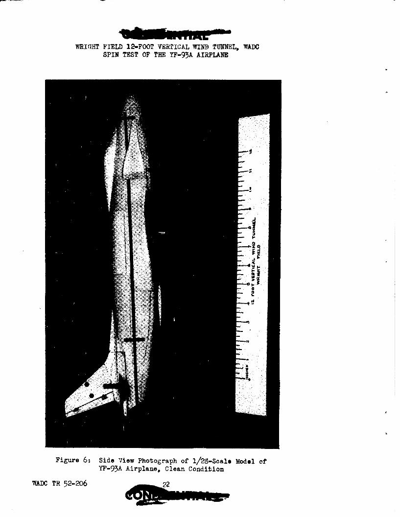
WRIGHT FIELD 12-FOOT VERTICAL WIND TUNNEL, WADCSPIN TEST OF THE YF-93A AIRPLANE
Figure 6: Side View Photograph of 1/29-Scale Model of
YF-93A Airplane. Clean Condition
WAXC TR 52-2o6 2

WRIGHT FIELD 12V-ERTi /IiTCAL 77IND TUNNEL, WADCSPIN TEST OF THE XY-93A AIRPLANE
Figure 7: Three-Quarter View Photograph of 1/2g-Scale Modelof YF-93A Airplane with Landing Gear and Speed
Brakes Extended
WADX TR 52-206 2
6~i

VW ar-T-FIE-LD 12V -MAIA ".£i'iL TUNhNEL, WIADCSPIN TEST OF THE YF-93A AIRPLANE
Figure 9: Plan View Photograph of 1/2$amSoale Model of YF-93A Airplane
WADC TR 52-206

9RIGHT FIELD 12-Ft)OT V!DRTTCAL -dIND TUNUMLI WADCSPIN TE&iT OF TIM YF-93A AIRPIANE
HH
T 0 _ X
CONK MULETI ON A 13 C .D .E F G .H I1
00 0 0 0 0 0 0 olI*CLEAN +.3@ 0~; +3"30 .
WING SLATS 1-3' -9 gEXTENDED 19
LEFT' SLAT0(OUT) 101,M))EXTINE11____
RDI{IT SiLAT9
,WiING FLAPS 00XTE MM D
ýiPLED BUI~ES .09 9
iý:TENDLD -_0__0__0
WING SLATS AND,SPEED 1BRAKLS -90 -90
-EXTENDED- --- -
IMVT (OUTrn1olii))SIATi,14D SPEED I3RAKES -190
EXTENDE D
LAN4DING ~ 0EXTENDED 0
OTHER a., b c
a.LEFT ERECT SPINS FOR CLEAN MODEL, QOc STABILIZER SE:TTING.b. LEVi' IN`,ERtBD SPI1LS IMR CLEAN 11OIEL, 00 STABILIZER SETTING.c. RICIIT INVERTED SPINS~ FOR CLEAN MIODEL, +3* STABILIZER SETING.
*RECOVERY ALSO AT"EMPTD BY SIiIULTATMOUS RUDDER AND AIlERON MOVDEKNT.3 RECOVERY ALSO ATMPUTED BY ALILERON YOV~.EM11 ALONE.
FIGJRE 9,. SPIN TEST PRd~r1AQ 1/29-.SCALE YOD)EL OF TIM, YF-93A AIRPLAN,'E.
iiA1X T-z 52-206 25

WRIGHT FIELD 12-FOOT VERTICAL WIND TUNNEL, WADCSPIN TEST OF THE YF-93A AIRPLANE
IO'Ja AT="PED BY SMULTAIR S MOVE0ENT OF M C09RY ATTMIFtED BY R0 1 REVERSAL AND BY SI0 N NO0 SRM= AIM A6LERD50 TO EX ANTI-.FIN POSITDION- WOTh10 OF R I 6A AOIRmjN TO E0T11EU ANr-,8FI POSITION
-STAABILIZEO 01TTI1O -0- um 8PED BM2A9KESS mmD) STABILIZ0 SETTINO 0' M1TN MOD2L IN CLEAN 2O9EIT2ID
50. lIO ~52 2.00
32300 .29 32330 2 335 .32
1_ m
8D ma 36 8V 111
a. ON NIUD AND OOOH.OATONI 00280 SPI)1 *. OCDILARTOR, UIPPINO (¶21AT IS,fl' Zi- AND 1 •oso iw •)
O. UNINNO IN 2116A1110 11A11. 0. 00TH STED! AND ONGOIMOE T259 OF SPIN.
5101INITIAL 9050100O1TO INITION 00R1102010N0GO01510 00 AO1 TO INFO OF 004031V 22 A RE 0 oio 5163. V9602I6
1ONHKh/ ATTdING 0D NIT MAULIN COERAL, 0510 105*122OFR AT2921*2 62112 00 0000*1A ANTI-YSPIN A011U .
•rm S• AT 1*12 9• AT 3 016 AT 06001.1220 IT•IN 0• N1IT SF290 102.126 102222620.0' NIrl . 2a7.50
F, •T1 FF F 7FO F•OiTi•Ta• 1W
AL30 165
50 612 0.0609 5 6 3 22 0 660 11r,5iii 310 .29 305.3 05 .730 .2Ag.1Co ANA,,
b~2~ 412~ LLU"1
":BORTH SP)TEAD ANDL OE.,SPIN IA.TO 0M T UYPES r 8TAIO. AT.
3OT GTA .3ITH. ATT.nA29OFND
C. P100206 OF 32908 02.1- T EA D SPIN TEA 10CIL1A LItNN1 MOOF SPIN
MN0INIT1o Ful0lNT SFICK FULL Pq IvS-eP Test V E O F F L An PoFT HUD= FeetL0 .00(AILERON)T FIL TISPN tR5 10. 00-O08 I A F S T U D N I A
WIHRECOVERY TEPBYALRNRVRA lVRAMM BY RUDDER REVERSAL AILERON MOVEIAENT.
WAD TR 52 20 3uP d U2Y! 1

WRIGHT FIELD 12-FOOT VERTICAL WIND T TUNNEL, WADCSPIN TEST OF THE YF-.93A AIRPLANE
a"I oarA tom-O05 (I mia wes =a20 OVER TAJ1T (A)
51 52O3 27 2
520 1 2 29D 2. 320 2 3720 26
52. 0 7. 0 4~4 44~44I17H4
30. 22 % 37. 2'0
11.20050 10 0 50 107 40 R0
4 1 5 DN 1 1 1 0
32 .337.0 .30 2 95 2 320 .30
o >t. 0I ODO 2 tbPPI0O.
b: 301 WHIPPING AND SLIMED STo • , WANDRING SPIN.
%N RUDDE •WD OR IF FIL Wj=m TRAVEL XLS OBTAINED. ,-1 mI&RCININ
SI •I c. POW, 00112F2R0
00130)~~fý 91l2 r51(0 02
0 T R I7000 ,1ING70 . U NT MUCIK C32 OF GRAIT (C)
1053 320 3 I18UFT 5 I
£1.,ooo
Up
Up24 17 11Dy2il7.5 Ale21 Aglr•llrr
r• All*AKid1
41
• OBIIATORY, E.SPECIALLI IN ROLL, WHIFFIN(4 11NEIG
b. SO , 0 TO AI0A0 IN 30? 2000000 00 000AN7162. 0. ALSO HAD A0I O=ULLATOO7 SPIN WITH 10107PIN0.STEW WMTO MINTIN TOTSMO DG To 'SEN06d. ALSO H•AD A'STEADY SPIN.a. ALSO 7AD STOP ST0AD0 0A13200 S2IN, IN .1RIGH R0202 IN=E 300.L
MOIM 20)70ED 0ur OF SPIN.f. MODEL lMaImTED ERRATIC OSCILLATINo MoOMENT A0 D FELL 0 OF SPIN.
Figure I1: CHART OF RIGHT ERECT SPIN AT PREDICTED LOAD CONDITIONS, 00STABILIZER SETTING.l/28-Scale Yodel of YF-93A Airplane. Model in CleanCondition. Recovery Attempted by Full Rudder Reversal* AllValues Converted to Full-Scale at Equivalent Test Altitudeof 20,000 Feet.
WADC TR 52-206 27

WRIGHT FIELD 12-FOOT VERTICAL WIND TUNMEL, WADCSPIN TEST OF THE YF-93A AIRPLJ\Uf.
cO=~e twos~ MM,, or nor le)A00 LMAt 25.9% OfMW
~U40 00 211O 174 UMO
a t 2 22 TO13021.
--7- •.--o- - • --
A0 .2 SOS .E3
26 .1 AO.0.t 270 .2604utUt
*. ~ ~ n" wUA0.A
-- tWft~MM WAIOAOIX . .ir nN 3• • €•l•••0 IsBI?• ~t0 1
8. lMN A EmlEA U i0OIXCO I•At•0L MA0W". C) E 000 OP MIX.
T. mW * k1 Dr • No2ZAs U y A e U.
FiXue 012 EART F FFCT OF CENTER OF GRAVIT LOCATION 6 ON ARIG(I
10EC SPNS 00 STAILZE SETG
pCondAition Recovery1 00 Atlte medb u mw Rude Revesal
Altitude of 200000 Fee0
go% .10
IIUTOr ApI. IOKIM: t
1uMM1 6. I DA MMlILMMPOI E SM 1 1 501 N MMM
* OWLi~ MAMUZ MMO. MrO ofX armm fE an oE.
l/2~-8ale Mdel o YF-9A Airpane Model= iM ClAnD
VT 52-206 AM
;Iid:OV= 7

to
.12 U 4:
E-4 Fu-4 0 0-)
0*4 1Pr4.,1.4 004
E-4-
92 E-4 FuS Fi8 I114?]r 'sp
46-4a 0 .~
~4)r
LL~JLLJLLLjdr-4 £o
:TTI]C; m~4UA
E-g!a~ j 00 i
son
M=fl TR 52-206 29

~ 0
N_______ o ~~
I IDE-i p 4 0
CO r".10CE-4 N 4C'.4D
C02 r 4 2
P4 ms
PC.) C3 'd ý
RI I t !2 - ot
WADC TR 52-206 30

WRIGHT FIELD 12-FOOT VERTICAL WIND TUNNEL, WADCSPIN TEST OF THE YF-93A AIRPLANE
NMUM FLYI2G WRIKET (B)
• . IN alnE CONITION ao HAn H
39 1 in
19o 01
00 I0R
*o 211 inoWEA
• OGGIUAWT•INKY .I6UM 12 MUL, MUF 0021 A 9MMlt ý=30ir SPIN AM A~l X.LdTIZ•Et
.* ONC mIUMOI IN AML AND PITON, VUM3 % 1123M ,.d. MAMB. IN N10lLN.I•
DENN GROW WEIGHT OVER TARGET (A)
N IN GmEA 00112104U010 MAN,? R--7
n37 .1 , .) 2DL..
2951 .2923201.2513203.3
- 700lONE.112 DDEIa. 13A t~r
320 .30 300 .30
2€1*' •FAdU=• 13o8/00W
271 7 SIR 512 t 0 W -5 3 4J*
40 7U. 27 Spal
GO5 226 22t .9 &,in CO3 a ,
ii ~ ~ ~ ~ . 0.. rill n mi... EBIUL
Figure 15s CHART OF RIGHT ERECT SPINS SHOWING EFFECT OF EXTENDED WING FLAPSAND OF EXTENDED LANDING GEAR, 0 STABILIZER SETTING.l/29-Scale Model of YF-93A Airplane. Recovery Attempted by FullRudder Reversal. All Values Converted to Full Scale at Equival-ent Test Altitude of 20,000 Feet.
WADC TR 52-206 31

MMu uAT
WRIGHT FIELD 12-FOOT VERTICAL WIND TUNNEL UMM'
SPIN TEST OF THE YF-93A AIRPLA14E
innii U~(m nu m am wantc u- Wi lmm PLMdm 0N)
b
of a
ar I~IN.UIA3 Iam uns
mum 10=1200 4. - - arma U~Al I mNIi~a. (Mi.-su ina .- mw b. 41U 1 INGI PM OII3LOI&SNGi I nKM m
*.UMATNO I I* m id. IIIAT M m
.. BOE mmin mi.1 a mma m0. M IN NU '" V811M DP AM.
INK MINNO 0110) AU
a"NNUar16
_ DrN'M ~
7.1 'A] IIII U9
b. WI 110m, 600011or u m b- am - W -.d .UNXI n110%MI RMDm w 10 pAm NO
Figure 16 t CHMR 01 RIGHT BPI= AT PRDIC TN) LOO CONDITOWe +30 STA13TLIZUSMTING.1/26-80aleNodel Of YF-95A Airplane. Model In Clean Condition*Recovery Attmptbod by Pull Rudder Reversmale All Values Converted,to Full Scale at Equivalent Test Altitude of 20.000 Foeet
WADC TE 52-206 32
r.IJL NOMETA E
~'RGH FILD12-IMFOT VERTICAL WIND TMW~]L, WADCSPIN TEST OF THE YF-93A AIRPLANE
?,I ; 0 VIyy 75 0p FORA (0)100 (22)m O m B
450 29 V4 V S 30)3
00 0 6 2 2 0 r3:65 22D 57.~,
1471 To I25 2
A. 011A7j 5a UI 51 F28D 25062. 508 5D~ 562 2487D , IT62318I Dli OE
265~05 .27 2208 .2 245 . 24 5 2
1.W7
49 4'3 9 10 444 349 51 15 2D 4,2
265 -26~ &1 2 M8
..201[ 'L 2 .5 8
11: 08IOATX
XWWMAPI F MK NOUM O M&, UJM36NOW W100* fM I l A ~ou2o5nsi
3 1 jt8 Co 2653~g
OF2 CMr 3 )h. 1
26. .. I,311670II120 6 l
FOD.1: C A T O EF C F C N E F R VT O AI N OR la RC PIS 3 TBII~STIG
l/2S~cae Mdel f Y'-9A Aiplae. odelin leaCondtion ReoWr Attempt- by F2lRderRDrsal All Va4e Covete 3oFl aea7qu.ln
LT2 Te-t Aliud f2000et

WRIGHT FIELD le-FOOT VERTICAL WIND TUNNEL, WADCSPIN TEST OF THE YF-93A AIRPLANEI
D006 1G GRH WEIUHT OVEH TARGET (A)
&bobler r WWIlgt.
ISM CIA A OM )UNO A STATS ECID
Ip~ SoR 1jhl dutn4. 2
8FIIF1
526 331,
Ri
a. 10 IA '
All� 3359 ayH I "e
9117 IIIII
R1EAIIMWT DESIGN CEN•TER OF GRAVITY (C)2tabtliotr Setting -9"
S.WN SLATSLOS EXITENDED.1l
6 1~7~ i [u 51 b2 0 NO30
32 10 73LIU1YM
Cne to. IN0 Scal at IV= Test AltiOtde of
0.MM MX 1I5OAI NMII NILUMPSWO
HAS.D ES. MICRO PI60H 21'IN T1 10 TO WN OUT .F
Figurel~ CHRT OFRIGTEARECST DSPICNSER O ODE CLEANT VESUCBTING SULAT 1071CIO I)ED3M.
2000 Feet. 1 6 ".5AD R0 52-20 320
WRIGHT FIELD l2-FOOYf TVirICAL w~lIDT Lt, WADCSPIN TEST OF THE YF-93A AIRPLANE
An
67 1 43 22410 5U 46 020w 67 1 . 56 101)5
7 1 76 - 0 4 5 2 7 5 2 12 5 32 0 . 2
OR 00 d C
*h .2 U5 .26
2R 10 13V
255 .24 2~16 A e20 4
D. !.2.1maN:
2WA
06 25+; -~ 2725 .27 il
[ .7 23?ý
OD27
a. 262.26
I=. S323 AMU AmILT IML6 OF5 0SM.I.
6. 3J80. S. am025 A130w I0 I= C or. PNd. X'US or*2 SPIN I 12J10J S 035Z MWIf 8M18 I= i WE
290.
Fiur cc E.TO FETO PE RKE I IGSASO IE RC
SP 0S IN TBIIE STIG
meD AR 52-206 AS

MRIGHT FIELD 12-FOOT VERTICAL WIND TUNNEL, WADCSPIN TEST OF THE YF-93A AIRPLA14E
Ail-S SO.LlfIO FIA& BM WOI
58 1
21.0 5 11.1 0 ?3
*S .2 KE 26 .20 . 21 .
1111A V 10.
250 2. . 22 2 1. W6 .2 5 23 25 2
I I- a.0180
b. 5321 272001 A112 081.A701 O~ s op• OF py b. 2713?. UlAin222 21502 SP| IN TR•o, 011100 3 233.T8. 131302. o. 2321 2' 02 .•,ms.G•O 5 " 13112111 1213 ?O271.
U4 MR4 I-MR
250 .2 255T A24 DSMR NC224NC X,1O. SP N.
GO2 ODpGO
41. INO40 4
*. c112421, J•S INIWOTXOT 121.1. ikI I~mo,2100720.** A011270o Vlu••l• IN 512., 2810272O2.5 1211..03L I' I niL • OF 1L
3. 5200 S1IN 2 19111102 U D 47 •D518, 00012 r7 O1 1 V0T, , 4 ;50 5..
-.12 23 . 1 -. r -111 W23 5 . 26 CL0 23 l 11.220 1
WPI PPNG .. ~ 1 001813, 2250122 012
* .O30322
1212M AM S0022212
d. I lORNMINIT BOT NSYLAU° I01OghO1, Tr F ls
Figure 20: CHART OF EFFECT OF WING SLATS OSA MIGHTRING CT SPINMS, -.90
STABILIZER SETTING. I/2g-Soale Model of YF-93A Airplane.Minimum Flying Weight (B). Recovery Attempted by FullRudder Reversal. All Values Converted to Full Scale atEquivalent Test Altitude of 20,000 Feet.
WADO TR 52-206 36

WRIGHT FIELD 12-FOOT VERTICAL WIND TUNNEL, WADC
SPIN TEST OF THE YF-93A AIRPLANE
KR, AS rh 3MT A~•
Sslm om ~r oH•m
m
1111] SUNP0I~ CONM O
320 .20 [JJ[~~~j~J MR P20O WI0FP~NG31. 3 2 &
[~J320 Ji ~ 5DFR NA D.A
,T
0.* vOWCI mI O i i IOU.m B U m orIn. A* i nPll] MU80K a.2 1 '1 ?MZPZO W Im .l F• l•L.'•
Figure 21: CHART OF RIGHT ERECT SPINS WITH SPEED BRAKES AND/OR WING SLATS
EXTENDED.3/2•-.Sale Mdel of YF-93A Airplane. Design Gross Weight Over
Target (A). Stabilizer Setting -90. Recovery Attmptod by
Full Rudder Reversal. All Values Converted to Full Scale it
Equivalent Test Altitude of 20,000 Feet.
WA.O TO 52-2063
IN
~o.
r4
S00
___ ___ _ E-4 #4,1
*r-4rz
jj pj H r4q
rq C-1
pq E1-4 0
1TT1 H O~4-)
lii F lii 7-4-
*L~LLe, t L
iti q il
WAMII TR 52263
rr-ja