Embed Size (px)
Citation preview
TP-110T-03 November 1, 2012
U.S. DEPARTMENT OF TRANSPORTATION NATIONAL HIGHWAY TRAFFIC SAFETY ADMINISTRATION LABORATORY TEST PROCEDURE FOR FMVSS No. 110
Tire Selection and Rims and Motor Home/Recreation Vehicle Trailer Load Carrying Capacity Information for Motor
Vehicles With a GVWR of 4,536 Kilograms (10,000 Pounds) or Less (For Trucks, MPVs, and Buses only)
ENFORCEMENT Office of Vehicle Safety Compliance Mail Code: NVS-220 1200 New Jersey Ave, SE Washington, DC 20590

OVSC LABORATORY TEST PROCEDURE NO. 110T TABLE OF CONTENTS PAGE 1. PURPOSE AND APPLICATION ................................................................... 1 2. GENERAL REQUIREMENTS ....................................................................... 2 3. SECURITY ................................................................................................... 4 4. GOOD HOUSEKEEPING ............................................................................. 4 5. TEST SCHEDULING AND MONITORING ................................................... 4 6. TEST DATA DISPOSITION .......................................................................... 5 7. GOVERNMENT FURNISHED PROPERTY (GFP) ....................................... 6 8. CALIBRATION OF TEST INSTRUMENTS ................................................... 8 9. SUGGESTED TEST EQUIPMENT ............................................................... 10 10. PHOTOGRAPHIC DOCUMENTATION ........................................................ 11 11. DEFINITIONS ............................................................................................... 12 12. PRETEST REQUIREMENTS ....................................................................... 15 13. COMPLIANCE TEST EXECUTION .............................................................. 16 14. POST TEST REQUIREMENTS .................................................................... 23 15. REPORTS .................................................................................................... 24 15.1 MONTHLY STATUS REPORTS ........................................................ 24
15.2 APPARENT TEST FAILURE ............................................................. 24 15.3 FINAL TEST REPORTS .................................................................... 24
15.3.1 COPIES .................................................................................. 24
15.3.2 REQUIREMENTS ................................................................... 25 15.3.3 FIRST THREE PAGES ........................................................... 25 15.3.4 TABLE OF CONTENTS .......................................................... 31
16. DATA SHEETS ............................................................................................. 32 17. FORMS ........................................................................................................ 51
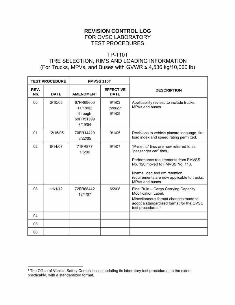
REVISION CONTROL LOG FOR OVSC LABORATORY
TEST PROCEDURES
TP-110T TIRE SELECTION, RIMS AND LOADING INFORMATION
(For Trucks, MPVs, and Buses with GVWR ≤ 4,536 kg/10,000 lb)
TEST PROCEDURE
FMVSS 110T
DESCRIPTION
REV. No.
DATE
AMENDMENT EFFECTIVE
DATE
00
3/10/05
67FR69600
11/18/02
through
69FR51399
8/19/04
9/1/03
through
9/1/05
Applicability revised to include trucks, MPVs and buses.
01
12/15/05
70FR14420
3/22/05
9/1/05 Revisions to vehicle placard language, tire load index and speed rating permitted.
02
8/14/07
71FR877
1/6/06
9/1/07 “P-metric” tires are now referred to as “passenger car” tires. Performance requirements from FMVSS No. 120 moved to FMVSS No. 110. Normal load and rim retention requirements are now applicable to trucks, MPVs and buses.
03
11/1/12
72FR68442
12/4/07
6/2/08 Final Rule – Cargo Carrying Capacity Modification Label.
Miscellaneous format changes made to adopt a standardized format for the OVSC test procedures.¹
04
05
06
¹ The Office of Vehicle Safety Compliance is updating its laboratory test procedures, to the extent practicable, with a standardized format.
1
1. PURPOSE AND APPLICATION
This document is a laboratory test procedure provided by the National Highway Traffic Safety Administration (NHTSA), Office of Vehicle Safety Compliance (OVSC) for the purpose of presenting guidelines for a uniform testing data and information recording format, and providing suggestions for the use of specific equipment and procedures for contracted testing laboratories. The data correspond to specific requirements of the Federal Motor Vehicle Safety Standard(s) (FMVSS). The OVSC test procedures include requirements that are general in scope to provide flexibility for contracted laboratories to perform compliance testing and are not intended to limit or restrain a contractor from developing or utilizing any testing techniques or equipment which will assist in procuring the required compliance test data. These test procedures do not constitute an endorsement or recommendation for use of any particular product or testing method.
Prior to conducting compliance testing, contracted laboratories are required to submit a detailed test procedure to the Contracting Officer's Technical Representative (COTR) to demonstrate concurrence with the OVSC laboratory test procedure and the applicable FMVSS. If any contractor views any part of an OVSC laboratory test procedure to be in conflict with a FMVSS or observes deficiencies in a laboratory test procedure, the contractor is required to advise the COTR and resolve the discrepancy prior to the start of compliance testing or as soon as practicable. The contractor’s test procedure must include a step-by-step description of the methodology and detailed check-off sheets. Detailed check-off sheets shall also be provided for the testing instrumentation including a complete listing of the test equipment with make and model numbers. The list of test equipment shall include instrument accuracy and calibration dates. All equipment shall be calibrated in accordance with the manufacturer’s instructions. There shall be no contradictions between the laboratory test procedure and the contractor’s in-house test procedure. Written approval of the in-house test procedures shall be obtained from the COTR before initiating the compliance test program.
NOTE: The OVSC Laboratory Test Procedures, prepared for the limited purpose of use by independent laboratories under contract to conduct compliance tests for the OVSC, are not rules, regulations or NHTSA interpretations regarding the meaning of a FMVSS. The laboratory test procedures are not intended to limit the requirements of the applicable FMVSS(s). In some cases, the OVSC laboratory test procedures do not include all of the various FMVSS minimum performance requirements. Recognizing applicable test tolerances, the laboratory test procedures may specify test conditions that are less severe than the minimum requirements of the standard. In addition, the laboratory test procedures may be modified by the OVSC at any time without notice, and the COTR may direct or authorize contractors to deviate
2
1. PURPOSE AND APPLICATION....Continued
from these procedures, as long as the tests are performed in a manner consistent with the standard itself and within the scope of the contract. Laboratory test procedures may not be relied upon to create any right or benefit in any person. Therefore, compliance of a vehicle or item of motor vehicle equipment is not necessarily guaranteed if the manufacturer limits its certification tests to those described in the OVSC laboratory test procedures.
2. GENERAL REQUIREMENTS
This Test Procedure applies only to Light Truck Type Vehicles (Multipurpose Passenger Vehicles excluding Motor Homes, Buses and Trucks) with a Gross Vehicle Weight Rating (GVWR) of 4,536 kg or less. This Laboratory Test Procedure is not intended for use in testing recreation vehicles (motor homes and recreation vehicle trailers), trailers, motorcycles or low speed vehicles. Applicable vehicles are to be equipped with tires that meet the requirements of FMVSS 139, New Pneumatic Radial Tires for Light Vehicles, and be equipped with rims that are listed by the manufacturer of the tires as suitable for use with those tires.
The sum of the maximum load ratings of tires fitted to an axle is required to be not less than the gross axle weight rating (GAWR) of the axle system as specified on the vehicle's certification label. If a passenger car tire is used, its load rating is reduced by dividing by 1.10 before calculating the sum. For vehicles equipped with passenger car tires, the vehicle normal load on the tire is not to be greater than the value of 94 percent of the derated load rating at the vehicle manufacturer’s recommended cold inflation pressure for that tire. For vehicles equipped with LT tires, the vehicle normal load on the tire is not to be greater than the value of 94 percent of the load rating at the vehicle manufacturer’s recommended cold inflation pressure for that tire. A single vehicle placard or a vehicle placard and a supplementary tire inflation pressure label must be affixed to each applicable vehicle.
If the weight exceeding the lesser of 1.5 percent of the GVWR or 45.4 kg (100 pounds) is added to the vehicle between final vehicle certification and first retail sale, the car’s capacity weight value on the vehicle placard must be corrected by attaching a load carrying capacity modification label or other method specified.
3
2. GENERAL REQUIREMENTS....Continued Each rim is to be constructed according to the dimensions referred to in S4 of FMVSS 139 that is listed by the manufacturer of the tires for use with those tires and is to be capable of retaining a tire after a rapid loss of inflation pressure at 97 kilometers per hour. Vehicle rims are to be marked appropriately on the outward side of the rim. Each vehicle shall show the size designation and type designation of the rims for the tires installed as original equipment by the vehicle manufacturer on the 49 CFR Part 567 Certification label.
49 CFR 567, Certification, requires that the GVWR is not to be less than the sum of the unloaded vehicle weight, rated cargo load, and 68 kg times the vehicle’s designated seating capacity. However, for school buses, the minimum occupant weight allowance is 54 kg. 49 CFR Part 575 – Consumer Information Regulations, sections 575.6(a)(4) and (5) require each vehicle owner’s manual or other document to provide discussions or statements relating to vehicle labeling, tires and loading. Refer to TP-110P for testing passenger cars and TP-110RV for testing recreation vehicles (motor homes and recreation vehicle trailers) and trailers.
METRIC SYSTEM OF MEASUREMENT Section 5164 of the Omnibus Trade and Competitiveness Act (Pub. L. 100-418) establishes that the metric system of measurement is the preferred system of weights and measures for trade and commerce in the United States. Executive order 12770 directs Federal agencies to comply with the Act by converting regulatory standards to the metric system after September 30, 1992. In a final rule published on March 15, 1990 (60 FR 13639), NHTSA completed the first phase of metrication, converting English measurements in several regulatory standards to the metric system. Since then, metrication has been applied to other regulatory standards (63 FR 28912).
Accordingly, the OVSC laboratory test procedures include revisions to comply with governmental directives in using the metric system. Regulatory standards converted to metric units are required to use metric measurements in the test procedures, whereas standards using English units are allowed to use English measurements or to use English measurements in combination with metric equivalents in parentheses. All final compliance test reports are required to include metric measurements for standards using metrication. NOTE: The methodology for rounding measurement in the test reports shall be made in accordance with ASTM E29-06b, “Standard Practice for Using Significant Digits in Test Data to Determine Conformance with Specifications.”
4
3. SECURITY The contractor shall provide appropriate security measures to protect the OVSC test vehicles and Government Furnished Property (GFP) from unauthorized personnel during the entire compliance testing program. The contractor is financially responsible for any acts of theft and/or vandalism which occur during the storage of test vehicles and GFP. Any security problems which arise shall be reported by telephone to the Industrial Property Manager (IPM), Office of Acquisition Management, within two working days after the incident. A letter containing specific details of the security problem shall be sent to the IPM (with copy to the COTR) within 48 hours.
The contractor shall protect and segregate the data that evolves from compliance testing before and after each vehicle test. No information concerning the vehicle safety compliance testing program shall be released to anyone except the COTR, unless specifically authorized by the COTR or the COTR's Division Chief.
NOTE: No individuals, other than contractor personnel directly involved in the compliance testing program or OVSC personnel, shall be allowed to witness any vehicle or equipment item compliance test or test dummy calibration unless specifically authorized by the COTR.
4. GOOD HOUSEKEEPING
Contractors shall maintain the entire vehicle compliance testing area, test fixtures and instrumentation in a neat, clean and painted condition with test instruments arranged in an orderly manner consistent with good test laboratory housekeeping practices.
5. TEST SCHEDULING AND MONITORING
The contractor shall submit a test schedule to the COTR prior to conducting the first compliance test. Tests shall be completed at intervals as required in the contract. If not specified, the first test shall be conducted within 6 weeks after receiving the first delivered unit. Subsequent tests shall be completed in no longer that 1 week intervals unless otherwise specified by the COTR.
Scheduling of tests shall be adjusted to permit vehicles (or equipment, whichever applies) to be tested to other FMVSSs as may be required by the OVSC. All compliance testing shall be coordinated with the COTR in order to allow monitoring by the COTR and/or other OVSC personnel if desired. The contractor shall submit a monthly test status report and a vehicle status report (if applicable) to the COTR. The vehicle status report shall be submitted until all vehicles are disposed of. The status report forms are provided in the forms section.
6. TEST DATA DISPOSITION
5
The Contractor shall make all vehicle preliminary compliance test data available to the COTR on location within 30 minutes after the test. Final test data, including digital printouts and computer generated plots (if applicable) shall be available to the COTR in accordance with the contract schedule or if not specified within two working days. Additionally, the Contractor shall analyze the preliminary test results as directed by the COTR.
All backup data sheets, strip charts, recordings, plots, technicians’ notes, etc., shall be either sent to the COTR or destroyed at the conclusion of each delivery order, purchase order, etc. The contractor shall protect and segregate the data that evolves from compliance testing before and after each test. TEST DATA LOSS
A. INVALID TEST DESCRIPTION
An invalid compliance test is one, which does not conform precisely to all requirements/specifications of the OVSC Laboratory Test Procedure and Statement of Work applicable to the test.
B. INVALID TEST NOTIFICATION
The Contractor shall notify NHTSA of any test not meeting all requirements/specifications of the OVSC Laboratory Test Procedure and Statement of Work applicable to the test, by telephone, within 24 hours of the test and send written notice to the COTR within 48 hours or the test completion.
C. RETEST NOTIFICATION The Contracting Officer of NHTSA is the only NHTSA official authorized to
notify the Contractor that a retest is required. The retest shall be completed within 2 weeks after receipt of notification by the Contracting Officer that a retest is required.
D. WAIVER OF RETEST
NHTSA, in its sole discretion, reserves the right to waive the retest requirement. This provision shall not constitute a basis for dispute over the NHTSA's waiving or not waiving any requirement.
6. TEST DATA DISPOSITION....Continued
6
E. TEST VEHICLE
NHTSA shall furnish only one vehicle for each test ordered. The Contractor shall furnish the test vehicle required for the retest. The retest vehicle shall be equipped as the original vehicle. The original vehicle used in the invalid test shall remain the property of NHTSA, and the retest vehicle shall remain the property of the Contractor. The Contractor shall retain the retest vehicle for a period not exceeding 180 days if it fails the test. If the retest vehicle passes the test, the Contractor may dispose of it upon notification from the COTR that the test report has been accepted.
F. TEST REPORT
No test report is required for any test that is determined to be invalid unless NHTSA specifically decides, in writing, to require the Contractor to submit such report. The test data from the invalid test must be safeguarded until the data from the retest has been accepted by the COTR. The report and other required deliverables for the retest vehicle are required to be submitted to the COTR within 3 weeks after completion of the retest.
G. DEFAULT
The Contractor is subject to the default and subsequent reprocurement costs for nondelivery of valid or conforming test (pursuant to the Termination For Default clause in the contract).
H. NHTSA'S RIGHTS
None of the requirements herein stated shall diminish or modify the rights of NHTSA to determine that any test submitted by the Contractor does not conform precisely to all requirements/specifications of the OVSC Laboratory Test Procedure and Statement of Work applicable to the test.
7. GOVERNMENT FURNISHED PROPERTY (GFP)
GFP consist of test vehicles, test equipment and instrumentation. The GFP is authorized by contractual agreement. The contractor is responsible for the following.
7. GOVERNMENT FURNISHED PROPERTY (GFP)....Continued
7
A. ACCEPTANCE OF TEST VEHICLES The contractor has the responsibility of accepting each GFP test vehicle whether delivered by a new vehicle dealership or another vehicle transporter. In both instances, the contractor acts on behalf of the OVSC when signing an acceptance of the GFP test vehicle delivery order. When a GFP vehicle is delivered, the contractor must verify:
1. All options listed on the "window sticker" are present on the test vehicle.
2. Tires and wheel rims are new and the same as listed. 3. There are no dents or other interior or exterior flaws in the vehicle body. 4. The vehicle has been properly prepared and is in running condition. 5. The glove box contains an owner's manual, warranty document, consumer
information, and extra set of keys. 6. Proper fuel filler cap is supplied on the test vehicle. 7. Spare tire, jack, lug wrench and tool kit (if applicable) is located in the
vehicle cargo area. 8. The VIN (vehicle identification number) on the vehicle condition report
matches the VIN on the vehicle. 9. The vehicle is equipped as specified by the COTR.
A Vehicle Condition form will be supplied to the contractor by the COTR when the test vehicle is transferred from a new vehicle dealership or between test contracts. The upper half of the form is used to describe the vehicle as initially accepted. The lower half of the Vehicle Condition form provides space for a detailed description of the post-test condition. The contractor must complete a Vehicle Condition form for each vehicle and deliver it to the COTR with the Final Test Report or the report will NOT be accepted for payment. If the test vehicle is delivered by a government contracted transporter, the contractor should check for damage which may have occurred during transit. GFP vehicle(s) shall not be driven by the contractor on public roadways unless authorized by the COTR.
7. GOVERNMENT FURNISHED PROPERTY (GFP)....Continued
8
B. TEST EQUIPMENT AND INSTRUMENTATION The contractor has the responsibility of accepting GFP test equipment and instrumentation delivered to the contractor. The contractor acts on behalf of the OVSC when signing an acceptance of the GFP test equipment and instrumentation delivery order. When GFP test equipment and instrumentation is delivered, the contractor must:
1. Verify all partial and sub-component quantities as per the packaging document
2. Verify physical condition of all equipment and instrumentation (inspect for
damage) 3. Verify functional condition of all equipment and instrumentation 4. Store in a clean, organized, secure, and environmentally controlled area
C. NOTIFICATION OF COTR
The COTR must be notified within 24 hours after a vehicle (and/or equipment item) has been delivered. In addition, if any discrepancy or damage is found at the time of delivery, a copy of the Vehicle Condition form shall be sent to the COTR immediately.
8. CALIBRATION OF TEST INSTRUMENTS
Before the contractor initiates the safety compliance test program, a test instrumentation calibration system will be implemented and maintained in accordance with established calibration practices. The calibration system shall include the following as a minimum:
A. Standards for calibrating the measuring and test equipment shall be stored
and used under appropriate environmental conditions to assure their accuracy and stability.
B. All measuring instruments and standards shall be calibrated by the
Contractor, or a commercial facility, against a higher order standard at periodic intervals not exceeding 12 months for instruments and 12 months for the calibration standards except for static types of measuring devices such as rulers, weights, etc., which shall be calibrated at periodic intervals not to
8. CALIBRATION OF TEST INSTRUMENTS ...Continued

9
exceed two years. Records, showing the calibration traceability to the National Institute of Standards and Technology (NIST), shall be maintained for all measuring and test equipment.
C. All measuring and test equipment and measuring standards shall be labeled with the following information:
(1) Date of calibration
(2) Date of next scheduled calibration
(3) Name of the technician who calibrated the equipment
D. A written calibration procedure shall be provided by the Contractor, which includes as a minimum the following information for all measurement and test equipment:
(1) Type of equipment, manufacturer, model number, etc. (2) Measurement range (3) Accuracy (4) Calibration interval
(5) Type of standard used to calibrate the equipment (calibration traceability of the standard must be evident).
(6) The actual procedures and forms used to perform the calibrations.
E. Records of calibration for all test instrumentation shall be kept by the
Contractor in a manner that assures the maintenance of established calibration schedules.
F. All such records shall be readily available for inspection when requested by
the COTR. The calibration system shall need the acceptance of the COTR before vehicle safety compliance testing commences.
G. Test equipment shall receive a system functional check out using a known
test input immediately before and after the test. This check shall be recorded by the test technician(s) and submitted with the final report.
8. CALIBRATION OF TEST INSTRUMENTS ...Continued
10
H. The Contractor may be directed by NHTSA to evaluate its data acquisition system.
Further guidance is provided in the International Standard ISO 10012-1, “Quality Assurance Requirements for Measuring Equipment” and American National Standard ANSI/NCSL Z540-1, “Calibration Laboratories and Measuring and Test Equipment - General Requirements.” NOTE: In the event of a failure to meet the standard’s minimum performance requirements, additional calibration checks of some critically sensitive test equipment and instrumentation may be required for verification of accuracy. The necessity for the calibration will be at the COTR’s discretion and will be performed without additional cost.
9. SUGGESTED TEST EQUIPMENT
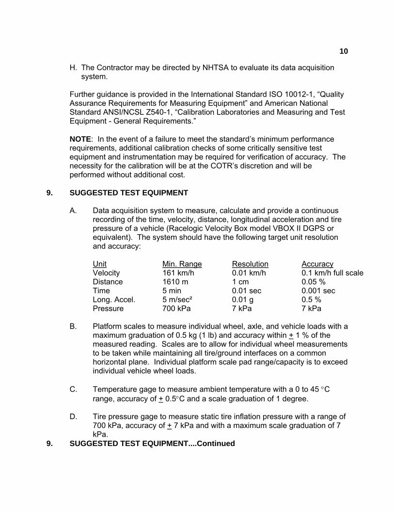
A. Data acquisition system to measure, calculate and provide a continuous recording of the time, velocity, distance, longitudinal acceleration and tire pressure of a vehicle (Racelogic Velocity Box model VBOX II DGPS or equivalent). The system should have the following target unit resolution and accuracy:
Unit Min. Range Resolution Accuracy
Velocity 161 km/h 0.01 km/h 0.1 km/h full scale Distance 1610 m 1 cm 0.05 % Time 5 min 0.01 sec 0.001 sec Long. Accel. 5 m/sec² 0.01 g 0.5 % Pressure 700 kPa 7 kPa 7 kPa
B. Platform scales to measure individual wheel, axle, and vehicle loads with a maximum graduation of 0.5 kg (1 lb) and accuracy within + 1 % of the measured reading. Scales are to allow for individual wheel measurements to be taken while maintaining all tire/ground interfaces on a common horizontal plane. Individual platform scale pad range/capacity is to exceed individual vehicle wheel loads.
C. Temperature gage to measure ambient temperature with a 0 to 45 C
range, accuracy of + 0.5C and a scale graduation of 1 degree. D. Tire pressure gage to measure static tire inflation pressure with a range of
700 kPa, accuracy of + 7 kPa and with a maximum scale graduation of 7 kPa.
9. SUGGESTED TEST EQUIPMENT....Continued
11
E. Anemometer to measure wind speed. Ten m/s range with + 1 m/s accuracy at 5 m/s and scale graduation of 1 m/s.
F. Pressure Transducer to measure tire inflation pressure while test vehicle
is in motion with a range of 700 kPa, accuracy of + 7 kPa and with a maximum scale graduation of 7 kPa.
G. Laser Level with Digital Protractor Inclinometer to measure road surface
grade and for leveling weight scales during vehicle load analyses with 360 degree range and +0.1 degree accuracy and 0.1 degree resolution.
H. Tape measure or ruler to measure rim dimensions with 1 m range and 1.0
mm scale graduation. I. Latest edition of approved Tire and Rim reference manual as identified in
FMVSS No. 110. 10. PHOTOGRAPHIC DOCUMENTATION
DIGITAL PHOTOGRAPHS The contractor shall take digital photographs of the pretest, test execution and post test conditions. Photographs shall be taken in color and contain clear images. A tag, label or placard identifying the test item, NHTSA number (if applicable) and date shall appear in each photograph and must be legible. Each photograph shall be labeled as to the subject matter. The required resolution for digital photographs is a minimum of 1,600 x 1,200 pixels. Digital photographs are required to be created and in a JPG format. Glare or light from any illuminated or reflective surface shall be minimized while taking photographs. The test setup and equipment used in all tests shall be photographed for the record before and at prescribed time periods during testing. The test reports shall include enough photographs to describe the testing in detailed and shall be organized in a logical succession of consecutive pictures. The digital photographs shall be included in the test report as 203 mm x 254 mm or 215.9 mm x 279 mm (8 x 10 or 8½ x 11 inch) pictures. All photographs are required to be included in the test report in the event of a test failure. Any failure must be photographed at various angles to assure complete coverage. Upon request, the photographs shall be sent to the COTR on a CD or DVD and saved in a “read only” format to ensure that the digital photographs are the exact pictures taken during testing and have not been altered from the original condition.
10. PHOTOGRAPHIC DOCUMENTATION ....Continued
12
PHOTOGRAPHIC VIEWS As a minimum the following test photographs shall be included in each vehicle final test report, submitted by the contractor:
A. 3/4 frontal view from left side of vehicle B. 3/4 rear view from right side of vehicle C. Vehicle's Certification Label D. Alterer’s Label (if attached) E. Vehicle Placard F. Tire Inflation Pressure Label (if attached) G. Load Carrying Capacity Modification Permanent Label (if attached) H. Monroney Label (if attached) I. Distributor/Dealer option/accessory label (if attached) J. Tire showing brand and model K. Tire showing size, load index and speed symbol L. Tire showing load rating and inflation pressure
M. Tire showing serial number N. Rim contour for full width of rim cross section O. Rim markings P. Close-up of test instrumentation used for tire blow-out Q. Close-up of blow-out tire with ruler next to hole
R. Close-up of interior seating position simulated occupant ballast S. Close-up of interior cargo simulated ballast T. View of vehicle on weight scales U. Pertinent Owner’s manual pages V. Close-up of all test failure areas and components
11. DEFINITIONS
ACCESSORY WEIGHT The combined weight (in excess of those standard items which may be replaced) of automatic transmission, power steering, power brakes, power windows, power seats, radio, and heater, to the extent that these items are available as factory-installed equipment (whether installed or not). CERTIFICATION LABEL
A label required to be affixed to every motor vehicle in accordance with Part 567, Certification.
11. DEFINITIONS....Continued
CURB WEIGHT
13
The weight of a motor vehicle with standard equipment including the maximum capacity of fuel, oil, and coolant, and, if so equipped, air conditioning and additional weight of optional engine. DOT TIRE IDENTIFICATION NUMBER
Number appearing on the sidewall of the tire near the rim required by 49 CFR Part 574.5 which identifies the manufacturer’s identification mark, tire size, tire type code and date of manufacture.
DOT SYMBOL
The letters "DOT" are part of the DOT serial number. This is the manufacturer's certification that the tire or rim meets or exceeds the requirements of FMVSS Nos. 110 and 139. GAWR
The Gross Axle Weight Rating (GAWR) means the value specified by the vehicle manufacturer as the load-carrying capacity of a single axle system, as measured at the tire-ground interfaces. GVWR The Gross Vehicle Weight Rating (GVWR) means the value specified by the manufacturer as the loaded weight of a single vehicle.
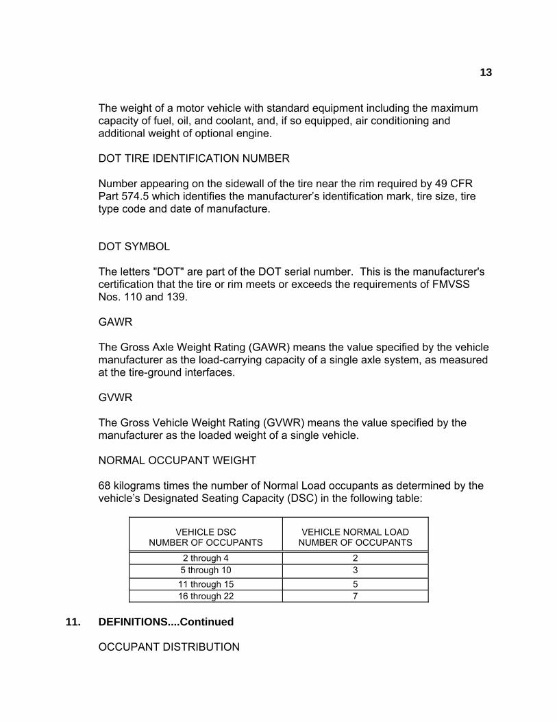
NORMAL OCCUPANT WEIGHT
68 kilograms times the number of Normal Load occupants as determined by the vehicle’s Designated Seating Capacity (DSC) in the following table:
VEHICLE DSC NUMBER OF OCCUPANTS
VEHICLE NORMAL LOAD NUMBER OF OCCUPANTS
2 through 4 2 5 through 10 3
11 through 15 5 16 through 22 7
11. DEFINITIONS....Continued
OCCUPANT DISTRIBUTION
14
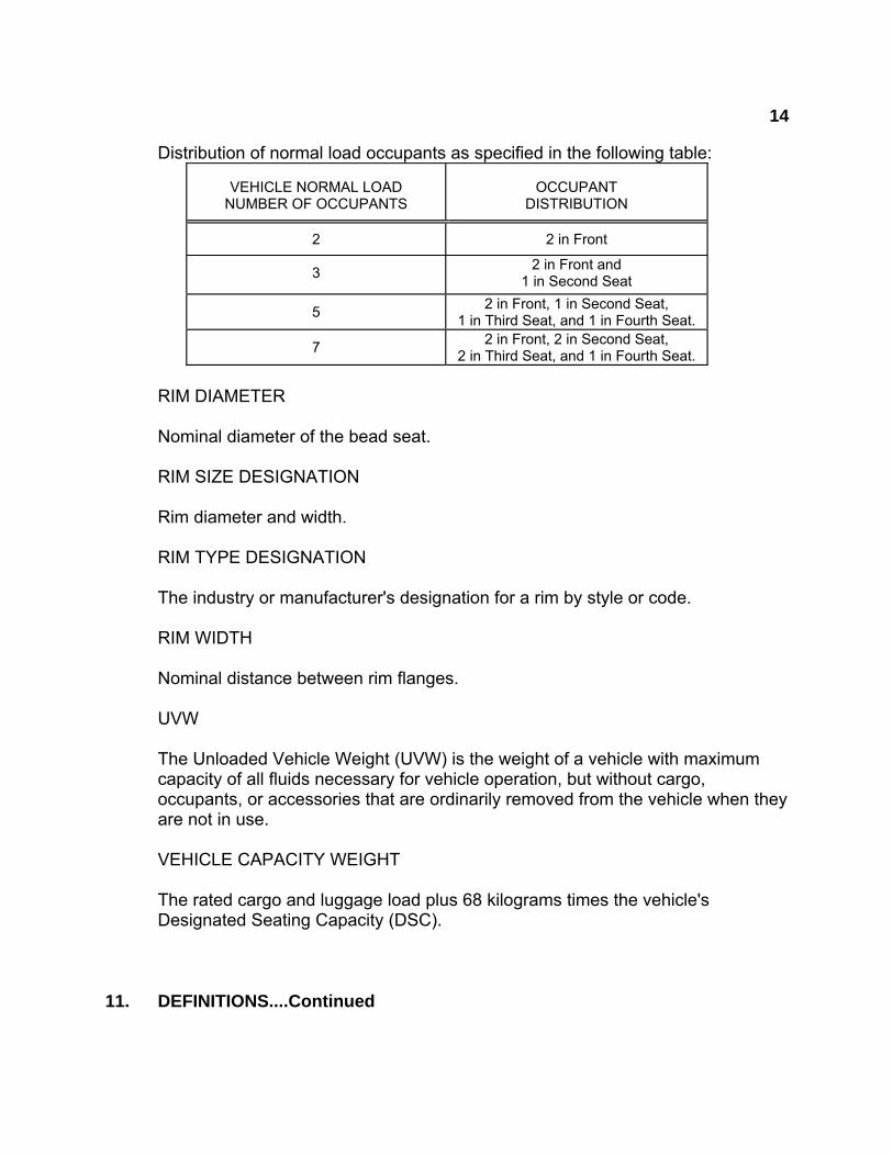
Distribution of normal load occupants as specified in the following table:
VEHICLE NORMAL LOAD NUMBER OF OCCUPANTS
OCCUPANT DISTRIBUTION
2 2 in Front
3 2 in Front and
1 in Second Seat
5 2 in Front, 1 in Second Seat,
1 in Third Seat, and 1 in Fourth Seat.
7 2 in Front, 2 in Second Seat,
2 in Third Seat, and 1 in Fourth Seat.
RIM DIAMETER
Nominal diameter of the bead seat.
RIM SIZE DESIGNATION
Rim diameter and width.
RIM TYPE DESIGNATION
The industry or manufacturer's designation for a rim by style or code.
RIM WIDTH
Nominal distance between rim flanges.
UVW
The Unloaded Vehicle Weight (UVW) is the weight of a vehicle with maximum capacity of all fluids necessary for vehicle operation, but without cargo, occupants, or accessories that are ordinarily removed from the vehicle when they are not in use. VEHICLE CAPACITY WEIGHT
The rated cargo and luggage load plus 68 kilograms times the vehicle's Designated Seating Capacity (DSC).
11. DEFINITIONS....Continued
15
VEHICLE NORMAL LOAD ON THE TIRE The vehicle normal load on the tire means that load on an individual tire that is determined by distributing to each axle its share of the curb weight, accessory weight, and normal occupant weight and dividing by 2.
12. PRETEST REQUIREMENTS
IN-HOUSE COMPLIANCE TEST PROCEDURE
Prior to conducting any compliance tests, contractors are required to submit a detailed in-house compliance test procedure and equipment list to the COTR which includes a step-by-step description of the methodology to be used and a detailed check-off list. Written approval will be obtained from the COTR before commencing testing so that all parties are in agreement. The contractor's test procedure will contain a complete listing of test equipment and a detailed check-off list. There will be no contradiction between the OVSC Laboratory Test Procedure and the contractor's in-house test procedure. The list of test equipment will include instrument accuracy and calibration dates. GENERAL TEST CONDITIONS A. For the execution of this test the Maximum Loaded Vehicle Weight is the
sum of the Unloaded Vehicle Weight or Curb Weight and the Vehicle Capacity Weight. The Vehicle Normal Load Weight is the sum of the Curb Weight and the Normal Occupant Weight. For this test, the unloaded vehicle weight and curb weight are considered equal and are the weight of the test vehicle as delivered including installed accessories and options, and the maximum capacity of fuel, oil and coolant.
B. For loading of simulated occupant ballast each adjustable seat should be
positioned to its mid forward-to-aft and mid up-to-down seat position adjustment ranges.
C. Adult simulated occupant load ballast for each designated seating position
is 68 kg (150 lb). 54 kg (120 lb) of ballast should be placed on the seat and 14 kg (30 lb) should be placed on the floor directly in front of the respective seating position. Student simulated occupant load ballast for each designated seating position is 54 kg (120lb). Ballast for students should be placed as directed by the COTR.
12. PRETEST REQUIREMENTS....Continued
16
D. All measurements, weighing and dynamic portions of the test should be performed with ambient air temperatures between 0C and 38C.
E. The deflated tire retention test should be performed on a straight, dry and
paved surface with grades in any direction not exceeding 1 % and a wind velocity not exceeding 5 m/s.
F. At the start of the deflated tire retention test the fuel tank should be at
least 90 percent full.
G. The driver and observer (if present) should be restrained with the vehicle by properly adjusted seat belt, head restraint, and any protective device included in the vehicle during the deflated tire retention test. Other protective devices are optional to the testing agent.
13. COMPLIANCE TEST EXECUTION
Personnel supervising and/or performing the compliance test program should be thoroughly familiar with the requirements, test conditions, and equipment for the test to be conducted. Testing will be accomplished as indicated below. Test personnel should make note of all discrepancies and deviations from the applicable FMVSS and the Laboratory Test Procedure.
13.1 TEST VEHICLE INFORMATION (Data Sheet 1)
Inspect the vehicle, Monroney label and other affixed labels and record test vehicle information as required on data sheet 1. Identify options, accessories, and equipment installed on the vehicle at the time of test. From the optional and accessory equipment list developed, if identified on the vehicle labeling, make note of the equipment installed by the distributor or dealer after the vehicle was completed by the OEM.
13.2 VEHICLE TIRE IDENTIFICATION AND LOAD LIMITS (Data Sheet 2)
A. Visually inspect all the tires on the vehicle including the spare tire. If all the tires are not the same make, model and size, explain under REMARKS, and contact COTR immediately.
B. Record the tire sidewall information for the right front tire and the spare tire
(if different). If the front axle tire size is different than the rear axle tire size also record the sidewall information for the left rear tire.
C. Record the serial numbers from all vehicle tires.

17
D. Verify that all tires are marked with “DOT” certifying compliance to applicable tire performance FMVSS.
E. Record the GAWR for each axle from the vehicle's certification label.
Multiply the number of tires on the axle times the maximum load rating found on the tire. If the vehicle is equipped with passenger car tires, the maximum load rating is reduced by dividing by 1.10. If the vehicle is equipped with dual tires, the maximum load rating for dual tires should be used.
F. Determine and report as PASS or FAIL. Verify that the tires are marked
with “DOT” and the sum of the tire maximum load ratings of the tires on each axle is equal to or greater than the respective axle’s GAWR.
13.3 VEHICLE RIM IDENTIFICATION (Data Sheet 3)
A. Remove the right front wheel from the vehicle. Also, remove the left rear
wheel from the vehicle if the left rear wheel is a different size or model than the right front wheel.
B. For each wheel removed from the vehicle in step A remove the tire from
its rim.
C. Visually inspect each rim. Verify that each rim is marked with the following information. If the date is done by symbol, contact the COTR to obtain how the month, day, and year or the month and year are depicted by the symbol.
A designation which indicates the source of rims's published nominal
dimensions, as follows:
T - The Tire and Rim Association E - The European Tyre and Rim Technical Organization J - Japan Automobile Tire Manufacturers Association, Inc. L - ABPA (Brazil), a.k.a. Associacao Latino Americana De Pneus Aros. F - Tire and Rim Engineering Data Committee of South Africa (Tredco) S - Scandinavian Tire and Rim Organization (STRO) A - The Tyre and Rim Association of Australia I - Indian Tyre Technical Advisory Committee (ITTAC)
R - Argentine Institute of Rationalization of Materials, a.k.a. Instituto Argentino de Racionalizacion de Materiales, (ARAM) N - Independent listing pursuant to S4.1 of FMVSS No. 139 or S5.1 of
FMVSS No. 119
Rim Size Designation.

18
EXAMPLE: 20 x 5.50 or 20 x 5.5
The Symbol DOT. Manufacturer's certification that rim complies with all
applicable FMVSS.
Manufacturer's Name, Trademark, or Symbol.
The month, day, and year or the month and year of manufacture, expressed either numerically or by use of a symbol.
EXAMPLE: September 4, 2001 may be expressed numerically as: “90401”, “904, 01” or “01, 904”; “September 2001” may be expressed numerically as: “901”, “9, 01” or “01, 9”.
Any manufacturer that elects to express the date of manufacture by
means of a symbol is to notify NHTSA in writing.
D. Identify if the lettering is impressed or embossed (stamped or raised) and if it is legible. Verify that all markings are a minimum of 3 millimeters in height.
E. Verify that the source of the published dimensions, rim size and “DOT”
markings appear on the outward side of the rim.
F. Measure the rim width and diameter. Verify that the rim measured dimensions are the same as the rim stamped dimensions.
G. Verify that installed rim size and contour at each wheel position is suitable
for the corresponding installed tire by comparing rim dimensions stamped and/or measured with those indicated in the most recent tire and rim reference manual.
H. Replace tire(s) on rim(s), balance, and return vehicle to pretest condition.
I. Determine and report as Pass or Fail. Installed rims are to be suitable for
installed tires and properly marked.
19
13.4 VEHICLE PLACARD, TIRE INFLATION PRESSURE LABEL, LOAD CARRYING CAPACITY MODIFICATION LABEL, AND OTHER LABELS (Data Sheet 4) A. Record location of the vehicle certification label, vehicle placard, and if
attached, the tire inflation pressure label, the load carrying capacity modification label, Monroney label, alterer’s label, and/or separate distributor/dealer optional equipment label. The certification label is to be affixed to the hinge pillar, door-latch post, or the door edge that meets the door-latch post, next to the driver’s seating position. The vehicle placard, and if provided, the tire inflation pressure label is to be affixed to the driver’s side B-pillar. For further labeling location guidelines refer to Part 567 and FMVSS No. 110.
B. Compare the Vehicle Placard and, if attached, the Tire Inflation
Pressure Label and the Load Carrying Capacity Modification Label formats to the sample formats provided on data sheet 4 and verify that they are exactly the same and the text is in the English language. While comparing label formats review the labeling notes provided below the sample labels and note any discrepancies.
C. Document the information provided on the vehicle placard and tire inflation
pressure label including combined weight of occupants and cargo (vehicle capacity weight), seating capacity, tire size(s) and cold tire pressure(s).
D. Compare the actual number of seating positions (belted positions) with the
placard number of seating positions.
E. Compare the vehicle installed tire size(s) with the tire size(s) labeled on the vehicle placard and, if provided the tire inflation pressure label.
F. Verify that the labeled cold tire inflation pressures are equal to or less than
the maximum tire inflation pressures marked on the sidewall of the installed tires.
G. Document the tire size and rim size information provided on the
certification label. Verify that the tire size(s) listed on the vehicle placard and, if provided the tire inflation pressure label are also listed on the certification label.
H. Verify that the labeled rim(s) and tire size(s) documented in paragraph G
are suitable for each other by referencing an approved tire and rim reference manual.

20
I. Document the information provided on the load carrying capacity modification label (if provided) including the amount the vehicle placard load carry capacity is reduced. Measure and document the label print size (height) and distance from vehicle placard. J. If the test vehicle has an attached Monroney label, record the tire size
listed on the label. Make note if the tire size specified on the label is the same size as is installed on the vehicle.
K. If the vehicle has an affixed separate distributor/dealer optional equipment
label, document listed equipment. L. Record the vehicle’s GAWRs. Determine the tire load ratings for the labeled
tires at the recommended inflation pressure by referring to the approved tire and rim reference manual. If the vehicle is labeled with passenger car tires, the load carrying capacity is reduced by dividing by 1.10. If the vehicle is labeled with dual tires, the load capacity for dual tires should be used. Multiply the tire load rating times the number of tires on each axle. Verify that the sum of the load ratings for the tires on any axle is greater than or equal to the GAWR for that axle.
M. Determine and report as Pass or Fail. The Vehicle Placard, and, if
provided, the Tire Inflation Pressure Label, and the Load Carrying Capacity Modification Label are to be located as required, permanent, legible, and contain the information specified in the format provided. The labeled tire inflation pressure is to be equal to or less than the installed tire’s maximum sidewall inflation pressure. The certification label should provide an appropriate rim size designation for the vehicle placard or tire inflation pressure label specified tires. The sum of the load ratings for the labeled tires on an axle, at the recommended inflation pressure, is to be equal to or greater than the respective axle’s GAWR.
13.5 UNLOADED VEHICLE WEIGHT or CURB WEIGHT, NORMAL LOAD WEIGHT,
AND MAXIMUM LOAD WEIGHT (Data Sheet 5) 49 CFR 567, Certification, requires that the Gross Vehicle Weight Rating
(GVWR) is not to be less than the sum of the unloaded vehicle weight, rated cargo load, and 68 kg times the vehicle’s designated seating capacity.
A. Record certified GVWR, GAWRs, and tire load ratings at manufacturer
recommended inflation pressure in the vehicle weight distribution table. If a passenger car tire is installed on a multipurpose vehicle (MPV), truck or bus, the tire’s load rating is reduced by dividing by 1.10.
B. Check all vehicle fluids and fill to manufacturer’s recommended capacity.

21
C. Adjust tire pressures of all tires to that appearing on the vehicle placard or
tire inflation pressure label.
D. Position appropriate scales on level surface in laboratory test area. Using a laser and digital protractor inclinometer (or equivalent) ensure leveling of scales front-to-back, side-to-side and corner-to-corner. Adjust scales to obtain tire/ground load measurements on a common horizontal plane.
E. Weigh and record the vehicle’s Unloaded Vehicle Weight or Curb
Weight including weight of each wheel position and calculate axle and vehicle weights.
F. Determine the number of occupants and occupant distribution for vehicle
normal load as specified in section 11, Definitions, of this test procedure. Calculate and record the total normal occupant load.
G. Ballast the vehicle to simulate a normal occupant load by placing
appropriate ballast in each of the respective normal load seating positions. For proper seat adjustment and ballast placement refer to the general test conditions in section 12. Record the weight of each wheel position and calculate the Vehicle Normal Load on the Axles.
H. Calculate and record the “Vehicle Normal Load on the Tire” and ”Value of
94% of the Load Rating at the Vehicle Manufacturer’s Recommended Cold Inflation Pressure” as instructed on the Data Sheet 5 (Section B (5) and (6)). Verify that the Vehicle Normal Load on the Tire for each axle is not greater than the Value of 94% of the Load Rating at the Vehicle Manufacturer’s Recommended Cold Inflation Pressure.
I. Record total seating capacity and occupant distribution from the vehicle
placard. Calculate and record weight of full occupant load.
J. Ballast the vehicle to simulate a full occupant load by placing appropriate ballast in each of the designated seating positions. For proper seat adjustment and ballast placement refer to the general test conditions in section 12. Record the weight of each wheel position and calculate the Vehicle Weight with Full Occupant Load. The full occupant load for a school bus is determined by using 68 kg for the driver and 54 kg for each student occupant.
K. Calculate the vehicle’s luggage/cargo load as instructed on Data Sheet 5
(Section D. (1)–(5)). L. Ballast the vehicle to simulate the luggage/cargo load calculated above.

22
The ballast should be placed in the appropriate cargo loading area(s) and distributed uniformly fore/aft and side/side. If the vehicle has more than one cargo area (trunk, behind the rear seat, roof rack, etc.) consult the owner’s manual and the COTR for further guidance concerning cargo placement. Record the weight of each wheel position and calculate the vehicle’s Maximum Load.
M. Verify that the tire load ratings, axle ratings (GAWR), and vehicle rating
(GVWR) are not exceeded under any of the documented load conditions. If any of the above ratings are exceeded, indicate “YES” in the respective “Overload” column on Data Sheet 5 (2 of 2), and notify the COTR immediately.
N. Determine and report as Pass or Fail. The GVWR is not to be less than
the sum of the unloaded vehicle weight, rated cargo load, and 68 kg times the vehicle’s designated seating capacity. However, for school buses, the minimum occupant weight allowance is 54 kg.
13.6 DEFLATED TIRE RETENTION (Data Sheet 6)
A. Adjust tire pressure of all tires to the vehicle placard cold tire inflation pressure. Record final adjusted tire inflation pressures.
B. Load vehicle to the maximum loaded vehicle weight and corresponding
vehicle maximum load on each axle as obtained and recorded on Data Sheet 5 (Section D.(6)). of this test procedure. To obtain this load the vehicle is loaded with required test instrumentation, full fluids, a driver and simulated occupant/cargo ballast. Record weight by axle and wheel position.
C. Secure all added items and ballast in vehicle.
D. With the vehicle traveling in a straight line at 97 kmph (+ 0 kmph, - 2
kmph), simulate the rapid loss of inflation pressure in the left front tire through an opening at least equal to a 1.3 cm diameter hole.
Upon initial release of air, bring the vehicle to a stop using the most rapid constant deceleration rate attainable not exceeding 2.5 m/sec² (8 ft/sec²)
with no wheel skid. Record vehicle speed, tire pressure, deceleration, stopping distance (distance traveled after initial release of air), distance of uncontrolled deviation from a straight line, and test conditions. Permanent, continuous recording is required for time, vehicle speed, tire pressure and deceleration rate.
E. With the vehicle remaining in the stopped position, photographically record
23
and verbally describe all separation of the tire bead from the rim flange on both inboard and outboard sides of the rim under test. Rotation of the wheel to permit access to upper inboard positions of the tire should be done after outboard and lower inboard information is recorded.
F. Return the vehicle to pretest condition. Repeat Items A through E, using
the right rear tire position (or other as directed). G. Determine and report a pass or fail for each wheel position tested. Each
rim should be capable of retaining its respective tire during a rapid loss of inflation pressure at 97 kilometers per hour and until the vehicle can be stopped with a controlled braking application.
13.7 OWNER’S MANUAL REQUIREMENTS (Data Sheet 6)
Review the vehicle owner’s manual or other manufacturer provided document if an owner’s manual is not provided, and verify that the information as specified on data sheet 6 is discussed and/or stated. The basis of these requirements is Part 575.6. Copy applicable pages of the owner’s manual or other document for inclusion in the Final Test Report. Determine and report as Pass or Fail.
14. POST TEST REQUIREMENTS
Remove all ballast from vehicle. Verify all data sheets have been completed and all photographs have been taken. Return vehicle to its pretest condition. After the required tests are completed, the contractor shall: A. Verify all data sheets complete and photographs taken,
B. Complete Data Summary Sheets,
C. Complete the Vehicle Condition report form including a word description of its
post test condition,
D. Copy applicable pages of the vehicle Owner’s Manual for attachment to the final test report,
E. Remove all instrumentation from vehicle. Return vehicle to its pretest
condition.
F. Move the test vehicle to a secure area,
G. Place all original records in a secure and organized file awaiting test data disposition.
15. REPORTS
24
15.1. MONTHLY STATUS REPORTS
The contractor will submit a monthly Test Status Report and a Vehicle Status Report to the COTR. The Vehicle Status report will be submitted until all vehicles are disposed of. Samples of the required reports are found in the report forms section.
15.2. APPARENT NONCOMPLIANCE
Any indication of a test failure shall be communicated by telephone to the COTR within 24 hours with written notification mailed within 48 hours (Saturdays and Sundays excluded). A Notice of Test Failure (see report forms section) with a copy of the particular compliance test data sheet(s) and preliminary data plot(s) shall be included. In the event of a test failure, a post test calibration check of some critically sensitive test equipment and instrumentation may be required for verification of accuracy. The necessity for the calibration shall be at the COTR's discretion and shall be performed without additional costs to the OVSC.
15.3. FINAL TEST REPORTS 15.3.1 COPIES
In the case of an apparent test failure, seven paper copies and 2 CD electronic copies in both Word and pdf formats of the Final Test Report shall be submitted to the COTR for acceptance within three weeks of test completion. The Final Test Report format to be used by all contractors can be found in the "Report Section". Where there has been no indication of an apparent noncompliance, three paper copies and 2 CD electronic copies in both Word and pdf formats of each Final Test Report shall be submitted to the COTR for acceptance within three weeks of test completion. No payment of contractor's invoices for conducting compliance tests will be made prior to the Final Test Report acceptance by the COTR. Contractors are requested to NOT submit invoices before the COTR is provided with copies of the Final Test Report.
Contractors are required to submit the first Final Test Report in draft form within one week after the compliance test is conducted. The contractor and the COTR will then be able to discuss the details of both test conduct and report content early in the compliance test program. Contractors are required to PROOF READ all Final Test Reports before submittal to the COTR. The OVSC will not act as a report quality control office for contractors. Reports containing a significant
15. REPORTS....Continued
25
number of errors will be returned to the contractor for correction, and a "hold" will be placed on invoice payment for the particular test.
15.3.2 REQUIREMENTS
The Final Test Report and associated documentation (including photographs) are relied upon as the chronicle of the compliance test. The Final Test Report will be released to the public domain after review and acceptance by the COTR. For these reasons, each final report must be a complete document capable of standing by itself. The contractor should use DETAILED descriptions of all compliance test events. Any events that are not directly associated with the standard but are of technical interest should also be included. The contractor should include as much DETAIL as possible in the report. Instructions for the preparation of the first three pages of the final test report are provided for standardization.
15.3.3 FIRST THREE PAGES
A. FRONT COVER
A heavy paperback cover (or transparency) will be provided for the protection of the final report. The information required on the cover is as follows:
(1) Final Report Number such as 110-ABC-0X-001, where –
110 is the FMVSS tested ABC are the initials for the laboratory 0X is the Fiscal Year of the test program 001 is the Group Number (001 for the 1st test,
002 for the 2nd test, etc.)
(2) Final Report Title And Subtitle such as SAFETY COMPLIANCE TESTING FOR FMVSS 110 Tire Selection and Rims * * * * * * * * * * * * * * * * ABC Motor Company 200X Saferider 4-door sedan NHTSA No. CX0401
26
15. REPORTS....Continued
(3) Contractor's Name and Address such as COMPLIANCE TESTING LABORATORIES, INC. 4335 West Dearborn Street Detroit, Michigan 48090-1234
NOTE: DOT SYMBOL WILL BE PLACED BETWEEN ITEMS (3) AND (4)
(4) Date of Final Report completion (5) The words "FINAL REPORT"
(6) The sponsoring agency's name and address as follows
U. S. DEPARTMENT OF TRANSPORTATION National Highway Traffic Safety Administration Enforcement Office of Vehicle Safety Compliance Mail Code: NVS-220 1200 New Jersey Avenue, S.E. Washington, DC 20590

27
15. REPORTS....Continued
B. FIRST PAGE AFTER FRONT COVER
When a contract test laboratory is reporting, a disclaimer statement and an acceptance signature block for the COTR shall be provided as follows:
This publication is distributed by the National Highway Traffic Safety Administration in the interest of information exchange. Opinions, findings and conclusions expressed in this publication are those of the author(s) and not necessarily those of the Department of Transportation or the National Highway Traffic Safety Administration. The United States Government assumes no liability for its contents or use thereof. If trade or manufacturers' names or products are mentioned, it is only because they are considered essential to the object of the publication and should not be construed as an endorsement.
Prepared By: ______________________________
Approved By: ______________________________*
Approval Date: _____________________________*
FINAL REPORT ACCEPTANCE BY OVSC:*
Accepted By: ______________________________
Acceptance Date: ___________________________
* These lines not required when OVSC staff writes the Test Report 15. REPORTS....Continued
28
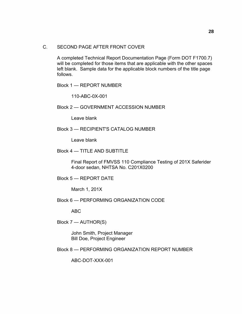
C. SECOND PAGE AFTER FRONT COVER
A completed Technical Report Documentation Page (Form DOT F1700.7) will be completed for those items that are applicable with the other spaces left blank. Sample data for the applicable block numbers of the title page follows.
Block 1 — REPORT NUMBER
110-ABC-0X-001
Block 2 — GOVERNMENT ACCESSION NUMBER
Leave blank
Block 3 — RECIPIENT'S CATALOG NUMBER
Leave blank
Block 4 — TITLE AND SUBTITLE
Final Report of FMVSS 110 Compliance Testing of 201X Saferider 4-door sedan, NHTSA No. C201X0200
Block 5 — REPORT DATE
March 1, 201X
Block 6 — PERFORMING ORGANIZATION CODE
ABC
Block 7 — AUTHOR(S)
John Smith, Project Manager Bill Doe, Project Engineer
Block 8 — PERFORMING ORGANIZATION REPORT NUMBER
ABC-DOT-XXX-001
29
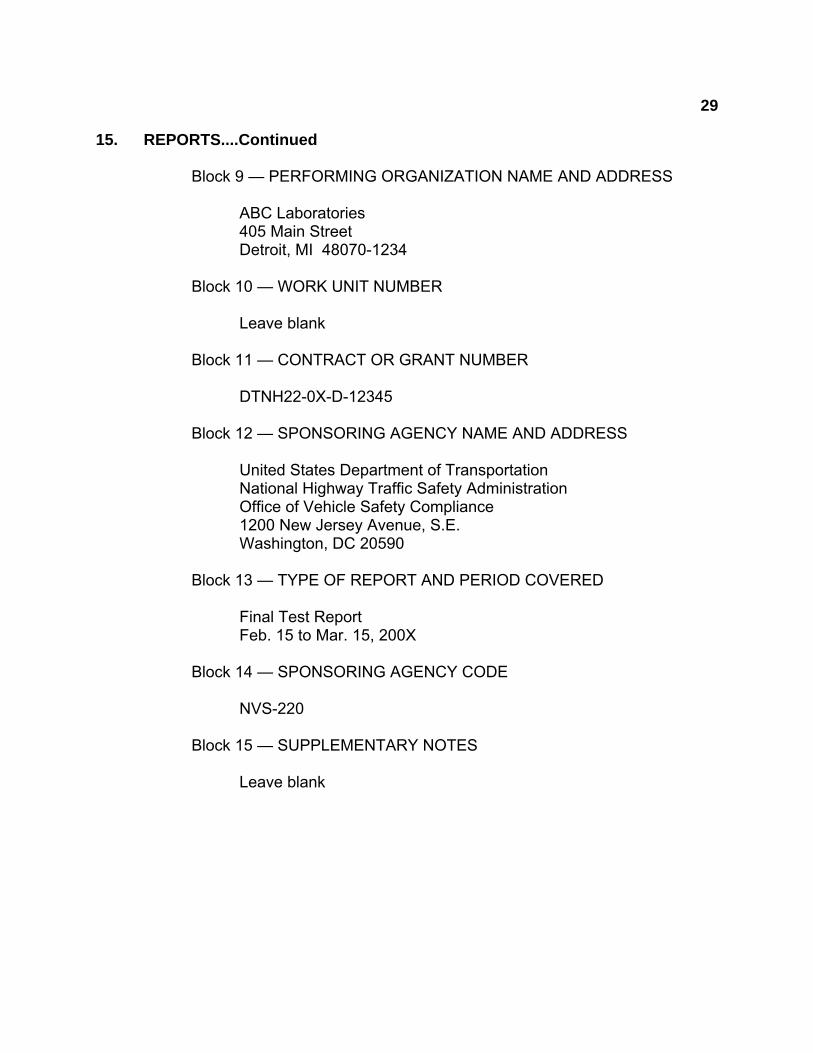
15. REPORTS....Continued
Block 9 — PERFORMING ORGANIZATION NAME AND ADDRESS
ABC Laboratories 405 Main Street Detroit, MI 48070-1234
Block 10 — WORK UNIT NUMBER
Leave blank
Block 11 — CONTRACT OR GRANT NUMBER
DTNH22-0X-D-12345
Block 12 — SPONSORING AGENCY NAME AND ADDRESS
United States Department of Transportation National Highway Traffic Safety Administration Office of Vehicle Safety Compliance 1200 New Jersey Avenue, S.E. Washington, DC 20590
Block 13 — TYPE OF REPORT AND PERIOD COVERED
Final Test Report Feb. 15 to Mar. 15, 200X
Block 14 — SPONSORING AGENCY CODE
NVS-220
Block 15 — SUPPLEMENTARY NOTES
Leave blank
30
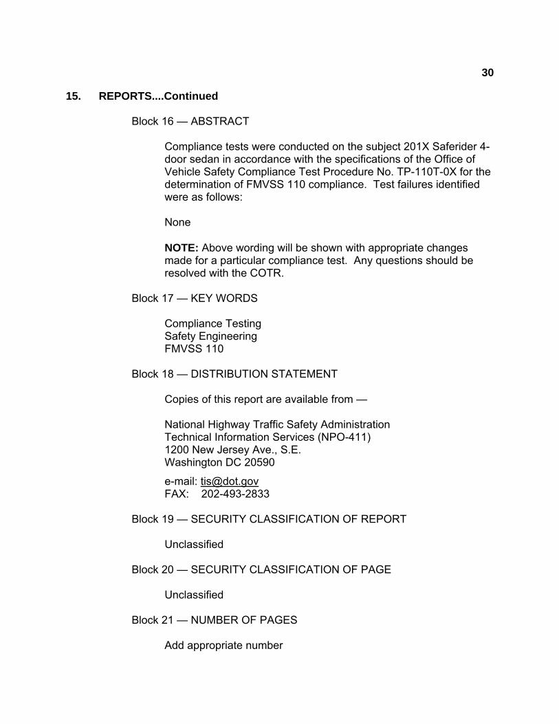
15. REPORTS....Continued
Block 16 — ABSTRACT
Compliance tests were conducted on the subject 201X Saferider 4-door sedan in accordance with the specifications of the Office of Vehicle Safety Compliance Test Procedure No. TP-110T-0X for the determination of FMVSS 110 compliance. Test failures identified were as follows:
None
NOTE: Above wording will be shown with appropriate changes made for a particular compliance test. Any questions should be resolved with the COTR.
Block 17 — KEY WORDS
Compliance Testing Safety Engineering FMVSS 110
Block 18 — DISTRIBUTION STATEMENT
Copies of this report are available from —
National Highway Traffic Safety Administration Technical Information Services (NPO-411) 1200 New Jersey Ave., S.E. Washington DC 20590
e-mail: [email protected] FAX: 202-493-2833
Block 19 — SECURITY CLASSIFICATION OF REPORT
Unclassified
Block 20 — SECURITY CLASSIFICATION OF PAGE
Unclassified
Block 21 — NUMBER OF PAGES
Add appropriate number

31
15. REPORTS....Continued
Block 22 — PRICE
Leave blank 15.3.4 TABLE OF CONTENTS
Final test report Table of Contents will include the following:
Section 1 — Purpose of Compliance Test
Section 2 — Test Procedure and Discussion of Results
Section 3 — Test Data
Section 4 — Test Equipment List and Calibration Information
Section 6 — Other Documentation
Section 7 — Notice of Test Failure (if applicable)
32
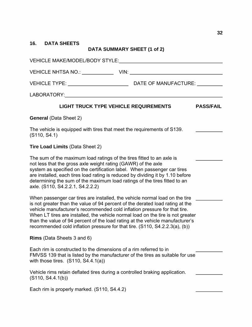
16. DATA SHEETS DATA SUMMARY SHEET (1 of 2) VEHICLE MAKE/MODEL/BODY STYLE: VEHICLE NHTSA NO.: VIN: VEHICLE TYPE: DATE OF MANUFACTURE: LABORATORY:
LIGHT TRUCK TYPE VEHICLE REQUIREMENTS PASS/FAIL General (Data Sheet 2) The vehicle is equipped with tires that meet the requirements of S139. (S110, S4.1) Tire Load Limits (Data Sheet 2) The sum of the maximum load ratings of the tires fitted to an axle is not less that the gross axle weight rating (GAWR) of the axle system as specified on the certification label. When passenger car tires are installed, each tires load rating is reduced by dividing it by 1.10 before determining the sum of the maximum load ratings of the tires fitted to an axle. (S110, S4.2.2.1, S4.2.2.2) When passenger car tires are installed, the vehicle normal load on the tire is not greater than the value of 94 percent of the derated load rating at the vehicle manufacturer’s recommended cold inflation pressure for that tire. When LT tires are installed, the vehicle normal load on the tire is not greater than the value of 94 percent of the load rating at the vehicle manufacturer’s recommended cold inflation pressure for that tire. (S110, S4.2.2.3(a), (b)) Rims (Data Sheets 3 and 6) Each rim is constructed to the dimensions of a rim referred to in FMVSS 139 that is listed by the manufacturer of the tires as suitable for use with those tires. (S110, S4.4.1(a)) Vehicle rims retain deflated tires during a controlled braking application. (S110, S4.4.1(b)) Each rim is properly marked. (S110, S4.4.2)
33
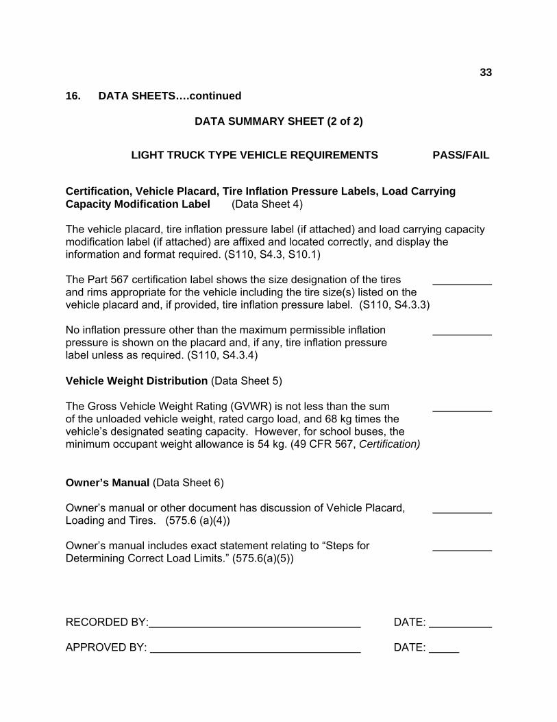
16. DATA SHEETS….continued DATA SUMMARY SHEET (2 of 2) LIGHT TRUCK TYPE VEHICLE REQUIREMENTS PASS/FAIL Certification, Vehicle Placard, Tire Inflation Pressure Labels, Load Carrying Capacity Modification Label (Data Sheet 4) The vehicle placard, tire inflation pressure label (if attached) and load carrying capacity modification label (if attached) are affixed and located correctly, and display the information and format required. (S110, S4.3, S10.1) The Part 567 certification label shows the size designation of the tires and rims appropriate for the vehicle including the tire size(s) listed on the vehicle placard and, if provided, tire inflation pressure label. (S110, S4.3.3) No inflation pressure other than the maximum permissible inflation pressure is shown on the placard and, if any, tire inflation pressure label unless as required. (S110, S4.3.4) Vehicle Weight Distribution (Data Sheet 5) The Gross Vehicle Weight Rating (GVWR) is not less than the sum of the unloaded vehicle weight, rated cargo load, and 68 kg times the vehicle’s designated seating capacity. However, for school buses, the minimum occupant weight allowance is 54 kg. (49 CFR 567, Certification) Owner’s Manual (Data Sheet 6) Owner’s manual or other document has discussion of Vehicle Placard, Loading and Tires. (575.6 (a)(4)) Owner’s manual includes exact statement relating to “Steps for Determining Correct Load Limits.” (575.6(a)(5)) RECORDED BY: DATE: APPROVED BY: DATE:
34
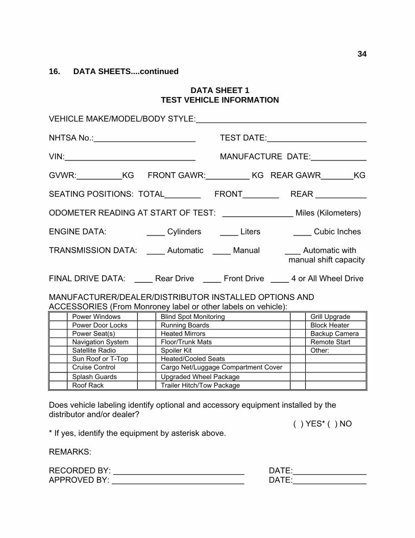
16. DATA SHEETS....continued DATA SHEET 1 TEST VEHICLE INFORMATION VEHICLE MAKE/MODEL/BODY STYLE: NHTSA No.: TEST DATE: VIN: MANUFACTURE DATE: GVWR: KG FRONT GAWR: KG REAR GAWR KG SEATING POSITIONS: TOTAL FRONT REAR ODOMETER READING AT START OF TEST: Miles (Kilometers) ENGINE DATA: Cylinders Liters Cubic Inches TRANSMISSION DATA: Automatic Manual Automatic with manual shift capacity FINAL DRIVE DATA: Rear Drive Front Drive 4 or All Wheel Drive MANUFACTURER/DEALER/DISTRIBUTOR INSTALLED OPTIONS AND ACCESSORIES (From Monroney label or other labels on vehicle):
Power Windows Blind Spot Monitoring Grill Upgrade Power Door Locks Running Boards Block Heater Power Seat(s) Heated Mirrors Backup Camera Navigation System Floor/Trunk Mats Remote Start Satellite Radio Spoiler Kit Other: Sun Roof or T-Top Heated/Cooled Seats Cruise Control Cargo Net/Luggage Compartment Cover
Splash Guards Upgraded Wheel Package Roof Rack Trailer Hitch/Tow Package
Does vehicle labeling identify optional and accessory equipment installed by the distributor and/or dealer? ( ) YES* ( ) NO * If yes, identify the equipment by asterisk above. REMARKS: RECORDED BY: DATE: APPROVED BY: DATE:
35
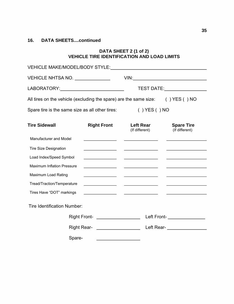
16. DATA SHEETS....continued DATA SHEET 2 (1 of 2) VEHICLE TIRE IDENTIFICATION AND LOAD LIMITS VEHICLE MAKE/MODEL/BODY STYLE: VEHICLE NHTSA NO. VIN: LABORATORY: TEST DATE: All tires on the vehicle (excluding the spare) are the same size: ( ) YES ( ) NO Spare tire is the same size as all other tires: ( ) YES ( ) NO Tire Sidewall Right Front Left Rear Spare Tire
(If different) (If different)
Manufacturer and Model Tire Size Designation Load Index/Speed Symbol Maximum Inflation Pressure Maximum Load Rating Tread/Traction/Temperature Tires Have “DOT” markings Tire Identification Number: Right Front- Left Front- Right Rear- Left Rear- Spare-

36
16. DATA SHEETS....continued
DATA SHEET 2 (2 of 2) VEHICLE TIRE IDENTIFICATION AND LOAD LIMITS
MOUNTED TIRE VS. AXLE RATING COMPARISON (at sidewall maximum inflation pressure)
FRONT AXLE
REAR AXLE A. GAWR (KG) from certification label
B. Tire Maximum Load Rating from tire sidewall (KG)
C. Reduced Tire Load Rating if applicable (KG)*
D. (Number of tires on axle) x (tire load rating, de-rated if
appropriate)
Is “D” equal to or greater than “A” ? (Yes/No)
* If a passenger car tire is installed on a multipurpose passenger vehicle (MPV), truck or bus, the tire’s load rating is reduced by dividing by 1.10. DATA INDICATES COMPLIANCE: PASS/FAIL REMARKS: RECORDED BY: DATE: APPROVED BY: DATE:
37
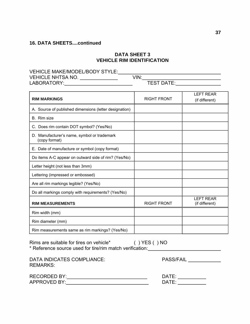
16. DATA SHEETS....continued DATA SHEET 3 VEHICLE RIM IDENTIFICATION VEHICLE MAKE/MODEL/BODY STYLE: VEHICLE NHTSA NO. VIN: LABORATORY: TEST DATE:
RIM MARKINGS
RIGHT FRONT
LEFT REAR
(if different) A. Source of published dimensions (letter designation)
B. Rim size
C. Does rim contain DOT symbol? (Yes/No)
D. Manufacturer’s name, symbol or trademark (copy format)
E. Date of manufacture or symbol (copy format)
Do items A-C appear on outward side of rim? (Yes/No)
Letter height (not less than 3mm)
Lettering (impressed or embossed)
Are all rim markings legible? (Yes/No)
Do all markings comply with requirements? (Yes/No)
RIM MEASUREMENTS
RIGHT FRONT
LEFT REAR (if different)
Rim width (mm)
Rim diameter (mm)
Rim measurements same as rim markings? (Yes/No)
Rims are suitable for tires on vehicle* ( ) YES ( ) NO * Reference source used for tire/rim match verification: DATA INDICATES COMPLIANCE: PASS/FAIL REMARKS: RECORDED BY: DATE: APPROVED BY: DATE:
38
16. DATA SHEETS....continued
DATA SHEET 4 (1 of 5) VEHICLE PLACARD, TIRE INFLATION PRESSURE LABEL, AND OTHER LABELS
VEHICLE MAKE/MODEL/BODY STYLE: VEHICLE NHTSA NO. VIN: LABORATORY: TEST DATE: Identification of Vehicle Labeling
(Yes/No) Location PASS/FAIL
1. Monroney Label Not Applicable (if attached)
2. Certification Label* Not Applicable
3. Alterer’s Label Not Applicable (if attached) 4. Vehicle Placard* 5. Tire Inflation Pressure Label* (if attached)
6. Load Carrying Capacity Modification Label* _______ ____________________ __________ (if attached)
7. Dealer/Distributor Not Applicable Optional Equipment
Added Label (if attached) * Labels are to be located as specified in section 13.4 of this test procedure.
39
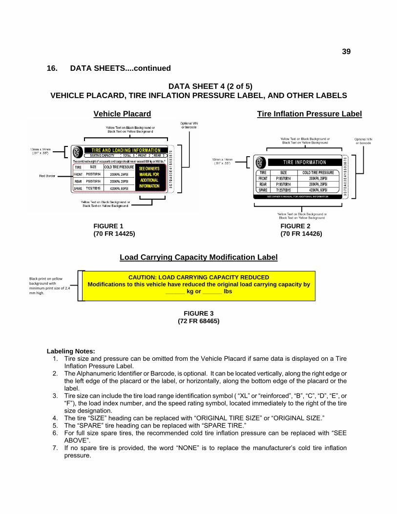
16. DATA SHEETS....continued DATA SHEET 4 (2 of 5) VEHICLE PLACARD, TIRE INFLATION PRESSURE LABEL, AND OTHER LABELS
Vehicle Placard Tire Inflation Pressure Label
FIGURE 1 FIGURE 2 (70 FR 14425) (70 FR 14426)
Load Carrying Capacity Modification Label
FIGURE 3 (72 FR 68465)
Labeling Notes: 1. Tire size and pressure can be omitted from the Vehicle Placard if same data is displayed on a Tire
Inflation Pressure Label. 2. The Alphanumeric Identifier or Barcode, is optional. It can be located vertically, along the right edge or
the left edge of the placard or the label, or horizontally, along the bottom edge of the placard or the label.
3. Tire size can include the tire load range identification symbol ( “XL” or “reinforced”, “B”, “C”, “D”, “E”, or “F”), the load index number, and the speed rating symbol, located immediately to the right of the tire size designation.
4. The tire “SIZE” heading can be replaced with “ORIGINAL TIRE SIZE” or “ORIGINAL SIZE.” 5. The “SPARE” tire heading can be replaced with “SPARE TIRE.” 6. For full size spare tires, the recommended cold tire inflation pressure can be replaced with “SEE
ABOVE”. 7. If no spare tire is provided, the word “NONE” is to replace the manufacturer’s cold tire inflation
pressure.
CAUTION: LOAD CARRYING CAPACITY REDUCED Modifications to this vehicle have reduced the original load carrying capacity by
______ kg or ______ lbs
Black print on yellow background with minimum print size of 2.4 mm high.

40
16. DATA SHEETS....continued
DATA SHEET 4 (3 of 5) VEHICLE PLACARD, TIRE INFLATION PRESSURE LABEL, AND OTHER LABELS
Vehicle Placard has the exact color and format as specified in the above Figure 1 and
text is in English language. ( ) YES ( ) NO If no, explain
Tire Inflation Pressure Label, if attached, has the exact color and format as specified in the above Figure 2 and text is in English language. ( ) YES ( ) NO
If no, explain
Load Carrying Capacity Modification Label, if attached, has the exact color and format as specified in the above Figure 3 and text is in the English language. Verify the label is within 25 mm of vehicle placard and has minimum print size of 2.4 mm high. ( ) YES ( ) NO
If no, explain _______________________________________________
Vehicle Placard, Tire Inflation Pressure Label (if attached), and Load Carrying Capacity Modification Label (if attached) are permanently affixed. ( ) YES ( ) NO
Vehicle Placard information:
Combined weight of occupants and cargo kg ( lbs)
Seating Capacity: Total ; Front ; Rear ;
Is the number of belted seating positions the same as the labeled seating capacity? ( ) YES ( ) NO
If no, explain Is the tire size and pressure provided? ( ) YES ( ) NO If no, is the tire size and pressure provided on a Tire Inflation Pressure Label? ( ) YES ( ) NO
41
16. DATA SHEETS....continued
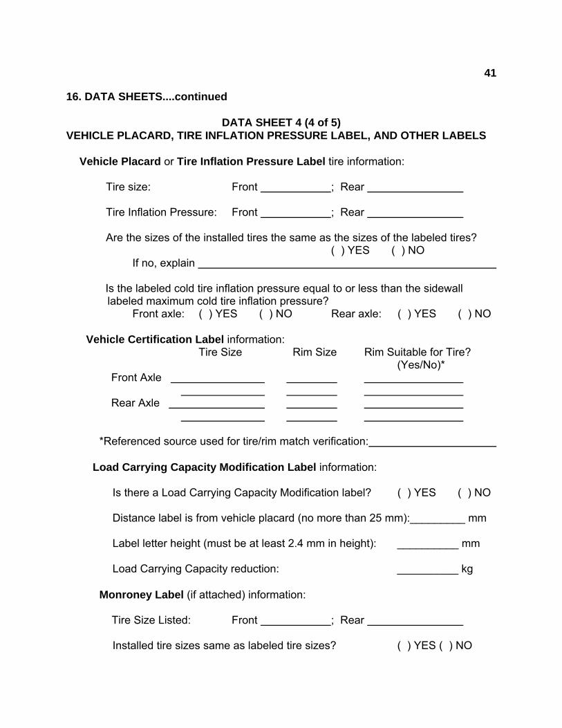
DATA SHEET 4 (4 of 5) VEHICLE PLACARD, TIRE INFLATION PRESSURE LABEL, AND OTHER LABELS
Vehicle Placard or Tire Inflation Pressure Label tire information:
Tire size: Front ; Rear
Tire Inflation Pressure: Front ; Rear
Are the sizes of the installed tires the same as the sizes of the labeled tires? ( ) YES ( ) NO
If no, explain Is the labeled cold tire inflation pressure equal to or less than the sidewall
labeled maximum cold tire inflation pressure? Front axle: ( ) YES ( ) NO Rear axle: ( ) YES ( ) NO
Vehicle Certification Label information: Tire Size Rim Size Rim Suitable for Tire? (Yes/No)*
Front Axle
Rear Axle
*Referenced source used for tire/rim match verification:
Load Carrying Capacity Modification Label information:
Is there a Load Carrying Capacity Modification label? ( ) YES ( ) NO
Distance label is from vehicle placard (no more than 25 mm):_________ mm
Label letter height (must be at least 2.4 mm in height): __________ mm
Load Carrying Capacity reduction: __________ kg Monroney Label (if attached) information:
Tire Size Listed: Front ; Rear
Installed tire sizes same as labeled tire sizes? ( ) YES ( ) NO
42
16. DATA SHEETS....continued
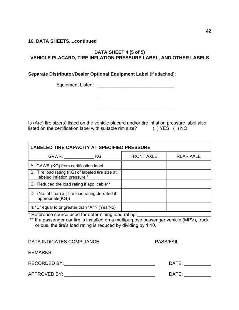
DATA SHEET 4 (5 of 5) VEHICLE PLACARD, TIRE INFLATION PRESSURE LABEL, AND OTHER LABELS
Separate Distributor/Dealer Optional Equipment Label (if attached): Equipment Listed: _____________________________ _____________________________ _____________________________
Is (Are) tire size(s) listed on the vehicle placard and/or tire inflation pressure label also listed on the certification label with suitable rim size? ( ) YES ( ) NO LABELED TIRE CAPACITY AT SPECIFIED PRESSURE
GVWR: KG FRONT AXLE
REAR AXLE A. GAWR (KG) from certification label
B. Tire load rating (KG) of labeled tire size at labeled inflation pressure *
C. Reduced tire load rating if applicable**
D. (No. of tires) x (Tire load rating de-rated if appropriate(KG))
Is “D” equal to or greater than “A” ? (Yes/No)
* Reference source used for determining load rating: ** If a passenger car tire is installed on a multipurpose passenger vehicle (MPV), truck or bus, the tire’s load rating is reduced by dividing by 1.10.
DATA INDICATES COMPLIANCE: PASS/FAIL REMARKS: RECORDED BY: DATE: APPROVED BY: DATE:
43
16. DATA SHEETS....continued
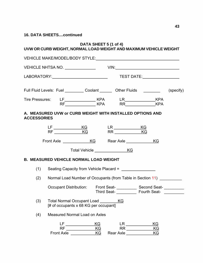
DATA SHEET 5 (1 of 4) UVW OR CURB WEIGHT, NORMAL LOAD WEIGHT AND MAXIMUM VEHICLE WEIGHT VEHICLE MAKE/MODEL/BODY STYLE: VEHICLE NHTSA NO. VIN: LABORATORY: TEST DATE: Full Fluid Levels: Fuel Coolant Other Fluids (specify) Tire Pressures: LF KPA LR KPA
RF KPA RR KPA A. MEASURED UVW or CURB WEIGHT WITH INSTALLED OPTIONS AND ACCESSORIES
LF KG LR KG RF KG RR KG
Front Axle KG Rear Axle KG
Total Vehicle KG B. MEASURED VEHICLE NORMAL LOAD WEIGHT
(1) Seating Capacity from Vehicle Placard =
(2) Normal Load Number of Occupants (from Table in Section 11) __________
Occupant Distribution: Front Seat- _________ Second Seat- _________ Third Seat- _________ Fourth Seat- _________
(3) Total Normal Occupant Load KG [# of occupants x 68 KG per occupant]
(4) Measured Normal Load on Axles
LF KG LR KG RF KG RR KG Front Axle KG Rear Axle KG
44
16. DATA SHEETS....continued
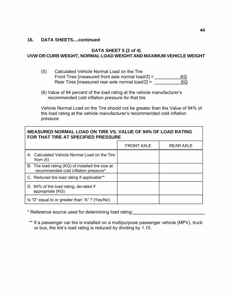
DATA SHEET 5 (2 of 4) UVW OR CURB WEIGHT, NORMAL LOAD WEIGHT AND MAXIMUM VEHICLE WEIGHT
(5) Calculated Vehicle Normal Load on the Tire
Front Tires [measured front axle normal load/2] = KG Rear Tires [measured rear axle normal load/2] = KG
(6) Value of 94 percent of the load rating at the vehicle manufacturer’s
recommended cold inflation pressure for that tire Vehicle Normal Load on the Tire should not be greater than the Value of 94% of the load rating at the vehicle manufacturer’s recommended cold inflation pressure
MEASURED NORMAL LOAD ON TIRE VS. VALUE OF 94% OF LOAD RATING FOR THAT TIRE AT SPECIFIED PRESSURE
FRONT AXLE REAR AXLE A. Calculated Vehicle Normal Load on the Tire from (5)
B. Tire load rating (KG) of installed tire size at recommended cold inflation pressure*
C. Reduced tire load rating if applicable** D. 94% of tire load rating, de-rated if
appropriate (KG)
Is “D” equal to or greater than “A” ? (Yes/No)
* Reference source used for determining load rating: ** If a passenger car tire is installed on a multipurpose passenger vehicle (MPV), truck or bus, the tire’s load rating is reduced by dividing by 1.10.
45
16. DATA SHEETS....continued
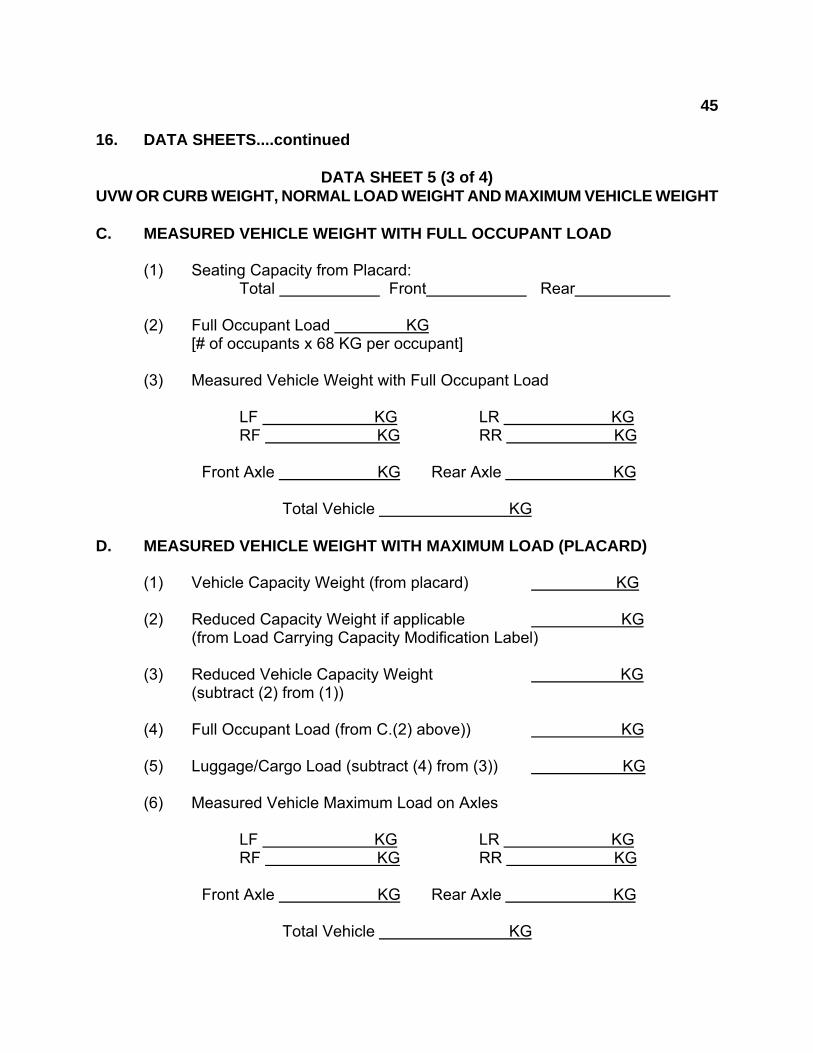
DATA SHEET 5 (3 of 4) UVW OR CURB WEIGHT, NORMAL LOAD WEIGHT AND MAXIMUM VEHICLE WEIGHT C. MEASURED VEHICLE WEIGHT WITH FULL OCCUPANT LOAD
(1) Seating Capacity from Placard: Total Front Rear
(2) Full Occupant Load KG
[# of occupants x 68 KG per occupant] (3) Measured Vehicle Weight with Full Occupant Load
LF KG LR KG RF KG RR KG
Front Axle KG Rear Axle KG
Total Vehicle KG D. MEASURED VEHICLE WEIGHT WITH MAXIMUM LOAD (PLACARD)
(1) Vehicle Capacity Weight (from placard) KG
(2) Reduced Capacity Weight if applicable KG (from Load Carrying Capacity Modification Label) (3) Reduced Vehicle Capacity Weight KG
(subtract (2) from (1)) (4) Full Occupant Load (from C.(2) above)) KG
(5) Luggage/Cargo Load (subtract (4) from (3)) KG
(6) Measured Vehicle Maximum Load on Axles
LF KG LR KG RF KG RR KG
Front Axle KG Rear Axle KG
Total Vehicle KG

46
16. DATA SHEETS....continued
DATA SHEET 5 (4 of 4) UVW OR CURB WEIGHT, NORMAL LOAD WEIGHT AND MAXIMUM VEHICLE WEIGHT
VEHICLE WEIGHT DISTRIBUTION TABLE
ITEM
Tire or Vehicle Rating*
(KG)
Unloaded Vehicle
Weight or Curb Weight (KG)
Vehicle Weight with Full Occupant Load
(KG)
Vehicle Maximum Weight with Occupants
and Cargo (KG)
Measured Overload Measured Overload
Measured Overload
Left Front Tire
Right Front Tire
Front Axle (GAWR)
Left Rear Tire
Right Rear Tire
Rear Axle (GAWR)
Total Vehicle (GVWR)
* Vehicle and axle weight ratings (GVWR & GAWR) are located on the vehicle certification label. Vehicle tire load ratings are based upon the inflation pressure specified on the Vehicle Placard or Tire Inflation Pressure Label for each respective axle, as determined from the appropriate Tire and Rim reference manual. If a passenger car tire is installed on a multipurpose passenger vehicle (MPV), truck or bus, the tire’s load rating is reduced by dividing by 1.10.
DATA INDICATES COMPLIANCE: PASS/FAIL REMARKS: RECORDED BY: DATE: APPROVED BY: DATE:
47
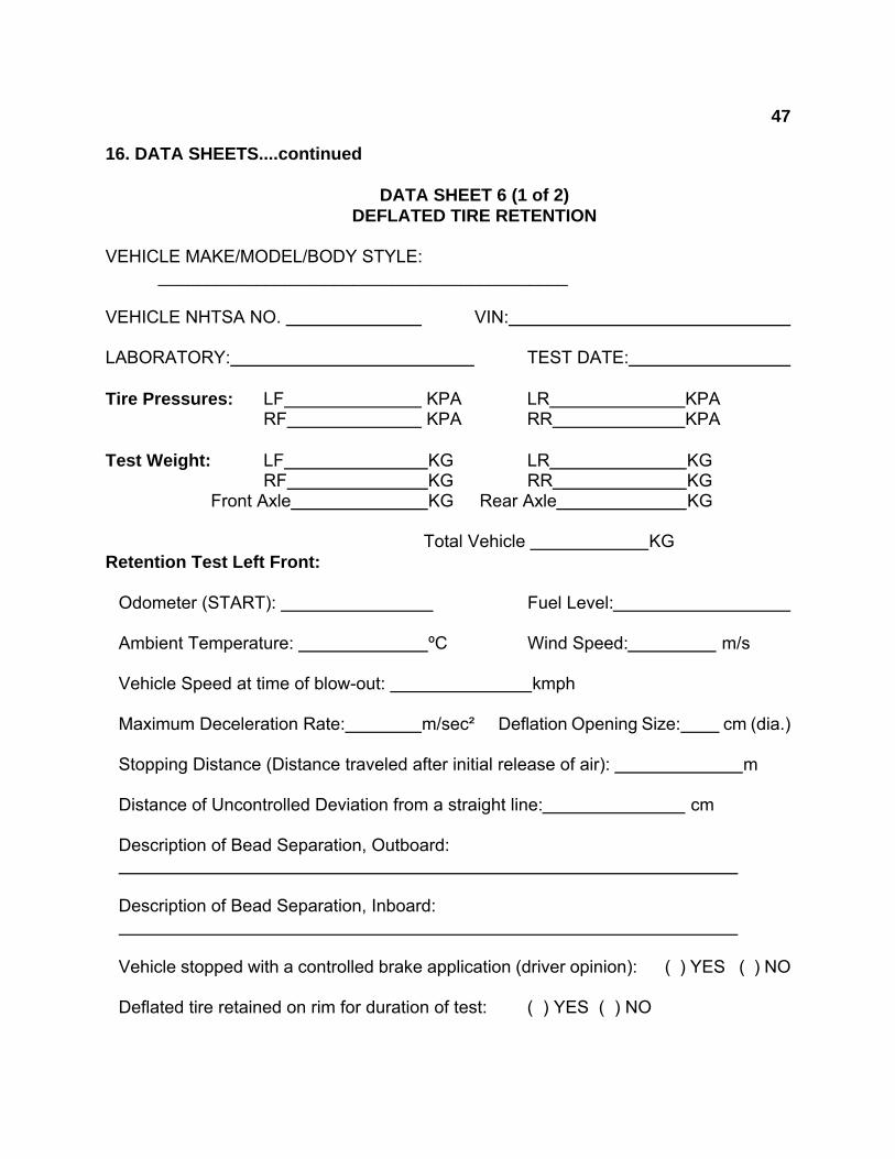
16. DATA SHEETS....continued DATA SHEET 6 (1 of 2) DEFLATED TIRE RETENTION VEHICLE MAKE/MODEL/BODY STYLE: __________________________________________ VEHICLE NHTSA NO. VIN: LABORATORY: TEST DATE: Tire Pressures: LF KPA LR KPA
RF KPA RR KPA Test Weight: LF KG LR KG
RF KG RR KG Front Axle KG Rear Axle KG Total Vehicle KG Retention Test Left Front:
Odometer (START): Fuel Level: Ambient Temperature: ºC Wind Speed: m/s Vehicle Speed at time of blow-out: kmph Maximum Deceleration Rate: m/sec² Deflation Opening Size: cm (dia.) Stopping Distance (Distance traveled after initial release of air): m Distance of Uncontrolled Deviation from a straight line: cm Description of Bead Separation, Outboard: Description of Bead Separation, Inboard: Vehicle stopped with a controlled brake application (driver opinion): ( ) YES ( ) NO Deflated tire retained on rim for duration of test: ( ) YES ( ) NO

48
16. DATA SHEETS....continued DATA SHEET 6 (2 of 2) DEFLATED TIRE RETENTION Retention Test Right Rear:
Odometer (START): Fuel Level: Ambient Temperature: ºC Wind Speed: m/s Vehicle Speed at time of blow-out: kmph Maximum Deceleration Rate: m/sec² Deflation Opening Size: cm (dia.) Stopping Distance (Distance traveled after initial release of air): m Distance of Uncontrolled Deviation from a straight line: cm Description of Bead Separation, Outboard: Description of Bead Separation, Inboard: Vehicle stopped with a controlled brake application (driver opinion): ( ) YES ( ) NO Deflated tire retained on rim for duration of test: ( ) YES ( ) NO
PASS/FAIL
DATA INDICATES COMPLIANCE: LEFT FRONT RIGHT REAR REMARKS: RECORDED BY: DATE: APPROVED BY: DATE:
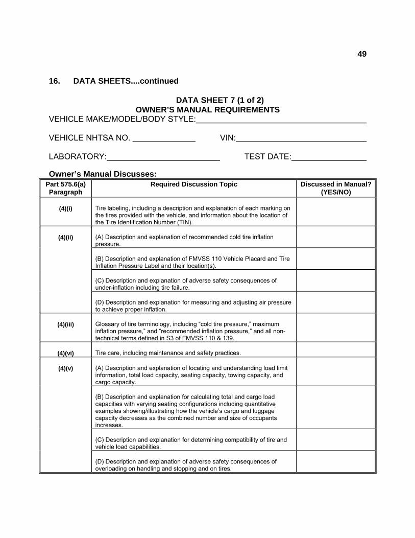
49
16. DATA SHEETS....continued DATA SHEET 7 (1 of 2)
OWNER’S MANUAL REQUIREMENTS VEHICLE MAKE/MODEL/BODY STYLE: VEHICLE NHTSA NO. VIN: LABORATORY: TEST DATE: Owner’s Manual Discusses:
Part 575.6(a) Paragraph
Required Discussion Topic Discussed in Manual?(YES/NO)
(4)(i)
Tire labeling, including a description and explanation of each marking on the tires provided with the vehicle, and information about the location of the Tire Identification Number (TIN).
(4)(ii)
(A) Description and explanation of recommended cold tire inflation pressure.
(B) Description and explanation of FMVSS 110 Vehicle Placard and Tire Inflation Pressure Label and their location(s).
(C) Description and explanation of adverse safety consequences of under-inflation including tire failure.
(D) Description and explanation for measuring and adjusting air pressure to achieve proper inflation.
(4)(iii)
Glossary of tire terminology, including “cold tire pressure,” maximum inflation pressure,” and “recommended inflation pressure,” and all non-technical terms defined in S3 of FMVSS 110 & 139.
(4)(vi)
Tire care, including maintenance and safety practices.
(4)(v)
(A) Description and explanation of locating and understanding load limit information, total load capacity, seating capacity, towing capacity, and cargo capacity.
(B) Description and explanation for calculating total and cargo load capacities with varying seating configurations including quantitative examples showing/illustrating how the vehicle’s cargo and luggage capacity decreases as the combined number and size of occupants increases.
(C) Description and explanation for determining compatibility of tire and vehicle load capabilities.
(D) Description and explanation of adverse safety consequences of overloading on handling and stopping and on tires.
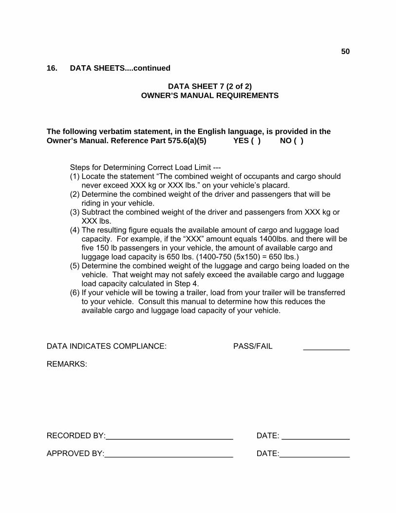
50
16. DATA SHEETS....continued DATA SHEET 7 (2 of 2) OWNER’S MANUAL REQUIREMENTS The following verbatim statement, in the English language, is provided in the Owner’s Manual. Reference Part 575.6(a)(5) YES ( ) NO ( ) Steps for Determining Correct Load Limit ---
(1) Locate the statement “The combined weight of occupants and cargo should never exceed XXX kg or XXX lbs.” on your vehicle’s placard.
(2) Determine the combined weight of the driver and passengers that will be riding in your vehicle.
(3) Subtract the combined weight of the driver and passengers from XXX kg or XXX lbs.
(4) The resulting figure equals the available amount of cargo and luggage load capacity. For example, if the “XXX” amount equals 1400lbs. and there will be five 150 lb passengers in your vehicle, the amount of available cargo and luggage load capacity is 650 lbs. (1400-750 (5x150) = 650 lbs.)
(5) Determine the combined weight of the luggage and cargo being loaded on the vehicle. That weight may not safely exceed the available cargo and luggage load capacity calculated in Step 4.
(6) If your vehicle will be towing a trailer, load from your trailer will be transferred to your vehicle. Consult this manual to determine how this reduces the available cargo and luggage load capacity of your vehicle.
DATA INDICATES COMPLIANCE: PASS/FAIL REMARKS: RECORDED BY: DATE: APPROVED BY: DATE:

51
17. FORMS LABORATORY NOTICE OF TEST FAILURE TO OVSC FMVSS NO.: 110 TEST DATE: LABORATORY: CONTRACT NO.: DELV. ORDER NO.: LABORATORY PROJECT ENGINEER'S NAME: TEST SPECIMEN DESCRIPTION:
VEHICLE NHTSA NO.: VIN: MFR: TEST FAILURE DESCRIPTION: FMVSS REQUIREMENT, PARAGRAPH S : NOTIFICATION TO NHTSA (COTR): DATE: BY: REMARKS:
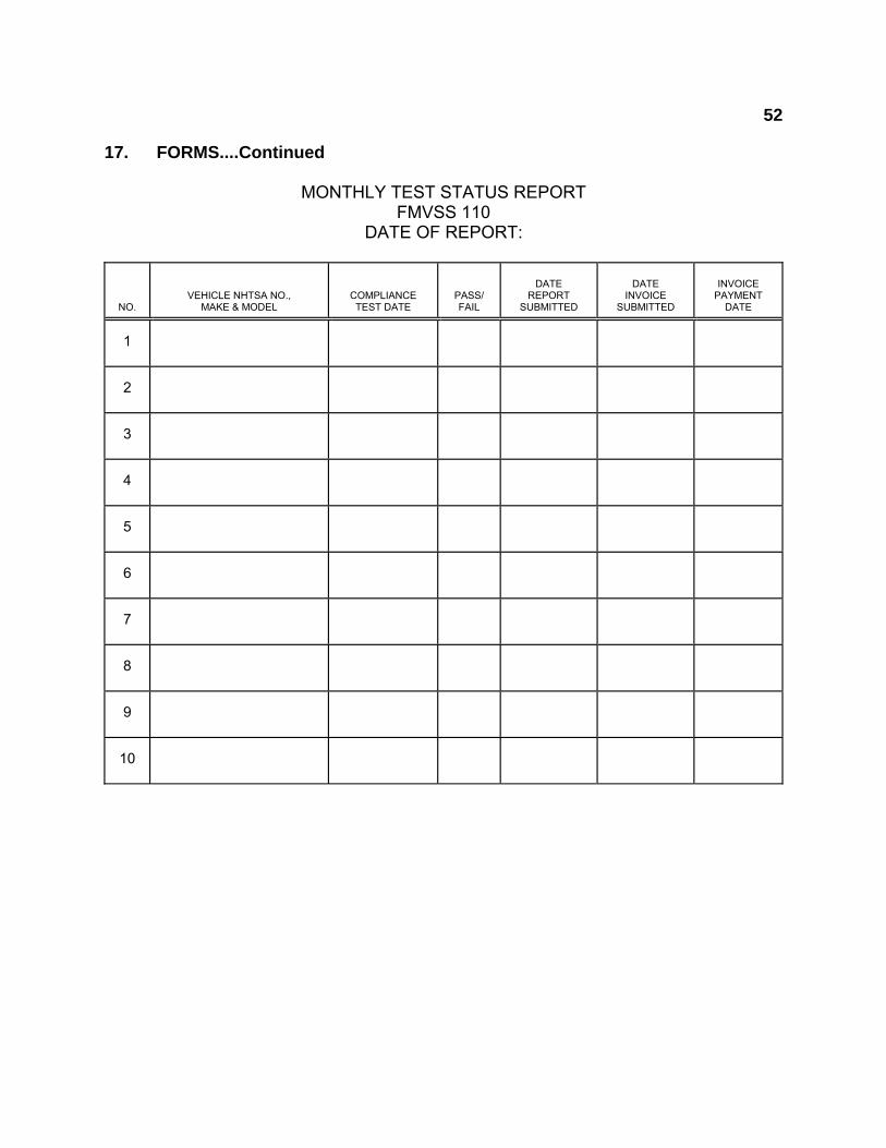
52
17. FORMS....Continued MONTHLY TEST STATUS REPORT FMVSS 110 DATE OF REPORT:
NO.
VEHICLE NHTSA NO., MAKE & MODEL
COMPLIANCE TEST DATE
PASS/ FAIL
DATE
REPORT SUBMITTED
DATE
INVOICE SUBMITTED
INVOICE
PAYMENT DATE
1
2
3
4
5
6
7
8
9
10
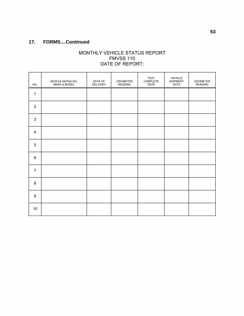
53
17. FORMS....Continued MONTHLY VEHICLE STATUS REPORT FMVSS 110 DATE OF REPORT:
NO.
VEHICLE NHTSA NO., MAKE & MODEL
DATE OF DELIVERY
ODOMETER READING
TEST
COMPLETE DATE
VEHICLE
SHIPMENT DATE
ODOMETER READING
1
2
3
4
5
6
7
8
9
10