Embed Size (px)
Citation preview

U.S. Departmentof Transportation
Federal Aviation
Administration
APRIL 3, 2014
AERONAUTICAL
INFORMATION
MANUAL
Change 3June 25, 2015
DO NOT DESTROYBASIC DATED


AIM6/25/15
Explanation of Changes E of Chg−1
Aeronautical Information ManualExplanation of Changes
Effective: June 25, 2015
a. 1−1−7. Distance Measuring Equipment(DME)
1−1−16. Inertial Reference Unit (IRU),Inertial Navigation System (INS), and AttitudeHeading Reference System (AHRS)
This changes relocates the information containedwithin subparagraph d from paragraph 1−1−7 toparagraph 1−1−16, as the latter was a moreappropriate destination for the information containedtherein.
b. 1−1−11. Microwave Landing System (MLS)5−1−9. International Flight Plan (FAA
Form 7233−4)− IFR Flights (For Domestic orInternational Flights)
Appendix 3. Abbreviations/AcronymsPilot/Controller Glossary (various places)
This change removes all references to MicrowaveLanding System (MLS).
c. 2−1−2. Visual Glideslope Indicators
This change adds verbiage to describe how theobstacle clearance area for a Visual Approach SlopeIndicator (VASI) and/or Precision Approach PathIndicator (PAPI) may be changed. This change alsoinstructs pilots to check notices to airmen (NOTAM)for information on VASI and/or PAPI clearance areachanges.
d. 4−1−16. Safety Alert
In 2013, changes were incorporated into FAA Order7110.65, Paragraph 2−1−6, Safety Alert, thatremoved the requirement to issue Decision Altitude(DA), Minimum Descent Altitude (MDA), orDecision Height (DH) in the event an aircraft exceedsthe safety limits for a particular approach. This
change reflects those requirements and providessymmetry amongst all guidance/procedures.
e. 4−3−3. Traffic Patterns
This change updates guidance regarding trafficpattern charting to bring forth more clarity.
f. 5−2−8. Instrument Departure Procedures(DP) − Obstacle Departure Procedures (ODP) andStandard Instrument Departures (SID)
This change provides guidance regarding diversevector areas and their use in greater detail.
g. 5−4−8. Special Instrument Approach Proced-ures
This change includes information on NOTAMs forSpecial Instrument Approach Procedures.
h. 5−4−15. Simultaneous Parallel ILS/RNAV/GLS Approaches (Independent)
This change reflects updated charting revisions.FIG 5−4−20 is also updated to improve clarity of thedepicted concepts.
i. 5−4−17. Simultaneous Converging Instru-ment Approaches
This change is updated to reflect the use of letter “V”in the approach title to indicate a simultaneousconverging approach.
j. Pilot/Controller Glossary
Terms have been added, deleted, or modified withinthis glossary. Please refer to page PCG−1 for moredetails.
k. Entire publication.
Editorial/format changes were made where neces-sary. Revision bars were not used when changes areinsignificant in nature.

AIM6/25/15
Page Control Chart
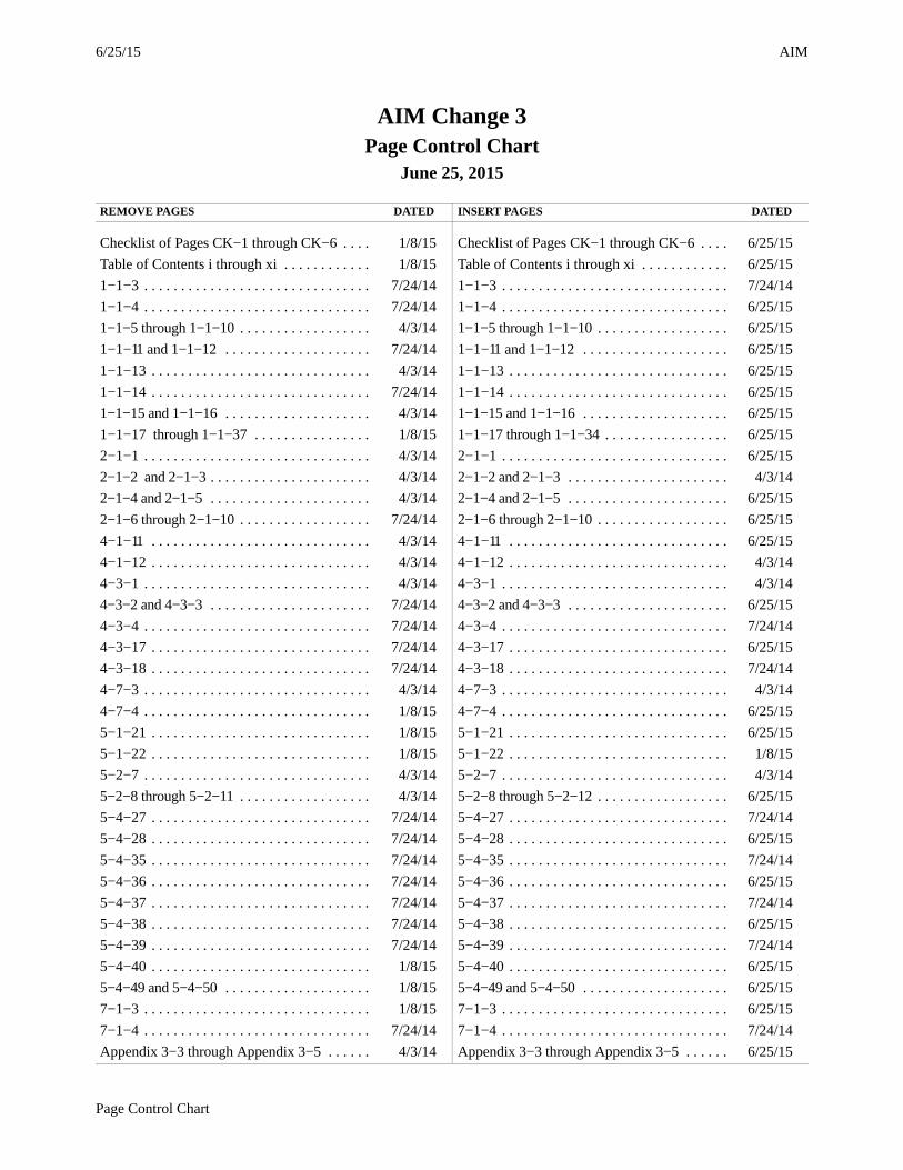
AIM Change 3Page Control Chart
June 25, 2015
REMOVE PAGES DATED INSERT PAGES DATED
Checklist of Pages CK−1 through CK−6 . . . . 1/8/15 Checklist of Pages CK−1 through CK−6 . . . . 6/25/15
Table of Contents i through xi . . . . . . . . . . . . 1/8/15 Table of Contents i through xi . . . . . . . . . . . . 6/25/15
1−1−3 . . . . . . . . . . . . . . . . . . . . . . . . . . . . . . . 7/24/14 1−1−3 . . . . . . . . . . . . . . . . . . . . . . . . . . . . . . . 7/24/14
1−1−4 . . . . . . . . . . . . . . . . . . . . . . . . . . . . . . . 7/24/14 1−1−4 . . . . . . . . . . . . . . . . . . . . . . . . . . . . . . . 6/25/15
1−1−5 through 1−1−10 . . . . . . . . . . . . . . . . . . 4/3/14 1−1−5 through 1−1−10 . . . . . . . . . . . . . . . . . . 6/25/15
1−1−11 and 1−1−12 . . . . . . . . . . . . . . . . . . . . 7/24/14 1−1−11 and 1−1−12 . . . . . . . . . . . . . . . . . . . . 6/25/15
1−1−13 . . . . . . . . . . . . . . . . . . . . . . . . . . . . . . 4/3/14 1−1−13 . . . . . . . . . . . . . . . . . . . . . . . . . . . . . . 6/25/15
1−1−14 . . . . . . . . . . . . . . . . . . . . . . . . . . . . . . 7/24/14 1−1−14 . . . . . . . . . . . . . . . . . . . . . . . . . . . . . . 6/25/15
1−1−15 and 1−1−16 . . . . . . . . . . . . . . . . . . . . 4/3/14 1−1−15 and 1−1−16 . . . . . . . . . . . . . . . . . . . . 6/25/15
1−1−17 through 1−1−37 . . . . . . . . . . . . . . . . 1/8/15 1−1−17 through 1−1−34 . . . . . . . . . . . . . . . . . 6/25/15
2−1−1 . . . . . . . . . . . . . . . . . . . . . . . . . . . . . . . 4/3/14 2−1−1 . . . . . . . . . . . . . . . . . . . . . . . . . . . . . . . 6/25/15
2−1−2 and 2−1−3 . . . . . . . . . . . . . . . . . . . . . . 4/3/14 2−1−2 and 2−1−3 . . . . . . . . . . . . . . . . . . . . . . 4/3/14
2−1−4 and 2−1−5 . . . . . . . . . . . . . . . . . . . . . . 4/3/14 2−1−4 and 2−1−5 . . . . . . . . . . . . . . . . . . . . . . 6/25/15
2−1−6 through 2−1−10 . . . . . . . . . . . . . . . . . . 7/24/14 2−1−6 through 2−1−10 . . . . . . . . . . . . . . . . . . 6/25/15
4−1−11 . . . . . . . . . . . . . . . . . . . . . . . . . . . . . . 4/3/14 4−1−11 . . . . . . . . . . . . . . . . . . . . . . . . . . . . . . 6/25/15
4−1−12 . . . . . . . . . . . . . . . . . . . . . . . . . . . . . . 4/3/14 4−1−12 . . . . . . . . . . . . . . . . . . . . . . . . . . . . . . 4/3/14
4−3−1 . . . . . . . . . . . . . . . . . . . . . . . . . . . . . . . 4/3/14 4−3−1 . . . . . . . . . . . . . . . . . . . . . . . . . . . . . . . 4/3/14
4−3−2 and 4−3−3 . . . . . . . . . . . . . . . . . . . . . . 7/24/14 4−3−2 and 4−3−3 . . . . . . . . . . . . . . . . . . . . . . 6/25/15
4−3−4 . . . . . . . . . . . . . . . . . . . . . . . . . . . . . . . 7/24/14 4−3−4 . . . . . . . . . . . . . . . . . . . . . . . . . . . . . . . 7/24/14
4−3−17 . . . . . . . . . . . . . . . . . . . . . . . . . . . . . . 7/24/14 4−3−17 . . . . . . . . . . . . . . . . . . . . . . . . . . . . . . 6/25/15
4−3−18 . . . . . . . . . . . . . . . . . . . . . . . . . . . . . . 7/24/14 4−3−18 . . . . . . . . . . . . . . . . . . . . . . . . . . . . . . 7/24/14
4−7−3 . . . . . . . . . . . . . . . . . . . . . . . . . . . . . . . 4/3/14 4−7−3 . . . . . . . . . . . . . . . . . . . . . . . . . . . . . . . 4/3/14
4−7−4 . . . . . . . . . . . . . . . . . . . . . . . . . . . . . . . 1/8/15 4−7−4 . . . . . . . . . . . . . . . . . . . . . . . . . . . . . . . 6/25/15
5−1−21 . . . . . . . . . . . . . . . . . . . . . . . . . . . . . . 1/8/15 5−1−21 . . . . . . . . . . . . . . . . . . . . . . . . . . . . . . 6/25/15
5−1−22 . . . . . . . . . . . . . . . . . . . . . . . . . . . . . . 1/8/15 5−1−22 . . . . . . . . . . . . . . . . . . . . . . . . . . . . . . 1/8/15
5−2−7 . . . . . . . . . . . . . . . . . . . . . . . . . . . . . . . 4/3/14 5−2−7 . . . . . . . . . . . . . . . . . . . . . . . . . . . . . . . 4/3/14
5−2−8 through 5−2−11 . . . . . . . . . . . . . . . . . . 4/3/14 5−2−8 through 5−2−12 . . . . . . . . . . . . . . . . . . 6/25/15
5−4−27 . . . . . . . . . . . . . . . . . . . . . . . . . . . . . . 7/24/14 5−4−27 . . . . . . . . . . . . . . . . . . . . . . . . . . . . . . 7/24/14
5−4−28 . . . . . . . . . . . . . . . . . . . . . . . . . . . . . . 7/24/14 5−4−28 . . . . . . . . . . . . . . . . . . . . . . . . . . . . . . 6/25/15
5−4−35 . . . . . . . . . . . . . . . . . . . . . . . . . . . . . . 7/24/14 5−4−35 . . . . . . . . . . . . . . . . . . . . . . . . . . . . . . 7/24/14
5−4−36 . . . . . . . . . . . . . . . . . . . . . . . . . . . . . . 7/24/14 5−4−36 . . . . . . . . . . . . . . . . . . . . . . . . . . . . . . 6/25/15
5−4−37 . . . . . . . . . . . . . . . . . . . . . . . . . . . . . . 7/24/14 5−4−37 . . . . . . . . . . . . . . . . . . . . . . . . . . . . . . 7/24/14
5−4−38 . . . . . . . . . . . . . . . . . . . . . . . . . . . . . . 7/24/14 5−4−38 . . . . . . . . . . . . . . . . . . . . . . . . . . . . . . 6/25/15
5−4−39 . . . . . . . . . . . . . . . . . . . . . . . . . . . . . . 7/24/14 5−4−39 . . . . . . . . . . . . . . . . . . . . . . . . . . . . . . 7/24/14
5−4−40 . . . . . . . . . . . . . . . . . . . . . . . . . . . . . . 1/8/15 5−4−40 . . . . . . . . . . . . . . . . . . . . . . . . . . . . . . 6/25/15
5−4−49 and 5−4−50 . . . . . . . . . . . . . . . . . . . . 1/8/15 5−4−49 and 5−4−50 . . . . . . . . . . . . . . . . . . . . 6/25/15
7−1−3 . . . . . . . . . . . . . . . . . . . . . . . . . . . . . . . 1/8/15 7−1−3 . . . . . . . . . . . . . . . . . . . . . . . . . . . . . . . 6/25/15
7−1−4 . . . . . . . . . . . . . . . . . . . . . . . . . . . . . . . 7/24/14 7−1−4 . . . . . . . . . . . . . . . . . . . . . . . . . . . . . . . 7/24/14
Appendix 3−3 through Appendix 3−5 . . . . . . 4/3/14 Appendix 3−3 through Appendix 3−5 . . . . . . 6/25/15

AIM 6/25/15
2 Page Control Chart
REMOVE PAGES DATED INSERT PAGES DATED
PCG−1 . . . . . . . . . . . . . . . . . . . . . . . . . . . . . . 1/8/15 PCG−1 . . . . . . . . . . . . . . . . . . . . . . . . . . . . . . 6/25/15
PCG C−3 . . . . . . . . . . . . . . . . . . . . . . . . . . . . 7/24/14 PCG C−3 . . . . . . . . . . . . . . . . . . . . . . . . . . . . 7/24/14
PCG C−4 through PCG C−9 . . . . . . . . . . . . . 1/8/15 PCG C−4 through PCG C−9 . . . . . . . . . . . . . 6/25/15
PCG D−1 . . . . . . . . . . . . . . . . . . . . . . . . . . . . 7/24/14 PCG D−1 . . . . . . . . . . . . . . . . . . . . . . . . . . . . 6/25/15
PCG D−2 . . . . . . . . . . . . . . . . . . . . . . . . . . . . 1/8/15 PCG D−2 . . . . . . . . . . . . . . . . . . . . . . . . . . . . 1/8/15
PCG G−1 . . . . . . . . . . . . . . . . . . . . . . . . . . . . 7/24/14 PCG G−1 . . . . . . . . . . . . . . . . . . . . . . . . . . . . 6/25/15
PCG G−2 . . . . . . . . . . . . . . . . . . . . . . . . . . . . 7/24/14 PCG G−2 . . . . . . . . . . . . . . . . . . . . . . . . . . . . 7/24/14
PCG M−1 . . . . . . . . . . . . . . . . . . . . . . . . . . . . 7/24/14 PCG M−1 . . . . . . . . . . . . . . . . . . . . . . . . . . . . 7/24/14
PCG M−2 through PCG M−6 . . . . . . . . . . . . 7/24/14 PCG M−2 through PCG M−6 . . . . . . . . . . . . 6/25/15
PCG P−1 . . . . . . . . . . . . . . . . . . . . . . . . . . . . . 7/24/14 PCG P−1 . . . . . . . . . . . . . . . . . . . . . . . . . . . . . 7/24/14
PCG P−2 . . . . . . . . . . . . . . . . . . . . . . . . . . . . 7/24/14 PCG P−2 . . . . . . . . . . . . . . . . . . . . . . . . . . . . . 6/25/15
PCG S−3 . . . . . . . . . . . . . . . . . . . . . . . . . . . . . 7/24/14 PCG S−3 . . . . . . . . . . . . . . . . . . . . . . . . . . . . . 7/24/14
PCG S−4 and PCG S−5 . . . . . . . . . . . . . . . . . 7/24/14 PCG S−4 and PCG S−5 . . . . . . . . . . . . . . . . . 6/25/15
PCG S−6 . . . . . . . . . . . . . . . . . . . . . . . . . . . . . 7/24/14 PCG S−6 . . . . . . . . . . . . . . . . . . . . . . . . . . . . . 7/24/14
PCG T−3 through PCG T−8 . . . . . . . . . . . . . . 7/24/14 PCG T−3 through PCG T−8 . . . . . . . . . . . . . . 6/25/15
Index I−1 through I−13 . . . . . . . . . . . . . . . . . 1/8/15 Index I−1 through I−13 . . . . . . . . . . . . . . . . . 6/25/15

6/25/15
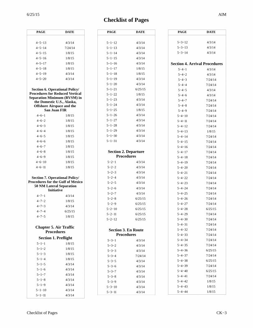
Checklist of PagesAIM
Checklist of Pages CK−1
PAGE DATE
Cover 6/25/15
Record of Changes N/A
Exp of Chg−1 6/25/15
Checklist of PagesCK−1 6/25/15
CK−2 6/25/15
CK−3 6/25/15
CK−4 6/25/15
CK−5 6/25/15
CK−6 6/25/15
Subscription Info 7/24/14
Comments/Corr 4/3/14
Comments/Corr 4/3/14
Basic Flight Info 1/8/15
Publication Policy 4/3/14
Reg & Advis Cir 4/3/14
Table of Contentsi 6/25/15
ii 6/25/15
iii 6/25/15
iv 6/25/15
v 6/25/15
vi 6/25/15
vii 6/25/15
viii 6/25/15
ix 6/25/15
x 6/25/15
xi 6/25/15
Chapter 1. Air NavigationSection 1. Navigation Aids
1−1−1 4/3/14
1−1−2 7/24/14
1−1−3 7/24/14
1−1−4 6/25/15
1−1−5 6/25/15
1−1−6 6/25/15
1−1−7 6/25/15
1−1−8 6/25/15
1−1−9 6/25/15
1−1−10 6/25/15
1−1−11 6/25/15
PAGE DATE
1−1−12 6/25/15
1−1−13 6/25/15
1−1−14 6/25/15
1−1−15 6/25/15
1−1−16 6/25/15
1−1−17 6/25/15
1−1−18 6/25/15
1−1−19 6/25/15
1−1−20 6/25/15
1−1−21 6/25/15
1−1−22 6/25/15
1−1−23 6/25/15
1−1−24 6/25/15
1−1−25 6/25/15
1−1−26 6/25/15
1−1−27 6/25/15
1−1−28 6/25/15
1−1−29 6/25/15
1−1−30 6/25/15
1−1−31 6/25/15
1−1−32 6/25/15
1−1−33 6/25/15
1−1−34 6/25/15
1−1−35 6/25/15
Section 2. Performance−BasedNavigation (PBN) and Area
Navigation (RNAV)1−2−1 1/8/15
1−2−2 1/8/15
1−2−3 1/8/15
1−2−4 1/8/15
1−2−5 1/8/15
1−2−6 1/8/15
1−2−7 1/8/15
1−2−8 1/8/15
PAGE DATE
Chapter 2. AeronauticalLighting and Other Airport
Visual AidsSection 1. Airport Lighting
Aids2−1−1 6/25/15
2−1−2 4/3/14
2−1−3 4/3/14
2−1−4 6/25/15
2−1−5 6/25/15
2−1−6 6/25/15
2−1−7 6/25/15
2−1−8 6/25/15
2−1−9 6/25/15
2−1−10 6/25/15
2−1−11 4/3/14
2−1−12 4/3/14
2−1−13 4/3/14
2−1−14 4/3/14
2−1−15 4/3/14
Section 2. Air Navigation andObstruction Lighting2−2−1 4/3/14
2−2−2 4/3/14
Section 3. Airport MarkingAids and Signs
2−3−1 4/3/14
2−3−2 4/3/14
2−3−3 4/3/14
2−3−4 4/3/14
2−3−5 4/3/14
2−3−6 4/3/14
2−3−7 7/24/14
2−3−8 4/3/14
2−3−9 4/3/14
2−3−10 4/3/14
2−3−11 4/3/14
2−3−12 7/24/14
2−3−13 4/3/14
2−3−14 4/3/14
2−3−15 4/3/14
2−3−16 4/3/14
2−3−17 4/3/14
2−3−18 4/3/14
2−3−19 4/3/14
2−3−20 4/3/14
2−3−21 4/3/14

6/25/15AIM
Checklist of Pages
Checklist of PagesCK−2
PAGE DATE
2−3−22 4/3/14
2−3−23 4/3/14
2−3−24 4/3/14
2−3−25 4/3/14
2−3−26 4/3/14
2−3−27 4/3/14
2−3−28 4/3/14
2−3−29 4/3/14
2−3−30 4/3/14
2−3−31 4/3/14
Chapter 3. AirspaceSection 1. General
3−1−1 4/3/14
3−1−2 4/3/14
Section 2. Controlled Airspace3−2−1 4/3/14
3−2−2 4/3/14
3−2−3 4/3/14
3−2−4 4/3/14
3−2−5 4/3/14
3−2−6 4/3/14
3−2−7 4/3/14
3−2−8 4/3/14
3−2−9 4/3/14
Section 3. Class G Airspace3−3−1 4/3/14
Section 4. Special Use Airspace
3−4−1 4/3/14
3−4−2 4/3/14
Section 5. Other AirspaceAreas
3−5−1 4/3/14
3−5−2 4/3/14
3−5−3 4/3/14
3−5−4 4/3/14
3−5−5 4/3/14
3−5−6 4/3/14
3−5−7 4/3/14
3−5−8 4/3/14
3−5−9 4/3/14
PAGE DATE
Chapter 4. Air Traffic ControlSection 1. Services Available
to Pilots
4−1−1 4/3/14
4−1−2 4/3/14
4−1−3 1/8/15
4−1−4 1/8/15
4−1−5 1/8/15
4−1−6 1/8/15
4−1−7 4/3/14
4−1−8 4/3/14
4−1−9 4/3/14
4−1−10 4/3/14
4−1−11 6/25/15
4−1−12 4/3/14
4−1−13 4/3/14
4−1−14 4/3/14
4−1−15 4/3/14
4−1−16 4/3/14
4−1−17 4/3/14
4−1−18 4/3/14
4−1−19 4/3/14
4−1−20 4/3/14
4−1−21 7/24/14
4−1−22 4/3/14
4−1−23 4/3/14
Section 2. RadioCommunications Phraseology
and Techniques4−2−1 4/3/14
4−2−2 4/3/14
4−2−3 4/3/14
4−2−4 4/3/14
4−2−5 4/3/14
4−2−6 4/3/14
4−2−7 4/3/14
4−2−8 4/3/14
Section 3. Airport Operations4−3−1 4/3/14
4−3−2 6/25/15
4−3−3 6/25/15
4−3−4 7/24/14
4−3−5 7/24/14
4−3−6 7/24/14
4−3−7 7/24/14
4−3−8 7/24/14
PAGE DATE
4−3−9 7/24/14
4−3−10 7/24/14
4−3−11 7/24/14
4−3−13 7/24/14
4−3−14 7/24/14
4−3−15 7/24/14
4−3−16 7/24/14
4−3−17 6/25/15
4−3−18 7/24/14
4−3−19 7/24/14
4−3−20 7/24/14
4−3−21 7/24/14
4−3−22 7/24/14
4−3−23 7/24/14
4−3−24 7/24/14
4−3−25 7/24/14
4−3−26 7/24/14
4−3−27 7/24/14
4−3−28 7/24/14
4−3−29 7/24/14
Section 4. ATC Clearancesand Aircraft Separation
4−4−1 4/3/14
4−4−2 4/3/14
4−4−3 4/3/14
4−4−4 4/3/14
4−4−5 4/3/14
4−4−6 4/3/14
4−4−7 4/3/14
4−4−8 4/3/14
4−4−9 4/3/14
4−4−10 4/3/14
4−4−11 4/3/14
Section 5. Surveillance Systems
4−5−1 4/3/14
4−5−2 4/3/14
4−5−3 4/3/14
4−5−4 4/3/14
4−5−5 4/3/14
4−5−6 4/3/14
4−5−7 4/3/14
4−5−8 4/3/14
4−5−9 4/3/14
4−5−10 4/3/14
4−5−11 4/3/14
4−5−12 4/3/14
6/25/15
Checklist of PagesAIM
Checklist of Pages CK−3
PAGE DATE
4−5−13 4/3/14
4−5−14 7/24/14
4−5−15 1/8/15
4−5−16 1/8/15
4−5−17 1/8/15
4−5−18 1/8/15
4−5−19 4/3/14
4−5−20 4/3/14
Section 6. Operational Policy/Procedures for Reduced VerticalSeparation Minimum (RVSM) in
the Domestic U.S., Alaska,Offshore Airspace and the
San Juan FIR4−6−1 1/8/15
4−6−2 1/8/15
4−6−3 1/8/15
4−6−4 1/8/15
4−6−5 1/8/15
4−6−6 1/8/15
4−6−7 1/8/15
4−6−8 1/8/15
4−6−9 1/8/15
4−6−10 1/8/15
4−6−11 1/8/15
Section 7. Operational Policy/Procedures for the Gulf of Mexico
50 NM Lateral SeparationInitiative
4−7−1 4/3/14
4−7−2 1/8/15
4−7−3 4/3/14
4−7−4 6/25/15
4−7−5 1/8/15
Chapter 5. Air Traffic Procedures
Section 1. Preflight5−1−1 1/8/15
5−1−2 1/8/15
5−1−3 1/8/15
5−1−4 1/8/15
5−1−5 4/3/14
5−1−6 4/3/14
5−1−7 4/3/14
5−1−8 4/3/14
5−1−9 4/3/14
5−1−10 4/3/14
5−1−11 4/3/14
PAGE DATE
5−1−12 4/3/14
5−1−13 4/3/14
5−1−14 4/3/14
5−1−15 4/3/14
5−1−16 4/3/14
5−1−17 1/8/15
5−1−18 1/8/15
5−1−19 4/3/14
5−1−20 4/3/14
5−1−21 6/25/15
5−1−22 1/8/15
5−1−23 4/3/14
5−1−24 4/3/14
5−1−25 1/8/15
5−1−26 4/3/14
5−1−27 4/3/14
5−1−28 4/3/14
5−1−29 4/3/14
5−1−30 4/3/14
5−1−31 4/3/14
Section 2. DepartureProcedures
5−2−1 4/3/14
5−2−2 4/3/14
5−2−3 4/3/14
5−2−4 4/3/14
5−2−5 4/3/14
5−2−6 4/3/14
5−2−7 4/3/14
5−2−8 6/25/15
5−2−9 6/25/15
5−2−10 6/25/15
5−2−11 6/25/15
5−2−12 6/25/15
Section 3. En RouteProcedures
5−3−1 4/3/14
5−3−2 4/3/14
5−3−3 4/3/14
5−3−4 7/24/14
5−3−5 4/3/14
5−3−6 4/3/14
5−3−7 4/3/14
5−3−8 4/3/14
5−3−9 4/3/14
5−3−10 4/3/14
5−3−11 4/3/14
PAGE DATE
5−3−12 4/3/14
5−3−13 4/3/14
5−3−14 4/3/14
Section 4. Arrival Procedures5−4−1 4/3/14
5−4−2 4/3/14
5−4−3 7/24/14
5−4−4 7/24/14
5−4−5 4/3/14
5−4−6 4/3/14
5−4−7 7/24/14
5−4−8 7/24/14
5−4−9 7/24/14
5−4−10 7/24/14
5−4−11 7/24/14
5−4−12 7/24/14
5−4−13 1/8/15
5−4−14 7/24/14
5−4−15 7/24/14
5−4−16 7/24/14
5−4−17 7/24/14
5−4−18 7/24/14
5−4−19 7/24/14
5−4−20 7/24/14
5−4−21 7/24/14
5−4−22 7/24/14
5−4−23 7/24/14
5−4−24 7/24/14
5−4−25 7/24/14
5−4−26 7/24/14
5−4−27 7/24/14
5−4−28 6/25/15
5−4−29 7/24/14
5−4−30 7/24/14
5−4−31 7/24/14
5−4−32 7/24/14
5−4−33 7/24/14
5−4−34 7/24/14
5−4−35 7/24/14
5−4−36 6/25/15
5−4−37 7/24/14
5−4−38 6/25/15
5−4−39 7/24/14
5−4−40 6/25/15
5−4−41 7/24/14
5−4−42 1/8/15
5−4−43 1/8/15
5−4−44 1/8/15

6/25/15AIM
Checklist of Pages
Checklist of PagesCK−4
PAGE DATE
5−4−45 1/8/15
5−4−46 1/8/15
5−4−47 1/8/15
5−4−48 1/8/15
5−4−49 6/25/15
5−4−50 6/25/15
5−4−51 7/24/14
5−4−52 7/24/14
5−4−53 7/24/14
5−4−54 7/24/14
5−4−55 7/24/14
5−4−56 7/24/14
5−4−57 7/24/14
5−4−58 7/24/14
5−4−59 7/24/14
5−4−60 7/24/14
5−4−61 7/24/14
5−4−62 7/24/14
5−4−63 7/24/14
Section 5. Pilot/ControllerRoles and Responsibilities
5−5−1 4/3/14
5−5−2 4/3/14
5−5−3 4/3/14
5−5−4 4/3/14
5−5−5 4/3/14
5−5−6 4/3/14
5−5−7 4/3/14
5−5−8 4/3/14
Section 6. National Securityand Interception Procedures
5−6−1 7/24/14
5−6−2 7/24/14
5−6−3 7/24/14
5−6−4 4/3/14
5−6−5 4/3/14
5−6−6 4/3/14
5−6−7 4/3/14
5−6−8 4/3/14
5−6−9 4/3/14
5−6−10 4/3/14
Chapter 6. Emergency Procedures
Section 1. General6−1−1 4/3/14
PAGE DATE
Section 2. Emergency ServicesAvailable to Pilots
6−2−1 4/3/14
6−2−2 4/3/14
6−2−3 4/3/14
6−2−4 4/3/14
6−2−5 4/3/14
6−2−6 4/3/14
6−2−7 4/3/14
6−2−8 4/3/14
6−2−9 4/3/14
6−2−10 4/3/14
6−2−11 4/3/14
Section 3. Distress andUrgency Procedures6−3−1 4/3/14
6−3−2 4/3/14
6−3−3 4/3/14
6−3−4 4/3/14
6−3−5 4/3/14
6−3−6 4/3/14
6−3−7 4/3/14
Section 4. Two−way RadioCommunications Failure
6−4−1 4/3/14
6−4−2 4/3/14
Section 5. Aircraft Rescueand Fire FightingCommunications
6−5−1 4/3/14
6−5−2 4/3/14
Chapter 7. Safety of FlightSection 1. Meteorology7−1−1 4/3/14
7−1−2 4/3/14
7−1−3 6/25/15
7−1−4 7/24/14
7−1−5 1/8/15
7−1−6 1/8/15
7−1−7 1/8/15
7−1−8 1/8/15
7−1−9 1/8/15
7−1−10 4/3/14
PAGE DATE
7−1−11 4/3/14
7−1−12 4/3/14
7−1−13 4/3/14
7−1−14 4/3/14
7−1−15 4/3/14
7−1−16 4/3/14
7−1−17 4/3/14
7−1−18 4/3/14
7−1−19 4/3/14
7−1−20 4/3/14
7−1−21 4/3/14
7−1−22 4/3/14
7−1−23 4/3/14
7−1−24 7/24/14
7−1−25 7/24/14
7−1−26 4/3/14
7−1−27 4/3/14
7−1−28 4/3/14
7−1−29 4/3/14
7−1−30 4/3/14
7−1−31 4/3/14
7−1−32 4/3/14
7−1−33 4/3/14
7−1−34 4/3/14
7−1−35 4/3/14
7−1−36 4/3/14
7−1−37 4/3/14
7−1−38 4/3/14
7−1−39 4/3/14
7−1−40 4/3/14
7−1−41 4/3/14
7−1−42 7/24/14
7−1−43 4/3/14
7−1−44 1/8/15
7−1−45 4/3/14
7−1−46 4/3/14
7−1−47 4/3/14
7−1−48 4/3/14
7−1−49 4/3/14
7−1−50 4/3/14
7−1−51 4/3/14
7−1−52 4/3/14
7−1−53 4/3/14
7−1−54 4/3/14
7−1−55 4/3/14
7−1−56 4/3/14
7−1−57 4/3/14
7−1−58 4/3/14
7−1−59 4/3/14

6/25/15
Checklist of PagesAIM
Checklist of Pages CK−5
PAGE DATE
7−1−60 7/24/14
7−1−61 4/3/14
7−1−62 4/3/14
7−1−63 4/3/14
7−1−64 4/3/14
7−1−65 4/3/14
7−1−66 4/3/14
7−1−67 4/3/14
7−1−68 4/3/14
7−1−69 4/3/14
7−1−70 4/3/14
7−1−71 4/3/14
7−1−72 4/3/14
Section 2. Altimeter Setting Procedures
7−2−1 4/3/14
7−2−2 4/3/14
7−2−3 1/8/15
7−2−4 4/3/14
Section 3. Wake Turbulence7−3−1 4/3/14
7−3−2 1/8/15
7−3−3 4/3/14
7−3−4 4/3/14
7−3−5 4/3/14
7−3−6 4/3/14
7−3−7 4/3/14
7−3−8 4/3/14
Section 4. Bird Hazards andFlight Over National Refuges,
Parks, and Forests7−4−1 4/3/14
7−4−2 4/3/14
Section 5. Potential FlightHazards
7−5−1 4/3/14
7−5−2 4/3/14
7−5−3 4/3/14
7−5−4 4/3/14
7−5−5 4/3/14
7−5−6 4/3/14
7−5−7 4/3/14
7−5−8 4/3/14
7−5−9 4/3/14
7−5−10 4/3/14
PAGE DATE
7−5−11 4/3/14
7−5−12 4/3/14
7−5−13 7/24/14
7−5−14 7/24/14
Section 6. Safety, Accident,and Hazard Reports7−6−1 4/3/14
7−6−2 4/3/14
7−6−3 7/24/14
Chapter 8. Medical Facts for Pilots
Section 1. Fitness for Flight8−1−1 4/3/14
8−1−2 4/3/14
8−1−3 4/3/14
8−1−4 4/3/14
8−1−5 4/3/14
8−1−6 4/3/14
8−1−7 4/3/14
8−1−8 4/3/14
8−1−9 4/3/14
Chapter 9. AeronauticalCharts and Related
PublicationsSection 1. Types of Charts
Available9−1−1 1/8/15
9−1−2 1/8/15
9−1−3 1/8/15
9−1−4 1/8/15
9−1−5 1/8/15
9−1−6 1/8/15
9−1−7 1/8/15
9−1−8 1/8/15
9−1−9 1/8/15
9−1−10 1/8/15
9−1−11 1/8/15
9−1−12 1/8/15
9−1−13 1/8/15
Chapter 10. HelicopterOperations
Section 1. Helicopter IFROperations
10−1−1 4/3/14
PAGE DATE
10−1−2 4/3/14
10−1−3 4/3/14
10−1−4 4/3/14
10−1−5 4/3/14
10−1−6 4/3/14
10−1−7 4/3/14
Section 2. Special Operations10−2−1 4/3/14
10−2−2 4/3/14
10−2−3 4/3/14
10−2−4 4/3/14
10−2−5 4/3/14
10−2−6 4/3/14
10−2−7 4/3/14
10−2−8 4/3/14
10−2−9 4/3/14
10−2−10 4/3/14
10−2−11 4/3/14
10−2−12 4/3/14
10−2−13 4/3/14
10−2−14 4/3/14
10−2−15 4/3/14
10−2−16 4/3/14
10−2−17 4/3/14
AppendicesAppendix 1−1 4/3/14
Env N/A
Appendix 2−1 4/3/14
Appendix 3−1 4/3/14
Appendix 3−2 4/3/14
Appendix 3−3 6/25/15
Appendix 3−4 6/25/15
Appendix 3−5 6/25/15
Pilot/Controller GlossaryPCG−1 6/25/15
PCG−2 7/24/14
PCG A−1 7/24/14
PCG A−2 7/24/14
PCG A−3 7/24/14
PCG A−4 7/24/14
PCG A−5 7/24/14
PGC A−6 7/24/14
PCG A−7 7/24/14
PCG A−8 7/24/14
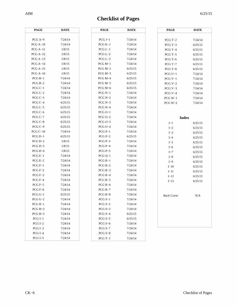
6/25/15AIM
Checklist of Pages
Checklist of PagesCK−6
PAGE DATE
PCG A−9 7/24/14
PCG A−10 7/24/14
PCG A−11 1/8/15
PCG A−12 1/8/15
PCG A−13 1/8/15
PCG A−14 1/8/15
PCG A−15 1/8/15
PCG A−16 1/8/15
PCG B−1 7/24/14
PCG B−2 7/24/14
PCG C−1 7/24/14
PCG C−2 7/24/14
PCG C−3 7/24/14
PCG C−4 6/25/15
PCG C−5 6/25/15
PCG C−6 6/25/15
PCG C−7 6/25/15
PCG C−8 6/25/15
PCG C−9 6/25/15
PCG C−10 7/24/14
PCG D−1 6/25/15
PCG D−2 1/8/15
PCG D−3 1/8/15
PCG D−4 1/8/15
PCG E−1 7/24/14
PCG E−2 7/24/14
PCG F−1 7/24/14
PCG F−2 7/24/14
PCG F−3 7/24/14
PCG F−4 7/24/14
PCG F−5 7/24/14
PCG F−6 7/24/14
PCG G−1 6/25/15
PCG G−2 7/24/14
PCG H−1 7/24/14
PCG H−2 7/24/14
PCG H−3 7/24/14
PCG I−1 7/24/14
PCG I−2 7/24/14
PCG I−3 7/24/14
PCG I−4 7/24/14
PCG I−5 7/24/14
PAGE DATE
PCG J−1 7/24/14
PCG K−1 7/24/14
PCG L−1 7/24/14
PCG L−2 7/24/14
PCG L−3 7/24/14
PCG M−1 7/24/14
PCG M−2 6/25/15
PCG M−3 6/25/15
PCG M−4 6/25/15
PCG M−5 6/25/15
PCG M−6 6/25/15
PCG N−1 7/24/14
PCG N−2 7/24/14
PCG N−3 7/24/14
PCG N−4 7/24/14
PCG O−1 7/24/14
PCG O−2 7/24/14
PCG O−3 7/24/14
PCG O−4 7/24/14
PCG P−1 7/24/14
PCG P−2 6/25/15
PCG P−3 7/24/14
PCG P−4 7/24/14
PCG P−5 7/24/14
PCG Q−1 7/24/14
PCG R−1 7/24/14
PCG R−2 7/24/14
PCG R−3 7/24/14
PCG R−4 7/24/14
PCG R−5 7/24/14
PCG R−6 7/24/14
PCG R−7 7/24/14
PCG R−8 7/24/14
PCG S−1 7/24/14
PCG S−2 7/24/14
PCG S−3 7/24/14
PCG S−4 6/25/15
PCG S−5 6/25/15
PCG S−6 7/24/14
PCG S−7 7/24/14
PCG S−8 7/24/14
PCG T−1 7/24/14
PAGE DATE
PCG T−2 7/24/14
PCG T−3 6/25/15
PCG T−4 6/25/15
PCG T−5 6/25/15
PCG T−6 6/25/15
PCG T−7 6/25/15
PCG T−8 6/25/15
PCG U−1 7/24/14
PCG V−1 7/24/14
PCG V−2 7/24/14
PCG V−3 7/24/14
PCG V−4 7/24/14
PCG W−1 7/24/14
PCG W−2 7/24/14
IndexI−1 6/25/15
I−2 6/25/15
I−3 6/25/15
I−4 6/25/15
I−5 6/25/15
I−6 6/25/15
I−7 6/25/15
I−8 6/25/15
I−9 6/25/15
I−10 6/25/15
I−11 6/25/15
I−12 6/25/15
I−13 6/25/15
Back Cover N/A
AIM6/25/15
iTable of Contents
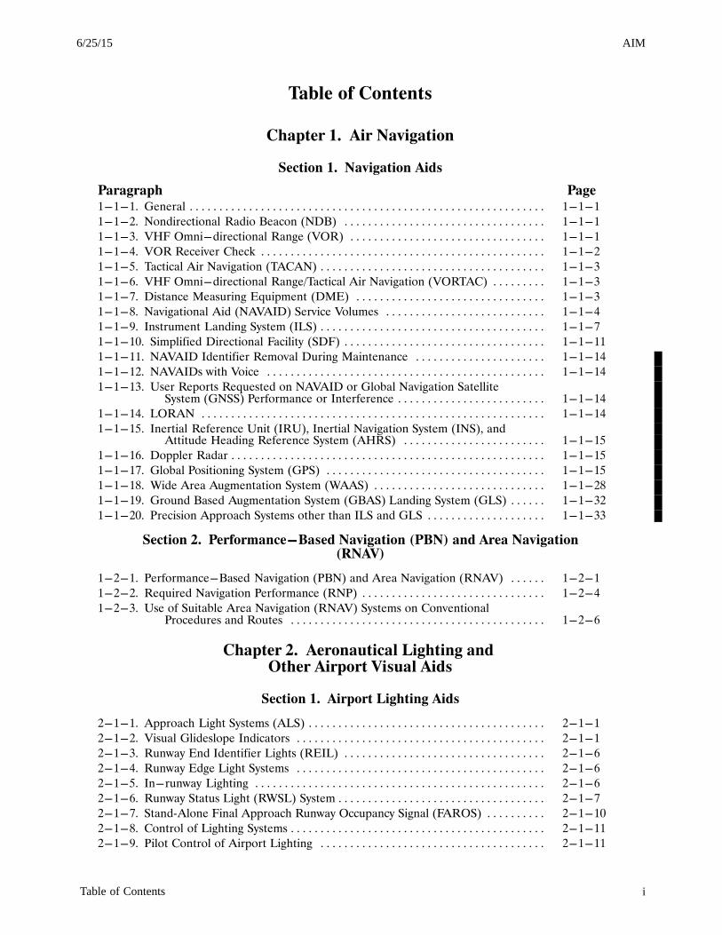
Table of Contents
Chapter 1. Air Navigation
Section 1. Navigation Aids
Paragraph Page1-1-1. General 1-1-1. . . . . . . . . . . . . . . . . . . . . . . . . . . . . . . . . . . . . . . . . . . . . . . . . . . . . . . . . . . .
1-1-2. Nondirectional Radio Beacon (NDB) 1-1-1. . . . . . . . . . . . . . . . . . . . . . . . . . . . . . . . . .
1-1-3. VHF Omni-directional Range (VOR) 1-1-1. . . . . . . . . . . . . . . . . . . . . . . . . . . . . . . . .
1-1-4. VOR Receiver Check 1-1-2. . . . . . . . . . . . . . . . . . . . . . . . . . . . . . . . . . . . . . . . . . . . . . . .
1-1-5. Tactical Air Navigation (TACAN) 1-1-3. . . . . . . . . . . . . . . . . . . . . . . . . . . . . . . . . . . . . .
1-1-6. VHF Omni-directional Range/Tactical Air Navigation (VORTAC) 1-1-3. . . . . . . . .
1-1-7. Distance Measuring Equipment (DME) 1-1-3. . . . . . . . . . . . . . . . . . . . . . . . . . . . . . . .
1-1-8. Navigational Aid (NAVAID) Service Volumes 1-1-4. . . . . . . . . . . . . . . . . . . . . . . . . . .
1-1-9. Instrument Landing System (ILS) 1-1-7. . . . . . . . . . . . . . . . . . . . . . . . . . . . . . . . . . . . . .
1-1-10. Simplified Directional Facility (SDF) 1-1-11. . . . . . . . . . . . . . . . . . . . . . . . . . . . . . . . . .
1-1-11. NAVAID Identifier Removal During Maintenance 1-1-14. . . . . . . . . . . . . . . . . . . . . .
1-1-12. NAVAIDs with Voice 1-1-14. . . . . . . . . . . . . . . . . . . . . . . . . . . . . . . . . . . . . . . . . . . . . . .
1-1-13. User Reports Requested on NAVAID or Global Navigation Satellite System (GNSS) Performance or Interference 1-1-14. . . . . . . . . . . . . . . . . . . . . . . . .
1-1-14. LORAN 1-1-14. . . . . . . . . . . . . . . . . . . . . . . . . . . . . . . . . . . . . . . . . . . . . . . . . . . . . . . . . .
1-1-15. Inertial Reference Unit (IRU), Inertial Navigation System (INS), and Attitude Heading Reference System (AHRS) 1-1-15. . . . . . . . . . . . . . . . . . . . . . . .
1-1-16. Doppler Radar 1-1-15. . . . . . . . . . . . . . . . . . . . . . . . . . . . . . . . . . . . . . . . . . . . . . . . . . . . .
1-1-17. Global Positioning System (GPS) 1-1-15. . . . . . . . . . . . . . . . . . . . . . . . . . . . . . . . . . . . .
1-1-18. Wide Area Augmentation System (WAAS) 1-1-28. . . . . . . . . . . . . . . . . . . . . . . . . . . . .
1-1-19. Ground Based Augmentation System (GBAS) Landing System (GLS) 1-1-32. . . . . .
1-1-20. Precision Approach Systems other than ILS and GLS 1-1-33. . . . . . . . . . . . . . . . . . . .
Section 2. Performance-Based Navigation (PBN) and Area Navigation(RNAV)
1-2-1. Performance-Based Navigation (PBN) and Area Navigation (RNAV) 1-2-1. . . . . .
1-2-2. Required Navigation Performance (RNP) 1-2-4. . . . . . . . . . . . . . . . . . . . . . . . . . . . . . .
1-2-3. Use of Suitable Area Navigation (RNAV) Systems on Conventional Procedures and Routes 1-2-6. . . . . . . . . . . . . . . . . . . . . . . . . . . . . . . . . . . . . . . . . . .
Chapter 2. Aeronautical Lighting and Other Airport Visual Aids
Section 1. Airport Lighting Aids
2-1-1. Approach Light Systems (ALS) 2-1-1. . . . . . . . . . . . . . . . . . . . . . . . . . . . . . . . . . . . . . . .
2-1-2. Visual Glideslope Indicators 2-1-1. . . . . . . . . . . . . . . . . . . . . . . . . . . . . . . . . . . . . . . . . .
2-1-3. Runway End Identifier Lights (REIL) 2-1-6. . . . . . . . . . . . . . . . . . . . . . . . . . . . . . . . . .
2-1-4. Runway Edge Light Systems 2-1-6. . . . . . . . . . . . . . . . . . . . . . . . . . . . . . . . . . . . . . . . . .
2-1-5. In-runway Lighting 2-1-6. . . . . . . . . . . . . . . . . . . . . . . . . . . . . . . . . . . . . . . . . . . . . . . . .
2-1-6. Runway Status Light (RWSL) System 2-1-7. . . . . . . . . . . . . . . . . . . . . . . . . . . . . . . . . . .
2-1-7. StandAlone Final Approach Runway Occupancy Signal (FAROS) 2-1-10. . . . . . . . . .
2-1-8. Control of Lighting Systems 2-1-11. . . . . . . . . . . . . . . . . . . . . . . . . . . . . . . . . . . . . . . . . . .
2-1-9. Pilot Control of Airport Lighting 2-1-11. . . . . . . . . . . . . . . . . . . . . . . . . . . . . . . . . . . . . .

AIM 6/25/15
ii Table of Contents
Paragraph Page
2-1-10. Airport/Heliport Beacons 2-1-14. . . . . . . . . . . . . . . . . . . . . . . . . . . . . . . . . . . . . . . . . . . .
2-1-11. Taxiway Lights 2-1-15. . . . . . . . . . . . . . . . . . . . . . . . . . . . . . . . . . . . . . . . . . . . . . . . . . . . .
Section 2. Air Navigation and Obstruction Lighting
2-2-1. Aeronautical Light Beacons 2-2-1. . . . . . . . . . . . . . . . . . . . . . . . . . . . . . . . . . . . . . . . . . .
2-2-2. Code Beacons and Course Lights 2-2-1. . . . . . . . . . . . . . . . . . . . . . . . . . . . . . . . . . . . . .
2-2-3. Obstruction Lights 2-2-1. . . . . . . . . . . . . . . . . . . . . . . . . . . . . . . . . . . . . . . . . . . . . . . . . .
Section 3. Airport Marking Aids and Signs
2-3-1. General 2-3-1. . . . . . . . . . . . . . . . . . . . . . . . . . . . . . . . . . . . . . . . . . . . . . . . . . . . . . . . . . . .
2-3-2. Airport Pavement Markings 2-3-1. . . . . . . . . . . . . . . . . . . . . . . . . . . . . . . . . . . . . . . . . . .
2-3-3. Runway Markings 2-3-1. . . . . . . . . . . . . . . . . . . . . . . . . . . . . . . . . . . . . . . . . . . . . . . . . . .
2-3-4. Taxiway Markings 2-3-7. . . . . . . . . . . . . . . . . . . . . . . . . . . . . . . . . . . . . . . . . . . . . . . . . . .
2-3-5. Holding Position Markings 2-3-12. . . . . . . . . . . . . . . . . . . . . . . . . . . . . . . . . . . . . . . . . . . .
2-3-6. Other Markings 2-3-16. . . . . . . . . . . . . . . . . . . . . . . . . . . . . . . . . . . . . . . . . . . . . . . . . . . . .
2-3-7. Airport Signs 2-3-19. . . . . . . . . . . . . . . . . . . . . . . . . . . . . . . . . . . . . . . . . . . . . . . . . . . . . . .
2-3-8. Mandatory Instruction Signs 2-3-20. . . . . . . . . . . . . . . . . . . . . . . . . . . . . . . . . . . . . . . . . .
2-3-9. Location Signs 2-3-23. . . . . . . . . . . . . . . . . . . . . . . . . . . . . . . . . . . . . . . . . . . . . . . . . . . . . .
2-3-10. Direction Signs 2-3-25. . . . . . . . . . . . . . . . . . . . . . . . . . . . . . . . . . . . . . . . . . . . . . . . . . . .
2-3-11. Destination Signs 2-3-28. . . . . . . . . . . . . . . . . . . . . . . . . . . . . . . . . . . . . . . . . . . . . . . . . .
2-3-12. Information Signs 2-3-29. . . . . . . . . . . . . . . . . . . . . . . . . . . . . . . . . . . . . . . . . . . . . . . . . .
2-3-13. Runway Distance Remaining Signs 2-3-29. . . . . . . . . . . . . . . . . . . . . . . . . . . . . . . . . . . .
2-3-14. Aircraft Arresting Systems 2-3-30. . . . . . . . . . . . . . . . . . . . . . . . . . . . . . . . . . . . . . . . . . .
2-3-15. Security Identifications Display Area (Airport Ramp Area) 2-3-31. . . . . . . . . . . . . . .
Chapter 3. Airspace
Section 1. General
3-1-1. General 3-1-1. . . . . . . . . . . . . . . . . . . . . . . . . . . . . . . . . . . . . . . . . . . . . . . . . . . . . . . . . . . .
3-1-2. General Dimensions of Airspace Segments 3-1-1. . . . . . . . . . . . . . . . . . . . . . . . . . . . . .
3-1-3. Hierarchy of Overlapping Airspace Designations 3-1-1. . . . . . . . . . . . . . . . . . . . . . . . .
3-1-4. Basic VFR Weather Minimums 3-1-1. . . . . . . . . . . . . . . . . . . . . . . . . . . . . . . . . . . . . . . .
3-1-5. VFR Cruising Altitudes and Flight Levels 3-1-2. . . . . . . . . . . . . . . . . . . . . . . . . . . . . . .
Section 2. Controlled Airspace
3-2-1. General 3-2-1. . . . . . . . . . . . . . . . . . . . . . . . . . . . . . . . . . . . . . . . . . . . . . . . . . . . . . . . . . . .
3-2-2. Class A Airspace 3-2-2. . . . . . . . . . . . . . . . . . . . . . . . . . . . . . . . . . . . . . . . . . . . . . . . . . . .
3-2-3. Class B Airspace 3-2-2. . . . . . . . . . . . . . . . . . . . . . . . . . . . . . . . . . . . . . . . . . . . . . . . . . . .
3-2-4. Class C Airspace 3-2-4. . . . . . . . . . . . . . . . . . . . . . . . . . . . . . . . . . . . . . . . . . . . . . . . . . . .
3-2-5. Class D Airspace 3-2-8. . . . . . . . . . . . . . . . . . . . . . . . . . . . . . . . . . . . . . . . . . . . . . . . . . . .
3-2-6. Class E Airspace 3-2-9. . . . . . . . . . . . . . . . . . . . . . . . . . . . . . . . . . . . . . . . . . . . . . . . . . . .
Section 3. Class G Airspace
3-3-1. General 3-3-1. . . . . . . . . . . . . . . . . . . . . . . . . . . . . . . . . . . . . . . . . . . . . . . . . . . . . . . . . . . .
3-3-2. VFR Requirements 3-3-1. . . . . . . . . . . . . . . . . . . . . . . . . . . . . . . . . . . . . . . . . . . . . . . . . .
3-3-3. IFR Requirements 3-3-1. . . . . . . . . . . . . . . . . . . . . . . . . . . . . . . . . . . . . . . . . . . . . . . . . .
AIM6/25/15
iiiTable of Contents
Section 4. Special Use Airspace
Paragraph Page3-4-1. General 3-4-1. . . . . . . . . . . . . . . . . . . . . . . . . . . . . . . . . . . . . . . . . . . . . . . . . . . . . . . . . . . .
3-4-2. Prohibited Areas 3-4-1. . . . . . . . . . . . . . . . . . . . . . . . . . . . . . . . . . . . . . . . . . . . . . . . . . . .
3-4-3. Restricted Areas 3-4-1. . . . . . . . . . . . . . . . . . . . . . . . . . . . . . . . . . . . . . . . . . . . . . . . . . . .
3-4-4. Warning Areas 3-4-1. . . . . . . . . . . . . . . . . . . . . . . . . . . . . . . . . . . . . . . . . . . . . . . . . . . . . .
3-4-5. Military Operations Areas 3-4-2. . . . . . . . . . . . . . . . . . . . . . . . . . . . . . . . . . . . . . . . . . . .
3-4-6. Alert Areas 3-4-2. . . . . . . . . . . . . . . . . . . . . . . . . . . . . . . . . . . . . . . . . . . . . . . . . . . . . . . . .
3-4-7. Controlled Firing Areas 3-4-2. . . . . . . . . . . . . . . . . . . . . . . . . . . . . . . . . . . . . . . . . . . . . .
3-4-8. National Security Areas 3-4-2. . . . . . . . . . . . . . . . . . . . . . . . . . . . . . . . . . . . . . . . . . . . . .
Section 5. Other Airspace Areas
3-5-1. Airport Advisory/Information Services 3-5-1. . . . . . . . . . . . . . . . . . . . . . . . . . . . . . . . . .
3-5-2. Military Training Routes 3-5-1. . . . . . . . . . . . . . . . . . . . . . . . . . . . . . . . . . . . . . . . . . . . .
3-5-3. Temporary Flight Restrictions 3-5-2. . . . . . . . . . . . . . . . . . . . . . . . . . . . . . . . . . . . . . . . .
3-5-4. Parachute Jump Aircraft Operations 3-5-5. . . . . . . . . . . . . . . . . . . . . . . . . . . . . . . . . . .
3-5-5. Published VFR Routes 3-5-5. . . . . . . . . . . . . . . . . . . . . . . . . . . . . . . . . . . . . . . . . . . . . . .
3-5-6. Terminal Radar Service Area (TRSA) 3-5-9. . . . . . . . . . . . . . . . . . . . . . . . . . . . . . . . . .
Chapter 4. Air Traffic Control
Section 1. Services Available to Pilots
4-1-1. Air Route Traffic Control Centers 4-1-1. . . . . . . . . . . . . . . . . . . . . . . . . . . . . . . . . . . . .
4-1-2. Control Towers 4-1-1. . . . . . . . . . . . . . . . . . . . . . . . . . . . . . . . . . . . . . . . . . . . . . . . . . . . .
4-1-3. Flight Service Stations 4-1-1. . . . . . . . . . . . . . . . . . . . . . . . . . . . . . . . . . . . . . . . . . . . . . .
4-1-4. Recording and Monitoring 4-1-1. . . . . . . . . . . . . . . . . . . . . . . . . . . . . . . . . . . . . . . . . . . .
4-1-5. Communications Release of IFR Aircraft Landing at an Airport Without an Operating Control Tower 4-1-1. . . . . . . . . . . . . . . . . . . . . . . . . . . . . . . . . . . . . . .
4-1-6. Pilot Visits to Air Traffic Facilities 4-1-1. . . . . . . . . . . . . . . . . . . . . . . . . . . . . . . . . . . . .
4-1-7. Operation Take‐off and Operation Raincheck 4-1-2. . . . . . . . . . . . . . . . . . . . . . . . . . .
4-1-8. Approach Control Service for VFR Arriving Aircraft 4-1-2. . . . . . . . . . . . . . . . . . . . .
4-1-9. Traffic Advisory Practices at Airports Without Operating Control Towers 4-1-2. . . .
4-1-10. IFR Approaches/Ground Vehicle Operations 4-1-6. . . . . . . . . . . . . . . . . . . . . . . . . . .
4-1-11. Designated UNICOM/MULTICOM Frequencies 4-1-6. . . . . . . . . . . . . . . . . . . . . . .
4-1-12. Use of UNICOM for ATC Purposes 4-1-7. . . . . . . . . . . . . . . . . . . . . . . . . . . . . . . . . . .
4-1-13. Automatic Terminal Information Service (ATIS) 4-1-7. . . . . . . . . . . . . . . . . . . . . . . .
4-1-14. Automatic Flight Information Service (AFIS) - Alaska FSSs Only 4-1-8. . . . . . . . .
4-1-15. Radar Traffic Information Service 4-1-8. . . . . . . . . . . . . . . . . . . . . . . . . . . . . . . . . . . .
4-1-16. Safety Alert 4-1-10. . . . . . . . . . . . . . . . . . . . . . . . . . . . . . . . . . . . . . . . . . . . . . . . . . . . . . .
4-1-17. Radar Assistance to VFR Aircraft 4-1-11. . . . . . . . . . . . . . . . . . . . . . . . . . . . . . . . . . . .
4-1-18. Terminal Radar Services for VFR Aircraft 4-1-12. . . . . . . . . . . . . . . . . . . . . . . . . . . . .
4-1-19. Tower En Route Control (TEC) 4-1-14. . . . . . . . . . . . . . . . . . . . . . . . . . . . . . . . . . . . . .
4-1-20. Transponder Operation 4-1-15. . . . . . . . . . . . . . . . . . . . . . . . . . . . . . . . . . . . . . . . . . . . .
4-1-21. Hazardous Area Reporting Service 4-1-18. . . . . . . . . . . . . . . . . . . . . . . . . . . . . . . . . . . .
4-1-22. Airport Reservation Operations and Special Traffic Management Programs 4-1-21.
4-1-23. Requests for Waivers and Authorizations from Title 14, Code of Federal Regulations (14 CFR) 4-1-23. . . . . . . . . . . . . . . . . . . . . . . . . . . . . . . . . . . . . . . . . . . .
4-1-24. Weather System Processor 4-1-23. . . . . . . . . . . . . . . . . . . . . . . . . . . . . . . . . . . . . . . . . . .
AIM 6/25/15
iv Table of Contents
Section 2. Radio Communications Phraseology and Techniques
Paragraph Page
4-2-1. General 4-2-1. . . . . . . . . . . . . . . . . . . . . . . . . . . . . . . . . . . . . . . . . . . . . . . . . . . . . . . . . . . .
4-2-2. Radio Technique 4-2-1. . . . . . . . . . . . . . . . . . . . . . . . . . . . . . . . . . . . . . . . . . . . . . . . . . . .
4-2-3. Contact Procedures 4-2-1. . . . . . . . . . . . . . . . . . . . . . . . . . . . . . . . . . . . . . . . . . . . . . . . . .
4-2-4. Aircraft Call Signs 4-2-3. . . . . . . . . . . . . . . . . . . . . . . . . . . . . . . . . . . . . . . . . . . . . . . . . . .
4-2-5. Description of Interchange or Leased Aircraft 4-2-4. . . . . . . . . . . . . . . . . . . . . . . . . . .
4-2-6. Ground Station Call Signs 4-2-4. . . . . . . . . . . . . . . . . . . . . . . . . . . . . . . . . . . . . . . . . . . .
4-2-7. Phonetic Alphabet 4-2-5. . . . . . . . . . . . . . . . . . . . . . . . . . . . . . . . . . . . . . . . . . . . . . . . . . .
4-2-8. Figures 4-2-6. . . . . . . . . . . . . . . . . . . . . . . . . . . . . . . . . . . . . . . . . . . . . . . . . . . . . . . . . . . .
4-2-9. Altitudes and Flight Levels 4-2-6. . . . . . . . . . . . . . . . . . . . . . . . . . . . . . . . . . . . . . . . . . .
4-2-10. Directions 4-2-6. . . . . . . . . . . . . . . . . . . . . . . . . . . . . . . . . . . . . . . . . . . . . . . . . . . . . . . . .
4-2-11. Speeds 4-2-6. . . . . . . . . . . . . . . . . . . . . . . . . . . . . . . . . . . . . . . . . . . . . . . . . . . . . . . . . . . .
4-2-12. Time 4-2-6. . . . . . . . . . . . . . . . . . . . . . . . . . . . . . . . . . . . . . . . . . . . . . . . . . . . . . . . . . . . .
4-2-13. Communications with Tower when Aircraft Transmitter or Receiver or Both are Inoperative 4-2-7. . . . . . . . . . . . . . . . . . . . . . . . . . . . . . . . . . . . . . . . . . . . .
4-2-14. Communications for VFR Flights 4-2-8. . . . . . . . . . . . . . . . . . . . . . . . . . . . . . . . . . . . .
Section 3. Airport Operations
4-3-1. General 4-3-1. . . . . . . . . . . . . . . . . . . . . . . . . . . . . . . . . . . . . . . . . . . . . . . . . . . . . . . . . . . .
4-3-2. Airports with an Operating Control Tower 4-3-1. . . . . . . . . . . . . . . . . . . . . . . . . . . . . .
4-3-3. Traffic Patterns 4-3-2. . . . . . . . . . . . . . . . . . . . . . . . . . . . . . . . . . . . . . . . . . . . . . . . . . . . .
4-3-4. Visual Indicators at Airports Without an Operating Control Tower 4-3-6. . . . . . . . . .
4-3-5. Unexpected Maneuvers in the Airport Traffic Pattern 4-3-7. . . . . . . . . . . . . . . . . . . . .
4-3-6. Use of Runways/Declared Distances 4-3-7. . . . . . . . . . . . . . . . . . . . . . . . . . . . . . . . . . . .
4-3-7. Low Level Wind Shear/Microburst Detection Systems 4-3-12. . . . . . . . . . . . . . . . . . . .
4-3-8. Braking Action Reports and Advisories 4-3-12. . . . . . . . . . . . . . . . . . . . . . . . . . . . . . . . .
4-3-9. Runway Friction Reports and Advisories 4-3-12. . . . . . . . . . . . . . . . . . . . . . . . . . . . . . . .
4-3-10. Intersection Takeoffs 4-3-13. . . . . . . . . . . . . . . . . . . . . . . . . . . . . . . . . . . . . . . . . . . . . . .
4-3-11. Pilot Responsibilities When Conducting Land and Hold Short Operations (LAHSO) 4-3-14. . . . . . . . . . . . . . . . . . . . . . . . . . . . . . . . . . . . . . . . . . . .
4-3-12. Low Approach 4-3-16. . . . . . . . . . . . . . . . . . . . . . . . . . . . . . . . . . . . . . . . . . . . . . . . . . . . .
4-3-13. Traffic Control Light Signals 4-3-16. . . . . . . . . . . . . . . . . . . . . . . . . . . . . . . . . . . . . . . . .
4-3-14. Communications 4-3-17. . . . . . . . . . . . . . . . . . . . . . . . . . . . . . . . . . . . . . . . . . . . . . . . . . .
4-3-15. Gate Holding Due to Departure Delays 4-3-18. . . . . . . . . . . . . . . . . . . . . . . . . . . . . . .
4-3-16. VFR Flights in Terminal Areas 4-3-18. . . . . . . . . . . . . . . . . . . . . . . . . . . . . . . . . . . . . . .
4-3-17. VFR Helicopter Operations at Controlled Airports 4-3-18. . . . . . . . . . . . . . . . . . . . . .
4-3-18. Taxiing 4-3-20. . . . . . . . . . . . . . . . . . . . . . . . . . . . . . . . . . . . . . . . . . . . . . . . . . . . . . . . . . .
4-3-19. Taxi During Low Visibility 4-3-21. . . . . . . . . . . . . . . . . . . . . . . . . . . . . . . . . . . . . . . . . . .
4-3-20. Exiting the Runway After Landing 4-3-22. . . . . . . . . . . . . . . . . . . . . . . . . . . . . . . . . . . .
4-3-21. Practice Instrument Approaches 4-3-22. . . . . . . . . . . . . . . . . . . . . . . . . . . . . . . . . . . . . .
4-3-22. Option Approach 4-3-24. . . . . . . . . . . . . . . . . . . . . . . . . . . . . . . . . . . . . . . . . . . . . . . . . .
4-3-23. Use of Aircraft Lights 4-3-24. . . . . . . . . . . . . . . . . . . . . . . . . . . . . . . . . . . . . . . . . . . . . . .
4-3-24. Flight Inspection/`Flight Check' Aircraft in Terminal Areas 4-3-25. . . . . . . . . . . . . . .
4-3-25. Hand Signals 4-3-25. . . . . . . . . . . . . . . . . . . . . . . . . . . . . . . . . . . . . . . . . . . . . . . . . . . . . .
4-3-26. Operations at Uncontrolled Airports With Automated Surface Observing System (ASOS)/Automated Weather Sensor System(AWSS)/Automated Weather Observing System (AWOS) 4-3-29. . . . . . . . . . . . . . . . . . . . . . . . . . . . . . . .
AIM6/25/15
vTable of Contents
Section 4. ATC Clearances and Aircraft Separation
Paragraph Page
4-4-1. Clearance 4-4-1. . . . . . . . . . . . . . . . . . . . . . . . . . . . . . . . . . . . . . . . . . . . . . . . . . . . . . . . . .
4-4-2. Clearance Prefix 4-4-1. . . . . . . . . . . . . . . . . . . . . . . . . . . . . . . . . . . . . . . . . . . . . . . . . . . .
4-4-3. Clearance Items 4-4-1. . . . . . . . . . . . . . . . . . . . . . . . . . . . . . . . . . . . . . . . . . . . . . . . . . . . .
4-4-4. Amended Clearances 4-4-2. . . . . . . . . . . . . . . . . . . . . . . . . . . . . . . . . . . . . . . . . . . . . . . .
4-4-5. Coded Departure Route (CDR) 4-4-3. . . . . . . . . . . . . . . . . . . . . . . . . . . . . . . . . . . . . . .
4-4-6. Special VFR Clearances 4-4-3. . . . . . . . . . . . . . . . . . . . . . . . . . . . . . . . . . . . . . . . . . . . . .
4-4-7. Pilot Responsibility upon Clearance Issuance 4-4-4. . . . . . . . . . . . . . . . . . . . . . . . . . . .
4-4-8. IFR Clearance VFR-on-top 4-4-4. . . . . . . . . . . . . . . . . . . . . . . . . . . . . . . . . . . . . . . . .
4-4-9. VFR/IFR Flights 4-4-5. . . . . . . . . . . . . . . . . . . . . . . . . . . . . . . . . . . . . . . . . . . . . . . . . . . .
4-4-10. Adherence to Clearance 4-4-5. . . . . . . . . . . . . . . . . . . . . . . . . . . . . . . . . . . . . . . . . . . . .
4-4-11. IFR Separation Standards 4-4-7. . . . . . . . . . . . . . . . . . . . . . . . . . . . . . . . . . . . . . . . . . .
4-4-12. Speed Adjustments 4-4-7. . . . . . . . . . . . . . . . . . . . . . . . . . . . . . . . . . . . . . . . . . . . . . . . .
4-4-13. Runway Separation 4-4-9. . . . . . . . . . . . . . . . . . . . . . . . . . . . . . . . . . . . . . . . . . . . . . . . .
4-4-14. Visual Separation 4-4-10. . . . . . . . . . . . . . . . . . . . . . . . . . . . . . . . . . . . . . . . . . . . . . . . . .
4-4-15. Use of Visual Clearing Procedures 4-4-10. . . . . . . . . . . . . . . . . . . . . . . . . . . . . . . . . . . .
4-4-16. Traffic Alert and Collision Avoidance System (TCAS I & II) 4-4-11. . . . . . . . . . . . . .
4-4-17. Traffic Information Service (TIS) 4-4-11. . . . . . . . . . . . . . . . . . . . . . . . . . . . . . . . . . . . .
Section 5. Surveillance Systems
4-5-1. Radar 4-5-1. . . . . . . . . . . . . . . . . . . . . . . . . . . . . . . . . . . . . . . . . . . . . . . . . . . . . . . . . . . . .
4-5-2. Air Traffic Control Radar Beacon System (ATCRBS) 4-5-2. . . . . . . . . . . . . . . . . . . . .
4-5-3. Surveillance Radar 4-5-7. . . . . . . . . . . . . . . . . . . . . . . . . . . . . . . . . . . . . . . . . . . . . . . . . .
4-5-4. Precision Approach Radar (PAR) 4-5-7. . . . . . . . . . . . . . . . . . . . . . . . . . . . . . . . . . . . . .
4-5-5. Airport Surface Detection Equipment - Model X (ASDE-X) 4-5-7. . . . . . . . . . . .
4-5-6. Traffic Information Service (TIS) 4-5-8. . . . . . . . . . . . . . . . . . . . . . . . . . . . . . . . . . . . . .
4-5-7. Automatic Dependent Surveillance-Broadcast (ADS-B) Services 4-5-14. . . . . . . . .
4-5-8. Traffic Information Service- Broadcast (TIS-B) 4-5-17. . . . . . . . . . . . . . . . . . . . . . . .
4-5-9. Flight Information Service- Broadcast (FIS-B) 4-5-18. . . . . . . . . . . . . . . . . . . . . . . . .
4-5-10. Automatic Dependent Surveillance-Rebroadcast (ADS-R) 4-5-20. . . . . . . . . . . . . .
Section 6. Operational Policy/Procedures for Reduced VerticalSeparation Minimum (RVSM) in the Domestic U.S., Alaska, Offshore
Airspace and the San Juan FIR
4-6-1. Applicability and RVSM Mandate (Date/Time and Area) 4-6-1. . . . . . . . . . . . . . . . .
4-6-2. Flight Level Orientation Scheme 4-6-1. . . . . . . . . . . . . . . . . . . . . . . . . . . . . . . . . . . . . .
4-6-3. Aircraft and Operator Approval Policy/Procedures, RVSM Monitoring and Databases for Aircraft and Operator Approval 4-6-2. . . . . . . . . . . . . . . . . . . . . . .
4-6-4. Flight Planning into RVSM Airspace 4-6-3. . . . . . . . . . . . . . . . . . . . . . . . . . . . . . . . . . .
4-6-5. Pilot RVSM Operating Practices and Procedures 4-6-3. . . . . . . . . . . . . . . . . . . . . . . . .
4-6-6. Guidance on Severe Turbulence and Mountain Wave Activity (MWA) 4-6-4. . . . . . .
4-6-7. Guidance on Wake Turbulence 4-6-5. . . . . . . . . . . . . . . . . . . . . . . . . . . . . . . . . . . . . . . .
4-6-8. Pilot/Controller Phraseology 4-6-6. . . . . . . . . . . . . . . . . . . . . . . . . . . . . . . . . . . . . . . . . .
4-6-9. Contingency Actions: Weather Encounters and Aircraft System Failures that Occur After Entry into RVSM Airspace 4-6-8. . . . . . . . . . . . . . . . . . . . . . . . . . . . .
4-6-10. Procedures for Accommodation of Non-RVSM Aircraft 4-6-10. . . . . . . . . . . . . . . . .
4-6-11. Non-RVSM Aircraft Requesting Climb to and Descent from Flight Levels Above RVSM Airspace Without Intermediate Level Off 4-6-11. . . . . . . . . . . . . . .
AIM 6/25/15
vi Table of Contents
Section 7. Operational Policy/Procedures for the Gulf of Mexico 50 NMLateral Separation Initiative
Paragraph Page
4-7-1. Introduction and Background 4-7-1. . . . . . . . . . . . . . . . . . . . . . . . . . . . . . . . . . . . . . . . .
4-7-2. Gulf of Mexico 50 NM Lateral Separation Initiative Web Page: Policy, Procedures and Guidance for Operators and Regulators 4-7-1. . . . . . . . . . . . . . .
4-7-3. Lateral Separation Minima Applied 4-7-1. . . . . . . . . . . . . . . . . . . . . . . . . . . . . . . . . . . .
4-7-4. Operation on Routes on the periphery of the Gulf of Mexico CTAs 4-7-2. . . . . . . . .
4-7-5. Provisions for Accommodation of NonRNP10 Aircraft (Aircraft Not Authorized RNP 10 or RNP 4) 4-7-2. . . . . . . . . . . . . . . . . . . . . . . . . . . . . . . . . . . . .
4-7-6. Operator Action 4-7-2. . . . . . . . . . . . . . . . . . . . . . . . . . . . . . . . . . . . . . . . . . . . . . . . . . . .
4-7-7. RNP 10 or RNP 4 Authorization: Policy and Procedures for Aircraft and Operators 4-7-2. . . . . . . . . . . . . . . . . . . . . . . . . . . . . . . . . . . . . . . . . . . . . . . . . . . . . .
4-7-8. Flight Planning Requirements 4-7-4. . . . . . . . . . . . . . . . . . . . . . . . . . . . . . . . . . . . . . . . .
4-7-9. Pilot and Dispatcher Procedures: Basic and Inflight Contingency Procedures 4-7-4.
Chapter 5. Air Traffic Procedures
Section 1. Preflight
5-1-1. Preflight Preparation 5-1-1. . . . . . . . . . . . . . . . . . . . . . . . . . . . . . . . . . . . . . . . . . . . . . . .
5-1-2. Follow IFR Procedures Even When Operating VFR 5-1-2. . . . . . . . . . . . . . . . . . . . . .
5-1-3. Notice to Airmen (NOTAM) System 5-1-2. . . . . . . . . . . . . . . . . . . . . . . . . . . . . . . . . . .
5-1-4. Flight Plan - VFR Flights 5-1-7. . . . . . . . . . . . . . . . . . . . . . . . . . . . . . . . . . . . . . . . . . . .
5-1-5. Operational Information System (OIS) 5-1-10. . . . . . . . . . . . . . . . . . . . . . . . . . . . . . . . .
5-1-6. Flight Plan- Defense VFR (DVFR) Flights 5-1-10. . . . . . . . . . . . . . . . . . . . . . . . . . . . .
5-1-7. Composite Flight Plan (VFR/IFR Flights) 5-1-11. . . . . . . . . . . . . . . . . . . . . . . . . . . . . . .
5-1-8. Flight Plan (FAA Form 7233-1)- Domestic IFR Flights 5-1-11. . . . . . . . . . . . . . . . . .
5-1-9. International Flight Plan (FAA Form 7233-4)- IFR Flights (For Domestic or International Flights) 5-1-17. . . . . . . . . . . . . . . . . . . . . . . . . . . . . . . . . . . . . . . . . .
5-1-10. IFR Operations to High Altitude Destinations 5-1-27. . . . . . . . . . . . . . . . . . . . . . . . . .
5-1-11. Flights Outside the U.S. and U.S. Territories 5-1-28. . . . . . . . . . . . . . . . . . . . . . . . . . .
5-1-12. Change in Flight Plan 5-1-30. . . . . . . . . . . . . . . . . . . . . . . . . . . . . . . . . . . . . . . . . . . . . . .
5-1-13. Change in Proposed Departure Time 5-1-30. . . . . . . . . . . . . . . . . . . . . . . . . . . . . . . . . .
5-1-14. Closing VFR/DVFR Flight Plans 5-1-30. . . . . . . . . . . . . . . . . . . . . . . . . . . . . . . . . . . . .
5-1-15. Canceling IFR Flight Plan 5-1-30. . . . . . . . . . . . . . . . . . . . . . . . . . . . . . . . . . . . . . . . . . .
5-1-16. RNAV and RNP Operations 5-1-30. . . . . . . . . . . . . . . . . . . . . . . . . . . . . . . . . . . . . . . . .
Section 2. Departure Procedures
5-2-1. Pre‐taxi Clearance Procedures 5-2-1. . . . . . . . . . . . . . . . . . . . . . . . . . . . . . . . . . . . . . . . .
5-2-2. Pre-departure Clearance Procedures 5-2-1. . . . . . . . . . . . . . . . . . . . . . . . . . . . . . . . . .
5-2-3. Taxi Clearance 5-2-1. . . . . . . . . . . . . . . . . . . . . . . . . . . . . . . . . . . . . . . . . . . . . . . . . . . . . .
5-2-4. Line Up and Wait (LUAW) 5-2-1. . . . . . . . . . . . . . . . . . . . . . . . . . . . . . . . . . . . . . . . . . .
5-2-5. Abbreviated IFR Departure Clearance (Cleared. . .as Filed) Procedures 5-2-2. . . . .
5-2-6. Departure Restrictions, Clearance Void Times, Hold for Release, and Release Times 5-2-4. . . . . . . . . . . . . . . . . . . . . . . . . . . . . . . . . . . . . . . . . . . . . . . . . . .
5-2-7. Departure Control 5-2-5. . . . . . . . . . . . . . . . . . . . . . . . . . . . . . . . . . . . . . . . . . . . . . . . . .
5-2-8. Instrument Departure Procedures (DP) - Obstacle Departure Procedures (ODP) and Standard Instrument Departures (SID) 5-2-5. . . . . . . . . . . . . . . . . . .
AIM6/25/15
viiTable of Contents
Section 3. En Route Procedures
Paragraph Page5-3-1. ARTCC Communications 5-3-1. . . . . . . . . . . . . . . . . . . . . . . . . . . . . . . . . . . . . . . . . . . .
5-3-2. Position Reporting 5-3-3. . . . . . . . . . . . . . . . . . . . . . . . . . . . . . . . . . . . . . . . . . . . . . . . . .
5-3-3. Additional Reports 5-3-4. . . . . . . . . . . . . . . . . . . . . . . . . . . . . . . . . . . . . . . . . . . . . . . . . .
5-3-4. Airways and Route Systems 5-3-5. . . . . . . . . . . . . . . . . . . . . . . . . . . . . . . . . . . . . . . . . . .
5-3-5. Airway or Route Course Changes 5-3-7. . . . . . . . . . . . . . . . . . . . . . . . . . . . . . . . . . . . . .
5-3-6. Changeover Points (COPs) 5-3-8. . . . . . . . . . . . . . . . . . . . . . . . . . . . . . . . . . . . . . . . . . .
5-3-7. Minimum Turning Altitude (MTA) 5-3-8. . . . . . . . . . . . . . . . . . . . . . . . . . . . . . . . . . . . .
5-3-8. Holding 5-3-8. . . . . . . . . . . . . . . . . . . . . . . . . . . . . . . . . . . . . . . . . . . . . . . . . . . . . . . . . . . .
Section 4. Arrival Procedures
5-4-1. Standard Terminal Arrival (STAR) Procedures 5-4-1. . . . . . . . . . . . . . . . . . . . . . . . . . .
5-4-2. Local Flow Traffic Management Program 5-4-3. . . . . . . . . . . . . . . . . . . . . . . . . . . . . . .
5-4-3. Approach Control 5-4-3. . . . . . . . . . . . . . . . . . . . . . . . . . . . . . . . . . . . . . . . . . . . . . . . . . .
5-4-4. Advance Information on Instrument Approach 5-4-4. . . . . . . . . . . . . . . . . . . . . . . . . .
5-4-5. Instrument Approach Procedure Charts 5-4-5. . . . . . . . . . . . . . . . . . . . . . . . . . . . . . . .
5-4-6. Approach Clearance 5-4-24. . . . . . . . . . . . . . . . . . . . . . . . . . . . . . . . . . . . . . . . . . . . . . . . .
5-4-7. Instrument Approach Procedures 5-4-26. . . . . . . . . . . . . . . . . . . . . . . . . . . . . . . . . . . . . .
5-4-8. Special Instrument Approach Procedures 5-4-27. . . . . . . . . . . . . . . . . . . . . . . . . . . . . . .
5-4-9. Procedure Turn and Hold-in-lieu of Procedure Turn 5-4-28. . . . . . . . . . . . . . . . . . . .
5-4-10. Timed Approaches from a Holding Fix 5-4-31. . . . . . . . . . . . . . . . . . . . . . . . . . . . . . . .
5-4-11. Radar Approaches 5-4-34. . . . . . . . . . . . . . . . . . . . . . . . . . . . . . . . . . . . . . . . . . . . . . . . .
5-4-12. Radar Monitoring of Instrument Approaches 5-4-35. . . . . . . . . . . . . . . . . . . . . . . . . . .
5-4-13. ILS Approaches to Parallel Runways 5-4-36. . . . . . . . . . . . . . . . . . . . . . . . . . . . . . . . . .
5-4-14. Parallel ILS Approaches (Dependent) (See FIG 5-4-19.) 5-4-38. . . . . . . . . . . . . . . . . . . . . . . . . . . . . . . . . . . . . . . . . . . . . .
5-4-15. Simultaneous (Parallel) Independent ILS/RNAV/GLS Approaches(See FIG 5-4-20.) 5-4-40. . . . . . . . . . . . . . . . . . . . . . . . . . . . . . . . . . . . . . . . . . . . . .
5-4-16. Simultaneous Close Parallel ILS PRM/RNAV PRM/GLS PRM Approaches and Simultaneous Offset Instrument Approaches (SOIA)(See FIG 5-4-21.) 5-4-42. . . . . . . . . . . . . . . . . . . . . . . . . . . . . . . . . . . . . . . . . . . . . .
5-4-17. Simultaneous Converging Instrument Approaches 5-4-49. . . . . . . . . . . . . . . . . . . . . . .
5-4-18. RNP AR Instrument Approach Procedures 5-4-50. . . . . . . . . . . . . . . . . . . . . . . . . . . . .
5-4-19. Side-step Maneuver 5-4-52. . . . . . . . . . . . . . . . . . . . . . . . . . . . . . . . . . . . . . . . . . . . . . .
5-4-20. Approach and Landing Minimums 5-4-52. . . . . . . . . . . . . . . . . . . . . . . . . . . . . . . . . . . .
5-4-21. Missed Approach 5-4-55. . . . . . . . . . . . . . . . . . . . . . . . . . . . . . . . . . . . . . . . . . . . . . . . . .
5-4-22. Use of Enhanced Flight Vision Systems (EFVS) on Instrument Approaches 5-4-58.
5-4-23. Visual Approach 5-4-60. . . . . . . . . . . . . . . . . . . . . . . . . . . . . . . . . . . . . . . . . . . . . . . . . . .
5-4-24. Charted Visual Flight Procedure (CVFP) 5-4-61. . . . . . . . . . . . . . . . . . . . . . . . . . . . . .
5-4-25. Contact Approach 5-4-62. . . . . . . . . . . . . . . . . . . . . . . . . . . . . . . . . . . . . . . . . . . . . . . . . .
5-4-26. Landing Priority 5-4-62. . . . . . . . . . . . . . . . . . . . . . . . . . . . . . . . . . . . . . . . . . . . . . . . . . .
5-4-27. Overhead Approach Maneuver 5-4-62. . . . . . . . . . . . . . . . . . . . . . . . . . . . . . . . . . . . . . .
Section 5. Pilot/Controller Roles and Responsibilities
5-5-1. General 5-5-1. . . . . . . . . . . . . . . . . . . . . . . . . . . . . . . . . . . . . . . . . . . . . . . . . . . . . . . . . . . .
5-5-2. Air Traffic Clearance 5-5-1. . . . . . . . . . . . . . . . . . . . . . . . . . . . . . . . . . . . . . . . . . . . . . . .
5-5-3. Contact Approach 5-5-2. . . . . . . . . . . . . . . . . . . . . . . . . . . . . . . . . . . . . . . . . . . . . . . . . . .
5-5-4. Instrument Approach 5-5-2. . . . . . . . . . . . . . . . . . . . . . . . . . . . . . . . . . . . . . . . . . . . . . . .
5-5-5. Missed Approach 5-5-2. . . . . . . . . . . . . . . . . . . . . . . . . . . . . . . . . . . . . . . . . . . . . . . . . . .
5-5-6. Radar Vectors 5-5-3. . . . . . . . . . . . . . . . . . . . . . . . . . . . . . . . . . . . . . . . . . . . . . . . . . . . . .

AIM 6/25/15
viii Table of Contents
Paragraph Page5-5-7. Safety Alert 5-5-3. . . . . . . . . . . . . . . . . . . . . . . . . . . . . . . . . . . . . . . . . . . . . . . . . . . . . . . .
5-5-8. See and Avoid 5-5-4. . . . . . . . . . . . . . . . . . . . . . . . . . . . . . . . . . . . . . . . . . . . . . . . . . . . . .
5-5-9. Speed Adjustments 5-5-4. . . . . . . . . . . . . . . . . . . . . . . . . . . . . . . . . . . . . . . . . . . . . . . . . .
5-5-10. Traffic Advisories (Traffic Information) 5-5-4. . . . . . . . . . . . . . . . . . . . . . . . . . . . . . . .
5-5-11. Visual Approach 5-5-5. . . . . . . . . . . . . . . . . . . . . . . . . . . . . . . . . . . . . . . . . . . . . . . . . . .
5-5-12. Visual Separation 5-5-5. . . . . . . . . . . . . . . . . . . . . . . . . . . . . . . . . . . . . . . . . . . . . . . . . .
5-5-13. VFR‐on‐top 5-5-6. . . . . . . . . . . . . . . . . . . . . . . . . . . . . . . . . . . . . . . . . . . . . . . . . . . . . . .
5-5-14. Instrument Departures 5-5-6. . . . . . . . . . . . . . . . . . . . . . . . . . . . . . . . . . . . . . . . . . . . . .
5-5-15. Minimum Fuel Advisory 5-5-7. . . . . . . . . . . . . . . . . . . . . . . . . . . . . . . . . . . . . . . . . . . . .
5-5-16. RNAV and RNP Operations 5-5-7. . . . . . . . . . . . . . . . . . . . . . . . . . . . . . . . . . . . . . . . .
Section 6. National Security and Interception Procedures
5-6-1. National Security 5-6-1. . . . . . . . . . . . . . . . . . . . . . . . . . . . . . . . . . . . . . . . . . . . . . . . . . . .
5-6-2. Interception Procedures 5-6-2. . . . . . . . . . . . . . . . . . . . . . . . . . . . . . . . . . . . . . . . . . . . . .
5-6-3. Law Enforcement Operations by Civil and Military Organizations 5-6-6. . . . . . . . . .
5-6-4. Interception Signals 5-6-7. . . . . . . . . . . . . . . . . . . . . . . . . . . . . . . . . . . . . . . . . . . . . . . . .
5-6-5. ADIZ Boundaries and Designated Mountainous Areas (See FIG 5-6-3.) 5-6-9. . . . . . . . . . . . . . . . . . . . . . . . . . . . . . . . . . . . . . . . . . . . . . .
5-6-6. Visual Warning System (VWS) 5-6-10. . . . . . . . . . . . . . . . . . . . . . . . . . . . . . . . . . . . . . . .
Chapter 6. Emergency Procedures
Section 1. General
6-1-1. Pilot Responsibility and Authority 6-1-1. . . . . . . . . . . . . . . . . . . . . . . . . . . . . . . . . . . . .
6-1-2. Emergency Condition- Request Assistance Immediately 6-1-1. . . . . . . . . . . . . . . . . .
Section 2. Emergency Services Available to Pilots
6-2-1. Radar Service for VFR Aircraft in Difficulty 6-2-1. . . . . . . . . . . . . . . . . . . . . . . . . . . .
6-2-2. Transponder Emergency Operation 6-2-1. . . . . . . . . . . . . . . . . . . . . . . . . . . . . . . . . . . .
6-2-3. Intercept and Escort 6-2-1. . . . . . . . . . . . . . . . . . . . . . . . . . . . . . . . . . . . . . . . . . . . . . . . .
6-2-4. Emergency Locator Transmitter (ELT) 6-2-2. . . . . . . . . . . . . . . . . . . . . . . . . . . . . . . . .
6-2-5. FAA K-9 Explosives Detection Team Program 6-2-3. . . . . . . . . . . . . . . . . . . . . . . . . .
6-2-6. Search and Rescue 6-2-4. . . . . . . . . . . . . . . . . . . . . . . . . . . . . . . . . . . . . . . . . . . . . . . . . .
Section 3. Distress and Urgency Procedures
6-3-1. Distress and Urgency Communications 6-3-1. . . . . . . . . . . . . . . . . . . . . . . . . . . . . . . . .
6-3-2. Obtaining Emergency Assistance 6-3-2. . . . . . . . . . . . . . . . . . . . . . . . . . . . . . . . . . . . . .
6-3-3. Ditching Procedures 6-3-3. . . . . . . . . . . . . . . . . . . . . . . . . . . . . . . . . . . . . . . . . . . . . . . . .
6-3-4. Special Emergency (Air Piracy) 6-3-6. . . . . . . . . . . . . . . . . . . . . . . . . . . . . . . . . . . . . . . .
6-3-5. Fuel Dumping 6-3-7. . . . . . . . . . . . . . . . . . . . . . . . . . . . . . . . . . . . . . . . . . . . . . . . . . . . . .
Section 4. Two‐way Radio Communications Failure
6-4-1. Two‐way Radio Communications Failure 6-4-1. . . . . . . . . . . . . . . . . . . . . . . . . . . . . . . .
6-4-2. Transponder Operation During Two‐way Communications Failure 6-4-2. . . . . . . . . .
6-4-3. Reestablishing Radio Contact 6-4-2. . . . . . . . . . . . . . . . . . . . . . . . . . . . . . . . . . . . . . . . .

AIM6/25/15
ixTable of Contents
Section 5. Aircraft Rescue and Fire Fighting Communications
Paragraph Page
6-5-1. Discrete Emergency Frequency 6-5-1. . . . . . . . . . . . . . . . . . . . . . . . . . . . . . . . . . . . . . . .
6-5-2. Radio Call Signs 6-5-1. . . . . . . . . . . . . . . . . . . . . . . . . . . . . . . . . . . . . . . . . . . . . . . . . . . .
6-5-3. ARFF Emergency Hand Signals 6-5-1. . . . . . . . . . . . . . . . . . . . . . . . . . . . . . . . . . . . . . .
Chapter 7. Safety of Flight
Section 1. Meteorology
7-1-1. National Weather Service Aviation Products 7-1-1. . . . . . . . . . . . . . . . . . . . . . . . . . . . .
7-1-2. FAA Weather Services 7-1-1. . . . . . . . . . . . . . . . . . . . . . . . . . . . . . . . . . . . . . . . . . . . . . .
7-1-3. Use of Aviation Weather Products 7-1-3. . . . . . . . . . . . . . . . . . . . . . . . . . . . . . . . . . . . .
7-1-4. Preflight Briefing 7-1-5. . . . . . . . . . . . . . . . . . . . . . . . . . . . . . . . . . . . . . . . . . . . . . . . . . . .
7-1-5. En Route Flight Advisory Service (EFAS) 7-1-7. . . . . . . . . . . . . . . . . . . . . . . . . . . . . . .
7-1-6. Inflight Aviation Weather Advisories 7-1-8. . . . . . . . . . . . . . . . . . . . . . . . . . . . . . . . . . .
7-1-7. Categorical Outlooks 7-1-18. . . . . . . . . . . . . . . . . . . . . . . . . . . . . . . . . . . . . . . . . . . . . . . .
7-1-8. Telephone Information Briefing Service (TIBS) 7-1-19. . . . . . . . . . . . . . . . . . . . . . . . . .
7-1-9. Transcribed Weather Broadcast (TWEB) (Alaska Only) 7-1-19. . . . . . . . . . . . . . . . . . .
7-1-10. Inflight Weather Broadcasts 7-1-19. . . . . . . . . . . . . . . . . . . . . . . . . . . . . . . . . . . . . . . . .
7-1-11. Flight Information Services (FIS) 7-1-22. . . . . . . . . . . . . . . . . . . . . . . . . . . . . . . . . . . . .
7-1-12. Weather Observing Programs 7-1-26. . . . . . . . . . . . . . . . . . . . . . . . . . . . . . . . . . . . . . . .
7-1-13. Weather Radar Services 7-1-34. . . . . . . . . . . . . . . . . . . . . . . . . . . . . . . . . . . . . . . . . . . . .
7-1-14. ATC Inflight Weather Avoidance Assistance 7-1-38. . . . . . . . . . . . . . . . . . . . . . . . . . . .
7-1-15. Runway Visual Range (RVR) 7-1-40. . . . . . . . . . . . . . . . . . . . . . . . . . . . . . . . . . . . . . . .
7-1-16. Reporting of Cloud Heights 7-1-42. . . . . . . . . . . . . . . . . . . . . . . . . . . . . . . . . . . . . . . . . .
7-1-17. Reporting Prevailing Visibility 7-1-42. . . . . . . . . . . . . . . . . . . . . . . . . . . . . . . . . . . . . . . .
7-1-18. Estimating Intensity of Rain and Ice Pellets 7-1-42. . . . . . . . . . . . . . . . . . . . . . . . . . . .
7-1-19. Estimating Intensity of Snow or Drizzle (Based on Visibility) 7-1-43. . . . . . . . . . . . . .
7-1-20. Pilot Weather Reports (PIREPs) 7-1-43. . . . . . . . . . . . . . . . . . . . . . . . . . . . . . . . . . . . . .
7-1-21. PIREPs Relating to Airframe Icing 7-1-44. . . . . . . . . . . . . . . . . . . . . . . . . . . . . . . . . . . .
7-1-22. Definitions of Inflight Icing Terms 7-1-45. . . . . . . . . . . . . . . . . . . . . . . . . . . . . . . . . . . .
7-1-23. PIREPs Relating to Turbulence 7-1-47. . . . . . . . . . . . . . . . . . . . . . . . . . . . . . . . . . . . . . .
7-1-24. Wind Shear PIREPs 7-1-48. . . . . . . . . . . . . . . . . . . . . . . . . . . . . . . . . . . . . . . . . . . . . . . .
7-1-25. Clear Air Turbulence (CAT) PIREPs 7-1-48. . . . . . . . . . . . . . . . . . . . . . . . . . . . . . . . . .
7-1-26. Microbursts 7-1-48. . . . . . . . . . . . . . . . . . . . . . . . . . . . . . . . . . . . . . . . . . . . . . . . . . . . . . .
7-1-27. PIREPs Relating to Volcanic Ash Activity 7-1-58. . . . . . . . . . . . . . . . . . . . . . . . . . . . . .
7-1-28. Thunderstorms 7-1-58. . . . . . . . . . . . . . . . . . . . . . . . . . . . . . . . . . . . . . . . . . . . . . . . . . . .
7-1-29. Thunderstorm Flying 7-1-59. . . . . . . . . . . . . . . . . . . . . . . . . . . . . . . . . . . . . . . . . . . . . . .
7-1-30. Key to Aerodrome Forecast (TAF) and Aviation Routine Weather Report (METAR) 7-1-61. . . . . . . . . . . . . . . . . . . . . . . . . . . . . . . . . . . . . . . . . . . . . . . .
7-1-31. International Civil Aviation Organization (ICAO) Weather Formats 7-1-63. . . . . . .
Section 2. Altimeter Setting Procedures
7-2-1. General 7-2-1. . . . . . . . . . . . . . . . . . . . . . . . . . . . . . . . . . . . . . . . . . . . . . . . . . . . . . . . . . . .
7-2-2. Procedures 7-2-1. . . . . . . . . . . . . . . . . . . . . . . . . . . . . . . . . . . . . . . . . . . . . . . . . . . . . . . . .
7-2-3. Altimeter Errors 7-2-3. . . . . . . . . . . . . . . . . . . . . . . . . . . . . . . . . . . . . . . . . . . . . . . . . . . .
7-2-4. High Barometric Pressure 7-2-4. . . . . . . . . . . . . . . . . . . . . . . . . . . . . . . . . . . . . . . . . . . .
7-2-5. Low Barometric Pressure 7-2-4. . . . . . . . . . . . . . . . . . . . . . . . . . . . . . . . . . . . . . . . . . . . .
AIM 6/25/15
x Table of Contents
Section 3. Wake Turbulence
Paragraph Page7-3-1. General 7-3-1. . . . . . . . . . . . . . . . . . . . . . . . . . . . . . . . . . . . . . . . . . . . . . . . . . . . . . . . . . . .
7-3-2. Vortex Generation 7-3-1. . . . . . . . . . . . . . . . . . . . . . . . . . . . . . . . . . . . . . . . . . . . . . . . . .
7-3-3. Vortex Strength 7-3-1. . . . . . . . . . . . . . . . . . . . . . . . . . . . . . . . . . . . . . . . . . . . . . . . . . . . .
7-3-4. Vortex Behavior 7-3-2. . . . . . . . . . . . . . . . . . . . . . . . . . . . . . . . . . . . . . . . . . . . . . . . . . . . .
7-3-5. Operations Problem Areas 7-3-5. . . . . . . . . . . . . . . . . . . . . . . . . . . . . . . . . . . . . . . . . . . .
7-3-6. Vortex Avoidance Procedures 7-3-5. . . . . . . . . . . . . . . . . . . . . . . . . . . . . . . . . . . . . . . . .
7-3-7. Helicopters 7-3-6. . . . . . . . . . . . . . . . . . . . . . . . . . . . . . . . . . . . . . . . . . . . . . . . . . . . . . . . .
7-3-8. Pilot Responsibility 7-3-6. . . . . . . . . . . . . . . . . . . . . . . . . . . . . . . . . . . . . . . . . . . . . . . . . .
7-3-9. Air Traffic Wake Turbulence Separations 7-3-7. . . . . . . . . . . . . . . . . . . . . . . . . . . . . . . .
Section 4. Bird Hazards and Flight Over National Refuges, Parks, andForests
7-4-1. Migratory Bird Activity 7-4-1. . . . . . . . . . . . . . . . . . . . . . . . . . . . . . . . . . . . . . . . . . . . . .
7-4-2. Reducing Bird Strike Risks 7-4-1. . . . . . . . . . . . . . . . . . . . . . . . . . . . . . . . . . . . . . . . . . .
7-4-3. Reporting Bird Strikes 7-4-1. . . . . . . . . . . . . . . . . . . . . . . . . . . . . . . . . . . . . . . . . . . . . . .
7-4-4. Reporting Bird and Other Wildlife Activities 7-4-1. . . . . . . . . . . . . . . . . . . . . . . . . . . .
7-4-5. Pilot Advisories on Bird and Other Wildlife Hazards 7-4-2. . . . . . . . . . . . . . . . . . . . . .
7-4-6. Flights Over Charted U.S. Wildlife Refuges, Parks, and Forest Service Areas 7-4-2.
Section 5. Potential Flight Hazards
7-5-1. Accident Cause Factors 7-5-1. . . . . . . . . . . . . . . . . . . . . . . . . . . . . . . . . . . . . . . . . . . . . .
7-5-2. VFR in Congested Areas 7-5-1. . . . . . . . . . . . . . . . . . . . . . . . . . . . . . . . . . . . . . . . . . . . .
7-5-3. Obstructions To Flight 7-5-1. . . . . . . . . . . . . . . . . . . . . . . . . . . . . . . . . . . . . . . . . . . . . . .
7-5-4. Avoid Flight Beneath Unmanned Balloons 7-5-2. . . . . . . . . . . . . . . . . . . . . . . . . . . . . .
7-5-5. Unmanned Aircraft Systems 7-5-2. . . . . . . . . . . . . . . . . . . . . . . . . . . . . . . . . . . . . . . . . .
7-5-6. Mountain Flying 7-5-3. . . . . . . . . . . . . . . . . . . . . . . . . . . . . . . . . . . . . . . . . . . . . . . . . . . .
7-5-7. Use of Runway Half-way Signs at Unimproved Airports 7-5-5. . . . . . . . . . . . . . . . . .
7-5-8. Seaplane Safety 7-5-6. . . . . . . . . . . . . . . . . . . . . . . . . . . . . . . . . . . . . . . . . . . . . . . . . . . . .
7-5-9. Flight Operations in Volcanic Ash 7-5-7. . . . . . . . . . . . . . . . . . . . . . . . . . . . . . . . . . . . .
7-5-10. Emergency Airborne Inspection of Other Aircraft 7-5-8. . . . . . . . . . . . . . . . . . . . . . .
7-5-11. Precipitation Static 7-5-9. . . . . . . . . . . . . . . . . . . . . . . . . . . . . . . . . . . . . . . . . . . . . . . . .
7-5-12. Light Amplification by Stimulated Emission of Radiation (Laser) Operations and Reporting Illumination of Aircraft 7-5-10. . . . . . . . . . . . . . . . . . . .
7-5-13. Flying in Flat Light and White Out Conditions 7-5-11. . . . . . . . . . . . . . . . . . . . . . . . . .
7-5-14. Operations in Ground Icing Conditions 7-5-12. . . . . . . . . . . . . . . . . . . . . . . . . . . . . . . .
7-5-15. Avoid Flight in the Vicinity of Exhaust Plumes (Smoke Stacks and Cooling Towers) 7-5-13. . . . . . . . . . . . . . . . . . . . . . . . . . . . . . . . . . . . . . . . . . . . . . . . .
Section 6. Safety, Accident, and Hazard Reports
7-6-1. Aviation Safety Reporting Program 7-6-1. . . . . . . . . . . . . . . . . . . . . . . . . . . . . . . . . . . .
7-6-2. Aircraft Accident and Incident Reporting 7-6-1. . . . . . . . . . . . . . . . . . . . . . . . . . . . . . .
7-6-3. Near Midair Collision Reporting 7-6-2. . . . . . . . . . . . . . . . . . . . . . . . . . . . . . . . . . . . . .
7-6-4. Unidentified Flying Object (UFO) Reports 7-6-3. . . . . . . . . . . . . . . . . . . . . . . . . . . . . .
7-6-5. Safety Alerts For Operators (SAFO) and Information For Operators (InFO) 7-6-3.

AIM6/25/15
xiTable of Contents
Chapter 8. Medical Facts for Pilots
Section 1. Fitness for Flight
Paragraph Page
8-1-1. Fitness For Flight 8-1-1. . . . . . . . . . . . . . . . . . . . . . . . . . . . . . . . . . . . . . . . . . . . . . . . . . .
8-1-2. Effects of Altitude 8-1-3. . . . . . . . . . . . . . . . . . . . . . . . . . . . . . . . . . . . . . . . . . . . . . . . . . .
8-1-3. Hyperventilation in Flight 8-1-5. . . . . . . . . . . . . . . . . . . . . . . . . . . . . . . . . . . . . . . . . . . .
8-1-4. Carbon Monoxide Poisoning in Flight 8-1-5. . . . . . . . . . . . . . . . . . . . . . . . . . . . . . . . . .
8-1-5. Illusions in Flight 8-1-5. . . . . . . . . . . . . . . . . . . . . . . . . . . . . . . . . . . . . . . . . . . . . . . . . . . .
8-1-6. Vision in Flight 8-1-6. . . . . . . . . . . . . . . . . . . . . . . . . . . . . . . . . . . . . . . . . . . . . . . . . . . . .
8-1-7. Aerobatic Flight 8-1-8. . . . . . . . . . . . . . . . . . . . . . . . . . . . . . . . . . . . . . . . . . . . . . . . . . . . .
8-1-8. Judgment Aspects of Collision Avoidance 8-1-8. . . . . . . . . . . . . . . . . . . . . . . . . . . . . . .
Chapter 9. Aeronautical Charts and Related Publications
Section 1. Types of Charts Available
9-1-1. General 9-1-1. . . . . . . . . . . . . . . . . . . . . . . . . . . . . . . . . . . . . . . . . . . . . . . . . . . . . . . . . . . .
9-1-2. Obtaining Aeronautical Charts 9-1-1. . . . . . . . . . . . . . . . . . . . . . . . . . . . . . . . . . . . . . . .
9-1-3. Selected Charts and Products Available 9-1-1. . . . . . . . . . . . . . . . . . . . . . . . . . . . . . . . .
9-1-4. General Description of Each Chart Series 9-1-1. . . . . . . . . . . . . . . . . . . . . . . . . . . . . . .
9-1-5. Where and How to Get Charts of Foreign Areas 9-1-12. . . . . . . . . . . . . . . . . . . . . . . . .
Chapter 10. Helicopter Operations
Section 1. Helicopter IFR Operations
10-1-1. Helicopter Flight Control Systems 10-1-1. . . . . . . . . . . . . . . . . . . . . . . . . . . . . . . . . . . .
10-1-2. Helicopter Instrument Approaches 10-1-3. . . . . . . . . . . . . . . . . . . . . . . . . . . . . . . . . . . .
10-1-3. Helicopter Approach Procedures to VFR Heliports 10-1-5. . . . . . . . . . . . . . . . . . . . . .
10-1-4. The Gulf of Mexico Grid System 10-1-6. . . . . . . . . . . . . . . . . . . . . . . . . . . . . . . . . . . . .
Section 2. Special Operations
10-2-1. Offshore Helicopter Operations 10-2-1. . . . . . . . . . . . . . . . . . . . . . . . . . . . . . . . . . . . . .
10-2-2. Helicopter Night VFR Operations 10-2-7. . . . . . . . . . . . . . . . . . . . . . . . . . . . . . . . . . . .
10-2-3. Landing Zone Safety 10-2-10. . . . . . . . . . . . . . . . . . . . . . . . . . . . . . . . . . . . . . . . . . . . . . .
10-2-4. Emergency Medical Service (EMS) Multiple Helicopter Operations 10-2-16. . . . . . . .
Appendices
Appendix 1. Bird/Other Wildlife Strike Report Appendix 1-1. . . . . . . . . . . . . . . . . . . . . . . . . . . . . . . . . .
Appendix 2. Volcanic Activity Reporting Form (VAR) Appendix 2-1. . . . . . . . . . . . . . . . . . . . . . . . . . . .
Appendix 3. Abbreviations/Acronyms Appendix 3-1. . . . . . . . . . . . . . . . . . . . . . . . . . . . . . . . . . . . . . . . . .
PILOT/CONTROLLER GLOSSARY PCG-1. . . . . . . . . . . . . . . . . . . . . . . . . . . . . . . . . . . . . . . . . .
INDEX I-1. . . . . . . . . . . . . . . . . . . . . . . . . . . . . . . . . . . . . . . . . . . . . . . . . . . . . . . . . . . . . . . . . . . .

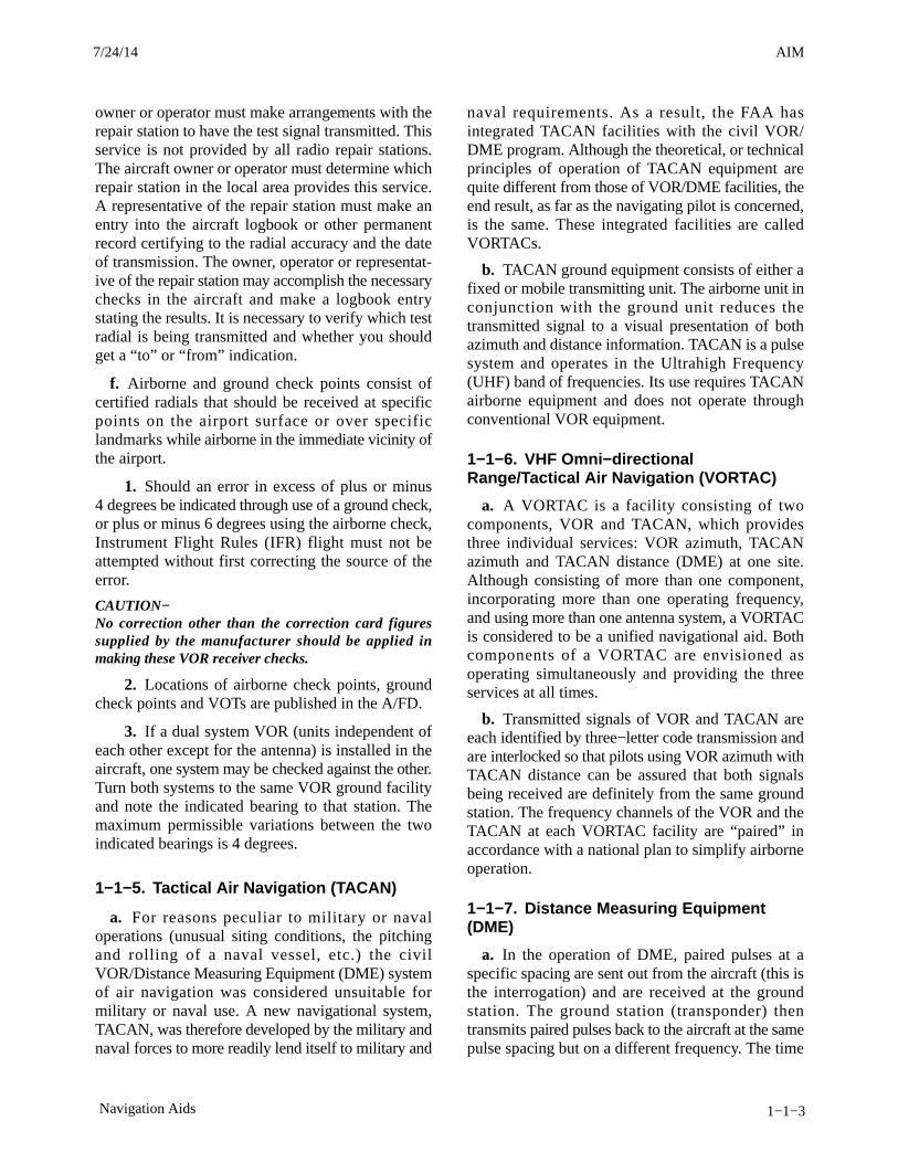
AIM4/3/14
1−1−3Navigation Aids
owner or operator must make arrangements with therepair station to have the test signal transmitted. Thisservice is not provided by all radio repair stations.The aircraft owner or operator must determine whichrepair station in the local area provides this service.A representative of the repair station must make anentry into the aircraft logbook or other permanentrecord certifying to the radial accuracy and the dateof transmission. The owner, operator or representat-ive of the repair station may accomplish the necessarychecks in the aircraft and make a logbook entrystating the results. It is necessary to verify which testradial is being transmitted and whether you shouldget a “to” or “from” indication.
f. Airborne and ground check points consist ofcertified radials that should be received at specificpoints on the airport surface or over specificlandmarks while airborne in the immediate vicinity ofthe airport.
1. Should an error in excess of plus or minus4 degrees be indicated through use of a ground check,or plus or minus 6 degrees using the airborne check,Instrument Flight Rules (IFR) flight must not beattempted without first correcting the source of theerror.
CAUTION−No correction other than the correction card figuressupplied by the manufacturer should be applied inmaking these VOR receiver checks.
2. Locations of airborne check points, groundcheck points and VOTs are published in the A/FD.
3. If a dual system VOR (units independent ofeach other except for the antenna) is installed in theaircraft, one system may be checked against the other.Turn both systems to the same VOR ground facilityand note the indicated bearing to that station. Themaximum permissible variations between the twoindicated bearings is 4 degrees.
1−1−5. Tactical Air Navigation (TACAN)
a. For reasons peculiar to military or navaloperations (unusual siting conditions, the pitchingand rolling of a naval vessel, etc.) the civilVOR/Distance Measuring Equipment (DME) systemof air navigation was considered unsuitable formilitary or naval use. A new navigational system,TACAN, was therefore developed by the military andnaval forces to more readily lend itself to military and
naval requirements. As a result, the FAA hasintegrated TACAN facilities with the civil VOR/DME program. Although the theoretical, or technicalprinciples of operation of TACAN equipment arequite different from those of VOR/DME facilities, theend result, as far as the navigating pilot is concerned,is the same. These integrated facilities are calledVORTACs.
b. TACAN ground equipment consists of either afixed or mobile transmitting unit. The airborne unit inconjunction with the ground unit reduces thetransmitted signal to a visual presentation of bothazimuth and distance information. TACAN is a pulsesystem and operates in the Ultrahigh Frequency(UHF) band of frequencies. Its use requires TACANairborne equipment and does not operate throughconventional VOR equipment.
1−1−6. VHF Omni−directionalRange/Tactical Air Navigation (VORTAC)
a. A VORTAC is a facility consisting of twocomponents, VOR and TACAN, which providesthree individual services: VOR azimuth, TACANazimuth and TACAN distance (DME) at one site.Although consisting of more than one component,incorporating more than one operating frequency,and using more than one antenna system, a VORTACis considered to be a unified navigational aid. Bothcomponents of a VORTAC are envisioned asoperating simultaneously and providing the threeservices at all times.
b. Transmitted signals of VOR and TACAN areeach identified by three−letter code transmission andare interlocked so that pilots using VOR azimuth withTACAN distance can be assured that both signalsbeing received are definitely from the same groundstation. The frequency channels of the VOR and theTACAN at each VORTAC facility are “paired” inaccordance with a national plan to simplify airborneoperation.
1−1−7. Distance Measuring Equipment(DME)
a. In the operation of DME, paired pulses at aspecific spacing are sent out from the aircraft (this isthe interrogation) and are received at the groundstation. The ground station (transponder) thentransmits paired pulses back to the aircraft at the samepulse spacing but on a different frequency. The time
7/24/14 AIM
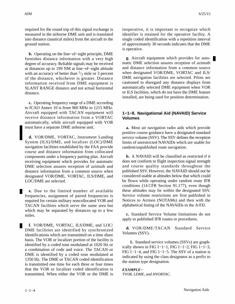
AIM 4/3/14
1−1−4 Navigation Aids
required for the round trip of this signal exchange ismeasured in the airborne DME unit and is translatedinto distance (nautical miles) from the aircraft to theground station.
b. Operating on the line−of−sight principle, DMEfurnishes distance information with a very highdegree of accuracy. Reliable signals may be receivedat distances up to 199 NM at line−of−sight altitudewith an accuracy of better than 1/2 mile or 3 percentof the distance, whichever is greater. Distanceinformation received from DME equipment isSLANT RANGE distance and not actual horizontaldistance.
c. Operating frequency range of a DME accordingto ICAO Annex 10 is from 960 MHz to 1215 MHz.Aircraft equipped with TACAN equipment willreceive distance information from a VORTACautomatically, while aircraft equipped with VORmust have a separate DME airborne unit.
d. VOR/DME, VORTAC, Instrument LandingSystem (ILS)/DME, and localizer (LOC)/DMEnavigation facilities established by the FAA providecourse and distance information from collocatedcomponents under a frequency pairing plan. Aircraftreceiving equipment which provides for automaticDME selection assures reception of azimuth anddistance information from a common source whendesignated VOR/DME, VORTAC, ILS/DME, andLOC/DME are selected.
e. Due to the limited number of availablefrequencies, assignment of paired frequencies isrequired for certain military noncollocated VOR andTACAN facilities which serve the same area butwhich may be separated by distances up to a fewmiles.
f. VOR/DME, VORTAC, ILS/DME, and LOC/DME facilities are identified by synchronizedidentifications which are transmitted on a time sharebasis. The VOR or localizer portion of the facility isidentified by a coded tone modulated at 1020 Hz ora combination of code and voice. The TACAN orDME is identified by a coded tone modulated at1350 Hz. The DME or TACAN coded identificationis transmitted one time for each three or four timesthat the VOR or localizer coded identification istransmitted. When either the VOR or the DME is
inoperative, it is important to recognize whichidentifier is retained for the operative facility. Asingle coded identification with a repetition intervalof approximately 30 seconds indicates that the DMEis operative.
g. Aircraft equipment which provides for auto-matic DME selection assures reception of azimuthand distance information from a common sourcewhen designated VOR/DME, VORTAC and ILS/DME navigation facilities are selected. Pilots arecautioned to disregard any distance displays fromautomatically selected DME equipment when VORor ILS facilities, which do not have the DME featureinstalled, are being used for position determination.
1−1−8. Navigational Aid (NAVAID) ServiceVolumes
a. Most air navigation radio aids which providepositive course guidance have a designated standardservice volume (SSV). The SSV defines the receptionlimits of unrestricted NAVAIDs which are usable forrandom/unpublished route navigation.
b. A NAVAID will be classified as restricted if itdoes not conform to flight inspection signal strengthand course quality standards throughout thepublished SSV. However, the NAVAID should not beconsidered usable at altitudes below that which couldbe flown while operating under random route IFRconditions (14 CFR Section 91.177), even thoughthese altitudes may lie within the designated SSV.Service volume restrictions are first published inNotices to Airmen (NOTAMs) and then with thealphabetical listing of the NAVAIDs in the A/FD.
c. Standard Service Volume limitations do notapply to published IFR routes or procedures.
d. VOR/DME/TACAN Standard ServiceVolumes (SSV).
1. Standard service volumes (SSVs) are graph-ically shown in FIG 1−1−1, FIG 1−1−2, FIG 1−1−3,FIG 1−1−4, and FIG 1−1−5. The SSV of a station isindicated by using the class designator as a prefix tothe station type designation.
EXAMPLE−TVOR, LDME, and HVORTAC.
3/15/077110.65R CHG 2AIM 6/25/15

AIM4/3/14
1−1−5Navigation Aids
FIG 1−1−1
Standard High Altitude Service Volume(See FIG 1−1−5 for altitudes below 1,000 feet).
60,000 ft.100 NM
130 NM
45,000 ft.
18,000 ft.
14,500 ft.
1,000 ft. 40 NM
FIG 1−1−2
Standard Low Altitude Service Volume(See FIG 1−1−5 for altitudes below 1,000 feet).
NOTE: All elevations shown are with respectto the station’s site elevation (AGL).Coverage is not available in a cone ofairspace directly above the facility.
40 NM
18,000 ft.
1,000 ft.
FIG 1−1−3
Standard Terminal Service Volume(See FIG 1−1−4 for altitudes below 1,000 feet).
25 NM
12,000 ft.
1,000 ft.
6/25/15 AIM
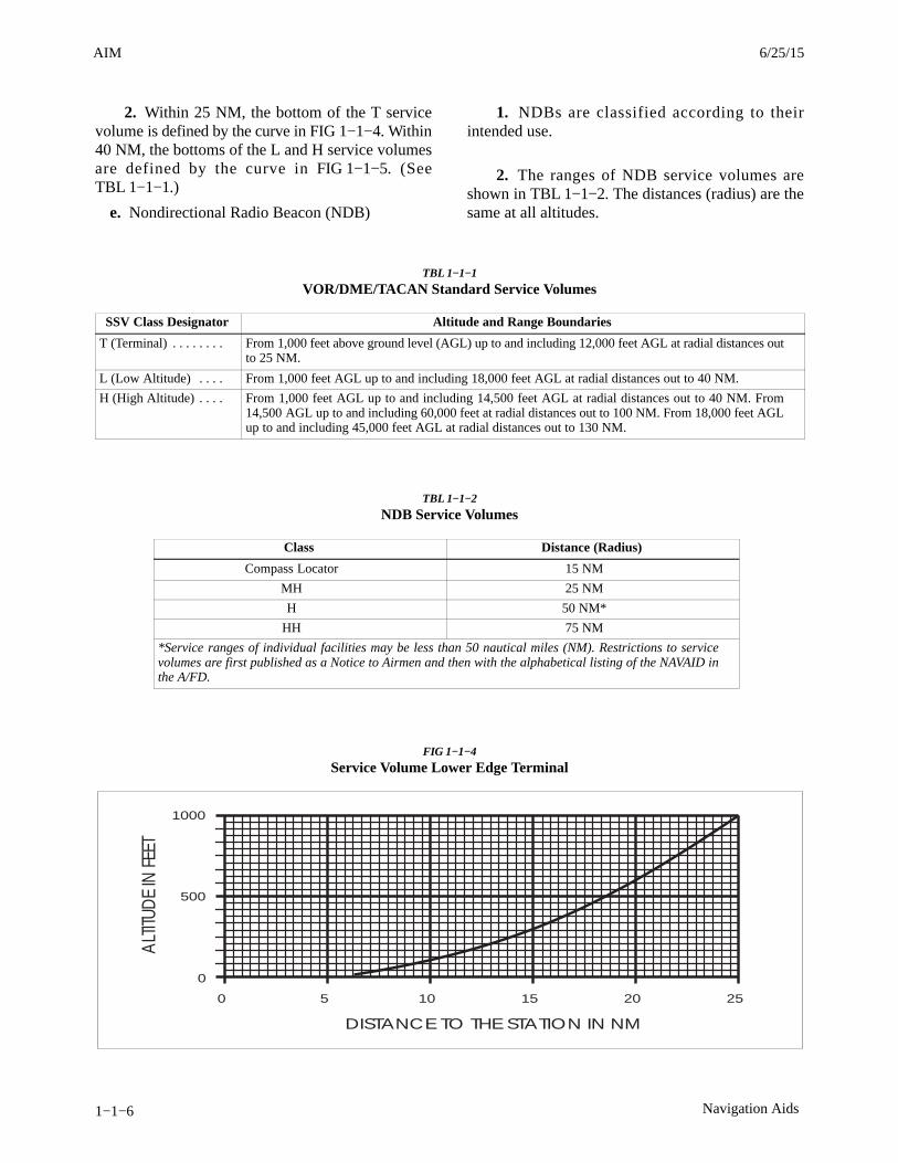
AIM 4/3/14
1−1−6 Navigation Aids
2. Within 25 NM, the bottom of the T servicevolume is defined by the curve in FIG 1−1−4. Within40 NM, the bottoms of the L and H service volumesare defined by the curve in FIG 1−1−5. (SeeTBL 1−1−1.)
e. Nondirectional Radio Beacon (NDB)
1. NDBs are classified according to theirintended use.
2. The ranges of NDB service volumes areshown in TBL 1−1−2. The distances (radius) are thesame at all altitudes.
TBL 1−1−1
VOR/DME/TACAN Standard Service Volumes
SSV Class Designator Altitude and Range Boundaries
T (Terminal) . . . . . . . . From 1,000 feet above ground level (AGL) up to and including 12,000 feet AGL at radial distances outto 25 NM.
L (Low Altitude) . . . . From 1,000 feet AGL up to and including 18,000 feet AGL at radial distances out to 40 NM.
H (High Altitude) . . . . From 1,000 feet AGL up to and including 14,500 feet AGL at radial distances out to 40 NM. From14,500 AGL up to and including 60,000 feet at radial distances out to 100 NM. From 18,000 feet AGLup to and including 45,000 feet AGL at radial distances out to 130 NM.
TBL 1−1−2
NDB Service Volumes
Class Distance (Radius)
Compass Locator 15 NM
MH 25 NM
H 50 NM*
HH 75 NM
*Service ranges of individual facilities may be less than 50 nautical miles (NM). Restrictions to servicevolumes are first published as a Notice to Airmen and then with the alphabetical listing of the NAVAID inthe A/FD.
FIG 1−1−4
Service Volume Lower Edge Terminal
1000
500
0
0 5 10 15 20 25
DISTANCE TO THE STATION IN NM
ALTIT
UDE
IN F
EET
3/15/077110.65R CHG 2AIM 6/25/15
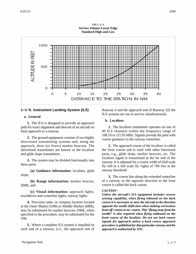
AIM4/3/14
1−1−7Navigation Aids
FIG 1−1−5
Service Volume Lower EdgeStandard High and Low
1000
500
0
0 10 20 30 40
DISTANCE TO THE STATION IN NM
ALT
ITUD
E IN
FEE
T
5 15 25 35
1−1−9. Instrument Landing System (ILS)
a. General
1. The ILS is designed to provide an approachpath for exact alignment and descent of an aircraft onfinal approach to a runway.
2. The ground equipment consists of two highlydirectional transmitting systems and, along theapproach, three (or fewer) marker beacons. Thedirectional transmitters are known as the localizerand glide slope transmitters.
3. The system may be divided functionally intothree parts:
(a) Guidance information: localizer, glideslope;
(b) Range information: marker beacon,DME; and
(c) Visual information: approach lights,touchdown and centerline lights, runway lights.
4. Precision radar, or compass locators locatedat the Outer Marker (OM) or Middle Marker (MM),may be substituted for marker beacons. DME, whenspecified in the procedure, may be substituted for theOM.
5. Where a complete ILS system is installed oneach end of a runway; (i.e., the approach end of
Runway 4 and the approach end of Runway 22) theILS systems are not in service simultaneously.
b. Localizer
1. The localizer transmitter operates on one of40 ILS channels within the frequency range of108.10 to 111.95 MHz. Signals provide the pilot withcourse guidance to the runway centerline.
2. The approach course of the localizer is calledthe front course and is used with other functionalparts, e.g., glide slope, marker beacons, etc. Thelocalizer signal is transmitted at the far end of therunway. It is adjusted for a course width of (full scalefly−left to a full scale fly−right) of 700 feet at therunway threshold.
3. The course line along the extended centerlineof a runway, in the opposite direction to the frontcourse is called the back course.
CAUTION−Unless the aircraft’s ILS equipment includes reversesensing capability, when flying inbound on the backcourse it is necessary to steer the aircraft in the directionopposite the needle deflection when making correctionsfrom off−course to on−course. This “flying away from theneedle” is also required when flying outbound on thefront course of the localizer. Do not use back coursesignals for approach unless a back course approachprocedure is published for that particular runway and theapproach is authorized by ATC.
6/25/15 AIM
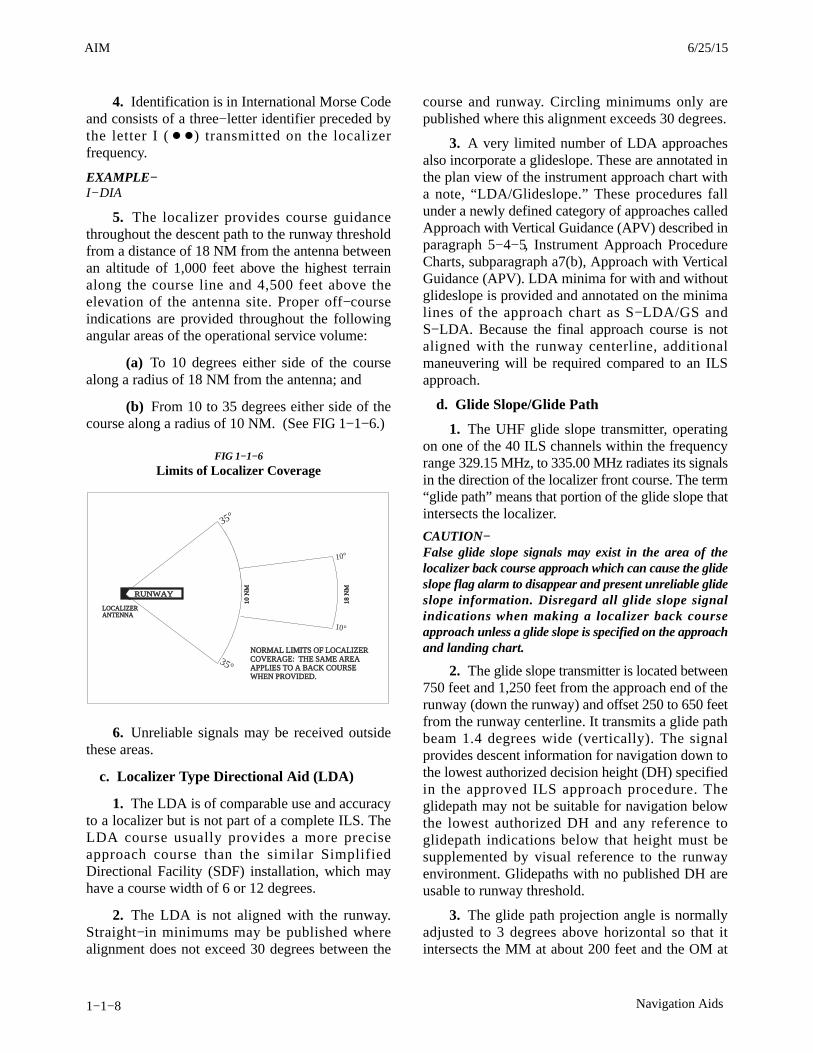
AIM 4/3/14
1−1−8 Navigation Aids
4. Identification is in International Morse Codeand consists of a three−letter identifier preceded bythe letter I ( � �) transmitted on the localizerfrequency.
EXAMPLE−I−DIA
5. The localizer provides course guidancethroughout the descent path to the runway thresholdfrom a distance of 18 NM from the antenna betweenan altitude of 1,000 feet above the highest terrainalong the course line and 4,500 feet above theelevation of the antenna site. Proper off−courseindications are provided throughout the followingangular areas of the operational service volume:
(a) To 10 degrees either side of the coursealong a radius of 18 NM from the antenna; and
(b) From 10 to 35 degrees either side of thecourse along a radius of 10 NM. (See FIG 1−1−6.)
FIG 1−1−6
Limits of Localizer Coverage
RUNWAY
LOCALIZERANTENNALOCALIZERANTENNA
10 N
M
18 N
M
NORMAL LIMITS OF LOCALIZERCOVERAGE: THE SAME AREAAPPLIES TO A BACK COURSEWHEN PROVIDED.
NORMAL LIMITS OF LOCALIZERCOVERAGE: THE SAME AREAAPPLIES TO A BACK COURSEWHEN PROVIDED.
10°
10°
35°
35°
6. Unreliable signals may be received outsidethese areas.
c. Localizer Type Directional Aid (LDA)
1. The LDA is of comparable use and accuracyto a localizer but is not part of a complete ILS. TheLDA course usually provides a more preciseapproach course than the similar SimplifiedDirectional Facility (SDF) installation, which mayhave a course width of 6 or 12 degrees.
2. The LDA is not aligned with the runway.Straight−in minimums may be published wherealignment does not exceed 30 degrees between the
course and runway. Circling minimums only arepublished where this alignment exceeds 30 degrees.
3. A very limited number of LDA approachesalso incorporate a glideslope. These are annotated inthe plan view of the instrument approach chart witha note, “LDA/Glideslope.” These procedures fallunder a newly defined category of approaches calledApproach with Vertical Guidance (APV) described inparagraph 5−4−5, Instrument Approach ProcedureCharts, subparagraph a7(b), Approach with VerticalGuidance (APV). LDA minima for with and withoutglideslope is provided and annotated on the minimalines of the approach chart as S−LDA/GS andS−LDA. Because the final approach course is notaligned with the runway centerline, additionalmaneuvering will be required compared to an ILSapproach.
d. Glide Slope/Glide Path
1. The UHF glide slope transmitter, operatingon one of the 40 ILS channels within the frequencyrange 329.15 MHz, to 335.00 MHz radiates its signalsin the direction of the localizer front course. The term“glide path” means that portion of the glide slope thatintersects the localizer.
CAUTION−False glide slope signals may exist in the area of thelocalizer back course approach which can cause the glideslope flag alarm to disappear and present unreliable glideslope information. Disregard all glide slope signalindications when making a localizer back courseapproach unless a glide slope is specified on the approachand landing chart.
2. The glide slope transmitter is located between750 feet and 1,250 feet from the approach end of therunway (down the runway) and offset 250 to 650 feetfrom the runway centerline. It transmits a glide pathbeam 1.4 degrees wide (vertically). The signalprovides descent information for navigation down tothe lowest authorized decision height (DH) specifiedin the approved ILS approach procedure. Theglidepath may not be suitable for navigation belowthe lowest authorized DH and any reference toglidepath indications below that height must besupplemented by visual reference to the runwayenvironment. Glidepaths with no published DH areusable to runway threshold.
3. The glide path projection angle is normallyadjusted to 3 degrees above horizontal so that itintersects the MM at about 200 feet and the OM at
3/15/077110.65R CHG 2AIM 6/25/15

AIM4/3/14
1−1−9Navigation Aids
about 1,400 feet above the runway elevation. Theglide slope is normally usable to the distance of10 NM. However, at some locations, the glide slopehas been certified for an extended service volumewhich exceeds 10 NM.
4. Pilots must be alert when approaching theglidepath interception. False courses and reversesensing will occur at angles considerably greater thanthe published path.
5. Make every effort to remain on the indicatedglide path.
CAUTION−Avoid flying below the glide path to assureobstacle/terrain clearance is maintained.
6. The published glide slope threshold crossingheight (TCH) DOES NOT represent the height of theactual glide path on−course indication above therunway threshold. It is used as a reference forplanning purposes which represents the height abovethe runway threshold that an aircraft’s glide slopeantenna should be, if that aircraft remains on atrajectory formed by the four−mile−to−middlemarker glidepath segment.
7. Pilots must be aware of the vertical heightbetween the aircraft’s glide slope antenna and themain gear in the landing configuration and, at the DH,plan to adjust the descent angle accordingly if thepublished TCH indicates the wheel crossing heightover the runway threshold may not be satisfactory.Tests indicate a comfortable wheel crossing height isapproximately 20 to 30 feet, depending on the type ofaircraft.
NOTE−The TCH for a runway is established based on severalfactors including the largest aircraft category thatnormally uses the runway, how airport layout effects theglide slope antenna placement, and terrain. A higher thanoptimum TCH, with the same glide path angle, may causethe aircraft to touch down further from the threshold if thetrajectory of the approach is maintained until the flare.Pilots should consider the effect of a high TCH on therunway available for stopping the aircraft.
e. Distance Measuring Equipment (DME)
1. When installed with the ILS and specified inthe approach procedure, DME may be used:
(a) In lieu of the OM;
(b) As a back course (BC) final approach fix(FAF); and
(c) To establish other fixes on the localizercourse.
2. In some cases, DME from a separate facilitymay be used within Terminal Instrument Procedures(TERPS) limitations:
(a) To provide ARC initial approach seg-ments;
(b) As a FAF for BC approaches; and
(c) As a substitute for the OM.
f. Marker Beacon
1. ILS marker beacons have a rated poweroutput of 3 watts or less and an antenna arraydesigned to produce an elliptical pattern withdimensions, at 1,000 feet above the antenna, ofapproximately 2,400 feet in width and 4,200 feet inlength. Airborne marker beacon receivers with aselective sensitivity feature should always beoperated in the “low” sensitivity position for properreception of ILS marker beacons.
2. Ordinarily, there are two marker beaconsassociated with an ILS, the OM and MM. Locationswith a Category II ILS also have an InnerMarker (IM). When an aircraft passes over a marker,the pilot will receive the indications shown inTBL 1−1−3.
(a) The OM normally indicates a position atwhich an aircraft at the appropriate altitude on thelocalizer course will intercept the ILS glide path.
(b) The MM indicates a position approxim-ately 3,500 feet from the landing threshold. This isalso the position where an aircraft on the glide pathwill be at an altitude of approximately 200 feet abovethe elevation of the touchdown zone.
(c) The IM will indicate a point at which anaircraft is at a designated decision height (DH) on theglide path between the MM and landing threshold.
TBL 1−1−3
Marker Passage Indications
Marker Code Light
OM � � � BLUE
MM � � � � AMBER
IM � � � � WHITE
BC � � � � WHITE
6/25/15 AIM

AIM 4/3/14
1−1−10 Navigation Aids
3. A back course marker normally indicates theILS back course final approach fix where approachdescent is commenced.
g. Compass Locator
1. Compass locator transmitters are oftensituated at the MM and OM sites. The transmittershave a power of less than 25 watts, a range of at least15 miles and operate between 190 and 535 kHz. Atsome locations, higher powered radio beacons, up to400 watts, are used as OM compass locators. Thesegenerally carry Transcribed Weather Broadcast(TWEB) information.
2. Compass locators transmit two letter identi-fication groups. The outer locator transmits the firsttwo letters of the localizer identification group, andthe middle locator transmits the last two letters of thelocalizer identification group.
h. ILS Frequency (See TBL 1−1−4.)
TBL 1−1−4
Frequency Pairs Allocated for ILS
Localizer MHz Glide Slope
108.10 334.70
108.15 334.55
108.3 334.10
108.35 333.95
108.5 329.90
108.55 329.75
108.7 330.50
108.75 330.35
108.9 329.30
108.95 329.15
109.1 331.40
109.15 331.25
109.3 332.00
109.35 331.85
109.50 332.60
109.55 332.45
109.70 333.20
109.75 333.05
109.90 333.80
109.95 333.65
110.1 334.40
110.15 334.25
110.3 335.00
110.35 334.85
110.5 329.60
110.55 329.45
Localizer MHz Glide Slope110.70 330.20
110.75 330.05
110.90 330.80
110.95 330.65
111.10 331.70
111.15 331.55
111.30 332.30
111.35 332.15
111.50 332.9
111.55 332.75
111.70 333.5
111.75 333.35
111.90 331.1
111.95 330.95
i. ILS Minimums
1. The lowest authorized ILS minimums, withall required ground and airborne systems componentsoperative, are:
(a) Category I. Decision Height (DH)200 feet and Runway Visual Range (RVR) 2,400 feet(with touchdown zone and centerline lighting, RVR1,800 feet), or (with Autopilot or FD or HUD, RVR1,800 feet);
(b) Special Authorization Category I.DH 150 feet and Runway Visual Range (RVR) 1,400feet, HUD to DH;
(c) Category II. DH 100 feet and RVR 1,200feet (with autoland or HUD to touchdown and notedon authorization, RVR 1,000 feet);
(d) Special Authorization Category II withReduced Lighting. DH 100 feet and RVR 1,200 feetwith autoland or HUD to touchdown and noted onauthorization (touchdown zone, centerline lighting,and ALSF−2 are not required);
(e) Category IIIa. No DH or DH below 100feet and RVR not less than 700 feet;
(f) Category IIIb. No DH or DH below 50feet and RVR less than 700 feet but not less than 150feet; and
(g) Category IIIc. No DH and no RVRlimitation.
NOTE−Special authorization and equipment required forCategories II and III.
3/15/077110.65R CHG 2AIM 6/25/15
AIM4/3/14
1−1−11Navigation Aids
j. Inoperative ILS Components
1. Inoperative localizer. When the localizerfails, an ILS approach is not authorized.
2. Inoperative glide slope. When the glideslope fails, the ILS reverts to a non−precisionlocalizer approach.
REFERENCE−See the inoperative component table in the U.S. Government TerminalProcedures Publication (TPP), for adjustments to minimums due toinoperative airborne or ground system equipment.
k. ILS Course Distortion
1. All pilots should be aware that disturbances toILS localizer and glide slope courses may occur whensurface vehicles or aircraft are operated near thelocalizer or glide slope antennas. Most ILSinstallations are subject to signal interference byeither surface vehicles, aircraft or both. ILSCRITICAL AREAS are established near eachlocalizer and glide slope antenna.
2. ATC issues control instructions to avoidinterfering operations within ILS critical areas atcontrolled airports during the hours the AirportTraffic Control Tower (ATCT) is in operation asfollows:
(a) Weather Conditions. Less than ceiling800 feet and/or visibility 2 miles.
(1) Localizer Critical Area. Except foraircraft that land, exit a runway, depart, or execute amissed approach, vehicles and aircraft are notauthorized in or over the critical area when an arrivingaircraft is inside the outer marker (OM) or the fixused in lieu of the OM. Additionally, when conditionsare less than reported ceiling 200 feet or RVR lessthan 2,000 feet, do not authorize vehicles or aircraftoperations in or over the area when an arrivingaircraft is inside the MM, or in the absence of a MM,½ mile final.
(2) Glide Slope Critical Area. Do notauthorize vehicles or aircraft operations in or over thearea when an arriving aircraft is inside the ILS outermarker (OM), or the fix used in lieu of the OM, unlessthe arriving aircraft has reported the runway in sightand is circling or side−stepping to land on anotherrunway.
(b) Weather Conditions. At or above ceil-ing 800 feet and/or visibility 2 miles.
(1) No critical area protective action isprovided under these conditions.
(2) A flight crew, under these conditions,should advise the tower that it will conduct anAUTOLAND or COUPLED approach.EXAMPLE−Denver Tower, United 1153, Request Autoland/CoupledApproach (runway)ATC replies with:United 1153, Denver Tower, Roger, Critical Areas notprotected.
3. Aircraft holding below 5,000 feet betweenthe outer marker and the airport may cause localizersignal variations for aircraft conducting the ILSapproach. Accordingly, such holding is not author-ized when weather or visibility conditions are lessthan ceiling 800 feet and/or visibility 2 miles.
4. Pilots are cautioned that vehicular traffic notsubject to ATC may cause momentary deviation toILS course or glide slope signals. Also, critical areasare not protected at uncontrolled airports or at airportswith an operating control tower when weather orvisibility conditions are above those requiringprotective measures. Aircraft conducting coupled orautoland operations should be especially alert inmonitoring automatic flight control systems. (See FIG 1−1−7.)
NOTE−Unless otherwise coordinated through Flight Standards,ILS signals to Category I runways are not flight inspectedbelow the point that is 100 feet less than the decisionaltitude (DA). Guidance signal anomalies may beencountered below this altitude.
1−1−10. Simplified Directional Facility(SDF)
a. The SDF provides a final approach coursesimilar to that of the ILS localizer. It does not provideglide slope information. A clear understanding of theILS localizer and the additional factors listed belowcompletely describe the operational characteristicsand use of the SDF.
b. The SDF transmits signals within the range of108.10 to 111.95 MHz.
c. The approach techniques and procedures usedin an SDF instrument approach are essentially thesame as those employed in executing a standardlocalizer approach except the SDF course may not be
6/25/15 AIM
AIM 4/3/14
1−1−12 Navigation Aids
aligned with the runway and the course may be wider,resulting in less precision.
d. Usable off−course indications are limited to35 degrees either side of the course centerline.Instrument indications received beyond 35 degreesshould be disregarded.
e. The SDF antenna may be offset from the runwaycenterline. Because of this, the angle of convergencebetween the final approach course and the runwaybearing should be determined by reference to theinstrument approach procedure chart. This angle isgenerally not more than 3 degrees. However, it should
be noted that inasmuch as the approach courseoriginates at the antenna site, an approach which iscontinued beyond the runway threshold will lead theaircraft to the SDF offset position rather than alongthe runway centerline.
f. The SDF signal is fixed at either 6 degrees or12 degrees as necessary to provide maximumflyability and optimum course quality.
g. Identification consists of a three−letter identifi-er transmitted in Morse Code on the SDF frequency.The appropriate instrument approach chart willindicate the identifier used at a particular airport.
3/15/077110.65R CHG 2AIM 6/25/15
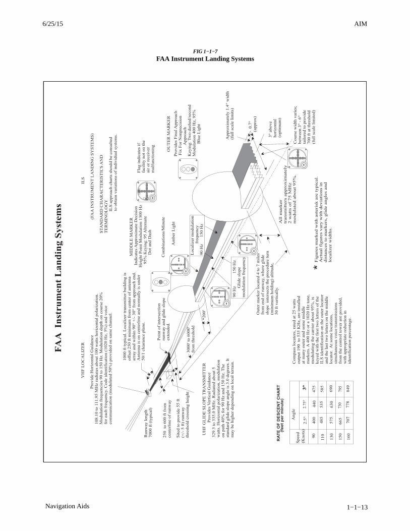
AIM4/3/14
1−1−13Navigation Aids
FIG 1−1−7
FAA Instrument Landing Systems
6/25/15 AIM
AIM 4/3/14
1−1−14 Navigation Aids
1−1−11. NAVAID Identifier Removal DuringMaintenance
During periods of routine or emergency maintenance,coded identification (or code and voice, whereapplicable) is removed from certain FAA NAVAIDs.Removal of identification serves as a warning topilots that the facility is officially off the air fortune−up or repair and may be unreliable even thoughintermittent or constant signals are received.
NOTE−During periods of maintenance VHF ranges may radiatea T−E−S−T code (- � ��� -).
NOTE−DO NOT attempt to fly a procedure that is NOTAMed outof service even if the identification is present. In certaincases, the identification may be transmitted for shortperiods as part of the testing.
1−1−12. NAVAIDs with Voice
a. Voice equipped en route radio navigational aidsare under the operational control of either a FlightService Station (FSS) or an approach control facility.The voice communication is available on somefacilities. Hazardous Inflight Weather AdvisoryService (HIWAS) broadcast capability is available onselected VOR sites throughout the conterminous U.S.and does not provide two-way voice communication.The availability of two-way voice communicationand HIWAS is indicated in the A/FD and aeronauticalcharts.
b. Unless otherwise noted on the chart, all radionavigation aids operate continuously except duringshutdowns for maintenance. Hours of operation offacilities not operating continuously are annotated oncharts and in the A/FD.
1−1−13. User Reports Requested onNAVAID or Global Navigation SatelliteSystem (GNSS) Performance orInterference
a. Users of the National Airspace System (NAS)can render valuable assistance in the early correctionof NAVAID malfunctions or GNSS problems and areencouraged to report their observations of undesir-able performance. Although NAVAIDs aremonitored by electronic detectors, adverse effects ofelectronic interference, new obstructions, or changesin terrain near the NAVAID can exist without
detection by the ground monitors. Some of thecharacteristics of malfunction or deterioratingperformance which should be reported are: erraticcourse or bearing indications; intermittent, or full,flag alarm; garbled, missing or obviously impropercoded identification; poor quality communicationsreception; or, in the case of frequency interference, anaudible hum or tone accompanying radio communic-ations or NAVAID identification. GNSS problems areoften characterized by navigation degradation orservice loss indications.
b. Reporters should identify the NAVAID (forexample, VOR) malfunction or GNSS problem,location of the aircraft (i.e., latitude, longitude orbearing/distance from a NAVAID), magnetic head-ing, altitude, date and time of the observation, typeof aircraft (make/model/call sign), and description ofthe condition observed, and the type of receivers inuse (i.e., make/model/software revision). For GNSSproblems, if possible, please note the number ofsatellites being tracked at the time of the anomaly.Reports can be made in any of the following ways:
1. Immediately, by radio communication to thecontrolling Air Route Traffic Control Center(ARTCC), Control Tower, or FSS.
2. By telephone to the nearest FAA facility.
3. For GNSS problems, by internet via the GPSAnomaly Reporting Form at http://www.faa.gov/air_traffic/nas/gps_reports/.
c. In aircraft that have more than one receiver,there are many combinations of possible interferencebetween units. This can cause either erroneousnavigation indications or, complete or partialblanking out of the communications. Pilots should befamiliar enough with the radio installation of theparticular airplanes they fly to recognize this type ofinterference.
1−1−14. LORAN
NOTE−In accordance with the 2010 DHS Appropriations Act, theU.S. Coast Guard (USCG) terminated the transmission ofall U.S. LORAN−C signals on 08 Feb 2010. The USCG alsoterminated the transmission of the Russian Americansignals on 01 Aug 2010, and the Canadian LORAN−Csignals on 03 Aug 2010. For more information, visithttp://www.navcen.uscg.gov. Operators should also notethat TSO−C60b, AIRBORNE AREA NAVIGATION
3/15/077110.65R CHG 2AIM 6/25/15
AIM4/3/14
1−1−15Navigation Aids
EQUIPMENT USING LORAN−C INPUTS, has beencanceled by the FAA.
1−1−15. Inertial Reference Unit (IRU),Inertial Navigation System (INS), andAttitude Heading Reference System (AHRS)
a. IRUs are self−contained systems comprised ofgyros and accelerometers that provide aircraftattitude (pitch, roll, and heading), position, andvelocity information in response to signals resultingfrom inertial effects on system components. Oncealigned with a known position, IRUs continuouslycalculate position and velocity. IRU positionaccuracy decays with time. This degradation isknown as “drift.”
b. INSs combine the components of an IRU withan internal navigation computer. By programming aseries of waypoints, these systems will navigate alonga predetermined track.
c. AHRSs are electronic devices that provideattitude information to aircraft systems such asweather radar and autopilot, but do not directlycompute position information.
d. Aircraft equipped with slaved compass systemsmay be susceptible to heading errors caused byexposure to magnetic field disturbances (flux fields)found in materials that are commonly located on thesurface or buried under taxiways and ramps. Thesematerials generate a magnetic flux field that can besensed by the aircraft’s compass system flux detectoror “gate”, which can cause the aircraft’s system toalign with the material’s magnetic field rather thanthe earth’s natural magnetic field. The system’serroneous heading may not self-correct. Prior to takeoff pilots should be aware that a headingmisalignment may have occurred during taxi. Pilotsare encouraged to follow the manufacturer’s or otherappropriate procedures to correct possible headingmisalignment before take off is commenced.
1−1−16. Doppler Radar
Doppler Radar is a semiautomatic self−containeddead reckoning navigation system (radar sensor pluscomputer) which is not continuously dependent oninformation derived from ground based or externalaids. The system employs radar signals to detect andmeasure ground speed and drift angle, using theaircraft compass system as its directional reference.
Doppler is less accurate than INS, however, and theuse of an external reference is required for periodicupdates if acceptable position accuracy is to beachieved on long range flights.
1−1−17. Global Positioning System (GPS)
a. System Overview
1. System Description. The Global PositioningSystem is a space-based radio navigation systemused to determine precise position anywhere in theworld. The 24 satellite constellation is designed toensure at least five satellites are always visible to auser worldwide. A minimum of four satellites isnecessary for receivers to establish an accuratethree−dimensional position. The receiver uses datafrom satellites above the mask angle (the lowestangle above the horizon at which a receiver can usea satellite). The Department of Defense (DOD) isresponsible for operating the GPS satellite constella-tion and monitors the GPS satellites to ensure properoperation. Each satellite’s orbital parameters (eph-emeris data) are sent to each satellite for broadcast aspart of the data message embedded in the GPS signal.The GPS coordinate system is the Cartesianearth−centered, earth−fixed coordinates as specifiedin the World Geodetic System 1984 (WGS−84).
2. System Availability and Reliability.
(a) The status of GPS satellites is broadcast aspart of the data message transmitted by the GPSsatellites. GPS status information is also available bymeans of the U.S. Coast Guard navigationinformation service: (703) 313−5907, Internet:http://www.navcen.uscg.gov/. Additionally, satel-lite status is available through the Notice to Airmen(NOTAM) system.
(b) GNSS operational status depends on thetype of equipment being used. For GPS−onlyequipment TSO−C129 or TSO-C196(), the opera-tional status of non−precision approach capability forflight planning purposes is provided through aprediction program that is embedded in the receiveror provided separately.
3. Receiver Autonomous Integrity Monitoring(RAIM). RAIM is the capability of a GPS receiver toperform integrity monitoring on itself by ensuringavailable satellite signals meet the integrity require-ments for a given phase of flight. Without RAIM, thepilot has no assurance of the GPS position integrity.
6/25/15 AIM
AIM 4/3/14
1−1−16 Navigation Aids
RAIM provides immediate feedback to the pilot. Thisfault detection is critical for performance-basednavigation (PBN)(see Paragraph 1−2−1, Perform-ance−Based Navigation (PBN) and Area Navigation(RNAV), for an introduction to PBN), because delaysof up to two hours can occur before an erroneoussatellite transmission is detected and corrected by thesatellite control segment.
(a) In order for RAIM to determine if asatellite is providing corrupted information, at leastone satellite, in addition to those required fornavigation, must be in view for the receiver toperform the RAIM function. RAIM requires aminimum of 5 satellites, or 4 satellites and barometricaltimeter input (baro−aiding), to detect an integrityanomaly. Baro−aiding is a method of augmenting theGPS integrity solution by using a non-satellite inputsource in lieu of the fifth satellite. Some GPSreceivers also have a RAIM capability, called faultdetection and exclusion (FDE), that excludes a failedsatellite from the position solution; GPS receiverscapable of FDE require 6 satellites or 5 satellites withbaro−aiding. This allows the GPS receiver to isolatethe corrupt satellite signal, remove it from theposition solution, and still provide an integrity-as-sured position. To ensure that baro−aiding isavailable, enter the current altimeter setting into thereceiver as described in the operating manual. Do notuse the GPS derived altitude due to the large GPSvertical errors that will make the integrity monitoringfunction invalid.
(b) There are generally two types of RAIMfault messages. The first type of message indicatesthat there are not enough satellites available toprovide RAIM integrity monitoring. The GPSnavigation solution may be acceptable, but theintegrity of the solution cannot be determined. Thesecond type indicates that the RAIM integritymonitor has detected a potential error and that thereis an inconsistency in the navigation solution for thegiven phase of flight. Without RAIM capability, thepilot has no assurance of the accuracy of the GPSposition.
4. Selective Availability. Selective Availability(SA) is a method by which the accuracy of GPS isintentionally degraded. This feature was designed todeny hostile use of precise GPS positioning data. SAwas discontinued on May 1, 2000, but many GPSreceivers are designed to assume that SA is still
active. New receivers may take advantage of thediscontinuance of SA based on the performancevalues in ICAO Annex 10.
b. Operational Use of GPS. U.S. civil operatorsmay use approved GPS equipment in oceanicairspace, certain remote areas, the National AirspaceSystem and other States as authorized (please consultthe applicable Aeronautical Information Publica-tion). Equipage other than GPS may be required forthe desired operation. GPS navigation is used for bothVisual Flight Rules (VFR) and Instrument FlightRules (IFR) operations.
1. VFR Operations
(a) GPS navigation has become an asset toVFR pilots by providing increased navigationalcapabilities and enhanced situational awareness.Although GPS has provided many benefits to theVFR pilot, care must be exercised to ensure thatsystem capabilities are not exceeded. VFR pilotsshould integrate GPS navigation with electronicnavigation (when possible), as well as pilotage anddead reckoning.
(b) GPS receivers used for VFR navigationvary from fully integrated IFR/VFR installation usedto support VFR operations to hand−held devices.Pilots must understand the limitations of the receiversprior to using in flight to avoid misusing navigationinformation. (See TBL 1−1−6.) Most receivers arenot intuitive. The pilot must learn the variouskeystrokes, knob functions, and displays that areused in the operation of the receiver. Somemanufacturers provide computer−based tutorials orsimulations of their receivers that pilots can use tobecome familiar with operating the equipment.
(c) When using GPS for VFR operations,RAIM capability, database currency, and antennalocation are critical areas of concern.
(1) RAIM Capability. VFR GPS panelmount receivers and hand−held units have no RAIMalerting capability. This prevents the pilot from beingalerted to the loss of the required number of satellitesin view, or the detection of a position error. Pilotsshould use a systematic cross−check with othernavigation techniques to verify position. Besuspicious of the GPS position if a disagreementexists between the two positions.
(2) Database Currency. Check the cur-rency of the database. Databases must be updated for
3/15/077110.65R CHG 2AIM 6/25/15
AIM4/3/14
1−1−17Navigation Aids
IFR operations and should be updated for all otheroperations. However, there is no requirement fordatabases to be updated for VFR navigation. It is notrecommended to use a moving map with an outdateddatabase in and around critical airspace. Pilots usingan outdated database should verify waypoints usingcurrent aeronautical products; for example, Airport/Facility Directory, Sectional Chart, or En RouteChart.
(3) Antenna Location. The antenna loca-tion for GPS receivers used for IFR and VFRoperations may differ. VFR antennae are typicallyplaced for convenience more than performance,while IFR installations ensure a clear view isprovided with the satellites. Antennae not providinga clear view have a greater opportunity to lose thesatellite navigational signal. This is especially truein the case of hand−held GPS receivers. Typically,suction cups are used to place the GPS antennas onthe inside of cockpit windows. While this method hasgreat utility, the antenna location is limited to thecockpit or cabin which rarely provides a clear viewof all available satellites. Consequently, signal lossesmay occur due to aircraft structure blocking satellitesignals, causing a loss of navigation capability. Theselosses, coupled with a lack of RAIM capability, couldpresent erroneous position and navigation informa-tion with no warning to the pilot. While the use of ahand−held GPS for VFR operations is not limited byregulation, modification of the aircraft, such asinstalling a panel− or yoke−mounted holder, isgoverned by 14 CFR Part 43. Consult with yourmechanic to ensure compliance with the regulationand safe installation.
(d) Do not solely rely on GPS for VFRnavigation. No design standard of accuracy orintegrity is used for a VFR GPS receiver. VFR GPSreceivers should be used in conjunction with otherforms of navigation during VFR operations to ensurea correct route of flight is maintained. Minimizehead−down time in the aircraft by being familiar withyour GPS receiver’s operation and by keeping eyesoutside scanning for traffic, terrain, and obstacles.
(e) VFR Waypoints
(1) VFR waypoints provide VFR pilotswith a supplementary tool to assist with positionawareness while navigating visually in aircraftequipped with area navigation receivers. VFRwaypoints should be used as a tool to supplement
current navigation procedures. The uses of VFRwaypoints include providing navigational aids forpilots unfamiliar with an area, waypoint definition ofexisting reporting points, enhanced navigation in andaround Class B and Class C airspace, and enhancednavigation around Special Use Airspace. VFR pilotsshould rely on appropriate and current aeronauticalcharts published specifically for visual navigation. Ifoperating in a terminal area, pilots should takeadvantage of the Terminal Area Chart available forthat area, if published. The use of VFR waypointsdoes not relieve the pilot of any responsibility tocomply with the operational requirements of 14 CFRPart 91.
(2) VFR waypoint names (for computer−entry and flight plans) consist of five lettersbeginning with the letters “VP” and are retrievablefrom navigation databases. The VFR waypointnames are not intended to be pronounceable, and theyare not for use in ATC communications. On VFRcharts, stand−alone VFR waypoints will be portrayedusing the same four−point star symbol used for IFRwaypoints. VFR waypoints collocated with visualcheck points on the chart will be identified by smallmagenta flag symbols. VFR waypoints collocatedwith visual check points will be pronounceable basedon the name of the visual check point and may be usedfor ATC communications. Each VFR waypoint namewill appear in parentheses adjacent to the geographiclocation on the chart. Latitude/longitude data for allestablished VFR waypoints may be found in theappropriate regional Airport/Facility Directory(A/FD).
(3) VFR waypoints may not be used on IFRflight plans. VFR waypoints are not recognized by theIFR system and will be rejected for IFR routingpurposes.
(4) Pilots may use the five−letter identifieras a waypoint in the route of flight section on a VFRflight plan. Pilots may use the VFR waypoints onlywhen operating under VFR conditions. The pointmay represent an intended course change or describethe planned route of flight. This VFR filing would besimilar to how a VOR would be used in a route offlight.
(5) VFR waypoints intended for use duringflight should be loaded into the receiver while on theground. Once airborne, pilots should avoid program-
6/25/15 AIM

AIM 4/3/14
1−1−18 Navigation Aids
ming routes or VFR waypoint chains into theirreceivers.
(6) Pilots should be vigilant to see andavoid other traffic when near VFR waypoints. Withthe increased use of GPS navigation and accuracy,expect increased traffic near VFR waypoints.Regardless of the class of airspace, monitor theavailable ATC frequency for traffic information onother aircraft operating in the vicinity. See Paragraph7−5−2, VFR in Congested Areas, for moreinformation.
2. IFR Use of GPS
(a) General Requirements. Authorizationto conduct any GPS operation under IFR requires:
(1) GPS navigation equipment used for IFRoperations must be approved in accordance with therequirements specified in Technical Standard Order(TSO) TSO−C129(), TSO−C196(), TSO−C145(), orTSO−C146(), and the installation must be done inaccordance with Advisory Circular AC 20−138(),Airworthiness Approval of Positioning and Naviga-tion Systems. Equipment approved in accordancewith TSO−C115a does not meet the requirements ofTSO−C129. Visual flight rules (VFR) and hand−heldGPS systems are not authorized for IFR navigation,instrument approaches, or as a principal instrumentflight reference.
(2) Aircraft using un-augmented GPS(TSO-C129() or TSO-C196()) for navigation underIFR must be equipped with an alternate approved andoperational means of navigation suitable fornavigating the proposed route of flight. (Examples ofalternate navigation equipment include VOR orDME/DME/IRU capability). Active monitoring ofalternative navigation equipment is not requiredwhen RAIM is available for integrity monitoring.Active monitoring of an alternate means ofnavigation is required when the GPS RAIMcapability is lost.
(3) Procedures must be established for usein the event that the loss of RAIM capability ispredicted to occur. In situations where RAIM ispredicted to be unavailable, the flight must rely onother approved navigation equipment, re-route towhere RAIM is available, delay departure, or cancelthe flight.
(4) The GPS operation must be conductedin accordance with the FAA−approved aircraft flightmanual (AFM) or flight manual supplement. Flightcrew members must be thoroughly familiar with theparticular GPS equipment installed in the aircraft, thereceiver operation manual, and the AFM or flightmanual supplement. Operation, receiver presenta-tion and capabilities of GPS equipment vary. Due tothese differences, operation of GPS receivers ofdifferent brands, or even models of the same brand,under IFR should not be attempted without thoroughoperational knowledge. Most receivers have abuilt−in simulator mode, which allows the pilot tobecome familiar with operation prior to attemptingoperation in the aircraft.
(5) Aircraft navigating by IFR−approvedGPS are considered to be performance−basednavigation (PBN) aircraft and have special equip-ment suffixes. File the appropriate equipment suffixin accordance with TBL 5−1−3 on the ATC flightplan. If GPS avionics become inoperative, the pilotshould advise ATC and amend the equipment suffix.
(6) Prior to any GPS IFR operation, thepilot must review appropriate NOTAMs andaeronautical information. (See GPS NOTAMs/Aero-nautical Information).
(b) Database Requirements. The onboardnavigation data must be current and appropriate forthe region of intended operation and should includethe navigation aids, waypoints, and relevant codedterminal airspace procedures for the departure,arrival, and alternate airfields.
(1) Further database guidance for terminaland en route requirements may be found in AC90-100(), U.S. Terminal and En Route AreaNavigation (RNAV) Operations.
(2) Further database guidance on RequiredNavigation Performance (RNP) instrument approachoperations, RNP terminal, and RNP en routerequirements may be found in AC 90-105(), ApprovalGuidance for RNP Operations and BarometricVertical Navigation in the U.S. National AirspaceSystem.
(3) All approach procedures to be flownmust be retrievable from the current airbornenavigation database supplied by the equipmentmanufacturer or other FAA−approved source. Thesystem must be able to retrieve the procedure by namefrom the aircraft navigation database, not just as a
3/15/077110.65R CHG 2AIM 6/25/15
AIM4/3/14
1−1−19Navigation Aids
manually entered series of waypoints. Manual entryof waypoints using latitude/longitude or place/bear-ing is not permitted for approach procedures.
(4) Prior to using a procedure or waypointretrieved from the airborne navigation database, thepilot should verify the validity of the database. Thisverification should include the following preflightand inflight steps:
[a] Preflight:
[1] Determine the date of databaseissuance, and verify that the date/time of proposeduse is before the expiration date/time.
[2] Verify that the database providerhas not published a notice limiting the use of thespecific waypoint or procedure.
[b] Inflight:
[1] Determine that the waypointsand transition names coincide with names found onthe procedure chart. Do not use waypoints which donot exactly match the spelling shown on publishedprocedure charts.
[2] Determine that the waypoints arelogical in location, in the correct order, and theirorientation to each other is as found on the procedurechart, both laterally and vertically.
NOTE−There is no specific requirement to check each waypointlatitude and longitude, type of waypoint and/or altitudeconstraint, only the general relationship of waypoints inthe procedure, or the logic of an individual waypoint’slocation.
[3] If the cursory check of procedurelogic or individual waypoint location, specified in [b]above, indicates a potential error, do not use theretrieved procedure or waypoint until a verification oflatitude and longitude, waypoint type, and altitudeconstraints indicate full conformity with thepublished data.
(5) Air carrier and commercial operatorsmust meet the appropriate provisions of theirapproved operations specifications.
[a] During domestic operations for com-merce or for hire, operators must have a secondnavigation system capable of reversion or contin-gency operations.
[b] Operators must have two independ-ent navigation systems appropriate to the route to beflown, or one system that is suitable and a second,independent backup capability that allows theoperator to proceed safely and land at a differentairport, and the aircraft must have sufficient fuel(reference 14 CFR 121.349, 125.203, 129.17, and135.165). These rules ensure the safety of theoperation by preventing a single point of failure.
NOTE−An aircraft approved for multi-sensor navigation andequipped with a single navigation system must maintain anability to navigate or proceed safely in the event that anyone component of the navigation system fails, including theflight management system (FMS). Retaining a FMS-inde-pendent VOR capability would satisfy this requirement.
[c] The requirements for a secondsystem apply to the entire set of equipment needed toachieve the navigation capability, not just theindividual components of the system such as the radionavigation receiver. For example, to use two RNAVsystems (e.g., GPS and DME/DME/IRU) to complywith the requirements, the aircraft must be equippedwith two independent radio navigation receivers andtwo independent navigation computers (e.g., flightmanagement systems (FMS)). Alternatively, tocomply with the requirements using a single RNAVsystem with an installed and operable VORcapability, the VOR capability must be independentof the FMS.
[d] To satisfy the requirement for twoindependent navigation systems, if the primarynavigation system is GPS−based, the second systemmust be independent of GPS (for example, VOR orDME/DME/IRU). This allows continued navigationin case of failure of the GPS or WAAS services.Recognizing that GPS interference and test eventsresulting in the loss of GPS services have becomemore common, the FAA requires operators conduct-ing IFR operations under 14 CFR 121.349, 125.203,129.17 and 135.65 to retain a non-GPS navigationcapability consisting of either DME/DME, IRU, orVOR for en route and terminal operations, and VORand ILS for final approach. Since this system is to beused as a reversionary capability, single equipage issufficient.
3. Oceanic, Domestic , En Route, andTerminal Area Operations
(a) Conduct GPS IFR operations in oceanicareas only when approved avionics systems are
6/25/15 AIM
AIM 4/3/14
1−1−20 Navigation Aids
installed. TSO−C196() users and TSO−C129() GPSusers authorized for Class A1, A2, B1, B2, C1, or C2operations may use GPS in place of another approvedmeans of long−range navigation, such as dual INS.(See TBL 1−1−5 and TBL 1−1−6.) Aircraft with asingle installation GPS, meeting the above specifica-tions, are authorized to operate on short oceanicroutes requiring one means of long−range navigation(reference AC 20-138(), Appendix 1).
(b) Conduct GPS domestic, en route, andterminal IFR operations only when approvedavionics systems are installed. Pilots may use GPSvia TSO−C129() authorized for Class A1, B1, B3,C1, or C3 operations GPS via TSO-C196(); orGPS/WAAS with either TSO-C145() orTSO-C146(). When using TSO-C129() orTSO-C196() receivers, the avionics necessary toreceive all of the ground−based facilities appropriatefor the route to the destination airport and anyrequired alternate airport must be installed andoperational. Ground−based facilities necessary forthese routes must be operational.
(1) GPS en route IFR operations may beconducted in Alaska outside the operational servicevolume of ground−based navigation aids when aTSO−C145() or TSO−C146() GPS/wide area aug-mentation system (WAAS) system is installed andoperating. WAAS is the U.S. version of asatellite-based augmentation system (SBAS).
[a] In Alaska, aircraft may operate onGNSS Q-routes with GPS (TSO-C129 () orTSO-C196 ()) equipment while the aircraft remainsin Air Traffic Control (ATC) radar surveillance orwith GPS/WAAS (TSO-C145 () or TSO-C146 ())which does not require ATC radar surveillance.
[b] In Alaska, aircraft may only operateon GNSS T-routes with GPS/WAAS (TSO-C145 () orTSO-C146 ()) equipment.
(2) Ground−based navigation equipmentis not required to be installed and operating for enroute IFR operations when using GPS/WAASnavigation systems. All operators should ensure thatan alternate means of navigation is available in theunlikely event the GPS/WAAS navigation systembecomes inoperative.
(3) Q-routes and T-routes outside Alaska.Q-routes require system performance currently metby GPS, GPS/WAAS, or DME/DME/IRU RNAV
systems that satisfy the criteria discussed in AC90−100(), U.S. Terminal and En Route AreaNavigation (RNAV) Operations. T-routes requireGPS or GPS/WAAS equipment.REFERENCE−AIM Paragraph 5−3−4, Airways and Route Systems
(c) GPS IFR approach/departure operationscan be conducted when approved avionics systemsare installed and the following requirements are met:
(1) The aircraft is TSO−C145() or TSO−C146() or TSO−C196() or TSO−C129() in Class A1,B1, B3, C1, or C3; and
(2) The approach/departure must be re-trievable from the current airborne navigationdatabase in the navigation computer. The systemmust be able to retrieve the procedure by name fromthe aircraft navigation database. Manual entry ofwaypoints using latitude/longitude or place/bearingis not permitted for approach procedures.
(3) The authorization to fly instrumentapproaches/departures with GPS is limited to U.S.airspace.
(4) The use of GPS in any other airspacemust be expressly authorized by the FAA Adminis-trator.
(5) GPS instrument approach/departureoperations outside the U.S. must be authorized bythe appropriate sovereign authority.
4. Departures and Instrument DepartureProcedures (DPs)
The GPS receiver must be set to terminal (±1 NM)CDI sensitivity and the navigation routes contained inthe database in order to fly published IFR charteddepartures and DPs. Terminal RAIM should beautomatically provided by the receiver. (TerminalRAIM for departure may not be available unless thewaypoints are part of the active flight plan rather thanproceeding direct to the first destination.) Certainsegments of a DP may require some manualintervention by the pilot, especially when radarvectored to a course or required to intercept a specificcourse to a waypoint. The database may not containall of the transitions or departures from all runwaysand some GPS receivers do not contain DPs in thedatabase. It is necessary that helicopter procedures beflown at 70 knots or less since helicopter departureprocedures and missed approaches use a 20:1obstacle clearance surface (OCS), which is double
1/8/15 AIM3/15/077110.65R CHG 2AIM 6/25/15

AIM4/3/14
1−1−21Navigation Aids
the fixed−wing OCS, and turning areas are based onthis speed as well.
5. GPS Instrument Approach Procedures
(a) GPS overlay approaches are designatednon−precision instrument approach procedures thatpilots are authorized to fly using GPS avionics.Localizer (LOC), localizer type directional aid(LDA), and simplified directional facility (SDF)procedures are not authorized. Overlay proceduresare identified by the “name of the procedure” and “orGPS” (e.g., VOR/DME or GPS RWY 15) in the title.Authorized procedures must be retrievable from acurrent onboard navigation database. The naviga-tion database may also enhance position orientationby displaying a map containing information onconventional NAVAID approaches. This approachinformation should not be confused with a GPSoverlay approach (see the receiver operatingmanual, AFM, or AFM Supplement for details onhow to identify these approaches in the navigationdatabase).
NOTE−Overlay approaches do not adhere to the design criteriadescribed in Paragraph 5−4−5m, Area Navigation (RNAV)Instrument Approach Charts, for stand−alone GPSapproaches. Overlay approach criteria is based on thedesign criteria used for ground−based NAVAID ap-proaches.
(b) Stand−alone approach procedures spe-cifically designed for GPS systems have replacedmany of the original overlay approaches. Allapproaches that contain “GPS” in the title (e.g.,“VOR or GPS RWY 24,” “GPS RWY 24,” or“RNAV (GPS) RWY 24”) can be flown using GPS.GPS−equipped aircraft do not need underlyingground−based NAVAIDs or associated aircraftavionics to fly the approach. Monitoring theunderlying approach with ground−based NAVAIDs issuggested when able. Existing overlay approachesmay be requested using the GPS title; for example,the VOR or GPS RWY 24 may be requested as “GPSRWY 24.” Some GPS procedures have a TerminalArrival Area (TAA) with an underlining RNAVapproach.
(c) For flight planning purposes,TSO-C129() and TSO-C196()−equipped users(GPS users) whose navigation systems have faultdetection and exclusion (FDE) capability, whoperform a preflight RAIM prediction for the
approach integrity at the airport where the RNAV(GPS) approach will be flown, and have properknowledge and any required training and/orapproval to conduct a GPS-based IAP, may filebased on a GPS−based IAP at either the destinationor the alternate airport, but not at both locations. Atthe alternate airport, pilots may plan for:
(1) Lateral navigation (LNAV) or circlingminimum descent altitude (MDA);
(2) LNAV/vertical navigation (LNAV/VNAV) DA, if equipped with and using approvedbarometric vertical navigation (baro-VNAV) equip-ment;
(3) RNP 0.3 DA on an RNAV (RNP) IAP,if they are specifically authorized users usingapproved baro-VNAV equipment and the pilot hasverified required navigation performance (RNP)availability through an approved prediction program.
(d) If the above conditions cannot be met, anyrequired alternate airport must have an approvedinstrument approach procedure other than GPS−based that is anticipated to be operational andavailable at the estimated time of arrival, and whichthe aircraft is equipped to fly.
(e) Procedures for Accomplishing GPSApproaches
(1) An RNAV (GPS) procedure may beassociated with a Terminal Arrival Area (TAA). Thebasic design of the RNAV procedure is the “T” designor a modification of the “T” (See Paragraph 5-4-5d,Terminal Arrival Area (TAA), for complete informa-tion).
(2) Pilots cleared by ATC for an RNAV(GPS) approach should fly the full approach from anInitial Approach Waypoint (IAWP) or feeder fix.Randomly joining an approach at an intermediate fixdoes not assure terrain clearance.
(3) When an approach has been loaded inthe navigation system, GPS receivers will give an“arm” annunciation 30 NM straight line distancefrom the airport/heliport reference point. Pilotsshould arm the approach mode at this time if notalready armed (some receivers arm automatically).Without arming, the receiver will not change fromen route CDI and RAIM sensitivity of ±5 NM eitherside of centerline to ±1 NM terminal sensitivity.Where the IAWP is inside this 30 mile point, a CDIsensitivity change will occur once the approach mode
6/25/15 AIM

AIM 4/3/14
1−1−22 Navigation Aids
is armed and the aircraft is inside 30 NM. Where theIAWP is beyond 30 NM from the airport/heliportreference point and the approach is armed, the CDIsensitivity will not change until the aircraft is within30 miles of the airport/heliport reference point.Feeder route obstacle clearance is predicated on thereceiver being in terminal (±1 NM) CDI sensitivityand RAIM within 30 NM of the airport/heliportreference point; therefore, the receiver should alwaysbe armed (if required) not later than the 30 NMannunciation.
(4) The pilot must be aware of what bankangle/turn rate the particular receiver uses to computeturn anticipation, and whether wind and airspeed areincluded in the receiver’s calculations. This informa-tion should be in the receiver operating manual. Overor under banking the turn onto the final approachcourse may significantly delay getting on course andmay result in high descent rates to achieve the nextsegment altitude.
(5) When within 2 NM of the FinalApproach Waypoint (FAWP) with the approachmode armed, the approach mode will switch toactive, which results in RAIM and CDI changing toapproach sensitivity. Beginning 2 NM prior to theFAWP, the full scale CDI sensitivity will smoothlychange from ±1 NM to ±0.3 NM at the FAWP. Assensitivity changes from ±1 NM to ±0.3 NMapproaching the FAWP, with the CDI not centered,the corresponding increase in CDI displacementmay give the impression that the aircraft is movingfurther away from the intended course even though itis on an acceptable intercept heading. Referencing thedigital track displacement information (cross trackerror), if it is available in the approach mode, mayhelp the pilot remain position oriented in thissituation. Being established on the final approachcourse prior to the beginning of the sensitivity changeat 2 NM will help prevent problems in interpreting theCDI display during ramp down. Therefore, request-ing or accepting vectors which will cause the aircraftto intercept the final approach course within 2 NM ofthe FAWP is not recommended.
(6) When receiving vectors to final, mostreceiver operating manuals suggest placing thereceiver in the non−sequencing mode on the FAWPand manually setting the course. This provides anextended final approach course in cases where theaircraft is vectored onto the final approach course
outside of any existing segment which is aligned withthe runway. Assigned altitudes must be maintaineduntil established on a published segment of theapproach. Required altitudes at waypoints outside theFAWP or stepdown fixes must be considered.Calculating the distance to the FAWP may berequired in order to descend at the proper location.
(7) Overriding an automatically selectedsensitivity during an approach will cancel theapproach mode annunciation. If the approach modeis not armed by 2 NM prior to the FAWP, the approachmode will not become active at 2 NM prior to theFAWP, and the equipment will flag. In theseconditions, the RAIM and CDI sensitivity will notramp down, and the pilot should not descend to MDA,but fly to the MAWP and execute a missed approach.The approach active annunciator and/or the receivershould be checked to ensure the approach mode isactive prior to the FAWP.
(8) Do not attempt to fly an approach unlessthe procedure in the onboard database is current andidentified as “GPS” on the approach chart. Thenavigation database may contain information aboutnon−overlay approach procedures that enhancesposition orientation generally by providing a map,while flying these approaches using conventionalNAVAIDs. This approach information should not beconfused with a GPS overlay approach (see thereceiver operating manual, AFM, or AFM Supple-ment for details on how to identify these proceduresin the navigation database). Flying point to point onthe approach does not assure compliance with thepublished approach procedure. The proper RAIMsensitivity will not be available and the CDIsensitivity will not automatically change to ±0.3NM. Manually setting CDI sensitivity does notautomatically change the RAIM sensitivity on somereceivers. Some existing non−precision approachprocedures cannot be coded for use with GPS and willnot be available as overlays.
(9) Pilots should pay particular attentionto the exact operation of their GPS receivers forperforming holding patterns and in the case ofoverlay approaches, operations such as procedureturns. These procedures may require manualintervention by the pilot to stop the sequencing ofwaypoints by the receiver and to resume automaticGPS navigation sequencing once the maneuver iscomplete. The same waypoint may appear in the routeof flight more than once consecutively (for example,
3/15/077110.65R CHG 2AIM 6/25/15
AIM4/3/14
1−1−23Navigation Aids
IAWP, FAWP, MAHWP on a procedure turn). Caremust be exercised to ensure that the receiver issequenced to the appropriate waypoint for thesegment of the procedure being flown, especially ifone or more fly−overs are skipped (for example,FAWP rather than IAWP if the procedure turn is notflown). The pilot may have to sequence past one ormore fly−overs of the same waypoint in order to startGPS automatic sequencing at the proper place in thesequence of waypoints.
(10) Incorrect inputs into the GPS receiverare especially critical during approaches. In somecases, an incorrect entry can cause the receiver toleave the approach mode.
(11) A fix on an overlay approach identi-fied by a DME fix will not be in the waypointsequence on the GPS receiver unless there is apublished name assigned to it. When a name isassigned, the along track distance (ATD) to thewaypoint may be zero rather than the DME stated onthe approach chart. The pilot should be alert for thison any overlay procedure where the originalapproach used DME.
(12) If a visual descent point (VDP) ispublished, it will not be included in the sequence ofwaypoints. Pilots are expected to use normal pilotingtechniques for beginning the visual descent, such asATD.
(13) Unnamed stepdown fixes in the finalapproach segment may or may not be coded in thewaypoint sequence of the aircraft’s navigationdatabase and must be identified using ATD.Stepdown fixes in the final approach segment ofRNAV (GPS) approaches are being named, inaddition to being identified by ATD. However, GPSavionics may or may not accommodate waypointsbetween the FAF and MAP. Pilots must know thecapabilities of their GPS equipment and continue toidentify stepdown fixes using ATD when necessary.
(f) Missed Approach
(1) A GPS missed approach requires pilotaction to sequence the receiver past the MAWP to themissed approach portion of the procedure. The pilotmust be thoroughly familiar with the activationprocedure for the particular GPS receiver installed inthe aircraft and must initiate appropriate action afterthe MAWP. Activating the missed approach prior tothe MAWP will cause CDI sensitivity to immediately
change to terminal (±1NM) sensitivity and thereceiver will continue to navigate to the MAWP. Thereceiver will not sequence past the MAWP. Turnsshould not begin prior to the MAWP. If the missedapproach is not activated, the GPS receiver willdisplay an extension of the inbound final approachcourse and the ATD will increase from the MAWPuntil it is manually sequenced after crossing theMAWP.
(2) Missed approach routings in which thefirst track is via a course rather than direct to the nextwaypoint require additional action by the pilot to setthe course. Being familiar with all of the inputsrequired is especially critical during this phase offlight.
(g) GPS NOTAMs/Aeronautical Informa-tion
(1) GPS satellite outages are issued asGPS NOTAMs both domestically and internation-ally. However, the effect of an outage on the intendedoperation cannot be determined unless the pilot has aRAIM availability prediction program which allowsexcluding a satellite which is predicted to be out ofservice based on the NOTAM information.
(2) The terms UNRELIABLE and MAYNOT BE AVAILABLE are used in conjunction withGPS NOTAMs. Both UNRELIABLE and MAY NOTBE AVAILABLE are advisories to pilots indicatingthe expected level of service may not be available.UNRELIABLE does not mean there is a problemwith GPS signal integrity. If GPS service is available,pilots may continue operations. If the LNAV orLNAV/VNAV service is available, pilots may use thedisplayed level of service to fly the approach. GPSoperation may be NOTAMed UNRELIABLE orMAY NOT BE AVAILABLE due to testing oranomalies. (Pilots are encouraged to report GPSanomalies, including degraded operation and/or lossof service, as soon as possible, reference paragraph1−1−13.) When GPS testing NOTAMS are publishedand testing is actually occurring, Air Traffic Controlwill advise pilots requesting or cleared for a GPS orRNAV (GPS) approach that GPS may not beavailable and request intentions. If pilots havereported GPS anomalies, Air Traffic Control willrequest the pilot’s intentions and/or clear the pilot foran alternate approach, if available and operational.
6/25/15 AIM

AIM 4/3/14
1−1−24 Navigation Aids
EXAMPLE−The following is an example of a GPS testing NOTAM: !GPS 06/001 ZAB NAV GPS (INCLUDING WAAS, GBAS,AND ADS-B) MAY NOT BE AVAILABLE WITHIN A468NM RADIUS CENTERED AT 330702N1062540W(TCS 093044) FL400-UNL DECREASING IN AREAWITH A DECREASE IN ALTITUDE DEFINED AS:425NM RADIUS AT FL250, 360NM RADIUS AT10000FT, 354NM RADIUS AT 4000FT AGL, 327NMRADIUS AT 50FT AGL. 1406070300-1406071200.
(3) Civilian pilots may obtain GPS RAIMavailability information for non−precision approachprocedures by: using a manufacturer-supplied RAIMprediction tool; or using the generic tool atwww.raimprediction.net. The FAA is developing areplacement prediction tool at www.sapt.faa.govscheduled for transition in 2014. Pilots can alsorequest GPS RAIM aeronautical information from aflight service station during preflight briefings. GPSRAIM aeronautical information can be obtained fora period of 3 hours (for example, if you are scheduledto arrive at 1215 hours, then the GPS RAIMinformation is available from 1100 to 1400 hours) ora 24−hour timeframe at a particular airport. FAAbriefers will provide RAIM information for a periodof 1 hour before to 1 hour after the ETA hour, unlessa specific timeframe is requested by the pilot. If flyinga published GPS departure, a RAIM predictionshould also be requested for the departure airport.
(4) The military provides airfield specificGPS RAIM NOTAMs for non−precision approachprocedures at military airfields. The RAIM outagesare issued as M−series NOTAMs and may be obtainedfor up to 24 hours from the time of request.
(5) Receiver manufacturers and/or data-base suppliers may supply “NOTAM” typeinformation concerning database errors. Pilotsshould check these sources, when available, to ensurethat they have the most current informationconcerning their electronic database.
(h) Receiver Autonomous Integrity Monit-oring (RAIM)
(1) RAIM outages may occur due to aninsufficient number of satellites or due to unsuitablesatellite geometry which causes the error in theposition solution to become too large. Loss of satellitereception and RAIM warnings may occur due toaircraft dynamics (changes in pitch or bank angle).Antenna location on the aircraft, satellite position
relative to the horizon, and aircraft attitude may affectreception of one or more satellites. Since the relativepositions of the satellites are constantly changing,prior experience with the airport does not guaranteereception at all times, and RAIM availability shouldalways be checked.
(2) If RAIM is not available, use anothertype of navigation and approach system, selectanother route or destination, or delay the trip untilRAIM is predicted to be available on arrival. Onlonger flights, pilots should consider rechecking theRAIM prediction for the destination during the flight.This may provide an early indication that anunscheduled satellite outage has occurred sincetakeoff.
(3) If a RAIM failure/status annunciationoccurs pr ior to the f inal approach waypoint(FAWP), the approach should not be completed sinceGPS no longer provides the required integrity. Thereceiver performs a RAIM prediction by 2 NM priorto the FAWP to ensure that RAIM is available as acondition for entering the approach mode. The pilotshould ensure the receiver has sequenced from“Armed” to “Approach” prior to the FAWP (normallyoccurs 2 NM prior). Failure to sequence may be anindication of the detection of a satellite anomaly,failure to arm the receiver (if required), or otherproblems which preclude flying the approach.
(4) If the receiver does not sequence intothe approach mode or a RAIM failure/statusannunciation occurs prior to the FAWP, the pilot mustnot initiate the approach or descend, but insteadproceed to the missed approach waypoint ( MAWP)via the FAWP, perform a missed approach, andcontact ATC as soon as practical. The GPS receivermay continue to operate after a RAIM flag/statusannunciation appears, but the navigation informationshould be considered advisory only. Refer to thereceiver operating manual for specific indicationsand instructions associated with loss of RAIM priorto the FAF.
(5) If the RAIM flag/status annunciationappears after the FAWP, the pilot should initiate aclimb and execute the missed approach. The GPSreceiver may continue to operate after a RAIMflag/status annunciation appears, but the navigationinformation should be considered advisory only.Refer to the receiver operating manual for operatingmode information during a RAIM annunciation.
3/15/077110.65R CHG 2AIM 6/25/15
AIM4/3/14
1−1−25Navigation Aids
(i) Waypoints
(1) GPS receivers navigate from onedefined point to another retrieved from the aircraft’sonboard navigational database. These points arewaypoints (5-letter pronounceable name), existingVHF intersections, DME fixes with 5−letterpronounceable names and 3-letter NAVAID IDs.Each waypoint is a geographical location defined bya latitude/longitude geographic coordinate. These5−letter waypoints, VHF intersections, 5−letterpronounceable DME fixes and 3−letter NAVAID IDsare published on various FAA aeronautical naviga-tion products (IFR Enroute Charts, VFR Charts,Terminal Procedures Publications, etc.).
(2) A Computer Navigation Fix (CNF) isalso a point defined by a latitude/longitude coordinateand is required to support Performance−BasedNavigation (PBN) operations. The GPS receiver usesCNFs in conjunction with waypoints to navigate frompoint to point. However, CNFs are not recognized byATC. ATC does not maintain CNFs in their databaseand they do not use CNFs for any air traffic controlpurpose. CNFs may or may not be charted on FAAaeronautical navigation products, are listed in thechart legends, and are for advisory purposes only.Pilots are not to use CNFs for point to pointnavigation (proceed direct), filing a flight plan, or inaircraft/ATC communications. CNFs that do appearon aeronautical charts allow pilots increasedsituational awareness by identifying points in theaircraft database route of flight with points on theaeronautical chart. CNFs are random five-letteridentifiers, not pronounceable like waypoints andplaced in parenthesis. Eventually, all CNFs will beginwith the letters “CF” followed by three consonants(for example, CFWBG). This five-letter identifierwill be found next to an “x” on enroute charts andpossibly on an approach chart. On instrumentapproach procedures (charts) in the terminalprocedures publication, CNFs may represent un-named DME fixes, beginning and ending points ofDME arcs, and sensor (ground-based signal i.e.,VOR, NDB, ILS) final approach fixes on GPSoverlay approaches. These CNFs provide the GPSwith points on the procedure that allow the overlayapproach to mirror the ground-based sensorapproach. These points should only be used by theGPS system for navigation and should not be used bypilots for any other purpose on the approach. TheCNF concept has not been adopted or recognized by
the International Civil Aviation Organization(ICAO).
(3) GPS approaches use fly−over andfly−by waypoints to join route segments on anapproach. Fly−by waypoints connect the twosegments by allowing the aircraft to turn prior to thecurrent waypoint in order to roll out on course to thenext waypoint. This is known as turn anticipation andis compensated for in the airspace and terrainclearances. The MAWP and the missed approachholding waypoint (MAHWP) are normally the onlytwo waypoints on the approach that are not fly−bywaypoints. Fly−over waypoints are used when theaircraft must overfly the waypoint prior to starting aturn to the new course. The symbol for a fly-overwaypoint is a circled waypoint. Some waypoints mayhave dual use; for example, as a fly−by waypointwhen used as an IF for a NoPT route and as a fly-overwaypoint when the same waypoint is also used as anIAF/IF hold-in-lieu of PT. When this occurs, the lessrestrictive (fly-by) symbology will be charted.Overlay approach charts and some early stand−aloneGPS approach charts may not reflect this convention.
(4) Unnamed waypoints for each airportwill be uniquely identified in the database. Althoughthe identifier may be used at different airports (forexample, RW36 will be the identifier at each airportwith a runway 36), the actual point, at each airport, isdefined by a specific latitude/longitude coordinate.
(5) The runway threshold waypoint, nor-mally the MAWP, may have a five−letter identifier(for example, SNEEZ) or be coded as RW## (forexample, RW36, RW36L). MAWPs located at therunway threshold are being changed to the RW##identifier, while MAWPs not located at the thresholdwill have a five−letter identifier. This may cause theapproach chart to differ from the aircraft databaseuntil all changes are complete. The runway thresholdwaypoint is also used as the center of the MinimumSafe Altitude (MSA) on most GPS approaches.
(j) Position Orientation.
Pilots should pay particular attention to positionorientation while using GPS. Distance and trackinformation are provided to the next activewaypoint, not to a fixed navigation aid. Receiversmay sequence when the pilot is not flying along anactive route, such as when being vectored ordeviating for weather, due to the proximity to anotherwaypoint in the route. This can be prevented by
6/25/15 AIM

AIM 4/3/14
1−1−26 Navigation Aids
placing the receiver in the non-sequencing mode.When the receiver is in the non-sequencing mode,bearing and distance are provided to the selectedwaypoint and the receiver will not sequence to thenext waypoint in the route until placed back in theauto sequence mode or the pilot selects a differentwaypoint. The pilot may have to compute the ATDto stepdown fixes and other points on overlayapproaches, due to the receiver showing ATD to thenext waypoint rather than DME to the VOR or ILSground station.
(k) Impact of Magnetic Variation on PBNSystems
(1) Differences may exist between PBNsystems and the charted magnetic courses onground−based NAVAID instrument flight procedures(IFP), enroute charts, approach charts, and StandardInstrument Departure/Standard Terminal Arrival(SID/STAR) charts. These differences are due to themagnetic variance used to calculate the magneticcourse. Every leg of an instrument procedure is firstcomputed along a desired ground track with referenceto true north. A magnetic variation correction is thenapplied to the true course in order to calculate amagnetic course for publication. The type ofprocedure will determine what magnetic variationvalue is added to the true course. A ground−basedNAVAID IFP applies the facility magnetic variationof record to the true course to get the charted magneticcourse. Magnetic courses on PBN procedures arecalculated two different ways. SID/STAR proceduresuse the airport magnetic variation of record, whileIFR enroute charts use magnetic reference bearing.PBN systems make a correction to true north byadding a magnetic variation calculated with analgorithm based on aircraft position, or by adding themagnetic variation coded in their navigationaldatabase. This may result in the PBN system and theprocedure designer using a different magneticvariation, which causes the magnetic coursedisplayed by the PBN system and the magnetic coursecharted on the IFP plate to be different. It is importantto understand, however, that PBN systems, (with theexception of VOR/DME RNAV equipment) navigateby reference to true north and display magneticcourse only for pilot reference. As such, a properlyfunctioning PBN system, containing a current andaccurate navigational database, should fly thecorrect ground track for any loaded instrumentprocedure, despite differences in displayed magnetic
course that may be attributed to magnetic variationapplication. Should significant differences betweenthe approach chart and the PBN system avionics’application of the navigation database arise, thepublished approach chart, supplemented by NOT-AMs, holds precedence.
(2) The course into a waypoint may notalways be 180 degrees different from the courseleaving the previous waypoint, due to the PBNsystem avionics’ computation of geodesic paths,distance between waypoints, and differences inmagnetic variation application. Variations indistances may also occur since PBN systemdistance−to−waypoint values are ATDs computed tothe next waypoint and the DME values published onunderlying procedures are slant−range distancesmeasured to the station. This difference increaseswith aircraft altitude and proximity to the NAVAID.
(l) GPS Familiarization
Pilots should practice GPS approaches in visualmeteorological conditions (VMC) until thoroughlyproficient with all aspects of their equipment(receiver and installation) prior to attempting flightin instrument meteorological conditions (IMC).Pilots should be proficient in the following areas:
(1) Using the receiver autonomous integ-rity monitoring (RAIM) prediction function;
(2) Inserting a DP into the flight plan,including setting terminal CDI sensitivity, if required,and the conditions under which terminal RAIM isavailable for departure;
(3) Programming the destination airport;
(4) Programming and flying the ap-proaches (especially procedure turns and arcs);
(5) Changing to another approach afterselecting an approach;
(6) Programming and flying “direct”missed approaches;
(7) Programming and flying “routed”missed approaches;
(8) Entering, flying, and exiting holdingpatterns, particularly on approaches with a secondwaypoint in the holding pattern;
(9) Programming and flying a “route” froma holding pattern;
(10) Programming and flying an approachwith radar vectors to the intermediate segment;
3/15/077110.65R CHG 2AIM 6/25/15

AIM4/3/14
1−1−27Navigation Aids
(11) Indication of the actions required forRAIM failure both before and after the FAWP; and
(12) Programming a radial and distancefrom a VOR (often used in departure instructions).
TBL 1−1−5
GPS IFR Equipment Classes/Categories
TSO−C129
EquipmentClass RAIM
Int. Nav. Sys. toProv. RAIM
Equiv.Oceanic En Route Terminal
Non−precisionApproachCapable
Class A − GPS sensor and navigation capability.
A1 yes yes yes yes yes
A2 yes yes yes yes no
Class B − GPS sensor data to an integrated navigation system (i.e., FMS, multi−sensor navigation system, etc.).
B1 yes yes yes yes yes
B2 yes yes yes yes no
B3 yes yes yes yes yes
B4 yes yes yes yes no
Class C − GPS sensor data to an integrated navigation system (as in Class B) which provides enhanced guidance to an autopilot, orflight director, to reduce flight tech. errors. Limited to 14 CFR Part 121 or equivalent criteria.
C1 yes yes yes yes yes
C2 yes yes yes yes no
C3 yes yes yes yes yes
C4 yes yes yes yes no
TBL 1−1−6
GPS Approval Required/Authorized Use
EquipmentType1
InstallationApprovalRequired
OperationalApprovalRequired
IFR En Route2
IFRTerminal2
IFR Approach3
Oceanic Remote
In Lieu ofADF and/or
DME3
Hand held4 X5
VFR Panel Mount4 X
IFR En Routeand Terminal
X X X X X
IFR Oceanic/Remote
X X X X X X
IFR En Route,Terminal, and
Approach
X X X X X X
NOTE−1To determine equipment approvals and limitations, refer to the AFM, AFM supplements, or pilot guides.2Requires verification of data for correctness if database is expired.3Requires current database or verification that the procedure has not been amended since the expiration of the database.4VFR and hand−held GPS systems are not authorized for IFR navigation, instrument approaches, or as a primary instrumentflight reference. During IFR operations they may be considered only an aid to situational awareness.5Hand−held receivers require no approval. However, any aircraft modification to support the hand−held receiver;i.e., installation of an external antenna or a permanent mounting bracket, does require approval.
6/25/15 AIM

AIM 4/3/14
1−1−28 Navigation Aids
1−1−18. Wide Area Augmentation System(WAAS)
a. General
1. The FAA developed the WAAS to improvethe accuracy, integrity and availability of GPSsignals. WAAS will allow GPS to be used, as theaviation navigation system, from takeoff throughapproach when it is complete. WAAS is a criticalcomponent of the FAA’s strategic objective for aseamless satellite navigation system for civilaviation, improving capacity and safety.
2. The International Civil Aviation Organiza-tion (ICAO) has defined Standards andRecommended Practices (SARPs) for satellite−basedaugmentation systems (SBAS) such as WAAS.Japan, India, and Europe are building similarsystems: EGNOS, the European GeostationaryNavigation Overlay System; India’s GPS andGeo-Augmented Navigation (GAGAN) system; andJapan’s Multi-functional Transport Satellite (MT-SAT)-based Satellite Augmentation System(MSAS). The merging of these systems will create anexpansive navigation capability similar to GPS, butwith greater accuracy, availability, and integrity.
3. Unlike traditional ground−based navigationaids, WAAS will cover a more extensive service area.Precisely surveyed wide−area reference stations(WRS) are linked to form the U.S. WAAS network.Signals from the GPS satellites are monitored bythese WRSs to determine satellite clock andephemeris corrections and to model the propagationeffects of the ionosphere. Each station in the networkrelays the data to a wide−area master station (WMS)where the correction information is computed. Acorrection message is prepared and uplinked to ageostationary earth orbit satellite (GEO) via a GEOuplink subsystem (GUS) which is located at theground earth station (GES). The message is thenbroadcast on the same frequency as GPS (L1,1575.42 MHz) to WAAS receivers within thebroadcast coverage area of the WAAS GEO.
4. In addition to providing the correction signal,the WAAS GEO provides an additional pseudorangemeasurement to the aircraft receiver, improving theavailability of GPS by providing, in effect, anadditional GPS satellite in view. The integrity of GPSis improved through real−time monitoring, and theaccuracy is improved by providing differential
corrections to reduce errors. The performanceimprovement is sufficient to enable approachprocedures with GPS/WAAS glide paths (verticalguidance).
5. The FAA has completed installation of 3GEO satellite links, 38 WRSs, 3 WMSs, 6 GES, andthe required terrestrial communications to supportthe WAAS network including 2 operational controlcenters. Prior to the commissioning of the WAAS forpublic use, the FAA conducted a series of test andvalidation activities. Future dual frequency opera-tions are planned.
6. GNSS navigation, including GPS andWAAS, is referenced to the WGS−84 coordinatesystem. It should only be used where the AeronauticalInformation Publications (including electronic dataand aeronautical charts) conform to WGS−84 orequivalent. Other countries’ civil aviation authoritiesmay impose additional limitations on the use of theirSBAS systems.
b. Instrument Approach Capabilities
1. A class of approach procedures whichprovide vertical guidance, but which do not meet theICAO Annex 10 requirements for precision ap-proaches has been developed to support satellitenavigation use for aviation applications worldwide.These procedures are not precision and are referred toas Approach with Vertical Guidance (APV), aredefined in ICAO Annex 6, and include approachessuch as the LNAV/VNAV and localizer performancewith vertical guidance (LPV). These approachesprovide vertical guidance, but do not meet the morestringent standards of a precision approach. Properlycertified WAAS receivers will be able to fly to LPVminima and LNAV/VNAV minima, using a WAASelectronic glide path, which eliminates the errors thatcan be introduced by using Barometric altimetry.
2. LPV minima takes advantage of the highaccuracy guidance and increased integrity providedby WAAS. This WAAS generated angular guidanceallows the use of the same TERPS approach criteriaused for ILS approaches. LPV minima may have adecision altitude as low as 200 feet height abovetouchdown with visibility minimums as low as 1/2mile, when the terrain and airport infrastructuresupport the lowest minima. LPV minima is publishedon the RNAV (GPS) approach charts (see Paragraph5−4−5, Instrument Approach Procedure Charts).
3/15/077110.65R CHG 2AIM 6/25/15
AIM4/3/14
1−1−29Navigation Aids
3. A different WAAS-based line of minima,called Localizer Performance (LP) is being added inlocations where the terrain or obstructions do notallow publication of vertically guided LPV minima.LP takes advantage of the angular lateral guidanceand smaller position errors provided by WAAS toprovide a lateral only procedure similar to an ILSLocalizer. LP procedures may provide lower minimathan a LNAV procedure due to the narrower obstacleclearance surface.
NOTE−WAAS receivers certified prior to TSO−C145b andTSO−C146b, even if they have LPV capability, do notcontain LP capability unless the receiver has beenupgraded. Receivers capable of flying LP procedures mustcontain a statement in the Aircraft Flight Manual (AFM),AFM Supplement, or Approved Supplemental FlightManual stating that the receiver has LP capability, as wellas the capability for the other WAAS and GPS approachprocedure types.
4. WAAS provides a level of service thatsupports all phases of flight, including RNAV (GPS)approaches to LNAV, LP, LNAV/VNAV, and LPVlines of minima, within system coverage. Somelocations close to the edge of the coverage may havea lower availability of vertical guidance.
c. General Requirements
1. WAAS avionics must be certified inaccordance with Technical Standard Order (TSO)TSO−C145(), Airborne Navigation Sensors Usingthe (GPS) Augmented by the Wide Area Augmenta-tion System (WAAS); or TSO−C146(), Stand−AloneAirborne Navigation Equipment Using the GlobalPositioning System (GPS) Augmented by the WideArea Augmentation System (WAAS), and installed inaccordance with Advisory Circular (AC) 20−138(),Airworthiness Approval of Positioning and Naviga-tion Systems.
2. GPS/WAAS operation must be conducted inaccordance with the FAA−approved aircraft flightmanual (AFM) and flight manual supplements. Flightmanual supplements will state the level of approachprocedure that the receiver supports. IFR approvedWAAS receivers support all GPS only operations aslong as lateral capability at the appropriate level isfunctional. WAAS monitors both GPS and WAASsatellites and provides integrity.
3. GPS/WAAS equipment is inherently capableof supporting oceanic and remote operations if the
operator obtains a fault detection and exclusion(FDE) prediction program.
4. Air carrier and commercial operators mustmeet the appropriate provisions of their approvedoperations specifications.
5. Prior to GPS/WAAS IFR operation, the pilotmust review appropriate Notices to Airmen (NOT-AMs) and aeronautical information. Thisinformation is available on request from a FlightService Station. The FAA will provide NOTAMs toadvise pilots of the status of the WAAS and level ofservice available.
(a) The term MAY NOT BE AVBL is used inconjunction with WAAS NOTAMs and indicates thatdue to ionospheric conditions, lateral guidance maystill be available when vertical guidance isunavailable. Under certain conditions, both lateraland vertical guidance may be unavailable. ThisNOTAM language is an advisory to pilots indicatingthe expected level of WAAS service (LNAV/VNAV,LPV, LP) may not be available.EXAMPLE−!FDC FDC NAV WAAS VNAV/LPV/LP MINIMA MAYNOT BE AVBL 1306111330-1306141930EST or !FDC FDC NAV WAAS VNAV/LPV MINIMA NOT AVBL,WAAS LP MINIMA MAY NOT BE AVBL1306021200-1306031200EST
WAAS MAY NOT BE AVBL NOTAMs arepredictive in nature and published for flight planningpurposes. Upon commencing an approach atlocations NOTAMed WAAS MAY NOT BE AVBL,if the WAAS avionics indicate LNAV/VNAV or LPVservice is available, then vertical guidance may beused to complete the approach using the displayedlevel of service. Should an outage occur during theapproach, reversion to LNAV minima or an alternateinstrument approach procedure may be required.When GPS testing NOTAMS are published andtesting is actually occurring, Air Traffic Control willadvise pilots requesting or cleared for a GPS orRNAV (GPS) approach that GPS may not beavailable and request intentions. If pilots havereported GPS anomalies, Air Traffic Control willrequest the pilot’s intentions and/or clear the pilot foran alternate approach, if available and operational.
(b) WAAS area-wide NOTAMs are origin-ated when WAAS assets are out of service and impactthe service area. Area−wide WAAS NOT AVAIL-ABLE (AVBL) NOTAMs indicate loss or
6/25/15 AIM

AIM 4/3/14
1−1−30 Navigation Aids
malfunction of the WAAS system. In flight, AirTraffic Control will advise pilots requesting a GPS orRNAV (GPS) approach of WAAS NOT AVBLNOTAMs if not contained in the ATIS broadcast.
EXAMPLE−For unscheduled loss of signal or service, an exampleNOTAM is: !FDC FDC NAV WAAS NOT AVBL1311160600− 1311191200EST. For scheduled loss of signal or service, an exampleNOTAM is: !FDC FDC NAV WAAS NOT AVBL1312041015- 1312082000EST.
(c) Site−specific WAAS MAY NOT BEAVBL NOTAMs indicate an expected level ofservice; for example, LNAV/VNAV, LP, or LPV maynot be available. Pilots must request site−specificWAAS NOTAMs during flight planning. In flight,Air Traffic Control will not advise pilots of WAASMAY NOT BE AVBL NOTAMs.
NOTE−Though currently unavailable, the FAA is updating itsprediction tool software to provide this site-service in thefuture.
(d) Most of North America has redundantcoverage by two or more geostationary satellites. Oneexception is the northern slope of Alaska. If there isa problem with the satellite providing coverage to thisarea, a NOTAM similar to the following example willbe issued:
EXAMPLE−!FDC 4/3406 (PAZA A0173/14) ZAN NAV WAAS SIGNALMAY NOT BE AVBL NORTH OF LINE FROM7000N150000W TO 6400N16400W. RMK WAAS USERSSHOULD CONFIRM RAIM AVAILABILITY FOR IFROPERATIONS IN THIS AREA. T-ROUTES IN THISSECTOR NOT AVBL. ANY REQUIRED ALTERNATEAIRPORT IN THIS AREA MUST HAVE AN APPROVEDINSTRUMENT APPROACH PROCEDURE OTHERTHAN GPS THAT IS ANTICIPATED TO BE OPERATION-AL AND AVAILABLE AT THE ESTIMATED TIME OFARRIVAL AND WHICH THE AIRCRAFT IS EQUIPPEDTO FLY. 1406030812-1406050812EST .
6. When GPS−testing NOTAMS are publishedand testing is actually occurring, Air Traffic Controlwill advise pilots requesting or cleared for a GPS orRNAV (GPS) approach that GPS may not beavailable and request intentions. If pilots havereported GPS anomalies, Air Traffic Control willrequest the pilot’s intentions and/or clear the pilot foran alternate approach, if available and operational.
EXAMPLE−Here is an example of a GPS testing NOTAM: !GPS 06/001 ZAB NAV GPS (INCLUDING WAAS, GBAS,AND ADS-B) MAY NOT BE AVAILABLE WITHIN A468NM RADIUS CENTERED AT 330702N1062540W(TCS 093044) FL400-UNL DECREASING IN AREAWITH A DECREASE IN ALTITUDE DEFINED AS:425NM RADIUS AT FL250, 360NM RADIUS AT10000FT, 354NM RADIUS AT 4000FT AGL, 327NMRADIUS AT 50FT AGL. 1406070300-1406071200.
7. When the approach chart is annotated withthe symbol, site−specific WAAS MAY NOT BEAVBL NOTAMs or Air Traffic advisories are notprovided for outages in WAAS LNAV/VNAV andLPV vertical service. Vertical outages may occurdaily at these locations due to being close to the edgeof WAAS system coverage. Use LNAV or circlingminima for flight planning at these locations, whetheras a destination or alternate. For flight operations atthese locations, when the WAAS avionics indicatethat LNAV/VNAV or LPV service is available, thenthe vertical guidance may be used to complete theapproach using the displayed level of service. Shouldan outage occur during the procedure, reversion toLNAV minima may be required.NOTE−Area−wide WAAS NOT AVBL NOTAMs apply to allairports in the WAAS NOT AVBL area designated in theNOTAM, including approaches at airports where anapproach chart is annotated with the symbol.
8. GPS/WAAS was developed to be used withinGEO coverage over North America without the needfor other radio navigation equipment appropriate tothe route of flight to be flown. Outside the WAAScoverage or in the event of a WAAS failure,GPS/WAAS equipment reverts to GPS−only opera-tion and satisfies the requirements for basic GPSequipment. (See paragraph 1−1−17 for theserequirements).
9. Unlike TSO−C129 avionics, which werecertified as a supplement to other means ofnavigation, WAAS avionics are evaluated withoutreliance on other navigation systems. As such,installation of WAAS avionics does not require theaircraft to have other equipment appropriate to theroute to be flown. (See paragraph 1−1−17d for moreinformation on equipment requirements.)
(a) Pilots with WAAS receivers may flightplan to use any instrument approach procedureauthorized for use with their WAAS avionics asthe planned approach at a required alternate, with
3/15/077110.65R CHG 2AIM 6/25/15
AIM4/3/14
1−1−31Navigation Aids
the following restrictions. When using WAAS atan alternate airport, flight planning must be basedon flying the RNAV (GPS) LNAV or circling minimaline, or minima on a GPS approach procedure, orconventional approach procedure with “or GPS” inthe title. Code of Federal Regulation (CFR) Part 91non−precision weather requirements must be used forplanning. Upon arrival at an alternate, when theWAAS navigation system indicates that LNAV/VNAV or LPV service is available, then verticalguidance may be used to complete the approach usingthe displayed level of service. The FAA has begunremoving the NA (Alternate Minimums NotAuthorized) symbol from select RNAV (GPS) andGPS approach procedures so they may be used byapproach approved WAAS receivers at alternateairports. Some approach procedures will still requirethe NA for other reasons, such as no weatherreporting, so it cannot be removed from allprocedures. Since every procedure must be individu-ally evaluated, removal of the NA from RNAV(GPS) and GPS procedures will take some time.
NOTE−Properly trained and approved, as required, TSO-C145()and TSO-C146() equipped users (WAAS users) with andusing approved baro-VNAV equipment may plan forLNAV/VNAV DA at an alternate airport. Specificallyauthorized WAAS users with and using approvedbaro-VNAV equipment may also plan for RNP 0.3 DA at thealternate airport as long as the pilot has verified RNPavailability through an approved prediction program.
d. Flying Procedures with WAAS
1. WAAS receivers support all basic GPSapproach functions and provide additional capabilit-ies. One of the major improvements is the ability togenerate glide path guidance, independent of groundequipment or barometric aiding. This eliminatesseveral problems such as hot and cold temperatureeffects, incorrect altimeter setting, or lack of a localaltimeter source. It also allows approach proceduresto be built without the cost of installing groundstations at each airport or runway. Some approachcertified receivers may only generate a glide pathwith performance similar to Baro−VNAV and areonly approved to fly the LNAV/VNAV line of minimaon the RNAV (GPS) approach charts. Receivers withadditional capability (including faster update ratesand smaller integrity limits) are approved to fly theLPV line of minima. The lateral integrity changesdramatically from the 0.3 NM (556 meter) limit for
GPS, LNAV, and LNAV/VNAV approach mode, to40 meters for LPV. It also provides vertical integritymonitoring, which bounds the vertical error to 50meters for LNAV/VNAV and LPVs with minima of250’ or above, and bounds the vertical error to 35meters for LPVs with minima below 250’.
2. When an approach procedure is selected andactive, the receiver will notify the pilot of the mostaccurate level of service supported by the combina-tion of the WAAS signal, the receiver, and theselected approach, using the naming conventions onthe minima lines of the selected approach procedure.For example, if an approach is published with LPVminima and the receiver is only certified forLNAV/VNAV, the equipment would indicate“LNAV/VNAV available,” even though the WAASsignal would support LPV. If flying an existingLNAV/VNAV procedure with no LPV minima, thereceiver will notify the pilot “LNAV/VNAVavailable,” even if the receiver is certified for LPVand the signal supports LPV. If the signal does notsupport vertical guidance on procedures with LPVand/or LNAV/VNAV minima, the receiver annunci-ation will read “LNAV available.” On lateral onlyprocedures with LP and LNAV minima the receiverwill indicate “LP available” or “LNAV available”based on the level of lateral service available. Oncethe level of service notification has been given, thereceiver will operate in this mode for the duration ofthe approach procedure, unless that level of servicebecomes unavailable. The receiver cannot changeback to a more accurate level of service until the nexttime an approach is activated.
NOTE−Receivers do not “fail down” to lower levels of serviceonce the approach has been activated. If only thevertical off flag appears, the pilot may elect to use theLNAV minima if the rules under which the flight isoperating allow changing the type of approach being flownafter commencing the procedure. If the lateral integritylimit is exceeded on an LP approach, a missed approachwill be necessary since there is no way to reset the lateralalarm limit while the approach is active.
3. Another additional feature of WAAS receiv-ers is the ability to exclude a bad GPS signal andcontinue operating normally. This is normallyaccomplished by the WAAS correction information.Outside WAAS coverage or when WAAS is notavailable, it is accomplished through a receiveralgorithm called FDE. In most cases this operationwill be invisible to the pilot since the receiver will
6/25/15 AIM

AIM 4/3/14
1−1−32 Navigation Aids
continue to operate with other available satellitesafter excluding the “bad” signal. This capabilityincreases the reliability of navigation.
4. Both lateral and vertical scaling for theLNAV/VNAV and LPV approach procedures aredifferent than the linear scaling of basic GPS. Whenthe complete published procedure is flown, ±1 NMlinear scaling is provided until two (2) NM prior to theFAF, where the sensitivity increases to be similar tothe angular scaling of an ILS. There are two differ-ences in the WAAS scaling and ILS: 1) on long finalapproach segments, the initial scaling will be±0.3 NM to achieve equivalent performance to GPS(and better than ILS, which is less sensitive far fromthe runway); 2) close to the runway threshold, thescaling changes to linear instead of continuing tobecome more sensitive. The width of the finalapproach course is tailored so that the total width isusually 700 feet at the runway threshold. Since theorigin point of the lateral splay for the angular portionof the final is not fixed due to antenna placement likelocalizer, the splay angle can remain fixed, making aconsistent width of final for aircraft being vectoredonto the final approach course on different lengthrunways. When the complete published procedure isnot flown, and instead the aircraft needs to capture theextended final approach course similar to ILS, thevector to final (VTF) mode is used. Under VTF, thescaling is linear at ± NM until the point where the ILSangular splay reaches a width of ±1 NM regardlessof the distance from the FAWP.
5. The WAAS scaling is also different than GPSTSO−C129() in the initial portion of the missedapproach. Two differences occur here. First, thescaling abruptly changes from the approach scaling tothe missed approach scaling, at approximately thedeparture end of the runway or when the pilot selectsmissed approach guidance rather than ramping asGPS does. Second, when the first leg of the missedapproach is a Track to Fix (TF) leg aligned within 3degrees of the inbound course, the receiver willchange to 0.3 NM linear sensitivity until the turninitiation point for the first waypoint in the missedapproach procedure, at which time it will abruptlychange to terminal (±1 NM) sensitivity. This allowsthe elimination of close in obstacles in the early partof the missed approach that may otherwise cause theDA to be raised.
6. There are two ways to select the finalapproach segment of an instrument approach. Mostreceivers use menus where the pilot selects theairport, the runway, the specific approach procedureand finally the IAF, there is also a channel numberselection method. The pilot enters a unique 5−digitnumber provided on the approach chart, and thereceiver recalls the matching final approach segmentfrom the aircraft database. A list of informationincluding the available IAFs is displayed and the pilotselects the appropriate IAF. The pilot should confirmthat the correct final approach segment was loaded bycross checking the Approach ID, which is alsoprovided on the approach chart.
7. The Along−Track Distance (ATD) during thefinal approach segment of an LNAV procedure (witha minimum descent altitude) will be to the MAWP. OnLNAV/VNAV and LPV approaches to a decisionaltitude, there is no missed approach waypoint so thealong−track distance is displayed to a point normallylocated at the runway threshold. In most cases, theMAWP for the LNAV approach is located on therunway threshold at the centerline, so these distanceswill be the same. This distance will always varyslightly from any ILS DME that may be present, sincethe ILS DME is located further down the runway.Initiation of the missed approach on the LNAV/VNAV and LPV approaches is still based on reachingthe decision altitude without any of the items listed in14 CFR Section 91.175 being visible, and must not bedelayed while waiting for the ATD to reach zero. TheWAAS receiver, unlike a GPS receiver, willautomatically sequence past the MAWP if the missedapproach procedure has been designed for RNAV.The pilot may also select missed approach prior to theMAWP; however, navigation will continue to theMAWP prior to waypoint sequencing taking place.
1−1−19. Ground Based AugmentationSystem (GBAS) Landing System (GLS)
a. General
1. The GLS provides precision navigationguidance for exact alignment and descent of aircrafton approach to a runway. It provides differentialaugmentation to the Global Navigation SatelliteSystem (GNSS).
NOTE−GBAS is the ICAO term for Local Area AugmentationSystem (LAAS).
3/15/077110.65R CHG 2AIM 6/25/15

AIM4/3/14
1−1−33Navigation Aids
2. LAAS was developed as an “ILS look−alike”system from the pilot perspective. LAAS is based onGPS signals augmented by ground equipment and hasbeen developed to provide GLS precision approachessimilar to ILS at airfields.
3. GLS provides guidance similar to ILSapproaches for the final approach segment; portionsof the GLS approach prior to and after the finalapproach segment will be based on Area Navigation(RNAV) or Required Navigation Performance(RNP).
4. The equipment consists of a GBAS GroundFacility (GGF), four reference stations, a VHF DataBroadcast (VDB) uplink antenna, and an aircraftGBAS receiver.
b. Procedure
1. Pilots will select the five digit GBAS channelnumber of the associated approach within the FlightManagement System (FMS) menu or manually selectthe five digits (system dependent). Selection of theGBAS channel number also tunes the VDB.
2. Following procedure selection, confirmationthat the correct LAAS procedure is loaded can beaccomplished by cross checking the chartedReference Path Indicator (RPI) or approach ID withthe cockpit displayed RPI or audio identification ofthe RPI with Morse Code (for some systems).
3. The pilot will fly the GLS approach using thesame techniques as an ILS, once selected andidentified.
1−1−20. Precision Approach Systems otherthan ILS and GLS
a. General
Approval and use of precision approach systemsother than ILS and GLS require the issuance ofspecial instrument approach procedures.
b. Special Instrument Approach Procedure
1. Special instrument approach proceduresmust be issued to the aircraft operator if pilot training,aircraft equipment, and/or aircraft performance isdifferent than published procedures. Special instru-ment approach procedures are not distributed forgeneral public use. These procedures are issued to anaircraft operator when the conditions for operationsapproval are satisfied.
2. General aviation operators requesting ap-proval for special procedures should contact the localFlight Standards District Office to obtain a letter ofauthorization. Air carrier operators requestingapproval for use of special procedures should contacttheir Certificate Holding District Office for authoriz-ation through their Operations Specification.
c. Transponder Landing System (TLS)
1. The TLS is designed to provide approachguidance utilizing existing airborne ILS localizer,glide slope, and transponder equipment.
2. Ground equipment consists of a transponderinterrogator, sensor arrays to detect lateral andvertical position, and ILS frequency transmitters. TheTLS detects the aircraft’s position by interrogating itstransponder. It then broadcasts ILS frequency signalsto guide the aircraft along the desired approach path.
3. TLS instrument approach procedures aredesignated Special Instrument Approach Procedures.Special aircrew training is required. TLS groundequipment provides approach guidance for only oneaircraft at a time. Even though the TLS signal isreceived using the ILS receiver, no fixed course orglidepath is generated. The concept of operation isvery similar to an air traffic controller providing radarvectors, and just as with radar vectors, the guidanceis valid only for the intended aircraft. The TLSground equipment tracks one aircraft, based on itstransponder code, and provides correction signals tocourse and glidepath based on the position of thetracked aircraft. Flying the TLS corrections com-puted for another aircraft will not provide guidancerelative to the approach; therefore, aircrews must notuse the TLS signal for navigation unless they havereceived approach clearance and completed therequired coordination with the TLS ground equip-ment operator. Navigation fixes based onconventional NAVAIDs or GPS are provided in thespecial instrument approach procedure to allowaircrews to verify the TLS guidance.
d. Special Category I Differential GPS (SCAT−I DGPS)
1. The SCAT−I DGPS is designed to provideapproach guidance by broadcasting differentialcorrection to GPS.
2. SCAT−I DGPS procedures require aircraftequipment and pilot training.
3. Ground equipment consists of GPS receiversand a VHF digital radio transmitter. The SCAT−I
6/25/15 AIM

AIM 4/3/14
1−1−34 Navigation Aids
DGPS detects the position of GPS satellites relativeto GPS receiver equipment and broadcasts differen-tial corrections over the VHF digital radio.
4. Category I Ground Based Augmentation
System (GBAS) will displace SCAT−I DGPS as thepublic use service.
REFERENCE−AIM, Para 5−4−7f, Instrument Approach Procedures.
3/15/077110.65R CHG 2AIM 6/25/15

AIM4/3/14
2−1−1Airport Lighting Aids
Chapter 2. Aeronautical Lighting and Other Airport Visual Aids
Section 1. Airport Lighting Aids
2−1−1. Approach Light Systems (ALS)
a. ALS provide the basic means to transition frominstrument flight to visual flight for landing.Operational requirements dictate the sophisticationand configuration of the approach light system for aparticular runway.
b. ALS are a configuration of signal lights startingat the landing threshold and extending into theapproach area a distance of 2400−3000 feet forprecision instrument runways and 1400−1500 feet fornonprecision instrument runways. Some systemsinclude sequenced flashing lights which appear to thepilot as a ball of light traveling towards the runway athigh speed (twice a second). (See FIG 2−1−1.)
2−1−2. Visual Glideslope Indicators
a. Visual Approach Slope Indicator (VASI)
1. VASI installations may consist of either 2, 4,6, 12, or 16 light units arranged in bars referred to asnear, middle, and far bars. Most VASI installationsconsist of 2 bars, near and far, and may consist of 2,4, or 12 light units. Some VASIs consist of three bars,near, middle, and far, which provide an additionalvisual glide path to accommodate high cockpitaircraft. This installation may consist of either 6 or16 light units. VASI installations consisting of 2, 4, or6 light units are located on one side of the runway,usually the left. Where the installation consists of12 or 16 light units, the units are located on both sidesof the runway.
2. Two−bar VASI installations provide onevisual glide path which is normally set at 3 degrees.Three−bar VASI installations provide two visualglide paths. The lower glide path is provided by thenear and middle bars and is normally set at 3 degrees
while the upper glide path, provided by the middleand far bars, is normally 1/4 degree higher. Thishigher glide path is intended for use only by highcockpit aircraft to provide a sufficient thresholdcrossing height. Although normal glide path anglesare three degrees, angles at some locations may be ashigh as 4.5 degrees to give proper obstacle clearance.Pilots of high performance aircraft are cautioned thatuse of VASI angles in excess of 3.5 degrees may causean increase in runway length required for landing androllout.
3. The basic principle of the VASI is that of colordifferentiation between red and white. Each light unitprojects a beam of light having a white segment in theupper part of the beam and red segment in the lowerpart of the beam. The light units are arranged so thatthe pilot using the VASIs during an approach will seethe combination of lights shown below.
4. The VASI is a system of lights so arranged toprovide visual descent guidance information duringthe approach to a runway. These lights are visiblefrom 3−5 miles during the day and up to 20 miles ormore at night. The visual glide path of the VASIprovides safe obstruction clearance within plus orminus 10 degrees of the extended runway centerlineand to 4 NM from the runway threshold. Descent,using the VASI, should not be initiated until theaircraft is visually aligned with the runway. Lateralcourse guidance is provided by the runway or runwaylights. In certain circumstances, the safe obstructionclearance area may be reduced by narrowing thebeam width or shortening the usable distance due tolocal limitations, or the VASI may be offset from theextended runway centerline. This will be noted in theAirport/ Facility Directory and/or applicable noticesto airmen (NOTAM).
6/25/15 AIM
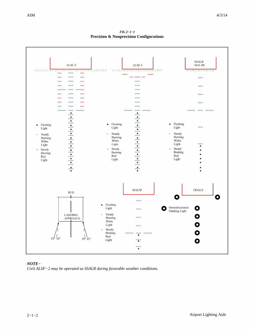
AIM 4/3/14
2−1−2 Airport Lighting Aids
FIG 2−1−1
Precision & Nonprecision Configurations
NOTE−Civil ALSF−2 may be operated as SSALR during favorable weather conditions.
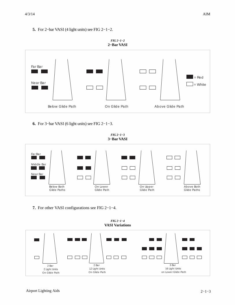
AIM4/3/14
2−1−3Airport Lighting Aids
5. For 2−bar VASI (4 light units) see FIG 2−1−2.
FIG 2−1−2
2−Bar VASI
Far Bar
= Red
= WhiteNear Bar
Below Glide Path On Glide Path Above Glide Path
6. For 3−bar VASI (6 light units) see FIG 2−1−3.
FIG 2−1−3
3−Bar VASI
Far Bar
Middle Bar
Near Bar
Below BothGlide Paths
On LowerGlide Path
On UpperGlide Path
Above BothGlide Paths
7. For other VASI configurations see FIG 2−1−4.
FIG 2−1−4
VASI Variations
2 Bar2 Light Units
On Glide Path
2 Bar12 Light UnitsOn Glide Path
3 Bar16 Light Units
on Lower Glide Path

AIM 4/3/14
2−1−4 Airport Lighting Aids
b. Precision Approach Path Indicator (PAPI).The precision approach path indicator (PAPI) useslight units similar to the VASI but are installed in asingle row of either two or four light units. Theselights are visible from about 5 miles during the dayand up to 20 miles at night. The visual glide path ofthe PAPI typically provides safe obstructionclearance within plus or minus 10 degrees of theextended runway centerline and to 4 SM from therunway threshold. Descent, using the PAPI, shouldnot be initiated until the aircraft is visually aligned
with the runway. The row of light units is normallyinstalled on the left side of the runway and the glidepath indications are as depicted. Lateral courseguidance is provided by the runway or runway lights.In certain circumstances, the safe obstructionclearance area may be reduced by narrowing thebeam width or shortening the usable distance due tolocal limitations, or the PAPI may be offset from theextended runway centerline. This will be noted in theAirport/Facility Directory and/or applicableNOTAMs. (See FIG 2−1−5.)
FIG 2−1−5
Precision Approach Path Indicator (PAPI)
Slightly High(3.2 Degrees)
White
Red
High(More Than
3,5 Degrees)
On Glide Path(3 Degrees)
Slightly Low(2.8 Degrees)
Low(Less Than
2.5 Degrees)
c. Tri−color Systems. Tri−color visual approachslope indicators normally consist of a single light unitprojecting a three−color visual approach path into thefinal approach area of the runway upon which theindicator is installed. The below glide path indicationis red, the above glide path indication is amber, and
the on glide path indication is green. These types ofindicators have a useful range of approximatelyone−half to one mile during the day and up tofive miles at night depending upon the visibilityconditions. (See FIG 2−1−6.)
FIG 2−1−6
Tri−Color Visual Approach Slope Indicator
Amber
Above Glide Path
On Glide Path
Below Glide Path
Amber
Green
Red
NOTE−1. Since the tri−color VASI consists of a single light source which could possibly be confused with other light sources, pilotsshould exercise care to properly locate and identify the light signal.
3/15/077110.65R CHG 2AIM 6/25/15
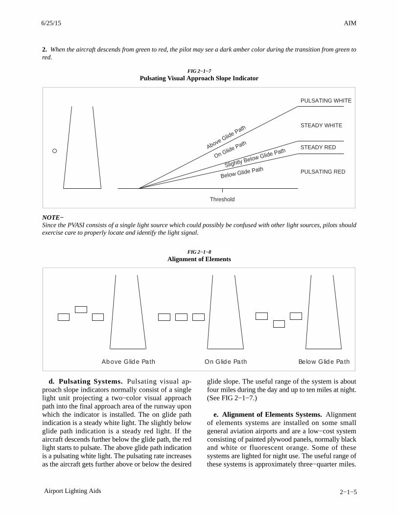
AIM4/3/14
2−1−5Airport Lighting Aids
2. When the aircraft descends from green to red, the pilot may see a dark amber color during the transition from green tored.
FIG 2−1−7
Pulsating Visual Approach Slope Indicator
Above Glide Path
On Glide Path
Below Glide PathSlightly Below Glide Path
Threshold
PULSATING WHITE
PULSATING RED
STEADY WHITE
STEADY RED
NOTE−Since the PVASI consists of a single light source which could possibly be confused with other light sources, pilots shouldexercise care to properly locate and identify the light signal.
FIG 2−1−8
Alignment of Elements
Below Glide PathOn Glide PathAbove Glide Path
d. Pulsating Systems. Pulsating visual ap-proach slope indicators normally consist of a singlelight unit projecting a two−color visual approachpath into the final approach area of the runway uponwhich the indicator is installed. The on glide pathindication is a steady white light. The slightly belowglide path indication is a steady red light. If theaircraft descends further below the glide path, the redlight starts to pulsate. The above glide path indicationis a pulsating white light. The pulsating rate increasesas the aircraft gets further above or below the desired
glide slope. The useful range of the system is aboutfour miles during the day and up to ten miles at night.(See FIG 2−1−7.)
e. Alignment of Elements Systems. Alignmentof elements systems are installed on some smallgeneral aviation airports and are a low−cost systemconsisting of painted plywood panels, normally blackand white or fluorescent orange. Some of thesesystems are lighted for night use. The useful range ofthese systems is approximately three−quarter miles.
6/25/15 AIM
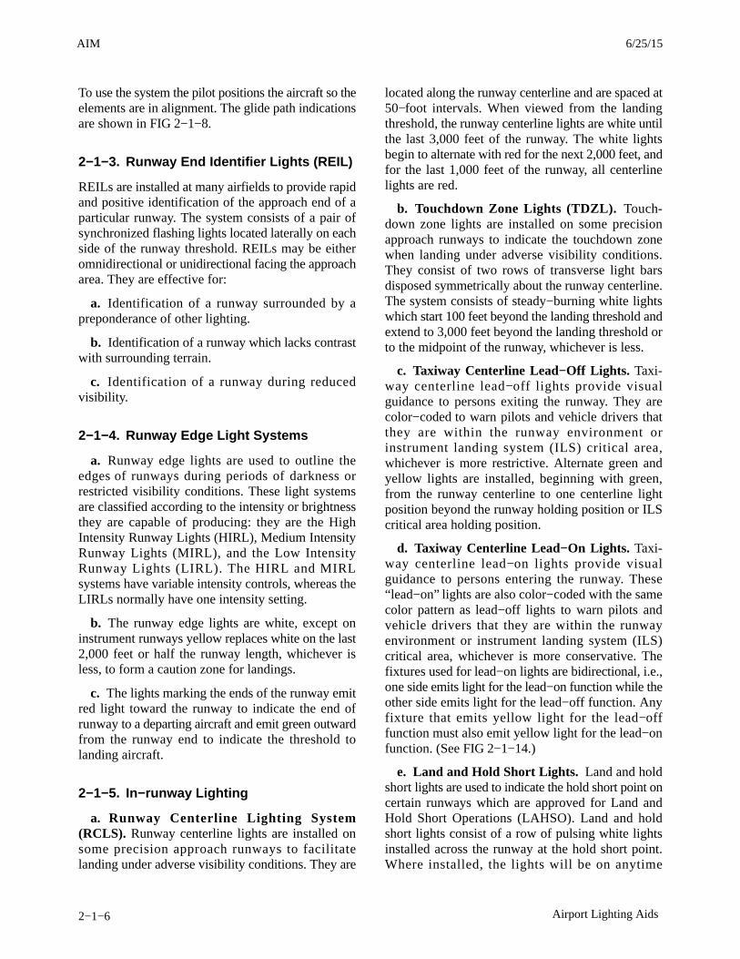
AIM 4/3/14
2−1−6 Airport Lighting Aids
To use the system the pilot positions the aircraft so theelements are in alignment. The glide path indicationsare shown in FIG 2−1−8.
2−1−3. Runway End Identifier Lights (REIL)
REILs are installed at many airfields to provide rapidand positive identification of the approach end of aparticular runway. The system consists of a pair ofsynchronized flashing lights located laterally on eachside of the runway threshold. REILs may be eitheromnidirectional or unidirectional facing the approacharea. They are effective for:
a. Identification of a runway surrounded by apreponderance of other lighting.
b. Identification of a runway which lacks contrastwith surrounding terrain.
c. Identification of a runway during reducedvisibility.
2−1−4. Runway Edge Light Systems
a. Runway edge lights are used to outline theedges of runways during periods of darkness orrestricted visibility conditions. These light systemsare classified according to the intensity or brightnessthey are capable of producing: they are the HighIntensity Runway Lights (HIRL), Medium IntensityRunway Lights (MIRL), and the Low IntensityRunway Lights (LIRL). The HIRL and MIRLsystems have variable intensity controls, whereas theLIRLs normally have one intensity setting.
b. The runway edge lights are white, except oninstrument runways yellow replaces white on the last2,000 feet or half the runway length, whichever isless, to form a caution zone for landings.
c. The lights marking the ends of the runway emitred light toward the runway to indicate the end ofrunway to a departing aircraft and emit green outwardfrom the runway end to indicate the threshold tolanding aircraft.
2−1−5. In−runway Lighting
a. Runway Centerline Lighting System(RCLS). Runway centerline lights are installed onsome precision approach runways to facilitatelanding under adverse visibility conditions. They are
located along the runway centerline and are spaced at50−foot intervals. When viewed from the landingthreshold, the runway centerline lights are white untilthe last 3,000 feet of the runway. The white lightsbegin to alternate with red for the next 2,000 feet, andfor the last 1,000 feet of the runway, all centerlinelights are red.
b. Touchdown Zone Lights (TDZL). Touch-down zone lights are installed on some precisionapproach runways to indicate the touchdown zonewhen landing under adverse visibility conditions.They consist of two rows of transverse light barsdisposed symmetrically about the runway centerline.The system consists of steady−burning white lightswhich start 100 feet beyond the landing threshold andextend to 3,000 feet beyond the landing threshold orto the midpoint of the runway, whichever is less.
c. Taxiway Centerline Lead−Off Lights. Taxi-way centerline lead−off lights provide visualguidance to persons exiting the runway. They arecolor−coded to warn pilots and vehicle drivers thatthey are within the runway environment orinstrument landing system (ILS) critical area,whichever is more restrictive. Alternate green andyellow lights are installed, beginning with green,from the runway centerline to one centerline lightposition beyond the runway holding position or ILScritical area holding position.
d. Taxiway Centerline Lead−On Lights. Taxi-way centerline lead−on lights provide visualguidance to persons entering the runway. These“lead−on” lights are also color−coded with the samecolor pattern as lead−off lights to warn pilots andvehicle drivers that they are within the runwayenvironment or instrument landing system (ILS)critical area, whichever is more conservative. Thefixtures used for lead−on lights are bidirectional, i.e.,one side emits light for the lead−on function while theother side emits light for the lead−off function. Anyfixture that emits yellow light for the lead−offfunction must also emit yellow light for the lead−onfunction. (See FIG 2−1−14.)
e. Land and Hold Short Lights. Land and holdshort lights are used to indicate the hold short point oncertain runways which are approved for Land andHold Short Operations (LAHSO). Land and holdshort lights consist of a row of pulsing white lightsinstalled across the runway at the hold short point.Where installed, the lights will be on anytime
3/15/077110.65R CHG 2AIM 6/25/15

AIM4/3/14
2−1−7Airport Lighting Aids
LAHSO is in effect. These lights will be off whenLAHSO is not in effect.
REFERENCE−AIM, Pilot Responsibilities When Conducting Land and Hold ShortOperations (LAHSO), Paragraph 4−3−11.
2−1−6. Runway Status Light (RWSL)System
a. Introduction.
RWSL is a fully automated system that providesrunway status information to pilots and surfacevehicle operators to clearly indicate when it is unsafeto enter, cross, takeoff from, or land on a runway. TheRWSL system processes information from surveil-lance systems and activates Runway Entrance Lights(REL), Takeoff Hold Lights (THL), RunwayIntersection Lights (RIL), and Final ApproachRunway Occupancy Signal (FAROS) in accordancewith the position and velocity of the detected surfacetraffic and approach traffic. REL, THL, and RIL arein-pavement light fixtures that are directly visible topilots and surface vehicle operators. FAROS alertsarriving pilots that the approaching runway isoccupied by flashing the Precision Approach PathIndicator (PAPI). FAROS may be implemented as anadd-on to the RWSL system or implemented as astand-alone system at airports without a RWSLsystem. RWSL is an independent safety enhancementthat does not substitute for or convey an ATCclearance. Clearance to enter, cross, takeoff from,land on, or operate on a runway must still be receivedfrom ATC. Although ATC has limited control overthe system, personnel do not directly use and may notbe able to view light fixture activations anddeactivations during the conduct of daily ATCoperations.
b. Runway Entrance Lights (REL): The RELsystem is composed of flush mounted, in-pavement,unidirectional light fixtures that are parallel to andfocused along the taxiway centerline and directedtoward the pilot at the hold line. An array of RELlights include the first light at the hold line followedby a series of evenly spaced lights to the runway edge;one additional light at the runway centerline is in linewith the last two lights before the runway edge (seeFIG 2−1−9 and FIG 2−1−12). When activated, thered lights indicate that there is high speed traffic onthe runway or there is an aircraft on final approachwithin the activation area.
1. REL Operating Characteristics − DepartingAircraft:
When a departing aircraft reaches a site adaptablespeed of approximately 30 knots, all taxiwayintersections with REL arrays along the runwayahead of the aircraft will illuminate (see FIG 2−1−9).As the aircraft approaches an REL equipped taxiwayintersection, the lights at that intersection extinguishapproximately 3 to 4 seconds before the aircraftreaches it. This allows controllers to apply“anticipated separation” to permit ATC to movetraffic more expeditiously without compromisingsafety. After the aircraft is declared “airborne” by thesystem, all REL lights associated with this runwaywill extinguish.
2. REL Operating Characteristics − ArrivingAircraft:
When an aircraft on final approach is approximately1 mile from the runway threshold, all sets of taxiwayREL light arrays that intersect the runway illuminate.The distance is adjustable and can be configured forspecific operations at particular airports. Lightsextinguish at each equipped taxiway intersectionapproximately 3 to 4 seconds before the aircraftreaches it to apply anticipated separation until theaircraft has slowed to approximately 80 knots (siteadjustable parameter). Below 80 knots, all arrays thatare not within 30 seconds of the aircraft’s forwardpath are extinguished. Once the arriving aircraftslows to approximately 34 knots (site adjustableparameter), it is declared to be in a taxi state, and alllights extinguish.
3. What a pilot would observe: A pilot at orapproaching the hold line to a runway will observeRELs illuminate and extinguish in reaction to anaircraft or vehicle operating on the runway, or anarriving aircraft operating less than 1 mile from therunway threshold.
4. When a pilot observes the red lights of theREL, that pilot will stop at the hold line or remainstopped. The pilot will then contact ATC forresolution if the clearance is in conflict with thelights. Should pilots note illuminated lights undercircumstances when remaining clear of the runway isimpractical for safety reasons (for example, aircraftis already on the runway), the crew should proceedaccording to their best judgment while understandingthe illuminated lights indicate the runway is unsafe to
6/25/15 AIM
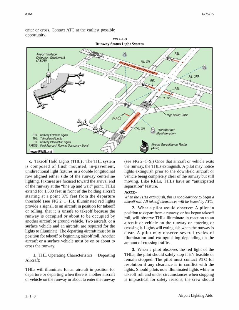
AIM 4/3/14
2−1−8 Airport Lighting Aids
enter or cross. Contact ATC at the earliest possibleopportunity.
FIG 2−1−9
Runway Status Light System
c. Takeoff Hold Lights (THL) : The THL systemis composed of flush mounted, in-pavement,unidirectional light fixtures in a double longitudinalrow aligned either side of the runway centerlinelighting. Fixtures are focused toward the arrival endof the runway at the “line up and wait” point. THLsextend for 1,500 feet in front of the holding aircraftstarting at a point 375 feet from the departurethreshold (see FIG 2−1−13). Illuminated red lightsprovide a signal, to an aircraft in position for takeoffor rolling, that it is unsafe to takeoff because therunway is occupied or about to be occupied byanother aircraft or ground vehicle. Two aircraft, or asurface vehicle and an aircraft, are required for thelights to illuminate. The departing aircraft must be inposition for takeoff or beginning takeoff roll. Anotheraircraft or a surface vehicle must be on or about tocross the runway.
1. THL Operating Characteristics − DepartingAircraft:
THLs will illuminate for an aircraft in position fordeparture or departing when there is another aircraftor vehicle on the runway or about to enter the runway
(see FIG 2−1−9.) Once that aircraft or vehicle exitsthe runway, the THLs extinguish. A pilot may noticelights extinguish prior to the downfield aircraft orvehicle being completely clear of the runway but stillmoving. Like RELs, THLs have an “anticipatedseparation” feature.
NOTE−When the THLs extinguish, this is not clearance to begin atakeoff roll. All takeoff clearances will be issued by ATC.
2. What a pilot would observe: A pilot inposition to depart from a runway, or has begun takeoffroll, will observe THLs illuminate in reaction to anaircraft or vehicle on the runway or entering orcrossing it. Lights will extinguish when the runway isclear. A pilot may observe several cycles ofillumination and extinguishing depending on theamount of crossing traffic.
3. When a pilot observes the red light of theTHLs, the pilot should safely stop if it’s feasible orremain stopped. The pilot must contact ATC forresolution if any clearance is in conflict with thelights. Should pilots note illuminated lights while intakeoff roll and under circumstances when stoppingis impractical for safety reasons, the crew should
3/15/077110.65R CHG 2AIM 6/25/15

AIM4/3/14
2−1−9Airport Lighting Aids
proceed according to their best judgment whileunderstanding the illuminated lights indicate thatcontinuing the takeoff is unsafe. Contact ATC at theearliest possible opportunity.
d. Runway Intersection Lights (RIL): The RILsystem is composed of flush mounted, in−pavement,unidirectional light fixtures in a double longitudinalrow aligned either side of the runway centerlinelighting in the same manner as THLs. Theirappearance to a pilot is similar to that of THLs.Fixtures are focused toward the arrival end of therunway, and they extend for 3,000 feet in front of anaircraft that is approaching an intersecting runway.They end at the Land and Hold Short Operation(LASHO) light bar or the hold short line for theintersecting runway.
1. RIL Operating Characteristics − DepartingAircraft:
RILs will illuminate for an aircraft departing or inposition to depart when there is high speed trafficoperating on the intersecting runway (seeFIG 2−1−9). Note that there must be an aircraft orvehicle in a position to observe the RILs for them toilluminate. Once the conflicting traffic passesthrough the intersection, the RILs extinguish.
2. RIL Operating Characteristics − ArrivingAircraft:
RILs will illuminate for an aircraft that has landed andis rolling out when there is high speed traffic on theintersecting runway that is �5 seconds of meeting atthe intersection. Once the conflicting traffic passesthrough the intersection, the RILs extinguish.
3. What a pilot would observe: A pilot departingor arriving will observe RILs illuminate in reaction tothe high speed traffic operation on the intersectingrunway. The lights will extinguish when that traffichas passed through the runway intersection.
4. Whenever a pilot observes the red light of theRIL array, the pilot will stop before the LAHSO stopbar or the hold line for the intersecting runway. If adeparting aircraft is already at high speed in thetakeoff roll when the RILs illuminate, it may beimpractical to stop for safety reasons. The crewshould safely operate according to their bestjudgment while understanding the illuminated lights
indicate that continuing the takeoff is unsafe. ContactATC at the earliest possible opportunity.
e. The Final Approach Runway Occupancy Signal(FAROS) is communicated by flashing of thePrecision Approach Path Indicator (PAPI) (see FIG2-1-9). When activated, the light fixtures of the PAPIflash or pulse to indicate to the pilot on an approachthat the runway is occupied and that it may be unsafeto land.
NOTE−FAROS is an independent automatic alerting system thatdoes not rely on ATC control or input.
1. FAROS Operating Characteristics:
If an aircraft or surface vehicle occupies a FAROSequipped runway, the PAPI(s) on that runway willflash. The glide path indication will not be affected,and the allotment of red and white PAPI lightsobserved by the pilot on approach will not change.The FAROS system will flash the PAPI when trafficenters the runway and there is an aircraft on approachand within 1.5 nautical miles of the landing threshold.
2. What a pilot would observe: A pilot onapproach to the runway will observe the PAPI flash ifthere is traffic on the runway and will notice the PAPIceases to flash when the traffic moves outside thehold short lines for the runway.
3. When a pilot observes a flashing PAPI at 500feet above ground level (AGL), the contact height,the pilot must look for and acquire the traffic on therunway. At 300 feet AGL, the pilot must contact ATCfor resolution if the FAROS indication is in conflictwith the clearance. If the PAPI continues to flash, thepilot must execute an immediate “go around” andcontact ATC at the earliest possible opportunity.
f. Pilot Actions:
1. When operating at airports with RWSL, pilotswill operate with the transponder “On” whendeparting the gate or parking area until it is shutdownupon arrival at the gate or parking area. This ensuresinteraction with the FAA surveillance systems suchas ASDE-X which provide information to the RWSLsystem.
2. Pilots must always inform the ATCT whenthey have either stopped, are verifying a landingclearance, or are executing a go-around due to RWSLor FAROS indication that are in conflict with ATCinstructions. Pilots must request clarification of thetaxi, takeoff, or landing clearance.
7/24/14 AIM6/25/15 AIM

AIM 4/3/14
2−1−10 Airport Lighting Aids
3. Never cross over illuminated red lights.Under normal circumstances, RWSL will confirm thepilot’s taxi or takeoff clearance previously issued byATC. If RWSL indicates that it is unsafe to takeofffrom, land on, cross, or enter a runway, immediatelynotify ATC of the conflict and re-confirm theclearance.
4. Do not proceed when lights have extin-guished without an ATC clearance. RWSL verifies anATC clearance; it does not substitute for an ATCclearance.
5. Never land if PAPI continues to flash.Execute a go around and notify ATC.
g. ATC Control of RWSL System:
1. Controllers can set in−pavement lights to oneof five (5) brightness levels to assure maximumconspicuity under all visibility and lighting condi-tions. REL, THL, and RIL subsystems may beindependently set.
2. System lights can be disabled should RWSLoperations impact the efficient movement of airtraffic or contribute, in the opinion of the assignedATC Manager, to unsafe operations. REL, THL, RIL,and FAROS light fixtures may be disabled separately.Disabling of the FAROS subsystem does notextinguish PAPI lights or impact its glide pathfunction. Whenever the system or a component isdisabled, a NOTAM must be issued, and the
Automatic Terminal Information System (ATIS)must be updated.
2−1−7. Stand-Alone Final ApproachRunway Occupancy Signal (FAROS)
a. Introduction:
The stand-alone FAROS system is a fully automatedsystem that provides runway occupancy status topilots on final approach to indicate whether it may beunsafe to land. When an aircraft or vehicle is detectedon the runway, the Precision Approach Path Indicator(PAPI) light fixtures flash as a signal to indicate thatthe runway is occupied and that it may be unsafe toland. The stand-alone FAROS system is activated bylocalized or comprehensive sensors detecting aircraftor ground vehicles occupying activation zones.
The stand-alone FAROS system monitors specificareas of the runway, called activation zones, todetermine the presence of aircraft or ground vehiclesin the zone (see FIG 2−1−10). These activation zonesare defined as areas on the runway that are frequentlyoccupied by ground traffic during normal airportoperations and could present a hazard to landingaircraft. Activation zones may include the full-lengthdeparture position, the midfield departure position, afrequently crossed intersection, or the entire runway.
Pilots can refer to the airport specific FAROS pilotinformation sheet for activation zone configuration.
FIG 2−1−10
FAROS Activation Zones
Clearance to land on a runway must be issued by AirTraffic Control (ATC). ATC personnel have limited
control over the system and may not be able to viewthe FAROS signal.
3/15/077110.65R CHG 2AIM 6/25/15

AIM4/3/14
4−1−11Services Available to Pilots
EXAMPLE−Low altitude alert Cessna Three Four Juliet, check youraltitude immediately. And if the aircraft is not yet on finalapproach, the MVA (MEA/MIA/MOCA) in your area is sixthousand.
2. Terminal Automated Radar Terminal System(ARTS) IIIA, Common ARTS (to include ARTS IIIEand ARTS IIE) (CARTS), Micro En RouteAutomated Radar Tracking System (MEARTS), andStandard Terminal Automation Replacement System(STARS) facilities have an automated functionwhich, if operating, alerts controllers when a trackedMode C equipped aircraft under their control is belowor is predicted to be below a predetermined minimumsafe altitude. This function, called Minimum SafeAltitude Warning (MSAW), is designed solely as acontroller aid in detecting potentially unsafe aircraftproximity to terrain/obstructions. The ARTS IIIA,CARTS, MEARTS, and STARS facility will, whenMSAW is operating, provide MSAW monitoring forall aircraft with an operating Mode C altitudeencoding transponder that are tracked by the systemand are:
(a) Operating on an IFR flight plan; or
(b) Operating VFR and have requestedMSAW monitoring.
3. Terminal AN/TPX−42A (number beacondecoder system) facilities have an automatedfunction called Low Altitude Alert System (LAAS).Although not as sophisticated as MSAW, LAASalerts the controller when a Mode C transponderequipped aircraft operating on an IFR flight plan isbelow a predetermined minimum safe altitude.
NOTE−Pilots operating VFR may request MSAW or LAASmonitoring if their aircraft are equipped with Mode Ctransponders.
EXAMPLE−Apache Three Three Papa request MSAW/LAAS.
b. Aircraft Conflict Alert.
1. Controllers will immediately issue an alert tothe pilot of an aircraft under their control if they areaware of another aircraft which is not under theircontrol, at an altitude which, in the controller’sjudgment, places both aircraft in unsafe proximity toeach other. With the alert, when feasible, thecontroller will offer the pilot the position of the trafficif time permits and an alternate course(s) of action.
Any alternate course(s) of action the controller mayrecommend to the pilot will be predicated only onother traffic being worked by the controller.
EXAMPLE−American Three, traffic alert, (position of traffic, if timepermits), advise you turn right/left heading (degrees)and/or climb/descend to (altitude) immediately.
4−1−17. Radar Assistance to VFR Aircraft
a. Radar equipped FAA ATC facilities provideradar assistance and navigation service (vectors) toVFR aircraft provided the aircraft can communicatewith the facility, are within radar coverage, and can beradar identified.
b. Pilots should clearly understand that authoriza-tion to proceed in accordance with such radarnavigational assistance does not constitute authoriza-tion for the pilot to violate CFRs. In effect, assistanceprovided is on the basis that navigational guidanceinformation issued is advisory in nature and the job offlying the aircraft safely, remains with the pilot.
c. In many cases, controllers will be unable todetermine if flight into instrument conditions willresult from their instructions. To avoid possiblehazards resulting from being vectored into IFRconditions, pilots should keep controllers advised ofthe weather conditions in which they are operatingand along the course ahead.
d. Radar navigation assistance (vectors) may beinitiated by the controller when one of the followingconditions exist:
1. The controller suggests the vector and thepilot concurs.
2. A special program has been established andvectoring service has been advertised.
3. In the controller’s judgment the vector isnecessary for air safety.
e. Radar navigation assistance (vectors) and otherradar derived information may be provided inresponse to pilot requests. Many factors, such aslimitations of radar, volume of traffic, communica-tions frequency, congestion, and controller workloadcould prevent the controller from providing it.Controllers have complete discretion for determiningif they are able to provide the service in a particularcase. Their decision not to provide the service in aparticular case is not subject to question.
6/25/15 AIM
AIM 4/3/14
4−1−12 Services Available to Pilots
4−1−18. Terminal Radar Services for VFRAircraft
a. Basic Radar Service:
1. In addition to the use of radar for the controlof IFR aircraft, all commissioned radar facilitiesprovide the following basic radar services for VFRaircraft:
(a) Safety alerts.
(b) Traffic advisories.
(c) Limited radar vectoring (on a workloadpermitting basis).
(d) Sequencing at locations where proce-dures have been established for this purpose and/orwhen covered by a Letter of Agreement.
NOTE−When the stage services were developed, two basic radarservices (traffic advisories and limited vectoring) wereidentified as “Stage I.” This definition became unneces-sary and the term “Stage I” was eliminated from use. Theterm “Stage II” has been eliminated in conjunction withthe airspace reclassification, and sequencing services tolocations with local procedures and/or letters of agreementto provide this service have been included in basic servicesto VFR aircraft. These basic services will still be providedby all terminal radar facilities whether they includeClass B, Class C, Class D or Class E airspace. “Stage III”services have been replaced with “Class B” and “TRSA”service where applicable.
2. Vectoring service may be provided whenrequested by the pilot or with pilot concurrence whensuggested by ATC.
3. Pilots of arriving aircraft should contactapproach control on the publicized frequency andgive their position, altitude, aircraft call sign, typeaircraft, radar beacon code (if transponder equipped),destination, and request traffic information.
4. Approach control will issue wind andrunway, except when the pilot states “have numbers”or this information is contained in the ATIS broadcastand the pilot states that the current ATIS informationhas been received. Traffic information is provided ona workload permitting basis. Approach control willspecify the time or place at which the pilot is tocontact the tower on local control frequency forfurther landing information. Radar service isautomatically terminated and the aircraft need not beadvised of termination when an arriving VFR aircraft
receiving radar services to a tower−controlled airportwhere basic radar service is provided has landed, orto all other airports, is instructed to change to toweror advisory frequency. (See FAA Order JO 7110.65,Air Traffic Control, paragraph 5−1−13, RadarService Termination.)
5. Sequencing for VFR aircraft is available atcertain terminal locations (see locations listed in theAirport/Facility Directory). The purpose of theservice is to adjust the flow of arriving VFR and IFRaircraft into the traffic pattern in a safe and orderlymanner and to provide radar traffic information todeparting VFR aircraft. Pilot participation is urgedbut is not mandatory. Traffic information is providedon a workload permitting basis. Standard radarseparation between VFR or between VFR and IFRaircraft is not provided.
(a) Pilots of arriving VFR aircraft shouldinitiate radio contact on the publicized frequencywith approach control when approximately 25 milesfrom the airport at which sequencing services arebeing provided. On initial contact by VFR aircraft,approach control will assume that sequencing serviceis requested. After radar contact is established, thepilot may use pilot navigation to enter the trafficpattern or, depending on traffic conditions, approachcontrol may provide the pilot with routings or vectorsnecessary for proper sequencing with other partici-pating VFR and IFR traffic en route to the airport.When a flight is positioned behind a precedingaircraft and the pilot reports having that aircraft insight, the pilot will be instructed to follow thepreceding aircraft. THE ATC INSTRUCTION TOFOLLOW THE PRECEDING AIRCRAFT DOESNOT AUTHORIZE THE PILOT TO COMPLYWITH ANY ATC CLEARANCE OR INSTRUC-TION ISSUED TO THE PRECEDING AIRCRAFT.If other “nonparticipating” or “local” aircraft are inthe traffic pattern, the tower will issue a landingsequence. If an arriving aircraft does not want radarservice, the pilot should state “NEGATIVE RADARSERVICE” or make a similar comment, on initialcontact with approach control.
(b) Pilots of departing VFR aircraft areencouraged to request radar traffic information bynotifying ground control on initial contact with theirrequest and proposed direction of flight.

AIM4/3/14
4−3−1Airport Operations
Section 3. Airport Operations
4−3−1. General
Increased traffic congestion, aircraft in climb anddescent attitudes, and pilot preoccupation withcockpit duties are some factors that increase thehazardous accident potential near the airport. Thesituation is further compounded when the weather ismarginal, that is, just meeting VFR requirements.Pilots must be particularly alert when operating in thevicinity of an airport. This section defines some rules,practices, and procedures that pilots should befamiliar with and adhere to for safe airport operations.
4−3−2. Airports with an Operating ControlTower
a. When operating at an airport where trafficcontrol is being exercised by a control tower, pilotsare required to maintain two−way radio contact withthe tower while operating within the Class B, Class C,and Class D surface area unless the tower authorizesotherwise. Initial callup should be made about15 miles from the airport. Unless there is a goodreason to leave the tower frequency before exiting theClass B, Class C, and Class D surface areas, it is agood operating practice to remain on the towerfrequency for the purpose of receiving trafficinformation. In the interest of reducing towerfrequency congestion, pilots are reminded that it isnot necessary to request permission to leave the towerfrequency once outside of Class B, Class C, andClass D surface areas. Not all airports with anoperating control tower will have Class D airspace.These airports do not have weather reporting whichis a requirement for surface based controlledairspace, previously known as a control zone. Thecontrolled airspace over these airports will normallybegin at 700 feet or 1,200 feet above ground level andcan be determined from the visual aeronauticalcharts. Pilots are expected to use good operatingpractices and communicate with the control tower asdescribed in this section.
b. When necessary, the tower controller will issueclearances or other information for aircraft togenerally follow the desired flight path (trafficpatterns) when flying in Class B, Class C, and Class Dsurface areas and the proper taxi routes whenoperating on the ground. If not otherwise authorized
or directed by the tower, pilots of fixed−wing aircraftapproaching to land must circle the airport to the left.Pilots approaching to land in a helicopter must avoidthe flow of fixed−wing traffic. However, in allinstances, an appropriate clearance must be receivedfrom the tower before landing.
FIG 4−3−1
Components of a Traffic Pattern
NOTE−This diagram is intended only to illustrate terminologyused in identifying various components of a traffic pattern.It should not be used as a reference or guide on how to entera traffic pattern.
c. The following terminology for the variouscomponents of a traffic pattern has been adopted asstandard for use by control towers and pilots (SeeFIG 4−3−1):
1. Upwind leg. A flight path parallel to thelanding runway in the direction of landing.
2. Crosswind leg. A flight path at right anglesto the landing runway off its takeoff end.
3. Downwind leg. A flight path parallel to thelanding runway in the opposite direction of landing.
4. Base leg. A flight path at right angles to thelanding runway off its approach end and extendingfrom the downwind leg to the intersection of theextended runway centerline.
5. Final approach. A flight path in thedirection of landing along the extended runwaycenterline from the base leg to the runway.
6. Departure leg. The flight path which beginsafter takeoff and continues straight ahead along theextended runway centerline. The departure climbcontinues until reaching a point at least 1/2 mile

AIM 4/3/14
4−3−2 Airport Operations
beyond the departure end of the runway and within300 feet of the traffic pattern altitude.
d. Many towers are equipped with a tower radardisplay. The radar uses are intended to enhance theeffectiveness and efficiency of the local control, ortower, position. They are not intended to provideradar services or benefits to pilots except as they mayaccrue through a more efficient tower operation. Thefour basic uses are:
1. To determine an aircraft’s exact location.This is accomplished by radar identifying the VFRaircraft through any of the techniques available to aradar position, such as having the aircraft squawkident. Once identified, the aircraft’s position andspatial relationship to other aircraft can be quicklydetermined, and standard instructions regarding VFRoperation in Class B, Class C, and Class D surfaceareas will be issued. Once initial radar identificationof a VFR aircraft has been established and theappropriate instructions have been issued, radarmonitoring may be discontinued; the reason beingthat the local controller’s primary means ofsurveillance in VFR conditions is visually scanningthe airport and local area.
2. To provide radar traffic advisories. Radartraffic advisories may be provided to the extent thatthe local controller is able to monitor the radardisplay. Local control has primary control responsibi-lities to the aircraft operating on the runways, whichwill normally supersede radar monitoring duties.
3. To provide a direction or suggestedheading. The local controller may provide pilotsflying VFR with generalized instructions which willfacilitate operations; e.g., “PROCEED SOUTH-WESTBOUND, ENTER A RIGHT DOWNWINDRUNWAY THREE ZERO,” or provide a suggestedheading to establish radar identification or as anadvisory aid to navigation; e.g., “SUGGESTEDHEADING TWO TWO ZERO, FOR RADARIDENTIFICATION.” In both cases, the instructionsare advisory aids to the pilot flying VFR and are notradar vectors.
NOTE−Pilots have complete discretion regarding acceptance ofthe suggested headings or directions and have soleresponsibility for seeing and avoiding other aircraft.
4. To provide information and instructions toaircraft operating within Class B, Class C, and
Class D surface areas. In an example of thissituation, the local controller would use the radar toadvise a pilot on an extended downwind when to turnbase leg.
NOTE−The above tower radar applications are intended toaugment the standard functions of the local controlposition. There is no controller requirement to maintainconstant radar identification. In fact, such a requirementcould compromise the local controller’s ability to visuallyscan the airport and local area to meet FAA responsibilitiesto the aircraft operating on the runways and within theClass B, Class C, and Class D surface areas. Normally,pilots will not be advised of being in radar contact sincethat continued status cannot be guaranteed and since thepurpose of the radar identification is not to establish a linkfor the provision of radar services.
e. A few of the radar equipped towers areauthorized to use the radar to ensure separationbetween aircraft in specific situations, while stillothers may function as limited radar approachcontrols. The various radar uses are strictly a functionof FAA operational need. The facilities may beindistinguishable to pilots since they are all referredto as tower and no publication lists the degree of radaruse. Therefore, when in communication with atower controller who may have radar available, donot assume that constant radar monitoring andcomplete ATC radar services are being provided.
4−3−3. Traffic Patterns
a. At most airports and military air bases, trafficpattern altitudes for propeller−driven aircraft gener-ally extend from 600 feet to as high as 1,500 feetabove the ground. Also, traffic pattern altitudes formilitary turbojet aircraft sometimes extend up to2,500 feet above the ground. Therefore, pilots of enroute aircraft should be constantly on the alert forother aircraft in traffic patterns and avoid these areaswhenever possible. Traffic pattern altitudes should bemaintained unless otherwise required by theapplicable distance from cloud criteria (14 CFRSection 91.155). (See FIG 4−3−2 and FIG 4−3−3.)Unless otherwise indicated, all turns in the trafficpattern should be made to the left. On SectionalAeronautical and VFR Terminal Area Charts, righttraffic patterns are indicated at public-use andjoint-use airports by the abbreviation “RP” (for RightPattern), followed by the appropriate runwaynumber(s), at the bottom of the airport data block.
3/15/077110.65R CHG 2AIM 6/25/15
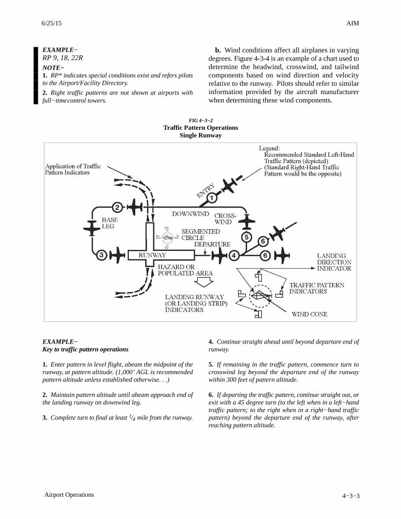
AIM4/3/14
4−3−3Airport Operations
EXAMPLE−RP 9, 18, 22RNOTE−1. RP* indicates special conditions exist and refers pilotsto the Airport/Facility Directory.
2. Right traffic patterns are not shown at airports withfull−time control towers.
b. Wind conditions affect all airplanes in varyingdegrees. Figure 4-3-4 is an example of a chart used todetermine the headwind, crosswind, and tailwindcomponents based on wind direction and velocityrelative to the runway. Pilots should refer to similarinformation provided by the aircraft manufacturerwhen determining these wind components.
FIG 4−3−2
Traffic Pattern OperationsSingle Runway
EXAMPLE−Key to traffic pattern operations
1. Enter pattern in level flight, abeam the midpoint of therunway, at pattern altitude. (1,000’ AGL is recommendedpattern altitude unless established otherwise. . .)
2. Maintain pattern altitude until abeam approach end ofthe landing runway on downwind leg.
3. Complete turn to final at least 1/4 mile from the runway.
4. Continue straight ahead until beyond departure end ofrunway.
5. If remaining in the traffic pattern, commence turn tocrosswind leg beyond the departure end of the runwaywithin 300 feet of pattern altitude.
6. If departing the traffic pattern, continue straight out, orexit with a 45 degree turn (to the left when in a left−handtraffic pattern; to the right when in a right−hand trafficpattern) beyond the departure end of the runway, afterreaching pattern altitude.
6/25/15 AIM
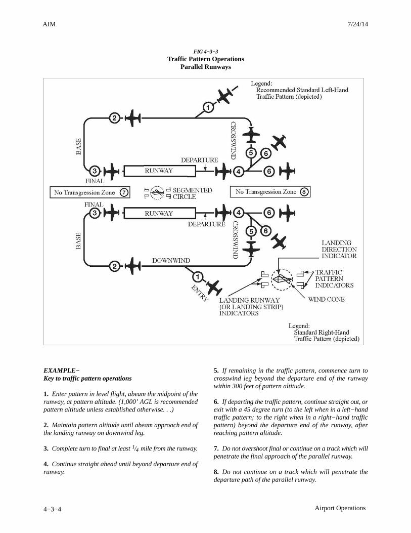
AIM 4/3/14
4−3−4 Airport Operations
FIG 4−3−3
Traffic Pattern OperationsParallel Runways
EXAMPLE−Key to traffic pattern operations
1. Enter pattern in level flight, abeam the midpoint of therunway, at pattern altitude. (1,000’ AGL is recommendedpattern altitude unless established otherwise. . .)
2. Maintain pattern altitude until abeam approach end ofthe landing runway on downwind leg.
3. Complete turn to final at least 1/4 mile from the runway.
4. Continue straight ahead until beyond departure end ofrunway.
5. If remaining in the traffic pattern, commence turn tocrosswind leg beyond the departure end of the runwaywithin 300 feet of pattern altitude.
6. If departing the traffic pattern, continue straight out, orexit with a 45 degree turn (to the left when in a left−handtraffic pattern; to the right when in a right−hand trafficpattern) beyond the departure end of the runway, afterreaching pattern altitude.
7. Do not overshoot final or continue on a track which willpenetrate the final approach of the parallel runway.
8. Do not continue on a track which will penetrate thedeparture path of the parallel runway.
3/15/077110.65R CHG 2AIM 7/24/14

AIM4/3/14
4−3−17Airport Operations
b. Although the traffic signal light offers theadvantage that some control may be exercised overnonradio equipped aircraft, pilots should be cogni-zant of the disadvantages which are:
1. Pilots may not be looking at the control towerat the time a signal is directed toward their aircraft.
2. The directions transmitted by a light signalare very limited since only approval or disapproval ofa pilot’s anticipated actions may be transmitted. Nosupplement or explanatory information may betransmitted except by the use of the “GeneralWarning Signal” which advises the pilot to be on thealert.
c. Between sunset and sunrise, a pilot wishing toattract the attention of the control tower should turnon a landing light and taxi the aircraft into a position,clear of the active runway, so that light is visible to thetower. The landing light should remain on untilappropriate signals are received from the tower.
d. Airport Traffic Control Tower Light GunSignals. (See TBL 4−3−1.)
e. During daylight hours, acknowledge towertransmissions or light signals by moving the aileronsor rudder. At night, acknowledge by blinking thelanding or navigation lights. If radio malfunctionoccurs after departing the parking area, watch thetower for light signals or monitor tower frequency.
TBL 4−3−1
Airport Traffic Control Tower Light Gun Signals
Meaning
Color and Type of SignalMovement of Vehicles,
Equipment and Personnel Aircraft on the Ground Aircraft in Flight
Steady green Cleared to cross, proceed or go Cleared for takeoff Cleared to land
Flashing green Not applicable Cleared for taxi Return for landing (to befollowed by steady green at theproper time)
Steady red STOP STOP Give way to other aircraft andcontinue circling
Flashing red Clear the taxiway/runway Taxi clear of the runway in use Airport unsafe, do not land
Flashing white Return to starting point on airport Return to starting point on airport Not applicable
Alternating red and green Exercise extreme caution Exercise extreme caution Exercise extreme caution
4−3−14. Communications
a. Pilots of departing aircraft should communicatewith the control tower on the appropriate groundcontrol/clearance delivery frequency prior to startingengines to receive engine start time, taxi and/orclearance information. Unless otherwise advised bythe tower, remain on that frequency during taxiingand runup, then change to local control frequencywhen ready to request takeoff clearance.NOTE−Pilots are encouraged to monitor the local tower frequencyas soon as practical consistent with other ATCrequirements.REFERENCE−AIM, Automatic Terminal Information Service (ATIS),Paragraph 4−1−13.
b. The tower controller will consider that pilots ofturbine−powered aircraft are ready for takeoff whenthey reach the runway or warm−up block unlessadvised otherwise.
c. The majority of ground control frequencies arein the 121.6−121.9 MHz bandwidth. Ground controlfrequencies are provided to eliminate frequencycongestion on the tower (local control) frequency andare limited to communications between the tower andaircraft on the ground and between the tower andutility vehicles on the airport, provide a clear VHFchannel for arriving and departing aircraft. They areused for issuance of taxi information, clearances, andother necessary contacts between the tower andaircraft or other vehicles operated on the airport. Apilot who has just landed should not change from thetower frequency to the ground control frequency untildirected to do so by the controller. Normally, only oneground control frequency is assigned at an airport;however, at locations where the amount of traffic sowarrants, a second ground control frequency and/oranother frequency designated as a clearance deliveryfrequency, may be assigned.
6/25/15 AIM
AIM 4/3/14
4−3−18 Airport Operations
d. A controller may omit the ground or localcontrol frequency if the controller believes the pilotknows which frequency is in use. If the groundcontrol frequency is in the 121 MHz bandwidth thecontroller may omit the numbers preceding thedecimal point; e.g., 121.7, “CONTACT GROUNDPOINT SEVEN.” However, if any doubt exists as towhat frequency is in use, the pilot should promptlyrequest the controller to provide that information.
e. Controllers will normally avoid issuing a radiofrequency change to helicopters, known to besingle−piloted, which are hovering, air taxiing, orflying near the ground. At times, it may be necessaryfor pilots to alert ATC regarding single pilotoperations to minimize delay of essential ATCcommunications. Whenever possible, ATC instruc-tions will be relayed through the frequency beingmonitored until a frequency change can beaccomplished. You must promptly advise ATC if youare unable to comply with a frequency change. Also,you should advise ATC if you must land toaccomplish the frequency change unless it is clear thelanding will have no impact on other air traffic;e.g., on a taxiway or in a helicopter operating area.
4−3−15. Gate Holding Due to DepartureDelays
a. Pilots should contact ground control orclearance delivery prior to starting engines as gatehold procedures will be in effect whenever departuredelays exceed or are anticipated to exceed15 minutes. The sequence for departure will bemaintained in accordance with initial call up unlessmodified by flow control restrictions. Pilots shouldmonitor the ground control or clearance deliveryfrequency for engine startup advisories or newproposed start time if the delay changes.
b. The tower controller will consider that pilots ofturbine−powered aircraft are ready for takeoff whenthey reach the runway or warm−up block unlessadvised otherwise.
4−3−16. VFR Flights in Terminal Areas
Use reasonable restraint in exercising the prerogativeof VFR flight, especially in terminal areas. Theweather minimums and distances from clouds areminimums. Giving yourself a greater margin inspecific instances is just good judgment.
a. Approach Area. Conducting a VFR operationin a Class B, Class C, Class D, and Class E surfacearea when the official visibility is 3 or 4 miles is notprohibited, but good judgment would dictate that youkeep out of the approach area.
b. Reduced Visibility. It has always been recog-nized that precipitation reduces forward visibility.Consequently, although again it may be perfectlylegal to cancel your IFR flight plan at any time youcan proceed VFR, it is good practice, whenprecipitation is occurring, to continue IFR operationinto a terminal area until you are reasonably close toyour destination.
c. Simulated Instrument Flights. In conductingsimulated instrument flights, be sure that the weatheris good enough to compensate for the restrictedvisibility of the safety pilot and your greaterconcentration on your flight instruments. Giveyourself a little greater margin when your flight planlies in or near a busy airway or close to an airport.
4−3−17. VFR Helicopter Operations atControlled Airports
a. General.
1. The following ATC procedures and phraseol-ogies recognize the unique capabilities of helicoptersand were developed to improve service to all users.Helicopter design characteristics and user needs oftenrequire operations from movement areas andnonmovement areas within the airport boundary. Inorder for ATC to properly apply these procedures, itis essential that pilots familiarize themselves with thelocal operations and make it known to controllerswhen additional instructions are necessary.
2. Insofar as possible, helicopter operations willbe instructed to avoid the flow of fixed−wing aircraftto minimize overall delays; however, there will bemany situations where faster/larger helicopters maybe integrated with fixed−wing aircraft for the benefitof all concerned. Examples would include IFRflights, avoidance of noise sensitive areas, or use ofrunways/taxiways to minimize the hazardous effectsof rotor downwash in congested areas.
3. Because helicopter pilots are intimatelyfamiliar with the effects of rotor downwash, they arebest qualified to determine if a given operation can beconducted safely. Accordingly, the pilot has the finalauthority with respect to the specific airspeed/altitude
3/15/077110.65R CHG 2AIM 7/24/14
AIM4/3/14
4−7−3Operational Policy/Procedures for the Gulf of Mexico 50 NM Lateral Separation Initiative
Chapter 1. RNP 4 is addressed in Volume II, Part C;Chapter 1.
d. RNP 10 and RNP 4 Job Aids. Operators andauthorities are encouraged to use the RNP 10 or RNP4 Job Aids posted on the FAA Gulf of Mexico 50 NMLateral Separation Initiative Web Page. For U.S.operators, one set of RNP 10 and RNP 4 Job Aidsprovides references to FAA documents. Forinternational operators, a second set of Job Aidsprovide references to the ICAO PBN Manual. TheseJob Aids address the operational and airworthinesselements of aircraft and operator authorization andprovide references to appropriate document para-graphs. The Job Aids provide a method for operatorsto develop and authorities to track the operator/air-craft program elements required for RNP 10 or RNP4 authorization.
e. Qualification of Aircraft Equipped With aSingle Long-Range Navigation System (S-LRNS)For RNP 10 Operations In GoMex CTA’s.
1. Background. S-LRNS operations in the Gulfof Mexico, the Caribbean Sea and the otherdesignated areas have been conducted for at least 25years. Provisions allowing aircraft equipage with aS-LRNS for operations in specified oceanic andoff-shore areas are contained in the followingsections of 14 Code of Federal Regulations (CFR):91.511, 121.351, 125.203 and 135.165.
2. ICAO PBN Manual Reference. In referenceto RNP 10 authorization, the ICAO PBN Manual,Volume II, Part B, Chapter 1, paragraph 1.3.6.2 statesthat: “A State authority may approve the use of asingle LRNS in specific circumstances (e.g., NorthAtlantic MNPS and 14 CFR 121.351 (c) refer). AnRNP 10 approval is still required.”
3. Policy Development. The FAA worked withthe ICAO NACC Office (North American, CentralAmerican and Caribbean), State regulators and ATSproviders in the GoMex and Caribbean areas toimplement a policy for S-LRNS equipped aircraft toqualify for RNP 10 for GoMex operations. AllowingS-LRNS equipped aircraft to qualify for RNP 10enables more operator aircraft to be authorized RNP10, thereby creating a more uniform operatingenvironment for the application of 50 NM lateralseparation. The factors considered were: theshortness of the legs outside the range of ground
navigation aids, the availability of radar and VHFcoverage in a large portion of GoMex airspace and theabsence of events attributed to S-LRNS in GoMexoperations.
4. Document Revision. The following docu-ments were revised or created to enableimplementation of the S-LRNS/RNP 10 qualifica-tion policy:
(a) FAA Order 8400.12
(b) FAA Order 8900.1 (Flight StandardsInformation Management System (FSIMS))
(c) Paragraph B054 of FAA OperationsSpecifications and Management Specifications(Class II Navigation Using Single Long-RangeNavigation System)
(d) LOA B054 (Class II Navigation UsingSingle Long-Range Navigation System (S-LRNS)Equipped Airplane Authorized RNP 10) (LOA’s areapplicable to International General Aviation operat-ors.)
(e) FAA RNP 10 Job Aid with FAA Order8400.12 references
(f) RNP 10 Job Aid with ICAO PBN Manualreferences
5. S-LRNS/RNP 10 Authorization Limited ToGoMex. At this time, S-LRNS qualification for RNP10 only applies to GoMex operations. Any expansionof this provision will require assessment andagreement by the appropriate State authorities.
f. RNP 10 Time Limit for INS or IRU OnlyEquipped Aircraft. Operators should review theirAirplane Flight Manual (AFM), AFM Supplement orother appropriate documents and/or contact theairplane or avionics manufacturer to determine theRNP 10 time limit applicable to their aircraft. Theywill then need to determine its effect, if any, on theiroperation. Unless otherwise approved, the basic RNP10 time limit is 6.2 hours between position updatesfor aircraft on which Inertial Navigation Systems(INS) or Inertial Reference Units (IRU) provide theonly source of long range navigation. Extended RNP10 time limits of 10 hours and greater are alreadyapproved for many IRU systems. FAA Order 8400.12contains provisions for extending RNP 10 timelimits.

AIM 4/3/14
4−7−4 Operational Policy/Procedures for the Gulf of Mexico 50 NM Lateral Separation Initiative
4−7−8. Flight Planning Requirements
Operators must make ICAO flight plan annotationsin accordance with this paragraph and, if applicable,Paragraph 4−7−5, Provisions for Accommodation ofNonRNP10 Aircraft (Aircraft Not Authorized RNP10 or RNP 4).
a. ICAO Flight Plan Requirement. ICAO flightplans must be filed for operation on oceanic routesand areas in the Houston Oceanic CTA/FIR, the Gulfof Mexico portion of the Miami CTA/FIR, theMonterrey CTA and Merida High CTA.
b. To inform ATC that they have obtained RNP 10or RNP 4 authorization and are eligible for 50 NMlateral separation, operators must:
1. Annotate ICAO Flight Plan Item 10(Equipment) with the letter “R” and
2. Annotate Item 18 (Other Information) with,as appropriate, “PBN/A1” (for RNP10) or “PBN/L1”(for RNP4).
NOTE−1. See paragraph 4−7−8e. It provides recommendedfiling practices for domestic U.S. RNAV operations andfiling with EUROCONTROL.
2. On the ICAO Flight Plan, the letter “R” in Item 10indicates that the flight is authorized for PBN operations.Item 18 PBN/ indicates the types of PBN capabilities thatare authorized.
c. 50 NM lateral separation will only be applied tooperators/aircraft that annotate the ICAO flight planin accordance with this policy. (See 4−7−8 b.)
d. Operators that have not obtained RNP 10 orRNP 4 authorization must not annotate ICAO flightplan Item 18 (Other information) with “PBN/A1” or“PBN/L1”, but must follow the practices detailed inparagraph 4−7−5.
e. Recommendation for Filing to Show DomesticU.S. RNAV and Oceanic RNP Capabilities.
1. Explanation. The FAA program that allowsoperators to communicate their domestic U.S. RNAVcapabilities to ATC. It is explained in paragraph5−1−9 b 8 items 18 (c) and 18 (d).
2. Recommendation. It is recommended thatoperators provide their PBN capability for oceanicoperations by filing: “PBN/A1” (for RNP10) or“PBN/L1” (for RNP4). For domestic operations,
operators should indicate their PBN capability perparagraph 5−1−9 b 8 items 18 (c) and 18 (d).
3. Multiple NAV/ Entries. Operators should beaware that if they make multiple “NAV/” entries in aflight plan filed with EUROCONTROL, only the last“NAV/” entry will be forwarded to the next ATCfacility. For example, if “NAV/RNVD1E2A1” and“NAV/RNP10” are entered, only “NAV/RNP10” willbe forwarded. Multiple “NAV/” entries should,therefore, be consolidated following a single “NAV/”indicator.
4. Recommendation. Item 18 entries made inaccordance with paragraph 4-7-8 e 2. above will limitthe number of characters needed to show domesticU.S. RNAV and oceanic RNP capabilities andmitigate the chance that one or the other will not beforwarded for use by FAA domestic and oceanicautomation systems.
f. Implementation of ICAO Doc 4444, RevisedAppendix 2 (Flight Plan). ICAO Doc 4444,Amendment 1 revises Appendix 2 (Flight Plan).Specifically, Amendment 1 revises the flight planannotations in Item 10 (Equipment) and Item 18(Other Information) that show aircraft communica-tions, navigation and surveillance capabilities. Thenew Appendix 2 flight plan annotations will berequired on 15 November 2012. The followingWebsites provide information on implementationplanning:
1. FAA Website: http://www.faa.gov/go/fpl2012.
2. ICAO Flight Plan Implementation TrackingSystem (FITS): http://www2.icao.int/en/FITS/Pages/home.aspx.
4−7−9. Pilot and Dispatcher Procedures:Basic and In-flight ContingencyProcedures
a. Basic Pilot Procedures. The RNP 10 and RNP4 Job Aids contain references to pilot and, ifapplicable, dispatcher procedures contained in:
1. FAA Order 8400.12C (RNP 10), Appendix D(Training Programs and Operating Practices andProcedures)
2. FAA Order 8400.33 (RNP 4): Paragraph 9(Operational Requirements) and Paragraph 10(Training Programs, Operating Practices and Proced-ures)
3/15/077110.65R CHG 2AIM 6/25/15
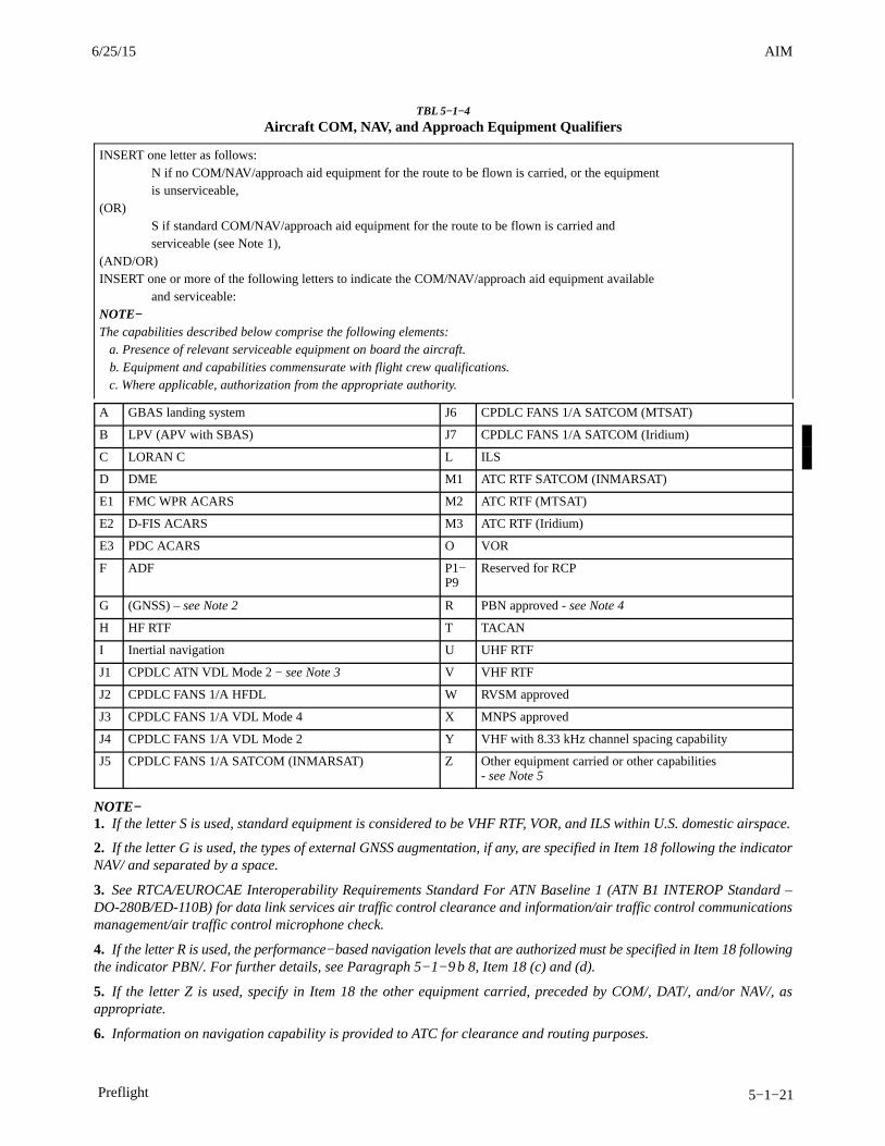
AIM4/3/14
5−1−21Preflight
TBL 5−1−4
Aircraft COM, NAV, and Approach Equipment Qualifiers
INSERT one letter as follows:N if no COM/NAV/approach aid equipment for the route to be flown is carried, or the equipment is unserviceable,
(OR) S if standard COM/NAV/approach aid equipment for the route to be flown is carried and serviceable (see Note 1),
(AND/OR)INSERT one or more of the following letters to indicate the COM/NAV/approach aid equipment available
and serviceable:NOTE−The capabilities described below comprise the following elements: a. Presence of relevant serviceable equipment on board the aircraft. b. Equipment and capabilities commensurate with flight crew qualifications. c. Where applicable, authorization from the appropriate authority.
A GBAS landing system J6 CPDLC FANS 1/A SATCOM (MTSAT)
B LPV (APV with SBAS) J7 CPDLC FANS 1/A SATCOM (Iridium)
C LORAN C L ILS
D DME M1 ATC RTF SATCOM (INMARSAT)
E1 FMC WPR ACARS M2 ATC RTF (MTSAT)
E2 D-FIS ACARS M3 ATC RTF (Iridium)
E3 PDC ACARS O VOR
F ADF P1−P9
Reserved for RCP
G (GNSS) – see Note 2 R PBN approved - see Note 4
H HF RTF T TACAN
I Inertial navigation U UHF RTF
J1 CPDLC ATN VDL Mode 2 − see Note 3 V VHF RTF
J2 CPDLC FANS 1/A HFDL W RVSM approved
J3 CPDLC FANS 1/A VDL Mode 4 X MNPS approved
J4 CPDLC FANS 1/A VDL Mode 2 Y VHF with 8.33 kHz channel spacing capability
J5 CPDLC FANS 1/A SATCOM (INMARSAT) Z Other equipment carried or other capabilities - see Note 5
NOTE−1. If the letter S is used, standard equipment is considered to be VHF RTF, VOR, and ILS within U.S. domestic airspace.
2. If the letter G is used, the types of external GNSS augmentation, if any, are specified in Item 18 following the indicatorNAV/ and separated by a space.
3. See RTCA/EUROCAE Interoperability Requirements Standard For ATN Baseline 1 (ATN B1 INTEROP Standard –DO-280B/ED-110B) for data link services air traffic control clearance and information/air traffic control communicationsmanagement/air traffic control microphone check.
4. If the letter R is used, the performance−based navigation levels that are authorized must be specified in Item 18 followingthe indicator PBN/. For further details, see Paragraph 5−1−9 b 8, Item 18 (c) and (d).
5. If the letter Z is used, specify in Item 18 the other equipment carried, preceded by COM/, DAT/, and/or NAV/, asappropriate.
6. Information on navigation capability is provided to ATC for clearance and routing purposes.
6/25/15 AIM
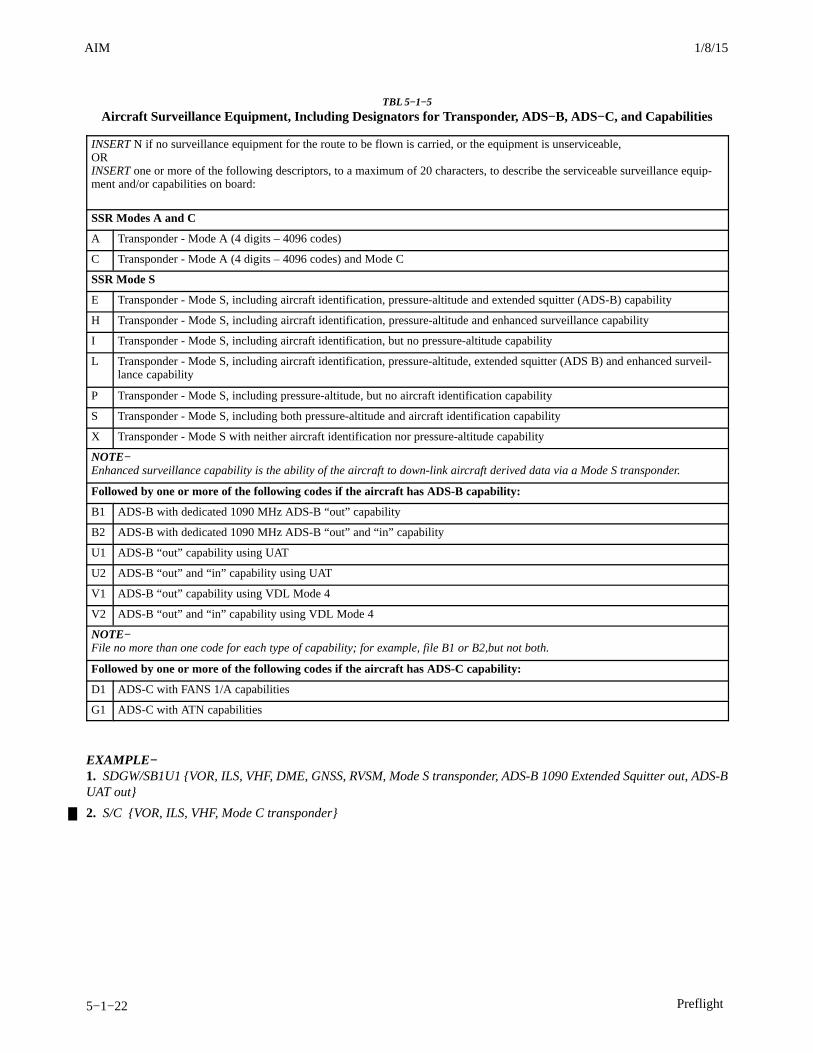
AIM 4/3/14
5−1−22 Preflight
TBL 5−1−5
Aircraft Surveillance Equipment, Including Designators for Transponder, ADS−B, ADS−C, and Capabilities
INSERT N if no surveillance equipment for the route to be flown is carried, or the equipment is unserviceable,ORINSERT one or more of the following descriptors, to a maximum of 20 characters, to describe the serviceable surveillance equip-ment and/or capabilities on board:
SSR Modes A and C
A Transponder - Mode A (4 digits – 4096 codes)
C Transponder - Mode A (4 digits – 4096 codes) and Mode C
SSR Mode S
E Transponder - Mode S, including aircraft identification, pressure-altitude and extended squitter (ADS-B) capability
H Transponder - Mode S, including aircraft identification, pressure-altitude and enhanced surveillance capability
I Transponder - Mode S, including aircraft identification, but no pressure-altitude capability
L Transponder - Mode S, including aircraft identification, pressure-altitude, extended squitter (ADS B) and enhanced surveil-lance capability
P Transponder - Mode S, including pressure-altitude, but no aircraft identification capability
S Transponder - Mode S, including both pressure-altitude and aircraft identification capability
X Transponder - Mode S with neither aircraft identification nor pressure-altitude capability
NOTE−Enhanced surveillance capability is the ability of the aircraft to down-link aircraft derived data via a Mode S transponder.
Followed by one or more of the following codes if the aircraft has ADS-B capability:
B1 ADS-B with dedicated 1090 MHz ADS-B “out” capability
B2 ADS-B with dedicated 1090 MHz ADS-B “out” and “in” capability
U1 ADS-B “out” capability using UAT
U2 ADS-B “out” and “in” capability using UAT
V1 ADS-B “out” capability using VDL Mode 4
V2 ADS-B “out” and “in” capability using VDL Mode 4
NOTE−File no more than one code for each type of capability; for example, file B1 or B2,but not both.
Followed by one or more of the following codes if the aircraft has ADS-C capability:
D1 ADS-C with FANS 1/A capabilities
G1 ADS-C with ATN capabilities
EXAMPLE−1. SDGW/SB1U1 {VOR, ILS, VHF, DME, GNSS, RVSM, Mode S transponder, ADS-B 1090 Extended Squitter out, ADS-BUAT out}
2. S/C {VOR, ILS, VHF, Mode C transponder}
3/15/077110.65R CHG 2AIM 1/8/15

AIM4/3/14
5−2−7Departure Procedures
ture. This assessment area is limited to 25 NM fromthe airport in nonmountainous areas and 46 NM indesignated mountainous areas. Beyond this distance,the pilot is responsible for obstacle clearance if notoperating on a published route, if below (having notreached) the MEA or MOCA of a published route, oran ATC assigned altitude. See FIG 5−2−1. (Ref 14
CFR 91.177 for further information on en route alti-tudes.)
NOTE−ODPs are normally designed to terminate within these dis-tance limitations, however, some ODPs will contain routesthat may exceed 25/46 NM; these routes will ensureobstacle protection until reaching the end of the ODP.
FIG 5−2−1
Diverse Departure Obstacle Assessment to 25/46 NM
4. Obstacles that are located within 1 NM of theDER and penetrate the 40:1 OCS are referred to as“low, close−in obstacles.” The standard requiredobstacle clearance (ROC) of 48 feet per NM to clearthese obstacles would require a climb gradient greaterthan 200 feet per NM for a very short distance, onlyuntil the aircraft was 200 feet above the DER. Toeliminate publishing an excessive climb gradient, theobstacle AGL/MSL height and location relative to theDER is noted in the “Take−off Minimums and(OBSTACLE) Departure Procedures” section of agiven Terminal Procedures Publication (TPP) book-let. The purpose of this note is to identify theobstacle(s) and alert the pilot to the height and loca-tion of the obstacle(s) so they can be avoided. Thiscan be accomplished in a variety of ways, e.g., thepilot may be able to see the obstruction and maneuveraround the obstacle(s) if necessary; early liftoff/climbperformance may allow the aircraft to cross wellabove the obstacle(s); or if the obstacle(s) cannot bevisually acquired during departure, preflight plan-ning should take into account what turns or othermaneuver may be necessary immediately aftertakeoff to avoid the obstruction(s).
5. Climb gradients greater than 200 FPNM arespecified when required to support procedure designconstraints, obstacle clearance, and/or airspace re-strictions. Compliance with a climb gradient for thesepurposes is mandatory when the procedure is part ofthe ATC clearance, unless increased takeoff minim-ums are provided and weather conditions allowcompliance with these minimums. Additionally, ATCrequired crossing restrictions may also require climbgradients greater than 200 FPNM. These climb gradi-ents may be amended or canceled at ATC’s discretion.Multiple ATC climb gradients are permitted. An ATCclimb gradient will not be used on an ODP.
EXAMPLE−“Cross ALPHA intersection at or below 4000; maintain6000.” The pilot climbs at least 200 FPNM to 6000. If 4000is reached before ALPHA, the pilot levels off at 4000 untilpassing ALPHA; then immediately resumes at least 200FPNM climb.
EXAMPLE−“TAKEOFF MINIMUMS: RWY 27, Standard with a min-imum climb of 280’ per NM to 2500, ATC climb of 310’ perNM to 4000 ft.” A climb of at least 280 FPNM is requiredto 2500 and is mandatory when the departure procedure is

AIM 4/3/14
5−2−8 Departure Procedures
included in the ATC clearance. ATC requires a climb gradi-ent of 310 FPNM to 4000, however, this ATC climbgradient may be amended or canceled.
6. Climb gradients may be specified only to analtitude/fix, above which the normal gradient applies.
EXAMPLE−“Minimum climb 340 FPNM to ALPHA.” The pilot climbsat least 340 FPNM to ALPHA, then at least 200 FPNM toMIA.
7. Some DPs established solely for obstacleavoidance require a climb in visual conditions tocross the airport or an on−airport NAVAID in a speci-fied direction, at or above a specified altitude. Theseprocedures are called Visual Climb Over the Airport(VCOA).
EXAMPLE−“Climb in visual conditions so as to cross the McElory Air-port southbound, at or above 6000, then climb viaKeemmling radial zero three three to Keemmling VOR-TAC.”
c. Who is responsible for obstacle clearance? DPsare designed so that adherence to the procedure by thepilot will ensure obstacle protection. Additionally:
1. Obstacle clearance responsibility also restswith the pilot when he/she chooses to climb in visualconditions in lieu of flying a DP and/or depart underincreased takeoff minima rather than fly the climbgradient. Standard takeoff minima are one statutemile for aircraft having two engines or less and one−half statute mile for aircraft having more than twoengines. Specified ceiling and visibility minima(VCOA or increased takeoff minima) will allow visu-al avoidance of obstacles until the pilot enters thestandard obstacle protection area. Obstacle avoid-ance is not guaranteed if the pilot maneuvers fartherfrom the airport than the specified visibility minimumprior to reaching the specified altitude. DPs may alsocontain what are called Low Close in Obstacles.These obstacles are less than 200 feet above the de-parture end of runway elevation and within one NMof the runway end, and do not require increased take-off minimums. These obstacles are identified on theSID chart or in the Take−off Minimums and (Ob-stacle) Departure Procedures section of the U. S.Terminal Procedure booklet. These obstacles are es-pecially critical to aircraft that do not lift off untilclose to the departure end of the runway or whichclimb at the minimum rate. Pilots should also consid-er drift following lift−off to ensure sufficient
clearance from these obstacles. That segment of theprocedure that requires the pilot to see and avoid ob-stacles ends when the aircraft crosses the specifiedpoint at the required altitude. In all cases continuedobstacle clearance is based on having climbed a mini-mum of 200 feet per nautical mile to the specifiedpoint and then continuing to climb at least 200 footper nautical mile during the departure until reachingthe minimum enroute altitude, unless specified other-wise.
2. ATC may assume responsibility for obstacleclearance by vectoring the aircraft prior to reachingthe minimum vectoring altitude by using a DiverseVector Area (DVA). The DVA may be established be-low the Minimum Vectoring Altitude (MVA) orMinimum IFR Altitude (MIA) in a radar environmentat the request of Air Traffic. This type of DP meets theTERPS criteria for diverse departures, obstacles, andterrain avoidance in which random radar vectors be-low the MVA/MIA may be issued to departingaircraft. The DVA has been assessed for departureswhich do not follow a specific ground track, but willremain within the specified area.
(a) The existence of a DVA will be noted inthe Takeoff Minimums and Obstacle Departure Pro-cedure section of the U.S. Terminal ProceduresPublication (TPP). The Takeoff Departure procedurewill be listed first, followed by any applicable DVA.
EXAMPLE−DIVERSE VECTOR AREA (RADAR VECTORS)AMDT 1 14289 (FAA)
Rwy 6R, headings as assigned by ATC; requiresminimum climb of 290’ per NM to 400. Rwys 6L, 7L, 7R, 24R, 25R, headings as assigned by ATC.
(b) Pilots should be aware that Air Traffic fa-cilities may utilize a climb gradient greater than thestandard 200 FPNM in a DVA. This information willbe identified in the DVA text for pilot evaluationagainst the aircraft’s available climb performance. Pi-lots should note that the DVA has been assessed fordepartures which do not follow a specific groundtrack. ATC may also vector an aircraft off a previ-ously assigned DP. In all cases, the minimum 200FPNM climb gradient is assumed unless a higherclimb gradient is specified on the departure, andobstacle clearance is not provided by ATC until thecontroller begins to provide navigational guidance inthe form of radar vectors.
3/15/077110.65R CHG 2AIM 6/25/15
AIM4/3/14
5−2−9Departure Procedures
NOTE−As is always the case, when used by the controller duringdeparture, the term “radar contact” should not be inter-preted as relieving pilots of their responsibility to maintainappropriate terrain and obstruction clearance which mayinclude flying the obstacle DP.
3. Pilots must preplan to determine if the aircraftcan meet the climb gradient (expressed in feet pernautical mile) required by the departure procedure,and be aware that flying at a higher than anticipatedground speed increases the climb rate requirement infeet per minute. Higher than standard climb gradientsare specified by a note on the departure procedurechart for graphic DPs, or in the Take−Off Minimumsand (Obstacle) Departure Procedures section of theU.S. Terminal Procedures booklet for textual ODPs.The required climb gradient, or higher, must be main-tained to the specified altitude or fix, then thestandard climb gradient of 200 ft/NM can be re-sumed. A table for the conversion of climb gradient(feet per nautical mile) to climb rate (feet per minute),at a given ground speed, is included on the inside ofthe back cover of the U.S. Terminal Procedures book-lets.
d. Where are DPs located? DPs will be listed byairport in the IFR Takeoff Minimums and (Obstacle)Departure Procedures Section, Section L, of the Ter-minal Procedures Publications (TPPs). If the DP istextual, it will be described in TPP Section L. SIDsand complex ODPs will be published graphically andnamed. The name will be listed by airport name andrunway in Section L. Graphic ODPs will also have theterm “(OBSTACLE)” printed in the charted proce-dure title, differentiating them from SIDs.
1. An ODP that has been developed solely forobstacle avoidance will be indicated with the symbol“T” on appropriate Instrument Approach Procedure(IAP) charts and DP charts for that airport. The “T”symbol will continue to refer users to TPP Section C.In the case of a graphic ODP, the TPP Section C willonly contain the name of the ODP. Since there may beboth a textual and a graphic DP, Section C should stillbe checked for additional information. The nonstan-dard takeoff minimums and minimum climbgradients found in TPP Section C also apply tocharted DPs and radar vector departures unless differ-ent minimums are specified on the charted DP.Takeoff minimums and departure procedures apply toall runways unless otherwise specified. New graphic
DPs will have all the information printed on thegraphic depiction. As a general rule, ATC will onlyassign an ODP from a nontowered airport when com-pliance with the ODP is necessary for aircraft toaircraft separation. Pilots may use the ODP to helpensure separation from terrain and obstacles.
e. Responsibilities
1. Each pilot, prior to departing an airport on anIFR flight should:
(a) Consider the type of terrain and other ob-stacles on or in the vicinity of the departure airport;
(b) Determine whether an ODP is available;
(c) Determine if obstacle avoidance can bemaintained visually or if the ODP should be flown;and
(d) Consider the effect of degraded climb per-formance and the actions to take in the event of anengine loss during the departure. Pilots should notifyATC as soon as possible of reduced climb capabilityin that circumstance.
NOTE−Guidance concerning contingency procedures thataddress an engine failure on takeoff after V1 speed on alarge or turbine−powered transport category airplanemay be found in AC 120−91, Airport Obstacle Analysis.
2. Pilots should not exceed a published speed re-striction associated with a SID waypoint until passingthat waypoint.
3. After an aircraft is established on an SID andsubsequently vectored or cleared off of the SID orSID transition, pilots must consider the SID canceled,unless the controller adds “expect to resume SID;” pi-lots should then be prepared to rejoin the SID at asubsequent fix or procedure leg. ATC may also inter-rupt the vertical navigation of a SID and providealternate altitude instructions while the aircraft re-mains established on the published lateral path.Aircraft may not be vectored off of an ODP or issuedan altitude lower than a published altitude on an ODPuntil at or above the MVA/MIA, at which time theODP is canceled.
4. Aircraft instructed to resume a proceduresuch as a DP or SID which contains speed and/or alti-tude restrictions, must be:
(a) Issued/reissued all applicable restrictions,or
6/25/15 AIM

AIM 4/3/14
5−2−10 Departure Procedures
(b) Advised to comply with restrictions or re-sume published speed.
EXAMPLE−“Resume the Solar One departure, comply with restric-tions.”“Proceed direct CIROS, resume the Solar One departure,comply with restrictions.”
5. A clearance for a SID which contains pub-lished altitude restrictions may be issued using thephraseology “climb via.” Climb via is an abbreviatedclearance that requires compliance with the proced-ure lateral path, associated speed and altituderestrictions along the cleared route or procedure.Clearance to “climb via” authorizes the pilot to:
(a) When used in the IFR departure clearance,in a PDC, DCL or when cleared to a waypoint depic-ted on a SID, to join the procedure after departure orto resume the procedure.
(b) When vertical navigation is interruptedand an altitude is assigned to maintain which is notcontained on the published procedure, to climb fromthat previously-assigned altitude at pilot’s discretionto the altitude depicted for the next waypoint.
(c) Once established on the depicted depar-ture, to navigate laterally and climb to meet allpublished or assigned altitude and speed restrictions.
NOTE−1. When otherwise cleared along a route or procedure thatcontains published speed restrictions, the pilot must com-ply with those speed restrictions independent of a climb viaclearance.
2. ATC anticipates pilots will begin adjusting speed theminimum distance necessary prior to a published speed re-striction so as to cross the waypoint/fix at the publishedspeed. Once at the published speed ATC expects pilots willmaintain the published speed until additional adjustmentis required to comply with further published or ATC as-signed speed restrictions or as required to ensurecompliance with 14 CFR Section 91.117.
3. If ATC interrupts lateral/vertical navigation while anaircraft is flying a SID, ATC must ensure obstacle clear-ance. When issuing a “climb via” clearance to join orresume a procedure ATC must ensure obstacle clearanceuntil the aircraft is established on the lateral and verticalpath of the SID.
4. ATC will assign an altitude to cross if no altitude is de-picted at a waypoint/fix or when otherwise necessary/required, for an aircraft on a direct route to a waypoint/fixwhere the SID will be joined or resumed.
5. SIDs will have a “top altitude;” the “top altitude” is thecharted “maintain” altitude contained in the proceduredescription or assigned by ATC.
REFERENCE−FAAJO 7110.65, Para 5-6-2, MethodsPCG, Climb Via, Top Altitude
EXAMPLE−1. Lateral route clearance:
“Cleared Loop Six departure.”
NOTE−The aircraft must comply with the SID lateral path, and anypublished speed restrictions.
2. Routing with assigned altitude:“Cleared Loop Six departure, climb and maintain
four thousand.”
NOTE−The aircraft must comply with the SID lateral path, and anypublished speed restriction while climbing unrestricted tofour thousand.
3. (A pilot filed a flight plan to the Johnston Airport usingthe Scott One departure, Jonez transition, then Q-145. Thepilot filed for FL350. The Scott One includes altituderestrictions, a top altitude and instructions to expect thefiled altitude ten minutes after departure). Beforedeparture ATC uses PDC, DCL or clearance delivery toissue the clearance:
“Cleared to Johnston Airport, Scott One departure,Jonez transition, Q-OneForty-five. Climb via SID.”
NOTE−In Example 3, the aircraft must comply with the Scott Onedeparture lateral path and any published speed and alti-tude restrictions while climbing to the SID top altitude.
4. (Using the Example 3 flight plan, ATC determines thetop altitude must be changed to FL180). The clearance willread:
“Cleared to Johnston Airport, Scott One departure,Jonez transition, Q-One Forty-five, Climb via SID exceptmaintain flight level one eight zero.”
NOTE−In Example 4, the aircraft must comply with the Scott Onedeparture lateral path and any published speed and alti-tude restrictions while climbing to FL180. The aircraftmust stop climb at FL180 until issued further clearance byATC.
5. (An aircraft was issued the Suzan Two departure,“climb via SID” in the IFR departure clearance. Afterdeparture ATC must change a waypoint crossingrestriction). The clearance will be:
“Climb via SID except cross Mkala at or above seventhousand.”
NOTE−In Example 5, the aircraft will comply with the Suzan Two
3/15/077110.65R CHG 2AIM 6/25/15
AIM4/3/14
5−2−11Departure Procedures
departure lateral path and any published speed and alti-tude restrictions and climb so as to cross Mkala at or above7,000; remainder of the departure must be flown as pub-lished.
6. (An aircraft was issued the Teddd One departure,“climb via SID” in the IFR departure clearance. Aninterim altitude of 10,000 was issued instead of thepublished top altitude of FL 230). After departure ATC isable to issue the published top altitude. The clearance willbe:
“Climb via SID.”
NOTE−In Example 6, the aircraft will track laterally and verticallyon the Teddd One departure and initially climb to 10,000;Once re-issued the “climb via” clearance the interim alti-tude is canceled aircraft will continue climb to FL230while complying with published restrictions.
7. (An aircraft was issued the Bbear Two departure,“climb via SID” in the IFR departure clearance. Aninterim altitude of 16,000 was issued instead of thepublished top altitude of FL 190). After departure, ATC isable to issue a top altitude of FL300 and still requirescompliance with the published SID restrictions. Theclearance will be:
“Climb via SID except maintain flight level three zerozero.”
NOTE−In Example 7, the aircraft will track laterally and verticallyon the Bbear Two departure and initially climb to 16,000;Once re-issued the “climb via” clearance the interim alti-tude is canceled and the aircraft will continue climb toFL300 while complying with published restrictions.
8. (An aircraft was issued the Bizee Two departure, “climbvia SID.” After departure, ATC vectors the aircraft off ofthe SID, and then issues a direct routing to rejoin the SIDat Rockr waypoint which does not have a published altituderestriction. ATC wants the aircraft to cross at or above10,000). The clearance will read:
“Proceed direct Rockr, cross Rockr at or aboveone-zero thousand, climb via the Bizee Two departure.”
NOTE−In Example 8, the aircraft will join the Bizee Two SID atRockr at or above 10,000 and then comply with the pub-lished lateral path and any published speed or altituderestrictions while climbing to the SID top altitude.
9. (An aircraft was issued the Suzan Two departure,“climb via SID” in the IFR departure clearance. Afterdeparture ATC vectors the aircraft off of the SID, and thenclears the aircraft to rejoin the SID at Dvine waypoint,which has a published crossing restriction). The clearancewill read:
“Proceed direct Dvine, Climb via the Suzan Twodeparture.”
NOTE−In Example 9, the aircraft will join the Suzan Two departureat Dvine, at the published altitude, and then comply withthe published lateral path and any published speed or alti-tude restrictions.
6. Pilots cleared for vertical navigation using thephraseology “climb via” must inform ATC, upon ini-tial contact, of the altitude leaving and any assignedrestrictions not published on the procedure.
EXAMPLE−1. (Cactus 711 is cleared to climb via the Laura Twodeparture. The Laura Two has a top altitude of FL190): “Cactus Seven Eleven leaving two thousand, climbing viathe Laura Two departure.”
2. (Cactus 711 is cleared to climb via the Laura Twodeparture, but ATC changed the top altitude to16,000): “Cactus Seven Eleven leaving two thousand for one-sixthousand, climbing via the Laura Two departure.”
7. If prior to or after takeoff an altitude restric-tion is issued by ATC, all previously issued “ATC”altitude restrictions are canceled including those pub-lished on a SID. Pilots must still comply with allspeed restrictions and lateral path requirements pub-lished on the SID unless canceled by ATC.
EXAMPLE−Prior to takeoff or after departure ATC issues an altitudechange clearance to an aircraft cleared to climb via a SIDbut ATC no longer requires compliance with published alti-tude restrictions:
“Climb and maintain flight level two four zero.”
NOTE−The published SID altitude restrictions are canceled; Theaircraft should comply with the SID lateral path and beginan unrestricted climb to FL240. Compliance with pub-lished speed restrictions is still required unless specificallydeleted by ATC.
8. Altitude restrictions published on an ODP arenecessary for obstacle clearance and/or design con-straints. Compliance with these restrictions ismandatory and CANNOT be lowered or cancelled byATC.
f. RNAV Departure Procedures
All public RNAV SIDs and graphic ODPs areRNAV 1. These procedures generally start with aninitial RNAV or heading leg near the departure end ofrunway (DER). In addition, these procedures requiresystem performance currently met by GPS or DME/DME/IRU RNAV systems that satisfy the criteria
6/25/15 AIM

AIM 4/3/14
5−2−12 Departure Procedures
discussed in AC 90−100A, U.S. Terminal and EnRoute Area Navigation (RNAV) Operations.RNAV 1 procedures must maintain a total system er-ror of not more than 1 NM for 95% of the total flighttime.
REFERENCE−AIM, Global Positioning System (GPS)Paragraph 1−1−18l, Impact of magnetic Variation on RNAV Systems
3/15/077110.65R CHG 2AIM 6/25/15
AIM4/3/14
5−4−27Arrival Procedures
segment of that IAP until the aircraft reaches theinitial fix or navigation facility upon which theprocedure turn is predicated.
EXAMPLE−Cross Redding VOR at or above five thousand, clearedVOR runway three four approach. orFive miles from outer marker, turn right heading three threezero, maintain two thousand until established on thelocalizer, cleared ILS runway three six approach.
NOTE−The altitude assigned will assure IFR obstructionclearance from the point at which the approach clearanceis issued until established on a segment of a published routeor IAP. If uncertain of the meaning of the clearance,immediately request clarification from ATC.
c. Several IAPs, using various navigation andapproach aids may be authorized for an airport. ATCmay advise that a particular approach procedure isbeing used, primarily to expedite traffic. If issued aclearance that specifies a particular approachprocedure, notify ATC immediately if a different oneis desired. In this event it may be necessary for ATCto withhold clearance for the different approach untilsuch time as traffic conditions permit. However, apilot involved in an emergency situation will be givenpriority. If the pilot is not familiar with the specificapproach procedure, ATC should be advised and theywill provide detailed information on the execution ofthe procedure.
REFERENCE−AIM, Advance Information on Instrument Approach, Paragraph 5−4−4.
d. The name of an instrument approach, aspublished, is used to identify the approach, eventhough a component of the approach aid, such as theglideslope on an Instrument Landing System, isinoperative or unreliable. The controller will use thename of the approach as published, but must advisethe aircraft at the time an approach clearance is issuedthat the inoperative or unreliable approach aidcomponent is unusable, except when the title of thepublished approach procedures otherwise allows, forexample, ILS or LOC.
e. Except when being radar vectored to the finalapproach course, when cleared for a specificallyprescribed IAP; i.e., “cleared ILS runway one ninerapproach” or when “cleared approach” i.e., executionof any procedure prescribed for the airport, pilotsmust execute the entire procedure commencing at anIAF or an associated feeder route as described on the
IAP chart unless an appropriate new or revised ATCclearance is received, or the IFR flight plan iscanceled.
f. Pilots planning flights to locations which areprivate airfields or which have instrument approachprocedures based on private navigation aids shouldobtain approval from the owner. In addition, the pilotmust be authorized by the FAA to fly specialinstrument approach procedures associated withprivate navigation aids (see paragraph 5−4−8).Owners of navigation aids that are not for public usemay elect to turn off the signal for whatever reasonthey may have; e.g., maintenance, energyconservation, etc. Air traffic controllers are notrequired to question pilots to determine if they havepermission to land at a private airfield or to useprocedures based on privately owned navigation aids,and they may not know the status of the navigationaid. Controllers presume a pilot has obtainedapproval from the owner and the FAA for use ofspecial instrument approach procedures and is awareof any details of the procedure if an IFR flight planwas filed to that airport.
g. Pilots should not rely on radar to identify a fixunless the fix is indicated as “RADAR” on the IAP.Pilots may request radar identification of an OM, butthe controller may not be able to provide the servicedue either to workload or not having the fix on thevideo map.
h. If a missed approach is required, advise ATCand include the reason (unless initiated by ATC).Comply with the missed approach instructions for theinstrument approach procedure being executed,unless otherwise directed by ATC.REFERENCE−AIM, Missed Approach, Paragraph 5−4−21.AIM, Missed Approach, Paragraph 5−5−5.
5−4−8. Special Instrument ApproachProcedures
Instrument Approach Procedure (IAP) charts reflectthe criteria associated with the U.S. Standard forTerminal Instrument [Approach] Procedures(TERPs), which prescribes standardized methods foruse in developing IAPs. Standard IAPs are publishedin the Federal Register (FR) in accordance withTitle 14 of the Code of Federal Regulations, Part 97,and are available for use by appropriately qualifiedpilots operating properly equipped and airworthyaircraft in accordance with operating rules and
7/24/14 AIM
AIM 4/3/14
5−4−28 Arrival Procedures
procedures acceptable to the FAA. Special IAPs arealso developed using TERPS but are not given publicnotice in the FR. The FAA authorizes only certainindividual pilots and/or pilots in individualorganizations to use special IAPs, and may requireadditional crew training and/or aircraft equipment orperformance, and may also require the use of landingaids, communications, or weather services notavailable for public use. Additionally, IAPs thatservice private use airports or heliports are generallyspecial IAPs. FDC NOTAMs for Specials, FDCT-NOTAMs, may also be used to promulgatesafety-of-flight information relating to Specialsprovided the location has a valid landing areaidentifier and is serviced by the United StatesNOTAM system. Pilots may access NOTAMs onlineor through an FAA Flight Service Station (FSS). FSSspecialists will not automatically provide NOTAMinformation to pilots for special IAPs duringtelephone pre−flight briefings. Pilots who areauthorized by the FAA to use special IAPs mustspecifically request FDC NOTAM information forthe particular special IAP they plan to use.
5−4−9. Procedure Turn and Hold−in−lieu ofProcedure Turn
a. A procedure turn is the maneuver prescribedwhen it is necessary to reverse direction to establishthe aircraft inbound on an intermediate or finalapproach course. The procedure turn orhold−in−lieu−of−PT is a required maneuver when itis depicted on the approach chart, unless cleared byATC for a straight−in approach. Additionally, theprocedure turn or hold−in−lieu−of−PT is notpermitted when the symbol “No PT” is depicted onthe initial segment being used, when a RADARVECTOR to the final approach course is provided,or when conducting a timed approach from a holdingfix. The altitude prescribed for the procedure turn isa minimum altitude until the aircraft is established onthe inbound course. The maneuver must becompleted within the distance specified in theprofile view. For a hold−in−lieu−of−PT, the holdingpattern direction must be flown as depicted and thespecified leg length/timing must not be exceeded.
NOTE−The pilot may elect to use the procedure turn orhold−in−lieu−of−PT when it is not required by theprocedure, but must first receive an amended clearancefrom ATC. If the pilot is uncertain whether the ATCclearance intends for a procedure turn to be conducted orto allow for a straight−in approach, the pilot mustimmediately request clarification from ATC (14 CFRSection 91.123).
1. On U.S. Government charts, a barbed arrowindicates the maneuvering side of the outboundcourse on which the procedure turn is made.Headings are provided for course reversal using the45 degree type procedure turn. However, the point atwhich the turn may be commenced and the type andrate of turn is left to the discretion of the pilot (limitedby the charted remain within xx NM distance). Someof the options are the 45 degree procedure turn, theracetrack pattern, the teardrop procedure turn, or the80 degree � 260 degree course reversal. Racetrackentries should be conducted on the maneuvering sidewhere the majority of protected airspace resides. If anentry places the pilot on the non−maneuvering side ofthe PT, correction to intercept the outbound courseensures remaining within protected airspace. Someprocedure turns are specified by procedural track.These turns must be flown exactly as depicted.
2. Descent to the procedure turn (PT)completion altitude from the PT fix altitude (whenone has been published or assigned by ATC) must notbegin until crossing over the PT fix or abeam andproceeding outbound. Some procedures contain anote in the chart profile view that says “Maintain(altitude) or above until established outbound forprocedure turn” (See FIG 5−4−14). Newerprocedures will simply depict an “at or above”altitude at the PT fix without a chart note (SeeFIG 5−4−15). Both are there to ensure requiredobstacle clearance is provided in the procedure turnentry zone (See FIG 5−4−16). Absence of a chart noteor specified minimum altitude adjacent to the PT fixis an indication that descent to the procedure turnaltitude can commence immediately upon crossingover the PT fix, regardless of the direction of flight.This is because the minimum altitudes in the PT entryzone and the PT maneuvering zone are the same.
3/15/077110.65R CHG 2AIM 6/25/15
AIM4/3/14
5−4−35Arrival Procedures
airport or heliport in sight or, for a helicopterpoint−in−space approach, the prescribed visualreference with the surface is established. Also, if, atany time during the approach the controller considersthat safe guidance for the remainder of the approachcannot be provided, the controller will terminateguidance and instruct the pilot to execute a missedapproach. Similarly, guidance termination andmissed approach will be effected upon pilot requestand, for civil aircraft only, controllers may terminateguidance when the pilot reports the runway,airport/heliport or visual surface route(point−in−space approach) in sight or otherwiseindicates that continued guidance is not required.Radar service is automatically terminated at thecompletion of a radar approach.
NOTE−1. The published MDA for straight−in approaches will beissued to the pilot before beginning descent. When asurveillance approach will terminate in a circle−to−landmaneuver, the pilot must furnish the aircraft approachcategory to the controller. The controller will then providethe pilot with the appropriate MDA.
2. ASR APPROACHES ARE NOT AVAILABLE WHENAN ATC FACILITY IS USING CENRAP.
3. A NO−GYRO APPROACH is available toa pilot under radar control who experiencescircumstances wherein the directional gyro or otherstabilized compass is inoperative or inaccurate.When this occurs, the pilot should so advise ATC andrequest a No−Gyro vector or approach. Pilots ofaircraft not equipped with a directional gyro or otherstabilized compass who desire radar handling mayalso request a No−Gyro vector or approach. The pilotshould make all turns at standard rate and shouldexecute the turn immediately upon receipt ofinstructions. For example, “TURN RIGHT,” “STOPTURN.” When a surveillance or precision approachis made, the pilot will be advised after the aircraft hasbeen turned onto final approach to make turns at halfstandard rate.
5−4−12. Radar Monitoring of InstrumentApproaches
a. PAR facilities operated by the FAA and themilitary services at some joint−use (civil andmilitary) and military installations monitor aircrafton instrument approaches and issue radar advisoriesto the pilot when weather is below VFR minimums(1,000 and 3), at night, or when requested by a pilot.This service is provided only when the PAR FinalApproach Course coincides with the final approachof the navigational aid and only during theoperational hours of the PAR. The radar advisoriesserve only as a secondary aid since the pilot hasselected the navigational aid as the primary aid for theapproach.
b. Prior to starting final approach, the pilot will beadvised of the frequency on which the advisories willbe transmitted. If, for any reason, radar advisoriescannot be furnished, the pilot will be so advised.
c. Advisory information, derived from radarobservations, includes information on:
1. Passing the final approach fix inbound(nonprecision approach) or passing the outer markeror fix used in lieu of the outer marker inbound(precision approach).
NOTE−At this point, the pilot may be requested to report sightingthe approach lights or the runway.
2. Trend advisories with respect to elevationand/or azimuth radar position and movement will beprovided.
NOTE−Whenever the aircraft nears the PAR safety limit, the pilotwill be advised that the aircraft is well above or below theglidepath or well left or right of course. Glidepathinformation is given only to those aircraft executing aprecision approach, such as ILS. Altitude information isnot transmitted to aircraft executing other than precisionapproaches because the descent portions of theseapproaches generally do not coincide with the depictedPAR glidepath.
7/24/14 AIM
AIM 4/3/14
5−4−36 Arrival Procedures
3. If, after repeated advisories, the aircraftproceeds outside the PAR safety limit or if a radicaldeviation is observed, the pilot will be advised toexecute a missed approach unless the prescribedvisual reference with the surface is established.
d. Radar service is automatically terminated uponcompletion of the approach.
5−4−13. ILS Approaches to ParallelRunways
a. ATC procedures permit ILS/RNAV/GLSinstrument approach operations to dual or tripleparallel runway configurations. ILS/RNAV/GLSapproaches to parallel runways are grouped into threeclasses: Simultaneous Parallel DependentApproaches; Simultaneous (Parallel) IndependentApproaches; and Simultaneous Close Parallel PRMApproaches. (See FIG 5−4−18.) RNAV approachprocedures that are approved for simultaneousoperations require GPS as the sensor for positionupdating. VOR/DME, DME/DME and IRU RNAVupdating is not authorized. The classification of aparallel runway approach procedure is dependent onadjacent parallel runway centerline separation, ATCprocedures, and airport ATC radar monitoring andcommunications capabilities. At some airports one ormore parallel localizer courses may be offset up to 3degrees. ILS approaches with offset localizerconfigurations result in loss of Category II/IIIcapabilities and an increase in decisionaltitude/height (50’).
b. Parallel approach operations demandheightened pilot situational awareness. A thoroughApproach Procedure Chart review should beconducted with, as a minimum, emphasis on thefollowing approach chart information: name andnumber of the approach, localizer frequency, inboundlocalizer/azimuth course, glide slope interceptaltitude, glideslope crossing altitude at the finalapproach fix, decision height, missed approachinstructions, special notes/procedures, and theassigned runway location/proximity to adjacentrunways. Pilots will be advised that simultaneousdependent approaches, simultaneous approaches, orsimultaneous close parallel PRM approaches are inuse. This information may be provided through theATIS.
c. The close proximity of adjacent aircraftconducting simultaneous (parallel) independentapproaches and simultaneous close parallel PRMapproaches mandates strict pilot compliance with allATC clearances. ATC assigned airspeeds, altitudes,and headings must be complied with in a timelymanner. Autopilot coupled approaches require pilotknowledge of procedures necessary to comply withATC instructions. Simultaneous (parallel)independent approaches and simultaneous closeparallel PRM approaches necessitate preciseapproach course tracking to minimize final monitorcontroller intervention, and unwanted NoTransgression Zone (NTZ) penetration. In theunlikely event of a breakout, ATC will not assignaltitudes lower than the minimum vectoring altitude.Pilots should notify ATC immediately if there is adegradation of aircraft or navigation systems.
d. Strict radio discipline is mandatory duringsimultaneous (parallel) independent andsimultaneous close parallel PRM approachoperations. This includes an alert listening watch andthe avoidance of lengthy, unnecessary radiotransmissions. Attention must be given to proper callsign usage to prevent the inadvertent execution ofclearances intended for another aircraft. Use ofabbreviated call signs must be avoided to precludeconfusion of aircraft with similar sounding call signs.Pilots must be alert to unusually long periods ofsilence or any unusual background sounds in theirradio receiver. A stuck microphone may block theissuance of ATC instructions on the tower frequencyby the final monitor controller during simultaneous(parallel) independent and simultaneous closeparallel PRM approaches. In the case of PRMapproaches, the use of a second frequency by themonitor controller mitigates the “stuck mike” or otherblockage on the tower frequency.
REFERENCE−AIM, Chapter 4, Section 2, Radio Communications Phraseology andTechniques, gives additional communications information.
e. Use of Traffic Collision Avoidance Systems(TCAS) provides an additional element of safety toparallel approach operations. Pilots should followrecommended TCAS operating procedures presentedin approved flight manuals, original equipmentmanufacturer recommendations, professionalnewsletters, and FAA publications.
3/15/077110.65R CHG 2AIM 6/25/15

AIM4/3/14
5−4−37Arrival Procedures
FIG 5−4−18
Simultaneous Parallel Approaches(Parallel Runways and Approach Courses and Offset Approach Courses between 2.5 and 3.0 degrees)
7/24/14 AIM
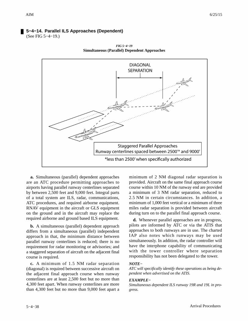
AIM 4/3/14
5−4−38 Arrival Procedures
5−4−14. Parallel ILS Approaches (Dependent) (See FIG 5−4−19.)
FIG 5−4−19
Simultaneous (Parallel) Dependent Approaches
a. Simultaneous (parallel) dependent approachesare an ATC procedure permitting approaches toairports having parallel runway centerlines separatedby between 2,500 feet and 9,000 feet. Integral partsof a total system are ILS, radar, communications,ATC procedures, and required airborne equipment.RNAV equipment in the aircraft or GLS equipmenton the ground and in the aircraft may replace therequired airborne and ground based ILS equipment.
b. A simultaneous (parallel) dependent approachdiffers from a simultaneous (parallel) independentapproach in that, the minimum distance betweenparallel runway centerlines is reduced; there is norequirement for radar monitoring or advisories; anda staggered separation of aircraft on the adjacent finalcourse is required.
c. A minimum of 1.5 NM radar separation(diagonal) is required between successive aircraft onthe adjacent final approach course when runwaycenterlines are at least 2,500 feet but no more than4,300 feet apart. When runway centerlines are morethan 4,300 feet but no more than 9,000 feet apart a
minimum of 2 NM diagonal radar separation isprovided. Aircraft on the same final approach coursecourse within 10 NM of the runway end are provideda minimum of 3 NM radar separation, reduced to2.5 NM in certain circumstances. In addition, aminimum of 1,000 feet vertical or a minimum of threemiles radar separation is provided between aircraftduring turn on to the parallel final approach course.
d. Whenever parallel approaches are in progress,pilots are informed by ATC or via the ATIS thatapproaches to both runways are in use. The chartedIAP also notes which runways may be usedsimultaneously. In addition, the radar controller willhave the interphone capability of communicatingwith the tower controller where separationresponsibility has not been delegated to the tower.
NOTE−ATC will specifically identify these operations as being de-pendent when advertised on the ATIS.
EXAMPLE−Simultaneous dependent ILS runway 19R and 19L in pro-gress.
3/15/077110.65R CHG 2AIM 6/25/15
AIM4/3/14
5−4−39Arrival Procedures
e. At certain airports, simultaneous (parallel) de-pendent approaches are permitted to runways spacedless than 2500 feet apart. In this case, ATC will stag-ger aircraft on the parallel approaches with theleaders always arriving on the same runway. Thetrailing aircraft is permitted diagonal separation ofnot less than 1.5 NM, instead of the single runwayseparation normally utilized for runways spaced lessthan 2500 feet apart. For wake turbulence mitigationreasons: a) 1.5 NM spacing is only permitted whenthe leader is either in the large or small wake turbu-lence category, and b) all aircraft must descend on theglideslope from the altitude at which they werecleared for the approach during these operations.When 1.5 NM reduced separation is authorized, the
IAP briefing strip which indicates that simultaneousoperations require the use of vertical guidance andthat the pilot should maintain last assigned altitudeuntil intercepting the glideslope. No special pilottraining is required to participate in these operations.
NOTE−Either simultaneous dependent ILS approaches or SOIALDA PRM and ILS PRM approaches may be conducted tothese runways depending on weather conditions and trafficvolume. Pilots should use caution so as not to confuse theseoperations. Use SOIA procedures only when the ATIS ad-vertises PRM approaches are in use, refer to AIMparagraph 5-4-16. SFO is the only airport where both pro-cedures are presently conducted.
7/24/14 AIM
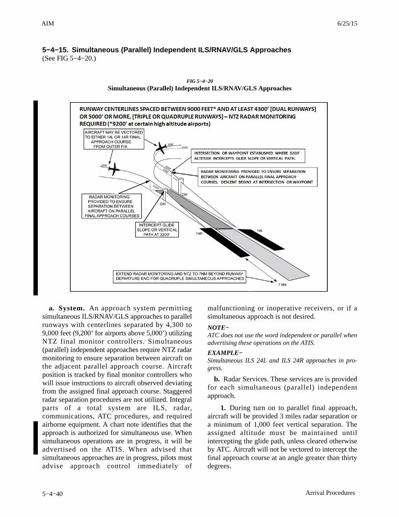
AIM 4/3/14
5−4−40 Arrival Procedures
5−4−15. Simultaneous (Parallel) Independent ILS/RNAV/GLS Approaches(See FIG 5−4−20.)
FIG 5−4−20
Simultaneous (Parallel) Independent ILS/RNAV/GLS Approaches
a. System. An approach system permittingsimultaneous ILS/RNAV/GLS approaches to parallelrunways with centerlines separated by 4,300 to9,000 feet (9,200’ for airports above 5,000’) utilizingNTZ final monitor controllers. Simultaneous(parallel) independent approaches require NTZ radarmonitoring to ensure separation between aircraft onthe adjacent parallel approach course. Aircraftposition is tracked by final monitor controllers whowill issue instructions to aircraft observed deviatingfrom the assigned final approach course. Staggeredradar separation procedures are not utilized. Integralparts of a total system are ILS, radar,communications, ATC procedures, and requiredairborne equipment. A chart note identifies that theapproach is authorized for simultaneous use. Whensimultaneous operations are in progress, it will beadvertised on the ATIS. When advised thatsimultaneous approaches are in progress, pilots mustadvise approach control immediately of
malfunctioning or inoperative receivers, or if asimultaneous approach is not desired.
NOTE−ATC does not use the word independent or parallel whenadvertising these operations on the ATIS.
EXAMPLE−Simultaneous ILS 24L and ILS 24R approaches in pro-gress.
b. Radar Services. These services are is providedfor each simultaneous (parallel) independentapproach.
1. During turn on to parallel final approach,aircraft will be provided 3 miles radar separation ora minimum of 1,000 feet vertical separation. Theassigned altitude must be maintained untilintercepting the glide path, unless cleared otherwiseby ATC. Aircraft will not be vectored to intercept thefinal approach course at an angle greater than thirtydegrees.
3/15/077110.65R CHG 2AIM 6/25/15
AIM4/3/14
5−4−49Arrival Procedures
that, when a pilot receives breakout instructions, he/she assumes that a blundering aircraft is about to orhas penetrated the NTZ and is heading toward his/herapproach course. The pilot must initiate a breakoutas soon as safety allows. While conducting PRM ap-proaches, pilots must maintain an increased sense ofawareness in order to immediately react to an ATC in-struction (breakout) and maneuver as instructed byATC, away from a blundering aircraft.
2. Communications. To help in avoiding com-munication problems caused by stuck microphonesand two parties talking at the same time, two frequen-cies for each runway will be in use during ILS PRMand LDA PRM approach operations, the primarytower frequency and the PRM monitor frequency.The tower controller transmits and receive in a nor-mal fashion on the primary frequency and alsotransmits on the PRM monitor frequency. The monit-or controller’s transmissions override on bothfrequencies. The pilots flying the approach will listento both frequencies but only transmit on the primarytower frequency. If the PRM monitor controller initi-ates a breakout and the primary frequency is blockedby another transmission, the breakout instruction willstill be heard on the PRM monitor frequency.
NOTE−At some airports, the override capability may be on otherthan the tower frequency (KSFO overrides the final radarcontroller frequency). Pilots should carefully review thedual communications requirements on the AAUP prior toaccepting a PRM approach.
3. Breakouts. The probability is extremelylow that an aircraft will “blunder” from its assignedapproach course and enter the NTZ, causing ATC to“breakout” the aircraft approaching on the adjacentILS or LDA course. However, because of the closeproximity of the final approach courses, it is essentialthat pilots follow the ATC breakout instructions pre-cisely and expeditiously. The controller’s “breakout”instructions provide conflict resolution for thethreatened aircraft, with the turn portion of the“breakout” being the single most important elementin achieving maximum protection. A descendingbreakout will only be issued when it is the only con-troller option. In no case will the controller descendan aircraft below the MVA, which will provide at least1,000 feet clearance above obstacles. The pilot is notexpected to exceed 1,000 feet per minute rate of des-cent in the event a descending breakout is issued.
4. Hand-flown Breakouts. The use of theautopilot is encouraged while flying an ILS PRM orLDA PRM approach, but the autopilot must be disen-gaged in the rare event that a breakout is issued.Simulation studies of breakouts have shown that ahand-flown breakout can be initiated consistentlyfaster than a breakout performed using the autopilot.
5. TCAS. The ATC breakout instruction is theprimary means of conflict resolution. TCAS, if in-stalled, provides another form of conflict resolutionin the unlikely event other separation standardswould fail. TCAS is not required to conduct a closelyspaced approach.
The TCAS provides only vertical resolution of air-craft conflicts, while the ATC breakout instructionprovides both vertical and horizontal guidance forconflict resolutions. Pilots should always immedi-ately follow the TCAS Resolution Advisory (RA),whenever it is received. Should a TCAS RA be re-ceived before, during, or after an ATC breakoutinstruction is issued, the pilot should follow the RA,even if it conflicts with the climb/descent portion ofthe breakout maneuver. If following an RA requiresdeviating from an ATC clearance, the pilot must ad-vise ATC as soon as practical. While following anRA, it is extremely important that the pilot alsocomply with the turn portion of the ATC breakout in-struction unless the pilot determines safety to befactor. Adhering to these procedures assures the pilotthat acceptable “breakout” separation margins willalways be provided, even in the face of a normal pro-cedural or system failure.
5−4−17. Simultaneous ConvergingInstrument Approaches
a. ATC may conduct instrument approachessimultaneously to converging runways; i.e., runwayshaving an included angle from 15 to 100 degrees, atairports where a program has been specificallyapproved to do so.
b. The basic concept requires that dedicated,separate standard instrument approach procedures bedeveloped for each converging runway included.These approaches can be identified by the letter “V”in the title; for example, “ILS V Rwy 17(CONVERGING)”. Missed Approach Points mustbe at least 3 miles apart and missed approachprocedures ensure that missed approach protectedairspace does not overlap.
6/25/15 AIM
AIM 4/3/14
5−4−50 Arrival Procedures
c. Other requirements are: radar availability,nonintersecting final approach courses, precisionapproach capability for each runway and, if runwaysintersect, controllers must be able to apply visualseparation as well as intersecting runway separationcriteria. Intersecting runways also require minimumsof at least 700 foot ceilings and 2 miles visibility.Straight in approaches and landings must be made.
d. Whenever simultaneous convergingapproaches are in progress, aircraft will be informedby the controller as soon as feasible after initialcontact or via ATIS. Additionally, the radar controllerwill have direct communications capability with thetower controller where separation responsibility hasnot been delegated to the tower.
5−4−18. RNP AR Instrument ApproachProcedures
These procedures require authorization analogous tothe special authorization required for Category II orIII ILS procedures. Authorization required (AR)procedures are to be conducted by aircrews meetingspecial training requirements in aircraft that meet thespecified performance and functional requirements.
a. Unique characteristics of RNP ARApproaches
1. RNP value. Each published line of minimahas an associated RNP value. The indicated valuedefines the lateral and vertical performancerequirements. A minimum RNP type is documentedas part of the RNP AR authorization for each operatorand may vary depending on aircraft configuration oroperational procedures (e.g., GPS inoperative, use offlight director vice autopilot).
2. Curved path procedures. Some RNPapproaches have a curved path, also called aradius−to−a−fix (RF) leg. Since not all aircraft havethe capability to fly these arcs, pilots are responsiblefor knowing if they can conduct an RNP approach
with an arc or not. Aircraft speeds, winds and bankangles have been taken into consideration in thedevelopment of the procedures.
3. RNP required for extraction or not.Where required, the missed approach procedure mayuse RNP values less than RNP−1. The reliability ofthe navigation system has to be very high in order toconduct these approaches. Operation on theseprocedures generally requires redundant equipment,as no single point of failure can cause loss of bothapproach and missed approach navigation.
4. Non−standard speeds or climb gradients.RNP AR approaches are developed based on standardapproach speeds and a 200 ft/NM climb gradient inthe missed approach. Any exceptions to thesestandards will be indicated on the approachprocedure, and the operator should ensure they cancomply with any published restrictions beforeconducting the operation.
5. Temperature Limits. For aircraft usingbarometric vertical navigation (without temperaturecompensation) to conduct the approach, low andhigh−temperature limits are identified on theprocedure. Cold temperatures reduce the glidepathangle while high temperatures increase the glidepathangle. Aircraft using baro VNAV with temperaturecompensation or aircraft using an alternate means forvertical guidance (e.g., SBAS) may disregard thetemperature restrictions. The charted temperaturelimits are evaluated for the final approach segmentonly. Regardless of charted temperature limits ortemperature compensation by the FMS, the pilot mayneed to manually compensate for cold temperature onminimum altitudes and the decision altitude.
6. Aircraft size. The achieved minimums maybe dependent on aircraft size. Large aircraft mayrequire higher minimums due to gear height and/orwingspan. Approach procedure charts will beannotated with applicable aircraft size restrictions.
3/15/077110.65R CHG 2AIM 6/25/15

AIM4/3/14
7−1−3Meteorology
c. Other Sources of Weather Information
1. Telephone Information Briefing Service(TIBS) (FSS); and in Alaska, Transcribed WeatherBroadcast (TWEB) locations, and telephone accessto the TWEB (TEL−TWEB) provide continuouslyupdated recorded weather information for short orlocal flights. Separate paragraphs in this section giveadditional information regarding these services.
REFERENCE−AIM, Telephone Information Briefing Service (TIBS), Paragraph 7−1−8.AIM, Transcribed Weather Broadcast (TWEB) (Alaska Only),Paragraph 7−1−9.
2. Weather and aeronautical information arealso available from numerous private industrysources on an individual or contract pay basis.Information on how to obtain this service should beavailable from local pilot organizations.
3. Pilots can access the Direct User AccessTerminal System (DUATS) and Lockheed MartinFlight Services with a current medical certificate viathe internet. Pilots can receive preflight weather dataand file domestic VFR and IFR flight plans. Thefollowing are the contract DUATS vendors:
Computer Sciences Corporation (CSC) Internet Access: http://www.duats.comFor customer service: (800) 345−3828 Data Transformation Corporation (DTC)Internet Access: http://www.duat.comFor customer service: (800) 243−3828 Lockheed Martin Flight ServicesInternet Access: http://www.1800wxbrief.comFor customer service: (866) 936−6826
d. Inflight weather information is available fromany FSS within radio range. The common frequencyfor all FSSs is 122.2. Discrete frequencies forindividual stations are listed in the A/FD.
1. Information on In-Flight Weather broadcasts.
REFERENCE−AIM, Inflight Weather Broadcasts, Paragraph 7−1−10.
2. En Route Flight Advisory Service (EFAS) isprovided to serve the nonroutine weather needs ofpilots in flight.
REFERENCE−AIM, En Route Flight Advisory Service (EFAS), Paragraph 7−1−5, givesdetails on this service.
7−1−3. Use of Aviation Weather Products
a. Air carriers and operators certificated under theprovisions of 14 CFR Part 119 are required to use theaeronautical weather information systems defined inthe Operations Specifications issued to that certifi-cate holder by the FAA. These systems may utilizebasic FAA/National Weather Service (NWS) weatherservices, contractor− or operator−proprietary weath-er services and/or Enhanced Weather InformationSystem (EWINS) when approved in the OperationsSpecifications. As an integral part of this systemapproval, the procedures for collecting, producingand disseminating aeronautical weather information,as well as the crew member and dispatcher training tosupport the use of system weather products, must beaccepted or approved.
b. Operators not certificated under the provisionsof 14 CFR Part 119 are encouraged to use FAA/NWSproducts through Flight Service Stations, Direct UserAccess Terminal System (DUATS), LockheedMartin Flight Services, and/or Flight InformationServices−Broadcast (FIS−B).
c. The suite of available aviation weather producttypes is expanding, with the development of newsensor systems, algorithms and forecast models. TheFAA and NWS, supported by various weatherresearch laboratories and corporations under contractto the Government, develop and implement newaviation weather product types. The FAA’s NextGenAviation Weather Research Program (AWRP)facilitates collaboration between the NWS, the FAA,and various industry and research representatives.This collaboration ensures that user needs andtechnical readiness requirements are met beforeexperimental products mature to operational applica-tion.
d. The AWRP manages the transfer of aviationweather R&D to operational use through technicalreview panels and conducting safety assessments toensure that newly developed aviation weatherproducts meet regulatory requirements and enhancesafety.
e. The AWRP review and decision−makingprocess applies criteria to weather products at variousstages . The stages are composed of the following:
1. Sponsorship of user needs.
6/25/15 AIM

AIM 4/3/14
7−1−4 Meteorology
2. R & D and controlled testing.
3. Experimental application.
4. Operational application.
f. Pilots and operators should be aware thatweather services provided by entities other than FAA,NWS or their contractors (such as the DUAT/DUATSand Lockheed Martin Flight Services) may not meetFAA/NWS quality control standards. Hence,operators and pilots contemplating using suchservices should request and/or review an appropriatedescription of services and provider disclosure. Thisshould include, but is not limited to, the type ofweather product (e.g., current weather or forecastweather), the currency of the product (i.e., productissue and valid times), and the relevance of theproduct. Pilots and operators should be cautiouswhen using unfamiliar products, or products notsupported by FAA/NWS technical specifications.
NOTE−When in doubt, consult with a FAA Flight Service StationSpecialist.
g. In addition, pilots and operators should beaware there are weather services and productsavailable from government organizations beyond thescope of the AWRP process mentioned earlier in thissection. For example, governmental agencies such asthe NWS and the Aviation Weather Center (AWC), orresearch organizations such as the National Centerfor Atmospheric Research (NCAR) display weather“model data” and “experimental” products whichrequire training and/or expertise to properly interpretand use. These products are developmental proto-types that are subject to ongoing research and canchange without notice. Therefore, some data ondisplay by government organizations, or governmentdata on display by independent organizations may beunsuitable for flight planning purposes. Operatorsand pilots contemplating using such services shouldrequest and/or review an appropriate description ofservices and provider disclosure. This should include,but is not limited to, the type of weather product (forexample, current weather or forecast weather), thecurrency of the product (i.e., product issue and validtimes), and the relevance of the product. Pilots andoperators should be cautious when using unfamiliarweather products.
NOTE−When in doubt, consult with a FAA Flight Service StationSpecialist.
h. With increased access to weather products viathe public Internet, the aviation community hasaccess to an over whelming amount of weatherinformation and data that support self-briefing. FAAAC 00-45 (current edition) describes the weatherproducts distributed by the NWS. Pilots andoperators using the public Internet to access weatherfrom a third party vendor should request and/orreview an appropriate description of services andprovider disclosure. This should include, but is notlimited to, the type of weather product (for example,current weather or forecast weather), the currency ofthe product (i.e., product issue and valid times), andthe relevance of the product. Pilots and operatorsshould be cautious when using unfamiliar weatherproducts and when in doubt, consult with a FlightService Specialist.
i. The development of new weather products,coupled with the termination of some legacy textualand graphical products may create confusion betweenregulatory requirements and the new products. Allflight−related, aviation weather decisions must bebased on all available pertinent weather products. Asevery flight is unique and the weather conditions forthat flight vary hour by hour, day to day, multipleweather products may be necessary to meet aviationweather regulatory requirements. Many new weatherproducts now have a Precautionary Use Statementthat details the proper use or application of thespecific product.
j. The FAA has identified three distinct types ofweather information available to pilots and operators.
1. Observations. Raw weather data collectedby some type of sensor suite including surface andairborne observations, radar, lightning, satelliteimagery, and profilers.
2. Analysis. Enhanced depiction and/or inter-pretation of observed weather data.
3. Forecasts. Predictions of the developmentand/or movement of weather phenomena based onmeteorological observations and various mathemat-ical models.
k. Not all sources of aviation weather informationare able to provide all three types of weatherinformation. The FAA has determined that operatorsand pilots may utilize the following approved sourcesof aviation weather information:
1. Federal Government. The FAA and NWScollect raw weather data, analyze the observations,
3/15/077110.65R CHG 2AIM 7/24/14
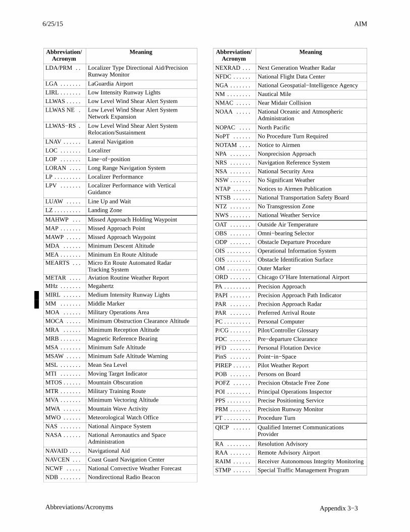
AIM4/3/14
Appendix 3−3Abbreviations/Acronyms
Abbreviation/Acronym
Meaning
LDA/PRM . . Localizer Type Directional Aid/PrecisionRunway Monitor
LGA . . . . . . . LaGuardia Airport
LIRL . . . . . . . Low Intensity Runway Lights
LLWAS . . . . . Low Level Wind Shear Alert System
LLWAS NE . Low Level Wind Shear Alert SystemNetwork Expansion
LLWAS−RS . Low Level Wind Shear Alert SystemRelocation/Sustainment
LNAV . . . . . . Lateral Navigation
LOC . . . . . . . Localizer
LOP . . . . . . . Line−of−position
LORAN . . . . Long Range Navigation System
LP . . . . . . . . . Localizer Performance
LPV . . . . . . . Localizer Performance with VerticalGuidance
LUAW . . . . . Line Up and Wait
LZ . . . . . . . . . Landing Zone
MAHWP . . . Missed Approach Holding Waypoint
MAP . . . . . . . Missed Approach Point
MAWP . . . . . Missed Approach Waypoint
MDA . . . . . . Minimum Descent Altitude
MEA . . . . . . . Minimum En Route AltitudeMEARTS . . . Micro En Route Automated Radar
Tracking SystemMETAR . . . . Aviation Routine Weather ReportMHz . . . . . . . Megahertz
MIRL . . . . . . Medium Intensity Runway Lights
MM . . . . . . . Middle Marker
MOA . . . . . . Military Operations Area
MOCA . . . . . Minimum Obstruction Clearance Altitude
MRA . . . . . . Minimum Reception Altitude
MRB . . . . . . . Magnetic Reference Bearing
MSA . . . . . . . Minimum Safe Altitude
MSAW . . . . . Minimum Safe Altitude Warning
MSL . . . . . . . Mean Sea Level
MTI . . . . . . . Moving Target Indicator
MTOS . . . . . . Mountain Obscuration
MTR . . . . . . . Military Training Route
MVA . . . . . . . Minimum Vectoring Altitude
MWA . . . . . . Mountain Wave Activity
MWO . . . . . . Meteorological Watch Office
NAS . . . . . . . National Airspace System
NASA . . . . . . National Aeronautics and SpaceAdministration
NAVAID . . . . Navigational Aid
NAVCEN . . . Coast Guard Navigation Center
NCWF . . . . . National Convective Weather Forecast
NDB . . . . . . . Nondirectional Radio Beacon
Abbreviation/Acronym
Meaning
NEXRAD . . . Next Generation Weather Radar
NFDC . . . . . . National Flight Data Center
NGA . . . . . . . National Geospatial−Intelligence Agency
NM . . . . . . . . Nautical Mile
NMAC . . . . . Near Midair Collision
NOAA . . . . . National Oceanic and AtmosphericAdministration
NOPAC . . . . North Pacific
NoPT . . . . . . No Procedure Turn Required
NOTAM . . . . Notice to Airmen
NPA . . . . . . . Nonprecision Approach
NRS . . . . . . . Navigation Reference System
NSA . . . . . . . National Security Area
NSW . . . . . . . No Significant Weather
NTAP . . . . . . Notices to Airmen Publication
NTSB . . . . . . National Transportation Safety Board
NTZ . . . . . . . No Transgression Zone
NWS . . . . . . . National Weather Service
OAT . . . . . . . Outside Air Temperature
OBS . . . . . . . Omni−bearing Selector
ODP . . . . . . . Obstacle Departure Procedure
OIS . . . . . . . . Operational Information System
OIS . . . . . . . . Obstacle Identification Surface
OM . . . . . . . . Outer Marker
ORD . . . . . . . Chicago O’Hare International Airport
PA . . . . . . . . . Precision Approach
PAPI . . . . . . . Precision Approach Path Indicator
PAR . . . . . . . Precision Approach Radar
PAR . . . . . . . Preferred Arrival Route
PC . . . . . . . . . Personal Computer
P/CG . . . . . . . Pilot/Controller Glossary
PDC . . . . . . . Pre−departure Clearance
PFD . . . . . . . Personal Flotation Device
PinS . . . . . . . Point−in−Space
PIREP . . . . . . Pilot Weather Report
POB . . . . . . . Persons on Board
POFZ . . . . . . Precision Obstacle Free Zone
POI . . . . . . . . Principal Operations Inspector
PPS . . . . . . . . Precise Positioning Service
PRM . . . . . . . Precision Runway Monitor
PT . . . . . . . . . Procedure Turn
QICP . . . . . . Qualified Internet CommunicationsProvider
RA . . . . . . . . Resolution Advisory
RAA . . . . . . . Remote Advisory Airport
RAIM . . . . . . Receiver Autonomous Integrity Monitoring
STMP . . . . . . Special Traffic Management Program
6/25/15 AIM
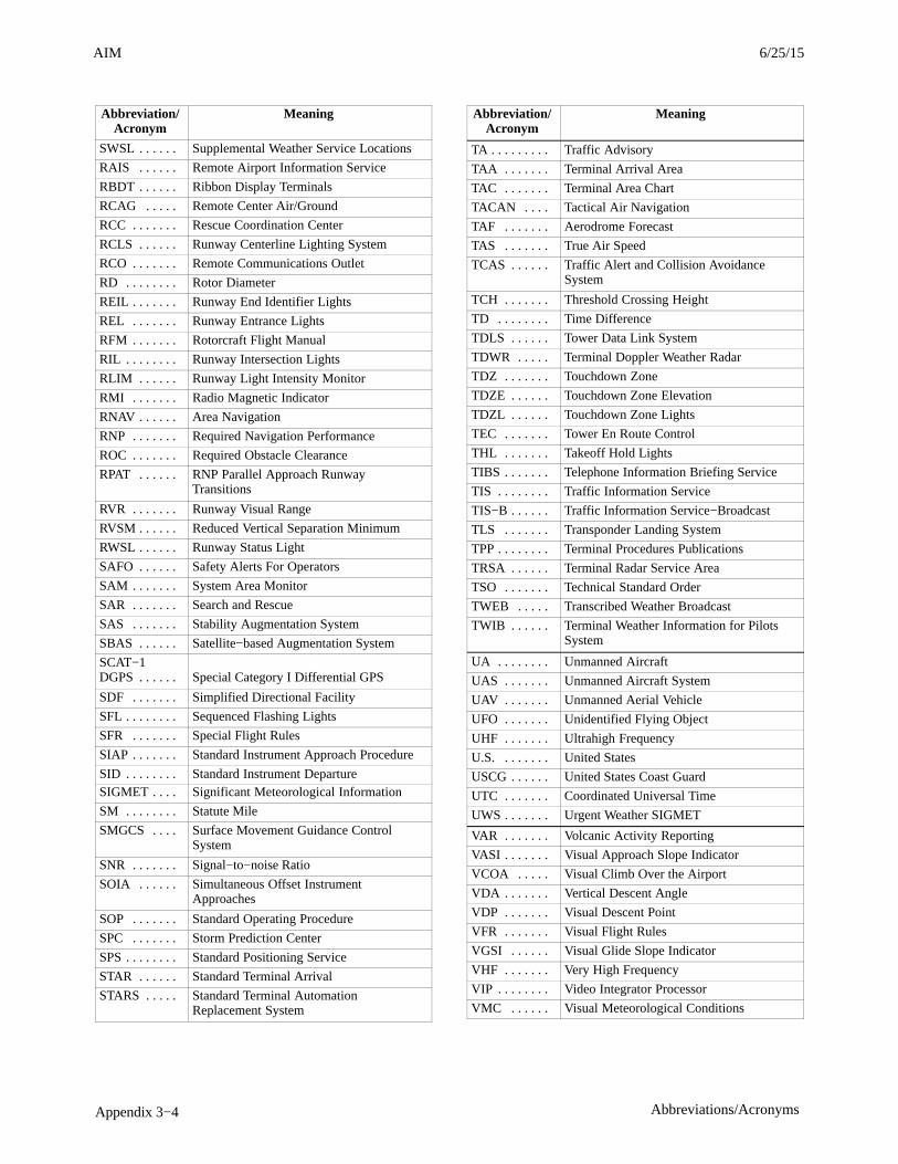
AIM 4/3/14
Appendix 3−4 Abbreviations/Acronyms
Abbreviation/Acronym
Meaning
SWSL . . . . . . Supplemental Weather Service Locations
RAIS . . . . . . Remote Airport Information Service
RBDT . . . . . . Ribbon Display Terminals
RCAG . . . . . Remote Center Air/Ground
RCC . . . . . . . Rescue Coordination Center
RCLS . . . . . . Runway Centerline Lighting System
RCO . . . . . . . Remote Communications Outlet
RD . . . . . . . . Rotor Diameter
REIL . . . . . . . Runway End Identifier Lights
REL . . . . . . . Runway Entrance Lights
RFM . . . . . . . Rotorcraft Flight Manual
RIL . . . . . . . . Runway Intersection Lights
RLIM . . . . . . Runway Light Intensity Monitor
RMI . . . . . . . Radio Magnetic Indicator
RNAV . . . . . . Area Navigation
RNP . . . . . . . Required Navigation Performance
ROC . . . . . . . Required Obstacle Clearance
RPAT . . . . . . RNP Parallel Approach RunwayTransitions
RVR . . . . . . . Runway Visual Range
RVSM . . . . . . Reduced Vertical Separation Minimum
RWSL . . . . . . Runway Status Light
SAFO . . . . . . Safety Alerts For Operators
SAM . . . . . . . System Area Monitor
SAR . . . . . . . Search and Rescue
SAS . . . . . . . Stability Augmentation System
SBAS . . . . . . Satellite−based Augmentation System
SCAT−1DGPS . . . . . . Special Category I Differential GPS
SDF . . . . . . . Simplified Directional Facility
SFL . . . . . . . . Sequenced Flashing Lights
SFR . . . . . . . Special Flight Rules
SIAP . . . . . . . Standard Instrument Approach Procedure
SID . . . . . . . . Standard Instrument DepartureSIGMET . . . . Significant Meteorological Information
SM . . . . . . . . Statute Mile
SMGCS . . . . Surface Movement Guidance ControlSystem
SNR . . . . . . . Signal−to−noise Ratio
SOIA . . . . . . Simultaneous Offset InstrumentApproaches
SOP . . . . . . . Standard Operating Procedure
SPC . . . . . . . Storm Prediction Center
SPS . . . . . . . . Standard Positioning Service
STAR . . . . . . Standard Terminal Arrival
STARS . . . . . Standard Terminal AutomationReplacement System
Abbreviation/Acronym
Meaning
TA . . . . . . . . . Traffic Advisory
TAA . . . . . . . Terminal Arrival Area
TAC . . . . . . . Terminal Area Chart
TACAN . . . . Tactical Air Navigation
TAF . . . . . . . Aerodrome Forecast
TAS . . . . . . . True Air Speed
TCAS . . . . . . Traffic Alert and Collision AvoidanceSystem
TCH . . . . . . . Threshold Crossing Height
TD . . . . . . . . Time Difference
TDLS . . . . . . Tower Data Link System
TDWR . . . . . Terminal Doppler Weather Radar
TDZ . . . . . . . Touchdown Zone
TDZE . . . . . . Touchdown Zone Elevation
TDZL . . . . . . Touchdown Zone Lights
TEC . . . . . . . Tower En Route Control
THL . . . . . . . Takeoff Hold Lights
TIBS . . . . . . . Telephone Information Briefing Service
TIS . . . . . . . . Traffic Information Service
TIS−B . . . . . . Traffic Information Service−Broadcast
TLS . . . . . . . Transponder Landing System
TPP . . . . . . . . Terminal Procedures Publications
TRSA . . . . . . Terminal Radar Service Area
TSO . . . . . . . Technical Standard Order
TWEB . . . . . Transcribed Weather Broadcast
TWIB . . . . . . Terminal Weather Information for PilotsSystem
UA . . . . . . . . Unmanned Aircraft
UAS . . . . . . . Unmanned Aircraft System
UAV . . . . . . . Unmanned Aerial Vehicle
UFO . . . . . . . Unidentified Flying Object
UHF . . . . . . . Ultrahigh Frequency
U.S. . . . . . . . United States
USCG . . . . . . United States Coast Guard
UTC . . . . . . . Coordinated Universal Time
UWS . . . . . . . Urgent Weather SIGMET
VAR . . . . . . . Volcanic Activity Reporting
VASI . . . . . . . Visual Approach Slope Indicator
VCOA . . . . . Visual Climb Over the Airport
VDA . . . . . . . Vertical Descent Angle
VDP . . . . . . . Visual Descent Point
VFR . . . . . . . Visual Flight Rules
VGSI . . . . . . Visual Glide Slope Indicator
VHF . . . . . . . Very High Frequency
VIP . . . . . . . . Video Integrator Processor
VMC . . . . . . Visual Meteorological Conditions
3/15/077110.65R CHG 2AIM 6/25/15
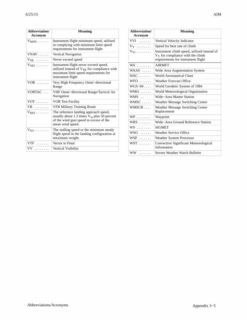
AIM4/3/14
Appendix 3−5Abbreviations/Acronyms
Abbreviation/Acronym
Meaning
VMINI . . . . . . Instrument flight minimum speed, utilizedin complying with minimum limit speedrequirements for instrument flight
VNAV . . . . . . Vertical Navigation
VNE . . . . . . . Never exceed speed
VNEI . . . . . . . Instrument flight never exceed speed,utilized instead of VNE for compliance withmaximum limit speed requirements forinstrument flight
VOR . . . . . . . Very High Frequency Omni−directionalRange
VORTAC . . . VHF Omni−directional Range/Tactical AirNavigation
VOT . . . . . . . VOR Test Facility
VR . . . . . . . . VFR Military Training Route
VREF . . . . . . . The reference landing approach speed,usually about 1.3 times Vso plus 50 percentof the wind gust speed in excess of themean wind speed.
VSO . . . . . . . . The stalling speed or the minimum steadyflight speed in the landing configuration atmaximum weight.
VTF . . . . . . . Vector to Final
VV . . . . . . . . Vertical Visibility
Abbreviation/Acronym
Meaning
VVI . . . . . . . Vertical Velocity Indicator
VY . . . . . . . . Speed for best rate of climb
VYI . . . . . . . . Instrument climb speed, utilized instead ofVY for compliance with the climbrequirements for instrument flight
WA . . . . . . . . AIRMET
WAAS . . . . . Wide Area Augmentation System
WAC . . . . . . . World Aeronautical Chart
WFO . . . . . . . Weather Forecast Office
WGS−84 . . . . World Geodetic System of 1984
WMO . . . . . . World Meteorological Organization
WMS . . Wide−Area Master Station
WMSC . . . . . Weather Message Switching Center
WMSCR . . . . Weather Message Switching CenterReplacement
WP . . . . . . . . Waypoint
WRS . . . . . . . Wide−Area Ground Reference Station
WS . . . . . . . . SIGMET
WSO . . . . . . Weather Service Office
WSP . . . . . . . Weather System Processor
WST . . . . . . . Convective Significant MeteorologicalInformation
WW . . . . . . . Severe Weather Watch Bulletin
6/25/15 AIM

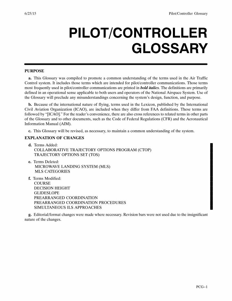
Pilot/Controller Glossary6/25/15
PCG−1
PILOT/CONTROLLERGLOSSARY
PURPOSE
a. This Glossary was compiled to promote a common understanding of the terms used in the Air TrafficControl system. It includes those terms which are intended for pilot/controller communications. Those termsmost frequently used in pilot/controller communications are printed in bold italics. The definitions are primarilydefined in an operational sense applicable to both users and operators of the National Airspace System. Use ofthe Glossary will preclude any misunderstandings concerning the system’s design, function, and purpose.
b. Because of the international nature of flying, terms used in the Lexicon, published by the InternationalCivil Aviation Organization (ICAO), are included when they differ from FAA definitions. These terms arefollowed by “[ICAO].” For the reader’s convenience, there are also cross references to related terms in other partsof the Glossary and to other documents, such as the Code of Federal Regulations (CFR) and the AeronauticalInformation Manual (AIM).
c. This Glossary will be revised, as necessary, to maintain a common understanding of the system.
EXPLANATION OF CHANGES
d. Terms Added:COLLABORATIVE TRAJECTORY OPTIONS PROGRAM (CTOP)TRAJECTORY OPTIONS SET (TOS)
e. Terms Deleted:MICROWAVE LANDING SYSTEM (MLS)MLS CATEGORIES
f. Terms Modified:COURSEDECISION HEIGHTGLIDESLOPEPREARRANGED COORDINATIONPREARRANGED COORDINATION PROCEDURESSIMULTANEOUS ILS APPROACHES
g. Editorial/format changes were made where necessary. Revision bars were not used due to the insignificantnature of the changes.


6/25/15 Pilot/Controller Glossary
Page Control Chart
PAGE CONTROL CHART
REMOVE PAGES DATED INSERT PAGES DATED
PCG−1 . . . . . . . . . . . . . . . . . . . . . . . . . . . . . . 1/8/15 PCG−1 . . . . . . . . . . . . . . . . . . . . . . . . . . . . . 6/25/15
PCG C−3 . . . . . . . . . . . . . . . . . . . . . . . . . . . . 7/24/14 PCG C−3 . . . . . . . . . . . . . . . . . . . . . . . . . . . 7/24/14
PCG C−4 through PCG C−9 . . . . . . . . . . . . . 1/8/15 PCG C−4 through PCG C−9 . . . . . . . . . . . . 6/25/15
PCG D−1 . . . . . . . . . . . . . . . . . . . . . . . . . . . . 7/24/14 PCG D−1 . . . . . . . . . . . . . . . . . . . . . . . . . . . 6/25/15
PCG D−2 . . . . . . . . . . . . . . . . . . . . . . . . . . . . 1/8/15 PCG D−2 . . . . . . . . . . . . . . . . . . . . . . . . . . . 1/8/15
PCG G−1 . . . . . . . . . . . . . . . . . . . . . . . . . . . . 7/24/14 PCG G−1 . . . . . . . . . . . . . . . . . . . . . . . . . . . 6/25/15
PCG G−2 . . . . . . . . . . . . . . . . . . . . . . . . . . . . 7/24/14 PCG G−2 . . . . . . . . . . . . . . . . . . . . . . . . . . . 7/24/14
PCG M−1 . . . . . . . . . . . . . . . . . . . . . . . . . . . . 7/24/14 PCG M−1 . . . . . . . . . . . . . . . . . . . . . . . . . . 7/24/14
PCG M−2 through PCG M−6 . . . . . . . . . . . . 7/24/14 PCG M−2 through PCG M−6 . . . . . . . . . . . 6/25/15
PCG P−1 . . . . . . . . . . . . . . . . . . . . . . . . . . . . . 7/24/14 PCG P−1 . . . . . . . . . . . . . . . . . . . . . . . . . . . . 7/24/14
PCG P−2 . . . . . . . . . . . . . . . . . . . . . . . . . . . . . 7/24/14 PCG P−2 . . . . . . . . . . . . . . . . . . . . . . . . . . . . 6/25/15
PCG S−3 . . . . . . . . . . . . . . . . . . . . . . . . . . . . . 7/24/14 PCG S−3 . . . . . . . . . . . . . . . . . . . . . . . . . . . . 7/24/14
PCG S−4 and PCG S−5 . . . . . . . . . . . . . . . . . 7/24/14 PCG S−4 and PCG S−5 . . . . . . . . . . . . . . . . 6/25/15
PCG S−6 . . . . . . . . . . . . . . . . . . . . . . . . . . . . . 7/24/14 PCG S−6 . . . . . . . . . . . . . . . . . . . . . . . . . . . . 7/24/14
PCG T−3 through PCG T−8 . . . . . . . . . . . . . 7/24/14 PCG T−3 through PCG T−8 . . . . . . . . . . . . 6/25/15

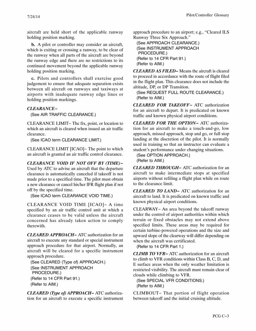
Pilot/Controller Glossary7/24/14
PCG C−3
aircraft are held short of the applicable runwayholding position marking.
b. A pilot or controller may consider an aircraft,which is exiting or crossing a runway, to be clear ofthe runway when all parts of the aircraft are beyondthe runway edge and there are no restrictions to itscontinued movement beyond the applicable runwayholding position marking.
c. Pilots and controllers shall exercise goodjudgement to ensure that adequate separation existsbetween all aircraft on runways and taxiways atairports with inadequate runway edge lines orholding position markings.
CLEARANCE−(See AIR TRAFFIC CLEARANCE.)
CLEARANCE LIMIT− The fix, point, or location towhich an aircraft is cleared when issued an air trafficclearance.
(See ICAO term CLEARANCE LIMIT.)
CLEARANCE LIMIT [ICAO]− The point to whichan aircraft is granted an air traffic control clearance.
CLEARANCE VOID IF NOT OFF BY (TIME)−Used by ATC to advise an aircraft that the departureclearance is automatically canceled if takeoff is notmade prior to a specified time. The pilot must obtaina new clearance or cancel his/her IFR flight plan if notoff by the specified time.
(See ICAO term CLEARANCE VOID TIME.)
CLEARANCE VOID TIME [ICAO]− A timespecified by an air traffic control unit at which aclearance ceases to be valid unless the aircraftconcerned has already taken action to complytherewith.
CLEARED APPROACH− ATC authorization for anaircraft to execute any standard or special instrumentapproach procedure for that airport. Normally, anaircraft will be cleared for a specific instrumentapproach procedure.
(See CLEARED (Type of) APPROACH.)(See INSTRUMENT APPROACHPROCEDURE.)
(Refer to 14 CFR Part 91.)(Refer to AIM.)
CLEARED (Type of) APPROACH− ATC authoriza-tion for an aircraft to execute a specific instrument
approach procedure to an airport; e.g., “Cleared ILSRunway Three Six Approach.”
(See APPROACH CLEARANCE.)(See INSTRUMENT APPROACHPROCEDURE.)
(Refer to 14 CFR Part 91.)(Refer to AIM.)
CLEARED AS FILED− Means the aircraft is clearedto proceed in accordance with the route of flight filedin the flight plan. This clearance does not include thealtitude, DP, or DP Transition.
(See REQUEST FULL ROUTE CLEARANCE.)(Refer to AIM.)
CLEARED FOR TAKEOFF− ATC authorizationfor an aircraft to depart. It is predicated on knowntraffic and known physical airport conditions.
CLEARED FOR THE OPTION− ATC authoriza-tion for an aircraft to make a touch-and-go, lowapproach, missed approach, stop and go, or full stoplanding at the discretion of the pilot. It is normallyused in training so that an instructor can evaluate astudent’s performance under changing situations.
(See OPTION APPROACH.)(Refer to AIM.)
CLEARED THROUGH− ATC authorization for anaircraft to make intermediate stops at specifiedairports without refiling a flight plan while en routeto the clearance limit.
CLEARED TO LAND− ATC authorization for anaircraft to land. It is predicated on known traffic andknown physical airport conditions.
CLEARWAY− An area beyond the takeoff runwayunder the control of airport authorities within whichterrain or fixed obstacles may not extend abovespecified limits. These areas may be required forcertain turbine-powered operations and the size andupward slope of the clearway will differ depending onwhen the aircraft was certificated.
(Refer to 14 CFR Part 1.)
CLIMB TO VFR− ATC authorization for an aircraftto climb to VFR conditions within Class B, C, D, andE surface areas when the only weather limitation isrestricted visibility. The aircraft must remain clear ofclouds while climbing to VFR.
(See SPECIAL VFR CONDITIONS.)(Refer to AIM.)
CLIMBOUT− That portion of flight operationbetween takeoff and the initial cruising altitude.
Pilot/Controller Glossary 7/24/14
PCG C−4
CLIMB VIA– An abbreviated ATC clearance thatrequires compliance with the procedure lateral path,associated speed restrictions, and altitude restrictionsalong the cleared route or procedure.
CLOSE PARALLEL RUNWAYS− Two parallelrunways whose extended centerlines are separated byless than 4,300 feet and at least 3000 feet (750 feet forSOIA operations) that are authorized to conductsimultaneous independent approach operations.PRM and simultaneous close parallel appear inapproach title. Dual communications, special pilottraining, an Attention All Users Page (AAUP), NTZmonitoring by displays that have aural and visualalerting algorithms are required. A high update ratesurveillance sensor is required for certain runway orapproach course spacing.
CLOSED RUNWAY− A runway that is unusable foraircraft operations. Only the airport management/military operations office can close a runway.
CLOSED TRAFFIC− Successive operations involv-ing takeoffs and landings or low approaches wherethe aircraft does not exit the traffic pattern.
CLOUD− A cloud is a visible accumulation ofminute water droplets and/or ice particles in theatmosphere above the Earth’s surface. Cloud differsfrom ground fog, fog, or ice fog only in that the latterare, by definition, in contact with the Earth’s surface.
CLT−(See CALCULATED LANDING TIME.)
CLUTTER− In radar operations, clutter refers to thereception and visual display of radar returns causedby precipitation, chaff, terrain, numerous aircrafttargets, or other phenomena. Such returns may limitor preclude ATC from providing services based onradar.
(See CHAFF.)
(See GROUND CLUTTER.)
(See PRECIPITATION.)
(See TARGET.)
(See ICAO term RADAR CLUTTER.)
CMNPS−(See CANADIAN MINIMUM NAVIGATIONPERFORMANCE SPECIFICATION AIRSPACE.)
COASTAL FIX− A navigation aid or intersectionwhere an aircraft transitions between the domesticroute structure and the oceanic route structure.
CODES− The number assigned to a particularmultiple pulse reply signal transmitted by atransponder.
(See DISCRETE CODE.)
COLLABORATIVE TRAJECTORY OPTIONSPROGRAM (CTOP)- CTOP is a traffic managementprogram administered by the Air Traffic ControlSystem Command Center (ATCSCC) that managesdemand through constrained airspace, while consid-ering operator preference with regard to both routeand delay as defined in a Trajectory Options Set(TOS).
COMBINED CENTER-RAPCON− An air trafficfacility which combines the functions of an ARTCCand a radar approach control facility.
(See AIR ROUTE TRAFFIC CONTROLCENTER.)
(See RADAR APPROACH CONTROLFACILITY.)
COMMON POINT− A significant point over whichtwo or more aircraft will report passing or havereported passing before proceeding on the same ordiverging tracks. To establish/maintain longitudinalseparation, a controller may determine a commonpoint not originally in the aircraft’s flight plan andthen clear the aircraft to fly over the point.
(See SIGNIFICANT POINT.)
COMMON PORTION−(See COMMON ROUTE.)
COMMON ROUTE− That segment of a NorthAmerican Route between the inland navigationfacility and the coastal fix.
OR
COMMON ROUTE− Typically the portion of aRNAV STAR between the en route transition endpoint and the runway transition start point; however,the common route may only consist of a single pointthat joins the en route and runway transitions.
COMMON TRAFFIC ADVISORY FREQUENCY(CTAF)− A frequency designed for the purpose ofcarrying out airport advisory practices whileoperating to or from an airport without an operating
Pilot/Controller Glossary 6/25/15
Pilot/Controller Glossary7/24/14
PCG C−5
control tower. The CTAF may be a UNICOM,Multicom, FSS, or tower frequency and is identifiedin appropriate aeronautical publications.
(See DESIGNATED COMMON TRAFFICADVISORY FREQUENCY (CTAF) AREA.)
(Refer to AC 90-42, Traffic Advisory Practices atAirports Without Operating Control Towers.)
COMPASS LOCATOR− A low power, low ormedium frequency (L/MF) radio beacon installed atthe site of the outer or middle marker of an instrumentlanding system (ILS). It can be used for navigation atdistances of approximately 15 miles or as authorizedin the approach procedure.
a. Outer Compass Locator (LOM)− A compasslocator installed at the site of the outer marker of aninstrument landing system.
(See OUTER MARKER.)
b. Middle Compass Locator (LMM)− A compasslocator installed at the site of the middle marker of aninstrument landing system.
(See MIDDLE MARKER.)(See ICAO term LOCATOR.)
COMPASS ROSE− A circle, graduated in degrees,printed on some charts or marked on the ground at anairport. It is used as a reference to either true ormagnetic direction.
COMPLY WITH RESTRICTIONS− An ATCinstruction that requires an aircraft being vectoredback onto an arrival or departure procedure to complywith all altitude and/or speed restrictions depicted onthe procedure. This term may be used in lieu ofrepeating each remaining restriction that appears onthe procedure.
COMPOSITE FLIGHT PLAN− A flight plan whichspecifies VFR operation for one portion of flight andIFR for another portion. It is used primarily inmilitary operations.
(Refer to AIM.)
COMPOSITE ROUTE SYSTEM− An organizedoceanic route structure, incorporating reduced lateralspacing between routes, in which compositeseparation is authorized.
COMPOSITE SEPARATION− A method of separat-ing aircraft in a composite route system where, bymanagement of route and altitude assignments, acombination of half the lateral minimum specified for
the area concerned and half the vertical minimum isapplied.
COMPULSORY REPORTING POINTS− Reportingpoints which must be reported to ATC. They aredesignated on aeronautical charts by solid triangles orfiled in a flight plan as fixes selected to define directroutes. These points are geographical locationswhich are defined by navigation aids/fixes. Pilotsshould discontinue position reporting over compul-sory reporting points when informed by ATC thattheir aircraft is in “radar contact.”
CONFIDENCE MANEUVER− A confidence man-euver consists of one or more turns, a climb ordescent, or other maneuver to determine if the pilotin command (PIC) is able to receive and comply withATC instructions.
CONFLICT ALERT− A function of certain air trafficcontrol automated systems designed to alert radarcontrollers to existing or pending situations betweentracked targets (known IFR or VFR aircraft) thatrequire his/her immediate attention/action.
(See MODE C INTRUDER ALERT.)
CONFLICT RESOLUTION− The resolution ofpotential conflictions between aircraft that are radaridentified and in communication with ATC byensuring that radar targets do not touch. Pertinenttraffic advisories shall be issued when this procedureis applied.
Note: This procedure shall not be provided utilizingmosaic radar systems.
CONFORMANCE− The condition established whenan aircraft’s actual position is within the conformanceregion constructed around that aircraft at its position,according to the trajectory associated with theaircraft’s Current Plan.
CONFORMANCE REGION− A volume, boundedlaterally, vertically, and longitudinally, within whichan aircraft must be at a given time in order to be inconformance with the Current Plan Trajectory for thataircraft. At a given time, the conformance region isdetermined by the simultaneous application of thelateral, vertical, and longitudinal conformancebounds for the aircraft at the position defined by timeand aircraft’s trajectory.
CONSOLAN− A low frequency, long-distanceNAVAID used principally for transoceanic naviga-tions.
6/25/15 Pilot/Controller Glossary
Pilot/Controller Glossary 7/24/14
PCG C−6
CONTACT−
a. Establish communication with (followed by thename of the facility and, if appropriate, the frequencyto be used).
b. A flight condition wherein the pilot ascertainsthe attitude of his/her aircraft and navigates by visualreference to the surface.
(See CONTACT APPROACH.)(See RADAR CONTACT.)
CONTACT APPROACH− An approach wherein anaircraft on an IFR flight plan, having an air trafficcontrol authorization, operating clear of clouds withat least 1 mile flight visibility and a reasonableexpectation of continuing to the destination airport inthose conditions, may deviate from the instrumentapproach procedure and proceed to the destinationairport by visual reference to the surface. Thisapproach will only be authorized when requested bythe pilot and the reported ground visibility at thedestination airport is at least 1 statute mile.
(Refer to AIM.)
CONTAMINATED RUNWAY− A runway isconsidered contaminated whenever standing water,ice, snow, slush, frost in any form, heavy rubber, orother substances are present. A runway is contami-nated with respect to rubber deposits or otherfriction-degrading substances when the averagefriction value for any 500-foot segment of the runwaywithin the ALD fails below the recommendedminimum friction level and the average friction valuein the adjacent 500-foot segments falls below themaintenance planning friction level.
CONTERMINOUS U.S.− The 48 adjoining Statesand the District of Columbia.
CONTINENTAL UNITED STATES− The 49 Stateslocated on the continent of North America and theDistrict of Columbia.
CONTINUE− When used as a control instructionshould be followed by another word or wordsclarifying what is expected of the pilot. Example:“continue taxi,” “continue descent,” “continueinbound,” etc.
CONTROL AREA [ICAO]− A controlled airspaceextending upwards from a specified limit above theearth.
CONTROL SECTOR− An airspace area of definedhorizontal and vertical dimensions for which a
controller or group of controllers has air trafficcontrol responsibility, normally within an air routetraffic control center or an approach control facility.Sectors are established based on predominant trafficflows, altitude strata, and controller workload.Pilot-communications during operations within asector are normally maintained on discrete frequen-cies assigned to the sector.
(See DISCRETE FREQUENCY.)
CONTROL SLASH− A radar beacon slash repre-senting the actual position of the associated aircraft.Normally, the control slash is the one closest to theinterrogating radar beacon site. When ARTCC radaris operating in narrowband (digitized) mode, thecontrol slash is converted to a target symbol.
CONTROLLED AIRSPACE− An airspace ofdefined dimensions within which air traffic controlservice is provided to IFR flights and to VFR flightsin accordance with the airspace classification.
a. Controlled airspace is a generic term that coversClass A, Class B, Class C, Class D, and Class Eairspace.
b. Controlled airspace is also that airspace withinwhich all aircraft operators are subject to certain pilotqualifications, operating rules, and equipmentrequirements in 14 CFR Part 91 (for specificoperating requirements, please refer to 14 CFRPart 91). For IFR operations in any class of controlledairspace, a pilot must file an IFR flight plan andreceive an appropriate ATC clearance. Each Class B,Class C, and Class D airspace area designated for anairport contains at least one primary airport aroundwhich the airspace is designated (for specificdesignations and descriptions of the airspace classes,please refer to 14 CFR Part 71).
c. Controlled airspace in the United States isdesignated as follows:
1. CLASS A− Generally, that airspace from18,000 feet MSL up to and including FL 600,including the airspace overlying the waters within 12nautical miles of the coast of the 48 contiguous Statesand Alaska. Unless otherwise authorized, all personsmust operate their aircraft under IFR.
2. CLASS B− Generally, that airspace from thesurface to 10,000 feet MSL surrounding the nation’sbusiest airports in terms of airport operations orpassenger enplanements. The configuration of eachClass B airspace area is individually tailored andconsists of a surface area and two or more layers
Pilot/Controller Glossary 6/25/15
Pilot/Controller Glossary7/24/14
PCG C−7
(some Class B airspaces areas resemble upside-downwedding cakes), and is designed to contain allpublished instrument procedures once an aircraftenters the airspace. An ATC clearance is required forall aircraft to operate in the area, and all aircraft thatare so cleared receive separation services within theairspace. The cloud clearance requirement for VFRoperations is “clear of clouds.”
3. CLASS C− Generally, that airspace from thesurface to 4,000 feet above the airport elevation(charted in MSL) surrounding those airports thathave an operational control tower, are serviced by aradar approach control, and that have a certainnumber of IFR operations or passenger enplane-ments. Although the configuration of each Class Carea is individually tailored, the airspace usuallyconsists of a surface area with a 5 nautical mile (NM)radius, a circle with a 10NM radius that extends nolower than 1,200 feet up to 4,000 feet above theairport elevation and an outer area that is not charted.Each person must establish two-way radio commu-nications with the ATC facility providing air trafficservices prior to entering the airspace and thereaftermaintain those communications while within theairspace. VFR aircraft are only separated from IFRaircraft within the airspace.
(See OUTER AREA.)
4. CLASS D− Generally, that airspace from thesurface to 2,500 feet above the airport elevation(charted in MSL) surrounding those airports thathave an operational control tower. The configurationof each Class D airspace area is individually tailoredand when instrument procedures are published, theairspace will normally be designed to contain theprocedures. Arrival extensions for instrumentapproach procedures may be Class D or Class Eairspace. Unless otherwise authorized, each personmust establish two-way radio communications withthe ATC facility providing air traffic services prior toentering the airspace and thereafter maintain thosecommunications while in the airspace. No separationservices are provided to VFR aircraft.
5. CLASS E− Generally, if the airspace is notClass A, Class B, Class C, or Class D, and it iscontrolled airspace, it is Class E airspace. Class Eairspace extends upward from either the surface or adesignated altitude to the overlying or adjacentcontrolled airspace. When designated as a surfacearea, the airspace will be configured to contain allinstrument procedures. Also in this class are Federal
airways, airspace beginning at either 700 or 1,200feet AGL used to transition to/from the terminal or enroute environment, en route domestic, and offshoreairspace areas designated below 18,000 feet MSL.Unless designated at a lower altitude, Class Eairspace begins at 14,500 MSL over the UnitedStates, including that airspace overlying the waterswithin 12 nautical miles of the coast of the 48contiguous States and Alaska, up to, but notincluding 18,000 feet MSL, and the airspace aboveFL 600.
CONTROLLED AIRSPACE [ICAO]− An airspaceof defined dimensions within which air traffic controlservice is provided to IFR flights and to VFR flightsin accordance with the airspace classification.
Note: Controlled airspace is a generic term whichcovers ATS airspace Classes A, B, C, D, and E.
CONTROLLED TIME OF ARRIVAL− Arrival timeassigned during a Traffic Management Program. Thistime may be modified due to adjustments or useroptions.
CONTROLLER−(See AIR TRAFFIC CONTROL SPECIALIST.)
CONTROLLER [ICAO]− A person authorized toprovide air traffic control services.
CONTROLLER PILOT DATA LINKCOMMUNICATIONS (CPDLC)− A two−waydigital communications system that conveys textualair traffic control messages between controllers andpilots using ground or satellite-based radio relaystations.
CONVECTIVE SIGMET− A weather advisoryconcerning convective weather significant to thesafety of all aircraft. Convective SIGMETs are issuedfor tornadoes, lines of thunderstorms, embeddedthunderstorms of any intensity level, areas ofthunderstorms greater than or equal to VIP level 4with an area coverage of 4/10 (40%) or more, and hail3/4 inch or greater.
(See AIRMET.)(See AWW.)(See CWA.)(See SIGMET.)(Refer to AIM.)
CONVECTIVE SIGNIFICANT METEOROLOG-ICAL INFORMATION−
(See CONVECTIVE SIGMET.)
COORDINATES− The intersection of lines ofreference, usually expressed in degrees/minutes/
6/25/15 Pilot/Controller Glossary
Pilot/Controller Glossary 7/24/14
PCG C−8
seconds of latitude and longitude, used to determineposition or location.
COORDINATION FIX− The fix in relation to whichfacilities will handoff, transfer control of an aircraft,or coordinate flight progress data. For terminalfacilities, it may also serve as a clearance for arrivingaircraft.
COPTER−(See HELICOPTER.)
CORRECTION− An error has been made in thetransmission and the correct version follows.
COUPLED APPROACH− An instrument approachperformed by the aircraft autopilot, and/or visuallydepicted on the flight director, which is receivingposition information and/or steering commands fromonboard navigational equipment. In general, couplednon-precision approaches must be flown manually(autopilot disengaged) at altitudes lower than 50 feetAGL below the minimum descent altitude, andcoupled precision approaches must be flownmanually (autopilot disengaged) below 50 feet AGLunless authorized to conduct autoland operations.Coupled instrument approaches are commonly flownto the allowable IFR weather minima established bythe operator or PIC, or flown VFR for training andsafety.
COURSE−
a. The intended direction of flight in the horizontalplane measured in degrees from north.
b. The ILS localizer signal pattern usuallyspecified as the front course or the back course.
(See BEARING.)(See INSTRUMENT LANDING SYSTEM.)(See RADIAL.)
CPDLC−(See CONTROLLER PILOT DATA LINKCOMMUNICATIONS.)
CPL [ICAO]−(See ICAO term CURRENT FLIGHT PLAN.)
CRITICAL ENGINE− The engine which, uponfailure, would most adversely affect the performanceor handling qualities of an aircraft.
CROSS (FIX) AT (ALTITUDE)− Used by ATCwhen a specific altitude restriction at a specified fixis required.
CROSS (FIX) AT OR ABOVE (ALTITUDE)− Usedby ATC when an altitude restriction at a specified fixis required. It does not prohibit the aircraft fromcrossing the fix at a higher altitude than specified;however, the higher altitude may not be one that willviolate a succeeding altitude restriction or altitudeassignment.
(See ALTITUDE RESTRICTION.)(Refer to AIM.)
CROSS (FIX) AT OR BELOW (ALTITUDE)−Used by ATC when a maximum crossing altitude ata specific fix is required. It does not prohibit theaircraft from crossing the fix at a lower altitude;however, it must be at or above the minimum IFRaltitude.
(See ALTITUDE RESTRICTION.)(See MINIMUM IFR ALTITUDES.)(Refer to 14 CFR Part 91.)
CROSSWIND−
a. When used concerning the traffic pattern, theword means “crosswind leg.”
(See TRAFFIC PATTERN.)
b. When used concerning wind conditions, theword means a wind not parallel to the runway or thepath of an aircraft.
(See CROSSWIND COMPONENT.)
CROSSWIND COMPONENT− The wind compo-nent measured in knots at 90 degrees to thelongitudinal axis of the runway.
CRUISE− Used in an ATC clearance to authorize apilot to conduct flight at any altitude from theminimum IFR altitude up to and including thealtitude specified in the clearance. The pilot maylevel off at any intermediate altitude within this blockof airspace. Climb/descent within the block is to bemade at the discretion of the pilot. However, once thepilot starts descent and verbally reports leaving analtitude in the block, he/she may not return to thataltitude without additional ATC clearance. Further, itis approval for the pilot to proceed to and make anapproach at destination airport and can be used inconjunction with:
a. An airport clearance limit at locations with astandard/special instrument approach procedure. TheCFRs require that if an instrument letdown to anairport is necessary, the pilot shall make the letdownin accordance with a standard/special instrumentapproach procedure for that airport, or
Pilot/Controller Glossary 6/25/15
Pilot/Controller Glossary7/24/14
PCG C−9
b. An airport clearance limit at locations that arewithin/below/outside controlled airspace and with-out a standard/special instrument approachprocedure. Such a clearance is NOT AUTHORIZA-TION for the pilot to descend under IFR conditionsbelow the applicable minimum IFR altitude nor doesit imply that ATC is exercising control over aircraftin Class G airspace; however, it provides a means forthe aircraft to proceed to destination airport, descend,and land in accordance with applicable CFRsgoverning VFR flight operations. Also, this providessearch and rescue protection until such time as theIFR flight plan is closed.
(See INSTRUMENT APPROACHPROCEDURE.)
CRUISE CLIMB− A climb technique employed byaircraft, usually at a constant power setting, resultingin an increase of altitude as the aircraft weightdecreases.
CRUISING ALTITUDE− An altitude or flight levelmaintained during en route level flight. This is aconstant altitude and should not be confused with acruise clearance.
(See ALTITUDE.)(See ICAO term CRUISING LEVEL.)
CRUISING LEVEL−(See CRUISING ALTITUDE.)
CRUISING LEVEL [ICAO]− A level maintainedduring a significant portion of a flight.
CT MESSAGE− An EDCT time generated by theATCSCC to regulate traffic at arrival airports.Normally, a CT message is automatically transferred
from the traffic management system computer to theNAS en route computer and appears as an EDCT. Inthe event of a communication failure between thetraffic management system computer and the NAS,the CT message can be manually entered by the TMCat the en route facility.
CTA−(See CONTROLLED TIME OF ARRIVAL.)(See ICAO term CONTROL AREA.)
CTAF−(See COMMON TRAFFIC ADVISORYFREQUENCY.)
CTAS−(See CENTER TRACON AUTOMATIONSYSTEM.)
CTOP−(See COLLABORATIVE TRAJECTORYOPTIONS PROGRAM)
CTRD−(See CERTIFIED TOWER RADAR DISPLAY.)
CURRENT FLIGHT PLAN [ICAO]− The flightplan, including changes, if any, brought about bysubsequent clearances.
CURRENT PLAN− The ATC clearance the aircrafthas received and is expected to fly.
CVFP APPROACH−(See CHARTED VISUAL FLIGHT PROCEDUREAPPROACH.)
CWA−(See CENTER WEATHER ADVISORY andWEATHER ADVISORY.)
6/25/15 Pilot/Controller Glossary

Pilot/Controller Glossary7/24/14
PCG D−1
DD-ATIS−
(See DIGITAL-AUTOMATIC TERMINALINFORMATION SERVICE.)
DA [ICAO]−(See ICAO Term DECISIONALTITUDE/DECISION HEIGHT.)
DAIR−(See DIRECT ALTITUDE AND IDENTITYREADOUT.)
DANGER AREA [ICAO]− An airspace of defineddimensions within which activities dangerous to theflight of aircraft may exist at specified times.
Note: The term “Danger Area” is not used inreference to areas within the United States or anyof its possessions or territories.
DAS−(See DELAY ASSIGNMENT.)
DATA BLOCK−(See ALPHANUMERIC DISPLAY.)
DEAD RECKONING− Dead reckoning, as appliedto flying, is the navigation of an airplane solely bymeans of computations based on airspeed, course,heading, wind direction, and speed, groundspeed,and elapsed time.
DECISION ALTITUDE/DECISION HEIGHT[ICAO Annex 6]- A specified altitude or height (A/H)in the precision approach at which a missed approachmust be initiated if the required visual reference tocontinue the approach has not been established. 1. Decision altitude (DA) is referenced to mean sealevel and decision height (DH) is referenced to thethreshold elevation. 2. Category II and III minima are expressed as a DHand not a DA. Minima is assessed by reference to aradio altimeter and not a barometric altimeter, whichmakes the minima a DH. 3. The required visual reference means that section ofthe visual aids or of the approach area which shouldhave been in view for sufficient time for the pilot tohave made an assessment of the aircraft position andrate of change of position, in relation to the desiredflight path. Decision altitude (DA) - A specified altitude (mean
sea level (MSL)) on an instrument approachprocedure (ILS, GLS, vertically guided RNAV) atwhich the pilot must decide whether to continue theapproach or initiate an immediate missed approach ifthe pilot does not see the required visual references.
DECISION HEIGHT− With respect to the operationof aircraft, means the height at which a decision mustbe made during an ILS or PAR instrument approachto either continue the approach or to execute a missedapproach.
(See ICAO term DECISIONALTITUDE/DECISION HEIGHT.)
DECODER− The device used to decipher signalsreceived from ATCRBS transponders to effect theirdisplay as select codes.
(See CODES.)(See RADAR.)
DEFENSE AREA- Any airspace of the contiguousUnited States that is not an ADIZ in which the controlof aircraft is required for reasons of national security.
DEFENSE VISUAL FLIGHT RULES− Rulesapplicable to flights within an ADIZ conducted underthe visual flight rules in 14 CFR Part 91.
(See AIR DEFENSE IDENTIFICATION ZONE.)(Refer to 14 CFR Part 91.)(Refer to 14 CFR Part 99.)
DELAY ASSIGNMENT (DAS)− Delays are distrib-uted to aircraft based on the traffic managementprogram parameters. The delay assignment iscalculated in 15−minute increments and appears as atable in Traffic Flow Management System (TFMS).
DELAY INDEFINITE (REASON IF KNOWN)EXPECT FURTHER CLEARANCE (TIME)− Usedby ATC to inform a pilot when an accurate estimateof the delay time and the reason for the delay cannotimmediately be determined; e.g., a disabled aircrafton the runway, terminal or center area saturation,weather below landing minimums, etc.
(See EXPECT FURTHER CLEARANCE (TIME).)
DELAY TIME− The amount of time that the arrivalmust lose to cross the meter fix at the assigned meterfix time. This is the difference between ACLT andVTA.
6/25/15 Pilot/Controller Glossary
Pilot/Controller Glossary 7/24/14
PCG D−2
DEPARTURE CENTER− The ARTCC havingjurisdiction for the airspace that generates a flight tothe impacted airport.
DEPARTURE CONTROL− A function of anapproach control facility providing air traffic controlservice for departing IFR and, under certainconditions, VFR aircraft.
(See APPROACH CONTROL FACILITY.)(Refer to AIM.)
DEPARTURE SEQUENCING PROGRAM− Aprogram designed to assist in achieving a specifiedinterval over a common point for departures.
DEPARTURE TIME− The time an aircraft becomesairborne.
DESCEND VIA– An abbreviated ATC clearance thatrequires compliance with a published procedurelateral path and associated speed restrictions andprovides a pilot-discretion descent to comply withpublished altitude restrictions.
DESCENT SPEED ADJUSTMENTS− Speed decel-eration calculations made to determine an accurateVTA. These calculations start at the transition pointand use arrival speed segments to the vertex.
DESIGNATED COMMON TRAFFIC ADVISORYFREQUENCY (CTAF) AREA- In Alaska, inaddition to being designated for the purpose ofcarrying out airport advisory practices whileoperating to or from an airport without an operatingairport traffic control tower, a CTAF may also bedesignated for the purpose of carrying out advisorypractices for operations in and through areas with ahigh volume of VFR traffic.
DESIRED COURSE−
a. True− A predetermined desired course directionto be followed (measured in degrees from true north).
b. Magnetic− A predetermined desired coursedirection to be followed (measured in degrees fromlocal magnetic north).
DESIRED TRACK− The planned or intended trackbetween two waypoints. It is measured in degreesfrom either magnetic or true north. The instantaneousangle may change from point to point along the greatcircle track between waypoints.
DETRESFA (DISTRESS PHASE) [ICAO]− Thecode word used to designate an emergency phasewherein there is reasonable certainty that an aircraft
and its occupants are threatened by grave andimminent danger or require immediate assistance.
DEVIATIONS−
a. A departure from a current clearance, such as anoff course maneuver to avoid weather or turbulence.
b. Where specifically authorized in the CFRs andrequested by the pilot, ATC may permit pilots todeviate from certain regulations.
DH−(See DECISION HEIGHT.)
DH [ICAO]−(See ICAO Term DECISION ALTITUDE/DECISION HEIGHT.)
DIGITAL-AUTOMATIC TERMINAL INFORMA-TION SERVICE (D-ATIS)− The service providestext messages to aircraft, airlines, and other usersoutside the standard reception range of conventionalATIS via landline and data link communications tothe cockpit. Also, the service provides a computer−synthesized voice message that can be transmitted toall aircraft within range of existing transmitters. TheTerminal Data Link System (TDLS) D-ATISapplication uses weather inputs from local automatedweather sources or manually entered meteorologicaldata together with preprogrammed menus to providestandard information to users. Airports with D-ATIScapability are listed in the Airport/Facility Directory.
DIGITAL TARGET− A computer−generated symbolrepresenting an aircraft’s position, based on a primaryreturn or radar beacon reply, shown on a digitaldisplay.
DIGITAL TERMINAL AUTOMATION SYSTEM(DTAS)− A system where digital radar and beacondata is presented on digital displays and theoperational program monitors the system perfor-mance on a real−time basis.
DIGITIZED TARGET− A computer−generatedindication shown on an analog radar display resultingfrom a primary radar return or a radar beacon reply.
DIRECT− Straight line flight between two naviga-tional aids, fixes, points, or any combination thereof.When used by pilots in describing off-airway routes,points defining direct route segments becomecompulsory reporting points unless the aircraft isunder radar contact.
DIRECT ALTITUDE AND IDENTITY READ-OUT− The DAIR System is a modification to the
Pilot/Controller Glossary 1/8/15

Pilot/Controller Glossary7/24/14
PCG G−1
GGATE HOLD PROCEDURES− Procedures atselected airports to hold aircraft at the gate or otherground location whenever departure delays exceed orare anticipated to exceed 15 minutes. The sequencefor departure will be maintained in accordance withinitial call−up unless modified by flow controlrestrictions. Pilots should monitor the groundcontrol/clearance delivery frequency for enginestart/taxi advisories or new proposed start/taxi timeif the delay changes.
GBT−(See GROUND−BASED TRANSCEIVER.)
GCA−(See GROUND CONTROLLED APPROACH.)
GDP−(See GROUND DELAY PROGRAM.)
GENERAL AVIATION− That portion of civilaviation that does not include scheduled orunscheduled air carriers or commercial spaceoperations.
(See ICAO term GENERAL AVIATION.)
GENERAL AVIATION [ICAO]− All civil aviationoperations other than scheduled air services andnonscheduled air transport operations for remunera-tion or hire.
GEO MAP− The digitized map markings associatedwith the ASR-9 Radar System.
GLIDEPATH−(See GLIDESLOPE.)
GLIDEPATH [ICAO]− A descent profile determinedfor vertical guidance during a final approach.
GLIDEPATH INTERCEPT ALTITUDE−(See GLIDESLOPE INTERCEPT ALTITUDE.)
GLIDESLOPE− Provides vertical guidance foraircraft during approach and landing. The glideslope/glidepath is based on the following:
a. Electronic components emitting signals whichprovide vertical guidance by reference to airborneinstruments during instrument approaches such asILS or
b. Visual ground aids, such as VASI, whichprovide vertical guidance for a VFR approach or forthe visual portion of an instrument approach andlanding.
c. PAR. Used by ATC to inform an aircraft makinga PAR approach of its vertical position (elevation)relative to the descent profile.
(See ICAO term GLIDEPATH.)
GLIDESLOPE INTERCEPT ALTITUDE− Thepublished minimum altitude to intercept theglideslope in the intermediate segment of aninstrument approach. Government charts use thelightning bolt symbol to identify this intercept point.This intersection is called the Precise Final Approachfix (PFAF). ATC directs a higher altitude, theresultant intercept becomes the PFAF.
(See FINAL APPROACH FIX.)(See SEGMENTS OF AN INSTRUMENTAPPROACH PROCEDURE.)
GLOBAL NAVIGATION SATELLITE SYSTEM(GNSS) [ICAO]− GNSS refers collectively to theworldwide positioning, navigation, and timingdetermination capability available from one or moresatellite constellation in conjunction with a networkof ground stations.
GLOBAL NAVIGATION SATELLITE SYSTEMMINIMUM EN ROUTE IFR ALTITUDE (GNSSMEA)− The minimum en route IFR altitude on apublished ATS route or route segment which assuresacceptable Global Navigation Satellite Systemreception and meets obstacle clearance requirements.(Refer to 14 CFR Part 91.)(Refer to 14 CFR Part 95.)
GLOBAL POSITIONING SYSTEM (GPS)− GPSrefers to the worldwide positioning, navigationand timing determination capability availablefrom the U.S. satellite constellation. The serviceprovided by GPS for civil use is defined in theGPS Standard Positioning System PerformanceStandard. GPS is composed of space, control,and user elements.
GNSS [ICAO]−(See GLOBAL NAVIGATION SATELLITESYSTEM.)
6/25/15 Pilot/Controller Glossary
Pilot/Controller Glossary 7/24/14
PCG G−2
GNSS MEA−(See GLOBAL NAVIGATION SATELLITESYSTEM MINIMUM EN ROUTE IFRALTITUDE.)
GO AHEAD− Proceed with your message. Not to beused for any other purpose.
GO AROUND− Instructions for a pilot to abandonhis/her approach to landing. Additional instructionsmay follow. Unless otherwise advised by ATC, aVFR aircraft or an aircraft conducting visualapproach should overfly the runway while climbingto traffic pattern altitude and enter the traffic patternvia the crosswind leg. A pilot on an IFR flight planmaking an instrument approach should execute thepublished missed approach procedure or proceed asinstructed by ATC; e.g., “Go around” (additionalinstructions if required).
(See LOW APPROACH.)(See MISSED APPROACH.)
GPD−(See GRAPHIC PLAN DISPLAY.)
GPS−(See GLOBAL POSITIONING SYSTEM.)
GRAPHIC PLAN DISPLAY (GPD)− A viewavailable with URET that provides a graphic displayof aircraft, traffic, and notification of predictedconflicts. Graphic routes for Current Plans and TrialPlans are displayed upon controller request.
(See USER REQUEST EVALUATION TOOL.)
GROSS NAVIGATION ERROR (GNE) − A lateraldeviation from a cleared track, normally in excess of25 Nautical Miles (NM). More stringent standards(for example, 10NM in some parts of the NorthAtlantic region) may be used in certain regions tosupport reductions in lateral separation.
GROUND−BASED TRANSCEIVER (GBT)− Theground−based transmitter/receiver (transceiver) re-ceives automatic dependent surveillance−broadcastmessages, which are forwarded to an air trafficcontrol facility for processing and display with otherradar targets on the plan position indicator (radardisplay).
(See AUTOMATIC DEPENDENTSURVEILLANCE-BROADCAST.)
GROUND CLUTTER− A pattern produced on theradar scope by ground returns which may degradeother radar returns in the affected area. The effect of
ground clutter is minimized by the use of movingtarget indicator (MTI) circuits in the radar equipmentresulting in a radar presentation which displays onlytargets which are in motion.
(See CLUTTER.)
GROUND COMMUNICATION OUTLET (GCO)−An unstaffed, remotely controlled, ground/groundcommunications facility. Pilots at uncontrolledairports may contact ATC and FSS via VHF to atelephone connection to obtain an instrumentclearance or close a VFR or IFR flight plan. They mayalso get an updated weather briefing prior to takeoff.Pilots will use four “key clicks” on the VHF radio tocontact the appropriate ATC facility or six “keyclicks” to contact the FSS. The GCO system isintended to be used only on the ground.
GROUND CONTROLLED APPROACH− A radarapproach system operated from the ground by airtraffic control personnel transmitting instructions tothe pilot by radio. The approach may be conductedwith surveillance radar (ASR) only or with bothsurveillance and precision approach radar (PAR).Usage of the term “GCA” by pilots is discouragedexcept when referring to a GCA facility. Pilots shouldspecifically request a “PAR” approach when aprecision radar approach is desired or request an“ASR” or “surveillance” approach when a nonpreci-sion radar approach is desired.
(See RADAR APPROACH.)
GROUND DELAY PROGRAM (GDP)− A trafficmanagement process administered by the ATCSCC;when aircraft are held on the ground. The purpose ofthe program is to support the TM mission and limitairborne holding. It is a flexible program and may beimplemented in various forms depending upon theneeds of the AT system. Ground delay programsprovide for equitable assignment of delays to allsystem users.
GROUND SPEED− The speed of an aircraft relativeto the surface of the earth.
GROUND STOP (GS)− The GS is a process thatrequires aircraft that meet a specific criteria to remainon the ground. The criteria may be airport specific,airspace specific, or equipment specific; for example,all departures to San Francisco, or all departuresentering Yorktown sector, or all Category I and IIaircraft going to Charlotte. GSs normally occur withlittle or no warning.
Pilot/Controller Glossary7/24/14
PCG M−1
MMAA−
(See MAXIMUM AUTHORIZED ALTITUDE.)
MACH NUMBER− The ratio of true airspeed to thespeed of sound; e.g., MACH .82, MACH 1.6.
(See AIRSPEED.)
MACH TECHNIQUE [ICAO]− Describes a controltechnique used by air traffic control whereby turbojetaircraft operating successively along suitable routesare cleared to maintain appropriate MACH numbersfor a relevant portion of the en route phase of flight.The principle objective is to achieve improvedutilization of the airspace and to ensure thatseparation between successive aircraft does notdecrease below the established minima.
MAHWP− Missed Approach Holding Waypoint
MAINTAIN−
a. Concerning altitude/flight level, the termmeans to remain at the altitude/flight level specified.The phrase “climb and” or “descend and” normallyprecedes “maintain” and the altitude assignment;e.g., “descend and maintain 5,000.”
b. Concerning other ATC instructions, the term isused in its literal sense; e.g., maintain VFR.
MAINTENANCE PLANNING FRICTIONLEVEL− The friction level specified inAC 150/5320-12, Measurement, Construction, andMaintenance of Skid Resistant Airport PavementSurfaces, which represents the friction value belowwhich the runway pavement surface remainsacceptable for any category or class of aircraftoperations but which is beginning to show signs ofdeterioration. This value will vary depending on theparticular friction measurement equipment used.
MAKE SHORT APPROACH− Used by ATC toinform a pilot to alter his/her traffic pattern so as tomake a short final approach.
(See TRAFFIC PATTERN.)
MAN PORTABLE AIR DEFENSE SYSTEMS(MANPADS)− MANPADS are lightweight, shoul-der−launched, missile systems used to bring downaircraft and create mass casualties. The potential forMANPADS use against airborne aircraft is real and
requires familiarity with the subject. Terroristschoose MANPADS because the weapons are lowcost, highly mobile, require minimal set−up time, andare easy to use and maintain. Although the weaponshave limited range, and their accuracy is affected bypoor visibility and adverse weather, they can be firedfrom anywhere on land or from boats where there isunrestricted visibility to the target.
MANDATORY ALTITUDE− An altitude depictedon an instrument Approach Procedure Chartrequiring the aircraft to maintain altitude at thedepicted value.
MANPADS−(See MAN PORTABLE AIR DEFENSESYSTEMS.)
MAP−(See MISSED APPROACH POINT.)
MARKER BEACON− An electronic navigationfacility transmitting a 75 MHz vertical fan orboneshaped radiation pattern. Marker beacons areidentified by their modulation frequency and keyingcode, and when received by compatible airborneequipment, indicate to the pilot, both aurally andvisually, that he/she is passing over the facility.
(See INNER MARKER.)(See MIDDLE MARKER.)(See OUTER MARKER.)(Refer to AIM.)
MARSA−(See MILITARY AUTHORITY ASSUMESRESPONSIBILITY FOR SEPARATION OFAIRCRAFT.)
MAWP− Missed Approach Waypoint
MAXIMUM AUTHORIZED ALTITUDE− A pub-lished altitude representing the maximum usablealtitude or flight level for an airspace structure orroute segment. It is the highest altitude on a Federalairway, jet route, area navigation low or high route,or other direct route for which an MEA is designatedin 14 CFR Part 95 at which adequate reception ofnavigation aid signals is assured.
MAYDAY− The international radiotelephony distresssignal. When repeated three times, it indicates

Pilot/Controller Glossary 7/24/14
PCG M−2
imminent and grave danger and that immediateassistance is requested.
(See PAN-PAN.) (Refer to AIM.)
MCA−(See MINIMUM CROSSING ALTITUDE.)
MDA−(See MINIMUM DESCENT ALTITUDE.)
MEA−(See MINIMUM EN ROUTE IFR ALTITUDE.)
MEARTS−(See MICRO-EN ROUTE AUTOMATED RADARTRACKING SYSTEM.)
METEOROLOGICAL IMPACT STATEMENT−An unscheduled planning forecast describingconditions expected to begin within 4 to 12 hourswhich may impact the flow of air traffic in a specificcenter’s (ARTCC) area.
METER FIX ARC− A semicircle, equidistant froma meter fix, usually in low altitude relatively close tothe meter fix, used to help CTAS/HOST calculate ameter time, and determine appropriate sector meterlist assignments for aircraft not on an establishedarrival route or assigned a meter fix.
METER FIX TIME/SLOT TIME− A calculated timeto depart the meter fix in order to cross the vertex atthe ACLT. This time reflects descent speedadjustment and any applicable time that must beabsorbed prior to crossing the meter fix.
METER LIST−(See ARRIVAL SECTOR ADVISORY LIST.)
METER LIST DISPLAY INTERVAL− A dynamicparameter which controls the number of minutesprior to the flight plan calculated time of arrival at themeter fix for each aircraft, at which time the TCLT isfrozen and becomes an ACLT; i.e., the VTA isupdated and consequently the TCLT modified asappropriate until frozen at which time updating issuspended and an ACLT is assigned. When frozen,the flight entry is inserted into the arrival sector’smeter list for display on the sector PVD/MDM.MLDI is used if filed true airspeed is less than orequal to freeze speed parameters (FSPD).
METERING− A method of time-regulating arrivaltraffic flow into a terminal area so as not to exceed apredetermined terminal acceptance rate.
METERING AIRPORTS− Airports adapted formetering and for which optimum flight paths aredefined. A maximum of 15 airports may be adapted.
METERING FIX− A fix along an established routefrom over which aircraft will be metered prior toentering terminal airspace. Normally, this fix shouldbe established at a distance from the airport whichwill facilitate a profile descent 10,000 feet aboveairport elevation (AAE) or above.
METERING POSITION(S)− Adapted PVDs/MDMs and associated “D” positions eligible fordisplay of a metering position list. A maximum offour PVDs/MDMs may be adapted.
METERING POSITION LIST− An ordered list ofdata on arrivals for a selected metering airportdisplayed on a metering position PVD/MDM.
MFT−(See METER FIX TIME/SLOT TIME.)
MHA−(See MINIMUM HOLDING ALTITUDE.)
MIA−(See MINIMUM IFR ALTITUDES.)
MICROBURST− A small downburst with outburstsof damaging winds extending 2.5 miles or less. Inspite of its small horizontal scale, an intensemicroburst could induce wind speeds as high as 150knots
(Refer to AIM.)
MICRO-EN ROUTE AUTOMATED RADARTRACKING SYSTEM (MEARTS)− An automatedradar and radar beacon tracking system capable ofemploying both short-range (ASR) and long-range(ARSR) radars. This microcomputer driven systemprovides improved tracking, continuous data record-ing, and use of full digital radar displays.
MID RVR−(See VISIBILITY.)
MIDDLE COMPASS LOCATOR−(See COMPASS LOCATOR.)
MIDDLE MARKER− A marker beacon that definesa point along the glideslope of an ILS normallylocated at or near the point of decision height (ILSCategory I). It is keyed to transmit alternate dots anddashes, with the alternate dots and dashes keyed at therate of 95 dot/dash combinations per minute on a
Pilot/Controller Glossary 6/25/15
Pilot/Controller Glossary7/24/14
PCG M−3
1300 Hz tone, which is received aurally and visuallyby compatible airborne equipment.
(See INSTRUMENT LANDING SYSTEM.)(See MARKER BEACON.)(Refer to AIM.)
MILES-IN-TRAIL− A specified distance betweenaircraft, normally, in the same stratum associatedwith the same destination or route of flight.
MILITARY AUTHORITY ASSUMES RESPONSI-BILITY FOR SEPARATION OF AIRCRAFT− Acondition whereby the military services involvedassume responsibility for separation betweenparticipating military aircraft in the ATC system. It isused only for required IFR operations which arespecified in letters of agreement or other appropriateFAA or military documents.
MILITARY LANDING ZONE− A landing strip usedexclusively by the military for training. A militarylanding zone does not carry a runway designation.
MILITARY OPERATIONS AREA−(See SPECIAL USE AIRSPACE.)
MILITARY TRAINING ROUTES− Airspace ofdefined vertical and lateral dimensions establishedfor the conduct of military flight training at airspeedsin excess of 250 knots IAS.
(See IFR MILITARY TRAINING ROUTES.)(See VFR MILITARY TRAINING ROUTES.)
MINIMA−(See MINIMUMS.)
MINIMUM CROSSING ALTITUDE− The lowestaltitude at certain fixes at which an aircraft must crosswhen proceeding in the direction of a higherminimum en route IFR altitude (MEA).
(See MINIMUM EN ROUTE IFR ALTITUDE.)
MINIMUM DESCENT ALTITUDE− The lowestaltitude, expressed in feet above mean sea level, towhich descent is authorized on final approach orduring circle-to-land maneuvering in execution of astandard instrument approach procedure where noelectronic glideslope is provided.
(See NONPRECISION APPROACHPROCEDURE.)
MINIMUM EN ROUTE IFR ALTITUDE (MEA)−The lowest published altitude between radio fixes
which assures acceptable navigational signal cover-age and meets obstacle clearance requirementsbetween those fixes. The MEA prescribed for aFederal airway or segment thereof, area navigationlow or high route, or other direct route applies to theentire width of the airway, segment, or route betweenthe radio fixes defining the airway, segment, or route.
(Refer to 14 CFR Part 91.)
(Refer to 14 CFR Part 95.)
(Refer to AIM.)
MINIMUM FRICTION LEVEL− The friction levelspecified in AC 150/5320-12, Measurement,Construction, and Maintenance of Skid ResistantAirport Pavement Surfaces, that represents theminimum recommended wet pavement surfacefriction value for any turbojet aircraft engaged inLAHSO. This value will vary with the particularfriction measurement equipment used.
MINIMUM FUEL− Indicates that an aircraft’s fuelsupply has reached a state where, upon reaching thedestination, it can accept little or no delay. This is notan emergency situation but merely indicates anemergency situation is possible should any unduedelay occur.
(Refer to AIM.)
MINIMUM HOLDING ALTITUDE− The lowestaltitude prescribed for a holding pattern whichassures navigational signal coverage, communica-tions, and meets obstacle clearance requirements.
MINIMUM IFR ALTITUDES (MIA)− Minimumaltitudes for IFR operations as prescribed in 14 CFRPart 91. These altitudes are published on aeronauticalcharts and prescribed in 14 CFR Part 95 for airwaysand routes, and in 14 CFR Part 97 for standardinstrument approach procedures. If no applicableminimum altitude is prescribed in 14 CFR Part 95 or14 CFR Part 97, the following minimum IFRaltitude applies:
a. In designated mountainous areas, 2,000 feetabove the highest obstacle within a horizontaldistance of 4 nautical miles from the course to beflown; or
b. Other than mountainous areas, 1,000 feet abovethe highest obstacle within a horizontal distance of 4nautical miles from the course to be flown; or
6/25/15 Pilot/Controller Glossary
Pilot/Controller Glossary 7/24/14
PCG M−4
c. As otherwise authorized by the Administratoror assigned by ATC.
(See MINIMUM CROSSING ALTITUDE.)
(See MINIMUM EN ROUTE IFR ALTITUDE.)
(See MINIMUM OBSTRUCTION CLEARANCEALTITUDE.)
(See MINIMUM SAFE ALTITUDE.)
(See MINIMUM VECTORING ALTITUDE.)
(Refer to 14 CFR Part 91.)
MINIMUM NAVIGATION PERFORMANCESPECIFICATION− A set of standards which requireaircraft to have a minimum navigation performancecapability in order to operate in MNPS designatedairspace. In addition, aircraft must be certified bytheir State of Registry for MNPS operation.
MINIMUM NAVIGATION PERFORMANCESPECIFICATION AIRSPACE− Designated airspacein which MNPS procedures are applied betweenMNPS certified and equipped aircraft. Under certainconditions, non-MNPS aircraft can operate inMNPSA. However, standard oceanic separationminima is provided between the non-MNPS aircraftand other traffic. Currently, the only designatedMNPSA is described as follows:
a. Between FL 285 and FL 420;
b. Between latitudes 27�N and the North Pole;
c. In the east, the eastern boundaries of the CTAsSanta Maria Oceanic, Shanwick Oceanic, andReykjavik;
d. In the west, the western boundaries of CTAsReykjavik and Gander Oceanic and New YorkOceanic excluding the area west of 60�W and southof 38�30’N.
MINIMUM OBSTRUCTION CLEARANCE ALTI-TUDE (MOCA)− The lowest published altitude ineffect between radio fixes on VOR airways,off-airway routes, or route segments which meetsobstacle clearance requirements for the entire routesegment and which assures acceptable navigationalsignal coverage only within 25 statute (22 nautical)miles of a VOR.
(Refer to 14 CFR Part 91.)
(Refer to 14 CFR Part 95.)
MINIMUM RECEPTION ALTITUDE− The lowestaltitude at which an intersection can be determined.
(Refer to 14 CFR Part 95.)
MINIMUM SAFE ALTITUDE−
a. The minimum altitude specified in 14 CFRPart 91 for various aircraft operations.
b. Altitudes depicted on approach charts whichprovide at least 1,000 feet of obstacle clearance foremergency use within a specified distance from thenavigation facility upon which a procedure ispredicated. These altitudes will be identified asMinimum Sector Altitudes or Emergency SafeAltitudes and are established as follows:
1. Minimum Sector Altitudes. Altitudes de-picted on approach charts which provide at least1,000 feet of obstacle clearance within a 25-mileradius of the navigation facility upon which theprocedure is predicated. Sectors depicted onapproach charts must be at least 90 degrees in scope.These altitudes are for emergency use only and do notnecessarily assure acceptable navigational signalcoverage.
(See ICAO term Minimum Sector Altitude.)
2. Emergency Safe Altitudes. Altitudes de-picted on approach charts which provide at least1,000 feet of obstacle clearance in nonmountainousareas and 2,000 feet of obstacle clearance indesignated mountainous areas within a 100-mileradius of the navigation facility upon which theprocedure is predicated and normally used only inmilitary procedures. These altitudes are identified onpublished procedures as “Emergency Safe Alti-tudes.”
MINIMUM SAFE ALTITUDE WARNING− Afunction of the ARTS III computer that aids thecontroller by alerting him/her when a tracked ModeC equipped aircraft is below or is predicted by thecomputer to go below a predetermined minimum safealtitude.
(Refer to AIM.)
MINIMUM SECTOR ALTITUDE [ICAO]− Thelowest altitude which may be used under emergencyconditions which will provide a minimum clearanceof 300 m (1,000 feet) above all obstacles located inan area contained within a sector of a circle of 46 km(25 NM) radius centered on a radio aid to navigation.
Pilot/Controller Glossary 6/25/15
Pilot/Controller Glossary7/24/14
PCG M−5
MINIMUMS− Weather condition requirementsestablished for a particular operation or type ofoperation; e.g., IFR takeoff or landing, alternateairport for IFR flight plans, VFR flight, etc.
(See IFR CONDITIONS.)(See IFR TAKEOFF MINIMUMS ANDDEPARTURE PROCEDURES.)
(See LANDING MINIMUMS.)(See VFR CONDITIONS.)(Refer to 14 CFR Part 91.)(Refer to AIM.)
MINIMUM VECTORING ALTITUDE (MVA)−The lowest MSL altitude at which an IFR aircraft willbe vectored by a radar controller, except as otherwiseauthorized for radar approaches, departures, andmissed approaches. The altitude meets IFR obstacleclearance criteria. It may be lower than the publishedMEA along an airway or J-route segment. It may beutilized for radar vectoring only upon the controller’sdetermination that an adequate radar return is beingreceived from the aircraft being controlled. Chartsdepicting minimum vectoring altitudes are normallyavailable only to the controllers and not to pilots.
(Refer to AIM.)
MINUTES-IN-TRAIL− A specified interval be-tween aircraft expressed in time. This method wouldmore likely be utilized regardless of altitude.
MIS−(See METEOROLOGICAL IMPACTSTATEMENT.)
MISSED APPROACH−a. A maneuver conducted by a pilot when an
instrument approach cannot be completed to alanding. The route of flight and altitude are shown oninstrument approach procedure charts. A pilotexecuting a missed approach prior to the MissedApproach Point (MAP) must continue along the finalapproach to the MAP.
b. A term used by the pilot to inform ATC thathe/she is executing the missed approach.
c. At locations where ATC radar service isprovided, the pilot should conform to radar vectorswhen provided by ATC in lieu of the publishedmissed approach procedure.
(See MISSED APPROACH POINT.)(Refer to AIM.)
MISSED APPROACH POINT− A point prescribedin each instrument approach procedure at which a
missed approach procedure shall be executed if therequired visual reference does not exist.
(See MISSED APPROACH.)(See SEGMENTS OF AN INSTRUMENTAPPROACH PROCEDURE.)
MISSED APPROACH PROCEDURE [ICAO]− Theprocedure to be followed if the approach cannot becontinued.
MISSED APPROACH SEGMENT−(See SEGMENTS OF AN INSTRUMENTAPPROACH PROCEDURE.)
MLDI−(See METER LIST DISPLAY INTERVAL.)
MM−(See MIDDLE MARKER.)
MNPS−(See MINIMUM NAVIGATION PERFORMANCESPECIFICATION.)
MNPSA−(See MINIMUM NAVIGATION PERFORMANCE−SPECIFICATION AIRSPACE.)
MOA−(See MILITARY OPERATIONS AREA.)
MOCA−(See MINIMUM OBSTRUCTION CLEARANCEALTITUDE.)
MODE− The letter or number assigned to a specificpulse spacing of radio signals transmitted or receivedby ground interrogator or airborne transpondercomponents of the Air Traffic Control Radar BeaconSystem (ATCRBS). Mode A (military Mode 3) andMode C (altitude reporting) are used in air trafficcontrol.
(See INTERROGATOR.)(See RADAR.)(See TRANSPONDER.)(See ICAO term MODE.)(Refer to AIM.)
MODE (SSR MODE) [ICAO]− The letter or numberassigned to a specific pulse spacing of theinterrogation signals transmitted by an interrogator.There are 4 modes, A, B, C and D specified in Annex10, corresponding to four different interrogationpulse spacings.
MODE C INTRUDER ALERT− A function ofcertain air traffic control automated systems designedto alert radar controllers to existing or pending
6/25/15 Pilot/Controller Glossary
Pilot/Controller Glossary 7/24/14
PCG M−6
situations between a tracked target (known IFR orVFR aircraft) and an untracked target (unknown IFRor VFR aircraft) that requires immediate attention/action.
(See CONFLICT ALERT.)
MONITOR− (When used with communicationtransfer) listen on a specific frequency and stand byfor instructions. Under normal circumstances do notestablish communications.
MONITOR ALERT (MA)− A function of the TFMSthat provides traffic management personnel with atool for predicting potential capacity problems inindividual operational sectors. The MA is anindication that traffic management personnel need toanalyze a particular sector for actual activity and todetermine the required action(s), if any, needed tocontrol the demand.
MONITOR ALERT PARAMETER (MAP)− Thenumber designated for use in monitor alertprocessing by the TFMS. The MAP is designated foreach operational sector for increments of 15 minutes.
MOSAIC/MULTI−SENSOR MODE− Accepts posi-tional data from multiple radar or ADS−B sites.Targets are displayed from a single source within aradar sort box according to the hierarchy of thesources assigned.
MOVEMENT AREA− The runways, taxiways, andother areas of an airport/heliport which are utilizedfor taxiing/hover taxiing, air taxiing, takeoff, andlanding of aircraft, exclusive of loading ramps andparking areas. At those airports/heliports with a
tower, specific approval for entry onto the movementarea must be obtained from ATC.
(See ICAO term MOVEMENT AREA.)
MOVEMENT AREA [ICAO]− That part of anaerodrome to be used for the takeoff, landing andtaxiing of aircraft, consisting of the maneuvering areaand the apron(s).
MOVING TARGET INDICATOR− An electronicdevice which will permit radar scope presentationonly from targets which are in motion. A partialremedy for ground clutter.
MRA−(See MINIMUM RECEPTION ALTITUDE.)
MSA−(See MINIMUM SAFE ALTITUDE.)
MSAW−(See MINIMUM SAFE ALTITUDE WARNING.)
MTI−(See MOVING TARGET INDICATOR.)
MTR−(See MILITARY TRAINING ROUTES.)
MULTICOM− A mobile service not open to publiccorrespondence used to provide communicationsessential to conduct the activities being performed byor directed from private aircraft.
MULTIPLE RUNWAYS− The utilization of adedicated arrival runway(s) for departures and adedicated departure runway(s) for arrivals whenfeasible to reduce delays and enhance capacity.
MVA−(See MINIMUM VECTORING ALTITUDE.)
Pilot/Controller Glossary 6/25/15
Pilot/Controller Glossary7/24/14
PCG P−1
PP TIME−
(See PROPOSED DEPARTURE TIME.)
P-ACP−(See PREARRANGED COORDINATIONPROCEDURES.)
PAN-PAN− The international radio-telephony urgen-cy signal. When repeated three times, indicatesuncertainty or alert followed by the nature of theurgency.
(See MAYDAY.)(Refer to AIM.)
PAR−(See PRECISION APPROACH RADAR.)
PAR [ICAO]−(See ICAO Term PRECISION APPROACHRADAR.)
PARALLEL ILS APPROACHES− Approaches toparallel runways by IFR aircraft which, whenestablished inbound toward the airport on theadjacent final approach courses, are radar-separatedby at least 2 miles.
(See FINAL APPROACH COURSE.)(See SIMULTANEOUS ILS APPROACHES.)
PARALLEL OFFSET ROUTE− A parallel track tothe left or right of the designated or establishedairway/route. Normally associated with Area Navi-gation (RNAV) operations.
(See AREA NAVIGATION.)
PARALLEL RUNWAYS− Two or more runways atthe same airport whose centerlines are parallel. Inaddition to runway number, parallel runways aredesignated as L (left) and R (right) or, if three parallelrunways exist, L (left), C (center), and R (right).
PBCT−(See PROPOSED BOUNDARY CROSSINGTIME.)
PBN(See ICAO Term PERFORMANCE−BASEDNAVIGATION.)
PDC−(See PRE−DEPARTURE CLEARANCE.)
PERFORMANCE−BASED NAVIGATION (PBN)[ICAO]− Area navigation based on performancerequirements for aircraft operating along an ATSroute, on an instrument approach procedure or in adesignated airspace.
Note: Performance requirements are expressed innavigation specifications (RNAV specification,RNP specification) in terms of accuracy, integrity,continuity, availability, and functionality needed forthe proposed operation in the context of aparticular airspace concept.
PERMANENT ECHO− Radar signals reflected fromfixed objects on the earth’s surface; e.g., buildings,towers, terrain. Permanent echoes are distinguishedfrom “ground clutter” by being definable locationsrather than large areas. Under certain conditions theymay be used to check radar alignment.
PHOTO RECONNAISSANCE− Military activitythat requires locating individual photo targets andnavigating to the targets at a preplanned angle andaltitude. The activity normally requires a lateral routewidth of 16 NM and altitude range of 1,500 feet to10,000 feet AGL.
PILOT BRIEFING− A service provided by the FSSto assist pilots in flight planning. Briefing items mayinclude weather information, NOTAMS, militaryactivities, flow control information, and other itemsas requested.
(Refer to AIM.)
PILOT IN COMMAND− The pilot responsible forthe operation and safety of an aircraft during flighttime.
(Refer to 14 CFR Part 91.)
PILOT WEATHER REPORT− A report of meteoro-logical phenomena encountered by aircraft in flight.
(Refer to AIM.)
PILOT’S DISCRETION− When used in conjunc-tion with altitude assignments, means that ATC hasoffered the pilot the option of starting climb ordescent whenever he/she wishes and conducting theclimb or descent at any rate he/she wishes. He/shemay temporarily level off at any intermediatealtitude. However, once he/she has vacated analtitude, he/she may not return to that altitude.
Pilot/Controller Glossary 7/24/14
PCG P−2
PIREP−(See PILOT WEATHER REPORT.)
PITCH POINT− A fix/waypoint that serves as atransition point from a departure procedure or the lowaltitude ground−based navigation structure into thehigh altitude waypoint system.
PLANS DISPLAY− A display available in URETthat provides detailed flight plan and predictedconflict information in textual format for requestedCurrent Plans and all Trial Plans.
(See USER REQUEST EVALUATION TOOL.)
POFZ−(See PRECISION OBSTACLE FREE ZONE.)
POINT OUT−(See RADAR POINT OUT.)
POINT−TO−POINT (PTP)− A level of NRR servicefor aircraft that is based on traditional waypoints intheir FMSs or RNAV equipage.
POLAR TRACK STRUCTURE− A system oforganized routes between Iceland and Alaska whichoverlie Canadian MNPS Airspace.
POSITION REPORT− A report over a knownlocation as transmitted by an aircraft to ATC.
(Refer to AIM.)
POSITION SYMBOL− A computer-generatedindication shown on a radar display to indicate themode of tracking.
POSITIVE CONTROL− The separation of all airtraffic within designated airspace by air trafficcontrol.
PRACTICE INSTRUMENT APPROACH− Aninstrument approach procedure conducted by a VFRor an IFR aircraft for the purpose of pilot training orproficiency demonstrations.
PRE−DEPARTURE CLEARANCE− An applicationwith the Terminal Data Link System (TDLS) thatprovides clearance information to subscribers,through a service provider, in text to the cockpit orgate printer.
PREARRANGED COORDINATION− A standard-ized procedure which permits an air traffic controllerto enter the airspace assigned to another air trafficcontroller without verbal coordination. The proce-dures are defined in a facility directive which ensuresapproved separation between aircraft.
PREARRANGED COORDINATION PROCE-DURES− A facility’s standardized procedure thatdescribes the process by which one controller shallallow an aircraft to penetrate or transit anothercontroller’s airspace in a manner that assuresapproved separation without individual coordinationfor each aircraft.
PRECIPITATION− Any or all forms of waterparticles (rain, sleet, hail, or snow) that fall from theatmosphere and reach the surface.
PRECIPITATION RADAR WEATHER DE-SCRIPTIONS − Existing radar systems cannot detectturbulence. However, there is a direct correlationbetween the degree of turbulence and other weatherfeatures associated with thunderstorms and theweather radar precipitation intensity. Controllers willissue (where capable) precipitation intensity asobserved by radar when using weather and radarprocessor (WARP) or NAS ground based digitalradars with weather capabilities. When precipitationintensity information is not available, the intensitywill be described as UNKNOWN. When intensitylevels can be determined, they shall be described as:
a. LIGHT (< 30 dBZ)
b. MODERATE (30 to 40 dBZ)
c. HEAVY (> 40 to 50 dBZ)
d. EXTREME (> 50 dBZ)(Refer to AC 00−45, Aviation Weather Services.)
PRECISION APPROACH−(See PRECISION APPROACH PROCEDURE.)
PRECISION APPROACH PROCEDURE− Astandard instrument approach procedure in which anelectronic glideslope/or other type of glidepath isprovided ; e.g., ILS, PAR, and GLS.
(See INSTRUMENT LANDING SYSTEM.)(See PRECISION APPROACH RADAR.)
Pilot/Controller Glossary 6/25/15
Pilot/Controller Glossary7/24/14
PCG S−3
point where the aircraft is established on theintermediate course or final approach course.
(See ICAO term INITIAL APPROACHSEGMENT.)
b. Intermediate Approach− The segment betweenthe intermediate fix or point and the final approachfix.
(See ICAO term INTERMEDIATE APPROACHSEGMENT.)
c. Final Approach− The segment between the finalapproach fix or point and the runway, airport, ormissed approach point.
(See ICAO term FINAL APPROACH SEGMENT.)
d. Missed Approach− The segment between themissed approach point or the point of arrival atdecision height and the missed approach fix at theprescribed altitude.
(Refer to 14 CFR Part 97.)
(See ICAO term MISSED APPROACHPROCEDURE.)
SEPARATION− In air traffic control, the spacing ofaircraft to achieve their safe and orderly movement inflight and while landing and taking off.
(See SEPARATION MINIMA.)(See ICAO term SEPARATION.)
SEPARATION [ICAO]− Spacing between aircraft,levels or tracks.
SEPARATION MINIMA− The minimum longitudi-nal, lateral, or vertical distances by which aircraft arespaced through the application of air traffic controlprocedures.
(See SEPARATION.)
SERVICE− A generic term that designates functionsor assistance available from or rendered by air trafficcontrol. For example, Class C service would denotethe ATC services provided within a Class C airspacearea.
SEVERE WEATHER AVOIDANCE PLAN− Anapproved plan to minimize the affect of severeweather on traffic flows in impacted terminal and/orARTCC areas. SWAP is normally implemented toprovide the least disruption to the ATC system whenflight through portions of airspace is difficult orimpossible due to severe weather.
SEVERE WEATHER FORECAST ALERTS−Preliminary messages issued in order to alert usersthat a Severe Weather Watch Bulletin (WW) is beingissued. These messages define areas of possiblesevere thunderstorms or tornado activity. Themessages are unscheduled and issued as required bythe Storm Prediction Center (SPC) at Norman,Oklahoma.
(See AIRMET.)(See CONVECTIVE SIGMET.)(See CWA.)(See SIGMET.)
SFA−(See SINGLE FREQUENCY APPROACH.)
SFO−(See SIMULATED FLAMEOUT.)
SHF−(See SUPER HIGH FREQUENCY.)
SHORT RANGE CLEARANCE− A clearanceissued to a departing IFR flight which authorizes IFRflight to a specific fix short of the destination whileair traffic control facilities are coordinating andobtaining the complete clearance.
SHORT TAKEOFF AND LANDING AIRCRAFT−An aircraft which, at some weight within its approvedoperating weight, is capable of operating from arunway in compliance with the applicable STOLcharacteristics, airworthiness, operations, noise, andpollution standards.
(See VERTICAL TAKEOFF AND LANDINGAIRCRAFT.)
SIAP−(See STANDARD INSTRUMENT APPROACHPROCEDURE.)
SID−(See STANDARD INSTRUMENT DEPARTURE.)
SIDESTEP MANEUVER− A visual maneuveraccomplished by a pilot at the completion of aninstrument approach to permit a straight-in landingon a parallel runway not more than 1,200 feet to eitherside of the runway to which the instrument approachwas conducted.
(Refer to AIM.)
SIGMET− A weather advisory issued concerningweather significant to the safety of all aircraft.
Pilot/Controller Glossary 7/24/14
PCG S−4
SIGMET advisories cover severe and extremeturbulence, severe icing, and widespread dust orsandstorms that reduce visibility to less than 3 miles.
(See AIRMET.)(See AWW.)(See CONVECTIVE SIGMET.)(See CWA.)(See ICAO term SIGMET INFORMATION.)(Refer to AIM.)
SIGMET INFORMATION [ICAO]− Informationissued by a meteorological watch office concerningthe occurrence or expected occurrence of specifieden-route weather phenomena which may affect thesafety of aircraft operations.
SIGNIFICANT METEOROLOGICAL INFOR-MATION−
(See SIGMET.)
SIGNIFICANT POINT− A point, whether a namedintersection, a NAVAID, a fix derived from aNAVAID(s), or geographical coordinate expressed indegrees of latitude and longitude, which isestablished for the purpose of providing separation,as a reporting point, or to delineate a route of flight.
SIMPLIFIED DIRECTIONAL FACILITY− ANAVAID used for nonprecision instrumentapproaches. The final approach course is similar tothat of an ILS localizer except that the SDF coursemay be offset from the runway, generally not morethan 3 degrees, and the course may be wider than thelocalizer, resulting in a lower degree of accuracy.
(Refer to AIM.)
SIMULATED FLAMEOUT− A practice approachby a jet aircraft (normally military) at idle thrust to arunway. The approach may start at a runway (highkey) and may continue on a relatively high and widedownwind leg with a continuous turn to final. Itterminates in landing or low approach. The purposeof this approach is to simulate a flameout.
(See FLAMEOUT.)
SIMULTANEOUS CLOSE PARALLELAPPROACHES- A simultaneous, independentapproach operation permitting ILS/RNAV/GLSapproaches to airports having parallel runwaysseparated by at least 3,000 feet and less than 4300 feetbetween centerlines. Aircraft are permitted to passeach other during these simultaneous operations.Integral parts of a total system are radar, NTZmonitoring with enhanced FMA color displays that
include aural and visual alerts and predictive aircraftposition software, communications override, ATCprocedures, an Attention All Users Page (AAUP),PRM in the approach name, and appropriate groundbased and airborne equipment. High update ratesurveillance sensor required for certain runway orapproach course separations.
SIMULTANEOUS (CONVERGING)DEPENDENT APPROACHES-An approachoperation permitting ILS/RNAV/GLS approaches torunways or missed approach courses that intersectwhere required minimum spacing between theaircraft on each final approach course is required.
SIMULTANEOUS (CONVERGING)INDEPENDENT APPROACHES- An approachoperation permitting ILS/RNAV/GLS approaches tonon-parallel runways where approach proceduredesign maintains the required aircraft spacingthroughout the approach and missed approach andhence the operations may be conductedindependently.
SIMULTANEOUS ILS APPROACHES− Anapproach system permitting simultaneous ILSapproaches to airports having parallel runwaysseparated by at least 4,300 feet between centerlines.Integral parts of a total system are ILS, radar,communications, ATC procedures, and appropriateairborne equipment.
(See PARALLEL RUNWAYS.)(Refer to AIM.)
SIMULTANEOUS OFFSET INSTRUMENTAPPROACH (SOIA)− An instrument landingsystem comprised of an ILS PRM, RNAV PRM orGLS PRM approach to one runway and an offsetLDA PRM with glideslope or an RNAV PRM orGLS PRM approach utilizing vertical guidance toanother where parallel runway spaced less than 3,000feet and at least 750 feet apart. The approach coursesconverge by 2.5 to 3 degrees. Simultaneous closeparallel PRM approach procedures apply up to thepoint where the approach course separation becomes3,000 feet, at the offset MAP. From the offset MAPto the runway threshold, visual separation by theaircraft conducting the offset approach is utilized.
(Refer to AIM)
SIMULTANEOUS (PARALLEL) DEPENDENTAPPROACHES- An approach operation permittingILS/RNAV/GLS approaches to adjacent parallelrunways where prescribed diagonal spacing must be
Pilot/Controller Glossary 6/25/15
Pilot/Controller Glossary7/24/14
PCG S−5
maintained. Aircraft are not permitted to pass eachother during simultaneous dependent operations.Integral parts of a total system ATC procedures, andappropriate airborne and ground based equipment.
SINGLE DIRECTION ROUTES− Preferred IFRRoutes which are sometimes depicted on highaltitude en route charts and which are normally flownin one direction only.
(See PREFERRED IFR ROUTES.)(Refer to AIRPORT/FACILITY DIRECTORY.)
SINGLE FREQUENCY APPROACH− A serviceprovided under a letter of agreement to militarysingle-piloted turbojet aircraft which permits use ofa single UHF frequency during approach for landing.Pilots will not normally be required to changefrequency from the beginning of the approach totouchdown except that pilots conducting an en routedescent are required to change frequency whencontrol is transferred from the air route traffic controlcenter to the terminal facility. The abbreviation“SFA” in the DOD FLIP IFR Supplement under“Communications” indicates this service is availableat an aerodrome.
SINGLE-PILOTED AIRCRAFT− A militaryturbojet aircraft possessing one set of flight controls,tandem cockpits, or two sets of flight controls butoperated by one pilot is considered single-piloted byATC when determining the appropriate air trafficservice to be applied.
(See SINGLE FREQUENCY APPROACH.)
SKYSPOTTER− A pilot who has receivedspecialized training in observing and reportinginflight weather phenomena.
SLASH− A radar beacon reply displayed as anelongated target.
SLDI−(See SECTOR LIST DROP INTERVAL.)
SLOT TIME−(See METER FIX TIME/SLOT TIME.)
SLOW TAXI− To taxi a float plane at low power orlow RPM.
SN−(See SYSTEM STRATEGIC NAVIGATION.)
SPEAK SLOWER− Used in verbal communicationsas a request to reduce speech rate.
SPECIAL ACTIVITY AIRSPACE (SAA)− Anyairspace with defined dimensions within the NationalAirspace System wherein limitations may beimposed upon aircraft operations. This airspace maybe restricted areas, prohibited areas, militaryoperations areas, air ATC assigned airspace, and anyother designated airspace areas. The dimensions ofthis airspace are programmed into URET and can bedesignated as either active or inactive by screen entry.Aircraft trajectories are constantly tested against thedimensions of active areas and alerts issued to theapplicable sectors when violations are predicted.
(See USER REQUEST EVALUATION TOOL.)
SPECIAL EMERGENCY− A condition of air piracyor other hostile act by a person(s) aboard an aircraftwhich threatens the safety of the aircraft or itspassengers.
SPECIAL INSTRUMENT APPROACH PROCE-DURE−
(See INSTRUMENT APPROACH PROCEDURE.)
SPECIAL USE AIRSPACE− Airspace of defineddimensions identified by an area on the surface of theearth wherein activities must be confined because oftheir nature and/or wherein limitations may beimposed upon aircraft operations that are not a part ofthose activities. Types of special use airspace are:
a. Alert Area− Airspace which may contain a highvolume of pilot training activities or an unusual typeof aerial activity, neither of which is hazardous toaircraft. Alert Areas are depicted on aeronauticalcharts for the information of nonparticipating pilots.All activities within an Alert Area are conducted inaccordance with Federal Aviation Regulations, andpilots of participating aircraft as well as pilotstransiting the area are equally responsible forcollision avoidance.
b. Controlled Firing Area− Airspace whereinactivities are conducted under conditions socontrolled as to eliminate hazards to nonparticipatingaircraft and to ensure the safety of persons andproperty on the ground.
c. Military Operations Area (MOA)− A MOA isairspace established outside of Class A airspace areato separate or segregate certain nonhazardousmilitary activities from IFR traffic and to identify forVFR traffic where these activities are conducted.
(Refer to AIM.)
d. Prohibited Area− Airspace designated under14 CFR Part 73 within which no person may operate
6/25/15 Pilot/Controller Glossary
Pilot/Controller Glossary 7/24/14
PCG S−6
an aircraft without the permission of the usingagency.
(Refer to AIM.)(Refer to En Route Charts.)
e. Restricted Area− Airspace designated under14 CFR Part 73, within which the flight of aircraft,while not wholly prohibited, is subject to restriction.Most restricted areas are designated joint use andIFR/VFR operations in the area may be authorized bythe controlling ATC facility when it is not beingutilized by the using agency. Restricted areas aredepicted on en route charts. Where joint use isauthorized, the name of the ATC controlling facilityis also shown.
(Refer to 14 CFR Part 73.)(Refer to AIM.)
f. Warning Area− A warning area is airspace ofdefined dimensions extending from 3 nautical milesoutward from the coast of the United States, thatcontains activity that may be hazardous tononparticipating aircraft. The purpose of suchwarning area is to warn nonparticipating pilots of thepotential danger. A warning area may be located overdomestic or international waters or both.
SPECIAL VFR CONDITIONS− Meteorologicalconditions that are less than those required for basicVFR flight in Class B, C, D, or E surface areas andin which some aircraft are permitted flight undervisual flight rules.
(See SPECIAL VFR OPERATIONS.)(Refer to 14 CFR Part 91.)
SPECIAL VFR FLIGHT [ICAO]− A VFR flightcleared by air traffic control to operate within ClassB, C, D, and E surface areas in metrologicalconditions below VMC.
SPECIAL VFR OPERATIONS− Aircraft operatingin accordance with clearances within Class B, C, D,and E surface areas in weather conditions less than thebasic VFR weather minima. Such operations must berequested by the pilot and approved by ATC.
(See SPECIAL VFR CONDITIONS.)(See ICAO term SPECIAL VFR FLIGHT.)
SPEED−(See AIRSPEED.)(See GROUND SPEED.)
SPEED ADJUSTMENT− An ATC procedure used torequest pilots to adjust aircraft speed to a specific
value for the purpose of providing desired spacing.Pilots are expected to maintain a speed of plus orminus 10 knots or 0.02 Mach number of the specifiedspeed. Examples of speed adjustments are:
a. “Increase/reduce speed to Mach point(number.)”
b. “Increase/reduce speed to (speed in knots)” or“Increase/reduce speed (number of knots) knots.”
SPEED BRAKES− Moveable aerodynamic deviceson aircraft that reduce airspeed during descent andlanding.
SPEED SEGMENTS− Portions of the arrival routebetween the transition point and the vertex along theoptimum flight path for which speeds and altitudesare specified. There is one set of arrival speedsegments adapted from each transition point to eachvertex. Each set may contain up to six segments.
SQUAWK (Mode, Code, Function)− Activatespecific modes/codes/functions on the aircrafttransponder; e.g., “Squawk three/alpha, two one zerofive, low.”
(See TRANSPONDER.)
STA−(See SCHEDULED TIME OF ARRIVAL.)
STAGING/QUEUING− The placement, integration,and segregation of departure aircraft in designatedmovement areas of an airport by departure fix, EDCT,and/or restriction.
STAND BY− Means the controller or pilot mustpause for a few seconds, usually to attend to otherduties of a higher priority. Also means to wait as in“stand by for clearance.” The caller shouldreestablish contact if a delay is lengthy. “Stand by” isnot an approval or denial.
STANDARD INSTRUMENT APPROACH PRO-CEDURE (SIAP)−
(See INSTRUMENT APPROACH PROCEDURE.)
STANDARD INSTRUMENT DEPARTURE (SID)−A preplanned instrument flight rule (IFR) air trafficcontrol (ATC) departure procedure printed forpilot/controller use in graphic form to provideobstacle clearance and a transition from the terminalarea to the appropriate en route structure. SIDs areprimarily designed for system enhancement toexpedite traffic flow and to reduce pilot/controller

Pilot/Controller Glossary7/24/14
PCG T−3
radio frequency and also, for subscribers, in a textmessage via data link to the cockpit or to a gateprinter. TDLS also provides Pre−departure Clear-ances (PDC), at selected airports, to subscribers,through a service provider, in text to the cockpit or toa gate printer. In addition, TDLS will emulate theFlight Data Input/Output (FDIO) information withinthe control tower.
TERMINAL RADAR SERVICE AREA− Airspacesurrounding designated airports wherein ATCprovides radar vectoring, sequencing, and separationon a full-time basis for all IFR and participating VFRaircraft. The AIM contains an explanation of TRSA.TRSAs are depicted on VFR aeronautical charts.Pilot participation is urged but is not mandatory.
TERMINAL VFR RADAR SERVICE− A nationalprogram instituted to extend the terminal radarservices provided instrument flight rules (IFR)aircraft to visual flight rules (VFR) aircraft. Theprogram is divided into four types service referred toas basic radar service, terminal radar service area(TRSA) service, Class B service and Class C service.The type of service provided at a particular locationis contained in the Airport/Facility Directory.
a. Basic Radar Service− These services areprovided for VFR aircraft by all commissionedterminal radar facilities. Basic radar service includessafety alerts, traffic advisories, limited radarvectoring when requested by the pilot, andsequencing at locations where procedures have beenestablished for this purpose and/or when covered bya letter of agreement. The purpose of this service is toadjust the flow of arriving IFR and VFR aircraft intothe traffic pattern in a safe and orderly manner and toprovide traffic advisories to departing VFR aircraft.
b. TRSA Service− This service provides, inaddition to basic radar service, sequencing of all IFRand participating VFR aircraft to the primary airportand separation between all participating VFRaircraft. The purpose of this service is to provideseparation between all participating VFR aircraft andall IFR aircraft operating within the area defined as aTRSA.
c. Class C Service− This service provides, inaddition to basic radar service, approved separationbetween IFR and VFR aircraft, and sequencing ofVFR aircraft, and sequencing of VFR arrivals to theprimary airport.
d. Class B Service− This service provides, inaddition to basic radar service, approved separationof aircraft based on IFR, VFR, and/or weight, andsequencing of VFR arrivals to the primary airport(s).
(See CONTROLLED AIRSPACE.)(See TERMINAL RADAR SERVICE AREA.)(Refer to AIM.)(Refer to AIRPORT/FACILITY DIRECTORY.)
TERMINAL-VERY HIGH FREQUENCY OMNI-DIRECTIONAL RANGE STATION− A very highfrequency terminal omnirange station located on ornear an airport and used as an approach aid.
(See NAVIGATIONAL AID.)(See VOR.)
TERRAIN AWARENESS WARNING SYSTEM(TAWS)− An on−board, terrain proximity alertingsystem providing the aircrew ‘Low Altitudewarnings’ to allow immediate pilot action.
TERRAIN FOLLOWING− The flight of a militaryaircraft maintaining a constant AGL altitude abovethe terrain or the highest obstruction. The altitude ofthe aircraft will constantly change with the varyingterrain and/or obstruction.
TETRAHEDRON− A device normally located onuncontrolled airports and used as a landing directionindicator. The small end of a tetrahedron points in thedirection of landing. At controlled airports, thetetrahedron, if installed, should be disregardedbecause tower instructions supersede the indicator.
(See SEGMENTED CIRCLE.)(Refer to AIM.)
TF−(See TERRAIN FOLLOWING.)
THAT IS CORRECT− The understanding you haveis right.
THREE−HOUR TARMAC RULE– Rule that relatesto Department of Transportation (DOT) requirementsplaced on airlines when tarmac delays are anticipatedto reach 3 hours.
360 OVERHEAD−(See OVERHEAD MANEUVER.)
THRESHOLD− The beginning of that portion of therunway usable for landing.
(See AIRPORT LIGHTING.)(See DISPLACED THRESHOLD.)
THRESHOLD CROSSING HEIGHT− Thetheoretical height above the runway threshold at
6/25/15 Pilot/Controller Glossary
Pilot/Controller Glossary 7/24/14
PCG T−4
which the aircraft’s glideslope antenna would be ifthe aircraft maintains the trajectory established by themean ILS glideslope or the altitude at which thecalculated glidepath of an RNAV or GPS approaches.
(See GLIDESLOPE.)(See THRESHOLD.)
THRESHOLD LIGHTS−(See AIRPORT LIGHTING.)
TIBS−(See TELEPHONE INFORMATION BRIEFINGSERVICE.)
TIE-IN FACILITY– The FSS primarily responsiblefor providing FSS services, including telecommu-nications serv ices for landing facil i t ies ornavigational aids located within the boundaries of aflight plan area (FPA). Three-letter identifiers areassigned to each FSS/FPA and are annotated as tie-infacilities in A/FDs, the Alaska Supplement, thePacific Supplement, and FAA Order JO 7350.8,Location Identifiers. Large consolidated FSSfacilities may have many tie-in facilities or FSSsectors within one facility.
(See FLIGHT PLAN AREA.)(See FLIGHT SERVICE STATION.)
TIME GROUP− Four digits representing the hourand minutes from the Coordinated Universal Time(UTC) clock. FAA uses UTC for all operations. Theterm “ZULU” may be used to denote UTC. The word“local” or the time zone equivalent shall be used todenote local when local time is given during radio andtelephone communications. When written, a timezone designator is used to indicate local time; e.g.“0205M” (Mountain). The local time may be basedon the 24-hour clock system. The day begins at 0000and ends at 2359.
TIS−B−(See TRAFFIC INFORMATIONSERVICE−BROADCAST.)
TMA−(See TRAFFIC MANAGEMENT ADVISOR.)
TMPA−(See TRAFFIC MANAGEMENT PROGRAMALERT.)
TMU−(See TRAFFIC MANAGEMENT UNIT.)
TODA−(See TAKEOFF DISTANCE AVAILABLE.)(See ICAO term TAKEOFF DISTANCEAVAILABLE.)
TOI−(See TRACK OF INTEREST.)
TOP ALTITUDE– In reference to SID publishedaltitude restrictions the charted “maintain” altitudecontained in the procedure description or assigned byATC.
TORA−(See TAKEOFF RUN AVAILABLE.)(See ICAO term TAKEOFF RUN AVAILABLE.)
TORCHING− The burning of fuel at the end of anexhaust pipe or stack of a reciprocating aircraftengine, the result of an excessive richness in the fuelair mixture.
TOS−(See TRAJECTORY OPTIONS SET)
TOTAL ESTIMATED ELAPSED TIME [ICAO]−For IFR flights, the estimated time required fromtake-off to arrive over that designated point, definedby reference to navigation aids, from which it isintended that an instrument approach procedure willbe commenced, or, if no navigation aid is associatedwith the destination aerodrome, to arrive over thedestination aerodrome. For VFR flights, theestimated time required from take-off to arrive overthe destination aerodrome.
(See ICAO term ESTIMATED ELAPSED TIME.)
TOUCH-AND-GO− An operation by an aircraft thatlands and departs on a runway without stopping orexiting the runway.
TOUCH-AND-GO LANDING−(See TOUCH-AND-GO.)
TOUCHDOWN−a. The point at which an aircraft first makes
contact with the landing surface.b. Concerning a precision radar approach (PAR),
it is the point where the glide path intercepts thelanding surface.
(See ICAO term TOUCHDOWN.)
TOUCHDOWN [ICAO]− The point where thenominal glide path intercepts the runway.
Note: Touchdown as defined above is only a datumand is not necessarily the actual point at which theaircraft will touch the runway.
Pilot/Controller Glossary 6/25/15
Pilot/Controller Glossary7/24/14
PCG T−5
TOUCHDOWN RVR−(See VISIBILITY.)
TOUCHDOWN ZONE− The first 3,000 feet of therunway beginning at the threshold. The area is usedfor determination of Touchdown Zone Elevation inthe development of straight-in landing minimums forinstrument approaches.
(See ICAO term TOUCHDOWN ZONE.)
TOUCHDOWN ZONE [ICAO]− The portion of arunway, beyond the threshold, where it is intendedlanding aircraft first contact the runway.
TOUCHDOWN ZONE ELEVATION− The highestelevation in the first 3,000 feet of the landing surface.TDZE is indicated on the instrument approachprocedure chart when straight-in landing minimumsare authorized.
(See TOUCHDOWN ZONE.)
TOUCHDOWN ZONE LIGHTING−(See AIRPORT LIGHTING.)
TOWER− A terminal facility that uses air/groundcommunications, visual signaling, and other devicesto provide ATC services to aircraft operating in thevicinity of an airport or on the movement area.Authorizes aircraft to land or takeoff at the airportcontrolled by the tower or to transit the Class Dairspace area regardless of flight plan or weatherconditions (IFR or VFR). A tower may also provideapproach control services (radar or nonradar).
(See AIRPORT TRAFFIC CONTROL SERVICE.)(See APPROACH CONTROL FACILITY.)(See APPROACH CONTROL SERVICE.)(See MOVEMENT AREA.)(See TOWER EN ROUTE CONTROLSERVICE.)
(See ICAO term AERODROME CONTROLTOWER.)
(Refer to AIM.)
TOWER EN ROUTE CONTROL SERVICE− Thecontrol of IFR en route traffic within delegatedairspace between two or more adjacent approachcontrol facilities. This service is designed to expeditetraffic and reduce control and pilot communicationrequirements.
TOWER TO TOWER−(See TOWER EN ROUTE CONTROLSERVICE.)
TPX-42− A numeric beacon decoder equipment/system. It is designed to be added to terminal radarsystems for beacon decoding. It provides rapid targetidentification, reinforcement of the primary radartarget, and altitude information from Mode C.
(See AUTOMATED RADAR TERMINALSYSTEMS.)
(See TRANSPONDER.)
TRACEABLE PRESSURE STANDARD− Thefacility station pressure instrument, with certifica-tion/calibration traceable to the National Institute ofStandards and Technology. Traceable pressurestandards may be mercurial barometers, commis-sioned ASOS/AWSS or dual transducer AWOS, orportable pressure standards or DASI.
TRACK− The actual flight path of an aircraft over thesurface of the earth.
(See COURSE.)(See FLIGHT PATH.)(See ROUTE.)(See ICAO term TRACK.)
TRACK [ICAO]− The projection on the earth’ssurface of the path of an aircraft, the direction ofwhich path at any point is usually expressed indegrees from North (True, Magnetic, or Grid).
TRACK OF INTEREST (TOI)− Displayed datarepresenting an airborne object that threatens or hasthe potential to threaten North America or NationalSecurity. Indicators may include, but are not limitedto: noncompliance with air traffic control instructionsor aviation regulations; extended loss of communica-tions; unusual transmissions or unusual flightbehavior; unauthorized intrusion into controlledairspace or an ADIZ; noncompliance with issuedflight restrictions/security procedures; or unlawfulinterference with airborne flight crews, up to andincluding hijack. In certain circumstances, an objectmay become a TOI based on specific and credibleintelligence pertaining to that particular aircraft/object, its passengers, or its cargo.
TRACK OF INTEREST RESOLUTION− A TOIwill normally be considered resolved when: theaircraft/object is no longer airborne; the aircraftcomplies with air traffic control instructions, aviationregulations, and/or issued flight restrictions/securityprocedures; radio contact is re−established andauthorized control of the aircraft is verified; theaircraft is intercepted and intent is verified to benonthreatening/nonhostile; TOI was identified based
6/25/15 Pilot/Controller Glossary

Pilot/Controller Glossary 7/24/14
PCG T−6
on specific and credible intelligence that was laterdetermined to be invalid or unreliable; or displayeddata is identified and characterized as invalid.
TRAFFIC−
a. A term used by a controller to transfer radaridentification of an aircraft to another controller forthe purpose of coordinating separation action. Trafficis normally issued:
1. In response to a handoff or point out,
2. In anticipation of a handoff or point out, or
3. In conjunction with a request for control of anaircraft.
b. A term used by ATC to refer to one or moreaircraft.
TRAFFIC ADVISORIES− Advisories issued to alertpilots to other known or observed air traffic whichmay be in such proximity to the position or intendedroute of flight of their aircraft to warrant theirattention. Such advisories may be based on:
a. Visual observation.
b. Observation of radar identified and nonidenti-fied aircraft targets on an ATC radar display, or
c. Verbal reports from pilots or other facilities.Note 1: The word “traffic” followed by additionalinformation, if known, is used to provide suchadvisories; e.g., “Traffic, 2 o’clock, one zero miles,southbound, eight thousand.”
Note 2: Traffic advisory service will be provided tothe extent possible depending on higher priorityduties of the controller or other limitations; e.g.,radar limitations, volume of traffic, frequencycongestion, or controller workload. Radar/nonradar traffic advisories do not relieve the pilotof his/her responsibility to see and avoid otheraircraft. Pilots are cautioned that there are manytimes when the controller is not able to give trafficadvisories concerning all traffic in the aircraft’sproximity; in other words, when a pilot requests oris receiving traffic advisories, he/she should notassume that all traffic will be issued.
(Refer to AIM.)
TRAFFIC ALERT (aircraft call sign), TURN(left/right) IMMEDIATELY, (climb/descend) ANDMAINTAIN (altitude).
(See SAFETY ALERT.)
TRAFFIC ALERT AND COLLISION AVOID-ANCE SYSTEM− An airborne collision avoidancesystem based on radar beacon signals which operates
independent of ground-based equipment. TCAS-Igenerates traffic advisories only. TCAS-II generatestraffic advisories, and resolution (collision avoid-ance) advisories in the vertical plane.
TRAFFIC INFORMATION−(See TRAFFIC ADVISORIES.)
TRAFFIC INFORMATION SERVICE−BROADCAST (TIS−B)− The broadcast of ATCderived traffic information to ADS−B equipped(1090ES or UAT) aircraft. The source of this trafficinformation is derived from ground−based air trafficsurveillance sensors, typically from radar targets.TIS−B service will be available throughout the NASwhere there are both adequate surveillance coverage(radar) and adequate broadcast coverage fromADS−B ground stations. Loss of TIS−B will occurwhen an aircraft enters an area not covered by theGBT network. If this occurs in an area with adequatesurveillance coverage (radar), nearby aircraft thatremain within the adequate broadcast coverage(ADS−B) area will view the first aircraft. TIS−B maycontinue when an aircraft enters an area withinadequate surveillance coverage (radar); nearbyaircraft that remain within the adequate broadcastcoverage (ADS−B) area will not view the firstaircraft.
TRAFFIC IN SIGHT− Used by pilots to inform acontroller that previously issued traffic is in sight.
(See NEGATIVE CONTACT.)(See TRAFFIC ADVISORIES.)
TRAFFIC MANAGEMENT ADVISOR (TMA)− Acomputerized tool which assists Traffic ManagementCoordinators to efficiently schedule arrival traffic toa metered airport, by calculating meter fix times anddelays then sending that information to the sectorcontrollers.
TRAFFIC MANAGEMENT PROGRAM ALERT−A term used in a Notice to Airmen (NOTAM) issuedin conjunction with a special traffic managementprogram to alert pilots to the existence of the programand to refer them to either the Notices to Airmenpublication or a special traffic management programadvisory message for program details. The contrac-tion TMPA is used in NOTAM text.
TRAFFIC MANAGEMENT UNIT− The entity inARTCCs and designated terminals directly involvedin the active management of facility traffic. Usuallyunder the direct supervision of an assistant managerfor traffic management.
Pilot/Controller Glossary 6/25/15
Pilot/Controller Glossary7/24/14
PCG T−7
TRAFFIC NO FACTOR− Indicates that the trafficdescribed in a previously issued traffic advisory is nofactor.
TRAFFIC NO LONGER OBSERVED− Indicatesthat the traffic described in a previously issued trafficadvisory is no longer depicted on radar, but may stillbe a factor.
TRAFFIC PATTERN− The traffic flow that isprescribed for aircraft landing at, taxiing on, or takingoff from an airport. The components of a typicaltraffic pattern are upwind leg, crosswind leg,downwind leg, base leg, and final approach.
a. Upwind Leg− A flight path parallel to thelanding runway in the direction of landing.
b. Crosswind Leg− A flight path at right angles tothe landing runway off its upwind end.
c. Downwind Leg− A flight path parallel to thelanding runway in the direction opposite to landing.The downwind leg normally extends between thecrosswind leg and the base leg.
d. Base Leg− A flight path at right angles to thelanding runway off its approach end. The base legnormally extends from the downwind leg to theintersection of the extended runway centerline.
e. Final Approach. A flight path in the direction oflanding along the extended runway centerline. Thefinal approach normally extends from the base leg tothe runway. An aircraft making a straight-in approachVFR is also considered to be on final approach.
(See STRAIGHT-IN APPROACH VFR.)(See TAXI PATTERNS.)(See ICAO term AERODROME TRAFFICCIRCUIT.)
(Refer to 14 CFR Part 91.)(Refer to AIM.)
TRAFFIC SITUATION DISPLAY (TSD)− TSD is acomputer system that receives radar track data fromall 20 CONUS ARTCCs, organizes this data into amosaic display, and presents it on a computer screen.The display allows the traffic management coordina-tor multiple methods of selection and highlighting ofindividual aircraft or groups of aircraft. The user hasthe option of superimposing these aircraft positionsover any number of background displays. Thesebackground options include ARTCC boundaries, anystratum of en route sector boundaries, fixes, airways,military and other special use airspace, airports, andgeopolitical boundaries. By using the TSD, a
coordinator can monitor any number of trafficsituations or the entire systemwide traffic flows.
TRAJECTORY− A URET representation of the pathan aircraft is predicted to fly based upon a CurrentPlan or Trial Plan.
(See USER REQUEST EVALUATION TOOL.)
TRAJECTORY MODELING− The automated pro-cess of calculating a trajectory.
TRAJECTORY OPTIONS SET (TOS)- A TOS is anelectronic message, submitted by the operator, that isused by the Collaborative Trajectory OptionsProgram (CTOP) to manage the airspace captured inthe traffic management program. The TOS will allowthe operator to express the route and delay trade-offoptions that they are willing to accept.
TRANSCRIBED WEATHER BROADCAST− Acontinuous recording of meteorological and aeronau-tical information that is broadcast on L/MF and VORfacilities for pilots. (Provided only in Alaska.)
(Refer to AIM.)
TRANSFER OF CONTROL− That action wherebythe responsibility for the separation of an aircraft istransferred from one controller to another.
(See ICAO term TRANSFER OF CONTROL.)
TRANSFER OF CONTROL [ICAO]− Transfer ofresponsibility for providing air traffic control service.
TRANSFERRING CONTROLLER− A controller/facility transferring control of an aircraft to anothercontroller/facility.
(See ICAO term TRANSFERRINGUNIT/CONTROLLER.)
TRANSFERRING FACILITY−(See TRANSFERRING CONTROLLER.)
TRANSFERRING UNIT/CONTROLLER [ICAO]−Air traffic control unit/air traffic controller in theprocess of transferring the responsibility forproviding air traffic control service to an aircraft tothe next air traffic control unit/air traffic controlleralong the route of flight.
Note: See definition of accepting unit/controller.
TRANSITION−a. The general term that describes the change from
one phase of flight or flight condition to another; e.g.,transition from en route flight to the approach ortransition from instrument flight to visual flight.
b. A published procedure (DP Transition) used toconnect the basic DP to one of several en route
6/25/15 Pilot/Controller Glossary

Pilot/Controller Glossary 7/24/14
PCG T−8
airways/jet routes, or a published procedure (STARTransition) used to connect one of several en routeairways/jet routes to the basic STAR.
(Refer to DP/STAR Charts.)
TRANSITION POINT− A point at an adaptednumber of miles from the vertex at which an arrivalaircraft would normally commence descent from itsen route altitude. This is the first fix adapted on thearrival speed segments.
TRANSITION WAYPOINT− The waypoint thatdefines the beginning of a runway or en routetransition on an RNAV SID or STAR.
TRANSITIONAL AIRSPACE− That portion ofcontrolled airspace wherein aircraft change from onephase of flight or flight condition to another.
TRANSMISSOMETER− An apparatus used todetermine visibility by measuring the transmission oflight through the atmosphere. It is the measurementsource for determining runway visual range (RVR)and runway visibility value (RVV).
(See VISIBILITY.)
TRANSMITTING IN THE BLIND− A transmis-sion from one station to other stations incircumstances where two-way communicationcannot be established, but where it is believed that thecalled stations may be able to receive thetransmission.
TRANSPONDER− The airborne radar beaconreceiver/transmitter portion of the Air Traffic ControlRadar Beacon System (ATCRBS) which automati-cally receives radio signals from interrogators on theground, and selectively replies with a specific replypulse or pulse group only to those interrogationsbeing received on the mode to which it is set torespond.
(See INTERROGATOR.)(See ICAO term TRANSPONDER.)(Refer to AIM.)
TRANSPONDER [ICAO]− A receiver/transmitterwhich will generate a reply signal upon properinterrogation; the interrogation and reply being ondifferent frequencies.
TRANSPONDER CODES−(See CODES.)
TRANSPONDER OBSERVED − Phraseology usedto inform a VFR pilot the aircraft’s assigned beaconcode and position have been observed. Specifically,this term conveys to a VFR pilot the transponderreply has been observed and its position correlated fortransit through the designated area.
TRIAL PLAN− A proposed amendment whichutilizes automation to analyze and display potentialconflicts along the predicted trajectory of the selectedaircraft.
TRSA−(See TERMINAL RADAR SERVICE AREA.)
TSD−(See TRAFFIC SITUATION DISPLAY.)
TURBOJET AIRCRAFT− An aircraft having a jetengine in which the energy of the jet operates aturbine which in turn operates the air compressor.
TURBOPROP AIRCRAFT− An aircraft having a jetengine in which the energy of the jet operates aturbine which drives the propeller.
TURN ANTICIPATION− (maneuver anticipation).
TVOR−(See TERMINAL-VERY HIGH FREQUENCYOMNIDIRECTIONAL RANGE STATION.)
TWEB−(See TRANSCRIBED WEATHER BROADCAST.)
TWO-WAY RADIO COMMUNICATIONS FAIL-URE−
(See LOST COMMUNICATIONS.)
Pilot/Controller Glossary 6/25/15
6/25/15 AIM
Index I−1
INDEX[References are to page numbers]
AAccident, Aircraft, Reporting, 7−6−1
Accident Cause Factors, 7−5−1
Adherence to Clearance, 4−4−5
ADIZ. See Air Defense Identification Zones
ADS−B. See Automatic Dependent Broadcast Services
ADS−R. See Automatic DependentSurveillance−Rebroadcast
AdvisoriesBraking Action, 4−3−12Inflight Aviation Weather, 7−1−8Minimum Fuel, 5−5−7Runway Friction, 4−3−12Traffic, 5−5−4
Aerobatic Flight, 8−1−8
Aerodrome Forecast (TAF), 7−1−69, 7−1−70, 7−1−71
AeronauticalCharts, 9−1−1Publications, 9−1−1
Aeronautical Light Beacons, 2−2−1
AFIS. See Automatic Flight Information Service
AHRS. See Attitude Heading Reference System
Air Ambulance Flights, 4−2−4
Air Defense Identification Zone, Land−Based, 5−6−1
Air Defense Identification Zones, 5−6−1, 5−6−9
Air Route Surveillance Radar, 4−5−7
Air Route Traffic Control Centers, 4−1−1
Air Traffic ControlAircraft Separation, 4−4−1Clearances, 4−4−1Pilot Services, 4−1−1
Air Route Traffic Control Centers, 4−1−1Airport Reservations, 4−1−21Approach Control Service, Arriving VFR Aircraft,
4−1−2Automatic Terminal Information Service, 4−1−7Communications, Release of IFR Aircraft, Airports
without Operating Control Tower, 4−1−1Control Towers, 4−1−1Flight Service Stations, 4−1−1Ground Vehicle Operations, 4−1−6Hazardous Area Reporting Service, 4−1−18IFR Approaches, 4−1−6
Operation Raincheck, 4−1−2Operation Take−off, 4−1−2Radar Assistance to VFR Aircraft, 4−1−11Radar Traffic Information Service, 4−1−8Recording and Monitoring, 4−1−1Safety Alert, 4−1−10Terminal Radar Services for VFR Aircraft, 4−1−12Tower En Route Control, 4−1−14Traffic Advisory Practices, Airports Without
Operating Control Towers, 4−1−2Transponder Operation, 4−1−15Unicom, Use for ATC Purposes, 4−1−7Unicom/Multicom, 4−1−6
Air Traffic Control Radar Beacon System, 4−1−15,4−5−2
AircraftArresting Devices, 2−3−30Call Signs, 4−2−3Lights, Use in Airport Operations, 4−3−24Unmanned, 7−5−2VFR, Emergency Radar Service, 6−2−1
Aircraft Conflict Alert, 4−1−11
AirportAids, Marking, 2−3−1
Holding Position, 2−3−12Pavement, 2−3−1
Holding Position, 2−3−1Other, 2−3−1Runway, 2−3−1Taxiway, 2−3−1
Airport Advisory/Information Services, 3−5−1Lighting Aids, 2−1−1Local Airport Advisory (LAA), 4−1−4Operations, 4−3−1
Communications, 4−3−17Exiting the Runway, After Landing, 4−3−22Flight Check Aircraft, In Terminal Areas, 4−3−25Flight Inspection, 4−3−25Gate Holding, Departure Delays, 4−3−18Intersection Takeoffs, 4−3−13Low Approach, 4−3−16Low Level Wind Shear/Microburst Detection
Systems, 4−3−12Option Approach, 4−3−24Signals, Hand, 4−3−25Taxi During Low Visibility, 4−3−21Traffic Control Light Signals, 4−3−16Traffic Patterns, 4−3−1, 4−3−2Use of Aircraft Lights, 4−3−24

6/25/15AIM
IndexI−2
[References are to page numbers]
Use of Runways, 4−3−7VFR Flights in Terminal Areas, 4−3−18VFR Helicopter at Controlled Airports, 4−3−18With Operating Control Tower, 4−3−1Without Operating Control Tower, 4−3−6
Remote Airport Advisory (RAA), 3−5−1, 4−1−4Remote Airport Information Service (RAIS), 3−5−1,
4−1−4Signs, 2−3−1, 2−3−19
Destination, 2−3−28Direction, 2−3−25Information, 2−3−29Location, 2−3−23Mandatory Instruction, 2−3−20Runway Distance Remaining, 2−3−29
Airport Reservations, 4−1−21
Airport Surface Detection Equipment − Model X,4−5−7
Airport Surveillance Radar, 4−5−7
Airspace, 3−1−1Basic VFR Weather Minimums, 3−1−1Class D, 3−2−8Class E, 3−2−9Class G, 3−3−1Controlled, 3−2−1
Advisories, Traffic, 3−2−1Alerts, Safety, 3−2−1Class A, 3−2−2Class B, 3−2−2Class C, 3−2−4IFR Requirements, 3−2−1IFR Separation, 3−2−1Parachute Jumps, 3−2−2Ultralight Vehicles, 3−2−2Unmanned Free Balloons, 3−2−2VFR Requirements, 3−2−1
Flight Levels, 3−1−2General Dimensions, Segments, 3−1−1Military Training Routes, 3−5−1Other Areas, 3−5−1Parachute Jumping, 3−5−5Special Use, 3−4−1Temporary Flight Restrictions, 3−5−2Terminal Radar Service Areas, 3−5−9VFR Cruising Altitudes, 3−1−2VFR Routes, Published, 3−5−5
Class B Airspace, VFR Transition Routes, 3−5−7VFR Corridors, 3−5−7VFR Flyways, 3−5−5
Airway, 5−3−5
Airways, Course Changes, 5−3−7
Alcohol, 8−1−1
Alert, Safety, 4−1−10, 5−5−3
Alert Areas, 3−4−2
Alignment of Elements Approach Slope Indicator,2−1−5
Alphabet, Phonetic, 4−2−5
ALS. See Approach Light Systems
AltimeterDensity Altitude, 7−5−4Errors, 7−2−3Setting, 7−2−1
High Barometric Pressure, 7−2−4Low Barometric Pressure, 7−2−4
AltitudeAutomatic Reporting, 4−1−15Effects, 8−1−3
Hypoxia, 8−1−3High Altitude Destinations, 5−1−27Mandatory, 5−4−7Maximum, 5−4−7Minimum, 5−4−7
Ambulance, Air, 4−2−4
Amended Clearances, 4−4−2
ApproachAdvance Information, Instrument Approach, 5−4−4Approach Control, 5−4−3Clearance, 5−4−24Contact, 5−4−62, 5−5−2Instrument, 5−5−2Instrument Approach Procedure, Charts, 5−4−5Instrument Approach Procedures, 5−4−26Low, 4−3−16Minimums, 5−4−52Missed, 5−4−55, 5−5−2No−Gyro, 5−4−35Option, 4−3−24Overhead Approach Maneuver, 5−4−62Precision, 5−4−34Surveillance, 5−4−34Visual, 5−4−60, 5−5−5
Approach Control Service, VFR Arriving Aircraft,4−1−2
Approach Light Systems, 2−1−1
6/25/15 AIM
Index I−3
[References are to page numbers]
ApproachesIFR, 4−1−6Parallel Runways, ILS/RNAV/GLS, 5−4−36Radar, 5−4−34Timed, 5−4−31
Area Navigation (RNAV), 5−1−14, 5−3−6, 5−5−7Seealso Area Navigation
Area Navigation (RNAV) Routes, 5−3−6
ARFF (Aircraft Rescue and Fire Fighting) EmergencyHand Signals, 6−5−1
ARFF (Aircraft Rescue and Fire Fighting) Radio CallSign, 6−5−1
Arresting Devices, Aircraft, 2−3−30
ARSR. See Air Route Surveillance Radar
ARTCC. See Air Route Traffic Control Centers
ASDE−X. See Airport Surface DetectionEquipment−Model X
Ash, Volcanic, 7−5−7
ASOS. See Automated Surface Observing System
ASR. See Airport Surveillance Radar; SurveillanceApproach
ATCRBS. See Air Traffic Control Radar BeaconSystem
ATCT. See Control Towers
ATIS. See Automatic Terminal Information Service
Attitude Heading Reference System (AHRS), 1−1−15
Authority, Statutory, 1−1−1
Automated Surface Observing System (ASOS), 4−3−29,7−1−29
Automated Weather Observing System (AWOS),4−3−29, 7−1−26
Automated Weather Sensor System (AWSS), 4−3−29
Automated Weather Sensor System (AWSS), 7−1−29
Automatic Altitude Reporting, 4−1−15
Automatic Dependent Surveillance−Broadcast Services,4−5−14
Automatic Dependent Surveillance−Rebroadcast,4−5−20
Automatic Flight Information Service (AFIS) − AlaskaFSSs Only, 4−1−8
Automatic Terminal Information Service, 4−1−7
AWOS. See Automated Weather Observing System
BBalloons, Unmanned, 7−5−2
Free, 3−2−2
BeaconAeronautical Light, 2−2−1Code, 2−2−1Marker, 1−1−9Nondirectional Radio, 1−1−1
Beacons, Airport/Heliport, 2−1−14
BirdBird Strike
Reduction, 7−4−1Reporting, 7−4−1
Hazards, 7−4−1Migratory, 7−4−1
Bird/Other Wildlife Strike Reporting, Form. SeeAppendix 1
Block Island Reporting Service, 4−1−19
Braking Action Advisories, 4−3−12
Braking Action Reports, 4−3−12
Briefing, Preflight, 7−1−5
CCall Signs
Aircraft, 4−2−3Ground Station, 4−2−4
Cape Code Radar Overwater Flight Following, 4−1−19
Carbon Monoxide Poisoning, 8−1−5
CAT. See Clear Air Turbulence
CDR. See Coded Depature Route
Changeover Points, 5−3−8
Charted Visual Flight Procedures, 5−4−61
Charts, Aeronautical, 9−1−1
Class A Airspace, 3−2−2Definition, 3−2−2Operating Rules, 3−2−2Pilot/Equipment Requirements, 3−2−2
Class B Airspace, 3−2−2ATC Clearances, 3−2−3Definition, 3−2−2Flight Procedures, 3−2−3Mode C Veil, 3−2−3Operating Rules, 3−2−2
6/25/15AIM
IndexI−4
[References are to page numbers]
Pilot/Equipment Requirements, VFR Operations,3−2−2
Proximity Operations, 3−2−4Separation, 3−2−3VFR Transition Routes, 3−5−7
Class C Airspace, 3−2−4Air Traffic Services, 3−2−5Aircraft Separation, 3−2−5Definition, 3−2−4Operating Rules, 3−2−4Outer Area, 3−2−5Pilot/Equipment Requirements, 3−2−4Secondary Airports, 3−2−6
Class D Airspace, 3−2−8Definition, 3−2−8Operating Rules, 3−2−8Pilot/Equipment Requirements, 3−2−8Separation for VFR Aircraft, 3−2−8
Class E Airspace, 3−2−9Definition, 3−2−9Operating Rules, 3−2−9Pilot/Equipment Requirements, 3−2−9Separation for VFR Aircraft, 3−2−9Types, 3−2−9Vertical Limits, 3−2−9
Class G Airspace, 3−3−1IFR Requirements, 3−3−1VFR Requirements, 3−3−1
Clear Air Turbulence, 7−1−48
ClearanceAbbreviated IFR Departure, 5−2−2Adherence, 4−4−5Air Traffic, 5−5−1Air Traffic Control, 4−4−1Amended, 4−4−2Approach, 5−4−24IFR, VFR−on−Top, 4−4−4IFR Flights, 4−4−5Issuance, Pilot Responsibility, 4−4−4Items, 4−4−1
Altitude Data, 4−4−2Clearance Limit, 4−4−1Departure Procedure, 4−4−1Holding Instructions, 4−4−2Route of Flight, 4−4−1
Pre−Taxi, 5−2−1Prefix, 4−4−1Taxi, 5−2−1VFR Flights, 4−4−5Void Times, 5−2−4
Clearances, Special VFR Clearances, 4−4−3
Clearing Procedures, Visual, 4−4−10
Coded Depature Route, 4−4−3
Collision, Avoidance, Judgment, 8−1−8
Communication, RadioContact, Reestablishing, 6−4−2Two−way Failure, 6−4−1
IFR Conditions, 6−4−1Transponder Usage, 6−4−2VFR Conditions, 6−4−1
CommunicationsARTCC, 5−3−1
Additional Reports, 5−3−4Position Reporting, 5−3−3
Distress, 6−3−1Radio, 4−2−1
Phonetic Alphabet, 4−2−5Release, 4−1−1Urgency, 6−3−1
Conflict Alert, Aircraft, 4−1−11
Contact Approach, 5−4−62
Contact Procedures, 4−2−1Initial Contact, 4−2−1
Control of Lighting Systems, 2−1−11
Control Towers, 4−1−1
Controlled Firing Areas, 3−4−2
Controller, Responsibility, 5−3−8, 5−4−61, 5−5−1
COP. See Changeover Points
CORONA, 7−5−9
Course Lights, 2−2−1
CVFP. See Charted Visual Flight Procedures
DDecompression Sickness, 8−1−4
Density Altitude, Effects, 7−5−4
Departure, Restrictions, 5−2−4
Departure Control, 5−2−5
Departures, Instrument, 5−5−6
Discrete Emergency Frequency, 6−5−1
Distance Measuring Equipment, 1−1−3, 1−1−9, 5−3−12
Distress, 6−3−1
Ditching Procedures, 6−3−3
6/25/15 AIM
Index I−5
[References are to page numbers]
DME. See Distance Measuring Equipment
Doppler Radar, 1−1−15
DUATS. See Direct User Access System
EEar Block, 8−1−4
EFAS. See En Route Flight Advisory Service
EFVS. See Enhanced Flight Vision Systems
ELT. See Emergency Locator Transmitters
Emergency, 6−1−1Air Piracy, 6−3−6Airborne Aircraft Inspection, 7−5−8Aircraft, Overdue, 6−2−5Body Signals, 6−2−6Ditching Procedures, 6−3−3Explosives Detection, FAA K−9 Team Program,
6−2−3Fuel Dumping, 6−3−7Inflight Monitoring and Reporting, 6−2−3Intercept and Escort, 6−2−1Locator Transmitters, 6−2−2Obtaining Assistance, 6−3−2Pilot Authority, 6−1−1Pilot Responsibility, 6−1−1Request Assistance Immediately, 6−1−1Search and Rescue, 6−2−4Services, 6−2−1
Radar Service for VFR Aircraft in Difficulty,6−2−1
Survival Equipment, 6−2−6Transponder Operation, 6−2−1VFR Search and Rescue Protection, 6−2−5
Emergency Locator Transmitter, 6−2−2
En Route Flight Advisory Service, 7−1−7
Enhanced Flight Vision Systems, 5−4−58
Escort, 6−2−1
Explosives, FAA K−9 Detection Team Program, 6−2−3
FFAROS. See Final Approach Runway Occupancy
Signal (FAROS)
Final Approach Runway Occupancy Signal (FAROS),2−1−9
Final Guard, 3−5−1
FIS−B. See Flight Information Service−Broadcast
Fitness, FlightAlcohol, 8−1−1Emotion, 8−1−2Fatigue, 8−1−2Hypoxia, 8−1−3Stress, 8−1−2
FlightAerobatic, 8−1−8Fitness, 8−1−1Illusions, 8−1−5Over National Forests, 7−4−1Over National Parks, 7−4−1Over National Refuges, 7−4−1Safety, Meteorology, 7−1−1Vision, 8−1−6
Flight Check Aircraft, 4−3−25
Flight Information Service−Broadcast, 4−5−18
Flight Information Services, 7−1−22
Flight Inspections Aircraft, 4−3−25
Flight Management System, 1−2−4, 5−1−12
Flight PlanChange, 5−1−30
Proposed Departure Time, 5−1−30Closing
DVFR, 5−1−30VFR, 5−1−30
Composite, VFR/IFR, 5−1−11DVFR Flights, 5−1−10Explanation of IFR, 5−1−15Explanation of VFR, 5−1−9Form 7233−1, 5−1−9, 5−1−16IFR, Canceling, 5−1−30IFR Flights, Domestic, 5−1−11VFR Flights, 5−1−7
Flight Restrictions, Temporary, 3−5−2
Flight Service Stations, 4−1−1
Flights, Outside the United States, 5−1−28
Fly Visual to Airport, 5−4−18
Flying, Mountain, 7−5−3
FMS. See Flight Management System
FormsBird Strike Incident/Ingestion Report, Appendix 1−1Volcanic Activity Reporting Form, Appendix 2−1
Frequency, Instrument Landing System, 1−1−10
6/25/15AIM
IndexI−6
[References are to page numbers]
FSS. See Flight Service Stations
Fuel Dumping, 6−3−7
GGate Holding, 4−3−18
GBAS. See Ground Based Augmentation System
Glideslope, Visual Indicators, 2−1−1
Global Navigation Satellite System, 1−1−14, 1−1−32,5−1−12
Global Positioning System, 1−1−15
GNSS. See Global Navigation Satellite System
GPS. See Global Positioning System
Ground Based Augmentation System (GBAS), 1−1−34
Ground Based Augmentation System (GBAS) LandingSystem (GLS), 1−1−32
Ground Station, Call Signs, 4−2−4
Ground Vehicle Operations, 4−1−6
Gulf of Mexico Grid System, 10−1−6
HHalf−Way Signs, 7−5−5
Hand Signals, 4−3−25
HazardAntenna Tower, 7−5−1Bird, 7−4−1Flight
Obstructions to Flight, 7−5−1Potential, 7−5−1VFR in Congested Areas, 7−5−1
Ground Icing Conditions, 7−5−12Mountain Flying, 7−5−3Overhead Wires, 7−5−2Thermal Plumes, 7−5−13Unmanned Balloons, 7−5−2Volcanic Ash, 7−5−7
Hazardous Area Reporting Service, 4−1−18
HDTA. See High Density Traffic Airports
HelicopterIFR Operations, 10−1−1Landing Area Markings, 2−3−19VFR Operations at Controlled Airports, 4−3−18Special Operations, 10−2−1
Wake Turbulence, 7−3−6
High Density Traffic Airports, 4−1−21
Hold, For Release, 5−2−4
Holding, 5−3−8
Holding Position Markings, 2−3−1, 2−3−12for Instrument Landing Systems, 2−3−12for Taxiway/Taxiway Intersections, 2−3−12
Holding Position Signs, Surface Painted, 2−3−12
Hypoxia, 8−1−3
IIcing Terms, 7−1−45
IFR, 4−4−4Operations, To High Altitude Destinations, 5−1−27Procedures, Use When Operating VFR, 5−1−2
IFRApproaches, 4−1−6Military Training Routes, 3−5−2Separation Standards, 4−4−7
ILS. See Instrument Landing System
In−Runway Lighting, 2−1−6Taxiway Centerline Lead−off Lights, 2−1−6Taxiway Centerline Lead−On Lights, 2−1−6Touchdown Zone Lighting, 2−1−6
Incident, Aircraft, Reporting, 7−6−1
Inertial Navigation System, 1−1−15
Inertial Reference Unit (IRU), 1−1−15, 5−1−12
Initial Contact, 4−2−1
INS. See Internal Navigation System
Instrument Departure Procedures (DP), 5−2−5
Instrument Landing System, 1−1−7Category, 1−1−10Compass Locator, 1−1−10Course, Distortion, 1−1−11Distance Measuring Equipment, 1−1−9Frequency, 1−1−10Glide Path, 1−1−8Glide Slope, 1−1−8
Critical Area, 1−1−11Holding Position Markings, 2−3−12Inoperative Components, 1−1−11Localizer, 1−1−7
Critical Area, 1−1−11Locators, Compass, 1−1−7Marker Beacon, 1−1−9

6/25/15 AIM
Index I−7
[References are to page numbers]
Minimums, 1−1−10
Instrument Meteorological Conditions (IMC), 5−2−6
Integrated Terminal Weather System, 4−3−12
Intercept, 6−2−1
InterceptionProcedures, 5−6−2Signals, 5−6−7
Interchange Aircraft, 4−2−4
International Flight Plan, IFR, Domestic, International,5−1−17
International Flight Plan (FAA Form 7233−4)− IFRFlights (For Domestic or International Flights),5−1−17
Intersection Takeoffs, 4−3−13
IR. See IFR Military Training Routes
IRU. See Inertial Reference Unit
ITWS. See Integrated Terminal Weather System
KK−9 Explosives Detection Team, 6−2−3
LLAHSO. See Land and Hold Short Operations
Land and Hold Short Lights, 2−1−6
Land and Hold Short Operations (LAHSO), 4−3−14
LandingMinimums, 5−4−52Priority, 5−4−62
Laser Operations, 7−5−10
Law Enforcement OperationsCivil, 5−6−6Military, 5−6−6
LDA. See Localizer−Type Directional Aid
Leased Aircraft, 4−2−4
Lifeguard, 4−2−4
Light Signals, Traffic Control, 4−3−16
Lighting
Aeronautical Light Beacons, 2−2−1Aids
Airport, 2−1−1Approach Light Systems, 2−1−1Control of Lighting Systems, 2−1−11In−Runway Lighting, 2−1−6Pilot Control of Airport Lighting, 2−1−11Runway End Identifier Lights, 2−1−6Taxiway Lights, 2−1−15
Airport/Heliport Beacons, 2−1−14Airport, Radio Control, 4−1−6Code Beacon, 2−2−1Course, 2−2−1Navigation, 2−2−1Obstruction, 2−2−1
Line Up and Wait , 5−2−1
LLWAS. See Low Level Wind Shear Alert System
Local Airport Advisory (LAA), 3−5−1, 4−1−4
Local Flow Traffic Management Program, 5−4−3
Localizer−Type Directional Aid, 1−1−8
Locator, Compass, 1−1−10
Lockheed Martin Flight Services, 7−1−3
Long Island Sound Reporting Service, 4−1−18
Long Range Navigation, 1−1−14
LORAN. See Long Range Navigation
Low Approach, 4−3−16
Low Level Wind Shear Alert System (LLWAS),4−3−12, 7−1−52
Low Level Wind Shear/Microburst Detection Systems,4−3−12
LUAW. See Line Up and Wait
MMAYDAY, 6−3−1
MedicalCarbon Monoxide Poisoning, 8−1−5Decompression Sickness, 8−1−4Facts, Pilots, 8−1−1Flight, Ear Block, 8−1−4Illness, 8−1−1Medication, 8−1−1Sinus Block, 8−1−4
6/25/15AIM
IndexI−8
[References are to page numbers]
Meteorology, 7−1−1ATC InFlight Weather Avoidance, 7−1−38Automated Surface Observing System, 7−1−29Categorical Outlooks, 7−1−18Clear Air Turbulence, 7−1−48Cloud Heights, Reporting, 7−1−42Direct User Access Terminal System, 7−1−3Drizzle, Intensity, 7−1−43En Route Flight Advisory Service, 7−1−7FAA Weather Services, 7−1−1ICAO, Weather Formats, 7−1−63Icing, Airframe, 7−1−44Inflight Aviation Weather Advisories, 7−1−8Inflight Weather Broadcasts, 7−1−19Microbursts, 7−1−48National Weather Service, Aviation Products, 7−1−1Pilot Weather Reports, 7−1−43Precipitation, Intensity, 7−1−42Preflight Briefing, 7−1−5Runway Visual Range, 7−1−40Telephone Information Briefing Service, 7−1−19Thunderstorms, 7−1−58
Flying, 7−1−59Transcribed Weather Broadcast, 7−1−19Turbulence, 7−1−47Visibility, Reporting, 7−1−42Weather, Radar Services, 7−1−34Weather Observing Programs, 7−1−26Wind Shear, 7−1−48
Military NOTAMs, 5−1−3
Military Operations Areas, 3−4−2
Military Training Routes, 3−5−1IFR, 3−5−2VFR, 3−5−2
Minimum, Fuel Advisory, 5−5−7
Minimum Safe Altitudes, 5−4−8
Minimum Turning Altitude (MTA), 5−3−8
Minimum Vectoring Altitudes, 5−4−16
MinimumsApproach, 5−4−52Instrument Landing Systems, 1−1−10Landing, 5−4−52
Missed Approach, 5−4−55
MOA. See Military Operations Areas
Mode C, 4−1−15
Mountain Flying, 7−5−3
Mountain Wave, 7−5−4
Mountainous Areas, 5−6−9
MSA. See Minimum Safe Altitudes
MTA. See Minimum Turning Altitude (MTA)
Multicom, 4−1−6
MVA. See Minimum Vectoring Altitudes
NNational Forests, 7−4−1
National Geospatial−Intelligence Agency (NGA),5−4−7
National Parks, 7−4−1
National Refuges, 7−4−1
National Security Areas, 3−4−2
National Weather Service, Aviation Products, 7−1−1
NAVAIDIdentifier Removal During Maintenance, 1−1−14Maintenance, 1−1−14Performance, User Report, 1−1−14Service Volumes, 1−1−4with Voice, 1−1−14
Navigation, Aids, 1−1−1Nondirectional Radio Beacon, 1−1−1Radio, VHF Omni−directional Range, 1−1−1
Navigation Reference System (NRS), 5−1−15
Navigation Specifications (Nav Specs), 1−2−4
NavigationalAids, Radio
Distance Measuring Equipment, 1−1−3Doppler Radar, 1−1−15Identifier Removal During Maintenance, 1−1−14Instrument Landing System, 1−1−7Localizer−Type Directional Aid, 1−1−8Long Range Navigation, 1−1−14Navaid Service Volumes, 1−1−4NAVAIDs with Voice, 1−1−14Performance, User Report, 1−1−14Simplified Directional Facility, 1−1−11Tactical Air Navigation, 1−1−3VHF Omni−directional Range/Tactical Air
Navigation, 1−1−3Inertial Navigation System, 1−1−15
NDB. See Nondirectional Radio Beacon
Near Midair Collision, 7−6−2
NGA. See National Geospatial−Intelligence Agency
6/25/15 AIM
Index I−9
[References are to page numbers]
NMAC. See Near Midair Collision
Nondirectional Radio Beacon, 1−1−1
Nonmovement Area Boundary Markings, 2−3−18
NOTAM. See Notice to Airmen
Notice to Airmen, 5−1−2FDC NOTAM, 5−1−3NOTAM Contractions, 5−1−6NOTAM D, 5−1−3
Notice to Airmen System, 5−1−2
Notices to Airmen Publication, NTAP, 5−1−3
OObstacle Departure Procedures, 5−2−5
Obstruction Alert, 4−1−10
Operation Raincheck, 4−1−2
Operation Take−off, 4−1−2
Operational Information System (OIS), 5−1−10
Option Approach, 4−3−24
PP−static, 7−5−9
PAN−PAN, 6−3−1
PAPI. See Precision Approach Path Indicator
PAR. See Precision Approach; Precision ApproachRadar
Parachute Jumps, 3−2−2, 3−5−5
Performance−Based Navigation (PBN), 1−2−1
Phonetic Alphabet, 4−2−5
PilotAuthority, 6−1−1Responsibility, 4−1−14, 4−4−1, 4−4−4, 5−4−61,
5−5−1, 6−1−1, 7−3−6
Pilot Control of Airport Lighting, 2−1−11
Pilot Visits to Air Traffic Facilities, 4−1−1
Pilot Weather Reports, 7−1−43
Piracy, Air, Emergency, 6−3−6
PIREPs. See Pilot Weather Reports
Pointer NOTAMs, 5−1−3
Position Reporting, 5−3−3
Pre−departure Clearance Procedures, 5−2−1
Precipitation Static, 7−5−9
Precision Approach, 5−4−34
Precision Approach Path Indicator, 2−1−4
Precision Approach Radar, 4−5−7
Precision Approach Systems, 1−1−33
Preflight, Preparation, 5−1−1
Priority, Landing, 5−4−62
Procedure Turn, 5−4−28Limitations, 5−4−31
ProceduresArrival, 5−4−1En Route, 5−3−1Instrument Approach, 5−4−26Interception, 5−6−2
Prohibited Areas, 3−4−1
Publications, Aeronautical, 9−1−1
Published Instrument Approach Procedure VisualSegment, 5−4−18
Pulsating Visual Approach Slope Indicator, 2−1−5
RRadar
Air Traffic Control Radar Beacon System, 4−5−2Airport Route Surveillance Radar, 4−5−7Airport Surveillance Radar, 4−5−7Approach Control, 5−4−3Approaches, 5−4−34Capabilities, 4−5−1Doppler, 1−1−15Limitations, 4−5−1Monitoring of Instrument Approaches, 5−4−35Precision Approach, 4−5−7Precision Approach Radar, 4−5−7Surveillance, 4−5−7Vector, 5−5−3
Radar Assistance to VFR Aircraft, 4−1−11
Radar Beacon, Phraseology, 4−1−17
Radar Sequencing and Separation, VFR Aircraft,TRSA, 4−1−13
Radar Traffic Information Service, 4−1−8
6/25/15AIM
IndexI−10
[References are to page numbers]
Radio, Communications, 4−2−1Altitudes, 4−2−6Contact Procedures, 4−2−1Directions, 4−2−6Inoperative Transmitter, 4−2−7Phonetic Alphabet, 4−2−5Receiver Inoperative, 4−2−7Speeds, 4−2−6Student Pilots, 4−2−4Technique, 4−2−1Time, 4−2−6Transmitter and Receiver Inoperative, 4−2−7VFR Flights, 4−2−8
RCLS. See Runway Centerline Lighting
Receiver, VOR, Check, 1−1−2
REIL. See Runway End Identifier Lights
REL. See Runway Entrance Lights
Release Time, 5−2−4
Remote Airport Advisory (RAA), 3−5−1, 4−1−4
Remote Airport Information Service (RAIS), 3−5−1,4−1−4
Required Navigation Performance (RNP), 5−4−22
Required Navigation Performance (RNP) Operations,5−1−30, 5−5−7
Rescue Coordination CenterAir Force, 6−2−5
Alaska, 6−2−5Coast Guard, 6−2−4Joint Rescue, Hawaii, 6−2−5
Reservations, Airport, 4−1−21
ResponsibilityController, 5−3−8, 5−4−61, 5−5−1Pilot, 4−1−14, 4−4−1, 4−4−4, 5−4−61, 5−5−1, 6−1−1,
7−3−6
Restricted Areas, 3−4−1
RestrictionsDeparture, 5−2−4Flight, Temporary, 3−5−2
RIL. See Runway Intersection Lights (RIL)
RNAV. See Area Navigation
RouteCoded Departure Route, 4−4−3Course Changes, 5−3−7
Route System, 5−3−5
Runway
Friction Reports, 4−3−12Aiming Point Markings, 2−3−2Centerline Markings, 2−3−2Closed
Lighting, 2−3−18Marking, 2−3−18
Demarcation Bar, 2−3−4Designators, 2−3−2Friction Advisories, 4−3−12Holding Position Markings, 2−3−12Markings, 2−3−1Separation, 4−4−9Shoulder Markings, 2−3−3Side Stripe Markings, 2−3−3Signs, Distance Remaining, 2−3−29Threshold Bar, 2−3−4Threshold Markings, 2−3−3Touchdown Zone Markers, 2−3−2
Runway Edge Light Systems, 2−1−6End Identifier Lights, 2−1−6Entrance Lights, 2−1−7Centerline Lighting System, 2−1−6Status Light (RWSL) System, 2−1−7, 2−1−8
Runway Intersection Lights (RIL), 2−1−9
RWSL System, Runway Status Light (RWSL) System.See Runway Status Light (RWSL) System
Runway, Visual Range, 7−1−40
Runways, Use, 4−3−7
RVR. See Runway Visual Range
SSafety
Alert, 5−5−3Alerts, 3−2−1
Aircraft Conflict, 3−2−1Mode C Intruder, 3−2−1Terrain/Obstruction, 3−2−1
Aviation, Reporting, 7−6−1Seaplane, 7−5−6
Safety Alert, 4−1−10Aircraft Conflict Alert, 4−1−11Obstruction Alert, 4−1−10Terrain Alert, 4−1−10
SAR. See Search and Rescue
SCAT−I DGPS. See Special Category I DifferentialGPS
Scuba Diving, Decompression Sickness, 8−1−4
6/25/15 AIM
Index I−11
[References are to page numbers]
SDF. See Simplified Directional Facility
Seaplane, Safety, 7−5−6
Search and Rescue, 6−2−1, 6−2−4
Security, National, 5−6−1
Security Identification Display Area, 2−3−31
See and Avoid, 5−5−4
SeparationIFR, Standards, 4−4−7Runway, 4−4−9Visual, 4−4−10, 5−5−5Wake Turbulence, 7−3−7
Sequenced flashing lights (SFL), 2−1−11
SFL. See Sequenced flashing lights
SIDA. See Security Identifications Display Area
Side−Step Maneuver, 5−4−52
SignsAirport, 2−3−1Half−Way, 7−5−5
Simplified Directional Facility, 1−1−11
Sinus Block, 8−1−4
Special Category I Differential GPS (SCAT−I DGPS),1−1−33
Special Instrument Approach Procedures, 1−1−33,5−4−27
Special Traffic Management Programs, 4−1−21
Special Use Airspace, 3−4−1Alert Areas, 3−4−2Controlled Firing Areas, 3−4−2Military Operations Areas, 3−4−2Prohibited Areas, 3−4−1Restricted Areas, 3−4−1Warning Areas, 3−4−1
Special Use Airspace (SUA) NOTAMs, 5−1−3
Special VFR Clearances, 4−4−3
Speed, Adjustments, 4−4−7, 5−5−4
Standard Instrument Departures, 5−2−5
Standard Terminal Arrival, 5−4−1
STAR. See Standard Terminal Arrival
Surface Painted Holding Position Signs, 2−3−12
Surveillance Approach, 5−4−34
Surveillance Radar, 4−5−7
Surveillance Systems, 4−5−1
TTACAN. See Tactical Air Navigation
Tactical Air Navigation, 1−1−3
TAF. See Aerodrome Forecast
Takeoff Hold Lights (THL), 2−1−8
Takeoffs, Intersection, 4−3−13
TaxiClearance, 5−2−1During Low Visibility, 4−3−21
TaxiwayCenterline Markings, 2−3−7Closed
Lighting, 2−3−18Marking, 2−3−18
Edge Markings, 2−3−7Geographic Position Markings, 2−3−10Holding Position Markings, 2−3−12Markings, 2−3−1, 2−3−7Shoulder Markings, 2−3−7Surface Painted Direction Signs, 2−3−10Surface Painted Location Signs, 2−3−10
Taxiway Centerline Lead−Off Lights, 2−1−6
Taxiway Lights, 2−1−15Centerline, 2−1−15Clearance Bar, 2−1−15Edge, 2−1−15Runway Guard, 2−1−15Stop Bar, 2−1−15
TCAS. See Traffic Alert and Collision AvoidanceSystem
TDWR. See Terminal Doppler Weather Radar
TDZL. See Touchdown Zone Lights
TEC. See Tower En Route Control
Telephone Information Briefing Service, 7−1−19
Temporary Flight Restrictions, 3−5−2
Terminal Arrival Area (TAA), 5−4−8
Terminal Doppler Weather Radar (TDWR), 4−3−12,7−1−53
Terminal Radar Service Areas, 3−5−9
Terminal Radar Services for VFR Aircraft, 4−1−12
Terminal Weather Information For Pilots System(TWIP), 7−1−58

6/25/15AIM
IndexI−12
[References are to page numbers]
Terrain Alert, 4−1−10
THL. See Takeoff Hold Lights
TIBS. See Telephone Information Briefing Service
TimeClearance Void, 5−2−4Release, 5−2−4
TIS. See Traffic Information Service
TIS−B. See Traffic Information Service−Broadcast
TLS. See Transponder Landing System
Touchdown Zone Lights (TDZL), 2−1−6
Tower, Antenna, 7−5−1
Tower En Route Control, 4−1−14
TrafficAdvisories, 5−5−4Local Flow Traffic Management Program, 5−4−3
Traffic Advisory Practices, Airports Without OperatingControl Towers, 4−1−2
Traffic Alert and Collision Avoidance System, 4−4−11
Traffic Control Light Signals, 4−3−16
Traffic Information Service, 4−5−8
Traffic Information Service (TIS), 4−4−11
Traffic Information Service−Broadcast , 4−5−17
Traffic Patterns, 4−3−2
Transcribed Weather Broadcast, 7−1−19
Transponder Landing System (TLS), 1−1−33
Transponder Operation, 4−1−15Automatic Altitude Reporting, 4−1−15Code Changes, 4−1−16Emergency, 6−2−1Ident Feature, 4−1−16Mode C, 4−1−15Under Visual Flight Rules, 4−1−17VFR, 4−1−17
Tri−Color Visual Approach Slope Indicator, 2−1−4
TRSA. See Terminal Radar Service Areas
Turbulence, Wake, 7−3−1Air Traffic Separation, 7−3−7Helicopters, 7−3−6Pilot Responsibility, 7−3−6Vortex Behavior, 7−3−2Vortex Generation, 7−3−1Vortex Strength, 7−3−1
TWEB. See Transcribed Weather Broadcast
TWIP. See Terminal Weather Information For PilotsSystem
UUltralight Vehicles, 3−2−2
Unicom, 4−1−6
Unidentified Flying Object (UFO) Reports, 7−6−3
Unmanned Aircraft, 7−5−2
Urgency, 6−3−1
VVASI. See Visual Approach Slope Indicator
VCOA. See Visual Climb Over the Airport
VDP. See Visual Descent Points
Vector, Radar, 5−5−3
Vehicle Roadway Markings, 2−3−16
Vertical Navigation, 5−1−12
VFR Corridors, 3−5−7
VFR Flights in Terminal Areas, 4−3−18
VFR Flyways, 3−5−5
VFR Military Training Routes, 3−5−2
VFR Transition Routes, 3−5−7
VFR−on−Top, 5−5−6
VHF Omni−directional Range, 1−1−1
VHF Omni−directional Range/Tactical Air Navigation,1−1−3
VisualApproach, 5−4−60, 5−5−5Clearing Procedures, 4−4−10Glideslope Indicators, 2−1−1Separation, 4−4−10, 5−5−5
Visual Approach Slope Indicator, 2−1−1
Visual Climb Over the Airport (VCOA), 5−2−8
Visual Descent Points, 5−4−18
Visual Meteorological Conditions (VMC), 5−2−6
Visual Segment, 5−4−18
VNAV. See Vertical Navigation
Void Times, Clearance, 5−2−4
Volcanic, Ash, 7−5−7
6/25/15 AIM
Index I−13
[References are to page numbers]
Volcanic Activity Reporting, Forms. See Appendix 2
VORSee also VHF Omni−directional RangeReceiver Check, 1−1−2
VOR Receiver Checkpoint Markings, 2−3−16
VORTAC. See VHF Omni−directional Range/TacticalAir Navigation
VR. See VFR Military Training Routes
WWaivers, 4−1−23
Wake, Turbulence, 7−3−1
Warning Areas, 3−4−1
WeatherDeviations in Oceanic Controlled Airspace, 7−1−39ICAO, Weather Formats, 7−1−63
Weather System Processor (WSP), 4−1−23, 4−3−12,7−1−54
WSP. See Weather System Processor