Embed Size (px)
Citation preview
U.S. DEPARTMENT OF ENERGY NATIONAL ENERGY TECHNOLOGY LABORATORY
FINAL REPORT STRATEGIC CENTER FOR COAL EXISTING PLANTS, EMISSIONS & CAPTURE 2009 PEER REVIEW MEETING Pittsburgh, Pennsylvania April 27–May 1, 2009 MEETING SUMMARY AND RECOMMENDATIONS REPORT José D. Figueroa NETL Project Manager and Meeting Coordinator (412) 386-4966
Meeting Host Organization Technology & Management Services, Inc. Steven T. Ostheim (412) 386-6485 Review Panel AMERICAN SOCIETY OF MECHANICAL ENGINEERS Daniel J. Kubek, Chair, Peer Review Panel Richard Laudenat, Chair, Peer Review Executive Committee Michael Tinkleman, Director, Research ASME Center for Research and Technology Development (202) 785-7394 Meeting Facilitator and Final Report Ross Brindle, Energetics Incorporated (410) 953-6239 Work Done Under Prime Contract Number DE-AC26-05NT41816 (Subtask 300.01.04)
DISCLAIMER This report was prepared through the collaborative efforts of The American Society of Mechanical Engineers (ASME) Center for Research and Technology Development (hereinafter referred to as the Society or ASME) and sponsoring companies. Neither the Society, nor the sponsors, nor the Society’s subcontractors, nor any others involved in the preparation or review of this report, nor any of their respective employees, members or other persons acting on their behalf, make any warranty, expressed or implied, or assume any legal liability or responsibility for the accuracy, completeness, or usefulness of any information, apparatus, product, or process disclosed or referred to in this report, or represent that any use thereof would not infringe privately owned rights. Reference herein to any specific commercial product, process, or service by trade name, trademark, manufacturer, or otherwise does not necessarily constitute or imply its endorsement, recommendation, or favoring by the Society, the sponsors, or others involved in the preparation or review of this report, or agency thereof. The views and opinions of the authors, contributors, and reviewers of the report expressed herein do not necessarily reflect those of the Society, the sponsors, or others involved in the preparation or review of this report, or any agency thereof. Statement from the by-laws of the Society: The Society shall not be responsible for statements or opinions advanced in its papers or printed publications (7.1.3). The U.S. Department of Energy (DOE), as the sponsor of this project, is authorized to make as many copies of this report as needed for their use and to place a copy of this report on the National Energy Technology Laboratory (NETL) website. Authorization to photocopy material for internal or personal use under circumstances not falling within the fair use provisions of the Copyright Act is granted by ASME to libraries and other users registered with the Copyright Clearance Center (CCC) provided that the applicable fee is paid directly to the CCC, 222 Rosewood Drive, Danvers, MA 01923 [Telephone: (987) 750-8400]. Requests for special permissions or bulk reproduction should be addressed to the ASME Technical Publishing Department. The work performed on this task/subtask was completed under Technology & Management Services, Inc. (TMS), Prime Contract DE-AC26-05NT41816 (Subtask 300.01.04) for DOE/NETL. To assist in the performance of this subtask, TMS has subcontracted with ASME.
TABLE OF CONTENTS
MEETING SUMMARY AND RECOMMENDATIONS REPORT
Executive Summary ......................................................................................... iii
I. Introduction ................................................................................................... 1 II. Summary of Projects Reviewed in 2009 EPEC Peer Review ....................... 3 III. An Overview of the Evaluation Scores in 2009 ............................................. 5 IV. Summary of Key Findings ............................................................................. 7 V. Process Considerations for Future Peer Reviews ...................................... 10
Appendices ...................................................................................................... 12
Appendix A: ASME Peer Review Methodology ................................................... 12 Appendix B: Meeting Agenda .............................................................................. 15 Appendix C: Peer Review Panel Members ......................................................... 19 Appendix D: Peer Review Criteria Form .............................................................. 23 Appendix E: EPEC Project Summaries ............................................................... 28
01: ORD-677-T04/A ............................................................................................... 29 Design, Analysis, and Optimization of Integrated Power Plant and Water Management Systems
02: DE-NT0005648 ................................................................................................ 31 Recovery of Water From Boiler Flue Gas Using Condensing Heat Exchangers
03: DE-NT0005308 ................................................................................................ 33 Application of Pulse Spark Discharges for Scale Prevention and Continuous Filtration Methods in Coal-Fired Power Plant
04: DE-NT0005647 ................................................................................................ 38 Improvement to Air2Air Technology to Reduce Freshwater Evaporative Cooling Loss at Coal-Based Thermoelectric Power Plants (Previously DE-FC26-06NT42725: Use of Air2Air Technology to Recover Freshwater From the Normal Evaporative Cooling Loss at Coal-Based Thermoelectric Power Plants)
05: FWP-07-013812 ............................................................................................... 41 Study of the Use of Saline Aquifers for Combined Thermoelectric Power Plant Water Needs and Carbon Sequestration at a Regional-Scale
06: OSAP-401.01.01.004 ........................................................................................ 43 Pulverized Coal Oxycombustion Systems
07: DE-FC26-07NT43088 ...................................................................................... 45 OTM-Based Oxycombustion for CO2 Capture from Coal Power Plants
08: DE-FC26-06NT42811 ...................................................................................... 49 Jupiter Oxycombustion and Integrated Pollutant Removal for the Existing Coal Fired Power Generation Fleet
Final Report 2009 Existing Plants, Emissions & Capture Peer Review Meeting i
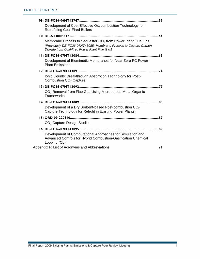
TABLE OF CONTENTS
Final Report 2009 Existing Plants, Emissions & Capture Peer Review Meeting ii
09: DE-FC26-06NT42747 ...................................................................................... 57 Development of Cost Effective Oxycombustion Technology for Retrofitting Coal-Fired Boilers
10: DE-NT0005312 ................................................................................................ 64 Membrane Process to Sequester CO2 from Power Plant Flue Gas (Previously DE-FC26-07NT43085: Membrane Process to Capture Carbon Dioxide from Coal-fired Power Plant Flue Gas)
11: DE-FC26-07NT43084 ...................................................................................... 69 Development of Biomimetic Membranes for Near Zero PC Power Plant Emissions
12: DE-FC26-07NT43091 ...................................................................................... 74 Ionic Liquids: Breakthrough Absorption Technology for Post-Combustion CO2 Capture
13: DE-FC26-07NT43092 ...................................................................................... 77 CO2 Removal from Flue Gas Using Microporous Metal Organic Frameworks
14: DE-FC26-07NT43089 ...................................................................................... 80 Development of a Dry Sorbent-based Post-combustion CO2 Capture Technology for Retrofit in Existing Power Plants
15: ORD-09-220610 ................................................................................................ 87 CO2 Capture Design Studies
16: DE-FC26-07NT43095 ...................................................................................... 89 Development of Computational Approaches for Simulation and Advanced Controls for Hybrid Combustion-Gasification Chemical Looping (CL)
Appendix F: List of Acronyms and Abbreviations 91
Executive Summary
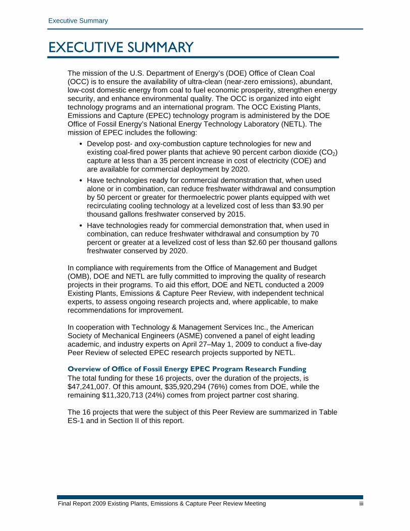
EXECUTIVE SUMMARY The mission of the U.S. Department of Energy’s (DOE) Office of Clean Coal (OCC) is to ensure the availability of ultra-clean (near-zero emissions), abundant, low-cost domestic energy from coal to fuel economic prosperity, strengthen energy security, and enhance environmental quality. The OCC is organized into eight technology programs and an international program. The OCC Existing Plants, Emissions and Capture (EPEC) technology program is administered by the DOE Office of Fossil Energy’s National Energy Technology Laboratory (NETL). The mission of EPEC includes the following:
• Develop post- and oxy-combustion capture technologies for new and existing coal-fired power plants that achieve 90 percent carbon dioxide (CO2) capture at less than a 35 percent increase in cost of electricity (COE) and are available for commercial deployment by 2020.
• Have technologies ready for commercial demonstration that, when used alone or in combination, can reduce freshwater withdrawal and consumption by 50 percent or greater for thermoelectric power plants equipped with wet recirculating cooling technology at a levelized cost of less than $3.90 per thousand gallons freshwater conserved by 2015.
• Have technologies ready for commercial demonstration that, when used in combination, can reduce freshwater withdrawal and consumption by 70 percent or greater at a levelized cost of less than $2.60 per thousand gallons freshwater conserved by 2020.
In compliance with requirements from the Office of Management and Budget (OMB), DOE and NETL are fully committed to improving the quality of research projects in their programs. To aid this effort, DOE and NETL conducted a 2009 Existing Plants, Emissions & Capture Peer Review, with independent technical experts, to assess ongoing research projects and, where applicable, to make recommendations for improvement. In cooperation with Technology & Management Services Inc., the American Society of Mechanical Engineers (ASME) convened a panel of eight leading academic, and industry experts on April 27–May 1, 2009 to conduct a five-day Peer Review of selected EPEC research projects supported by NETL. Overview of Office of Fossil Energy EPEC Program Research Funding The total funding for these 16 projects, over the duration of the projects, is $47,241,007. Of this amount, $35,920,294 (76%) comes from DOE, while the remaining $11,320,713 (24%) comes from project partner cost sharing. The 16 projects that were the subject of this Peer Review are summarized in Table ES-1 and in Section II of this report.
Final Report 2009 Existing Plants, Emissions & Capture Peer Review Meeting iii
Executive Summary
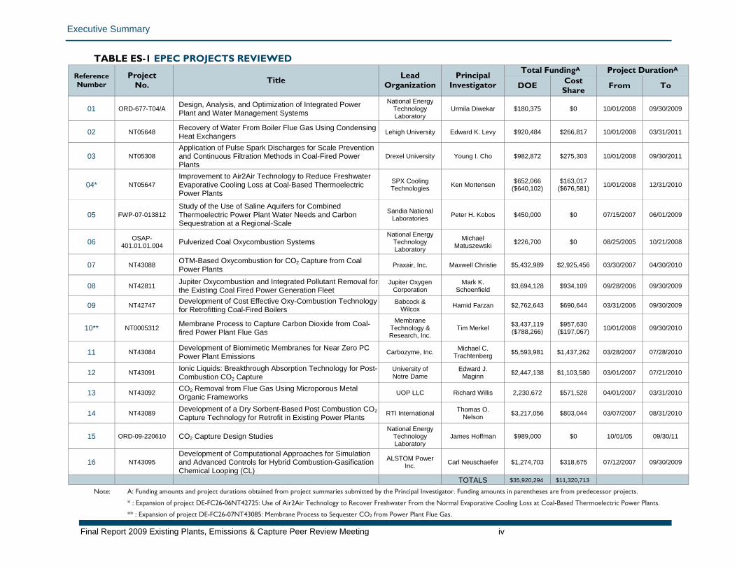
TABLE ES-1 EPEC PROJECTS REVIEWED Reference Number
Project No. Title Lead
Organization Principal
Investigator
Total FundingA Project DurationA
DOE Cost Share From To
01 ORD-677-T04/A Design, Analysis, and Optimization of Integrated Power Plant and Water Management Systems
National Energy Technology Laboratory
Urmila Diwekar $180,375 $0 10/01/2008 09/30/2009
02 NT05648 Recovery of Water From Boiler Flue Gas Using Condensing Heat Exchangers Lehigh University Edward K. Levy $920,484 $266,817 10/01/2008 03/31/2011
03 NT05308 Application of Pulse Spark Discharges for Scale Prevention and Continuous Filtration Methods in Coal-Fired Power Plants
Drexel University Young I. Cho $982,872 $275,303 10/01/2008 09/30/2011
04* NT05647 Improvement to Air2Air Technology to Reduce Freshwater Evaporative Cooling Loss at Coal-Based Thermoelectric Power Plants
SPX Cooling Technologies Ken Mortensen $652,066
($640,102) $163,017
($676,581) 10/01/2008 12/31/2010
05 FWP-07-013812 Study of the Use of Saline Aquifers for Combined Thermoelectric Power Plant Water Needs and Carbon Sequestration at a Regional-Scale
Sandia National Laboratories Peter H. Kobos $450,000 $0 07/15/2007 06/01/2009
06 OSAP-401.01.01.004 Pulverized Coal Oxycombustion Systems
National Energy Technology Laboratory
Michael Matuszewski $226,700 $0 08/25/2005 10/21/2008
07 NT43088 OTM-Based Oxycombustion for CO2 Capture from Coal Power Plants Praxair, Inc. Maxwell Christie $5,432,989 $2,925,456 03/30/2007 04/30/2010
08 NT42811 Jupiter Oxycombustion and Integrated Pollutant Removal for the Existing Coal Fired Power Generation Fleet
Jupiter Oxygen Corporation
Mark K. Schoenfield $3,694,128 $934,109 09/28/2006 09/30/2009
09 NT42747 Development of Cost Effective Oxy-Combustion Technology for Retrofitting Coal-Fired Boilers
Babcock & Wilcox Hamid Farzan $2,762,643 $690,644 03/31/2006 09/30/2009
10** NT0005312 Membrane Process to Capture Carbon Dioxide from Coal-fired Power Plant Flue Gas
Membrane Technology & Research, Inc.
Tim Merkel $3,437,119 ($788,266)
$957,630 ($197,067) 10/01/2008 09/30/2010
11 NT43084 Development of Biomimetic Membranes for Near Zero PC Power Plant Emissions Carbozyme, Inc. Michael C.
Trachtenberg $5,593,981 $1,437,262 03/28/2007 07/28/2010
12 NT43091 Ionic Liquids: Breakthrough Absorption Technology for Post-Combustion CO2 Capture
University of Notre Dame
Edward J. Maginn $2,447,138 $1,103,580 03/01/2007 07/21/2010
13 NT43092 CO2 Removal from Flue Gas Using Microporous Metal Organic Frameworks UOP LLC Richard Willis 2,230,672 $571,528 04/01/2007 03/31/2010
14 NT43089 Development of a Dry Sorbent-Based Post Combustion CO2Capture Technology for Retrofit in Existing Power Plants RTI International Thomas O.
Nelson $3,217,056 $803,044 03/07/2007 08/31/2010
15 ORD-09-220610 CO2 Capture Design Studies National Energy
Technology Laboratory
James Hoffman $989,000 $0 10/01/05 09/30/11
16 NT43095 Development of Computational Approaches for Simulation and Advanced Controls for Hybrid Combustion-Gasification Chemical Looping (CL)
ALSTOM Power Inc. Carl Neuschaefer $1,274,703 $318,675 07/12/2007 09/30/2009
TOTALS $35,920,294 $11,320,713
Note: A: Funding amounts and project durations obtained from project summaries submitted by the Principal Investigator. Funding amounts in parentheses are from predecessor projects.
* : Expansion of project DE-FC26-06NT42725: Use of Air2Air Technology to Recover Freshwater From the Normal Evaporative Cooling Loss at Coal-Based Thermoelectric Power Plants.
** : Expansion of project DE-FC26-07NT43085: Membrane Process to Sequester CO2 from Power Plant Flue Gas.
Final Report 2009 Existing Plants, Emissions & Capture Peer Review Meeting iv
Executive Summary
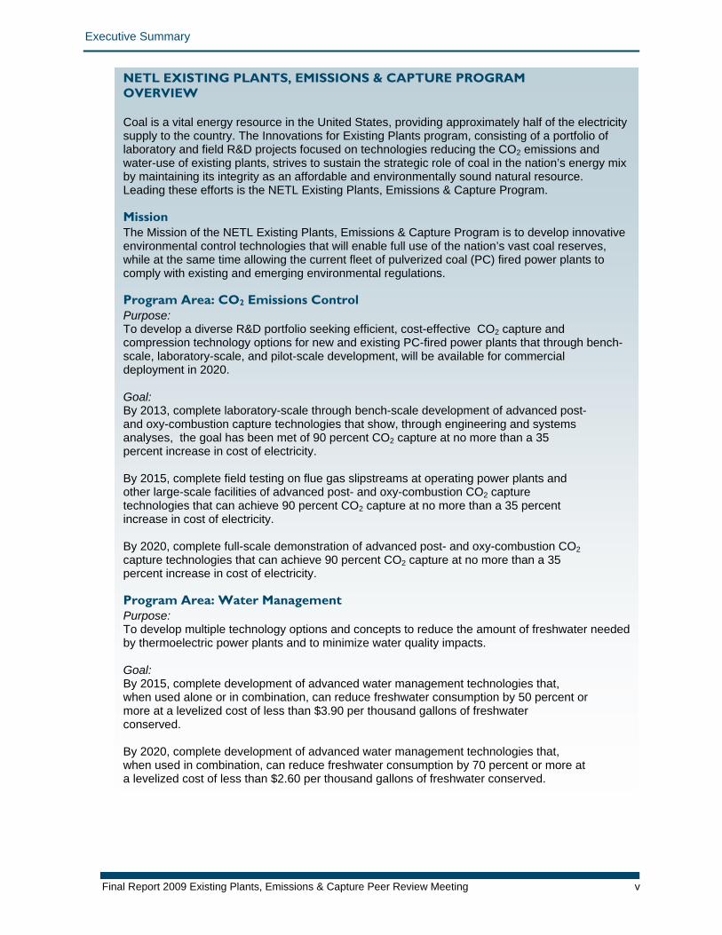
NETL EXISTING PLANTS, EMISSIONS & CAPTURE PROGRAM OVERVIEW Coal is a vital energy resource in the United States, providing approximately half of the electricity supply to the country. The Innovations for Existing Plants program, consisting of a portfolio of laboratory and field R&D projects focused on technologies reducing the CO2 emissions and water-use of existing plants, strives to sustain the strategic role of coal in the nation’s energy mix by maintaining its integrity as an affordable and environmentally sound natural resource. Leading these efforts is the NETL Existing Plants, Emissions & Capture Program. Mission The Mission of the NETL Existing Plants, Emissions & Capture Program is to develop innovative environmental control technologies that will enable full use of the nation’s vast coal reserves, while at the same time allowing the current fleet of pulverized coal (PC) fired power plants to comply with existing and emerging environmental regulations. Program Area: CO2 Emissions Control Purpose: To develop a diverse R&D portfolio seeking efficient, cost-effective CO2 capture and compression technology options for new and existing PC-fired power plants that through bench-scale, laboratory-scale, and pilot-scale development, will be available for commercial deployment in 2020. Goal: By 2013, complete laboratory-scale through bench-scale development of advanced post- and oxy-combustion capture technologies that show, through engineering and systems analyses, the goal has been met of 90 percent CO2 capture at no more than a 35 percent increase in cost of electricity. By 2015, complete field testing on flue gas slipstreams at operating power plants and other large-scale facilities of advanced post- and oxy-combustion CO2 capture technologies that can achieve 90 percent CO2 capture at no more than a 35 percent increase in cost of electricity. By 2020, complete full-scale demonstration of advanced post- and oxy-combustion CO2 capture technologies that can achieve 90 percent CO2 capture at no more than a 35 percent increase in cost of electricity. Program Area: Water Management Purpose: To develop multiple technology options and concepts to reduce the amount of freshwater needed by thermoelectric power plants and to minimize water quality impacts. Goal: By 2015, complete development of advanced water management technologies that, when used alone or in combination, can reduce freshwater consumption by 50 percent or more at a levelized cost of less than $3.90 per thousand gallons of freshwater conserved. By 2020, complete development of advanced water management technologies that, when used in combination, can reduce freshwater consumption by 70 percent or more at a levelized cost of less than $2.60 per thousand gallons of freshwater conserved.
Final Report 2009 Existing Plants, Emissions & Capture Peer Review Meeting v
Executive Summary
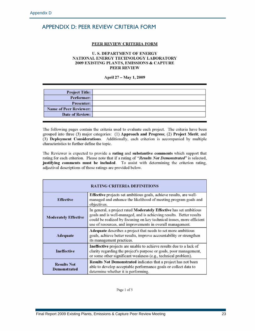
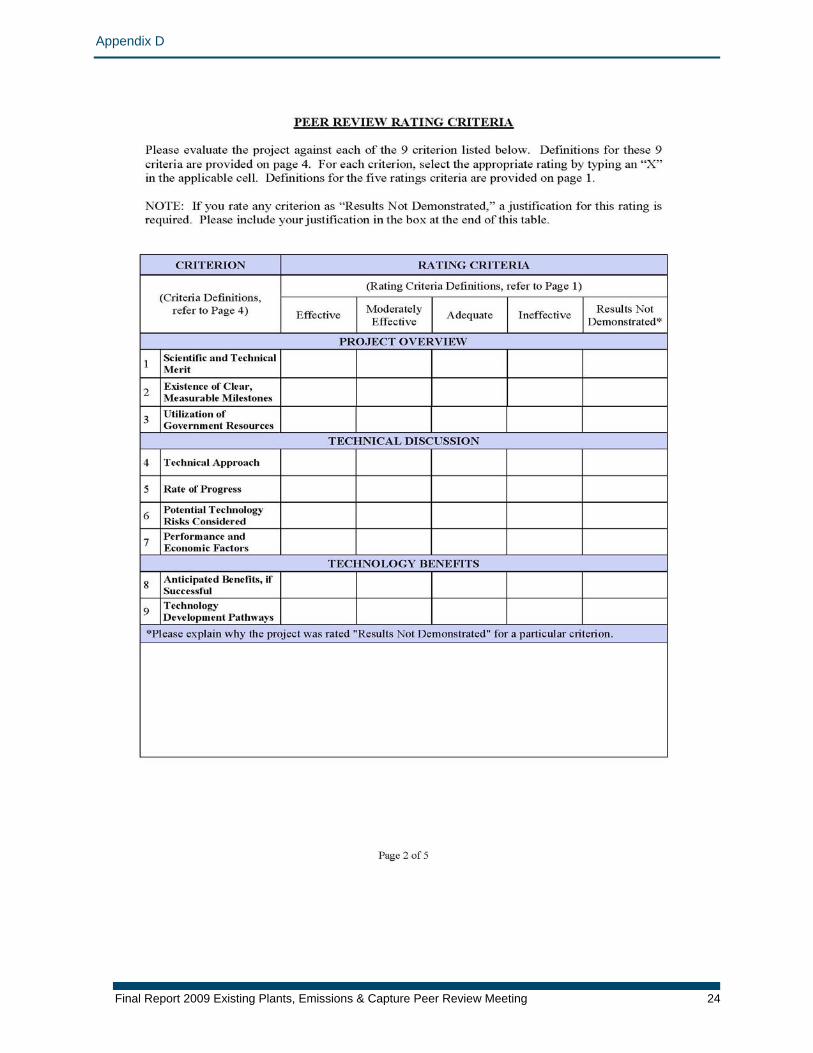
Overview of the Peer Review Process NETL requested that ASME assemble a Peer Review Panel of recognized technical experts to provide recommendations on how to improve the performance, management, and overall results from each individual research project. In advance of the Peer Review Meeting, each project team prepared for the Review Panel an 11-page Project Information Form containing an overview of the project’s purpose, objectives, and achievements, and provided the Review Panel with the presentation to be given at the Peer Review Meeting. At the meeting, each research team made a 45-minute presentation (60 minutes for two of the projects) that was followed by a 30-minute question-and-answer session with the reviewers and a 40-minute closed-session discussion of each project. ASME developed a set of agreed-upon review criteria to be applied to the projects under review by the Review Panel at this meeting. Based on lessons learned from prior Peer Reviews and the special circumstances associated with EPEC research, both the principal investigator (PI) presentations and question-and-answer sessions with the ASME Review Panel were held as closed sessions, limited to the ASME Review Panel and DOE/NETL personnel. The closing of these sessions ensured frank and open discussions between the PIs and members of their team and the Review Panel. Each Panel member then individually evaluated the 16 projects based on a predetermined set of review criteria and provided written comments and recommendations. For each of the nine review criteria, the individual reviewer was asked to score the project as one of the following:
• Effective (5) • Moderately Effective (4) • Adequate (3) • Ineffective (2) • Results Not Demonstrated (1)
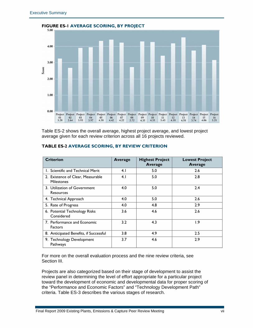
The reviewers occasionally had divergent views of certain projects, particularly when considering criteria “Existence of Clear, Measurable Milestones,” “Performance and Economic Factors,” and “Anticipated Benefits, if Successful.” In the extreme, this divergence is reflected in projects receiving both “1” and “5” ratings in a particular criterion. This result should not be taken as an indication that the panel was indecisive; rather, this reflects the varied backgrounds and differing perspectives which are a sign of a diverse peer review. Such diversity is a strength that allows the Review Panel to review fundamental research, systems studies, and demonstration projects with comparable levels of expertise as a panel. The Review Panel did, however, have differing views regarding the interpretation of specific criteria, particularly those of an economic nature. Figure ES-1 shows the overall average score, including all nine review criteria, for all 16 projects.
Final Report 2009 Existing Plants, Emissions & Capture Peer Review Meeting vi
Executive Summary
FIGURE ES-1 AVERAGE SCORING, BY PROJECT
Table ES-2 shows the overall average, highest project average, and lowest project average given for each review criterion across all 16 projects reviewed. TABLE ES-2 AVERAGE SCORING, BY REVIEW CRITERION
Criterion Average Highest Project Average
Lowest Project Average
1. Scientific and Technical Merit 4.1 5.0 2.6 2. Existence of Clear, Measurable
Milestones 4.1 5.0 2.8
3. Utilization of Government Resources
4.0 5.0 2.4
4. Technical Approach 4.0 5.0 2.6 5. Rate of Progress 4.0 4.8 2.9 6. Potential Technology Risks
Considered 3.6 4.6 2.6
7. Performance and Economic Factors
3.2 4.3 1.9
8. Anticipated Benefits, if Successful 3.8 4.9 2.5 9. Technology Development
Pathways 3.7 4.6 2.9
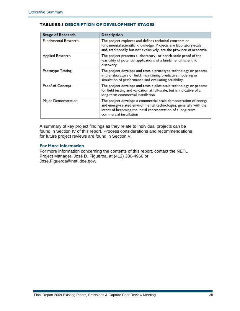
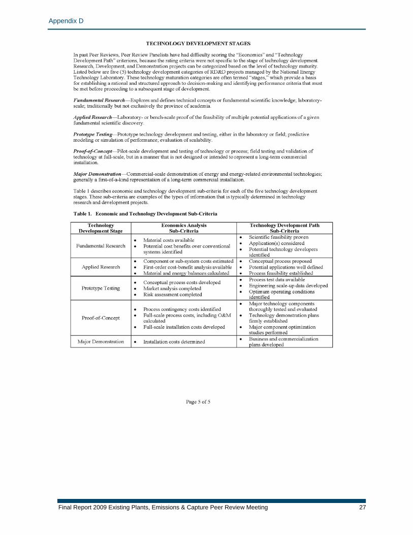
For more on the overall evaluation process and the nine review criteria, see Section III. Projects are also categorized based on their stage of development to assist the review panel in determining the level of effort appropriate for a particular project toward the development of economic and developmental data for proper scoring of the “Performance and Economic Factors” and “Technology Development Path” criteria. Table ES-3 describes the various stages of research.
Final Report 2009 Existing Plants, Emissions & Capture Peer Review Meeting vii
Executive Summary
Final Report 2009 Existing Plants, Emissions & Capture Peer Review Meeting viii
TABLE ES-3 DESCRIPTION OF DEVELOPMENT STAGES
Stage of Research Description Fundamental Research The project explores and defines technical concepts or
fundamental scientific knowledge. Projects are laboratory-scale and, traditionally but not exclusively, are the province of academia.
Applied Research The project presents a laboratory- or bench-scale proof of the feasibility of potential applications of a fundamental scientific discovery.
Prototype Testing The project develops and tests a prototype technology or process in the laboratory or field, maintaining predictive modeling or simulation of performance and evaluating scalability.
Proof-of-Concept The project develops and tests a pilot-scale technology or process for field testing and validation at full-scale, but is indicative of a long-term commercial installation.
Major Demonstration The project develops a commercial-scale demonstration of energy and energy-related environmental technologies, generally with the intent of becoming the initial representation of a long-term commercial installation
A summary of key project findings as they relate to individual projects can be found in Section IV of this report. Process considerations and recommendations for future project reviews are found in Section V. For More Information For more information concerning the contents of this report, contact the NETL Project Manager, José D. Figueroa, at (412) 386-4966 or [email protected].
Introduction
Final Report 2009 Existing Plants, Emissions & Capture Peer Review Meeting 1
I. INTRODUCTION In 2009, the American Society of Mechanical Engineers (ASME) was invited to provide an independent, unbiased, and timely peer review of selected projects within the U.S. Department of Energy (DOE) Office of Fossil Energy Existing Plants, Emissions & Capture (EPEC) program (administered by the Office of Fossil Energy’s National Energy Technology Laboratory [NETL]). On April 27–May 1, 2009 ASME convened a panel of eight leading academic and industry experts to conduct a five-day peer review of selected EPEC research projects supported by NETL. This report contains a summary of the findings from that review. Compliance with OMB Requirements DOE, the Office of Fossil Energy, and NETL are fully committed to improving the quality and results of their projects. The peer review of selected projects within the EPEC program was designed to comply with requirements from the Office of Management and Budget (OMB). Overview of the Peer Review Process ASME was selected as the independent organization to conduct a five-day Peer Review of 16 EPEC projects. ASME performed this project review work as a subcontractor to Technology & Management Services, Inc. (TMS), a NETL prime contractor. NETL selected the 16 projects, while ASME organized an independent Review Panel of eight leading academic, and industry power plant technology experts. Prior to the meeting, principal investigators (PIs) submitted an 11-page written summary (Project Information Form) of their project’s purpose, objectives, and progress. At the meeting, each research team made a 45-minute oral presentation that was followed by a 30-minute question-and-answer session with the Review Panel and a 40-minute Review Panel discussion of each project. Based on lessons learned from prior peer reviews and the special circumstances associated with EPEC program research, both the PI presentations and question-and-answer sessions with the Review Panel for the ASME DOE EPEC Peer Review were held as closed sessions, limited to the Review Panel and DOE/NETL personnel. The closing of these sessions ensured frank and open discussions between the PIs and the Review Panel. Each Review Panel member then individually evaluated the project presented based on a predetermined set of review criteria and provided written comments and recommendations. This document, prepared by ASME, provides a general overview of findings from the Peer Review and is available to the public.
Introduction
Final Report 2009 Existing Plants, Emissions & Capture Peer Review Meeting 2
ASME Center for Research and Technology Development (CRTD) All requests for peer reviews are organized under ASME’s Center for Research and Technology Development (CRTD). CRTD’s Director of Research, Dr. Michael Tinkleman, with advice from the chair of the ASME Board on Research and Technology Development, selects an executive committee of senior ASME members that is responsible for reviewing and selecting all Review Panel members and ensuring there are no conflicts of interest within the Review Panel or the review process. In consultation with NETL, ASME formulates the review meeting agenda, provides information advising the PIs and their colleagues on how to prepare for the review, facilitates the review session, and prepares a summary of the results. A more extensive discussion of the ASME peer review methodology used for the EPEC Peer Review Meeting is provided in Appendix A. A copy of the meeting agenda is provided in Appendix B, and profiles of the Review Panel members are provided in Appendix C. Peer Review Criteria and Peer Review Criteria Forms ASME developed a set of agreed-upon review criteria to be applied to the projects reviewed at this meeting. The review criteria were provided to the Review Panel and PIs in advance of the Peer Review Meeting, and assessment sheets with the review criteria were pre-loaded (one for each project) onto laptop computers for each Review Panel member. During the meeting, the Review Panel members assessed the strengths and weaknesses of each project before providing both recommendations and action items. A more detailed explanation of this process and a sample Peer Review Criteria Form are provided in Appendix D. The following sections of this report summarize findings from the EPEC Program Peer Review Meeting, organized as follows:
II. Summary of Projects Reviewed in 2009 EPEC Peer Review: A list of the 16 projects reviewed and the selection criteria.
III. An Overview of the Evaluation Scores in 2009: Average scores and a summary of evaluations, including analysis and recommendations.
IV. Summary of Key Project Findings: An overview of key findings from project evaluations.
V. Process Considerations for Future Peer Reviews: Lessons learned in this review that may be applied to future reviews.
Summary of Projects Reviewed in 2009 EPEC Peer Review
Final Report 2009 Existing Plants, Emissions & Capture Peer Review Meeting 3
II. SUMMARY OF PROJECTS REVIEWED IN 2009 EPEC PEER REVIEW NETL selected key projects within the EPEC program as well as related projects being conducted in NETL's Office of Research and Development (ORD) and Office of Systems Analysis and Planning (OSAP) to be reviewed by the independent ASME Review Panel. Selected projects are listed below, with the name of the agency or institution leading the research. A short summary of each of the above projects is presented in Appendix E. PROJECTS REVIEWED
01: ORD-677-T04/A Design, Analysis, and Optimization of Integrated Power Plant and Water Management Systems—National Energy Technology Laboratory
02: DE-NT0005648 Recovery of Water from Boiler Flue Gas Using Condensing Heat Exchangers—Lehigh University, Energy Research Center
03: DE-NT0005308 Application of Pulse Spark Discharges for Scale Prevention and Continuous Filtration Methods in Coal-Fired Power Plants—Drexel University
04: DE-NT0005647 Improvement to Air2Air Technology to Reduce Freshwater Evaporative Cooling Loss at Coal-Based Thermoelectric Power Plants—SPX Cooling Technologies
05: FWP-07-013812 Study of the Use of Saline Aquifers for Combined Thermoelectric Power Plant Water Needs and Carbon Sequestration at a Regional-Scale—Sandia National Laboratories
06: OSAP-401.01.01.004 Pulverized Coal Oxycombustion Systems—National Energy Technology Laboratory
07: DE-FC26-07NT43088 OTM-Based Oxycombustion for CO2 Capture from Coal Power Plants—Praxair, Inc.
08: DE-FC26-06NT42811 Jupiter Oxycombustion and Integrated Pollutant Removal for the Existing Coal Fired Power Generation Fleet—Jupiter Oxygen Corporation
09: DE-FC26-06NT42747 Development of Cost Effective Oxy-Combustion Technology for Retrofitting Coal-Fired Boilers—Babcock & Wilcox Power Generation Group
10: DE-NT0005312 Membrane Process to Capture Carbon Dioxide from Coal-fired Power Plant Flue Gas—Membrane Technology & Research, Inc.
Summary of Projects Reviewed in 2009 EPEC Peer Review
Final Report 2009 Existing Plants, Emissions & Capture Peer Review Meeting 4
11: DE-FC26-07NT43084 Development of Biomimetic Membranes for Near Zero PC Power Plant Emissions—Carbozyme, Inc.
12: DE-FC26-07NT43091 Ionic Liquids: Breakthrough Absorption Technology for Post-Combustion CO2 Capture—University of Notre Dame
13: DE-FC26-07NT43092 CO2 Removal from Flue Gas Using Microporous Metal Organic Frameworks—UOP LLC 14: DE-FC26-07NT43089 Development of a Dry Sorbent-Based Post Combustion CO2 Capture Technology for Retrofit in Existing Power Plants—RTI International
15: ORD-09-220610 CO2 Capture Design Studies—National Energy Technology Laboratory
16: DE-FC26-07NT43095 Development of Computational Approaches for Simulation and Advanced Controls for Hybrid Combustion-Gasification Chemical Looping (CL)—ALSTOM Power Inc.
An Overview of the Evaluation Scores in 2009
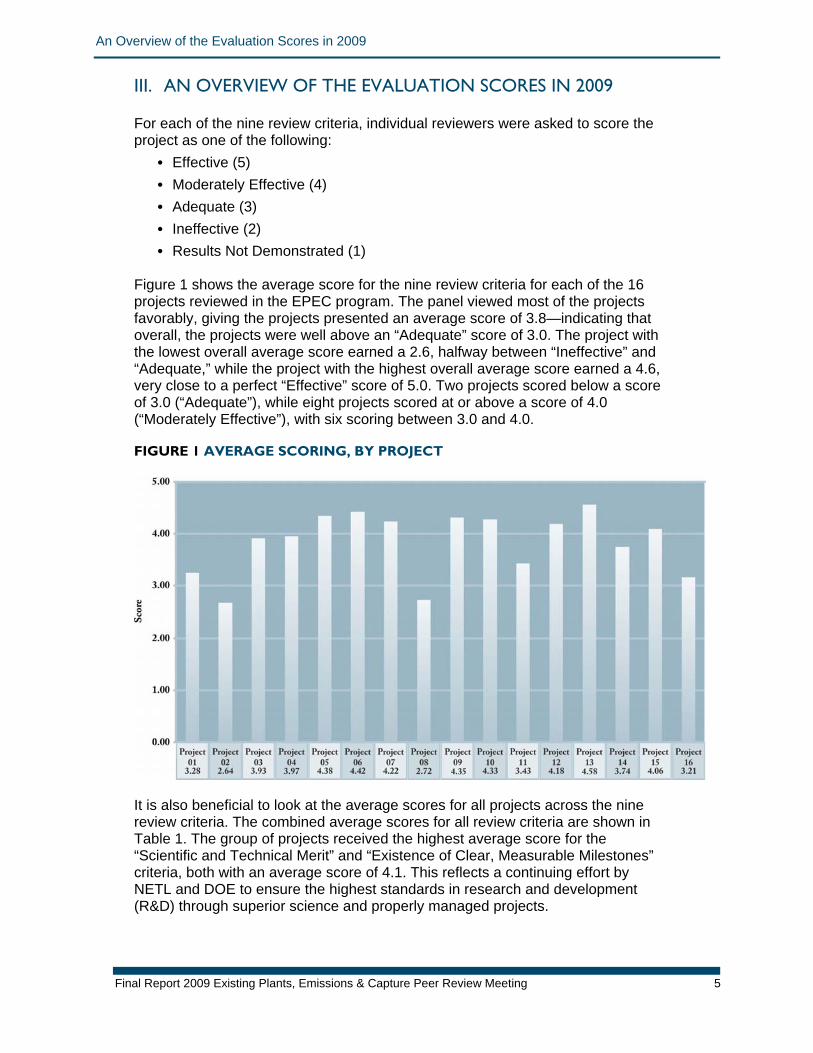
III. AN OVERVIEW OF THE EVALUATION SCORES IN 2009 For each of the nine review criteria, individual reviewers were asked to score the project as one of the following:
• Effective (5) • Moderately Effective (4) • Adequate (3) • Ineffective (2) • Results Not Demonstrated (1)
Figure 1 shows the average score for the nine review criteria for each of the 16 projects reviewed in the EPEC program. The panel viewed most of the projects favorably, giving the projects presented an average score of 3.8—indicating that overall, the projects were well above an “Adequate” score of 3.0. The project with the lowest overall average score earned a 2.6, halfway between “Ineffective” and “Adequate,” while the project with the highest overall average score earned a 4.6, very close to a perfect “Effective” score of 5.0. Two projects scored below a score of 3.0 (“Adequate”), while eight projects scored at or above a score of 4.0 (“Moderately Effective”), with six scoring between 3.0 and 4.0. FIGURE 1 AVERAGE SCORING, BY PROJECT
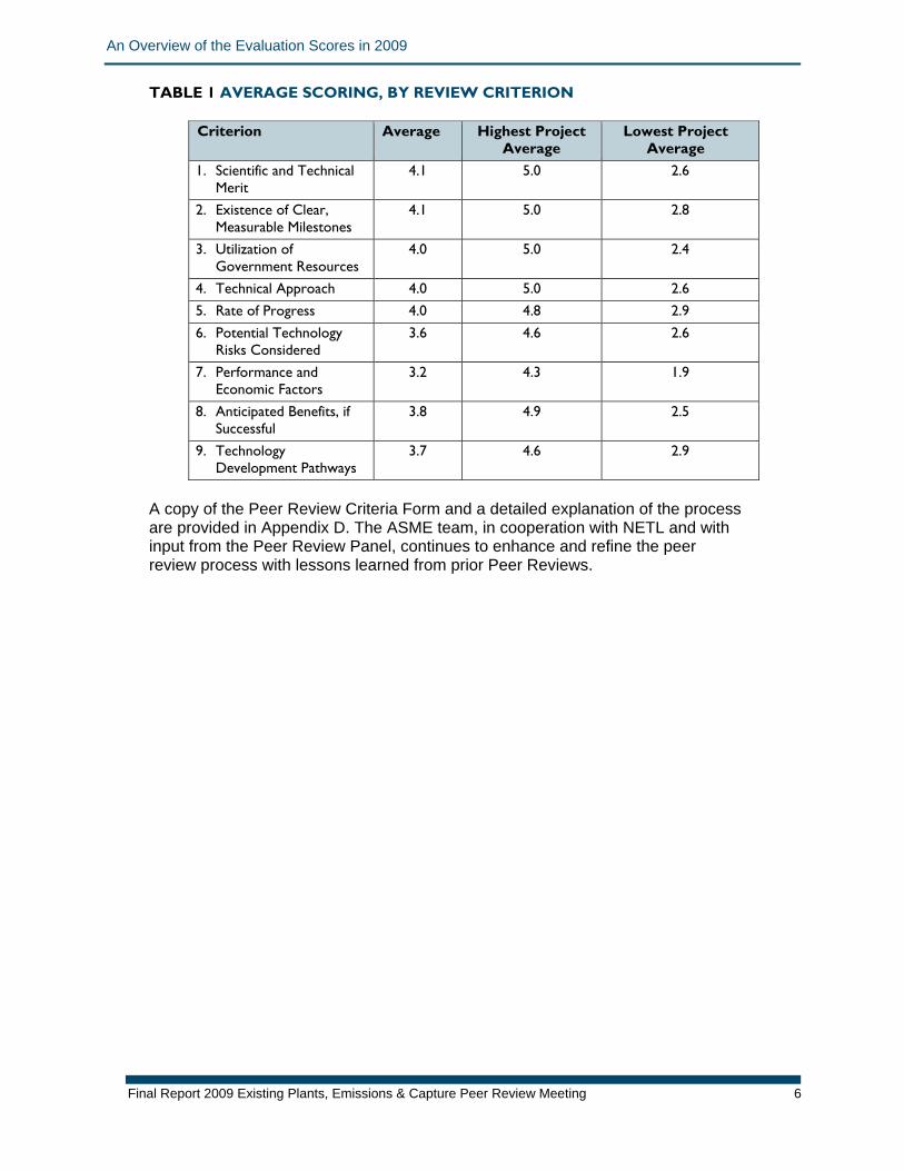
It is also beneficial to look at the average scores for all projects across the nine review criteria. The combined average scores for all review criteria are shown in Table 1. The group of projects received the highest average score for the “Scientific and Technical Merit” and “Existence of Clear, Measurable Milestones” criteria, both with an average score of 4.1. This reflects a continuing effort by NETL and DOE to ensure the highest standards in research and development (R&D) through superior science and properly managed projects.
Final Report 2009 Existing Plants, Emissions & Capture Peer Review Meeting 5
An Overview of the Evaluation Scores in 2009
Final Report 2009 Existing Plants, Emissions & Capture Peer Review Meeting 6
TABLE 1 AVERAGE SCORING, BY REVIEW CRITERION
Criterion Average Highest Project Average
Lowest Project Average
1. Scientific and Technical Merit
4.1 5.0 2.6
2. Existence of Clear, Measurable Milestones
4.1 5.0 2.8
3. Utilization of Government Resources
4.0 5.0 2.4
4. Technical Approach 4.0 5.0 2.6 5. Rate of Progress 4.0 4.8 2.9 6. Potential Technology
Risks Considered 3.6 4.6 2.6
7. Performance and Economic Factors
3.2 4.3 1.9
8. Anticipated Benefits, if Successful
3.8 4.9 2.5
9. Technology Development Pathways
3.7 4.6 2.9
A copy of the Peer Review Criteria Form and a detailed explanation of the process are provided in Appendix D. The ASME team, in cooperation with NETL and with input from the Peer Review Panel, continues to enhance and refine the peer review process with lessons learned from prior Peer Reviews.
Summary of Key Findings
Final Report 2009 Existing Plants, Emissions & Capture Peer Review Meeting 7
IV. SUMMARY OF KEY FINDINGS This section summarizes key findings from across the group of 16 individual projects that were evaluated. General Project Strengths In general, reviewers found the projects to be sound, applauding DOE for presenting a high quality, diverse portfolio. All but two projects had scores that averaged above “Adequate.” As seen in Table I, the Review Panel concluded that many of the projects provided great value for their level of funding and were of high scientific value; the reviewers were impressed by the quality of the projects as well as by their ambitious goals. The Review Panel recognized that many of the projects enjoyed strong partnerships with respected industrial companies, improving the potential for success and the benefits that would be realized. In general, the Review Panel found project leadership and management of the projects impressive and most project teams responsible, experienced in, and passionate about their areas of expertise. Projects run by NETL were noted to be of particularly high caliber.
The eight highest-scoring projects (05, 06, 07, 09, 10, 12, 13, and 15) averaged a 4.0 or better across all criteria. The overall average scores of four criteria in particular were impressive: the average scores for the criteria “Scientific and Technical Merit,” “Existence of Clear, Measurable Milestones,” “Utilization of Government Resources,” and “Technical Approach” were all above 4.0 overall. These scores clearly demonstrate that the responsible use of funding has allowed nearly half of the projects reviewed to effectively achieve their goals. The highest-rated project was Project 13, “CO2 Removal from Flue Gas Using Microporous Metal Organic Framework,” conducted by UOP LLC. This project averaged 4.6 out of 5.0 across all criteria and earned a perfect 5.0 for the criteria “Scientific and Technical Merit,” “Existence of Clear, Measurable Milestones,” and “Technical Approach.” The reviewers were also impressed by the commercial applicability of the products being developed; many of the projects, if successful, would have a significant effect on the carbon storage and/or water management capabilities of power plants. These projects were clearly aware of and working to exceed the success criteria presented by NETL. The reviewers were pleased by the modeling efforts undertaken by many of the teams, which reflect a responsible use of funding and promote effective experimentation. Furthermore, the Review Panel considered of particularly high value those projects that were developing modeling tools for the scientific community, because these projects will promote and enable better science in carbon capture and water management. General Project Weaknesses While many projects performed well in the “Existence of Clear, Measurable Milestones” criterion, the Review Panel noted that some milestones were simply repetitions of the task (i.e., “Perform the experiment”), rather than a performance metric (i.e., “Achieve a result”). The reviewers felt that such milestones allowed projects to prematurely advance. Projects would benefit more from strictly
Summary of Key Findings
Final Report 2009 Existing Plants, Emissions & Capture Peer Review Meeting 8
adhering to clear, performance-based success criteria that must be met before project work can advance. Examples of this problem included several laboratory-scale projects that would benefit from more thorough investigation via modeling, and pilot-scale projects requiring further laboratory-scale testing. The “Performance and Economic Factors” criterion had the lowest average score (3.2) across all projects—a score closer to a rating of “Adequate” than “Moderately Effective.” Though many of the projects appeared to explicitly consider the potential economic impact of the technology being researched, many failed to provide an ultimate estimate of the cost of electricity (COE) at a power plant incorporating their technology. For instance, most projects acknowledged DOE’s goal of a 35% increase in COE at 90% CO2 Capture in introductory slides, but failed to relate how their work could approach or achieve that mandate. The Panel understands that it is more difficult for Fundamental Research Projects to make this assessment than a more mature project, but all projects are required to make some assessment of achieving this goal, even at an extremely basic level. Furthermore, many projects failed to justify their assumptions or provide reliable economic data. There were also two projects that failed to provide sufficient cost and performance data for “Performance and Economic Factors,” earning a score lower than 2.0. Overall, the reviewers thought that there was considerable opportunity for improvement in this area, and hope that, in the future, all projects in this area will be required to explicitly relate their results to the COE. The “Potential Technology Risks Considered” criterion had the next-lowest average score (3.6) across all projects—a score between “Adequate” and Moderately Effective.” The Review Panel found that many of the projects did not adequately identify and plan for the mitigation of factors that could lead to the failure of the technology to be developed and commercialized. The reviewers rated three of the projects below 3.0, indicating that, for these projects to be acceptable, the project teams must examine and plan for potential risks. Issues for Future Consideration On the whole, the reviewers were impressed by the technical expertise, knowledge, and ambition of the researchers. However, the Review Panel found that many projects should have conducted early modeling to complement experiments conducted. Such projects seemed to be moving too quickly, failing to consider the full economic and technical implications of the chosen approach. The reviewers viewed the lacking or limited early economic analysis and early consideration of commercial implementation as two areas offering the greatest opportunities for improvement. As mentioned above, the Review Panel recognized that the “Performance and Economic Factors” criterion was not particularly well understood by project presenters, who often struggled to explicitly relate the project to the ultimate cost of electricity—one of the primary criteria provided by NETL. The Review Panel suggested that all projects should have an economic understanding of their project from its earliest stages; however, one reviewer warned that if subcontractors are to be used to provide economic projections, teams must be extremely clear regarding the desire for accuracy, not precision, to gain reliable data for the minimum cost. Furthermore, a single definition of “commercialization” should be provided to and understood by all project teams.

Summary of Key Findings
Final Report 2009 Existing Plants, Emissions & Capture Peer Review Meeting 9
The Review Panel also noted that several of the projects appeared to have approaches which had been revised mid-course when an initial R&D path proved untenable or likely unsuccessful. The reviewers acknowledged that unsuccessful R&D is to be expected and is not indicative of a weakness in the program; however, restructuring a failed project to continue the work without additional review and improvement will not often result in the project successfully achieving its stated goals.
Process Considerations for Future Peer Reviews
Final Report 2009 Existing Plants, Emissions & Capture Peer Review Meeting 10
V. PROCESS CONSIDERATIONS FOR FUTURE PEER REVIEWS Both the Review Panel members and DOE/NETL managers involved in the peer review offered constructive comments on the review process and possible modifications for the future. Comments were provided at the conclusion of the Peer Review Meeting. The following is a brief summary of ideas recommended for use in planning future project review sessions. General Process Comments All involved agreed unanimously that the current Peer Review process is excellent and requires little or no modification. There was high praise both for the facilitation of the meeting and the superb work of the support staff. Panel members found the computerized score tabulation method effective and beneficial, as it allowed for quick display of a project’s preliminary average score. EPEC Program and Projects Reviewed The presentation and question-and-answer periods were held in closed sessions consisting only of DOE/NETL and ASME personnel and support contractors; the Review Panel; and the project team, allowing for candid discussion of the material. However, several Review Panel members thought that the PIs could have presented more details on certain aspects of these projects without disclosing proprietary information. For a small number of projects, the Review Panel found that the PI did not effectively present the content of the project, and in some cases was unable to effectively answer the Review Panel’s questions. The Review Panel suggested that a shared project presentation including the other partners, particularly industrial partners, would help address this issue. Reviewers asserted that many of the more developed projects would have greatly benefited from an earlier, expert review designed to assess and augment project goals and activities. Meeting Agenda The Review Panel agreed that the information in the DOE roadmap presentation at the beginning of the review should be reinforced briefly at the beginning of each PI presentation. Many reviewers stated that at times they lacked context for a project, which prevented them from seeing how the project related to the EPEC program as a whole. As a result, the reviewers found it necessary to direct programmatic questions to NETL staff throughout the week. Future reviews should consider addressing this issue by requiring PIs to preface their presentations with information about how a project fits within the overall EPEC program. The meeting agenda was found to provide adequate time for presentations, questioning, and subsequent discussion, allowing time for the PI to present the project, for the reviewers to question the PI, and for the Review Panel to discuss the project’s strengths and weaknesses without feeling rushed or overburdened. However, several members of the Review Panel suggested that more time could have been given for questions to be asked, as the reviewers occasionally found that projects were not explored in sufficient depth. While the diverse areas of expertise represented by the Review Panel members offered other reviewers needed insight on various topics during discussion and thus provided more accurate and comprehensive ratings and comments, academic
Process Considerations for Future Peer Reviews
Final Report 2009 Existing Plants, Emissions & Capture Peer Review Meeting 11
representation was perceived as disproportionately small compared to prior peer reviews. The Review Panel suggested that, in future reviews, the Panel composition should reflect a broader base of expertise including more academic representation. Presentations and Evaluations The Reviewers found that, while the presentations were suitable for the review taken as a whole, several projects gave more information than could be easily digested within the timeframe of the review, while others failed to present sufficient relevant data for examination and evaluation. In such instances, Reviewers attempted to elicit additional information during the Questions and Answers session; in limited cases, the PI was unable to provide sufficiently detailed or clear responses to such inquiries. As the Review Panel’s ability to provide value and effectiveness is greatly affected by transparency of information presented, the reviewers proposed that an enhanced basic template, with examples, be provided to the PIs to assist them in providing the necessary information. The information presented should be as clear as possible, and presenters should make an effort to minimize acronyms and jargon. To allow for better understanding and appropriate consideration, the Review Panel suggested that projects be required to provide detailed information comparing and contrasting the technology being developed to relevant, available technologies. Furthermore, each project should specify the composition of the CO2 being delivered, including pressure, contaminants, and inert compounds. Finally, projects must quantify and demonstrate the reliability of all statements made during the presentation. The Review Panel also suggested that further orientation to the review process would benefit the PIs, especially if it would allow them to treat the review as a learning experience and an opportunity to gain expert insight into their project, rather than a simple evaluation. The scoring system, while recognized as valuable as a driver for discussion, was also occasionally a source of confusion for several reviewers. Reviewers sometimes felt that the definitions of the scores did not apply properly to a particular project, leading them to treat the scores purely on a numerical basis. In preparation for future reviews, ASME will work with NETL to revisit the evaluation criteria to determine if additional improvements or clarifications can be made in the evaluation criteria description. On a small number of occasions, the Review Panel found that input from the PI was necessary during the closed-sessions discussion period. Asking the PI to remain accessible (i.e., available, but not in the room) during the discussion period is recommended, with the understanding that PI input will only be sought when absolutely necessary and at the discretion of the facilitator. Review Panel The Review Panel thanked DOE for the opportunity to participate in this Peer Review, citing it as an enjoyable and educational experience.
Appendix A
APPENDICES APPENDIX A: ASME PEER REVIEW METHODOLOGY The American Society of Mechanical Engineers (ASME) has been involved in conducting research since 1909 when it started work on steam boiler safety valves. Since then, the Society has expanded its research activities to a broad range of topics of interest to mechanical engineers. ASME draws on the impressive breadth and depth of technical knowledge among its members and, when necessary, experts from other disciplines for participation in ASME-related research programs. In 1985, ASME created the Center for Research and Technology Development (CRTD) to coordinate ASME’s research programs. As a result of the technical expertise of ASME’s membership and its long commitment to supporting research programs, the Society has often been asked to provide independent, unbiased, and timely reviews of technical research by other organizations, including the federal government. After several years of experience in this area, the Society developed a standardized approach to reviewing research projects. This section provides a brief overview of the review procedure established for the U.S. Department of Energy (DOE)/National Energy Technology Laboratory (NETL) 2009 Existing Plants, Emissions & Capture Peer Review. ASME Knowledge and Community Sector One of the five sectors responsible for the activities of ASME’s 127,000 members worldwide, the Knowledge and Community (K&C) Sector is charged with disseminating technical information, providing forums for discussions to advance the mechanical engineering profession, and managing the Society’s research activities. Board on Research and Technology Development ASME members with suitable industrial, academic, or governmental experience in the assessment of priorities for research and development, as well as in the identification of new or unfulfilled needs, are invited to serve on the Board on Research and Technology Development (BRTD) and to function as liaisons between BRTD and the appropriate ASME sectors, boards, and divisions. The BRTD has organized more than a dozen research committees in specific technical areas. Center for Research and Technology Development The mission of the Center for Research and Technology Development (CRTD) is to effectively plan and manage the collaborative research activities of ASME to meet the needs of the mechanical engineering profession as defined by the ASME members. The CRTD is governed by the BRTD, and day-to-day operations of the CRTD are handled by the director of research and his staff. The director of research serves as staff to the Peer Review Executive Committee, handles all logistical support for the review panel, provides facilitation of the actual review meeting, and prepares all summary documentation.
Final Report 2009 Existing Plants, Emissions & Capture Peer Review Meeting 12
Appendix A
EPEC Peer Review Executive Committee For each set of projects to be reviewed, the BRTD convenes a Peer Review Executive Committee to oversee the review process. The Executive Committee is responsible for seeing that all ASME rules and procedures are followed; reviewing and approving the qualifications of those asked to sit on the Review Panel; ensuring that there are no conflicts of interest in the review process; and reviewing all documentation coming out of the project review. There must be at least three members of the Peer Review Executive Committee, and those members must have experience relevant to the program being reviewed. Members of the 2009 EPEC Peer Review Executive Committee were as follows:
• Richard T. Laudenat, Chair. Mr. Laudenat is the Senior Vice-President of the ASME Knowledge and Communities Sector. He was previously a Vice-President of the ASME Energy Conversion Group and was a member of the ASME Energy Committee.
• William Stenzel, of Sargent & Lundy. Mr. Stenzel is a former chair of the ASME Power Division and past member of the ASME Energy Committee.
• William Worek, of the University of Illinois. Dr. Worek is a past Vice-President of the ASME Energy Resources Group and former chair of the ASME Solar Energy Division. He currently serves on the ASME Mechanical Engineering Department Heads Committee.
EPEC Peer Review Panel The EPEC Peer Review Executive Committee accepted résumés for proposed EPEC Peer Review Panel members from CRTD, from a limited call to ASME members with relevant experience in this area, and from the DOE/NETL program staff. From these sources, the ASME Peer Review Executive Committee selected an eight-member Review Panel and agreed that they had the experience necessary to review the broad range of projects under this program and did not present any conflicts of interest. The Review Panel members needed experience in several subject matters, including oxy-fuel combustion; oxygen production; pulverized coal (PC) and integrated gas combined cycle (IGCC) power plants; power plant design; CO2 capture and removal; chemistry; thermodynamics; sulfur removal; cost and economic analysis; commercialization; membranes; power plant water management; computer modeling; systems analysis; and sequestration. Meeting Preparation and Logistics Prior to the meeting, the project team for each project being reviewed was asked to submit an 11-page Project Information Form including project goals, purpose, accomplishments to date, etc. A standard set of specifications for preparing this document was provided by CRTD. These Project Information Forms were collected and provided to the Review Panel prior to the meeting. Also in advance of the review meeting, CRTD gave the project teams a standard presentation format and set of instructions for the oral presentations they were to prepare for the Review Panel. All presentations were created in PowerPoint format, and reviewers were also given hard-copy handouts of these slides. The Project Information Forms and presentations for all projects were provided to the Review Panel well in advance of the meeting to better prepare for the meeting.
Final Report 2009 Existing Plants, Emissions & Capture Peer Review Meeting 13
Appendix A
Final Report 2009 Existing Plants, Emissions & Capture Peer Review Meeting 14
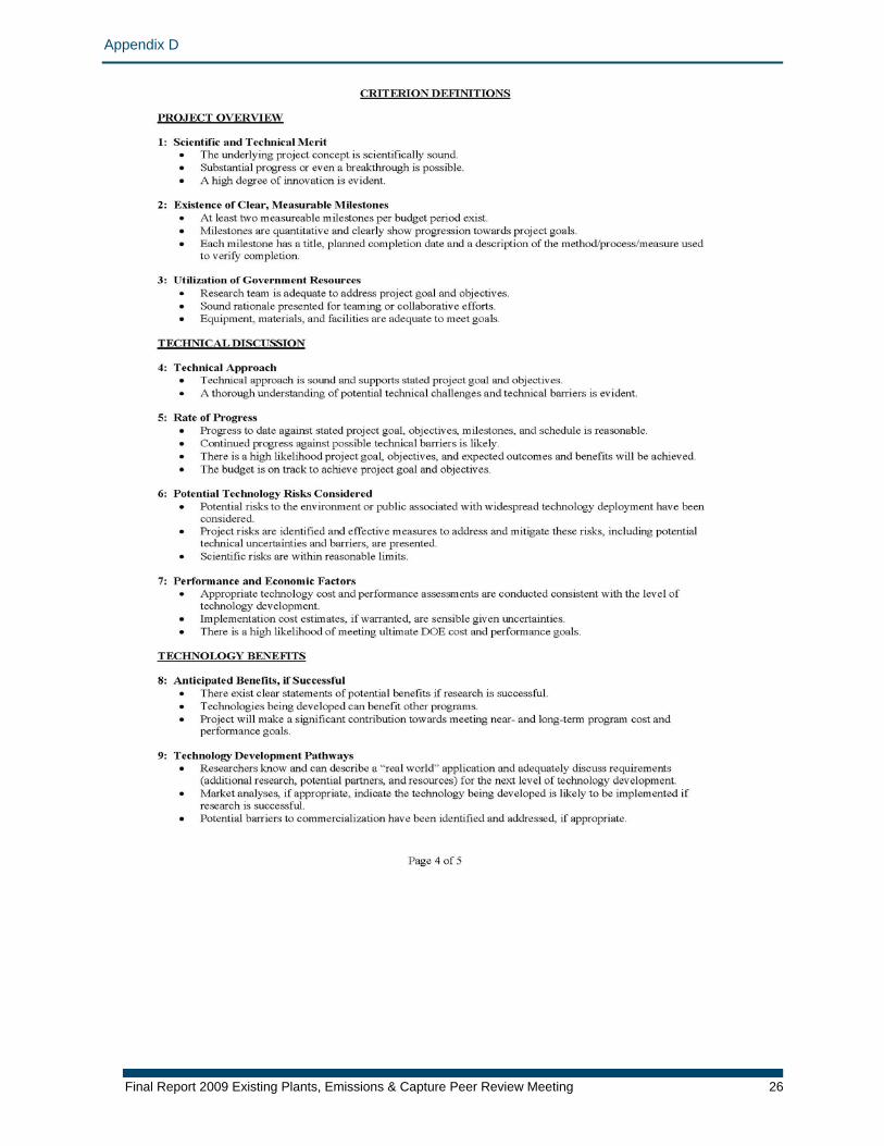
Project Presentations, Evaluations, and Discussion At the EPEC Peer Review Meeting, presenters were held to a time limit of 45 minutes (60 minutes for two of the projects) to allow sufficient time for all presentations within the five-day meeting period. After each presentation, the project team participated in a question-and-answer session with the Review Panel for 30 minutes. The Review Panel then spent 40 minutes evaluating the projects based on the presentation material. To start, each reviewer scored the project against a set of predetermined peer review criteria. The following nine criteria were used:
• Scientific and Technical Merit • Existence of Clear, Measurable Milestones • Utilization of Government Resources • Technical Approach • Rate of Progress • Potential Technology Risks Considered • Performance and Economic Factors • Anticipated Benefits if Successful • Technology Development Pathways
For each of these Review Criteria, individual reviewers scored each project as one of the following:
• Effective (5) • Moderately Effective (4) • Adequate (3) • Ineffective (2) • Results Not Demonstrated (1)
o facilitate the evaluation process, TMS provided reviewers with laptop project.
ct for
Tcomputers that were pre-loaded with Peer Review Criteria Forms for eachAfter scoring the projects on these criteria, the reviewers provided written comments about each project. The Review Panel then discussed the projethe purpose of defining project strengths, project weaknesses, recommendationsfor other possible activities, and a list of action items that the team must address.
Appendix B
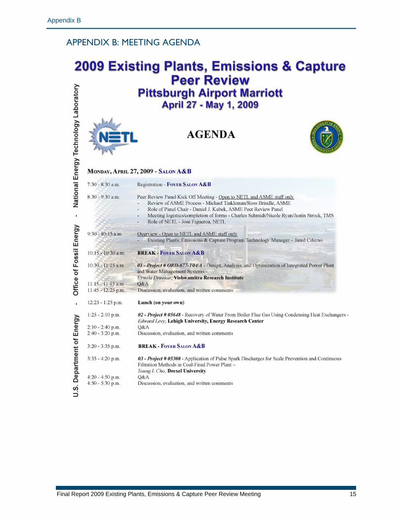
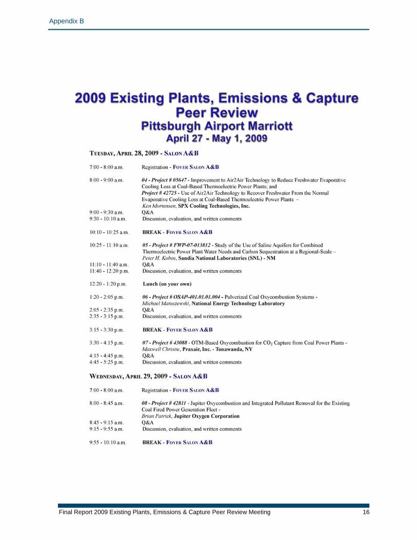
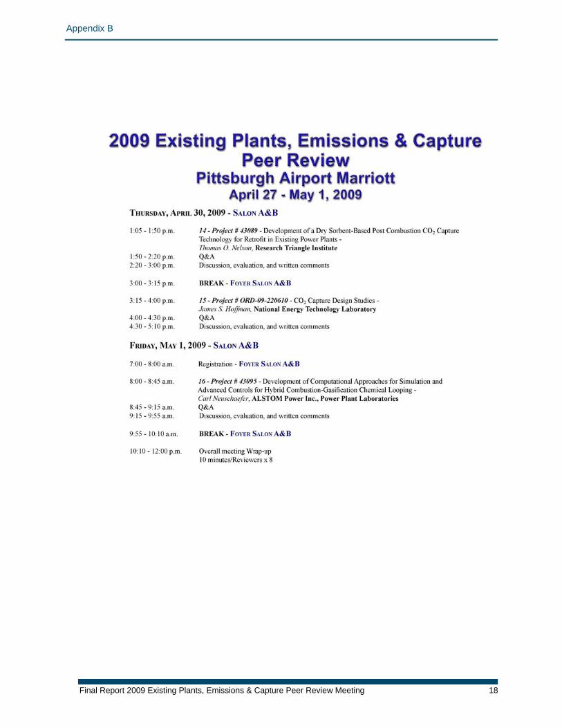
APPENDIX B: MEETING AGENDA
Final Report 2009 Existing Plants, Emissions & Capture Peer Review Meeting 15
Appendix B
Final Report 2009 Existing Plants, Emissions & Capture Peer Review Meeting 16
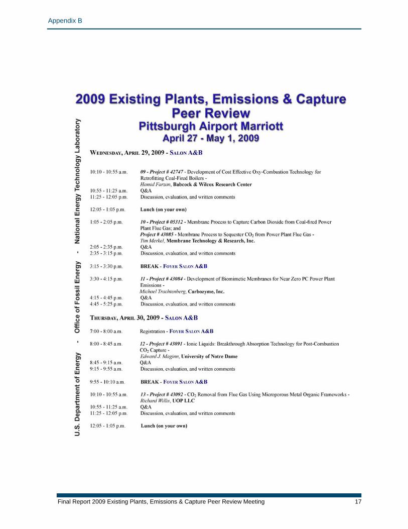
Appendix B
Final Report 2009 Existing Plants, Emissions & Capture Peer Review Meeting 17
Appendix B
Final Report 2009 Existing Plants, Emissions & Capture Peer Review Meeting 18
Appendix C
Final Report 2009 Existing Plants, Emissions & Capture Peer Review Meeting 19
APPENDIX C: PEER REVIEW PANEL MEMBERS After reviewing the scientific areas and issues addressed by the 16 projects to be reviewed, the CRTD staff and the ASME Peer Review Executive Committee, in cooperation with the NETL project manager, identified the following areas of expertise that the 2009 EPEC Peer Review Panel would need to possess:
• Oxy-fuel production and combustion • Pulverized coal (PC) and integrated gasification combined cycle (IGCC)
power plants • Power plant design • CO2 capture and removal • Chemistry and thermodynamics • Sulfur removal • Cost and economic analysis • Commercialization • Membranes • Power plant water management • Computer modeling and systems analysis • Sequestration
It was also important that the Peer Review Panel represent the distinctly different perspectives of academia, industry, government, and nonprofit sectors. Considering the areas of expertise listed above, the CRTD carefully reviewed the résumés of all those who had served on prior ASME Review Panels for DOE (acknowledging the benefit of their previous experience in this form of Peer Review Meeting), a number of new submissions from DOE, and those resulting from a limited call to ASME members with relevant experience. It was determined that six individuals who had served on prior ASME Review Panels were well-qualified to serve on the EPEC Peer Review Panel. Appropriate résumés were then submitted to the EPEC Peer Review Executive Committee for review. The following eight members were selected for the 2009 EPEC Peer Review Panel:
• Daniel J. Kubek, Consultant—Panel Chair
logy Institute
nt
irginia Polytechnic Institute and State
• Stephen Donner, Consultant • Kishore Doshi, Consultant • Dennis Leppin, Gas Techno• Dr. Ravi Prasad, Consultant • James C. Sorensen, Consulta• Martin Van Sickels, Consultant • Dr. Michael R. von Spakovsky, V
University
Appendix C
Panel members reviewed pre-presentation materials and spent five days evaluating projects and providing comments. Panelists received an honorarium for their time as well as reimbursement of travel expenses. A brief summary of their qualifications follows. 2009 EPEC Peer Review Panel Members Daniel J. Kubek – Panel Chair Mr. Kubek is a consultant specializing in synthesis gas and natural gas purification and separation. His clients include the Electric Power Research Institute (EPRI) – CoalFleet, for whom he provides technical guidance on integrated processes for gasification projects; and the Gasification Technologies Council (GTC), where he serves as an advisor on technical issues related to gasification, particularly in the areas of hydrogen sulfide removal and carbon dioxide capture and sequestration. Prior to this, Mr. Kubek was with Universal Oil Products (UOP) for 18 years as senior technology manager. His primary work was for UOP’s solvent absorption, molecular sieve adsorption, and hydrogen processing technologies as applied to natural gas and synthesis gas processing. He was the process manager responsible for all process design packages for multiple gasification projects and served as development manager for their gas-processing business. In 2005, Mr. Kubek was awarded UOP’s Don Carlson Award for Career Technical Innovation. Before joining UOP, he spent 17 years with Union Carbide. Mr. Kubek received a B.S. degree in chemical engineering from Rutgers University and earned an M.S. in chemical engineering from Purdue University. Stephen Donner Mr. Donner is a consultant specializing in power plant chemistry and issues related to the water-steam cycle. Prior to this, Mr. Donner was with Consumers Energy Company for 32 years, during which time he gained extensive experience working in both fossil fuel and nuclear power plants in the water and chemistry area. He was the supervisor of the electric utility central office group with a staff of two engineers supporting chemistry operations for fossil fuel power plants: boiler water, cooling water, makeup water, fuel chemistry, flue gas conditioning, equipment chemical cleaning, and wastewater treatment. The fossil plant fleet consisted of 17 units with a generating capability of 4,400 megawatts ranging in pressure from 900 pounds per square inch (psi) to 3,600 psi. He provided technical support to minimize plant operating and maintenance costs, reduce emissions, and improve plant operating reliability through improvement of system chemistry, and was involved in the design review and environmental permitting processes for selective catalytic reduction and desulfurization flue gas units. He has also worked as a consultant on system chemistry issues outside of the United States, including in Argentina, Australia, Ghana, Morocco, Thailand, and the United Arab Emirates. Mr. Donner received a B.S. in chemical engineering and an M.B.A. from Michigan Technological University. Kishore J. Doshi Mr. Doshi recently retired from HyRadix, Inc where he served as vice president of technology for seven years. At HyRadix, he led the effort to extend the technology to development and commercialization of a small-scale packaged hydrogen plant for industrial applications. Prior to that, he spent 14 years at UOP, where he acquired, integrated, and developed Separex CO2 removal membrane technology with UOP’s polymeric hydrogen membrane technology. The key contribution involved design and development of natural gas pre-purification technology to
Final Report 2009 Existing Plants, Emissions & Capture Peer Review Meeting 20
Appendix C
protect and extend the life of the membrane. Mr. Doshi also spent 20 years at Union Carbide working on CO2 removal projects. His areas of expertise include separation and purification of gas streams, pressure-swing adsorption, membranes, auto-thermal reforming, hydrogen plants, CO2 removal and oxygen/nitrogen air separation. He is an inventor or co-inventor on 18 U.S. patents. Mr. Doshi has a B.S.ChE. from the University of Madras in India and an M.S.ChE. from the University of Cincinnati. Dennis Leppin Mr. Leppin is the director of the Gas Processing Research Group at the Gas Technology Institute (GTI). He manages a substantial research program addressing the removal of sulfur, carbon dioxide and other unwanted constituents from natural gas and synthesis gas, focusing on the development of new process technology. He is experienced in direct injection scavenging, having led a Joint Industry Project in direct injection scavenging research and designed commercial direct injection scavenging installations. Mr. Leppin has been engaged in numerous techno-economic studies connected with GTI process development research, and has previously served as a peer reviewer for DOE/NETL, including a peer review on carbon dioxide capture. He has published more than 150 technical and program-reviewed articles and is a recognized authority on small-scale sulfur removal. Ravi Prasad, Ph.D. Dr. Prasad of Helios-NRG, LLC and formerly a corporate fellow of Praxair Inc., has 60 U.S. patents and broad industrial experience in developing and commercializing new technologies, launching technology programs ($2–$50 million), supporting business development, building cross-functional teams, and setting up joint development alliances. He is a founding member of an alliance involving Praxair, British Petroleum, Amoco, Phillips Petroleum, Statoil, and Sasol to develop ceramic membrane syngas technology for gas-to-liquid processes. He established and led programs for ceramic membrane oxygen technology; co-developed proposals to secure major DOE programs worth $35 million in syngas and $20 million in oxygen; identified novel, solid-state oxygen-generation technology; and conceived and implemented a coherent corporate strategy in nanotechnology. He has championed many initiatives in India, including small on-site hydrogen plants, small gasifiers, and aerospace business opportunities; and developed implementation plans resulting in a new R&D center in Shanghai. Dr. Prasad has a B.S. in mechanical engineering from the Indian Institute of Technology in Kanpur, India, and an M.S. and Ph.D. in mechanical engineering and chemical engineering from the State University of New York, Buffalo, New York. James C. Sorensen Mr. Sorensen is a consultant specializing in the conception and development of clean coal and other energy programs with a focus on IGCC, oxy-fuel combustion, gas-to-liquids (GTL), and air separation and hydrogen/syngas technology. Prior to this, he worked for Air Products and Chemicals both as director of new markets and as director of gasification and energy conversion. While in these positions, his achievements included developing and selling a $26 million ultra clean fuels technology development program that was selected by DOE, selling a $30 million single-train separation facility for a 250 megawatt IGCC power plant, proposing and developing a $22.5 million fossil fuel R&D program selected by DOE, and leading Air Products’ effort on a multi-team proposal selected by DOE for a $180
Final Report 2009 Existing Plants, Emissions & Capture Peer Review Meeting 21
Appendix C
Final Report 2009 Existing Plants, Emissions & Capture Peer Review Meeting 22
million Clean Coal Technology award. Mr. Sorensen is the founding chairman of the Gasification Technologies Council. He received a B.S. degree in chemical engineering from the California Institute of Technology and earned an M.S. in chemical engineering from Washington State University. Mr. Sorensen also earned an M.B.A in general management from Harvard Business School. Martin J. Van Sickels Mr. Martin Van Sickels, president of MVS Consulting LLC, has been in the process and engineering construction business for more than 42 years. During a 30-year career with Kellogg Brown & Root, Inc. (KBR), he was responsible for all research and development programs, including onshore, offshore, operations and maintenance, and infrastructure. He led the development of a ranking methodology for all R&D activities to fully align them with KBR’s strategic and business plans, was a member of the inquiry review and pricing committees, and was chairman of the technology screening and patent committees. His last position at KBR was vice president and chief technology officer, a member of the executive committee. His duties in this position included worldwide responsibility for the management, marketing, and development of all KBR proprietary and licensed technologies (chemicals, fertilizers, olefins, petroleum refining, and coal gasification) and special execution technologies (liquid-nitrogen gas, gas-to-liquid, gas processing, and offshore technology). He received a B.S. in chemical engineering from the City College of New York and an M.S. in chemical engineering from New York University. Michael R. von Spakovsky, Ph.D. Dr. von Spakovsky is a professor of mechanical engineering and director of the Center for Energy Systems Research at the Virginia Polytechnic Institute and State University. He teaches undergraduate- and graduate-level courses in thermodynamics, kinetic theory, fuel cell systems, and energy system design. His research interests include computational methods for modeling and optimizing complex energy systems; methodological approaches for integrated synthesis, design, operation, control, and diagnosis of such systems; and fuel cell applications for both transportation and distributed power generation. He is associate editor for the ASME International Journal of Fuel Cell Science and Technology and an ASME Fellow. He is also editor-in-chief of the International Journal of Thermodynamics as well as chairman of the Executive Committee of the International Center for Applied Thermodynamics. He received a B.S. in aerospace engineering from Auburn University and an M.S. and a Ph.D. in mechanical engineering from the Georgia Institute of Technology.
Appendix D
APPENDIX D: PEER REVIEW CRITERIA FORM
Final Report 2009 Existing Plants, Emissions & Capture Peer Review Meeting 23
Appendix D
Final Report 2009 Existing Plants, Emissions & Capture Peer Review Meeting 24

Appendix D
Final Report 2009 Existing Plants, Emissions & Capture Peer Review Meeting 25
Appendix D
Final Report 2009 Existing Plants, Emissions & Capture Peer Review Meeting 26
Appendix D
Final Report 2009 Existing Plants, Emissions & Capture Peer Review Meeting 27
Appendix E
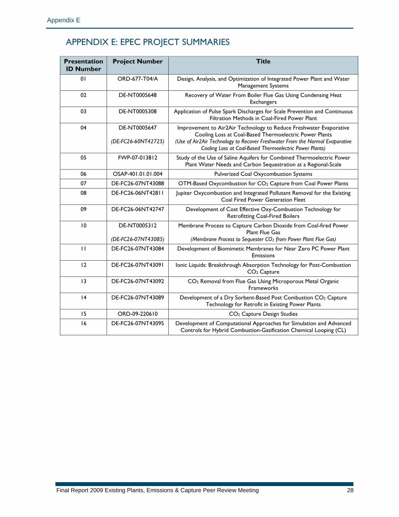
APPENDIX E: EPEC PROJECT SUMMARIES
Presentation ID Number
Project Number Title
01 ORD-677-T04/A Design, Analysis, and Optimization of Integrated Power Plant and Water Management Systems
02 DE-NT0005648 Recovery of Water From Boiler Flue Gas Using Condensing Heat Exchangers
03 DE-NT0005308 Application of Pulse Spark Discharges for Scale Prevention and Continuous Filtration Methods in Coal-Fired Power Plant
04 DE-NT0005647
(DE-FC26-60NT42725)
Improvement to Air2Air Technology to Reduce Freshwater Evaporative Cooling Loss at Coal-Based Thermoelectric Power Plants
(Use of Air2Air Technology to Recover Freshwater From the Normal Evaporative Cooling Loss at Coal-Based Thermoelectric Power Plants)
05 FWP-07-013812 Study of the Use of Saline Aquifers for Combined Thermoelectric Power Plant Water Needs and Carbon Sequestration at a Regional-Scale
06 OSAP-401.01.01.004 Pulverized Coal Oxycombustion Systems
07 DE-FC26-07NT43088 OTM-Based Oxycombustion for CO2 Capture from Coal Power Plants
08 DE-FC26-06NT42811 Jupiter Oxycombustion and Integrated Pollutant Removal for the Existing Coal Fired Power Generation Fleet
09 DE-FC26-06NT42747 Development of Cost Effective Oxy-Combustion Technology for Retrofitting Coal-Fired Boilers
10 DE-NT0005312
(DE-FC26-07NT43085)
Membrane Process to Capture Carbon Dioxide from Coal-fired Power Plant Flue Gas
(Membrane Process to Sequester CO2 from Power Plant Flue Gas)
11 DE-FC26-07NT43084 Development of Biomimetic Membranes for Near Zero PC Power Plant Emissions
12 DE-FC26-07NT43091 Ionic Liquids: Breakthrough Absorption Technology for Post-Combustion CO2 Capture
13 DE-FC26-07NT43092 CO2 Removal from Flue Gas Using Microporous Metal Organic Frameworks
14 DE-FC26-07NT43089 Development of a Dry Sorbent-Based Post Combustion CO2 Capture Technology for Retrofit in Existing Power Plants
15 ORD-09-220610 CO2 Capture Design Studies
16 DE-FC26-07NT43095 Development of Computational Approaches for Simulation and Advanced Controls for Hybrid Combustion-Gasification Chemical Looping (CL)
Final Report 2009 Existing Plants, Emissions & Capture Peer Review Meeting 28
Appendix E
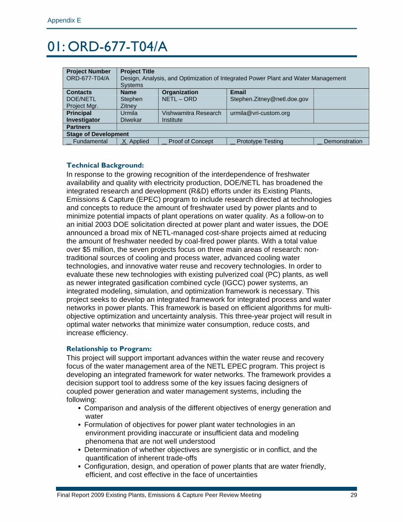
01: ORD-677-T04/A Project Number Project Title ORD-677-T04/A Design, Analysis, and Optimization of Integrated Power Plant and Water Management
Systems Contacts Name Organization Email DOE/NETL Project Mgr.
Stephen Zitney
NETL – ORD [email protected]
Principal Investigator
Urmila Diwekar
Vishwamitra Research Institute
Partners Stage of Development Fundamental X Applied Proof of Concept Prototype Testing Demonstration Technical Background: In response to the growing recognition of the interdependence of freshwater availability and quality with electricity production, DOE/NETL has broadened the integrated research and development (R&D) efforts under its Existing Plants, Emissions & Capture (EPEC) program to include research directed at technologies and concepts to reduce the amount of freshwater used by power plants and to minimize potential impacts of plant operations on water quality. As a follow-on to an initial 2003 DOE solicitation directed at power plant and water issues, the DOE announced a broad mix of NETL-managed cost-share projects aimed at reducing the amount of freshwater needed by coal-fired power plants. With a total value over $5 million, the seven projects focus on three main areas of research: non-traditional sources of cooling and process water, advanced cooling water technologies, and innovative water reuse and recovery technologies. In order to evaluate these new technologies with existing pulverized coal (PC) plants, as well as newer integrated gasification combined cycle (IGCC) power systems, an integrated modeling, simulation, and optimization framework is necessary. This project seeks to develop an integrated framework for integrated process and water networks in power plants. This framework is based on efficient algorithms for multi-objective optimization and uncertainty analysis. This three-year project will result in optimal water networks that minimize water consumption, reduce costs, and increase efficiency. Relationship to Program: This project will support important advances within the water reuse and recovery focus of the water management area of the NETL EPEC program. This project is developing an integrated framework for water networks. The framework provides a decision support tool to address some of the key issues facing designers of coupled power generation and water management systems, including the following:
• Comparison and analysis of the different objectives of energy generation and water
• Formulation of objectives for power plant water technologies in an environment providing inaccurate or insufficient data and modeling phenomena that are not well understood
• Determination of whether objectives are synergistic or in conflict, and the quantification of inherent trade-offs
• Configuration, design, and operation of power plants that are water friendly, efficient, and cost effective in the face of uncertainties
Final Report 2009 Existing Plants, Emissions & Capture Peer Review Meeting 29
Appendix E
• Determination of the sensitivity of water loss to changes in process design • Determination of the probability or risk that an advanced water-related
technology will not achieve expected performance and cost targets • Determination of necessary increases in cost to make power plants flexible
for future water usage considerations • R&D targeting to best reduce critical uncertainties regarding water use
Primary Project Goal: The primary objective of the project is to develop a power plant water management tool built around the Aspen Plus steady-state process simulator. Aspen Plus is the computational workhorse for system studies at NETL and offers solids-handling capabilities important for coal combustion and gasification modeling; comprehensive physical properties, thermodynamics, phase and chemical equilibrium relations, and reaction kinetics for gas cleanup modeling; and an extensive library of heat exchange and rotating equipment models for simulating combined cycles. By developing a water management capability around Aspen Plus, NETL and its contractors will be able to perform systematic evaluations of various integrated power plant and water network concepts. In this project, the power plant water management tool for Aspen Plus will be used to develop baseline case power plant and water network simulations for a conventional PC plant and an IGCC plant. Objectives: The objectives of the project include the following subtasks:
1. Develop a superstructure-based integrated framework for water networks 2. Develop and integrate models for new and existing water management
technologies 3. Develop CAPE-OPEN compliant capabilities for optimization under uncertainties
for single and multiple objectives 4. Find optimal process configurations and designs that are efficient, cost effective,
and that minimize water consumption 5. Develop baseline case power plant and water network simulations for a
conventional PC plant and an IGCC plant
Final Report 2009 Existing Plants, Emissions & Capture Peer Review Meeting 30
Appendix E
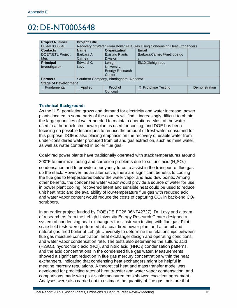
02: DE-NT0005648
Project Number Project TitleDE-NT0005648 Recovery of Water From Boiler Flue Gas Using Condensing Heat Exchangers Contacts Name Organization Email DOE/NETL Project Mgr.
Barbara A. Carney
Existing Plants Division
Principal Investigator
Edward K. Levy
Lehigh University, Energy Research Center
Partners Southern Company, Birmingham, Alabama Stage of Development Fundamental Applied Proof of
Concept X Prototype Testing Demonstration
Technical Background: As the U.S. population grows and demand for electricity and water increase, power plants located in some parts of the country will find it increasingly difficult to obtain the large quantities of water needed to maintain operations. Most of the water used in a thermoelectric power plant is used for cooling, and DOE has been focusing on possible techniques to reduce the amount of freshwater consumed for this purpose. DOE is also placing emphasis on the recovery of usable water from under-considered water produced from oil and gas extraction, such as mine water, as well as water contained in boiler flue gas. Coal-fired power plants have traditionally operated with stack temperatures around 300°F to minimize fouling and corrosion problems due to sulfuric acid (H2SO4) condensation and to provide a buoyancy force to assist in the transport of flue gas up the stack. However, as an alternative, there are significant benefits to cooling the flue gas to temperatures below the water vapor and acid dew points. Among other benefits, the condensed water vapor would provide a source of water for use in power plant cooling; recovered latent and sensible heat could be used to reduce unit heat rate; and the availability of low-temperature flue gas with reduced acid and water vapor content would reduce the costs of capturing CO2 in back-end CO2 scrubbers. In an earlier project funded by DOE (DE-FC26-06NT42727), Dr. Levy and a team of researchers from the Lehigh University Energy Research Center designed a system of condensing heat exchangers for slipstream testing with flue gas. Pilot-scale field tests were performed at a coal-fired power plant and at an oil and natural gas-fired boiler at Lehigh University to determine the relationships between flue gas moisture concentration, heat exchanger design and operating conditions, and water vapor condensation rate. The tests also determined the sulfuric acid (H2SO4), hydrochloric acid (HCl), and nitric acid (HNO3) condensation patterns, and the acid concentrations in the condensed flue gas water. Measurements showed a significant reduction in flue gas mercury concentration within the heat exchangers, indicating that condensing heat exchangers might be helpful in meeting mercury regulations. A theoretical heat and mass transfer model was developed for predicting rates of heat transfer and water vapor condensation, and comparisons made with pilot-scale measurements showed excellent agreement. Analyses were also carried out to estimate the quantity of flue gas moisture that
Final Report 2009 Existing Plants, Emissions & Capture Peer Review Meeting 31
Appendix E
may be practically recovered from boiler flue gas and the magnitude of the heat rate improvements which could be made by recovering sensible and latent heat from flue gas. As a result of the tests and analyses, it was found that from 50%–88% percent of flue gas moisture could be condensed, depending on ambient temperature conditions; for high moisture coals, this represents from 15%–25% of the cooling tower makeup water. Analyses of unit heat rate improvements from utilizing captured sensible and latent heat in the boiler and turbine cycle show potential improvements ranging from 1.8%–3.9%. Relationship to Program: This project will support important advances within the water reuse and recovery focus of the water management area of the NETL Existing Plants, Emissions & Capture program. The primary benefit of the project is the ability to recover flue gas moisture for use as evaporative cooling tower makeup water. Secondary benefits include the capability to improve the unit heat rate; reduce emissions of H2SO4, HCl, and HNO3; and reduce mercury emissions. The technology developed in the project will also be useful as components in carbon capture systems.
Primary Project Goal: The primary goal of the project is to develop cost-effective, corrosion-resistant, condensing heat exchanger systems for use in coal-fired power plants. Objectives: The project is divided into the following subtasks, each with its own objective:
1. Expand the database on condensing heat exchanger water and acid condensation characteristics in coal-fired units by performing slipstream tests at a power plant with bituminous coal and wet flue gas desulfurization scrubbers, as well as at a power plant firing high-moisture semi-bituminous coal
2. Develop cost-effective solutions to reducing acid corrosion of heat exchanger tubes to acceptable levels by developing improved means of restricting most of the sulfuric acid deposition to the high-temperature region of the heat exchanger system; determining concentrations of HCl, HNO3, and H2SO4 in the condensed flue gas moisture; and determining corrosion rates of candidate heat exchanger materials for different regions of the heat exchanger system as functions of acid concentration and temperature
3. Measure mercury capture efficiency as a function of process conditions in power plant field tests
4. Determine condensed flue gas moisture treatment needs 5. Design a condensing heat exchanger for full-scale applications and estimate
installed capital costs
Final Report 2009 Existing Plants, Emissions & Capture Peer Review Meeting 32
Appendix E
03: DE-NT0005308 Project Number Project Title DE-NT0005308 Application of Pulse Spark Discharges for Scale Prevention and Continuous
Filtration Methods in Coal-Fired Power Plant Contacts Name Organization Email DOE/NETL Project Mgr.
Barbara Carney
Existing Plants Division
Principal Investigator
Young I. Cho Drexel University [email protected]
Partners Alexander Fridman, Drexel University Andrei Starikovskiy, Drexel University Yurii Mukhin, Drexel University
Stage of Development Fundamental Applied X Proof of Concept Prototype Testing Demonstration Technical Background: Drexel University has a long history of scientific research into innovations for existing plants. For the past 15 years, the university has studied physical water treatment (PWT) using pulsed electric fields, publishing many technical papers on the topic, including five doctoral theses. The feasibility of PWT has been demonstrated, and the mechanism using permanent magnets and solenoid coils has been explained in research funded by American Society of Heating, Refrigerating, and Air Conditioning Engineers (ASHRAE) Technical Committee 3.6 (Water Treatment). In addition, it has been experimentally confirmed that scale deposits could be completely prevented through the use of solenoid coils simultaneously wrapped around a water feed pipe and a conventional filter. More recently, a number of research and development projects using high-voltage plasma discharges have been conducted, and several different methods to produce plasma discharges directly in water, including corona discharge, spark discharge, arc discharge, and gliding arc discharge, have been investigated. Professor Alex Fridman, co-principal investigator of the proposed study, is one of the most well-known theoretical plasma physicists in the world. The discussion that follows is presented to briefly review the scientific and engineering principles of scale formation on the condenser tubes, as well as a proposed method of scale prevention. Scales in condenser tubes at thermoelectric power plants can be calcium carbonate (CaCO3), magnesium sulfate (MgSO4), or silica-based scales. However, due to the inverse solubility and low-equilibrium concentration of calcium ions, CaCO3 makes up most scale deposits on condenser tubes caused by cooling water. Hence, CaCO3 is the prime focus of the proposed study. There are three reactions that control the rate at which dissolved calcium and carbonate ions recombine and crystallize. Reaction 1 relates the dissociation of bicarbonate ions (HCO3
-) into the hydroxyl ions (OH-) and CO2:
HCO3-(aq) OH-(aq) + CO2(g) (Reaction 1)
Final Report 2009 Existing Plants, Emissions & Capture Peer Review Meeting 33
Appendix E
In Reaction 2, hydroxyl ions produced from Reaction 1 further react with existing bicarbonate ions, producing carbonate ions (CO3
2-) and water (H2O):
OH-(aq) + HCO3-(aq) CO3
2-(aq) + H2O(l) (Reaction 2) Reaction 3 is the reaction between calcium ions (Ca2+) and carbonate ions, resulting in the precipitation and crystallization of calcium carbonate:
Ca2+(aq) + CO32-(aq) CaCO3(s) (Reaction 3)
The Gibbs free energy for the three reactions involved in the CaCO3 precipitation process is 43.6 kilojoules per mol (kJ/mol), -20.9 kJ/mol, and -47.7 kJ/mol, respectively. Based on the Gibbs free energy value, Reaction 1 cannot take place spontaneously because it is positive, indicating an endothermic process. For example, when hard water is heated and enough thermal energy is added to water, HCO3
- can be dissociated, producing OH- and subsequently precipitating CaCO3 via Reactions 2 and 3. Note that Reactions 2 and 3 will proceed in the forward direction spontaneously. Therefore, by simply increasing the water temperature, one can easily precipitate calcium ions from circulating cooling water, preventing scale deposits in the condenser tubes. While technically sound and simple, this method would be too costly. The present proposed study attempts to dissociate the bicarbonate ions using direct spark discharges in water. Next, it is necessary to compare the number of OH- from bulk heating and that from the spark discharge in the proposed study. The amount of OH- one can produce per unit time is calculated as:
nOH- = nHCO3- x k
where nHCO3 is the number of HCO3 participating in Reaction 1 and k is the reaction rate coefficient. According to the Arrhenius equation, k = Ae-Ea/T, where Ea is activation energy and T is the system temperature (in electronvolts [eV]). Due to the exponential curve of the equation, the Arrhenius equation indicates that the higher water temperatures will facilitate faster reactions. The proposed study utilizes spark discharges in water; hence, one can expect a very intense local heating of a small volume of water around the electrode, significantly raising the temperature of a small volume of water. The important scientific issue is whether the spark discharge to be used in the proposed study can dissociate HCO3
- without spending a large amount of electrical energy. Below, two cases are presented to identify which produces more OH- for the same energy spent. Case 1. Volume heating: Heat the entire volume by one degree (e.g., from 300 Kelvin [K] to 301 K). The number of OH- produced for Ea≈1 eV becomes:
nOH- = nHCO3- x k =nHCO3- x Ae-Ea/T = AnHCO3- e-11000/301 =e-36.5AnHCO3-
Final Report 2009 Existing Plants, Emissions & Capture Peer Review Meeting 34
Appendix E
Case 2. Local heating: Using spark discharge, assume to heat 1% of the entire water volume 100 degrees (from 300 K to 400 K). The amount of HCO3
- precipitating the reaction is 1% because spark discharge is assumed to heat only 1% of the total water volume. Then, the amount of OH- produced for Ea≈1 eV becomes:
n'OH- = n’HCO3- x k’ =n’HCO3- x Ae-Ea/T = 0.01AnHCO3- e-11000/400 = 0.01e-27.5AnHCO3- = e-32AnHCO3- Comparing the number of the hydroxyl ions produced for the two cases, nOH- and n’OH-, it is evident that local heating by spark discharge can produce about 100 times more OH-, and is therefore 100 times more efficient for precipitating dissolved calcium ions in hard water. In conclusion, the proposed study has the following scale-prevention hypothesis: Spark discharge produces extremely hot local temperature around the tip of the electrode, dissociating bicarbonate ions into hydroxyl ions and carbon dioxide, as shown in Reaction 1, without spending a large amount of energy. Once hydroxyl ions are produced, Reactions 2 and 3 take place spontaneously, resulting in the precipitation of dissolved calcium ions (in water, not on the condenser tubes) and the prevention of scaling on the condenser tubes. The proposed study attempts to continuously remove the suspended calcium particles using a self-cleaning filter such that the concentration of cycle (COC) in the circulating cooling water can be raised to 8–10. Relationship to Program: This project will support important advances within the advanced cooling water focus of the water management area of the NETL EPEC program. The most significant benefit of the proposed work is that spark discharge technology allows a cooling tower to operate at a much higher COC than the current standard of 3–4, while minimizing or preventing scales on the condenser tubes. Of note is that even though the makeup water to the cooling tower is soft water, evaporation of pure water increases the calcium concentration in circulating water to a level that requires blowdown within a week. The high concentration of dissolved calcium ions in recirculating water causes the condenser tube fouling, thus reducing the efficiency of thermoelectric power plants. Hard water causes similar fouling problems associated with calcium deposits in other industries (e.g., petroleum, chemical, food, agricultural, and desalination) and in air-conditioning equipment. Under the current funding cycle, spark discharge technology which allows the filter to remain clean, has successfully been developed. The proposed work attempts to use the same spark discharge technology for scale prevention while doubling COC in cooling water application. Once the work proposed in the next funding cycle is completed, the same spark discharge device may be utilized for both scale prevention and a continuously-cleaning filter system. The proposed technology attempts to precipitate dissolved calcium ions to calcium salt particles. The self-cleaning filter can be used continuously to remove these solid particulates from circulating water. If successful, the calcium concentration can be maintained at a level equivalent to a COC of 3 with a reduced blowdown of 7 gallons. Since evaporative loss remains constant, the COC increases from 3 to
Final Report 2009 Existing Plants, Emissions & Capture Peer Review Meeting 35
Appendix E
7.7 and makeup water can be reduced by 23%. A modern 1,000-megawatt (MW) fossil-fueled power plant with 40% efficiency would reject 1,500 MW of heat at full load; this is roughly equivalent to 512 x 106 British thermal units (Btu)/hr and uses about 760,000 gallons per minute of circulating water based on a 10°C (18°F) temperature difference in the condenser. As heat is removed via evaporation of pure water at a cooling tower, the need for makeup water is about 7,500 gal/min for the typical fossil plant, which results in 10 million gallons per day (GPD). The proposed technology should allow us to operate cooling tower at a COC of 8. Thus, the proposed technology can reduce the blowdown by approximately 25%. This means that the makeup water can be reduced by 2.5 million GPD in a 1,000 MW fossil-fueled power plant. Essentially, the proposed work attempts to develop a mechanical softener with which one can convert hard water to soft water without the use of chemicals and without having to replace expensive filter membranes. The proposed water treatment technology using spark discharges can also replace ion exchange systems often used at homes in hard-water regions. Since ion exchange units release sodium ions into freshwater resources, the proposed work can make a major improvement in protecting water resources by stopping their release. The proposed technology can also prevent or minimize fouling problems in condenser tubes in the desalination process. Primary Project Goal: The primary project goal is to precipitate and remove excess calcium ions in cooling water, preventing condenser-tube fouling and doubling the COC. Achievement of this task will significantly reduce freshwater withdrawal in thermoelectric power plants. Objectives: The objectives of the project are divided into the following tasks, each with its own objectives:
1. Precipitation of dissolved calcium ions using spark discharge (Year 1): One of the primary reasons why thermoelectric generation accounted for 39% (136 billion GPD) of all freshwater withdrawals in the nation in 2000 is that the concentration of mineral ions (such as calcium and magnesium) in the circulating cooling water increases with time as pure water evaporates to remove heat from condenser tubes. In order to maintain a desirable calcium level in the cooling water (i.e., a COC of 3.5), cooling water must continuously be replaced with makeup water. Task 1 attempts to maintain the desired calcium ion concentration in recirculating cooling water by precipitating dissolved calcium ions with spark discharges. The water in a cooling tower is essentially supersaturated hard water, in terms of calcium ions, at a pH of 8–10. Supersaturated hard water is very unstable, and excess calcium ions are ready to precipitate and form calcium salt particles. Problematically, precipitation requires the dissociation of bicarbonate ions, an endothermic process requiring a large amount of energy (i.e., ΔG = +43.6 kJ/mol). Spark discharges produce a strong electric field of 1,000,000 V/cm in water along with strong shock waves, and this research seeks to show that it can precipitate excess calcium ions into calcium particles through the mechanism mentioned in the previous section. In Task 1, the effects of the electrode tip shape, electrode materials (currently stainless steel wire), the distance between two electrodes, the erosion issue of the electrode, etc., on the precipitation of excess calcium
Final Report 2009 Existing Plants, Emissions & Capture Peer Review Meeting 36
Appendix E
ions in cooling water will be examined by modeling and experimental study. Task 1 is divided into the following subtasks: 1.1. Modeling of Ca2+ precipitation process using variables in water side: The
objective of this subtask is to investigate whether different cooling water conditions alter the Ca2+ precipitation efficiency of the spark discharges through computer modeling of the precipitation procedure. Both analytical and experimental approaches will be pursued.
1.2. Parametric study of Ca2+ precipitation process using variables in power supply side: The objective of this subtask is to investigate whether different spark configurations alter Ca2+ precipitation efficiency of the spark discharges.
1.3. Optimization of electrode configuration for most efficient spark discharges: The objective of this subtask is to investigate the effects of electrode materials and geometry on Ca2+ precipitation efficiency.
2. Validation experiments to increase COC (Year 2): For the Task 2 study, a laboratory cooling tower will be built, where pure water continuously evaporates as heat is added through a small heat exchanger. In the laboratory tower, the amount of water lost by evaporation, wind, and blowdown is automatically replaced by a makeup water valve, which is a floating valve located at the tower sump. The cooling tower will have automatic blowdown capability with a solenoid valve that is controlled by a preset conductivity meter. A typical cooling tower operation will be simulated using tap water supplied by the city of Philadelphia. Task 2 is divided into the following subtasks: 2.1. Tests with COC of 4: The objective of this subtask is to investigate
whether the proposed work can increase the COC to 4. 2.2. Tests with COC of 6: The above test will be repeated for the case of
COC of 6. 2.3. Tests with COC of 8: The above test will be repeated for the case of
COC of 8. 2.4. Tests with zero blowdown: The objective of this subtask is to
investigate whether the proposed work can allow the cooling tower operation with zero blowdown. Theoretically, if one can continuously remove precipitated particles suspended in cooling water, there should be no need for blowdown.
3. Validation experiments for scale prevention (Year 3): The objective of Task 3 is to investigate whether the proposed spark discharge technology can prevent or minimize scale deposits on the condenser tubes. A series of heat transfer fouling tests will be conducted using a condenser heat exchanger in the laboratory cooling tower; the fouling resistance will be experimentally determined by measuring the inlet and outlet temperatures at both cooling-water side and hot-fluid side. The fouling resistance obtained with the proposed scale-prevention technology will be compared with the no-treatment case as well as the scale-free case. Task 3 is divided into the following subtasks: 3.1. Tests with COC of 4: This task will determine a baseline in terms of
fouling resistance over time, after which the proposed spark discharge technology will be tested under the identical conditions for the case of COC = 4.
3.2. Tests with COC of 6: The above test will be repeated for the case of COC of 6.
3.3. Tests with COC of 8: The above test will be repeated for the case of COC of 8.
Tests with zero blowdown: Similar to task 2.4, this task seeks to investigate the feasibility of removing blowdown.
Final Report 2009 Existing Plants, Emissions & Capture Peer Review Meeting 37
Appendix E
04: DE-NT0005647 and DE-FC26-06NT42725
Project Number Project Title DE-NT0005647 DE-FC26-06NT42725
Improvement to Air2Air Technology to Reduce Freshwater Evaporative Cooling Loss at Coal-Based Thermoelectric Power Plants Use of Air2Air Technology to Recover Freshwater From the Normal Evaporative Cooling Loss at Coal-Based Thermoelectric Power Plants
Contacts Name Organization Email DOE/NETL Project Mgr.
Barbara A. Carney
Existing Plants Division
Principal Investigator
Ken Mortensen
SPX Cooling Technologies, Inc.
Partners Public Service of New Mexico [DE-FC26-06NT42725 only] Stage of Development Fundamental Applied Proof of
Concept X Prototype Testing Demonstration
Technical Background: The water savings potential of Air2Air™ condensing technology on evaporative cooling processes is substantial. At a 20% annual average water recovery rate, which appears near the mid-point within the possible range of 15%–25% water recovery, the cooling water savings in condensed evaporate for the total United States would be 1.56 billion gallons/day (GPD) if all power and industrial towers were outfitted with this technology. By this standard, the savings would be 188 million GPD in California alone, enough water for 2.6 million residents’ domestic in-home usage (71 GPD/person). This magnitude of water savings would allow relief from drought conditions or additional growth in many water-starved portions of the continental United States. The projected water savings have now been confirmed by the validation testing in DE-FC26-06NT42725. Relationship to Program: This project will support important water conservation advances within the advanced cooling water focus of the water management area of the NETL EPEC program. Thermoelectric generation is water intensive, whether from fossil fuels such as coal, oil, and natural gas, or from nuclear power. In fact, each kilowatt-hour generated requires an average of 25 gallons of water. This means that U.S. citizens may indirectly depend on water to turn on lights and run appliances as much as they may directly use water to take showers and water their lawns. As the nation’s growing economy drives the need for more electricity, demands on the use of water for power generation also will grow. The direct and indirect demand for water for energy production will increasingly compete with demands from other sectors of the economy. As a result, increased attention is being paid to the availability of adequate water supplies required to produce electricity and to the potential impact of energy operations on water quality. The retrofit of Air2Air technology on existing cooling towers and the implementation of the technology in new cooling towers would reduce freshwater consumption of thermoelectric power plants. In the case of saltwater cooling towers, high quality freshwater can be generated for other uses. For example, the cooling tower of a typical 300 megawatt coal-fired power plant recirculates 140,000 gallons per minute of water at a cooling range of 20°F. The water
Final Report 2009 Existing Plants, Emissions & Capture Peer Review Meeting 38
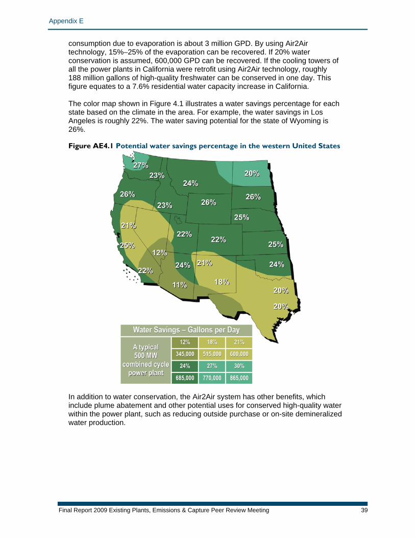
Appendix E
consumption due to evaporation is about 3 million GPD. By using Air2Air technology, 15%–25% of the evaporation can be recovered. If 20% water conservation is assumed, 600,000 GPD can be recovered. If the cooling towers of all the power plants in California were retrofit using Air2Air technology, roughly 188 million gallons of high-quality freshwater can be conserved in one day. This figure equates to a 7.6% residential water capacity increase in California. The color map shown in Figure 4.1 illustrates a water savings percentage for each state based on the climate in the area. For example, the water savings in Los Angeles is roughly 22%. The water saving potential for the state of Wyoming is 26%. Figure AE4.1 Potential water savings percentage in the western United States
In addition to water conservation, the Air2Air system has other benefits, which include plume abatement and other potential uses for conserved high-quality water within the power plant, such as reducing outside purchase or on-site demineralized water production.
Final Report 2009 Existing Plants, Emissions & Capture Peer Review Meeting 39
Appendix E
Primary Project Goal: The objective of the initial project is to determine the benefits of using Air2Air condensing technology in cooling tower applications. The project will add this new technology to an existing evaporative cooling tower at a selected coal power plant. Water recovery from the normal evaporate will be studied and quantified. Performance and operating parameters using Air2Air condensing technology in a cooling tower application will be determined. The project will also analyze the water quality for specific in-plant usage. A freezing condition study of the Air2Air condensing technology will look at module freeze and structural damage to the modules and supports, if any. Finally, the project will develop wet/dry air mixing systems for plume dissipation on the Air2Air hybrid cooling tower system. It will compare this technology’s plume abatement capability to existing systems. The second project’s objective is to further enable Air2Air to become a commercially viable water savings technology by solving issues of economy as they relate to superstructure volume, pack cost, and ducting details. A more efficient heat transfer pack with watertight wet path seals is required to improve the performance and reduce the costs of using Air2Air condensing technology in new and existing evaporative cooling tower applications. Objectives: After successful laboratory-scale testing of the initial project, pilot-scale testing is required to resolve practical issues, such as whether the math model created based on laboratory test data is adequate for the real-size cooling tower. The initial project will be divided into the following subtasks:
1. Retrofit one cooling tower cell using Air2Air technology 2. Monitor the Air2Air condensing pack annually and check the math model for
validation 3. Develop water collection system 4. Conduct water quality analysis and identify applications that are able to use the
collected water 5. Conduct freezing study on Air2Air condensing pack 6. Develop wet/dry air mixing system for plume abatement 7. Study plume dissipation after it is discharged from fan
For the second project, the objective is to analyze the key factors affecting Air2Air Cooling Tower design and configuration, as well as how those parameters relate to Air2Air pack geometry and orientation, which will be determined using computational fluid dynamics techniques. Initial packs will be made using manufacturing techniques most suited to produce the Air2Air geometries and configurations that are best for overall economy of this water conservation system. These test packs will be performance tested, both physically and thermodynamically, to ensure that they have produced the desired improvements. The second project will be divided into the following subtasks:
1. Conduct general Air2Air tower configuration study (general arrangement): Design of the tower, including Air2Air packing, ducting support, and plenum
2. Perform Air2Air heat exchanger enhancement study: Effective surface treatment and sheet spacing
3. Develop Air2Air pack seal: economical and effective method of sealing the wet path tubes. Identify methods: Laboratory production-scale prototypes of processes for one or more of these processes may be implemented
4. Run laboratory thermal testing of new Air2Air pack 5. Report results
Final Report 2009 Existing Plants, Emissions & Capture Peer Review Meeting 40
Appendix E
05: FWP-07-013812 Project Number Project Title FWP-07-013812 Study of the Use of Saline Aquifers for Combined Thermoelectric Power Plant Water
Needs and Carbon Sequestration at a Regional-Scale Contacts Name Organization Email DOE/NETL Project Mgr.
Andrea McNemar
Existing Plants Division
Principal Investigator
Peter H. Kobos
Sandia National Laboratories (SNL), New Mexico
Partners Stage of Development Fundamental Applied Proof of
Concept X Prototype Testing
Demonstration Technical Background: A methodology was developed to test the feasibility of linking coal-fired power plants, deep saline formations for carbon sequestration, and cooling water treatment technologies. A case study examines the San Juan Generating Station with the Morrison Formation in the San Juan Basin in northwest New Mexico. The framework was developed into a dynamic simulation model to examine scenarios regarding varying levels of CO2 sequestration from the power plant, water recovery rates from the formation, and variable costs associated with the components of the whole system. The Phase I work identified the high-level results of a case study that combined CO2 sequestration and brackish water treatment for cooling. Phase II continues to address several key model parameters, such as CO2 injection rates, CO2 fate and transport in the formation, and the system’s economics, that may substantially alter the initial findings. The results presented here indicate that coupling CO2 sequestration and extracted water for treatment and use in a power plant may be feasible. However, the applicability of the coupled system relies on several unique site- and case-specific aspects of the power plant and geologic systems that will greatly affect the physical and economic challenges associated with the overarching system. Relationship to Program: This project will support important advances within the non-traditional sources of process and cooling water focus of the water management area of the NETL EPEC program. The benefits to this program include the development of an analytical framework that may provide a step-by-step methodology to assess additional power plants, as well as saline-formation CO2 sequestration and water use cases in other regions. Additionally, the earth model developed will address CO2 plume migration in a coupled-use system. The water treatment technological assessment can also be applied more broadly to other types of saline waters, which will help with looking for economical treatment in the face of unconventional water sources for multiple uses. The water, energy, and carbon sequestration (WECS) assessment model provides an integrated framework to highlight the physical and economic opportunities and challenges for a coupled system. Primary Project Goal: The project’s primary goal is to gain a better understanding of the saline water resources when considering them for both CO2 sequestration and for potential use
Final Report 2009 Existing Plants, Emissions & Capture Peer Review Meeting 41

Appendix E
in a power plant for cooling purposes following treatment. Three key areas of analysis were developed to address this multidisciplinary issue: a geotechnical assessment (geochemical and subsurface geomodeling), a suite of water treatment options, and a systems-level analysis to bring together the physical and economic considerations throughout the geo- and power plant system. Objectives: The objectives of the project include the following subtasks:
1. Identification of potential host formations 2. Geochemical modeling 3. Geologic framework (earth) model (hydrogeological modeling of CO2
injection/modeling CO2 sequestration with TOUGH2/plume migration, injection rates, and formation storage)
4. Evaluating water treatment technologies to treat saline water for power plant use 5. Assessment framework: Systems analysis capability and framework (the WECS
model prototype)
Final Report 2009 Existing Plants, Emissions & Capture Peer Review Meeting 42
Appendix E
06: OSAP-401.01.01.004 Project Number Project Title OSAP-401.01.01.004
Pulverized Coal Oxycombustion Systems
Contacts Name Organization Email DOE/NETL Project Mgr.
Michael Matuszewski
NETL – OSAP [email protected]
Principal Investigator
Michael Matuszewski
NETL – OSAP [email protected]
Partners Stage of Development Fundamental X Applied Proof of
Concept Prototype Testing Demonstration
Technical Background: This study evaluates the performance of sub- and super-critical pulverized coal plants with a net output of 550 megawatts using Illinois #6 bituminous coal at a midwestern sea-level generic greenfield site. In addition, this study explored the performance differences between supplying the oxygen for the process using cryogenic air separation technology and ion transport membranes. All studies are performed with the same set of technical, financial, and environmental assumptions, where appropriate, for a proper comparison. Relationship to Program: This project will support important advances within the oxy-combustion focus of the CO2 capture and compression area of the NETL EPEC program. The baseline data from this project is essential for guiding the program because it establishes the key environmental and economic benchmarks that oxy-fuel technologies must surpass in order to justify the investment required for their development. Comparing projected or measured performance against the baseline data allows research managers to efficiently screen out less promising concepts while quantifying the benefits of technology breakthroughs. The baseline data is also critical for supporting energy policy decisions that relate to the cost and performance of power generation technologies as they are proposed to be coupled with carbon capture and sequestration solutions. Specifically, the completion of this study uncovered concerns with the CO2 purity and its suitability for sequestration. This study also highlights significant areas of potential improvement in oxygen generation technology and its integration within the oxygen-fired plant. The project serves as an impetus for funding external projects that improve CO2 purity on the back end of oxy-fuel systems: this study motivated subsequent, ongoing studies exploring numerous potential research and development advances that would increase the efficiency of the baseline state-of-the-art oxy-fuel plants proposed in this study. These other studies have focused on topics such as the effects of oxy-fuel boiler designs, advanced materials of construction, improved integration of the oxygen supply technology, advanced burner designs, and staged boiler designs. Primary Project Goal: The primary goal of this project is to establish a technical, economic, and environmental performance baseline for oxygen-fired pulverized coal plants that
Final Report 2009 Existing Plants, Emissions & Capture Peer Review Meeting 43
Appendix E
can be used as a basis for comparison with other system studies incorporating alternative methods for CO2 mitigation. Objectives: The main objective of this project is to estimate technical performance and economic metrics in order to establish a technical, economic, and environmental performance baseline for oxygen-fired pulverized coal plants. The study will estimate the following technical performance metrics: plant power production, auxiliary load requirements, net plant efficiency, and air emissions (including CO2 emissions). The study will estimate the following economic metrics: capital cost; operating costs; CO2 transport, storage, and monitoring costs; levelized cost of electricity; and the normalized cost of CO2 removal.
Final Report 2009 Existing Plants, Emissions & Capture Peer Review Meeting 44
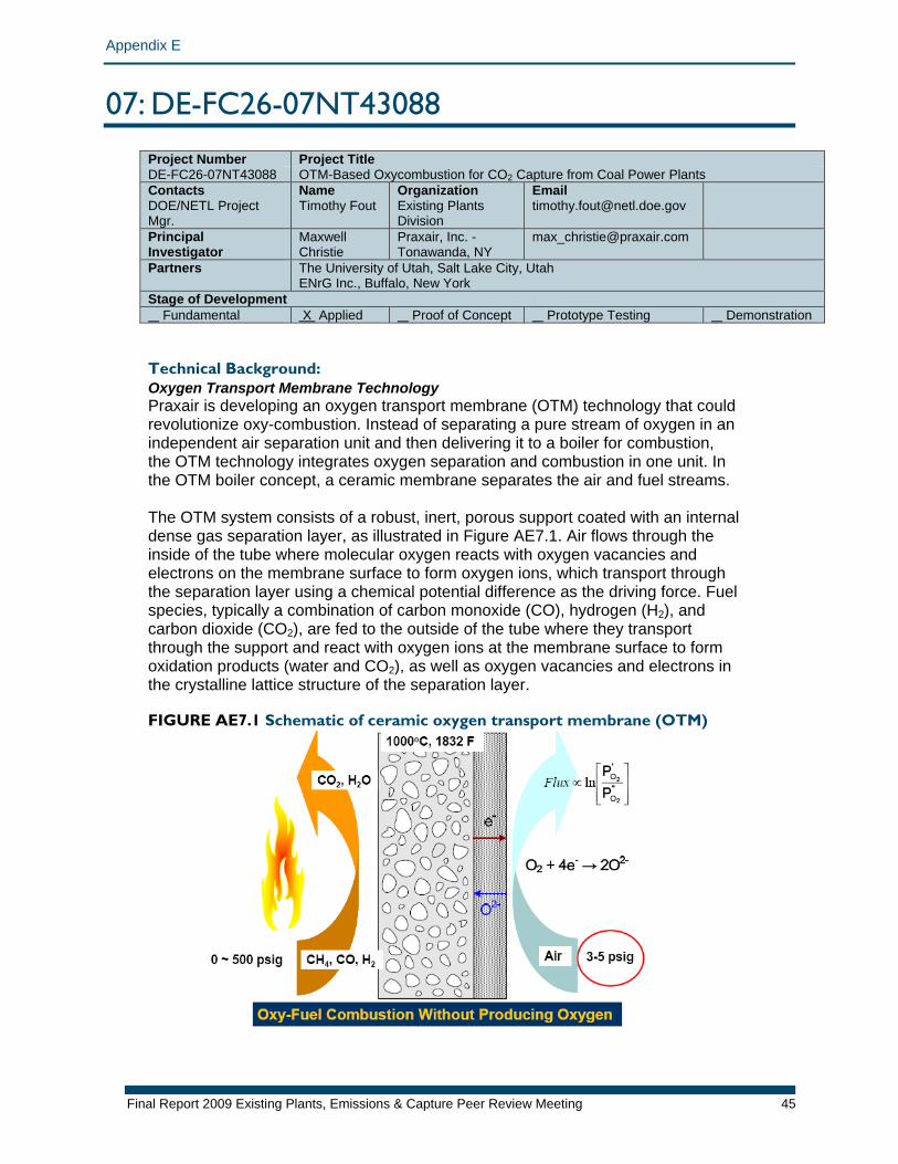
Appendix E
07: DE-FC26-07NT43088 Project Number Project TitleDE-FC26-07NT43088 OTM-Based Oxycombustion for CO2 Capture from Coal Power Plants Contacts Name Organization Email DOE/NETL Project Mgr.
Timothy Fout Existing Plants Division
Principal Investigator
Maxwell Christie
Praxair, Inc. - Tonawanda, NY
Partners The University of Utah, Salt Lake City, Utah ENrG Inc., Buffalo, New York
Stage of Development Fundamental X Applied Proof of Concept Prototype Testing Demonstration Technical Background: Oxygen Transport Membrane Technology Praxair is developing an oxygen transport membrane (OTM) technology that could revolutionize oxy-combustion. Instead of separating a pure stream of oxygen in an independent air separation unit and then delivering it to a boiler for combustion, the OTM technology integrates oxygen separation and combustion in one unit. In the OTM boiler concept, a ceramic membrane separates the air and fuel streams. The OTM system consists of a robust, inert, porous support coated with an internal dense gas separation layer, as illustrated in Figure AE7.1. Air flows through the inside of the tube where molecular oxygen reacts with oxygen vacancies and electrons on the membrane surface to form oxygen ions, which transport through the separation layer using a chemical potential difference as the driving force. Fuel species, typically a combination of carbon monoxide (CO), hydrogen (H2), and carbon dioxide (CO2), are fed to the outside of the tube where they transport through the support and react with oxygen ions at the membrane surface to form oxidation products (water and CO2), as well as oxygen vacancies and electrons in the crystalline lattice structure of the separation layer. FIGURE AE7.1 Schematic of ceramic oxygen transport membrane (OTM)
Final Report 2009 Existing Plants, Emissions & Capture Peer Review Meeting 45

Appendix E
OTM-Based Oxy-combustion Process Several process concepts incorporating ceramic OTMs are being explored to understand their impact on process economics. One process concept under development is shown in Figure AE7.2. In this process, coal is first gasified in an oxygen-blown gasifier to generate coal-derived synthesis gas (syngas). The syngas is optionally reacted in an OTM partial oxidation reactor to raise its temperature. The hot syngas is expanded to recover power. Depending on the gasifier operating pressure, there could be more than one stage of expansion in the process. After the syngas is expanded to slightly above the ambient pressure, it is sent to the OTM boiler. Within the OTM boiler, syngas is first passed over an array of OTM tubes. Air is preheated by heat exchange with the oxygen-depleted air and then passed on to the inside of the OTM tubes. Oxygen from the air transports across the membrane and reacts with the syngas. Because the rate of oxygen transport is limited by the availability of the membrane area, the oxidation of syngas will take place over a large area (the OTM zone) within the boiler. As the syngas gets oxidized, the driving force for oxygen transport will decrease and the required membrane area will increase. For practical reasons, the OTM will be used to supply oxygen to the fuel side until 80%–90% fuel utilization is achieved. The remainder of fuel will be combusted using oxygen supplied from the cryogenic air separation unit. The thermal energy released within the boiler is used for steam generation. In the OTM zone, steam tubes will be interspersed with the OTM tubes such that the temperature is maintained at the optimum level for membrane performance. After the fuel is completely oxidized with externally supplied oxygen, the flue gas will pass through a convective section of the boiler for further steam generation and boiler feed water preheating. The flue gas exiting the boiler is processed according to a purification process proposed for a conventional oxy-fuel technology. FIGURE AE7.2 OTM-based process for power generation with CO2 capture
Relationship to Program:
Final Report 2009 Existing Plants, Emissions & Capture Peer Review Meeting 46
This project will support important advances within the oxy-combustion focus of the CO2 capture and compression area of the NETL EPEC program. Unit power consumption for supplying oxygen (kilowatt-hour/ton of oxygen [O2]) to the oxy-fuel
Appendix E
combustion process is reduced by >70%. This results in a step change in efficiency improvement and decrease in cost of electricity for a power plant that enables CO2 capture. Additionally, in a conventional oxy-fuel process, the efficiency of the power plant will drop by 9%–10%. Due to such a large efficiency penalty, the cost of CO2 avoided will be 25%–30% higher than the cost of CO2 captured. In comparison, the efficiency drop for the OTM-based power cycle will be only 2%–3%. As a result, the cost of CO2 avoided would be within 10% of the cost of CO2 captured. A secondary benefit of the project is the development of a low-cost oxygen supply system that is applicable to alternative partial oxidation technologies (e.g., natural gas to liquids and renewable fuel generation). Primary Project Goal: The primary goals of this project are to facilitate a step change in the costs associated with oxy-combustion and CO2 capture from coal power plants and to advance Praxair’s OTM technology to a point where it is ready for pilot-scale field testing. Objectives: In Phase I of the project (2–3 years) the primary focus is OTM development. A successful outcome of Phase I shall deliver OTM technology that meets commercial targets for oxygen flux, strength, and reliability. In order to improve the oxygen flux performance of the ceramic membranes, the approach will first identify the rate-limiting steps for the separation, and then address kinetic or mass transport limitations through appropriate materials selection and architecture development. It is important that any modifications made to the membrane materials or architecture do not significantly reduce the strength and robustness of the membrane. Another objective is to ensure that the membranes can be integrated directly in a coal power cycle without the need for extensive and costly removal of contaminants or coal by-products that may chemically react with the membrane and lead to performance reduction and/or failure. To that end, a membrane test installation will be commissioned that has the capability to expose the ceramic membranes to simulated coal gas that contains hydrogen sulfide and carbonyl sulfide, two of the most likely species that could harm membrane performance, at elevated pressure. To fully address membrane stability in a coal-derived fuel, the University of Utah has been contracted to commission a coal reactor that will operate with a commercial coal fuel and that will expose the ceramic membranes to all of the species that could potentially harm them. In order to position the ceramic membrane technology for a future pilot demonstration of the technology, it is important to scale up the physical size of the membranes that can be manufactured and to add additional manufacturing capacity. Developing manufacturing protocols for one-third pilot-size membranes is an important Phase I objective. Initially, Praxair intended to execute this task internally; however, it became apparent that the standard OTM substrate technology that Praxair had developed did not possess sufficient mass transfer qualities to meet performance goals. For that reason, Praxair teamed with ENrG Inc. to implement an advanced substrate technology and solicited additional funding from New York State. An additional key objective of Phase I is to down-select an optimum process integration cycle for the OTM membranes with CO2 capture and to provide a full
Final Report 2009 Existing Plants, Emissions & Capture Peer Review Meeting 47
Appendix E
system and economic analysis of that cycle. The University of Utah has been contracted to assess the technical feasibility of integrating the membranes into an OTM coal reactor. HYSYS and Steam-Pro will be used to model the various process options. Membrane performance data obtained from experiments will be used to develop more accurate cost estimates for OTM equipment. Capital cost of equipment will be scaled from data presented in Electric Power Research Institute reports, and what-if scenarios will be used to evaluate the potential reach of the technology. The design philosophy employed in all the processes is to combine commercially available equipment, with the exception of the OTM technology. In Phase II of the project (1 year), Praxair will scale up the physical size of the OTM to that required for pilot testing and develop an OTM-manufacturing plan through commercialization. Finally, at the close of Phase II, Praxair shall deliver a plan for pilot testing of the technology that shall include the basic engineering design and cost of key pieces of OTM-based equipment, as well as an update to the system and economic analysis of the proposed cycle. Phase I aims to achieve the following objectives:
1. An OTM technology that approaches commercial targets for oxygen flux, strength, and reliability
2. A down-selected optimum process integration cycle for the OTM membranes with CO2 capture and a full system and economic analysis of that cycle
Phase II aims to achieve the following objectives:
1. An OTM technology that meets the flux and reliability targets required to proceed to a Phase III pilot test
2. OTM tubes that have the appropriate dimension and manufacturing yield required to proceed with pilot demonstration
3. Demonstrated technical feasibility of the process selected for the pilot phase 4. Preliminary engineering design layout and cost estimate for a pilot facility that
proves key components of the envisioned technology
Final Report 2009 Existing Plants, Emissions & Capture Peer Review Meeting 48
Appendix E
08: DE-FC26-06NT42811 Project Number Project Title DE-FC26-06NT42811
Jupiter Oxycombustion and Integrated Pollutant Removal for the Existing Coal Fired Power Generation Fleet
Contacts Name Organization Email DOE/NETL Project Mgr.
Timothy Fout
Existing Plants Division
Principal Investigator
Mark K. Schoenfield
Jupiter Oxygen Corporation
Partners National Energy Technology Laboratory, CoalTeck LLC Stage of Development Fundamental X Applied Proof of
Concept Prototype Testing Demonstration
Technical Background: The underlying technology concept for this project is the application of a unique and efficient oxy-fuel combustion process, which has been used in aluminum melting for over a decade, in combination with a pollutant removal system that captures carbon dioxide (CO2) and also recovers heat and returns it to the boiler. Oxy-coal combustion for power generation is relatively well known, having been explored since the 1980s as a method for reducing nitrogen oxides (NOx). However, there is a lack of detailed technical knowledge needed to commercialize the process. Specifically, there is limited information on heat and mass transfer in an oxy-coal system; materials interaction with oxy-fuel combustion products; systems-level interactions for energy recovery; effects of infiltration/exfiltration; transient operation (start-up, shutdown); burner design; boiler design; materials selection; and reliable modeling. At the present time, there is no clear path to the Existing Plants, Emissions & Capture Program goal of a power plant with a carbon capture and sequestration system that can capture >90% of the carbon from the fuel while increasing the cost of delivered energy services by less than 35%. The Jupiter Oxygen Hammond test facility will provide specific information to determine if oxy-coal combustion has the potential to meet these goals. NETL is active in producing advanced computer programs to aid design and deployment of new technologies. The NETL Office of Research and Development (ORD) Computational Science Division (CSD) is working with the ORD Process Development Division to better simulate oxy-fuel flames and will use data obtained from the Jupiter Oxygen Hammond facility. The salient features of Jupiter Oxygen’s process include the use of oxygen instead of air; high flame temperature (“undiluted” flame is not cooled with recirculation or nitrogen); increased radiant heat transfer; reduced fuel input to match current thermal requirements in the radiant zone; flame shaping; staged oxygen burners; near stoichiometric combustion (i.e., low excess oxygen) with the proper mixing of oxygen and fuel; and use of standard oxygen combustion burner materials, such as high-temperature refractory tip (rather than lower-temperature air combustion) materials such as steel. The Integrated Pollutant Removal (IPR) system, developed by NETL, captures combustion vapors and prepares them through pressurization for delivery outside
Final Report 2009 Existing Plants, Emissions & Capture Peer Review Meeting 49
Appendix E
the plant fence line. Heat available from intake condensation and compressor intercooling/aftercooling is returned to the power plant thermal cycle. In the process, pollutants are removed with the condensate at each cooling step and/or kept in the CO2. The NETL IPR technology is most effective when conditioning a concentrated (without significant nitrogen [N2] or excess oxygen) flue gas stream. This makes Jupiter’s Oxygen’s oxy-fuel combustion and IPR technologies complementary. Previous Jupiter Oxygen capture-related work with NETL showed that this combination of technologies could effectively capture CO2 from the combustion of coal. Combustion gas tests in a 75 kilowatt (kW) unit showed NOX levels at 0.088 lb/million British thermal units, without any back-end NOx removal equipment. With the addition of the IPR system, more than 80% of the CO2 was captured at pressures showing that greater than 95% capture is feasible; additionally, 99%+ of the sulfur oxides (SOx) and particulates were captured. Particle-bound mercury was removed from the flue gas, and mercury vapor was concentrated throughout the process, indicating that approximately 90% of the mercury could be captured with proven technologies. Initial experimentation indications on the new IPR equipment were positive. Another issue being addressed at Hammond is the reliability of oxy-fuel power plants. The power generation industry will not accept a solution that significantly reduces the availability of power plants. Materials investigations at Hammond will help to better understand the impact of oxy-fuel combustion on power plant components over time. There are open questions about the corrosivity of oxy-fuel combustion products of high-sulfur coals. The NETL ORD Office of Materials Performance will investigate materials in the Hammond test facility and the interaction of the materials with the ash and slag produced there. The primary focus of the oxy-coal burner test facility will be full-scale testing of a 15 megawatt thermal (MWth) coal burner suitable for use in a 25 megawatt electric (MWe) power generation system. The Jupiter Oxygen Hammond test facility has been designed to address a broad spectrum of the issues that will enable NETL to demonstrate the ability to meet the Existing Plants, Emissions & Capture Program goals. The test facility is designed to be able to better understand the following:
• Burner design (NOx levels, flame stability, unburned carbon, excess oxygen, carbon monoxide [CO] generation, coal velocity, burner tip material, and oxygen staging)
• Heat and mass transfer issues in retrofit and new design of oxy-coal fired power plants (interaction of flue gas recycle rates and radiant heat transfer)
• Materials interaction in the oxy-coal combustion and capture environment • Capture through IPR—an integrated approach for multiple pollutant removal • Slag and ash behavior in the oxy-fuel environment • Compression technology for mixed supercritical products • Energy recovery in an integrated oxy-coal/IPR power plant • Measurement for verification of NETL ORD computer simulations of oxy-coal
power plants; improved simulations can accelerate development of oxy-fuel/IPR systems
• Infiltration effects (the effect of air infiltration on capture efficiency and quality)
• Chemistry of captured combustion products
Final Report 2009 Existing Plants, Emissions & Capture Peer Review Meeting 50
Appendix E
This will speed up the analysis of oxy-combustion/IPR pilot-scale unit processes for capture to meet the goal set in the Carbon Sequestration Technology Roadmap and Program Plan. Without a facility such as this, scale-up will be extremely difficult. Impact of Jupiter Oxygen Flame Temperature Differences Most oxy-fuel systems tend to try to mimic the flame and other temperature and flow fields in existing boilers. The Jupiter Oxygen undiluted, high flame temperature approach [approximately 5,000°F] has a higher concentration of oxygen in the burner for a substantially hotter flame than air firing or oxy-fuel firing (which has flame temperatures approximately equal to those of air firing). Jupiter Oxygen’s hotter flame increases radiant heat transfer to the boiler walls. It is important to the project to carefully measure the heat transfer from the flame to the boiler walls for use in future engineering estimates of burner performance. The primary indicators of radiant heat transfer are chordal thermocouples, which are used to measure radial metal temperatures as a basis for calculating heat flux through the tube walls. The methodology measures the temperature change across the wall of the tubes to indicate the heat flux through the wall. As a baseline, the tube characteristics (including internal scale and material of construction) are being determined by NETL. Materials-Related Issues There are potentially significant materials-related issues that this project will serve to better define. Potentially higher thermal loading (i.e., heat transfer) in the radiant zone tends to be viewed as a potential problem by the power generation industry. Jupiter Oxygen looks at this as a potential advantage, as long as the heat flux from the hot flame to the boiler walls can be carefully characterized and designed into new boiler system improvements. In retrofit applications, the heat transfer to each heat transfer surface (water walls, superheaters, reheaters, economizer, and oxidant preheater) must be matched to existing heat transfer to surfaces in order to minimize modifications. The ability to tailor heat transfer with minimal changes in boiler retrofits is dependent on understanding the heat transfer and ensuring that it meets the requirements of the existing heat transfer surfaces or that there are methods for ensuring that final steam temperature meets the requirements of the steam turbines. The interaction of slag, ash, and SOx with boiler materials is also an important area for investigation. Slag, ash, and SOx interaction with the boiler materials will be an important aspect of this investigation. In order to characterize the boiler materials, samples of the boiler tubes have been removed for destructive testing at NETL prior to the start of operation. These initial tubes serve as a baseline for future sampling and testing. The tubes will be characterized using standard metallurgical procedures to include strength, hardness, impact testing, tensile testing, microscopic analysis, corrosion state at sampling, microstructure of the weld heat–affected zones, and other tests indicated during standard testing. Tubes will be sampled as operations proceed to determine changes in the metallurgy of the exposed boiler tubes. Combustion Product Monitoring In air-fired systems, there is no need to measure the N2 content of combustion products. In an oxy-fuel system, it is important to measure (or calculate) N2 in the system (elevated N2 indicates air in-leakage). Combustion product composition monitoring determines CO2, H2O, argon, oxygen, sulfur dioxide, N2, mercury, and particulate matter (PM). The solid combustion products, including ash and slag,
Final Report 2009 Existing Plants, Emissions & Capture Peer Review Meeting 51
Appendix E
are sampled and characterized for composition and mineralogy, and will be used in standard testing to determine the corrosion potential in an oxy-fuel environment. Experimental Design The goal of instrumentation, data collection, and data analysis is the characterization of the processes and equipment performance. To meet these requirements, standard accepted approaches promulgated by the American Society of Mechanical Engineers, IEEE, American Society for Testing and Materials, American National Standards Institute, International Organization for Standardization, and National Institute of Standards and Technology are being used. There are two major components of this research system: the oxy-fuel burner test portion and the IPR test portion. They are coupled in that the IPR experimental system uses a slipstream of the combustion products from the oxy-fuel burner test system. The burner test facility will produce steam (just as in a power plant application). However, the steam will not be used for power generation. Because the steam is not used in power generation, the steam measurements serve to characterize the heat transfer performance of the oxy-fuel burner. The boiler is heavily instrumented, and the measurements of water, steam, combustion products, and heat transfer will characterize the transfer of heat from the flame to the steam. Specific Measurement Approaches Temperature. Most temperatures are taken with special limits of error thermocouples, using the published special error limits as the expected uncertainty. Where temperatures are critical, more accurate methods, such as a platinum resistance thermometer, have been substituted. A specific example of a difficult measurement is the metal temperature of boiler tubes. In the case of boiler metal temperatures, the Babcock and Wilcox approach of chordal thermocouple insertion is used. In this method, a fine thermocouple is threaded through chordal holes drilled in the boiler tube wall and, where it comes to the surface, a weld bead is peened over the thermocouple to protect it. In this way, a fine thermocouple can be threaded to a position just below the exposed surface of the boiler tube and accurate measurements of the metal temperature can be made. Chordal temperature measurements are made at locations in the boiler tubes to better understand heat transfer from the flame to the tube walls. This type of measurement is not typical of measurements taken in a power generation boiler because the flame heat transfer characteristics are better known for air-fired systems. Combustion product composition. The combustion products in an oxy-fuel system are different from those in an air-fired system. The increase in CO2 and H2O and the decrease in N2 produce a gas with different infrared properties and a different environment for potential corrosion. To better understand the results of the burner experiments, it is necessary to characterize the combustion products. Coal, slag, ash, and PM characterization. Physical samples have been taken of the coal, slag, and ash, as well as filtered samples of the fine particulates found in the combustion products. There is very little information on the characteristics of oxy-fuel combustion products, and the intent is to determine if there will be problems inherent in these combustion products. Samples will be screened for issues that
Final Report 2009 Existing Plants, Emissions & Capture Peer Review Meeting 52
Appendix E
may lead to future activities in this area. The normal analyses are performed on all coal deliveries to the plant (proximate, ultimate, and ash). However, there has also been a characterization of the mineralogy of the coal samples. It is these minerals that are transformed into ash and slag. Because the temperatures of the transformation and the atmosphere will be different in an oxy-fuel system, the team will have the opportunity to determine if the resulting slag and ash is significantly different from that of an air-fired sample. NETL-Identified Areas of Research NETL has begun a modeling process to identify and rank enabling technologies that have significant impacts on pulverized coal oxy-fuel systems. Key research areas affecting heat rate include the following: Flue Gas Desulfurization during recycle. An important question influencing the designs of oxy-fuel power plants is the role of SOx in the boiler. This is primarily a materials issue. The fraction of SOx in an oxy-fuel boiler is higher than that in an air-fired system (using the same fuel) because the incoming air has about 78% N2, which dilutes the sulfur in the fuel. In an oxy-fuel system, the oxidizer comes in as pure oxygen and does not dilute the fuel sulfur as much as air. The result is higher SOx in the oxy-fuel boiler and much less N2. Both destructive testing and nondestructive testing of boiler materials will enable both Doosan Babcock and NETL to observe the effects of the low N2, high SOx environment. The concern has to do with high SO2 content in the boiler and its interaction with standard boiler materials as well as the potential for a reducing environment. No one has reliable data on the effect of this high-sulfur environment in materials of construction and, consequently, to maintain the combustion products within the scope of known concentrations, designers are proposing Flue Gas Desulfurization (FGD) as in intermediate step in the flue gas recirculation process. The Hammond facility will be used to test a high-sulfur coal and introduce standard materials of construction into the boiler atmosphere. There is an energy loss, if FGD is used for recycle, because energy that would otherwise be recycled is lost in the FGD process. Regarding standard materials and a high SO2, low N2 environment, there have been no tests to determine the threshold at which alternate materials of construction will be needed. Boiler material samples will be taken throughout the testing, and test materials will be introduced to the environment. Measurements of the metal conditions (slag, fouling, temperature, metal thickness, and other parameters) will provide data for further NETL computer program development. Heat recovery. One advantage of oxy-fuel systems is that the mass of the exhaust is significantly less than that of an air-fired system due to the absence of N2. Another advantage is that the sensible and latent energy that is normally lost up the stack has to be dealt with during the CO2 capture process. In the IPR CO2 capture approach, the sensible and latent heat of the flue gas is partially recovered and used to heat the boiler condensate. In like manner, heat of compression is partially recovered by using boiler feedwater to intercool the stages of compression. The Hammond IPR section will recover energy to determine how costly the energy recovery is. Initial systems analysis shows recovery of heat to be a very important aspect of capture and compression. Recirculation. The amount of recirculation needed to temper the burner flame and approach the conditions needed to match heat transfer in a retrofit system is
Final Report 2009 Existing Plants, Emissions & Capture Peer Review Meeting 53
Appendix E
generally thought to be in the range of 28%–38% O2 content. Retrofit is significantly different from green-field design because the boilers and heat transfer surfaces are already defined. Recirculation is one of the mechanisms for controlling heat transfer in the boiler system, and the Hammond Test Facility is designed to measure temperatures in the boiler heat transfer surfaces using a combination of chordal thermocouples and traditionally placed thermocouples to understand the heat transfer from the flame to the boiler water. Measurement of thermal responses to changes in recirculation will be an important part of test facility activities. Excess O2. In an oxy-fuel system, the combustion oxygen is extracted from the air at a significant energy cost. Excess O2 creates a wasted cost unless it is necessary for sufficiently complete combustion of coal. The low end of the approach to stoichiometric oxy-fuel flames has not been well defined for oxy-coal systems. If the excess O2 in the combustion products can be reduced from levels in air-fired systems, it will save the power plants in the cost of air separation. The burner test facility will test the limits of O2 ratios and monitor combustion products, including carbon. Testing will determine whether less than 3% excess O2 can maintain the same CO levels as 3% excess oxygen (normal air firing). Air infiltration. There is debate about the requirement of positive or negative pressure in pulverized coal boilers. The concern about elevated CO2 and possible elevated SOx levels in the combustion products has resulted in the suggestion that boilers that are presently running at positive pressure using air might have to run at negative pressure due to safety concerns. The result of running at negative pressure is that air leaks into the system wherever there is a leak. When running at positive pressure, combustion products can leak out. In either case, it is more important to seal an oxy-coal system with carbon capture than it is to seal a conventional boiler. One of the results of positive-pressure exfiltration is that there is a loss of CO2 to the atmosphere as well as the possibility of toxic fumes in the boiler vicinity. In the case of negative pressure, the leakage of air into the system adds N2 to the boiler environment. One problem with added N2 is that it makes separation more difficult. Also, when the inert gases go up, the fraction of CO2 lost during the purification process goes up. The Hammond facility is designed to allow measured air in-leakage which will be measured in the exhaust product along with the changes in N2 levels in the system. This will provide for determining allowable leakage and related engineering issues. The analysis will be closely coordinated with the ongoing efforts to determine the purity required for multiple sequestration scenarios. Materials performance in an oxy-fuel combustion environment. One of the questions for oxy-fuel combustion is the compatibility of traditional power plant materials with the oxy-fuel combustion products. This test facility will examine the effect of an oxy-coal flame on materials. The tests will not be as long term as an actual power plant installation, but will give information on the combustion environment, metal thermal responses, and ash and slag composition. This information will be used in ongoing NETL longer-term controlled materials experiments aimed at accelerated materials testing. This will include metal samples suspended in the combustion area and samples removed from the boiler tubes both before oxy-coal combustion and at regular intervals during testing. Combining the materials data with the extensive chemical and thermal monitoring will allow better understanding of the oxy-coal combustion environment for materials evaluation.
Final Report 2009 Existing Plants, Emissions & Capture Peer Review Meeting 54
Appendix E
The project testing will lead to developmental information for scaling up oxy-fuel burners and actual oxy-coal for use in a planned 25 MWe power plant retrofit. In addition, the IPR testing will refine IPR development, including for the same planned retrofit project. Further, information generated will advance oxy-fuel combustion CO2 capture with regard to heat transfer, safety, pressure, and materials issues. Relationship to Program: This project will support important advances within the oxy-combustion focus of the CO2 capture and compression area of the NETL EPEC program. This project relates to performance goals indicated in the Carbon Sequestration Technology Roadmap and Program Plan for greater than 90% CO2 capture from the flue gas with projected costs close to the current cost of electricity (consistent with the goal of not more than a 35% increase for capture, transport, and sequestration in retrofit applications). It is understood that these goals apply to the post-combustion and oxy-combustion projects being developed by the Existing Plants, Emissions & Capture Program. In addition, the product of work (burners) from this project is needed for a planned 25 MWe power plant retrofit that can be completed as planned to support DOE’s goals. The benefits of the successful completion/application of this research are as follows. Oxy-coal burners will be tested at a larger scale that can be retrofitted to a 25 MWe power plant on the grid. This research also will advance oxy-fuel combustion with carbon capture pathway, and 99%+ capture of NOx, 99%+ capture of SOx, 99%+ capture of particulate matter including 80%+ of PM2.5, and 90%+ capture of mercury. Primary Project Goal: The primary project goal is the development of scaled-up oxy-fuel burners and further process refinement of IPR for an actual retrofit of a 25 MWe power plant on the grid. Objectives: The purpose of this project is (1) the development of oxy-fuel burners that are consistent with the Jupiter Oxygen oxy-fuel process, (2) the capture of CO2 using the Jupiter Oxygen combustion process with the IPR technology developed by NETL, (3) the combination of the technologies to meet the DOE Existing Plants, Emissions & Capture Program requirements for cost of electricity, and (4) data collection on material performance in an oxy-fuel combustion environment. This project includes the design, procurement, construction, installation and operation of a 15 MWth (scale per actual burner needed for planned 25 MWe retrofit) burner test facility with a 50 kW (slipstream) IPR unit in Hammond, Indiana. The test plan has been developed with initial input and ongoing feedback from NETL. Test plan approval is completed prior to each phase of testing operation. One milestone is a 15 MWth oxy-fuel burner capable of retrofit application. A second milestone is operation of the slipstream IPR system consistent with retrofit application. Coal testing is being performed with the Illinois bituminous coal used by a potential retrofit site in Illinois.
Final Report 2009 Existing Plants, Emissions & Capture Peer Review Meeting 55

Appendix E
Concurrently, the NETL Office of Systems Analyses and Planning, with Jupiter Oxygen, will generate the necessary information (equipment requirements and performance) required as inputs into a systems analysis of Jupiter Oxygen oxy-fuel and IPR technological viability for economic scale-up, either in combination or individually with generic counterparts, and conformance to the DOE Existing Plants, Emissions & Capture Program goals. The NETL ORD CSD is also looking at modeling of this system to verify their models based on these measurements.
Final Report 2009 Existing Plants, Emissions & Capture Peer Review Meeting 56
Appendix E
09: DE-FC26-06NT42747 Project Number Project TitleDE-FC26-06NT42747 Development of Cost Effective Oxycombustion Technology for Retrofitting Coal-
Fired Boilers Contacts Name Organization Email DOE/NETL Project Mgr.
José D. Figueroa
Existing Plants Division
Principal Investigator
Hamid Farzan Babcock & Wilcox Research Center
Partners Air Liquide, Battelle Memorial Institute Stage of Development Fundamental Applied Proof of
Concept X Prototype Testing Demonstration
Technical Background: The key to a strong, stable, and secure economy is readily available, reasonably priced energy. To maintain economic competitiveness and meet growing energy demands, the United States must improve the utilization of its domestic resources. Our vast resources of coal will play a strategic role in electric power production. However, fossil fuel combustion is also a primary contributor of increased greenhouse gas (GHG) emissions. As fossil fuels continue to be the dominant fuel source for electricity generation, reducing carbon emissions by capturing and sequestering carbon dioxide (CO2) from utility boilers is under consideration to reduce these emissions and thereby control overall atmospheric GHG emissions. Development of the technologies that reduce GHG and minimize the cost of electricity (COE) is of a prime interest to the existing coal-fired boilers. Babcock & Wilcox Power Generation Group and Air Liquide teamed to further develop the oxy-combustion technology for retrofit applications in existing coal-fired, wall-firing, and cyclone boilers. The technology involves the replacement of the combustion air by pure oxygen (O2) diluted in recycled flue gases, enabling CO2 capture from coal-fired power plants. It will be applicable with minimal pressure-part modifications to existing boilers. Babcock & Wilcox, Air Liquide, and Battelle will develop a preliminary design and prepare a budgetary cost estimate for the boiler retrofit. Air Liquide will provide the expertise in air separation unit (ASU), flue gas purification, and CO2 compression. Battelle will provide expertise in CO2 transportation and sequestration. Aspen modeling will be used to integrate the ASU, boiler, and CO2 compression train for sequestration. The Aspen model will evaluate various design scenarios that maximize the net plant efficiency and minimize COE. Relationship to Program: This project will support important advances within the oxy-combustion focus of the CO2 capture and compression area of the NETL EPEC program. Since 1999, Babcock & Wilcox and Air Liquide have been active in the development of oxy-combustion for pulverized coal (PC) wall-firing applications. Previous development efforts have been performed with an eastern bituminous coal and a Powder River Basin coal. This project expands the applicability of the technology to lignite firing. In addition, oxy-combustion will be adapted in this program for application to cyclone-equipped boilers: cyclone boilers operate in a slagging mode that requires modifications of oxy-combustion technology before it
Final Report 2009 Existing Plants, Emissions & Capture Peer Review Meeting 57
Appendix E
can be used in these boilers. This project provides a means for CO2 control from existing cyclone boilers. An added benefit of the oxy-combustion process, especially for cyclone boilers, is that it provides reduced nitrogen oxide (NOx) emissions from the boiler. Upon successful completion of this development effort, pilot-scale oxy-combustion test data will be available for application and scale-up to both wall-fired and cyclone boilers that burn bituminous, subbituminous, or lignite coal. This project significantly broadens the applicability of oxy-combustion technology to the existing fleet of coal-fired boilers. The oxy-combustion technology typically concentrates the CO2 to approximately 85% by volume at the boiler exit. Depending on the compression, transportation, and sequestration steps, it may be necessary to further purify the flue gas and increase the CO2 concentration by reducing the water vapor, NOx, and sulfur dioxide (SO2). High-purity (above 99%) CO2 can be recovered via a combined purification and compression train that separates the rest of the gases (e.g., nitrogen [N2], O2, etc). Therefore, in accordance with DOE goals, this project has set a CO2 capture goal of 90% or more, which will be further optimized so that the energy requirement for flue gas purification and the compression train results in the lowest impact on COE. By integrating and optimizing different aspects of oxy-combustion, significant progress towards DOE’s Carbon Sequestration Program goals will be achieved. Oxy-combustion is a proven concept, designed to greatly facilitate the capture and subsequent sequestration of CO2 from existing and new coal-fired boilers. Oxygen is mixed with recycled flue gas to replace the normal combustion air at the burner. The O2 is supplied by an air separation unit located either on-site or off-site. The volume of flue gas leaving the boiler is considerably smaller than the conventional air-fired volume and consists primarily of a concentrated stream of CO2 available for capture and subsequent carbon sequestration without the need for expensive and energy-consuming separation systems. Primary Project Goal: The primary goal of this project is to further develop the oxy-combustion technology for commercial retrofit in existing wall-fired and cyclone boilers by 2012. To meet this goal, a two-phase research project has been developed that includes pilot-scale testing and a full-scale engineering and economic analysis. Objectives: Phase I objectives include the following:
• Evaluate the effect of coal rank that is currently used in existing boilers (i.e., bituminous, subbituminous, and lignite) in an oxy-combustion design
• Determine the equipment requirements for the boiler island, including flue gas purification, CO2 compression, transportation, and storage for different coals and combustion systems (cyclone and wall-fired)
• Investigate the potential for multipollutant (NOx, SO2, and particulate) reduction
Phase II objectives are as follows:
• Conduct an engineering and economic assessment of the technology for commercial-scale retrofit and greenfield application for cyclone and wall-fired units
Final Report 2009 Existing Plants, Emissions & Capture Peer Review Meeting 58
Appendix E
• Assess CO2 control cost reductions via the integration of ASU flue gas purification, CO2 compression train, CO2 transportation, and sequestration
• Evaluate the impact of oxy-combustion implementation on net power production and COE for cyclone and wall-fired applications
Work Performed Specification of Flue Gas Purification, Compression, Transportation, and Sequestration The optimization of the flue gas purification train and boiler enable cost savings. The key is to view the whole process of O2 separation, coal combustion, steam generation, flue gas purification (if required), transportation, and sequestration together. Cost savings can be realized by optimizing the flue gas handling through two fundamental options: one is to compress the flue gas and inject it directly into a suitable geologic formation; another is to separate gas components that may not be advantageous to long-term injection. The former case will require less environmental control equipment (e.g., sulfur oxide [SOx] and NOx removal). However, the feasibility of this option will require rigorous reservoir and geochemical modeling. In particular, noncondensable gases, such as N2 and O2, may affect the subsurface processes by creating a multiphase flow situation that may reduce injectivity or reduce the capacity of the aquifer for CO2 of the lifetime of the power plant. If it is determined that additional purification is needed to remove certain impurities such as excess O2, N2, or other post-capture impurities that may affect compression, handling, or regulatory requirements, then the equipment for scrubbing these impurities will need to be evaluated. The project approach was to (1) determine the flue gas composition from an oxy-fired boiler, (2) review the pipeline gas requirement, (3) determine the steps that are required for the flue gas purification, and (4) perform reservoir and geochemical modeling to ensure the feasibility of sequestering the flue gas. Babcock & Wilcox used its Aspen oxy-combustion model to predict the gas composition from three coals. For this initial analysis, SO2 was not scrubbed and a conservative 10% air infiltration was assumed. The recycled gas was cooled down to 135°F, resulting in approximately 17% moisture in the recycle gas. Battelle investigated the impacts of oxy-combustion flue gas impurities on transmission and storage operations. The two fundamental options considered were to (1) compress the flue gas and inject it directly into a suitable geologic formation, and (2) separate gas components that may not be advantageous to long-term injection. Battelle reached the following conclusions:
• Co-sequestration of CO2 and SO2 appears to be technically feasible in many deep saline reservoirs, but the injection lifetime of these reservoirs could be reduced if precipitation reactions take place.
• In carbonate-rich formations, sulfate could be a problem. However, no such problem would likely exist in pure sandstone of feldspar-rich formations. Results of this preliminary modeling study indicate that screening must be done to identify potential problems with the injection of flue gas.
• Precipitation of a solid phase, such as calcium sulfate (anhydrite), is influenced to a much greater extent by dissolution of carbonate minerals in the storage formation than by addition of sulfate in the form of SO2 in the injection gas. Therefore, even if anhydrite precipitation is likely to occur in a
Final Report 2009 Existing Plants, Emissions & Capture Peer Review Meeting 59
Appendix E
formation where certain mitigating conditions exit that would minimize the impact on injectivity, it still may be unnecessary to scrub SO2 from the flue gas because of the minor effect of SO2 on precipitation. This is an important observation and needs to be explored in more detail.
• In some reservoirs, storage space may be so limited that it is necessary to remove N2 and O2 to maximize the storage capacity. Occupation of pore space and reduction in permeability were not investigated during this reporting period, but they will be evaluated at a later time.
Air Liquide focused its efforts on the flue gas purification and compression train. The goal of this task was to develop a flue gas compression and purification train that processes flue gas from the boiler unit to recover at least 90% CO2 (DOE target) at a composition suitable for sequestration. This task was complicated by the fact that no clear definition yet exists for a “sequestration-ready” gas stream. For the purpose of purification, a “sequestration-ready” gas stream was defined as follows: A “sequestration-ready” gas stream is the product of a compression and purification train that contains at least 90% of the CO2 present in the feed stream at a total pressure of 175 bar (~2,540 pounds per square inch) and a temperature of 95°F. This stream also contains no more than 30 lb of water [H2O] per million standard cubic feet [MMscf] of CO2 (equivalent to 600 parts per million [ppm]). The above specification on water concentration is identical to the Kinder Morgan specification for pipeline transport of CO2. It is hoped that this stringent specification on H2O will result in less stringent specifications on acid-producing gases like SOx and NOx for pipeline transport and sequestration. Currently, no restrictions are placed on any other components in the gas stream. The basic process developed for processing flue gas to “sequestration-ready” specifications is as follows:
1. Compression of the wet flue gas 2. Drying of the flue gas at the outlet of the “wet compression” step 3. Flue gas purification (if considered) 4. Compression of the dry product gas to a pressure at which it condenses at 200°C
(68°F) 5. Pumping of the condensed product to pipeline pressure
Three processes were designed, optimized and compared to arrive upon the process with the least specific energy requirement:
A. Compression and drying only. In this process, flue gas is compressed and dried to obtain a gas stream with 30 lb H2O/MMscf CO2 at the desired pressure. This process corresponds to a case of 100% CO2 recovery.
B. Partial condensation. In this process, flue gas is compressed, dried, and then purified using a partial condensation scheme with two vessels in series to recover 90% of the CO2 in the feed stream. The purified stream is then compressed, condensed, and pumped to the final product pressure.
C. Partial condensation and distillation. This process is an extension of process b. In this process, in addition to partial condensation, distillation is used to reduce O2 in the purified stream to 1 ppm. The purified stream, containing 90% of the CO2 from the feed stream, is then compressed, condensed, and pumped to the final product pressure.
Final Report 2009 Existing Plants, Emissions & Capture Peer Review Meeting 60
Appendix E
Final Report 2009 Existing Plants, Emissions & Capture Peer Review Meeting 61
The compression-only case (A) provides 100% CO2 recovery while the purification cases (B and C) are targeted to achieve 90% purity. Interestingly, for a product pressure of 175 bar, the purification schemes require lower specific energy than the compression-only scheme for all three coals: cases B and C require 3% and 6% lower specific energy, respectively, than case A. Thus, the purification schemes provide significant enhancement in CO2 purity with lower energy requirement. Up to 20% power could be saved if the air infiltration can be reduced by 50%. The partial condensation and distillation process (case C) requires lower specific energy than partial condensation alone (case B) over the entire range of product pressures considered. At the lower end of the product pressure range, the compression-only process demands the lowest specific energy, while at the top end of the range, it requires the highest specific energy. The following conclusions were reached:
• Coal rank does not have a significant effect on the extent of CO2 purity achievable in the product stream at 90% CO2 recovery by either of the purification processes considered in this study.
• The specific energy required by each process is similar for North Dakota lignite and decker coals and slightly higher for Illinois #6 coal due to the higher amount of non-CO2 gas components in the flue gas relative to CO2 for this coal. The two purification processes provide a significant performance improvement over the compression-only process at 175 bar product pressure because they significantly increase the CO2 purity in the product with a lower specific energy requirement. Among the purification cases, the partial condensation and distillation scheme provides the highest CO2 purity in the product stream at the lowest specific energy for all three coals, for a product pressure of 175 bar. It must be noted that these conclusions are based on the current level of optimization of the purification designs. The net specific energies of the two purification processes are not very different (2% vs. 5%), and it is not inconceivable that future improvements in design might change the relative order of energy requirements of these processes.
• The distillation column in case C achieves high CO2 purity in the product mainly by rejecting air gases; SO2 and nitrogen dioxide are not separated from CO2 in the column.
• Excess air infiltration results in an increase in specific energy. If N2 in the flue gas can be reduced by 50%, it can result in 15%–18% savings in specific energy, depending upon the compression and purification scheme.
• The final product pressure has a bearing on the determination of the least energy-intensive process. For all three coals, the compression-only process has the lowest specific energy below about 120 bar. Above a product pressure of 120 bar, the partial condensation and distillation process has the lowest specific energy. At lower air infiltration, the partial condensation and distillation process becomes less energy-intensive than the compression-only process at lower product pressure.
Engineering Feasibility and Economic Analysis The scope involves performing an engineering and economic evaluation of oxy-combustion on two plants: (1) a PC boiler, and (2) a cyclone boiler. The data-gathering for selection of a cyclone boiler has been started. The project team has analyzed several cyclone plants based on the following criteria:
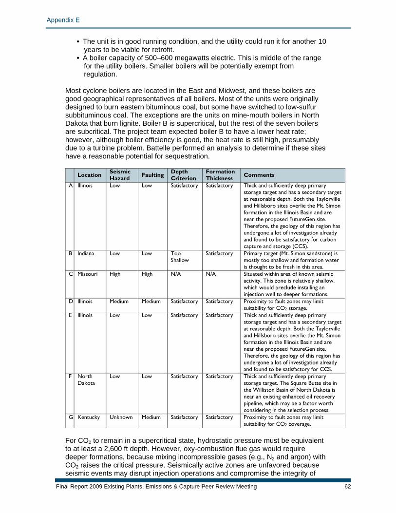
Appendix E
Final Report 2009 Existing Plants, Emissions & Capture Peer Review Meeting 62
• The unit is in good running condition, and the utility could run it for anotheye
r 10 ars to be viable for retrofit.
oilers will be potentially exempt from
located in the East and Midwest, and these boilers are ood geographical representatives of all boilers. Most of the units were originally
sites
• A boiler capacity of 500–600 megawatts electric. This is middle of the range for the utility boilers. Smaller bregulation.
Most cyclone boilers aregdesigned to burn eastern bituminous coal, but some have switched to low-sulfur subbituminous coal. The exceptions are the units on mine-mouth boilers in North Dakota that burn lignite. Boiler B is supercritical, but the rest of the seven boilers are subcritical. The project team expected boiler B to have a lower heat rate; however, although boiler efficiency is good, the heat rate is still high, presumably due to a turbine problem. Battelle performed an analysis to determine if these have a reasonable potential for sequestration.
Location Seismic Hazard Faulting Depth
Criterion Formation Thickness Comments
A Illinois Low Low Satisfactory Satisfactory Thick and sufficiently deep primary and has a secondary target
rville
y
storage targetat reasonable depth. Both the Tayloand Hillsboro sites overlie the Mt. Simon formation in the Illinois Basin and are near the proposed FutureGen site. Therefore, the geology of this region has undergone a lot of investigation alreadand found to be satisfactory for carbon capture and storage (CCS).
B Indiana Low Low Too Shallow
Satisfactory Primary target (Mt. Simon sandstone) is mostly too shallow and formation water is thought to be fresh in this area.
C Missouri High High N/A N/A Situated within area of known seismic activity. This zone is relatively shallow, which would preclude installing an injection well to deeper formations.
D Illinois Medium Medium Satisfactory Satisfactory Proximity to fault zones may limit suitability for CO2 storage.
E Illinois Low Low Satisfactory Satisfactory Thick and sufficiently deep primarystorage target and has a secondaryat reasonable depth. Both th
target
y
e Taylorville and Hillsboro sites overlie the Mt. Simon formation in the Illinois Basin and are near the proposed FutureGen site. Therefore, the geology of this region has undergone a lot of investigation alreadand found to be satisfactory for CCS.
F North Dakota
Low Low Satisfactory Satisfactory Thick and sufficiently deep primary storage target. The Square Butte site in the Williston Basin of North Dakota is near an existing enhanced oil recovery pipeline, which may be a factor worth considering in the selection process.
G Kentucky Unknown Medium Satisfactory Satisfactory Proximity to fault zones may limit suitability for CO2 coverage.
For CO2 to remain in a supercritical state, hydrostatic pre ent
at least a 2,600 ft depth. However, oxy-combustion flue gas would require
se seismic events may disrupt injection operations and compromise the integrity of
ssure must be equivaltodeeper formations, because mixing incompressible gases (e.g., N2 and argon) with CO2 raises the critical pressure. Seismically active zones are unfavored becau

Appendix E
Final Report 2009 Existing Plants, Emissions & Capture Peer Review Meeting 63
the seal above the storage reservoir. To be considered an acceptable location, the site must overlie at least one storage formation that meets depth requirements to maintain a supercritical fluid state. The formation is thick (>50 ft) and has moderato high permeability (not determined for these seven locations at this time). Access to a secondary storage reservoir is considered advantageous. As a result of this analysis, plant A is considered the best choice among cyclone boilers from a geological storage perspective. Plant B is consid
te
ered to be a more hallenging location, because the site is shallower and there is a possibility of
cfresh water in the vicinity. These constraints could preclude CO2 injection near plant B based on risk. However, a more in-depth analysis must be done before speculating on an outcome. From a sequestration point of view, three units areacceptable, three are unacceptable, and unit B is marginal.
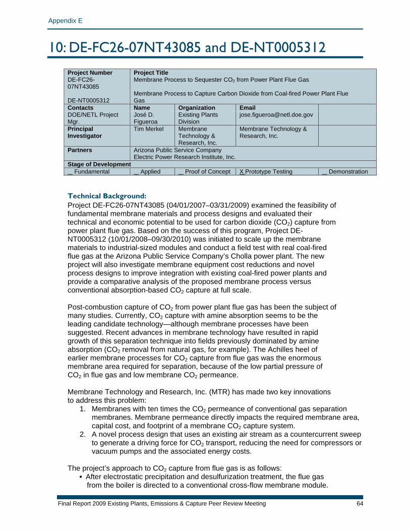
Appendix E
10: DE-FC26-07NT43085 and DE-NT0005312 Project Number Project TitleDE-FC26-07NT43085 DE-NT0005312
Membrane Process to Sequester CO2 from Power Plant Flue Gas Membrane Process to Capture Carbon Dioxide from Coal-fired Power Plant Flue Gas
Contacts Name Organization Email DOE/NETL Project Mgr.
José D. Figueroa
Existing Plants Division
Principal Investigator
Tim Merkel Membrane Technology & Research, Inc.
Membrane Technology & Research, Inc.
Partners Arizona Public Service Company Electric Power Research Institute, Inc.
Stage of Development Fundamental Applied Proof of Concept X Prototype Testing Demonstration Technical Background: Project DE-FC26-07NT43085 (04/01/2007–03/31/2009) examined the feasibility of fundamental membrane materials and process designs and evaluated their technical and economic potential to be used for carbon dioxide (CO2) capture from power plant flue gas. Based on the success of this program, Project DE-NT0005312 (10/01/2008–09/30/2010) was initiated to scale up the membrane materials to industrial-sized modules and conduct a field test with real coal-fired flue gas at the Arizona Public Service Company’s Cholla power plant. The new project will also investigate membrane equipment cost reductions and novel process designs to improve integration with existing coal-fired power plants and provide a comparative analysis of the proposed membrane process versus conventional absorption-based CO2 capture at full scale. Post-combustion capture of CO2 from power plant flue gas has been the subject of many studies. Currently, CO2 capture with amine absorption seems to be the leading candidate technology—although membrane processes have been suggested. Recent advances in membrane technology have resulted in rapid growth of this separation technique into fields previously dominated by amine absorption (CO2 removal from natural gas, for example). The Achilles heel of earlier membrane processes for CO2 capture from flue gas was the enormous membrane area required for separation, because of the low partial pressure of CO2 in flue gas and low membrane CO2 permeance. Membrane Technology and Research, Inc. (MTR) has made two key innovations to address this problem:
1. Membranes with ten times the CO2 permeance of conventional gas separation membranes. Membrane permeance directly impacts the required membrane area, capital cost, and footprint of a membrane CO2 capture system.
2. A novel process design that uses an existing air stream as a countercurrent sweep to generate a driving force for CO2 transport, reducing the need for compressors or vacuum pumps and the associated energy costs.
The project’s approach to CO2 capture from flue gas is as follows:
• After electrostatic precipitation and desulfurization treatment, the flue gas from the boiler is directed to a conventional cross-flow membrane module.
Final Report 2009 Existing Plants, Emissions & Capture Peer Review Meeting 64
Appendix E
Driving force for separation in this module is generated by a permeate-side vacuum pump.
• The CO2-and-water-enriched permeate undergoes a series of compression condensation steps that recover greater than 99% of the water in flue gas.
• The dried CO2 is sent to a final compression-condensation-membrane loop that generates a 99%+ liquid CO2 stream ready for sequestration.
• The CO2-depleted flue gas that leaves as the residue from the first membrane step is sent to a second membrane step that employs a countercurrent/sweep module. This module uses incoming combustion air as a sweep to generate driving force for CO2 transport. The air sweep strips CO2 from the flue gas and then is sent to the boiler for combustion.
• The treated flue gas leaves as the residue of the sweep module and is directed to the power plant stack. The membrane process achieves 90% CO2 capture and recovers almost all of the water in the flue gas.
This membrane design has a number of advantages over previously proposed membrane processes:
1. Using an existing air stream to generate a CO2 partial pressure gradient in the second membrane step reduces the need for compressors or vacuum pumps and the associated energy costs. In this way, the sweep module avoids the energy penalty of compression or vacuum treatment and provides an essentially “free” separation.
2. By recycling CO2 to the boiler via the air sweep loop, the CO2 concentration in the flue gas exiting the boiler increases from about 13% to approximately 18%. This increases the CO2 partial pressure driving force for transport in the first membrane step. Consequently, the membrane area and system cost is reduced.
Simulations suggest that the MTR process design can separate 90% of the CO2 in coal-fired flue gas using 12% of the plant energy. Improved process flow schemes may be possible and will be a subject of study in this program. Membrane Development at MTR Conventional membranes cannot capture CO2 from flue gas economically because the low partial pressures of CO2 in flue gas, combined with the enormous gas flow rates of coal-fired power plants, require prohibitively large membrane areas. The team’s design calculations show that membranes with a CO2 permeance on the order of 1,000 gpu (where 1 gas permeation unit [gpu] = 10-6 cm3 standard temperature and pressure [STP]/cm2·s·cm mercury [Hg]) are needed to make CO2 capture with membranes attractive. This value is ten times higher than current commercial CO2 separation membranes. In addition to being highly permeable, membranes for CO2 capture from flue gas should have useful CO2/nitrogen (N2) selectivity and stability against contaminants. For nonfacilitated transport polymer membranes, the highest CO2/N2 selectivity attainable is about 50. These membranes are extremely permeable to polar species and have been used for the removal of water, CO2, and hydrogen sulfide from natural gas. The rubbery membranes transport molecules by simple passive solution-diffusion and are inert to flue gas components such as water, oxygen, sulfur dioxide, and nitrogen oxides. Polymeric membranes typically exhibit a trade-off relationship between selectivity and permeance: highly selective membranes have low permeances, and vice versa. This relationship holds for the CO2 capture membranes developed at MTR.
Final Report 2009 Existing Plants, Emissions & Capture Peer Review Meeting 65
Appendix E
The membranes with the highest CO2/N2 selectivity (ranging from 50 to 60) have the lowest CO2 permeance (~1,000 gpu), while the very high permeance membranes (>4,000 gpu) have the lowest selectivity (~25). It should be noted that all of these membranes perform substantially better than typical commercial CO2-selective membranes. For example, a good cellulose acetate membrane used for removing CO2 from natural gas has a CO2 permeance of around 100 gpu combined with a CO2/N2 selectivity of 30. Membrane Process Design In a simple, single-stage membrane process, flue gas is fed to a membrane module and a pressure driving force is generated by either (a) compression on the feed side or (b) a vacuum on the permeate side of the membrane. Calculations show that the required energy is considerably lower for the vacuum process because the vacuum only has to pump about 10% of the flue gas that permeates the membrane (largely CO2), whereas a feed compressor pressurizes all of the flue gas (CO2 plus the bulk N2). While the vacuum process uses less energy than feed compression, it requires a much larger membrane area because the CO2 partial pressure difference across the membrane is small. In addition to large membrane area or power requirements, single-stage membrane designs are unable to produce high-purity CO2 combined with high CO2 recovery. In fact, a single-stage membrane process alone cannot produce high-purity CO2 in the permeate with 90% CO2 recovery, regardless of the membrane selectivity. This is because the system performance is limited by the pressure ratio across the membrane. Pressure ratio (feed pressure/permeate pressure) is a fundamental membrane process design parameter that determines the maximum enrichment achievable by a membrane separation. For flue gas treatment with a vacuum membrane system, positive displacement pumps can reach a theoretical suction pressure of 0.05 bar. However, accounting for leaks, the large permeate flow rate, and pressure drops in tubing and module permeate channels, it is expected that the lowest realistic pressure on the permeate side of the membrane will be 0.10 bar. For an atmospheric feed pressure, this corresponds to a pressure ratio of 10. In membrane processes, the optimal selectivity is typically about three to five times the maximum practical pressure ratio (in the flue gas case, corresponding to a CO2/N2 selectivity of 30 to 50). The effects of membrane CO2 permanence and CO2/N2 selectivity impact the cost of capture for the MTR membrane process design. The cost of CO2 capture includes compression to a supercritical fluid. Calculations show that the cost of capture is a strong function of membrane selectivity at CO2/N2 selectivities of less than 30. For example, as the membrane CO2/N2 selectivity increases from 10 to 30, the cost of capture decreases from $38 to $28 per ton of CO2 for a 1,000 gpu CO2 membrane. However, at selectivities above 30, the cost of capture is a weak function of selectivity. For instance, as the CO2/N2 selectivity increases from 30 to 100, the capture cost for the same membrane drops only from $28 to $26 per ton of CO2. At CO2/N2 selectivities above 30, increases in membrane CO2 permeance are more important than further increases in selectivity. This reflects the fact that in a real-world membrane process designed to treat flue gas, the membrane operates in a pressure-ratio-limited regime. Under these conditions, increasing membrane permeance will help reduce the required membrane area (and capital cost), but increasing selectivity has only a small impact on product purity (which affects
Final Report 2009 Existing Plants, Emissions & Capture Peer Review Meeting 66
Appendix E
power requirements and operating costs). The calculated capture costs for the MTR membrane process, including CO2 compression, range from $20–$30/ton CO2, in comparison to $40–$80/ton CO2 for conventional flue gas CO2 capture technologies, such as amine scrubbing. In addition to high-permeance membranes, the MTR membrane process design requires the development of countercurrent sweep modules to utilize combustion air for driving force. The mixed-gas CO2 flux through an MTR countercurrent sweep module is a function of sweep to feed flow ratio. As the sweep flow rate increases from 0 to 100% of the feed flow rate, the CO2 flux through the module increases by nearly an order of magnitude. The team’s actual measured data are close to the theoretical performance curve (the ideal CO2 flux, calculated using pure-gas properties), which indicates that the countercurrent sweep module is working as expected. Relationship to Program: This project will support important advances within the membranes focus of the CO2 capture and compression area of the NETL EPEC program. CO2 emissions to the atmosphere from the combustion of fossil fuels are believed to be contributing to global climate change. Coal-fired power plants generate more than 50% of the electricity in the United States and about 39% of the country’s CO2 emissions. According to the Energy Information Administration, growing power demands will result in a 50% increase in installed coal-fired electricity generating capacity by 2030. To mitigate the effects of CO2-induced climate change, it is expected that regulations will require a reduction in CO2 emissions in the near future. Existing and future coal-fired power plants represent large point sources that will have to address the issue of CO2 capture and sequestration. A direct solution to this problem is to capture the CO in flue gas and sequester it underground. However, to date, the high cost of separating and capturing CO2 with conventional technologies has severely limited the adoption of this approach. This project will investigate the potential of a membrane process to cost-effectively capture CO2 from coal-fired power plant flue gas through a field demonstration of the technology. While other separation processes, such as amine absorption and chilled ammonia, are being evaluated for carbon capture from flue gas in demonstration projects of various sizes, membranes have not been examined at this scale to date. This program will provide a demonstration of CO2 capture from real coal-fired flue gas with a membrane system using commercial-scale components. Results from this field test will provide key performance data to allow a thorough technical and economic evaluation of the proposed membrane process. Such an evaluation is necessary to accurately judge the competitive performance of membrane-based CO2 capture. Successful completion of this program will signify readiness to proceed to the next step—testing a larger demonstration system (50–100 ton CO2/day) that includes CO2 injection/sequestration. Primary Project Goal: The primary goal of this project is to demonstrate a cost-effective membrane-based process to separate CO2 from coal-fired power plant flue gas through laboratory and slipstream field tests at an operating coal-fired power generation plant using commercial-scale components. Arizona Public Service Company APS will host the field test of MTR’s membrane process at their 995 megawatt coal-fired
Final Report 2009 Existing Plants, Emissions & Capture Peer Review Meeting 67
Appendix E
Cholla power plant in Holbrook, Arizona. The membrane system will use commercial-scale modules to treat approximately 0.25 million standard cubic feet per day (MMscfd) of flue gas for six months. Results from this field test will provide key performance data to allow a thorough technical and economic evaluation of the proposed membrane process. Successful completion of this program will signify readiness to proceed to the next step—testing a larger demonstration system (50–100 ton CO2/day) that includes CO2 injection/sequestration. Objectives: The specific objectives of the 24-month program are as follows:
1. Prepare commercial-scale modules that meet low pressure drop and high packing density performance targets using MTR’s high-permeance CO2 capture membranes
2. Construct a membrane skid for use in a pilot-scale field test with real coal-fired flue gas
3. Conduct a six-month field test of MTR’s membrane system on a coal-fired flue gas slipstream; the system will process 0.25 MMscfd of flue gas, separating about 1 ton CO2/day (this stream corresponds to the gas generated by ~0.1 megawatt electric of power production)
4. Analyze the performance of this system, determine how it would be best integrated with an electric power plant, and prepare a comparative study of the membrane-based CO2 capture process versus other capture technologies
5. Prepare a cost-reduction roadmap that clearly defines milestones and success criteria necessary to improve the economics of membrane-based CO2 capture from existing coal power plants
At the completion of this project, the competitive position of a membrane CO2 capture process will be clarified.
Final Report 2009 Existing Plants, Emissions & Capture Peer Review Meeting 68
Appendix E
11: DE-FC26-07NT43084 Project Number Project TitleDE-FC26-07NT43084 Development of Biomimetic Membranes for Near Zero PC Power Plant
Emissions Contacts Name Organization Email DOE/NETL Project Mgr.
José D. Figueroa
Existing Plants Division
Principal Investigator
Michael C. Trachtenberg
Carbozyme, Inc. [email protected]
Partners EERC, Kansas State University, Argonne National Laboratories, Visage Energy Corp, SRI International, Siemens Power Generation, Membrana / Celgard, ElectroSep, Inc., Cogentrix, Industrial Commission of North Dakota / Lignite Council, Otter Tail Energy, Great River Energy, Montana Dakota Utilities, OLI Systems
Stage of Development Fundamental Applied Proof of Concept Prototype Testing X Demonstration Technical Background: The atmospheric concentration of carbon dioxide (CO2), the most significant greenhouse gas (GHG), now exceeds 380 parts per million (ppm) and is rising. GHG increases are due to human activities and are driving global climate change and a rise in sea level. DOE is focused on reducing GHG emissions, particularly CO2. Electric generation power plants play a central role in emitting CO2. The vast majority of the installed plant base, as well as most of the plants under construction or planned for, use pulverized coal (PC) and require post-combustion cleanup. CO2 capture constitutes the single biggest cost in the capture–transportation–disposal scenario, accounting for more than 75% of the total cost. Developing, testing, and demonstrating efficient and cost-effective methods for CO2 capture is essential for significant deployment. Carbozyme, Inc. has developed an enzyme-catalyzed, contained liquid membrane (CLM) permeator that selectively extracts CO2 from mixed gas streams and has promise to reduce this energy cost. Current data and process engineering projections show that the CLM technology will be among, if not the most, economical technology available. This project, involving scale-up and prototype demonstration at the Energy & Environmental Research Center (EERC) at the University of North Dakota, a part of the Plains CO2 Reduction Regional Partnership, is the next step in the development of the CLM technology. Success in this project could be followed by real-world demonstrations through field testing at power plants firing various ranks of coal. Carbonic Anhydrase Over the last five years, Carbozyme has optimized an enzyme-catalyzed CLM design for post-combustion CO2 capture at coal-fired plants. This design uses carbonic anhydrase (CA), one of the fastest enzymes known, with a turnover number of more than 1*106 moles/mole*sec to facilitate absorption and desorption of CO2. All CA isozymes catalyze the same chemical reaction: water is the source of hydroxyl ions that react with CO2, converting it to bicarbonate at the gas-liquid interface of the feed side. The bicarbonate diffuses across the 300 micrometer (µm) liquid film (CLM, composed of sodium bicarbonate and CA), where it is converted back to CO2 at the permeate interface by CA. All non-reactive feed
Final Report 2009 Existing Plants, Emissions & Capture Peer Review Meeting 69
Appendix E
gases must undergo physical absorption in the elevated temperature saline CLM (up to 85°C); this is a slow, solubility-limited process. The now enriched CO2 is removed by conjoint vacuum and water vapor sweep. Unlike absorber-stripper designs, all of the reactions occur in a single device, the liquid circulates minimally, and classical temperature swing is not used for desorption, which occurs by pressure swing absorption. For these reasons, this design is very energy efficient. Furthermore, CA requires only 7.9 kilojoules (kJ)/mol for CO2 capture in comparison to the -116.39 kJ/mol required by monoethanolamine (MEA). This translates to an energy demand 14.7 times less than a commercial MEA absorber-stripper technology. The energy cost of MEA stripping is 3,250–4,183.95 megajoules (MJ)/tonne (t), or 1,400–1,800 British thermal units (Btu)/lb. In contrast, the energy cost for the spiral-wound hollow fiber (SWHF) CLM is 616 MJ/t including compression to 8.27 millipascals, or 1,200 pounds per square inch and only 462 MJ/t to 101.3 kilopascals (kPa), or 1 atmosphere. The Carbozyme process energy cost is only 11%–14.2% that of MEA. The CLM catalyst, CA, is insensitive to oxygen, and is non-toxic, non-corrosive, and non-odorous. Under the current operating conditions, CA provides about three times more of a benefit than MEA. While CA is more expensive than MEA, far less of it is needed because all of the catalysis occurs at the gas-liquid interface. CA is a strong catalyst (up to 40% CO2) and thus meets all applications in the power sector. Another advantage of this system is the greater efficiency and higher stability of a membrane contacting design as compared with towers and trays or packings that can result in an additional 10-times performance benefit. CA is stable for long periods under controlled simulated post-combustion conditions. The project demonstrated a stable 1,000-hour continuous run. The literature documents stable performance of CA in CO2 reactors for up to 9 months and 1 year as an electrode. Membrane Mass Transfer Designs Carbozyme has invented, developed, and patented a uniformly spaced, dual-membrane, facilitated-transport CLM permeator. The design concept can be expressed using flat sheet or hollow fiber (HF) materials and constructed in plate-and-frame (parallel or cross-fiber) or spiral-wound (parallel fiber) format. It can be operated in counter-current, co-current, or cross-current regimens. The membrane material is made up of a woven array of microporous hydrophobic fibers. These, in conjunction with spacers, as needed, allow control of the CLM thickness and retain the CLM in a fixed geometry that is independent of orientation. The CLM is stable; evaporative losses can be managed by supplementation, and it can be replaced without disassembly via direct-access ports. Drying is totally avoided, unlike supported liquid membrane designs. Thus, the HF-CLM can maintain high performance over prolonged periods of time. Membrane contactor advantages over towers and trays or packings include higher surface-to-volume ratio, diffusive contact, absence of foaming, absence of fingering or wall effects, and absence of channeling or stagnant zones. A permeator (contactor) design has 10-times better mass transfer than trayed towers. The specific SWHF geometry was selected for three reasons. The first reason is its ease of manufacture. The SWHF can be machine rolled, automatically glued, and encapsulated. The second reason is its inherent scalability; i.e., it is diameter independent because all mass transfer occurs between adjacent fibers across the
Final Report 2009 Existing Plants, Emissions & Capture Peer Review Meeting 70
Appendix E
300-µm-thick CLM, resulting in substantial energy savings due to significantly reduced fluid flows. The pressure drop is governed by the fiber length (1.3 m) and is calculated to be only –3.7 kPa (0.037 bar). Cynara (now Natco) constructs a SWHF single-membrane design for CO2 extraction from high-pressure streams. They have successfully achieved sizes of 0.76 m (30 in) in diameter by 1.5 m (60 in) in length. The designs of this project call for 1.3 m in length and will evolve step-wise towards this diameter. The third advantage is the ability to fit a large number of permeators in parallel arrays in a skid, as has been demonstrated by Cynara, as well as by reverse osmosis water purification manufacturers. Permeator Performance Carbozyme has operated the permeator continuously for periods as long as 50 days, as well as for 40 days in start-stop and disassemble-reassemble modes. The project team has replaced the CLM, rinsed the permeator fibers with distilled water, turned the system off, and turned it back on after a few days. In this series of tests there was no evidence of start-up instability or other similar issues. During the 50-day run the team deliberately changed the operating temperature, causing condensation in HF that resulted in water vapor condensation and gas flow blockage; however, the blockage was cleared when the system was returned to normal temperature. The team has successfully inserted heating elements into the SWHF design to control temperature. The permeator performance has been modeled, and it has been demonstrated that the modeled and actual performance are in very good agreement. The project team has tested simulated gas mixtures, as well as the combustion products of natural gas and propane. For actual feed streams of 5%, 10%, or 15% CO2, the dried permeate stream is 92%, 94%, and 95% CO2, respectively. This is in strong agreement with the predictions from the team’s process engineering modeling. Flue Gas Cleanup A wide variety of wet and dry scrubbing technologies are available to manage the pollutants found in flue gas streams. Pretreatment is a common and widely used strategy for membrane-based devices. The team has demonstrated a new polisher (post-flue gas desulfurization [FGD]) that successfully reduced pollutants to acceptance values (see below), including the reduction of sulfur oxide to <10 ppm. The project team has modeled the effect of flue gas stream composition on the CLM, using the exhaust stream from a local utility as the base and the OLI Stream Analyzer software for the analysis. They then carried out experiments to validate the prediction. This led to the current acceptance standards for acids, particles, particulates, and heavy metals. Relationship to Program: This project will support important advances within the membranes focus of the CO2 capture and compression area of the NETL EPEC program. The technology under development will cost less than $20 per ton of CO2 separated. It will also serve as the most flexible and efficient CO2 scrubbing technology available due to the minimal fluid pumping required, lack of heat exchangers, lack of use of high-value heat, and lack of high-energy-demanding chemicals. The technology will offer a modular design, allowing factory manufacturing and ease of installation with a wide variety of geometries. Additionally, it is environmentally safe, with no toxic chemicals and no harmful by-products.
Final Report 2009 Existing Plants, Emissions & Capture Peer Review Meeting 71
Appendix E
Project success is defined to include the achievement of DOE target values: removal of at least 90% of the CO2 from the feed gas stream and provision of a dried gas stream of an at least 95% CO2. Primary Project Goal: The primary goal of this project is to demonstrate the ability of an enzyme-based, SWHF-CLM permeator to extract CO2 from a variety of flue gas streams, including various ranks of coal and natural gas. A second goal is to evaluate a state-of-the-art electrodialytic (EDI) method for CO2 capture and to compare its performance with that of the SWHF-CLM. System performance will be considered successful if it achieves the DOE target values of at least 90% separation and 95% purity in the captured flue gas stream, along with an increased cost of energy of less than 35%. Objectives: To achieve these goals, the project team will integrate several development efforts: (1) pretreatment of the flue gas to meet CLM acceptance standards, (2) multistep scale-up of the SWHF-CLM permeator, (3) controlled pre-pilot prototype testing of the SWHF-CLM permeator, (4) large-scale pre-pilot testing of the SWHF-CLM permeator, (5) economic analyses of performance, including comparison with MEA technology, and (6) commercialization planning. In parallel the team will (7) design, develop, and test an EDI multicell stack scale-up; and, pending economic and performance analysis, (8) scale up the EDI apparatus for large laboratory-scale evaluation. These following eight stages each have their own objectives:
1. Pretreatment of flue gas: The post-FGD stream will undergo additional “wet scrubbing” (i.e., wet electrostatic precipitator [WESP] scrubbing, and/or exposure to carbonates and alkali), as needed for each fuel type, to ensure that the inlet gas to the SWHF-CLM permeator will have about the same composition independent of the rank of coal combusted. Several commercially available methods of flue gas wet scrubbing have been identified. They will be further evaluated with respect to their applicability to limit concentrations of the compounds that can reduce SWHF-CLM performance. It is anticipated that wet scrubbing will produce flue gas streams that are similar in nature to each other and will not impair the CLM permeator’s effectiveness.
2. Scale-up of SWHF-CLM permeator: This task will involve designing, fabricating, and successfully demonstrating a SWHF-CLM permeator. Initial scale-up will occur in two steps: first with a 0.5 m2 SWHF-CLM to develop manufacturing expertise and to integrate monitoring instrumentation; and second with a 40 m2 SWHF-CLM device for pre-pilot testing purposes. Acceptance testing of the 40 m2 SWHF-CLM permeator will use flue gas produced by the combustion of natural gas. Another key task is development of an efficient enzyme expression system to guarantee substantial quantities of enzyme at reasonable cost. Commercial recombinant technology will be used to express specific enzyme mutants needed for the CLM.
3. Controlled pre-pilot prototype testing of the SWHF-CLM permeator: Three 40 m2 SWHF-CLM permeators will be integrated into a skid design to produce a unit capable of handling the flue gas output of the 42 MJ/hr (40,000 Btu/hr) conversion and environmental process simulator (CEPS) combustor at EERC. The CEPS produces 90 kg CO2/day [d] (0.09 t/d). The 3 x 40 m2 permeator skid will be married to the pretreatment scrubber and tested at EERC with regard to its ability to capture the CO2 released from combusting natural gas and various ranks of coal using the EERC CEPS.
4. The CO2 capture capability of the CLM permeator will be evaluated for the flue gas produced from natural gas, and a variety of coal ranks, including a North Dakota
Final Report 2009 Existing Plants, Emissions & Capture Peer Review Meeting 72
Appendix E
lignite, a Powder River Basin subbituminous coal, and an Illinois #6 bituminous coal. The robustness of the CLM permeator will be assessed during several tests of the system: three short-term tests of 250 hours for each of the fuels under stable, upset, and stop-start conditions, and a long-term test of ~2,000 hours for one of the fuel types.
5. Large-scale pre-pilot testing of the permeator: The final scale-up of the SWHF-CLM increases the size of the permeator to a 400 m2 permeator. The 400 m2 permeator is of the same design as the earlier devices and is projected to capture 0.5 t/d CO2 from the EERC 293 kilowatt thermal, or 550,000 Btu/hr combustion test furnace.
6. Economic analyses of performance, including comparison with MEA technology: Engineering and economic analyses will be performed towards achieving the Sequestration Program 2012 cost target, of a maximum of a 35% increase in the cost of electricity due to the addition of post-combustion capture and separation technologies. This analysis will be performed for the SWHF-CLM and EDI designs to assist in the selection process. These analyses will provide the information necessary to justify both continuation to the next budget period and additional scale-up.
7. A baseline analysis for an existing MEA system will be performed. The base case designs for a greenfield 500 megawatt (net) supercritical PC plant without CO2 controls and one with amine-based CO2 control will be performed. The thermal and economic performance of this plant design will serve as the benchmark for comparison of SWHF-CLM and EDI CO2 capture processes.
8. Commercialization plan: The commercialization plan for the SWHF-CLM CO2 capture technology involves three major tasks: (1) a compilation of commercialization issues and requirements, (2) an analysis of commercialization issues and requirements, and (3) a commercialization plan recommendation.
9. EDI test cell design, construction, testing, and selection: This task will design, construct, test and evaluate each of the three EDI designs. One design will be selected for further development based on the technical results in this task and the outcome of the engineering and economic analysis. The EDI design shall exhibit performance increases, in comparison to the SWHF-CLM design, in terms of CO2 partial pressure and reduction in water vapor that will support significant decreases in capital costs, operating costs, footprint, and parasitic load when calculated for process engineering system design.
10. EDI multicell stack scale-up: Pending the performance of the EDI test cell, a multicell electrodialytic stack will be built as the basis for future scale-up. The multicell EDI stack will be tested using artificial gas mixtures and natural gas. Testing will take place for a minimum of 250 hours.
Final Report 2009 Existing Plants, Emissions & Capture Peer Review Meeting 73
Appendix E
12: DE-FC26-07NT43091 Project Number Project TitleDE-FC26-07NT43091
Ionic Liquids: Breakthrough Absorption Technology for Post-Combustion CO2 Capture
Contacts Name Organization Email DOE/NETL Project Mgr.
David Lang Existing Plants Division
Principal Investigator
Edward J. Maginn
University of Notre Dame
Partners George Farthing, The Babcock and Wilcox Co., Barberton, Ohio William Rogers, DTE Energy, Detroit, Michigan Kevin Fisher, Trimeric Corp, Buda, Texas William Pitner, EMD/Merck KGaA, Darmstadt, Germany Dan Tempel, Air Products, Allentown, Pennsylvania
Stage of Development Fundamental X Applied Proof of Concept Prototype Testing Demonstration Technical Background: Ionic liquids are salts that, in their pure state, are liquid near ambient temperatures. They have essentially no vapor pressure, are thermally stable, and have high physical solubility for carbon dioxide (CO2) but low solubility for nitrogen (N2). The project previously showed that both CO2 and sulfur dioxide (SO2) are highly soluble in certain ionic liquids, and demonstrated that the dissolution mechanism for the systems examined is purely physical, indicating low enthalpy of absorption (and hence regeneration energy). A preliminary economic analysis carried out as part of an earlier DOE project suggested that higher CO2 capacities are needed to make ionic liquids economically viable for post-combustion CO2 capture. To overcome this limitation of conventional ionic liquids, chemical functionality can be added to the ionic liquids to increase CO2 capacity. Many different compounds can be made into an ionic liquid, but the way in which chemical structure controls key properties such as CO2 capacity, water solubility, thermal stability, and the enthalpy of absorption is unknown. New ionic liquids need to be designed and optimized specifically for CO2 capture. Also, novel process designs that can exploit some of the unique properties of ionic liquids need to be developed and tested. Relationship to Program: This project will support important advances within the solvents focus of the CO2 capture and compression area of the NETL EPEC program. The project will produce a new type of nonvolatile odor-free alternative to conventional amines for CO2 capture, as well as follow-on applications such as natural gas sweetening, solvents, and/or membranes for pre-combustion CO2 capture, air separations, and SO2/hydrogen sulfide (H2S) removal from gases. Another benefit of the project includes the development of new computational procedures for designing molecules with particular properties and gas solubilities. Primary Project Goal: The primary goal of this project is to discover an ionic liquid system that can be used either in a conventional absorption/stripping operation or a new type of process configuration, which will enable greater than 90% CO2 capture from flue gas while attaining less than a 35% increase in the cost of electricity.
Final Report 2009 Existing Plants, Emissions & Capture Peer Review Meeting 74
Appendix E
Objectives: The objectives of the project are subdivided into the following tasks, each with its own objectives:
1. Develop force fields and initiate molecular modeling studies of ionic liquids to obtain information on how desired properties are related to chemical composition and structure. Result: Successfully developed force fields and carried out molecular modeling of a wide range of ionic liquids, computing relevant properties such as viscosities, heat capacities, and isotherms for SO2, CO2, water, N2, and oxygen. Most properties were in quantitative agreement with experiment. Many of the computed properties, especially those at extreme conditions, were used in subsequent process modeling studies.
2. Synthesize Generation 1 ionic liquids based on experience with known amine-tethered ionic liquids as well as compounds identified during modeling activities. Result: A total of 17 new Generation 1 ionic liquids were synthesized and tested during the first year of the project.
3. Measure experimental properties of Generation 1 compounds, including water solubility, density, and CO2 solubility. Result: These and other measurements have been made on many of the Generation 1 compounds. In addition to CO2 solubilities, viscosities have been measured for many of the compounds, as this has been identified as a key property that showed unexpectedly high values when CO2 complexes.
4. Carry out an idealized economic and engineering analysis to establish benchmark targets for any process developed that uses ionic liquids. Conduct a preliminary systems analysis using known property data for ionic liquids and develop a preliminary commercialization study. Result: The first two tasks have been completed, and a commercialization report is nearing completion.
5. Continue molecular modeling studies of ionic liquids capable of forming chemical complexes with CO2, with an emphasis on optimization of properties identified as critical in the process modeling. This will lead to potential Generation 2 compounds. Result: The team is nearing completion of these activities. To date, they have developed a detailed understanding of the mechanism responsible for the large viscosity increase observed upon complexing CO2. The modeling has also resulted in the development of several dozen new target species and led to concepts that helped improve the CO2 complexation efficiency from 1 molecule of CO2 per 2 molecules of complexing species to 1 molecule of CO2 per 1 molecule of complexing species.
6. Synthesize Generation 2 ionic liquids, using findings from Generation 1 and the modeling work. Result: A total of three Generation 2 ionic liquids have been made so far, and several others are in the process of being made. As of December 2008, 20 new ionic liquids had been made as part of this project. EMD/Merck has made two large (1-liter) batches of two Generation 2 ionic liquids.
7. Measure properties of Generation 2 species. Result: Several new experimental apparatuses were built and tested to make the required pure and mixed gas measurements, both at Notre Dame and Air Products. These measurements are ongoing. A real-time infrared spectrometer was also built and validated that provides information on reaction kinetics and mechanism. Corrosion testing on a Generation 2 compound will commence shortly.
8. Develop a process screening methodology and carry out an analysis of different processes, using properties measured for Generation 1 and 2 compounds. Result: The screening methodology activities were led by Air Products with participation by researchers from Notre Dame. This resulted in the identification of 15 different process concepts, with two concepts emerging as top candidates. The process analysis has been led by Trimeric, and has resulted in the development of a
Final Report 2009 Existing Plants, Emissions & Capture Peer Review Meeting 75

Appendix E
detailed Aspen HYSYS model of a conventional absorption/stripping process. Property ranges for Generation 2 ionic liquids have been added to the model and a sensitivity study has been initiated to identify acceptable values for critical properties. The results of this study will guide the design of Generation 3 ionic liquids.
9. Make bench-scale measurements of properties in support of the design of a laboratory-scale demonstration unit. Result: The team has initiated experimental and computational studies intended to measure mass transfer coefficients and reaction kinetics. Other measurements are pending.
10. Design a laboratory-scale demonstration unit. Result: Not yet started. 11. Synthesize and test Generation 3 ionic liquids. Result: Not yet started. 12. Carry out a final engineering, economic, and systems analysis, using data
obtained during previous work. Update commercialization study. Result: Not yet started.
13. Construct, start up, and run laboratory-scale demonstration unit. Result: Not yet started.
Final Report 2009 Existing Plants, Emissions & Capture Peer Review Meeting 76
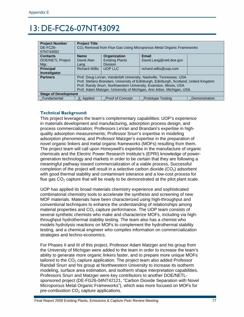
Appendix E
13: DE-FC26-07NT43092 Project Number Project Title DE-FC26-07NT43092
CO2 Removal from Flue Gas Using Microporous Metal Organic Frameworks
Contacts Name Organization Email DOE/NETL Project Mgr.
David Alan Lang
Existing Plants Division
Principal Investigator
Richard Willis UOP LLC [email protected]
Partners Prof. Doug LeVan, Vanderbilt University, Nashville, Tennessee, USA Prof. Stefano Brandani, University of Edinburgh, Edinburgh, Scotland, United Kingdom Prof. Randy Snurr, Northwestern University, Evanston, Illinois, USA Prof. Adam Matzger, University of Michigan, Ann Arbor, Michigan, USA
Stage of Development Fundamental X Applied Proof of Concept Prototype Testing Demonstration Technical Background: This project leverages the team’s complementary capabilities: UOP’s experience in materials development and manufacturing, adsorption process design, and process commercialization; Professors LeVan and Brandani’s expertise in high-quality adsorption measurements; Professor Snurr’s expertise in modeling adsorption phenomena; and Professor Matzger’s expertise in the preparation of novel organic linkers and metal organic frameworks (MOFs) resulting from them. The project team will call upon Honeywell’s expertise in the manufacture of organic chemicals and the Electric Power Research Institute’s (EPRI) knowledge of power-generation technology and markets in order to be certain that they are following a meaningful pathway toward commercialization of a viable process. Successful completion of the project will result in a selective carbon dioxide (CO2) adsorbent with good thermal stability and contaminant tolerance and a low-cost process for flue gas CO2 capture that will be ready to be demonstrated at the pilot plant scale. UOP has applied its broad materials chemistry experience and sophisticated combinatorial chemistry tools to accelerate the synthesis and screening of new MOF materials. Materials have been characterized using high-throughput and conventional techniques to enhance the understanding of relationships among material properties and CO2 capture performance. The UOP team consists of several synthetic chemists who make and characterize MOFs, including via high-throughput hydrothermal stability testing. The team also has a chemist who models hydrolysis reactions on MOFs to complement the hydrothermal stability testing, and a chemical engineer who compiles information on commercialization strategies and techno-economics. For Phases II and III of this project, Professor Adam Matzger and his group from the University of Michigan were added to the team in order to increase the team’s ability to generate more organic linkers faster, and to prepare more unique MOFs tailored to the CO2 capture application. The project team also added Professor Randall Snurr and his group at Northwestern University to increase its isotherm modeling, surface area estimation, and isotherm shape interpretation capabilities. Professors Snurr and Matzger were key contributors to another DOE/NETL-sponsored project (DE-FG26-04NT42121, “Carbon Dioxide Separation with Novel Microporous Metal Organic Frameworks”), which was more focused on MOFs for pre-combustion CO2 capture applications.
Final Report 2009 Existing Plants, Emissions & Capture Peer Review Meeting 77
Appendix E
Increasingly rigorous testing of thermal and contaminant effects are being applied to optimize the MOF materials synthesis and forming process. These studies are being carried out via classical adsorption methods in modern state-of-the-art equipment at Vanderbilt University under the direction of Professor Douglas LeVan. Detailed adsorption measurements on the optimized, scaled-up and formed material under a variety of conditions will drive UOP’s design of a pilot process for analysis of process economics and subsequent pilot testing. Professor Stefano Brandani and his group at the University of Edinburgh round out the adsorption measurements team by applying the zero-length column technique to the analysis of adsorption on MOFs. This methodology enables near-simultaneous evaluation of adsorption capacity and rate on very small samples. Relationship to Program: This project will support important advances within the solid sorbents focus of the CO2 capture and compression area of the NETL EPEC program. The anticipated benefits of the novel MOF materials include an expected increase in CO2 capacity, coupled with ‘tunable’ isotherms for a given set of MOF materials, which should provide multiple compositions for use in CO2 capture technology. Selection also depends upon particular process or cost constraints. Likewise, each MOF material will have a unique and distinct isotherm and isobar shape that could lead to a wide variety of process options for the end user. Additionally, MOF preparation chemistry allows for tunable linker compositions and easy substitution of alternative metal cluster complexes at vertices. This rich variability is anticipated to provide adsorptive plus absorptive mechanisms, which could have a major impact on CO2 selectivity. Primary Project Goal: The primary goal of this project is to develop a low-cost novel sorbent, and a cost-effective process around it, to capture CO2 from coal-based power plant flue gas. Objectives: The key characteristics for a cost-effective process are good sorption properties (selectivity, capacity, kinetics), low energy requirements for regeneration, good thermal and oxidative stability, tolerance to contaminants, and low cost. Metal organic frameworks are microporous, thermally stable materials that have shown exceptional storage capacity for methane, hydrogen, CO2, and other gases. The project team’s technical approach covers all aspects of product development, from narrowing down a broad list of MOFs as potential CO2 sorbent candidates, to evaluation of commercial viability. The project is divided into three distinct, year-long phases:
1. The objective of Phase I was to evaluate known MOFs and enable the down-selection to up to 10 candidate materials for further development based on CO2 capacity and hydrothermal stability. In Phase I, the team prepared more than 50 MOF materials and systematically evaluated their hydrothermal stability at typical and extreme operational conditions. Materials passing hydrothermal stability screening with high CO2 capacity at lower temperatures were then tested for CO2 adsorption capacity at higher, more typical operational temperatures.
2. The objective of Phase II is to further develop and test up to 10 MOF materials and demonstrate one or more MOF materials with improved performance and stability that are suitable for optimization and scale-up in Phase III. In Phase II, the number
Final Report 2009 Existing Plants, Emissions & Capture Peer Review Meeting 78
Appendix E
of candidate materials was reduced to about 10 (based on Phase I results), for which the team has started to measure CO2 capacity in the presence of water at two temperatures. The team is also working to demonstrate the formation of MOFs into commercially viable products that are tolerant to other flue gas contaminants.
3. The objective of Phase III is to demonstrate one or more MOF materials that meet performance targets and have sufficient stability to carry into pilot testing. Phase III performance targets are 15 weight percent (wt%) CO2 capacity at 40°C at up to 1.25 atmospheres pressure. A minimum stability target will be retention of 75% CO2 capacity after exposure of material to up to 15 mol% steam at 150°C for up to 24 hours. In Phase III, at least one optimized product will be prepared at sufficient scale for pilot testing, and its manufacturing cost will be estimated. Detailed performance testing will then be completed on an optimized product, enabling a complete economic analysis and design of a future pilot study.
Final Report 2009 Existing Plants, Emissions & Capture Peer Review Meeting 79
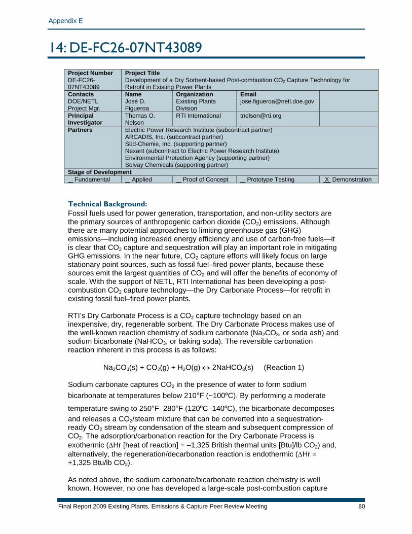
Appendix E
14: DE-FC26-07NT43089 Project Number Project Title DE-FC26-07NT43089
Development of a Dry Sorbent-based Post-combustion CO2 Capture Technology for Retrofit in Existing Power Plants
Contacts Name Organization Email DOE/NETL Project Mgr.
José D. Figueroa
Existing Plants Division
Principal Investigator
Thomas O. Nelson
RTI International [email protected]
Partners Electric Power Research Institute (subcontract partner) ARCADIS, Inc. (subcontract partner) Süd-Chemie, Inc. (supporting partner) Nexant (subcontract to Electric Power Research Institute) Environmental Protection Agency (supporting partner) Solvay Chemicals (supporting partner)
Stage of Development Fundamental Applied Proof of Concept Prototype Testing X Demonstration Technical Background: Fossil fuels used for power generation, transportation, and non-utility sectors are the primary sources of anthropogenic carbon dioxide (CO2) emissions. Although there are many potential approaches to limiting greenhouse gas (GHG) emissions—including increased energy efficiency and use of carbon-free fuels—it is clear that CO2 capture and sequestration will play an important role in mitigating GHG emissions. In the near future, CO2 capture efforts will likely focus on large stationary point sources, such as fossil fuel–fired power plants, because these sources emit the largest quantities of CO2 and will offer the benefits of economy of scale. With the support of NETL, RTI International has been developing a post-combustion CO2 capture technology—the Dry Carbonate Process—for retrofit in existing fossil fuel–fired power plants. RTI’s Dry Carbonate Process is a CO2 capture technology based on an inexpensive, dry, regenerable sorbent. The Dry Carbonate Process makes use of the well-known reaction chemistry of sodium carbonate (Na2CO3, or soda ash) and sodium bicarbonate (NaHCO3, or baking soda). The reversible carbonation reaction inherent in this process is as follows:
Na2CO3(s) + CO2(g) + H2O(g) ↔ 2NaHCO3(s) (Reaction 1)
Sodium carbonate captures CO2 in the presence of water to form sodium bicarbonate at temperatures below 210°F (~100ºC). By performing a moderate
temperature swing to 250°F–280°F (120ºC–140ºC), the bicarbonate decomposes and releases a CO2/steam mixture that can be converted into a sequestration-ready CO2 stream by condensation of the steam and subsequent compression of CO2. The adsorption/carbonation reaction for the Dry Carbonate Process is exothermic (ΔHr [heat of reaction] = –1,325 British thermal units [Btu]/lb CO2) and, alternatively, the regeneration/decarbonation reaction is endothermic (ΔHr = +1,325 Btu/lb CO2). As noted above, the sodium carbonate/bicarbonate reaction chemistry is well known. However, no one has developed a large-scale post-combustion capture
Final Report 2009 Existing Plants, Emissions & Capture Peer Review Meeting 80
Appendix E
technology based on this chemistry because the need or economic motivation has not existed until recently. The key to developing a commercially feasible capture technology based on this chemistry involves parallel process and sorbent development to overcome the challenges of CO2 capture using sodium carbonate, as well as the general challenges of post-combustion CO2 capture. RTI, with NETL’s support, is conducting this process and sorbent development. RTI’s research program has led to novel process designs and sorbent formulations that can be combined into what RTI believes is the most technologically and economically attractive embodiment of the Dry Carbonate Process. RTI’s Dry Carbonate Process is made up of five main process components: an adsorption reactor, a regeneration reactor, a sorbent cooler, a solids transport system, and a gas-solids separation system. In operation, the Dry Carbonate Process takes flue gas from a fossil fuel–fired power plant and removes greater than 90% of the CO2 present in the gas stream. After the flue gas exits the CO2 adsorption reactor, it is emitted to the atmosphere through the plant’s existing stack. CO2-loaded sorbent in the CO2 adsorber exits this reactor and is mechanically conveyed to the regeneration reactor. Within the regenerator, steam is used to indirectly heat the sorbent to the regeneration temperature (~140°C). CO2 and water—the gaseous decomposition products—exit the top of the regenerator and are sent through a condenser to knock out water. The dry CO2 is compressed to required sequestration specifications (or specifications of some other application). The sorbent that exits the regenerator is fully “replenished” (or regenerated) and is mechanically conveyed to the CO2 adsorber, which restarts the CO2 capture/regeneration cycle. Before entering the CO2 adsorber, the sorbent is first cooled to the adsorption temperature (~60°C) using process cooling water. The Dry Carbonate Process is optimally suited for a coal-fired power plant that uses wet, flue gas desulfurization (FGD) technology. The flue gas exiting the wet FGD unit is at a lower temperature and is saturated with water—a reactant in the carbonate reaction, Reaction 1. Although fossil fuel–fired power plants represent initial target applications for the Dry Carbonate Process, this technology can be used in the cement, refining, and gas processing industries with straightforward process modifications. When compared to conventional CO2 capture technologies (i.e., monoethanolamine solvent), RTI’s Dry Carbonate Process exhibits the following advantages:
• Lower total regeneration energy requirement • Lower CO2 removal cost (savings in capital and operating costs and sorbent
make-up costs) • No flue gas pretreatment (no heating, no cooling, no guard beds) • Tolerance to contaminants in flue gas (e.g., oxygen [O2], sulfur dioxide [SO2],
hydrochloric acid [HCl])1 • Readily available and inexpensive sorbent • Non-hazardous and non-toxic sorbent • No hazardous waste generated
1The Dry Carbonate Process is not significantly impacted by contaminant interaction. RTI’s carbonate-based sorbent irreversibly reacts with SO2 and HCl but is not affected by O2, nitrogen oxides, or mercury.
Final Report 2009 Existing Plants, Emissions & Capture Peer Review Meeting 81
Appendix E
Final Report 2009 Existing Plants, Emissions & Capture Peer Review Meeting 82
The specific challenges of CO2 capture using a dry sodium carbonate sorbent are as follows:
• Large solids handling/circulation requirements exist • Exothermic CO2 sorption affects reaction equilibrium • CO2 removal requires an equimolar amount of water • Sodium carbonate reacts irreversibly with SO2 and HCl at flue gas conditions • Raw sodium carbonate is not physically strong • Condensed water causes raw sodium carbonate to agglomerate
Project History Solving the aforementioned challenges has driven RTI’s process and sorbent development efforts. RTI’s efforts started with thermogravimetric analyses to prove the feasibility of the Dry Carbonate Process to remove CO2 and to reliably cycle between sorption and regeneration under realistic flue gas conditions. RTI also conducted thermodynamic simulations of the Dry Carbonate Process to facilitate process development. RTI has evaluated the feasibility and effectiveness of multiple process and sorbent configurations. Fixed-bed reactors, fluidized-bed reactors, dispersed phase gas-solid reactors, supported sorbents, and commercially available bicarbonate materials have all been evaluated. RTI built a bench-scale version of an entrained-bed reactor design that used a supported sorbent to demonstrate continuous CO2 capture and regeneration of RTI’s Dry Carbonate Process. This bench-scale unit allowed RTI to evaluate both process and sorbent design by testing with actual, coal-fired flue gas. The unit that was used consists of two motor-driven screw conveyors and a down-flow, concurrent contactor. The screw conveyors mechanically lift and move the sorbent and are used for indirect heating and cooling. The contactor is essentially a CO2 sorption reactor where solids and flue gas are contacted in a co-current flow. In 2007, RTI’s bench-scale Dry Carbonate Research Unit was moved to the U.S. Environmental Protection Agency (EPA) Multi-Pollutant Control Research Facility in Research Triangle Park, North Carolina. RTI conducted several tests at EPA to prove the effectiveness of RTI’s technology to remove CO2 from coal and natural gas–derived flue gas. Under target process conditions, CO2 capture continuously exceeded 90% from both natural gas and coal-derived flue gas. The average concentrations of CO2 in the natural gas– and coal-derived flue gases were 6 volume percent (vol%) and 10.5 vol%, respectively. Major achievements of EPA testing are as follows:
• Process sustained >90% CO2 capture from both coal and natural gas–derived flue gas
• Testing with actual flue gas showed little difference in CO2 capture performance (compared to simulated flue gas)
• No adverse performance effects were observed due to contaminants • Sorbent proved to be stable and only showed minor signs of physical wear
Specific process and sorbent issues identified include the following:
• Regeneration temperatures of 140°C are ideal for full sorbent regeneration • CO2 capture performance improves with more complete sorbent regeneration • Amount of steam delivered is an important criterion to achieve target
regeneration
Appendix E
Final Report 2009 Existing Plants, Emissions & Capture Peer Review Meeting 83
• Sorbent dynamic CO2 capacity was not sufficient for economical operatechnology
tion of
his project will support important advances within the solid sorbents focus of the n area of the NETL EPEC program.
als, the llowing beneficial outcomes will occur (in addition to these, other benefits are
pture at
n collected; including extended testing with real l
n site.
he primary goal of this project is to deliver a “pre-pilot”-scale demonstration unit—onate Process—and evaluate the long-term reliability of
he specific objectives of RTI’s current project (as detailed in RTI’s statement of ollows:
erational feasibility of bench-scale components based on
m
red by Budget Period 1 des the remaining six
nt project, RTI evaluated multiple potential process configurations for e goal was to select the optimal combination of
• Heat control in CO2 capture reactor is a key to improving CO2 removal performance
Relationship to Program: TCO2 capture and compressio If this project is successful and meets the stated objectives and gofodiscussed in the project objectives section):
1. The Dry Carbonate Process will have demonstrated the ability for CO2 calevels > 90% from real flue gas.
2. Key operating data necessary for more rigorous economic evaluation of the Dry Carbonate Process will have beeflue gas and improved estimates for sorbent makeup due to attrition and chemicadeactivation.
3. The cost-competitive features of the Dry Carbonate Process will have been identified and quantified.
4. Key scale-up issues for commercial deployment will have been identified andaddressed.
5. RTI’s Dry Carbonate Process will be ready for a large-scale demonstration at aactual utility
6. DOE’s technology portfolio for carbon capture will be strengthened. Primary Project Goal: Tbased on RTI’s Dry Carbthis unit to continuously capture >90% of the CO2 in actual coal-fired flue gas. Objectives: Twork) are as f
• Determine optimal process configuration for the Dry Carbonate Process • Demonstrate op
new designs • Demonstrate >90% CO2 removal from actual combustion flue gases • Demonstrate long-term chemical and mechanical stability of sorbent • Demonstrate long-term operational reliability for a large process syste• Demonstrate feasibility of producing sequestration-ready CO2 stream• Update process economic analyses • Develop a technology commercialization plan
(Note: The first two objectives listed above are cove
ctivities of the current project. Budget Period 2 incluaobjectives). Optimal Process Configuration For the currethe Dry Carbonate Process. Thprocess components for process development of a commercial system. The
Appendix E
Final Report 2009 Existing Plants, Emissions & Capture Peer Review Meeting 84
following is a list of some of the designs considered by RTI for the five main process components:
• CO2 adsorber: Duct injection, transport reactor, isothermal fixed- and
dized-bed, fixed fluidized-bed,
generator veyors,
ber,
rations were developed based on these components. The
n tion equipment
ry
al Feasibility of Bench-Scale Components ith this design, RTI began conducting the testing necessary to prepare for the
trol engineering and sizing for a pilot-scale system
O capture improvement in an isothermal environment and to evaluate and ld
ns,
fluidized-bed, vertical down-flow contactor • Sorbent regenerator: Fixed-bed, moving flui
transport reactor, screw conveyors, kiln/furnace • Sorbent cooler: Similar designs as the sorbent re• Solids handling: Belt conveyors, bucket elevators, screw con
pneumatic conveyors • Gas-solid separation: Fabric filter, electrostatic precipitator, water scrub
cyclone
arious process configuVmerits and limitations of these configurations were evaluated based on technical feasibility, ease of integration into a power plant, commercial readiness of process components, anticipated “buy-in” by utility companies, process economics, and the anticipated size of a commercial system. From the results of this evaluation, the most promising design for the Dry Carbonate Process was selected. This design is based on isothermal, moving, fluidized-bed reactors for CO2 adsorption and sorbent regeneration (the full details of this configuration cannot be disclosed due to the proprietary nature of this information). Some of the advantages of this design include the following:
• Isothermal operation decreases sorbent circulation requirements • Less complex process design simplifies process scale-up • Reduces sorbent attrition requirements
acity • Maximizes utilization of sorbent CO2 cap• Increases gas residence time during adsorptio• Reduces complexity of filtration/gas-solid separa
Rm
TI’s new process design focuses on effective heat transfer and heat anagement to meet critical performance and cost targets. Additionally, the new
Dry Carbonate Process design improves the thermodynamic driving force for the capture of CO2 by optimizing contact between the gas and solids. Finally, the chosen design minimizes solids handling requirements and effectively exploits commercially available technologies for moving the quantity of sorbent necessafor the Dry Carbonate Process. RTI believes that this new process design is the most technologically and commercially feasible embodiment of the Dry Carbonate Process. OperationWdesign, construction, and testing of a system capable of removing 1 ton of CO2 per day from coal-fired flue gas. Specific R&D objectives include the following:
• Improving dynamic sorbent capacity for CO2 • Confirming heat-transfer improvements in a bench-scale CO2
reactor/regenerator • Demonstrating solids handling control and gas distribution con• Conducting detailed
A bench-scale isothermal evaluation unit was designed and built to confirm the C 2screen new sorbent materials. This bench-scale reactor has been used to test oand new sorbents using different gas flow rates, temperatures, gas compositio
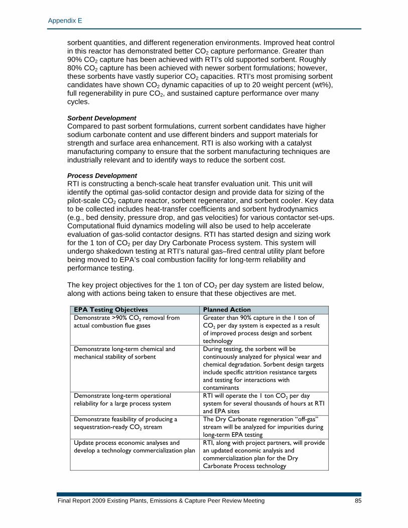
Appendix E
Final Report 2009 Existing Plants, Emissions & Capture Peer Review Meeting 85
sorbent quantities, and different regeneration environments. Improved heat controlin this reactor has demonstrated better CO2 capture performance. Greater than 90% CO2 capture has been achieved with RTI’s old supported sorbent. Roughly 80% CO2 capture has been achieved with newer sorbent formulations; however, these sorbents have vastly superior CO2 capacities. RTI’s most promising sorbencandidates have shown CO2 dynamic capacities of up to 20 weight percent (wt%), full regenerability in pure CO2, and sustained capture performance over many cycles.
t
orbent Development ent formulations, current sorbent candidates have higher
are
rocess Development ench-scale heat transfer evaluation unit. This unit will
he a
ps.
work
e
he key project objectives for the 1 ton of CO2 per day system are listed below,
SCompared to past sorbsodium carbonate content and use different binders and support materials for strength and surface area enhancement. RTI is also working with a catalyst manufacturing company to ensure that the sorbent manufacturing techniquesindustrially relevant and to identify ways to reduce the sorbent cost. PRTI is constructing a bidentify the optimal gas-solid contactor design and provide data for sizing of tpilot-scale CO2 capture reactor, sorbent regenerator, and sorbent cooler. Key datto be collected includes heat-transfer coefficients and sorbent hydrodynamics (e.g., bed density, pressure drop, and gas velocities) for various contactor set-uComputational fluid dynamics modeling will also be used to help accelerate evaluation of gas-solid contactor designs. RTI has started design and sizing for the 1 ton of CO2 per day Dry Carbonate Process system. This system will undergo shakedown testing at RTI’s natural gas–fired central utility plant beforbeing moved to EPA’s coal combustion facility for long-term reliability and performance testing. Talong with actions being taken to ensure that these objectives are met.
EPA Testing Objectives Planned Action Demonstrate >90% CO2 removal from apture in the 1 ton of
actual combustion flue gases Greater than 90% cCO2 per day system is expected as a resultof improved process design and sorbent technology
Demonstrate long-term chemical and g, the sorbent will be ear and mechanical stability of sorbent
During testincontinuously analyzed for physical wchemical degradation. Sorbent design targets include specific attrition resistance targets and testing for interactions with contaminants
Demonstrate long-term operational e the 1 ton CO2 per day RTI reliability for a large process system
RTI will operatsystem for several thousands of hours atand EPA sites
Demonstrate feasibility of producing a nate regeneration “ofsequestration-ready CO2 stream
The Dry Carbo f-gas” stream will be analyzed for impurities during
long-term EPA testing Update process economic analyses and
plan ners, will provide
develop a technology commercialization
RTI, along with project partan updated economic analysis and commercialization plan for the DryCarbonate Process technology

Appendix E
With a strong focus on commercialization of this technology, RTI is already actively planning future activities. For example, RTI has been in communication with the utility plant for a local university to conduct slipstream tests of the Dry Carbonate Process. The initial goal was for this utility to host the long-term testing of the 1 ton CO2 per day unit to accumulate operating experience with a real utility. However, this may also provide the opportunity to accumulate actual flue gas testing more effectively than at EPA’s facilities (which is a research facility). Furthermore, this utility is already expressing interest in hosting a larger unit. RTI is also working to find additional potential host sites. To facilitate these discussions, RTI has begun to develop preliminary design specification for a larger unit that would process a flue gas stream required for producing about 5 megawatts of electricity. Although the current project focuses on developing this technology for retrofitting existing coal-fired power plants, RTI is already working to find future host sites for the 1 ton CO2 per day unit (or copies) at non-utility host sites that might benefit from the Dry Carbonate Process for CO2 capture, such as cement kilns and refineries using catalytic cracking to upgrade lower-value feedstocks.
Final Report 2009 Existing Plants, Emissions & Capture Peer Review Meeting 86
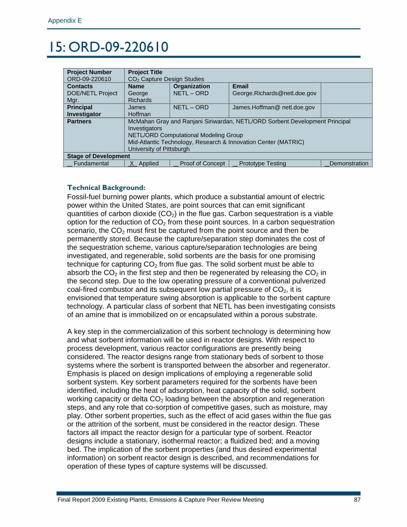
Appendix E
15: ORD-09-220610 Project Number Project Title ORD-09-220610 CO2 Capture Design Studies Contacts Name Organization Email DOE/NETL Project Mgr.
George Richards
NETL – ORD [email protected]
Principal Investigator
James Hoffman
NETL – ORD James.Hoffman@ netl.doe.gov
Partners McMahan Gray and Ranjani Siriwardan, NETL/ORD Sorbent Development Principal Investigators NETL/ORD Computational Modeling Group Mid-Atlantic Technology, Research & Innovation Center (MATRIC) University of Pittsburgh
Stage of Development Fundamental X Applied Proof of Concept Prototype Testing Demonstration Technical Background: Fossil-fuel burning power plants, which produce a substantial amount of electric power within the United States, are point sources that can emit significant quantities of carbon dioxide (CO2) in the flue gas. Carbon sequestration is a viable option for the reduction of CO2 from these point sources. In a carbon sequestration scenario, the CO2 must first be captured from the point source and then be permanently stored. Because the capture/separation step dominates the cost of the sequestration scheme, various capture/separation technologies are being investigated, and regenerable, solid sorbents are the basis for one promising technique for capturing CO2 from flue gas. The solid sorbent must be able to absorb the CO2 in the first step and then be regenerated by releasing the CO2 in the second step. Due to the low operating pressure of a conventional pulverized coal-fired combustor and its subsequent low partial pressure of CO2, it is envisioned that temperature swing absorption is applicable to the sorbent capture technology. A particular class of sorbent that NETL has been investigating consists of an amine that is immobilized on or encapsulated within a porous substrate. A key step in the commercialization of this sorbent technology is determining how and what sorbent information will be used in reactor designs. With respect to process development, various reactor configurations are presently being considered. The reactor designs range from stationary beds of sorbent to those systems where the sorbent is transported between the absorber and regenerator. Emphasis is placed on design implications of employing a regenerable solid sorbent system. Key sorbent parameters required for the sorbents have been identified, including the heat of adsorption, heat capacity of the solid, sorbent working capacity or delta CO2 loading between the absorption and regeneration steps, and any role that co-sorption of competitive gases, such as moisture, may play. Other sorbent properties, such as the effect of acid gases within the flue gas or the attrition of the sorbent, must be considered in the reactor design. These factors all impact the reactor design for a particular type of sorbent. Reactor designs include a stationary, isothermal reactor; a fluidized bed; and a moving bed. The implication of the sorbent properties (and thus desired experimental information) on sorbent reactor design is described, and recommendations for operation of these types of capture systems will be discussed.
Final Report 2009 Existing Plants, Emissions & Capture Peer Review Meeting 87
Appendix E
Relationship to Program: This project will support important advances within the solid sorbents focus of the CO2 capture and compression area of the NETL EPEC program. Carbon capture and sequestration holds the promise of continued fossil fuel usage while addressing global climate change concerns. The separation/capture step is the dominant cost in a CO2 mitigation strategy of carbon capture and sequestration. Existing wet scrubbing is energy intensive with respect to regeneration heat duty, and dry sorbent scrubbing holds the potential to lower the regeneration heat duty. Once a sorbent-based dry scrubbing process is fully investigated and any uncertainty is resolved, the technology will provide a CO2 capture technique that is applicable to the existing fleet as well as to new coal-fired power generators. Thus, a CO2 removal process will be available to the electric power industry that addresses capturing CO2 for eventual storage. Primary Project Goal: The primary goal of this project is to provide engineering support and reactor design oversight for the development of CO2 removal processes utilizing solid sorbents for flue gas application currently under development by NETL in-house researchers. The activities support the overall DOE CO2 program goal of limiting the increase in cost of energy service for CO2 capture and sequestration from large point sources. Objectives: Office of Research and Development researchers are seeking to develop solid, durable, regenerable sorbents that have a high selectivity and high adsorption capacity for CO2 at conditions suitable for post-combustion capture. The primary objective of this project is to ensure that engineering and reactor design issues are addressed in the sorbent development toward commercialization. The synergistic efforts are intended to ultimately meet the programmatic goal for energy conversion systems that can remove 90% CO2 while keeping the increase in cost of energy service below 35%.
Final Report 2009 Existing Plants, Emissions & Capture Peer Review Meeting 88
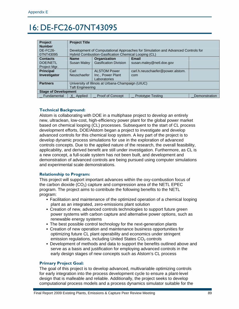
Appendix E
16: DE-FC26-07NT43095 Project Number
Project Title
DE-FC26-07NT43095
Development of Computational Approaches for Simulation and Advanced Controls for Hybrid Combustion-Gasification Chemical Looping (CL)
Contacts Name Organization Email DOE/NETL Project Mgr.
Susan Maley Gasification Division [email protected]
Principal Investigator
Carl Neuschaefer
ALSTOM Power Inc., Power Plant Laboratories
Partners University of Illinois at Urbana-Champaign (UIUC) Taft Engineering
Stage of Development Fundamental X Applied Proof of Concept Prototype Testing Demonstration Technical Background: Alstom is collaborating with DOE in a multiphase project to develop an entirely new, ultraclean, low-cost, high-efficiency power plant for the global power market based on chemical looping (CL) processes. Subsequent to the start of CL process development efforts, DOE/Alstom began a project to investigate and develop advanced controls for this chemical loop system. A key part of the project is to develop dynamic process simulations for use in the exploration of advanced controls concepts. Due to the applied nature of the research, the overall feasibility, applicability, and derived benefit are still under investigation. Furthermore, as CL is a new concept, a full-scale system has not been built, and development and demonstration of advanced controls are being pursued using computer simulations and experimental scale demonstrations. Relationship to Program: This project will support important advances within the oxy-combustion focus of the carbon dioxide (CO2) capture and compression area of the NETL EPEC program. The project aims to contribute the following benefits to the NETL program:
• Facilitation and maintenance of the optimized operation of a chemical looping plant as an integrated, zero-emissions plant solution
• Creation of new, advanced controls technologies to support future green power systems with carbon capture and alternative power options, such as renewable energy systems
• The best possible control technology for the next-generation plants • Creation of new operation and maintenance business opportunities for
optimizing future CL plant operability and economics under stringent emission regulations, including United States CO2 controls
• Development of methods and data to support the benefits outlined above and serve as a basis and justification for employing advanced controls in the early design stages of new concepts such as Alstom’s CL process
Primary Project Goal: The goal of this project is to develop advanced, multivariable optimizing controls for early integration into the process development cycle to ensure a plant-level design that is malleable and reliable. Additionally, the project seeks to develop computational process models and a process dynamics simulator suitable for the
Final Report 2009 Existing Plants, Emissions & Capture Peer Review Meeting 89

Appendix E
Final Report 2009 Existing Plants, Emissions & Capture Peer Review Meeting 90
investigation and development of advanced sensing and control systems for advanced power generation based on chemical looping in coal-fired systems. Objectives: The main objectives of this project are divided into the following subtasks:
1. Build simplified, proof-of-concept CL process simulation models with dynamic capability suitable to evaluate control methods and concepts
2. Investigate sensors and advanced (multivariable/model-based) process controls and analysis methods
3. Develop a design concept for an advanced process control system as a starting point for design and implementation of the controls in preparation for a chemical looping prototype-scale facility project
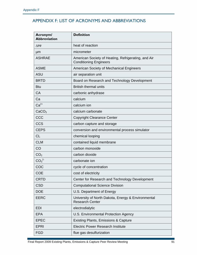
Appendix F
APPENDIX F: LIST OF ACRONYMS AND ABBREVIATIONS
Acronym/ Abbreviation
Definition
ΔHr heat of reaction
µm micrometer
ASHRAE American Society of Heating, Refrigerating, and Air Conditioning Engineers
ASME American Society of Mechanical Engineers
ASU air separation unit
BRTD Board on Research and Technology Development
Btu British thermal units
CA carbonic anhydrase
Ca calcium
Ca2+ calcium ion
CaCO3 calcium carbonate
CCC Copyright Clearance Center
CCS carbon capture and storage
CEPS conversion and environmental process simulator
CL chemical looping
CLM contained liquid membrane
CO carbon monoxide
CO2 carbon dioxide
CO32- carbonate ion
COC cycle of concentration
COE cost of electricity
CRTD Center for Research and Technology Development
CSD Computational Science Division
DOE U.S. Department of Energy
EERC University of North Dakota, Energy & Environmental Research Center
EDI electrodialytic
EPA U.S. Environmental Protection Agency
EPEC Existing Plants, Emissions & Capture
EPRI Electric Power Research Institute
FGD flue gas desulfurization
Final Report 2009 Existing Plants, Emissions & Capture Peer Review Meeting 91
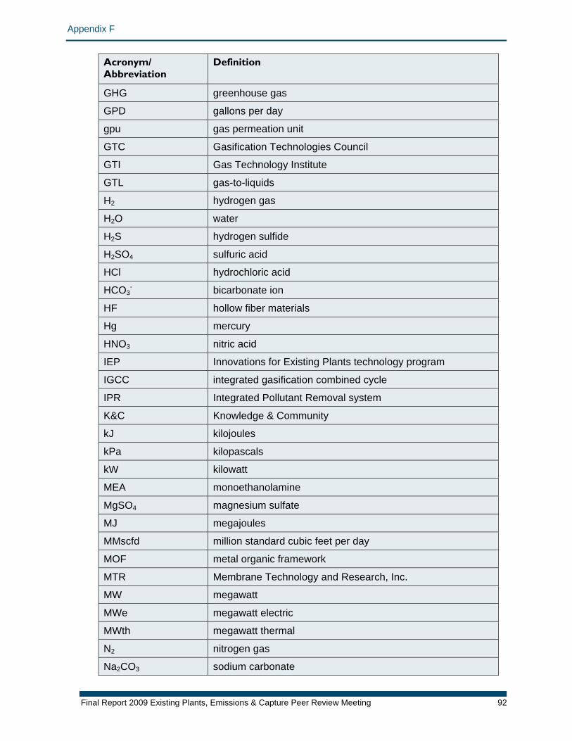
Appendix F
Final Report 2009 Existing Plants, Emissions & Capture Peer Review Meeting 92
Acronym/ Abbreviation
Definition
GHG greenhouse gas
GPD gallons per day
gpu gas permeation unit
GTC Gasification Technologies Council
GTI Gas Technology Institute
GTL gas-to-liquids
H2 hydrogen gas
H2O water
H2S hydrogen sulfide
H2SO4 sulfuric acid
HCl hydrochloric acid
HCO3- bicarbonate ion
HF hollow fiber materials
Hg mercury
HNO3 nitric acid
IEP Innovations for Existing Plants technology program
IGCC integrated gasification combined cycle
IPR Integrated Pollutant Removal system
K&C Knowledge & Community
kJ kilojoules
kPa kilopascals
kW kilowatt
MEA monoethanolamine
MgSO4 magnesium sulfate
MJ megajoules
MMscfd million standard cubic feet per day
MOF metal organic framework
MTR Membrane Technology and Research, Inc.
MW megawatt
MWe megawatt electric
MWth megawatt thermal
N2 nitrogen gas
Na2CO3 sodium carbonate
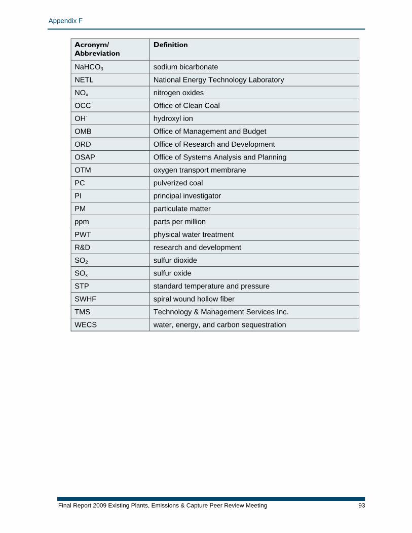
Appendix F
Final Report 2009 Existing Plants, Emissions & Capture Peer Review Meeting 93
Acronym/ Abbreviation
Definition
NaHCO3 sodium bicarbonate
NETL National Energy Technology Laboratory
NOx nitrogen oxides
OCC Office of Clean Coal
OH- hydroxyl ion
OMB Office of Management and Budget
ORD Office of Research and Development
OSAP Office of Systems Analysis and Planning
OTM oxygen transport membrane
PC pulverized coal
PI principal investigator
PM particulate matter
ppm parts per million
PWT physical water treatment
R&D research and development
SO2 sulfur dioxide
SOx sulfur oxide
STP standard temperature and pressure
SWHF spiral wound hollow fiber
TMS Technology & Management Services Inc.
WECS water, energy, and carbon sequestration