Embed Size (px)
Citation preview
U.S. Department of Justice Office of Justice Programs National Institute of Justice
National Institute of Justice
Mobile Antennas
NI J S tandard-0205.02
ABOUT THE LAW ENFORCEMENT AND CORRECTIONS STANDARDS AND TESTING PROGRAM
The Law Enforcement and Corrections Standards and Testing Program is sponsored by the Office of Science and Technology of the National Institute of Justice (NIJ), U.S. Department of Justice. The program responds to the mandate of the Justice System Improvement Act of 1979, which created NIJ and directed it to encourage research and develop- ment to improve the criminal justice system and to disseminate the results to Federal, State, and local agencies.
The Law Enforcement and Corrections Standards and Testing Program is an applied research effort that determines the technological needs of justice system agencies, sets minimum performance standards for specific devices, tests commercially available equipment against those standards, and disseminates the standards and the test results to criminal justice agencies nationwide and internationally.
The program operates through: The Law Enforcement and Corrections Technology Advisory Council (LECTAC) consisting of nationally recog-
nized criminal justice practitioners from Federal, State, and local agencies, which assesses technological needs and sets priorities for research programs and items to be evaluated and tested.
The Office of Law Enforcement Standards (OLES) at the National Institute of Standards and Technology, which develops voluntary national performance standards for compliance testing to ensure that individual items of equipment are suitable for use by criminal justice agencies. The standards are based upon laboratory testing and evaluation of representative samples of each item of equipment to determine the key attributes, develop test methods, and establish minimum performance requirements for each essential attribute. In addition to the highly technical standards, OLES also produces technical reports and user guidelines that explain in nontechnical terms the capabilities of available equipment.
The National Law Enforcement and Corrections Technology Center (NLECTC), operated by a grantee, which supervises a national compliance testing program conducted by independent agencies. The standards developed by OLES serve as performance benchmarks against which commercial equipment is measured. The facilities, personnel, and testing capabilities of the independent laboratories are evaluated by OLES prior to testing each item of equipment, and OLES helps the Technology Center staff review and analyze data. Test results are published in Consumer Product Reports designed to help justice system procurement officials make informed purchasing decisions.
Publications issued by the National Institute of Justice, including those of the Law Enforcement and Corrections Standards and Testing Program, are available from the National Criminal Justice Reference Service (NCJRS), which serves as a central information and reference source for the Nation's criminal justice community. For further informa- tion, or to register with NCJRS, write to the National Institute of Justice, National Criminal Justice Reference Service, Washington, DC 2053 1.
I The National Institute of Justice is a component of the Office of I I Justice Programs, which also includes the Bureau of Justice Assis-
tance, Bureau of Justice Statistics, Office of Juvenile Justice and I
U.S. Department of Justice Office of Justice Programs National Institute of Justice
Mobile Antennas NIJ Standard-0205.02 Supersedes NIJ-STD-0205.01 dated May 1989
October 1997
National Institute of Justice
Jeremy Travis Director
The technical effort to develop this standard was conducted under Interagency Agreement No. 94-IJ-R-004,
Project No. 96-007.
This standard was formulated by the Office of Law Enforcement Standards (OLES) of the
National Institute of Standards and Technology (NIST) under the direction of A. George Lieberman,
Program Manager for Communications Systems, and Kathleen M. Higgins, Director of OLES.
Revision of this standard was performed at the National Telecommunications and Information Administration,
Institute for Telecommunications Sciences by John M. Vanderau.
The preparation of this standard was sponsored by the National Institute of Justice, David G. Boyd,
Director, Office of Science and Technology.
FOREWORD
This document, NIJ Standard-0205.02, Mobile Antennas, is an equipment standard developed by the Office of Law Enforcement Standards of the National Institute of Standards and Technology. It is produced as part of the Law Enforcement and Corrections Standards and Testing Program of the National Institute of Justice. A brief description of the program appears on the inside front cover.
This standard is a technical document that specifies performance and other requirements equipment should meet to satisfy the needs of criminal justice agencies for high quality service. Purchasers can use the test methods described in this standard to determine whether a particular piece of equipment meets the essential requirements, or they may have the tests conducted on their behalf by a qualified testing laboratory. Procurement officials may also refer to this standard in their purchasing documents and require that equipment offered for purchase meet the requirements. Compliance with the requirements of the standard may be attested to by an independent laboratory or guaranteed by the vendor.
Because this NIJ standard is designed as a procurement aid, it is necessarily highly technical. For those who seek general guidance concerning the selection and application of law enforcement equipment, user guides have also been published. The guides explain in nontechnical language how to select equipment capable of the performance required by an agency.
NU standards are subjected to continuing review. Technical comments and recommended revisions are welcome. Please send suggestions to the Director, Office of Science and Technology, National Institute of Justice, U.S. Department of Justice, Washington, DC 2053 1.
Before citing this or any other NIJ standard in a contract document, users should verify that the most recent edition of the standard is used. Write to: Director, Office of Law Enforcement Standards, National Institute of Standards and Technology, Gaithersburg, MD 20899.
David G. Boyd, Director Office of Science and Technology National Institute of Justice
NIJ STANDARD FOR
MOBILE ANTENNAS
CONTENTS
........................................................................... FOREWORD .............................................................................. 1 . PURPOSE AND SCOPE
..................................................................................... 2 . CLASSIFICATION .......................................................................................... 3 . DEFINITIONS
..................................................................................... 4 . REQUIREMENTS .......................................................................... 4.1 Minimum Performance ................................................................................ 4.2 User Information ................................................................................... 4.3 Environmental ........................................................................... 4.4 Antenna Power Rating ........................................................................... 4.5 Relative Antenna Gain ................................................................................ 4.6 Radiation Pattern .................................................................... 4.7 Voltage Standing Wave Ratio ................................................................................. 4.8 Radiation Hazard ...................................................................................... . 5 TEST METHODS ......................................................................... 5.1 Standard Test Conditions .................................................................................. 5.2 Instrumentation ............................................................................ 5.3 Rf Performance Tests
..................................................................... 5.4 Environmental Test Methods ................................................................................ 5.5 Radiation Hazard ............................................................................ APPENDIX A-REFERENCES
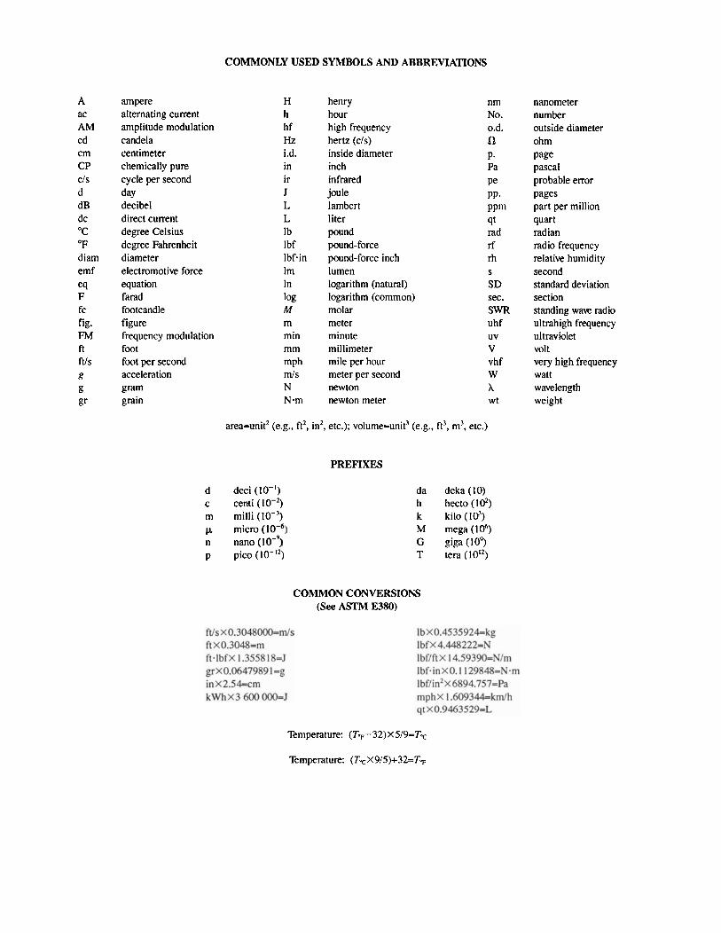
COMMONLY USED SYMBOLS AND ABBREVIATIONS
A ac AM cd cm CP CIS d dB dc OC "F diam emf eq F fc fig. FM ft ft/s g g gr
ampere alternating current amplitude modulation candela centimeter chemically pure cycle per second day decibel direct current degree Celsius degree Fahrenheit diameter electromotive force equation farad footcandle figure frequency modulation foot foot per second acceleration gram grain
H h h f Hz i.d. in ir J L L Ib Ibf Ibfmin Im In log M m min mm mph I d s N N.m
henry hour high frequency hertz (cis) inside diameter inch infrared joule lambert liter pound pound-force pound-force inch lumen logarithm (natural) logarithm (common) molar meter minute millimeter mile per hour meter per second newton newton meter
nm No. 0.d. n P- Pa Pe PP. PPm qt rad rf m S
SD sec. SWR uhf uv v vhf W A wt
area=unit2 (e.g., ft2, in2, etc.); volume=unit3 (e.g., ft3, m3, etc.)
d deci (lo-') c centi (lo-*) m milli (lo-')
micro n nano p pic0 (lo-")
PREFIXES
da deka (10) h hecto ( I d ) k kilo ( I d ) M mega ( I d ) G giga (109 T tera (10'')
COMMON CONVERSIONS (See ASTM E380)
nanometer number outside diameter ohm page pascal probable error pages part per million quart radian radio frequency relative humidity second standard deviation section standing wave radio ultrahigh frequency ultraviolet volt very high frequency watt wavelength weight
Temperature: (TT-32)x5/9=TT
Temperature: (TTX9/5)+32=T~
NIJ Standard-0205.02
NIJ STANDARD FOR
MOBILE ANTENNAS
1. PURPOSE AND SCOPE
The purpose of this document is to establish minimum performance requirements and methods of test for antennas that are mounted on police vehicles or other mobile platforms used by law enforcement agencies. Whereas the antennas under test must meet all the rf electrical performance specifications cited in this document at ambient conditions, the environmental performance specifications stated herein should be selectively applied according to the anticipated operating environment of the antenna. That is, the antenna need only comply with those environmental specifications not waived by the procuring agency. This standard is a revision of NIJ Standard-0205.01, dated May 1989. This revision incorporates the latest recommended methods and procedures of industry standards related to communications antennas and environmental test procedures.
2. CLASSIFICATION
2.1 Operating Frequency
2.1.1 Type l
Antennas for use in the 25 MHz to 50 MHz band.
2.1.2 Type ll
Antennas for use in the 150 MHz to 174 MHz band.
2.1.3 Type Ill
Antennas for use in the 406 MHz to 512 MHz band.
2.1.4 Type lV
Antennas for use in the 806 MHz to 930 MHz band.
2.2 Directional Pattern
2.2.1 Omnidirectional Antennas
2.2.2 Directional Antennas
3. DEFINITIONS
The principal terms used in this document are defined in this section. These terms comply with accepted industry definitions specified in ANSIIIEEE STD 145-1993, IEEE Standard Definitions of Terms for Antennas. Other terms are defined within this section and EIAITIA-329B-1, Minimum Standards for Communications Antennas, Part 11- Vehicular Antennas.
3.1 Ambient Conditions
Ambient conditions of temperature and humidity are defined as any combination of prevailing weather conditions of temperature between 13" to 35 "C (55" to 95 "F) and relative humidity between 25 to 85 percent.
3.2 'Antenna Power Rating
The maximum continuous-wave power that can be continuously applied to an antenna without degrading its perfor- mance.
3.3 Dipole Antenna, Resonant Half-Wavelength
A straight metallic radiator, usually energized at its center, whose length is slightly less than one-half wavelength' of the energizing signal and whose diameter is small compared to its length. The current goes to zero at the ends of the antenna. The maximum radiation intensity lies in a plane normal to the axis of the antenna.
3.4 Effective Antenna Volume
The effective antenna volume is the actual volume occupied by the radiating part of the antenna plus one-half wavelength all the way around, taking into account all appropriate conditions of the antenna under test. In certain applications, the supporting structure is in the rf field and shall be included in the effective antenna volume.
3.5 Isotropic Radiator
A hypothetical antenna that radiates or receives equally in all directions.
3.6 Major Lobe (Main Lobe)
The radiation lobe that contains the direction of maximum radiation.
3.7 Pattern Recorder
A device that records the amplitude of the output signal from an antenna and receiver and displays the amplitude as a function of the spatial orientation of the antenna. This device may collect and store tabular data or graphics informa- tion originating from a network analyzer or similar rf measurement device, and be capable of graphically plotting or displaying measured data or presenting the data in tabular format.
3.8 Polarization
In a given direction from the antenna, the orientation of the electric field vector of the wave radiated from the antenna, or the orientation of the electric field vector of the wave incident upon the antenna that produces the maximum voltage at the antenna terminals.
3.9 Quiet Zone
That region of an antenna test range illuminated by an electromagnetic wave from the source antenna where the amplitude taper (ripple) is less than 0.25 dB and phase taper (ripple) is less than 22.5". The quiet zone must totally enclose the effective antenna volume of the antenna under test.
' Dipole antennas in free space which are exactly one-half wavelength long exhibit an impedance which has an inductive component and is repre- sented by a complex number73+j42.5 0, the imaginary pan of the complex number indicates the inductive effects. 'lhe reactance of the antenna depends on the length and diamet,er,(in wavelengths) of the antenna in a complicated fashion involving sine integral functions and cosine integral functions. By shortening the antenna slightly, the inductive component can be made equal to zero. When there is no inductive or capacitive component of impedance, then the antenna is said to be resonant. Shortening the antenna from one-half wavelength to bring it into resonance also lowers the radiation resistance from 73 0 to a value closer to 50 R; this further improves the impedance match and VSWR between the antenna and the 50 R coaxial cable transmission line.
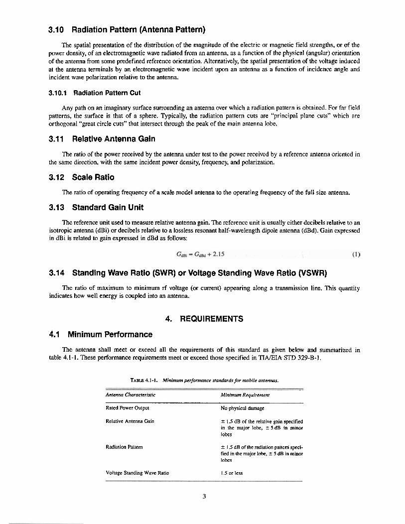
3.10 Radiation Pattern (Antenna Pattern)
The spatial presentation of the distribution of the magnitude of the electric or magnetic field strengths, or of the power density, of an electromagnetic wave radiated from an antenna, as a function of the physical (angular) orientation of the antenna from some predefined reference orientation. Alternatively, the spatial presentation of the voltage induced at the antenna terminals by an electromagnetic wave incident upon an antenna as a function of incidehce angle and incident wave polarization relative to the antenna.
3.10.1 Radiation Pattern Cut
Any path on an imaginary surface surrounding an antenna over which a radiation pattern is obtained. For far field patterns, the surface is that of a sphere. Typically, the radiation pattern cuts are "principal plane cuts" which are orthogonal "great circle cuts" that intersect through the peak of the main antenna lobe.
3.1 1 Relative Antenna Gain
The ratio of the power received by the antenna under test to the power received by a reference antenna oriented in the same direction, with the same incident power density, frequency, and polarization.
3.12 Scale Ratio
The ratio of operating frequency of a scale model antenna to the operating frequency of the full size antenna.
3.13 Standard Gain Unit
The reference unit used to measure relative antenna gain. The reference unit is usually either decibels relative to an isotropic antenna (dBi) or decibels relative to a lossless resonant half-wavelength dipole antenna (dBd). Gain expressed in dBi is related to gain expressed in dBd as follows:
3.14 Standing Wave Ratio (SWR) or Voltage Standing Wave Ratio (VSWR)
The ratio of maximum to minimum rf voltage (or current) appearing along a transmission line. This quantity indicates how well energy is coupled into an antenna.
4. REQUIREMENTS
4.1 Minimum Performance
The antenna shall meet or exceed all the requirements of this standard as given below and summarized in table 4.1-1. These performance requirements meet or exceed those specified in TINEIA STD 329-B.1.
TABLE 4.1 - 1. Minimum performance standardsfor mobile anrennas.
Antenna Characteristic ~ -~ ~ ~ -
Minimum Requirement
Rated Power Output No physical damage
Relative Antenna Gain
Radiation Pattern
2 1.5 dB of the relative gain specified in the major lobe, 2 S dB in minor lobes
+. 1.5 dB of the radiation patterri speci- fied in the major lobe, Z 5 dB in minor lobes
Voltage Standing Wave Ratio 1.5 or less
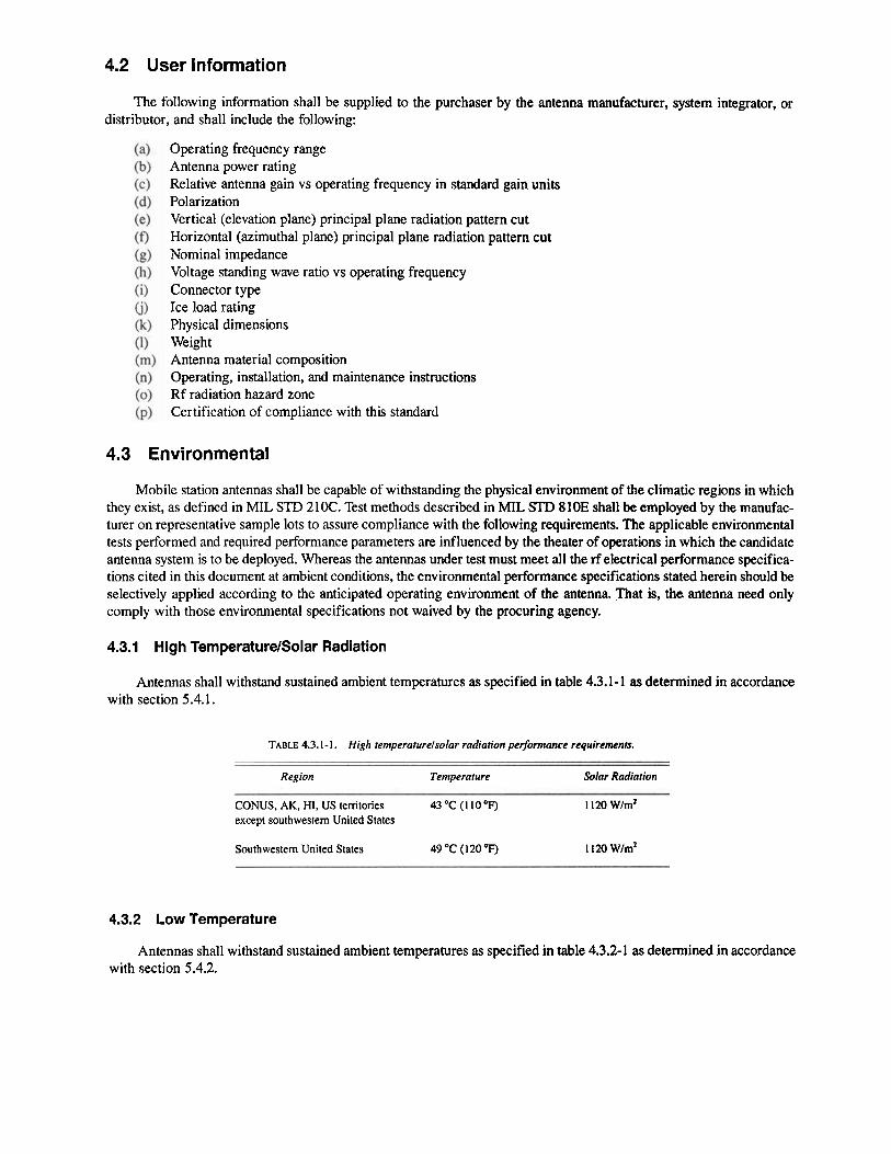
4.2 User Information
The following information shall be supplied to the purchaser by the antenna manufacturer, system integrator, or distributor, and shall include the following:
Operating frequency range Antenna power rating Relative antenna gain vs operating frequency in standard gain units Polarization Vertical (elevation plane) principal plane radiation pattern cut Horizontal (azimuthal plane) principal plane radiatiod pattern cut Nominal impedance Voltage standing wave ratio vs operating frequency Connector type Ice load rating Physical dimensions Weight Antenna material composition Operating, installation, and maintenance instructions Rf radiation hazard zone Certification of compliance with this standard
4.3 Environmental
Mobile station antennas shall be capable of withstanding the physical environment of the climatic regions in which they exist, as defined in MIL STD 210C. Test methods described in M E S D 810E shall be employed by the manufac- turer on representative sample lots to assure compliance with the following requirements. The applicable environmental tests performed and required performance parameters are influenced by the theater of operations in which the candidate antenna system is to be deployed. Whereas the antennas under test must meet all the rf electrical performance specifica- tions cited in this document at ambient conditions, the environmental performance specifications stated herein should be selectively applied according to the anticipated operating environment of the antenna. That is, the antenna need only comply with those environmental specifications not waived by the procuring agency.
4.3.1 High TemperaturelSolar Radiation
Antennas shall withstand sustained ambient temperatures as specified in table 4.3.1-1 as determined in accordance with section 5.4.1.
TABLE 4.3.1 - 1. High temperatwelsolar radiation performance requirements.
Region Temperature Solar Radiation
CONUS, AK, HI, US territories 43OC (11OOF) 1 120 w/m2 except southwestern United States
Southwestern United States 49 "C (120 OF) 1 120 wlm2
4.3.2 Low Temperature
Antennas shall withstand sustained ambient temperatures as specified in table 4.3.2-1 as determined in accordance with section 5.4.2.
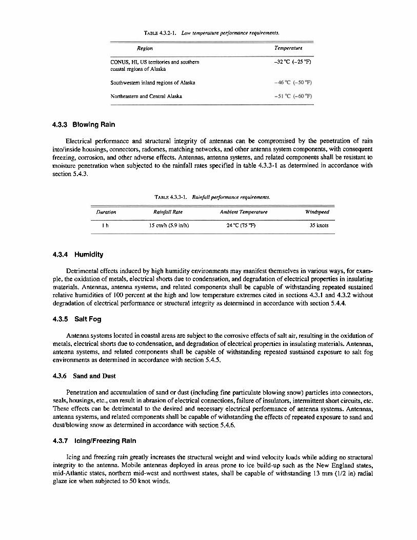
TABLE 4.3.2-1. Low temperature performance requirements.
Region Temperature
CONUS, HI, US territories and southern coastal regions of Alaska
-32 OC (-25 OF)
Southwestern inland regions of Alaska -46°C (-5OOF)
Northeastern and Central Alaska -51 OC (-60°F)
4.3.3 Blowing Rain
Electrical performance and structural integrity of antennas can be compromised by the penetration of rain intolinside housings, connectors, radomes, matching networks, and other antenna system components, with consequent freezing, corrosion, and other adverse effects. Antennas, antenna systems, and related components shall be resistant to moisture penetration when subjected to the rainfall rates specified in table 4.3.3-1 as determined in accordance with section 5.4.3.
TABLE 4.3.3- 1. Rainfall performance requirements.
Duration Rainfall Rate Ambient Temperature Windspeed
I h 15 cmlh (5.9 inlh) 24 OC (75 OF) 35 knots
4.3.4 Humidity
Detrimental effects induced by high humidity environments may manifest themselves in various ways, for exam- ple, the oxidation of metals, electrical shorts due to condensation, and degradation of electrical properties in insulating materials. Antennas, antenna systems, and related components shall be capable of withstanding repeated sustained relative humidities of 100 percent at the high and low temperature extremes cited in sections 4.3.1 and 4.3.2 without degradation of electrical performance or structural integrity as determined in accordance with section 5.4.4.
4.3.5 Salt Fog
Antenna systems located in coastal areas are subject to the corrosive effects of salt air, resulting in the oxidation of metals, electrical shorts due to condensation, and degradation of electrical properties in insulating materials. Antennas, antenna systems, and related components shall be capable of withstanding repeated sustained exposure to salt fog environments as determined in accordance with section 5.4.5.
4.3.6 Sand and Dust
Penetration and accumulation of sand or dust (including fine particulate blowing snow) particles into connectors, seals, housings, etc., can result in abrasion of electrical connections, failure of insulators, intermittent short circuits, etc. These effects can be detrimental to the desired and necessary electrical performance of antenna systems. Antennas, antenna systems, and related components shall be capable of withstanding the effects of repeated exposure to sand and dustlblowing snow as determined in accordance with section 5.4.6.
4.3.7 IcinglFreezing Rain
Icing and freezing rain greatly increases the structural weight and wind velocity loads while adding no structural integrity to the antenna. Mobile antemas deployed in areas prone to ice build-up such as the New England states, mid-Atlantic states, northern mid-west and northwest states, shall be capable of withstanding 13 mm (112 in) radial glaze ice when subjected to 50 knot winds.
4.4 Antenna Power Rating
The antenna shall meet the requirements of sections 4.5 through 4.7 immediately after being subjected to the test described in section 5.4. The antenna shall not be physically damaged by this test.
4.5 Relative Antenna Gain
The relative antenna gain, measured in accordance with section 5.5, shall be within + 1.5 dB of the relative gain specified by the manufacturer in accordance with section 4.2.c.
4.6 Radiation Pattern
4.6.1 Vertical (Elevation Plane) Pattern
The vertical radiation pattern, measured in accordance with section 5.6.1, shall be within 2 1.5 dB of the vertical (elevation plane) radiation pattern specified by the manufacturer in accordance with section 4.2.e.
4.6.2 Horizontal (Azimuthal Plane) Pattern
The horizontal radiation pattern, measured in accordance with section 5.6.2, shall be within -C 1.5 dB of the horizontal (azimuthal plane) radiation pattern specified by the manufacturer in accordance with section 4.2.f. For omnidirectional antennas, the horizontal radiation pattern shall be within + 1.5 dB throughout a 360" range in azimuth.
4.7 Voltage Standing Wave Ratio
The VSWR of the antenna, measured in accordance with section 5.7, shall be 1.5 or less, referenced to a 50 il system.
4.8 Radiation Hazard
Radiation hazard zones shall be identified by measurements performed in conformance with the provisions of ANSYIEEE C95.3-1991. Radiation hazard zones are those volumes of space surrounding the antenna where the electro- magnetic power density and/or field strengths exceed the industry recognized limits of ANSYIEEE C95.1-1991. The radiation hazard zone shall be determined when transmitting at the antenna's fully rated power output. For single radiating frequencies, permissible limits of exposure are 1 mW/cm2 for type U antennas and ranging from about 1.4 mW/cm2 to about 3.5 mW/cm2 for type III and type IV antennas. For type I antennas, permissible limits of exposure are expressed in field strength rather than power density, and range from about 61.4 V/m to about 80 V/m electric field strength. For multiple frequencies radiating simultaneously, the contribution from each must be derated appropriately in accordance with the provisions of ANSYIEEE C95.1.
Of particular importance for mobile antennas is the field strength and power density inside the passenger compart- ment areas of motor vehicles, maritime vessels, and aircraft. The surrounding metal structure of the host vehicle may induce "hot spots" where field strength and power density may intensify due to specular reflections of the electromag- netic wave from the host vehicle and is dependent on the mounting location.of the antenna and geometry of the vehicle. Special care must be taken to ensure that passenger compartments are adequately probed to ensure that no rf radiation hazard to personnel exists.
Radiation hazard is not considered an "environmental" specification in the spirit of section 4.3 and consequently cannot be selectively applied or waived as can individual environmental specifications in that section. Radiation hazard compliance is mandatory. Refer to ANSYIEEE Standards C95.1- 199 1 and C95.2- 199 1 for recognized exposure levels and detailed test procedures.
5. TEST METHODS
5.1 Standard Test Conditions
Unless otherwise specified, perform all rflelectrical performance measurements at the standard test frequencies under standard test conditions and ambient environmental conditions. Allow all measurement equipment to warm up to achieve sufficient measurement stability to perform accurate and repeatable measurements.
5.1.1 Standard Test Frequencies
The standard test frequencies shall be three frequencies, one in the 0 to 10th percentile, one in the 45th to 55th percentile, and one in the 90th to 100th percentile of the operating frequency range. Standard test frequencies for multiband antennas (e.g., 150 MHz1450 MHz bands) shall consist of standard test frequencies for each continuous band of operation that the antenna is capable.
5.1.2 Standard Radiation Test Site
A standard radiation test site shall be used to measure relative gain and radiation patterns. The standard radiation test site shall conform to the accepted industry standards and design principles stated in ANSVIEEE STD 149-1979 (R1990) section 4.
Outdoor ranges shall be free of large reflecting (especially metallic) objects, trees, electricltelephone poles and overhead wires, fences, buried wires or pipes, buildings, or other objects which could perturb the illuminating electro- magnetic field for a minimum of 50 A or 100 m (328 ft), whichever is greater, from source and test antennas and with unobstructed view between source and test antennas. Buried utility lines or control cables should be at least 0.3 m (1 ft) beneath the surface. In most cases, the ground should be level and exhibit uniform conductivity and permittivity charac- teristics. An exception to this policy is in the case of an elevated range over irregular terrain (ANSIJIEEE STD 149- 1979 (R1990) section 4.3.1) where the source and test antennas are affixed to support structures located on adjacent mountain peaks or hilltops. For such ranges, however, additional design considerations are necessary to ensure that any points of specular reflection are sufficiently suppressed so as not to perturb the illuminating line-of-sight electromagnetic field.
In any case, the amplitude and phase tapers of the wavefront illuminating the test antenna must be less than 0.25 dB and 22.5" throughout the effective antenna volume of the antenna under test. Measured field probe data of the test range shall be available to show compliance with these constraints. Site power delay profiles shall exhibit no multipath components. For all types of outdoor ranges, the ambient rf noise levels should be carefully monitored to ensure that they are at least 14 dB lower than the amplitude of the minimum measured signal strength.
Indoor ranges (anechoic chambers) are suitable for higher frequency measurements, typically to as low as 800 MHz, depending on the physical size of the chamber. Several different chamber designs are typical: rectangular, tapered, and compact range. Design characteristics of these indoor ranges are summarized in ANSVIEEE 149-1979 (R1990). section 4.5.4.
5.1.3 Standard Test Range
Outdoor test ranges may be of the following types: elevated range over flat surface, elevated range over irregular terrain, elevated range with diffraction fences, ground reflection range, slant range, or compact range. Indoor test ranges may be of the following types: rectangular, tapered, pyramidal, and may incorporate compact range design features. Figures 5.1.3.1 through 5.1.3.9 depict these various types of ranges.
The test site shall consist of an elevated metal ground plane having a surface flatness within +0.5 cm (200 mils) for type 111 and type IV antennas and ? 1 cm (400 mils) for type I and type I1 antennas. The dimensions of the ground plane shall be at least .9 m X 4.7 m (12 in X 16 in) for type I antennas. If no type I measurements are to be performed, the ground plane may be scaled by a factor of 25IfM, where fw, is measured in MHz. The ground plane shall be extended by the addition of 16 equally spaced radials about its periphery, each approximately 0.25 A and loaded with 240 fi resistors. See figures 5.1.3.10 and 5.1 -3.1 1.
5.2 Instrumentation
The instrumentation described in this section is limited to the equipment that is most critical in making the required measurements.
Test Antenna
FIGURE 5.1.3.1. Elevated range over jlat surface, reprinted from IEEE Std 149-1979 (R1990) Copyright@ 1979, IEEE'. All rights reserved. Used with permission.
Test Antenna Source Antenna
FIGURE 5.1.3.2. Elevated range over irregular terrain. Minimize specular reflections by situating specular rays in nulls or highly suppressed sidelobes of the antenna patterns, or by other suitable technologies.
5.2.1 Signal Source
Frequency stability of at least lo-' is usually acceptable, but for more precise measurements, frequency stability of I@ or better may be necessary. Phase noise shall not exceed - 120 dBclHz at 12.5 kHz or greater offset, where "dBc" is "decibels relative to carrier power." Transmitter power shall be sufficient to ensure that the minimum measurable specified signal exceeds the ambient noise level by at least 14 dB.
5.2.2 Receiver
The receiver shall exhibit frequency stability equal to that of the transmitter, and shall be phase-locked to the transmitter. A vector network analyzer may serve as suitable alternative to a dedicated phase-locked measurement receiver and signal source. Input VSWR should not exceed 1.05 over the measurement frequency bands of interest and the receiver's frequency and power measurements capability shall be accurate to within 6 percent of true value. The receiver's frequency and power measurement accuracy shall be traceable to NIST calibration standards.
5.2.3 Antenna Pattern Recorder
The antenna pattern recorder shall be such that it can reproduce patterns to within ? 0.2 dB accuracy. The recorder should be of automated data acquisition design, however, so long as results can be displayed in tabular and graphical form to within the required accuracy, manual collection systems are acceptable.
Figure 5.1.3.1 reprinted from lEEE Std 149-1979 (R1990). "IEEE Standard Test Procedures for Antennas." Copyright@ 1979 by the Institute of Electrical and Electronics Engineers. Inc. The IEEE disclaims any responsibility or liability resulting from the placement and use in the described manner. Information is reprinted with the permission of the IEEE.
I All dimen.sh in meters I
FIGURE 5.1.3.3. Example of 686-meter elevated range with diejaction fences, reprinted from IEEE Std 149-1979 (R1990) Copyright@ 1979, IEEE.' All rights reserved. Used with permission. Diflaction fences are metallic screens, typically with serrated top edges which are strategically placed to scatter the electro- magnetic energy, that would normally be rejiectedfiom the range surface towards the antenna under test, awayfiom it.
------ TL*- +D r
RD -4s source 4- J *
Antenna- - -- ---/ /- /*
/- /- ,, hi /- /*
0
I 9 t
FIGURE 5.1.3.4. Ground reflection range, reprinredfrom IEEE Std 149-1979 (R1990) Copyright0 1979, IEEE.' All rights reserved. Used with permission.
"igure 5.1.3.3 reprinted from IEEE Std 149-1979 (R1990). "IEEE Standard Test Rocedures for Antennas," Copyright@ 1979 by the Institute of Electrical and Electronics Engineers, Inc. The lEEE disclaims any responsibility or liability resulting from the placement and use in the described manner. lnformation is reprinted with the permission of the IEEE. '~ igure 5.1.3.4 reprinted from IEEE Std 149-1979 (R1990). "IEEE Standard Test Rocedures for Antennas," Copyright@ 1979 by the Institute of Electrical and Electronics Engineers, Inc. The lEEE disclaims any responsibility or liability resulting from the placement and use in the described manner. Information is reprinted with the permission of the IEEE.
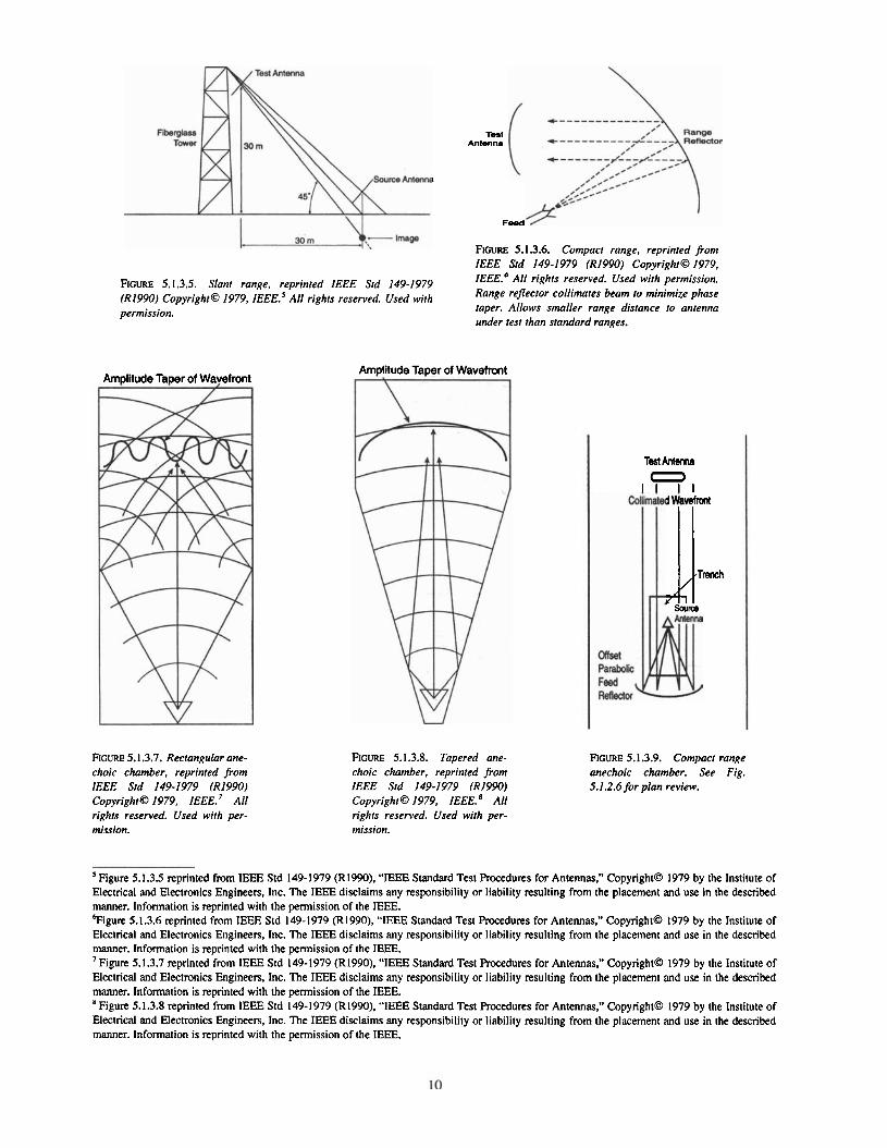
FIGURE 5.1.3.5. Slant range, reprinted IEEE Std 149-1979 (R1990) Copyright@ 1979, IEEE.' All rights reserved. Used with permission.
FIGURE 5.1.3.7. Rectangular ane- choic chamber, reprinted from lEEE Std 149-1979 (R1990) Copyright0 1979, IEEE.' All rights reserved. Used with per- mission.
Test Amenra
Feed
RGURE 5.1.3.6. Compact range, reprinted from IEEE Std 149-1979 (R1990) Copyright0 1979, I E E E . ~ All rights reserved. Used with permission. Range reflector collimates beam to minimize phase raper. Allows smaller range distance to antenna under test than standard ranges.
FIGURE 5.1.3.8. Tapered ane- choic chamber, reprinted from IEEE Std 149-1979 (R1990) Copyright0 1979, I E E E . ~ All rights reserved. Used with per- mission.
Test Antenna 0
I 1 I I Collimated Wavefrmt
FIGURE 5.1.3.9. Compact range anechoic chamber. See Fig. 5.1.2.6 for plan review.
' Figure 5.1.3.5 reprinted From IEEE Std 149-1979 (R1990). "IEEE Standard Test Rocedures for Antennas." Copyright0 1979 by the lnstitute of Electrical and Electronics Engineers. Inc. The IEEE disclaims any responsibility or liability resulting from the placement and use in the described manner. Information is reprinted with the permission of the IEEE. 'Figure 5.1.3.6 reprinted from IEEE Std 149-1979 (R1990). "IEEE Standard Test Rocedures for Antennas," Copyright@ 1979 by the Institute of Electrical and Electronics Engineers, Inc. The IEEE disclaims any responsibility or liability resulting from the placement and use in the described manner. Information is reprinted with the permission of the IEEE. 'Figure 5.1.3.7 reprinted from IEEE Std 149-1979 (R1990). "IEEE Standard Test Rocedures for Antennas." Copyright0 1979 by the Institute of Electrical and Electronics Engineers, Inc. The IEEE disclaims any responsibility or liability resulting from the placement and use in the described manner. Information is reprinted with the permission of the IEEE.
Figure 5.1.3.8 reprinted from IEEE Std 149-1979 (R1990). "IEEE Standard Test Rocedures for Antennas," Copyright@ 1979 by the Institute of Electrical and Electronics Engineers, Inc. The IEEE disclaims any responsibility or liability resulting from the placement and use in the described manner. Information is reprinted with the permission of the IEEE.
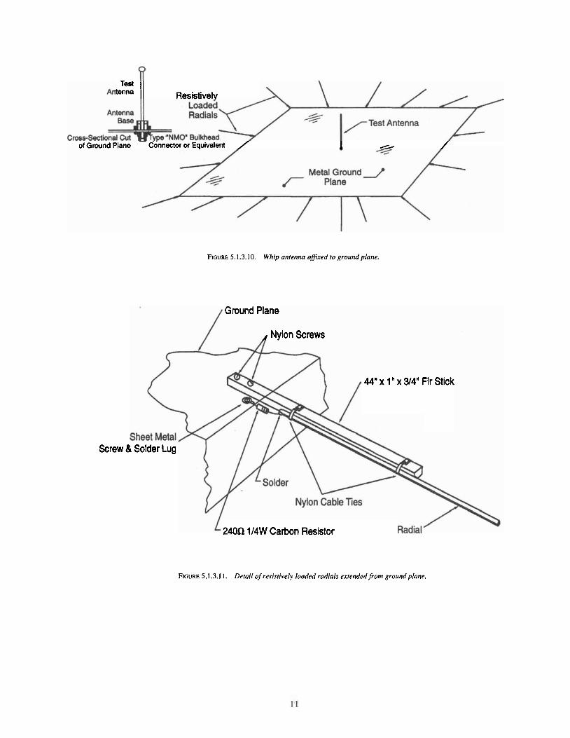
Antenna Resistively Loaded
Antenna Radials
Cross-Sectional Cut ype "NM( - - . of Ground Plane Connect01
-4 3. iY,zy I/~est Antenna
* or Equivalent * - Metal -. Ground J /* / Plane /
FIGURE 5.1.3.10. Whip antenna afixed to ground plane.
Ground Plane
Screw
44" x 1 " x 34' Fir Stick
240Q 114W Carbon Resistor
FIGURE 5.1.3.1 1. Detail of resistively loaded radials extendedfrom ground plane.
5.2.4 Power Meter
The power meter shall measure forward and reflected power in a 50 fl system with full-scale uncertainty of 5 percent or less. It may be a through-line directional power meter, or two power meters attached to a directional coupler, or as part of a vector network analyzer.
5.2.5 Reference Antennas
To determine the realized gain of the antenna under test (AUT), subtract the measured relative gain (in dB) of the standard (STD) monopole reference antenna from the measured relative gain (in dB) of the antenna under test, then add the appropriate gain number from the following tables to that intermediate result, i.e.:
Tables 5.2.5-1 through 5.2.5-5 summarize the gain characteristics of the standard monopole reference antenna. These gain figures include the effects of VSWR mismatch.
TABLE 5.2.5- 1. Gain characteristics for 2.4-meter length1 1.0 cm diameter Type I standard reference monopole antenna.
- -- -- - - -
Frequency (MHz) Gain (dBi}
TABLE 5.2.5-2. Gain characteristics for 1.72-meter lengthll.0 cm diameter Type I standnrd reference monopole antenna.
Frequency (MHz) Gain (dB;)
TABLE 5.2.5-3. Gain characteristics for 0.445-meter length10.48 cm diameter Type / I standard reference monopole antenna.
Frequency (MHz) Gain (dB;}
TABLE 5.2.5-4. Gain characteristics for 0.156-meter length10.48 cm diameter Type Ill standard reference monopole antenna.
Frequency (MHz) Gain (dBi)
TABLE 5.2.5-5. Gain characteristics for 0.0845-meter length10.48 cm diameter Type IV standard reference monopole antenna.
Frequency (MHz) Gain (dBi)
5.3 Rf Performance Tests
5.3.1 Standing Wave Ratio (Voltage Standing Wave Ratio)
Voltage standing wave ratio may be determined by measuring the forward and reflected power and solving the following equation:
v s m - ( f i f + fi) / ( f i f - VE)
where Pf is the forward measured power and P, is the reverse, or reflected measured power. Many network analyzers have provision for measuring and directly displaying VSWR in Cartesian or polar (Smith Chart) form. If the line loss between the antenna under test and the measurement device exceeds 0.5 dB, the measured VSWR must be corrected to compensate for the line loss, which will otherwise make the antenna appear to have superior VSWR than it really has. Ideally, the measurement device should be located as close as possible to the antenna feed point.
5.3.2 Relative Antenna Gain Test
Relative antenna gain of the antenna under test is determined by illuminating a standard gain reference antenna with an electromagnetic wave of a particular frequency, power, and polarization and measuring its voltage or power delivered to a measurement device. This value is compared to that measured after replacing the standard gain reference antenna with the antenna under test and illuminating it under the same conditions of frequency, power, and polarization as before. See section 5.2.5.
5.3.3 Radiation Pattern Test
The basic procedure for performing radiation pattern measurements is fully described in ANSVEEE STD 149-179 (R1990) in various sections. The technique is illustrated in figure 5.3.3.1. Essentially, the source and test antennas are securely affixed to their respective supporting structures in such a way that their mutual polarization is as desired, usually co-polarized. As the antenna under test is rotated about its axis (see fig. 5.3.3.1). a line-of-sight ray originating from the source antenna traces out a path along an imaginary sphere which surrounds the test antenna and rotates with it. This defines the plane of the radiation pattern cut. The voltage or power response of the antenna under test at each angular orientation is mapped to a radial distance as a function of the angle in this plane. This gives an indication of the antenna pattern, or radiation pattern, which shows the response of the antenna to an electromagnetic wave incident from some prescribed direction.
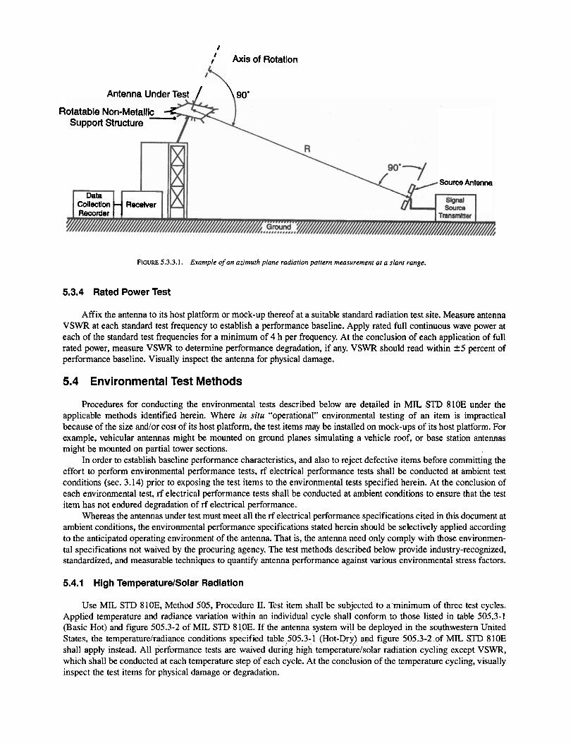
I I
I Axis of Rotation
Antenna Under Test / \ 90.
Rotatable Non-Metallic Support Structure
Source Antenna
FIGURE 5.3.3.1. Example of an azimuth plane radiation pattern measurement at a slant range.
5.3.4 Rated Power Test
Affix the antenna to its host platform or mock-up thereof at a suitable standard radiation test site. Measure antenna VSWR at each standard test frequency to establish a performance baseline. Apply rated full continuous wave power at each of the standard test frequencies for a minimum of 4 h per frequency. At the conclusion of each application of full rated power, measure VSWR to determine performance degradation, if any. VSWR should read within +5 percent of performance baseline. Visually inspect the antenna for physical damage.
5.4 Environmental Test Methods
Procedures for conducting the environmental tests described below are detailed in MIL STD 810E under the applicable methods identified herein. Where in situ "operational" environmental testing of an item is impractical because of the size andlor cost of its host platform, the test items may be installed on mock-ups of its host platform. For example, vehicular antennas might be mounted on ground planes simulating a vehicle roof, or base station antennas might be mounted on partial tower sections.
In order to establish baseline performance characteristics, and also to reject defective items before committing the effort to perform environmental performance tests, rf electrical performance tests shall be conducted at ambient test conditions (sec. 3.14) prior to exposing the test items to the environmental tests specified herein. At the conclusion of each environmental test, rf electrical performance tests shall be conducted at ambient conditions to ensure that the test item has not endured degradation of rf electrical performance.
Whereas the antennas under test must meet all the rf electrical performance specifications cited in this document at ambient conditions, the environmental performance specifications stated herein should be selectively applied according to the anticipated operating environment of the antenna. That is, the antenna need only comply with those environmen- tal specifications not waived by the procuring agency. The test methods described below provide industry-recognized, standardized, and measurable techniques to quantify antenna performance against various environmental stress factors.
5.4.1 High TemperaturelSolar Radiation
Use MIL STD 810E, Method 505, Procedure 11. Test item shall be subjected to a minimum of three test cycles. Applied temperature and radiance variation within an individual cycle shall conform to those listed in table 505.3-1 (Basic Hot) and figure 505.3-2 of MIL STD 81,OE. If the antenna system will be deployed in the southwestern United States, the temperaturelradiance conditions specified table 505.3-1 (Hot-Dry) and figure 505.3-2 of MIL STD 810E shall apply instead. All performance tests are waived during high temperaturelsolar radiation cycling except VSWR, which shall be conducted at each temperature step of each cycle. At the conclusion of the temperature cycling, visually inspect the test items for physical damage or degradation.
5.4.2 Low Temperature
Use MIL STD 810E, Method 502.3, Procedure 11. Test item shall be subjected to a minimum of three test cycles. Applied temperature and humidity variation within an individual cycle shall conform to those listed in tables X (Ambient) (CONUS and Alaska coastal regions) or XI1 (Ambient) (southwestern Alaska) of MIL STD 210C. For deployment in northeastern regions of Alaska, the test item shall be subjected to the constant temperature specified in section 4.3.2 for a like period of time. All performance tests are waived during low temperature exposure except VSWR, which shall be conducted at each temperature step of each cycle. At the conclusion of the low temperature testing, visually inspect the test items for physical damage or degradation.
5.4.3 Blowing Raln
Use MIL STD 810E, Method 506.3, Procedure I. Test item shall be subjected to conditions specified in section 4.3.3 table 4.3.3-1 above. All performance tests are waived during blowing rain exposure except VSWR, which shall be conducted just prior to cessation of this test. At the conclusion of blowing rain testing, visually inspect the test items for physical damage, leakage, or degradation.
5.4.4 Humidity
Use MIL STD 810E, Method 507.3, Procedure 111. All performance tests are waived during aggravated humidity exposure except VSWR, which shall be conducted during the fifth and tenth humidity cycles of this test. At the conclu- sion of humidity testing, visually inspect the test items for physical damage, leakage, or degradation.
5.4.5 Salt Fog
Use MIL !TI'D 810E, Method 509.3, Procedure I. Cycle the test article to alternating 24 h periods of salt fog exposure and standard ambient drying for a minimum of four 24 h periods. All performance tests are waived during salt fog exposure. At the conclusion of salt fog testing, visually inspect the test items for physical damage, corrosion, or degradation.
5.4.6 Sand and Dust
Use MIL STD 810E, Method 510.3, Procedures I and 11. All performance tests are waived during sand and dust exposure. At the conclusion of salt fog testing, visually inspect the test items for physical damage, erosion of surfaces, or degradation.
5.4.7 IcinglFreezing Rain
Use M L r'D 810E, Method 521.1, Procedure I. All performance tests are waived during icing exposure. At the conclusion of icing testing, visually inspect the test items for physical damage.
5.4.8 Vibration
Use MIL STL) 810E, Method 514.3, Procedure I. Depending on host platform, use test conditions 1-3.4.1 (propeller aircraft), 1-3.4.3 (helicopter), 1-3.4.7 (ground mobile), or 1-3.4.8 (marine). All performance tests are waived during vibration testing. At the conclusion of vibration testing, visually inspect the test items for physical damage.
5.4.9 Shock
Whip antennas and other antennas which protrude from the host vehicle more than 30 cm (12 in) shall be firmly affixed to a stationery supporting structure. The antenna shall be repetitively subjected to striking action 30 cm (12 in) above its mounting base by a piston or motor driven impact arm to simulate shock conditions which might be expected when, for example, driving under a low clearance obstruction at a speed of 16 kph (10 mph). The required number of blows shall be 1500. Figure 5.4.9.1 illustrates a possible test fixture for administering this test.
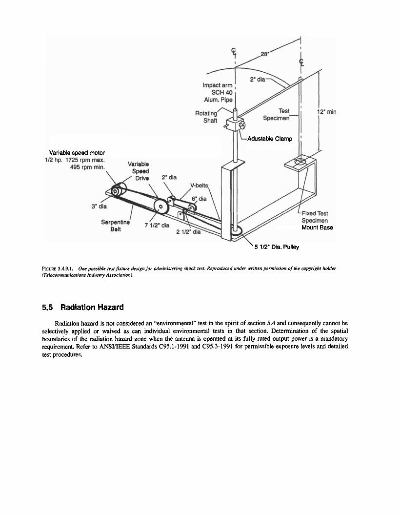
Variable speed motor 112 hp. 1725 rpm max.
Mount Base
FIGURE 5.4.9.1. One possible test ftrture design for administering shock test. Reproduced under written permission of the copyright holder (Telecommunicotiom lndustry Association).
5.5 Radlation Hazard
Radiation hazard is not considered an "environmental" test in the spirit of section 5.4 and consequently cannot be selectively applied or waived as can individual environmental tests in that section. Determination of the spatial boundaries of the radiation hazard zone when the antenna is operated at its fully rated output power is a mandatory requirement. Refer to ANSYIEEE Standards C95.1-1991 and C95.3-1991 for permissible exposure levels and detailed test procedures.
NIJ Standard-0205.01, Standard for Mobile Antennas, May 1989, National Institute of Justice. ANSUIEEE 145-199, IEEE Standard Definitions of Rrms for Antennas. ANSYIEEE 149- 1979 (R1990). IEEE Standard Test Procedures for Antennas. ANSVIEEE C95.1-1991, IEEE Standard for Safety Levels with Respect to Human Exposure to Radio Frequency
Electromagnetic Fields, 3 kHz to 300 GHz. ANSUIEEE C95.3-1991, IEEE Standard Recommended Practice for the Measurement of Potentially Hazardous
Electromagnetic Fields-RF and Microwave. TIAIEIA 222-F? Structural Standards for Steel Antenna Towers and Antenna Supporting Structures. TIAJEIA 29-B-1 , I0 Minimum Standards for Communications Antennas, Part 11-Mobile Antennas. MIL SI'D 210C, Climatic Information to Determine Design and Test Requirements for Military Systems and
Equipment. MIL SI'D 810E, Environmental Test Methods and Engineering Guidelines. Federal Communications Commission Report and Order 96-26 (1996 Aug. I), "Guidelines for Evaluating the
Environmental Effects of Radio Frequency Radiation."
6 U.S. GOVERNMENT PRINTING OFFICE: 1998 - 432 -178 1 80071
To purchase the complete text of any TIA document, call Global Engineering Documents at 1-800-854-7179 or send a facsimile to 1-303-397- 2740.
'O Ibid.
U. S. Department of Justice Office of Justice Programs
8 10 Seventh Street N. W. Washington, DC 2053 1
Janet Reno Attorney General
U.S. Department of Justice
Raymond C. Fisher Associate Attorney General
Laurie Robinson Assistant Attorney General
Noel Brennan Deputy Assistant Attorney General
Jeremy Travis Director, National Institute of Justice
Department of Justice Response Center: 800-42 1-6770
Office of Justice Programs World Wide Web Site: http://www. ojp. usdoj.gov
National Institute of Justice World Wide Web Site:
http://www.ojp. usdoj.gov/nij