Embed Size (px)
Citation preview


US ARMY LIGHT WHEEL VEHICLE MECHANIC MOS 63B SKILL LEVEL 3 COURSE
WHEELED VEHICLE BRAKING SYSTEMS
SUBCOURSE NO. OD1008
US Army Ordnance Center and School
Five Credit Hours
GENERAL The Wheeled Vehicle Braking Systems subcourse, part of the Light Wheel Vehicle Mechanic MOS 63B Skill Level 3 course , is designed to teach the knowledge necessary to develop the skills for servicing and maintaining braking systems. Information is provid ed on the principles and operation of mechanical, hydraulic, air-hydraulic, air, and electric brake systems. Information is al so provided on the inspection of these systems. This subcourse is pre sented in three lessons, each lesson corresponding to a terminal ob jective as indicated below. Lesson 1: FUNDAMENTALS OF WHEELED VEHICLE BRAKING S YSTEMS TASK: Describe the principles of automotive brake s ystems and the construction and operation of mechanical and hydrau lic brake systems. CONDITIONS: Given information on the principles of braking, and the construction and operation of internal and external drum brakes, disk brakes, mechanical and hydraulic brake systems, and parking brakes. STANDARDS: Answer 70 percent of the multiple-choice test items covering fundamentals of wheeled vehicle braking sy stems. Lesson 2: AIR-HYDRAULIC BRAKE SYSTEMS TASK: Describe the principles, construction, and op eration of air-hydraulic brake systems. CONDITIONS: Given information on the purpose, compo nents, operation, and inspection of air-hydraulic brake systems. STANDARDS: Answer 70 percent of the multiple-choice test items covering fundamentals of air-hydraulic brake system s.
i

Lesson 3: AIR-BRAKE SYSTEMS TASK: Describe the principles, construction, and op eration of straight air-brake systems. CONDITIONS: Given information on the components and operation of straight air-brake systems. STANDARDS: Answer 70 percent of the multiple-choice test items covering fundamentals of air-brake systems. ii
TABLE OF CONTENTS Section Page TITLE PAGE ........................................ ............ i TABLE OF CONTENTS ................................. ............ iii INTRODUCTION TO WHEELED VEHICLE BRAKING SYSTEMS ... ............ vi Lesson 1: FUNDAMENTALS OF WHEELED VEHICLE BRAKING SYSTEMS Learning Event 1: Describe the Principles of Braking and Braking Systems ................... ........ 1 Learning Event 2: Describe the Construction and Operation of Hydraulic Brake Systems ......... ........ 24 Learning Event 3: Describe Inspection Procedures for Hydraulic Brake Systems ........... ........ 30 Practice Exercise ................................ ........ 35 Answers to Practice Exercise ..................... ........ 36 Lesson 2: AIR-HYDRAULIC BRAKE SYSTEMS Learning Event 1: Describe the Components of the Air-Hydraulic Brake System ................ ........ 37 Learning Event 2: Describe the Operation of the Air-Hydraulic Brake System ................ ........ 48 Learning Event 3: Describe Inspection Procedures for the Air-Hydraulic Brake System .... ........ 56 Practice Exercise ................................ ........ 63 Answers to Practice Exercise ..................... ........ 64
iii

Section Page Lesson 3: AIR-BRAKE SYSTEMS Learning Event 1: Describe the Components of the Straight Air-Brake System ................. ........ 65 Learning Event 2: Describe the Operation of the Straight Air-Brake System ................. ........ 73 Learning Event 3: Describe Inspection Procedures for the Straight Air-Brake System ..... ........ 80 Practice Exercise ................................ ........ 87 Answers to Practice Exercise ..................... ........ 88
*** IMPORTANT NOTICE ***
THE PASSING SCORE FOR ALL ACCP MATERIAL IS NOW 70%.
PLEASE DISREGARD ALL REFERENCES TO THE 75% REQUIREMENT.
iv
THIS PAGE INTENTIONALLY LEFT BLANK
v
INTRODUCTION TO WHEELED VEHICLE BRAKING SYSTEMS Up to this point, each one of our subcourses has co vered all the things that were needed to make a vehicle go forwar d and backward. We now know that an operator has controls to make t his equipment go fast or slow; to the right or left; through mud, sn ow, sand; and on level roads. But what does the operator do if a ch ild runs out in front of this moving vehicle, or when traveling on a road a point is reached where a bridge is washed out? The answer i s that the operator must have one or more controls that will b ring the vehicle to a stop rapidly and with a small amount of effort . The braking system provides these controls. Braking is the use of friction to slow a vehicle, b ring it to a halt, or hold it in a standing position. A brake is a de vice that is secured to the vehicle axle housings, which do not rotate, and is used to slow down or hold the wheels, which do rota te. When the rotating parts are brought in contact with the nonr otating parts, the friction caused by the rubbing creates the braking action. All vehicles must be built so they meet the minimum braking requirements. For many years it has been a set sta ndard that a braking system must be able to stop a vehicle trave ling 20 miles per hour (MPH) within 30 feet. You must remember, howe ver, this does not mean the vehicle will always stop in 30 feet. It d oes mean that if the tires could get enough traction on the road, th e brakes must hold well enough to stop it in that distance. To get an idea of how much power is involved in braking systems, imagine a 10, 000-pound truck traveling 50 MPH being braked at the rate discussed above. The energy required to do the braking would be equivale nt to 500 horsepower (HP). This is much more than the vehicl e engine could ever produce. Most of the braking systems on moder n passenger cars can handle about eight times the power developed by the engine. This subcourse is designed to provide you with a kn owledge of how braking system components operate. vi
Lesson 1/Learning Event 1
LESSON 1 FUNDAMENTALS OF WHEELED VEHICLE BRAKING SYSTEMS
TASK Describe the principles of automotive brake systems and the construction and operation of mechanical and hydrau lic brake systems. CONDITIONS Given information on the principles of braking and the construction and operation of internal and external drum brakes, disk brakes, mechanical and hydraulic brake systems, and parking brakes. STANDARDS Answer 70 percent of the multiple-choice test items covering fundamentals of wheeled vehicle braking systems. REFERENCES TM 9-8000 Learning Event 1: DESCRIBE THE PRINCIPLES OF BRAKING AND BRAKING SYST EMS INTRODUCTION Braking action on wheeled vehicles is the use of a controlled force to hold, stop, or reduce the speed of a vehicle. M any factors must be considered when designing the braking system for an automotive item. The vehicle weight, size of tires, and type of suspension are but a few that influence the design of a system.
1
Lesson 1/Learning Event 1 The power needed to brake a vehicle is equal to tha t needed to make it go. However, for safety reasons, brakes must be able to stop the car in a very short distance. As an example, a pas senger car equipped with an 80-HP engine can normally accelera te from a standstill to 60 MPH in about 36 seconds. On the o ther hand, the brakes must be able to decelerate the vehicle from 60 MPH to a stop in 4 1/2 seconds. You can therefore see the brakin g force is about eight times greater than the power developed by the engine. Each part in the braking system must operate with a very positive action to accomplish this tremendous braking effort . The job of a wheeled vehicle mechanic is to maintain the braking components in a state of repair that ensures serviceable brakes whe n needed. For you to keep brake system components in a working shape, you must understand how the system works. In this lesson, w e will discuss the principles of operation for components contained in various types of braking systems. Braking action is the use of a controlled force to slow the speed of or stop a moving object, in this case a vehicle. I t is necessary to know what friction is to understand braking action. Friction is the resistance to movement between two surfaces or objects that are touching each other. An example o f friction is the force which tries to stop your hand as you apply pr essure and slide it across a table or desk. This means that by forc ing the surface of an object that is not moving (stationary) against a moving object's surface, the resistance to movement or the rubbing action between the two surfaces of the objects will slow down the movi ng surface. Automotive vehicles are braked in this manner. 2

Lesson l/Learning Event 1 PRINCIPLES OF BRAKING
FIGURE 1. DEVELOPMENT OF FRICTION AND HEAT. Brakes on early motor vehicles were nothing more th an modified wagon brakes used on horse-drawn wagons. These were a ha nd-operated, mechanical, lever-type brakes that forced a piece o f wood against one or more of the wheels. This caused friction or a d rag on the wheel or wheels. There is also friction between the wheel and ground that tries to prevent the wheel from sliding or skidding on the g round. When a vehicle is moving, there is a third force present. This force is known as kinetic energy. This is the name given th e force that tries to keep any object in motion once it has started mo ving.
3

Lesson 1/Learning Event 1 When the brakes are applied, the wheel will either roll or skid, depending on which is greater, the friction between the braking surfaces or between the wheel and the road. Maximu m retardation (slowing down) is reached when friction between the brake surfaces is just enough to almost lock the wheel. At this time , friction between the brake surfaces and wheel and road are almost th e same. This is all the friction that can be used in retarding (slo wing down) the motion of the vehicle. The amount of friction betw een the road and the wheel is what limits braking. Should friction between the braking surfaces go beyond this, the braking surfac es will lock and the wheels will skid. When a wheel rolls along a road, there is no moveme nt between (relative motion) the wheel and road at the point w here the wheel touches the road. This is because the wheel rolls on the road surface; but, when a wheel skids, it slides over th e surface of the road, and there is relative motion because the whee l is not turning while moving over the road. When a wheel skids, fr iction is reduced, which decreases the braking effect. However, brake s are made so that the vehicle operator is able to lock the wheels if enough force to the brake lever or pedal is applied. 4

Lesson 1/Learning Event 1 BRAKING REQUIREMENTS
FIGURE 2. BRAKING REQUIREMENTS.
Most of us know that to increase a vehicle's speed requires an increase in the power output of the engine. It is just as true that an increase in speed requires an increase in the br aking action necessary to bring a vehicle to a stop. Brakes mus t not only be able to stop a vehicle, but must stop it in as short a d istance as possible. Because brakes are expected to decelerat e (slow down) a vehicle at a faster rate than the engine can accele rate it, they must be able to control a greater power than that develo ped by the engine. This is the reason that well-designed, powerful bra kes have to be used to control the modern high-speed motor vehicle . The time needed to stop is one-eighth the time needed to accelerate from a standing start. The brakes then can handle eight times the power developed by the engine.
5
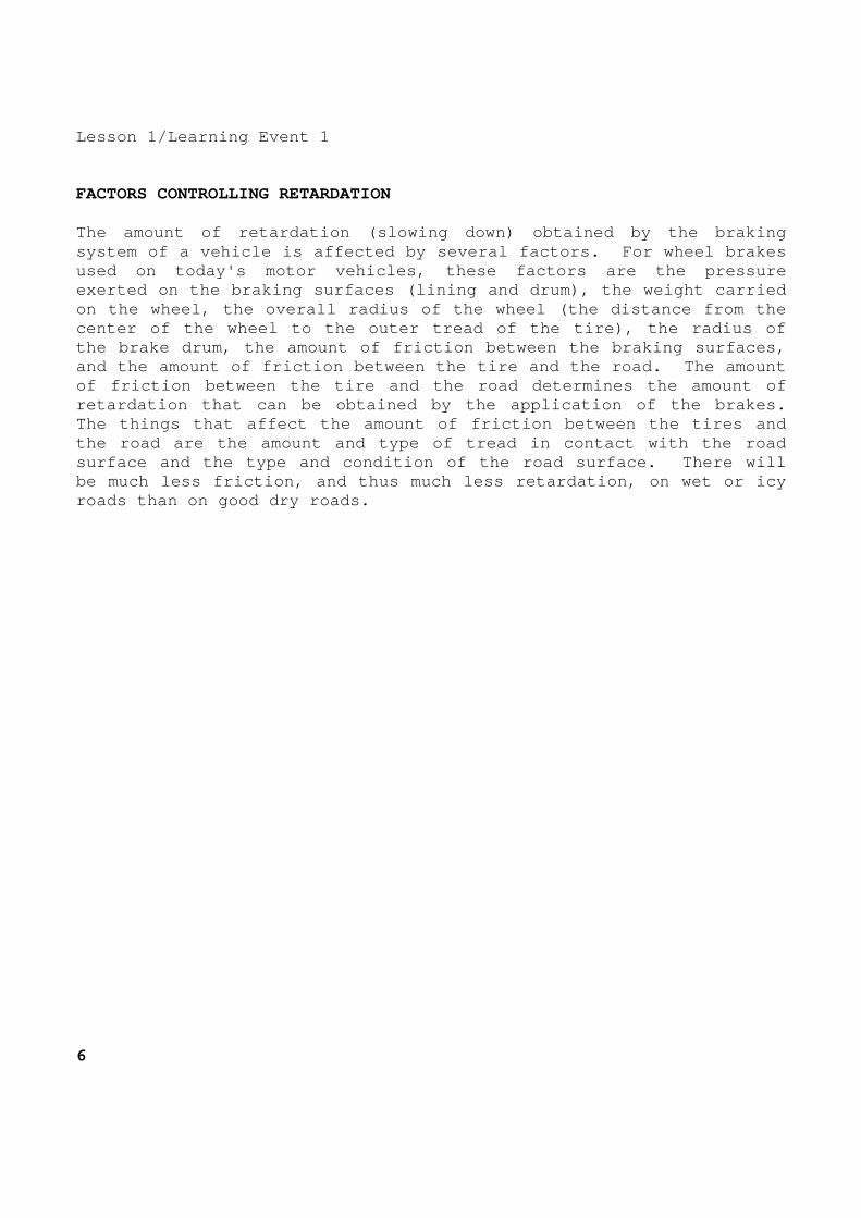
Lesson 1/Learning Event 1 FACTORS CONTROLLING RETARDATION The amount of retardation (slowing down) obtained b y the braking system of a vehicle is affected by several factors. For wheel brakes used on today's motor vehicles, these factors are t he pressure exerted on the braking surfaces (lining and drum), the weight carried on the wheel, the overall radius of the wheel (the distance from the center of the wheel to the outer tread of the tire) , the radius of the brake drum, the amount of friction between the braking surfaces, and the amount of friction between the tire and the road. The amount of friction between the tire and the road determine s the amount of retardation that can be obtained by the application of the brakes. The things that affect the amount of friction betwe en the tires and the road are the amount and type of tread in contac t with the road surface and the type and condition of the road surf ace. There will be much less friction, and thus much less retardati on, on wet or icy roads than on good dry roads. 6
Lesson 1/Learning Event 1 DRIVER'S REACTION TIME
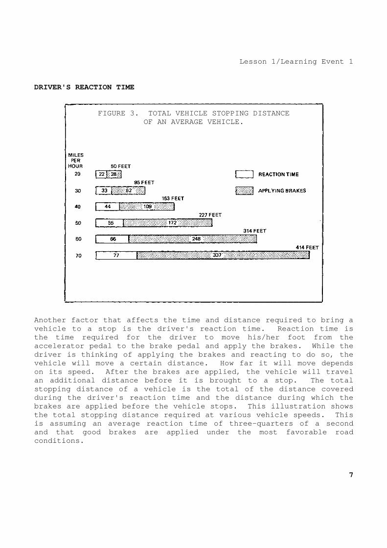
FIGURE 3. TOTAL VEHICLE STOPPING DISTANCE
OF AN AVERAGE VEHICLE. Another factor that affects the time and distance r equired to bring a vehicle to a stop is the driver's reaction time. R eaction time is the time required for the driver to move his/her fo ot from the accelerator pedal to the brake pedal and apply the brakes. While the driver is thinking of applying the brakes and react ing to do so, the vehicle will move a certain distance. How far it w ill move depends on its speed. After the brakes are applied, the ve hicle will travel an additional distance before it is brought to a st op. The total stopping distance of a vehicle is the total of the distance covered during the driver's reaction time and the distance during which the brakes are applied before the vehicle stops. This illustration shows the total stopping distance required at various veh icle speeds. This is assuming an average reaction time of three-quart ers of a second and that good brakes are applied under the most fav orable road conditions.
7

Lesson 1/Learning Event 1
EXTERNAL-CONTRACTING AND INTERNAL-EXPANDING BRAKES
FIGURE 4. EXTERNAL-CONTRACTING AND INTERNAL-EXPAND ING BRAKES. There are several types of braking systems. All sy stems require the use of a rotating (turning) unit and a nonrotating unit. Each of these units contains braking surfaces that, when ru bbed together, give the braking action. The rotating unit on mili tary wheeled vehicle brakes consists of a drum secured to the wh eel. The nonrotating unit consists of brake shoes and the li nkage needed to apply the shoes to the drum. Brakes are either the external-contracting or internal-expanding type, depending o n how the nonrotating braking surface is forced against the r otating braking surface. 8
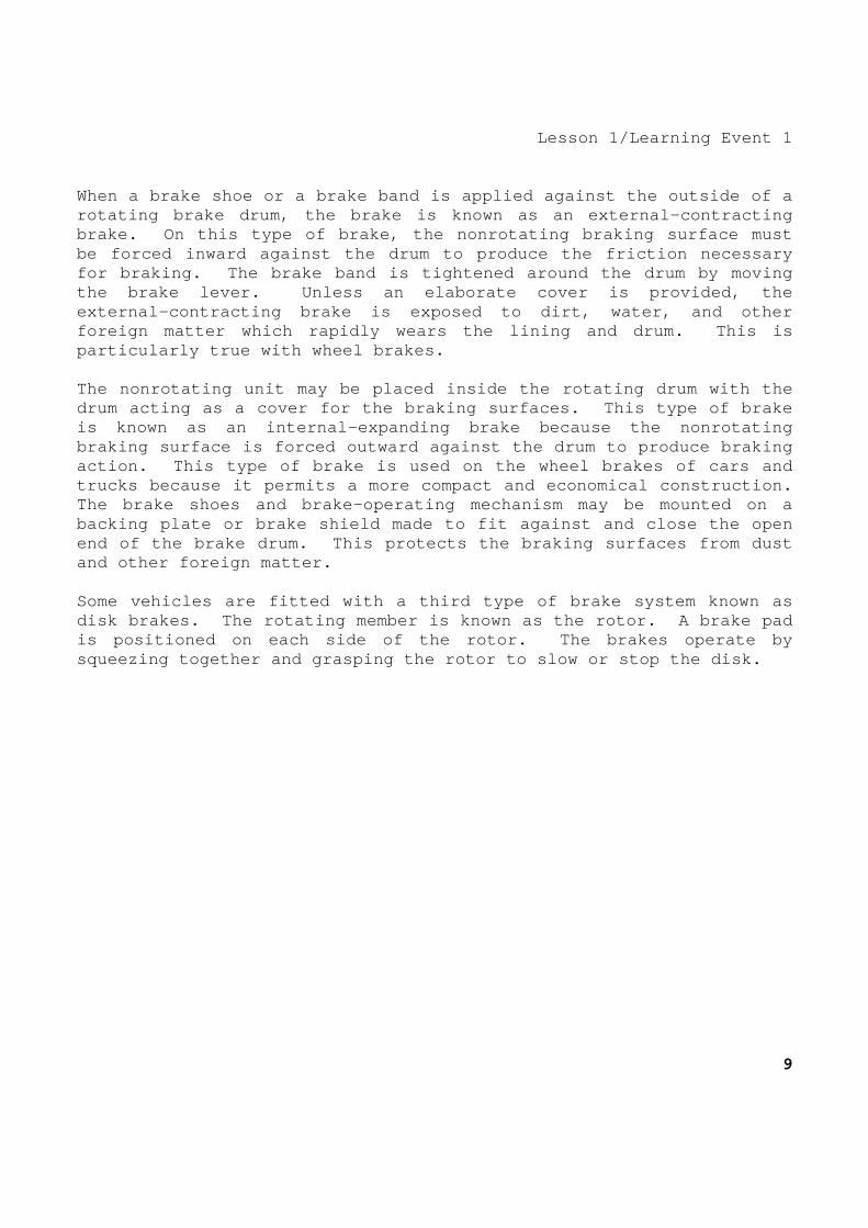
Lesson 1/Learning Event 1 When a brake shoe or a brake band is applied agains t the outside of a rotating brake drum, the brake is known as an exter nal-contracting brake. On this type of brake, the nonrotating brak ing surface must be forced inward against the drum to produce the fr iction necessary for braking. The brake band is tightened around th e drum by moving the brake lever. Unless an elaborate cover is prov ided, the external-contracting brake is exposed to dirt, wate r, and other foreign matter which rapidly wears the lining and d rum. This is particularly true with wheel brakes. The nonrotating unit may be placed inside the rotat ing drum with the drum acting as a cover for the braking surfaces. T his type of brake is known as an internal-expanding brake because the nonrotating braking surface is forced outward against the drum to produce braking action. This type of brake is used on the wheel br akes of cars and trucks because it permits a more compact and econom ical construction. The brake shoes and brake-operating mechanism may b e mounted on a backing plate or brake shield made to fit against a nd close the open end of the brake drum. This protects the braking s urfaces from dust and other foreign matter. Some vehicles are fitted with a third type of brake system known as disk brakes. The rotating member is known as the r otor. A brake pad is positioned on each side of the rotor. The brake s operate by squeezing together and grasping the rotor to slow o r stop the disk.
9
Lesson 1/Learning Event 1 BRAKE DRUMS
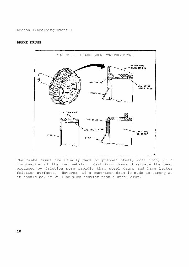
FIGURE 5. BRAKE DRUM CONSTRUCTION.
The brake drums are usually made of pressed steel, cast iron, or a combination of the two metals. Cast-iron drums dis sipate the heat produced by friction more rapidly than steel drums and have better friction surfaces. However, if a cast-iron drum is made as strong as it should be, it will be much heavier than a steel drum. 10

Lesson 1/Learning Event 1 To provide light weight and enough strength, some d rums are made of steel with a cast-iron liner for the braking surfac e. This type is known as a centrifuse brake drum. Cooling ribs are sometimes added to the outside of the drum to give more strength an d better heat dissipation. Braking surfaces of drums may be grou nd, or they may be machined to a smooth finish. For good braking action, the drum should be perfect ly round and have a uniform surface. Brake drums become "out of roun d" from pressure exerted by the brake shoes or bands and from the he at produced by the application of the brakes. The brake drum surface becomes scored when it is worn by the braking action. When the su rface is badly scored or the drum is out of round, it is necessary to replace the drum or regrind it or turn it down in a lathe until the drum is again smooth and true.
11

Lesson 1/Learning Event 1 BRAKE SHOES
FIGURE 6. BRAKE SHOES AND BRAKE LININGS.
Brake shoes are made of malleable iron, cast steel, drop-forged steel, pressed steel, or cast aluminum. Pressed st eel is usually used because it is cheaper to produce in large quan tities. Steel shoes expand at approximately the same rate as the drum when heat is produced by brake application, thereby maintaining the clearance between the brake drum and the brake shoe under mos t conditions. 12

Lesson l/Learning Event 1 A friction lining riveted or bonded to the face of the shoe makes contact with the inner surface of the brake drum wh en the brake is applied. On the riveted-type lining, brass rivets are usually used because brass does not unduly score the drum when t he lining is worn. Aluminum rivets are not very satisfactory because t hey are corroded very readily by salt water. The bonded lining is n ot riveted but is bonded directly to the shoe with a special cement. Differences in brake design and conditions of opera tion make it necessary to have various types of brake linings.
- The molded brake lining is made of dense, hard, c ompact materials and is cut into blocks to fit different s izes of brake shoes. Its frictional qualities are low beca use it has a smooth surface, but it dissipates heat rapidly an d wears longer than the woven type.
- The woven brake lining is made of asbestos fiber, cotton
fiber, and copper or bronze wire. After being wove n, the lining is treated with compounds intended to lessen the effects of oil and water if they should come in con tact with the lining. However, oil, in particular, will redu ce the frictional quality of the lining even after treatme nt. The lining is also compressed and heat treated before b eing installed. The main advantage of a woven lining is its frictional qualities. However, it does not dissipa te heat as rapidly or wear as well as molded brake linings. T his type of lining is generally not used in automotive vehicles .
13

Lesson 1/Learning Event 1 ROTATING AND NONROTATING UNITS The brake drum is mounted directly onto the wheel a nd provides the rotating braking surface. The brake shield, someti mes known as the backing plate or dust shield, is mounted on some fi xed structure such as the axle housing. The brake shield forms a supp ort for the nonrotating braking surface (brake shoes) and its o perating mechanism. The brake shoes may be anchored to the brake shield by separate pins or the same pin. Springs or clips are usually used to hold the shoes close to the brake shield and to prevent them from rattling. A fairly strong retracting spring is hooked between t he shoes to pull them away from the drum when the brakes are release d. With a mechanical hookup, pressure can be applied to the b rake shoes by means of a cam, toggle, or double-lever arrangement . A cam turned by a small lever is the method most frequently used. Turning the cam by the lever tends to spread the brake shoes and pu sh them outward against the drum. With the hydraulic system, press ure is applied to the brake shoes by means of a cylinder and pistons. 14
Lesson 1/Learning Event 1 SELF-ENERGIZING ACTION
FIGURE 7. SELF-ENERGIZING AND SERVO ACTION.
15
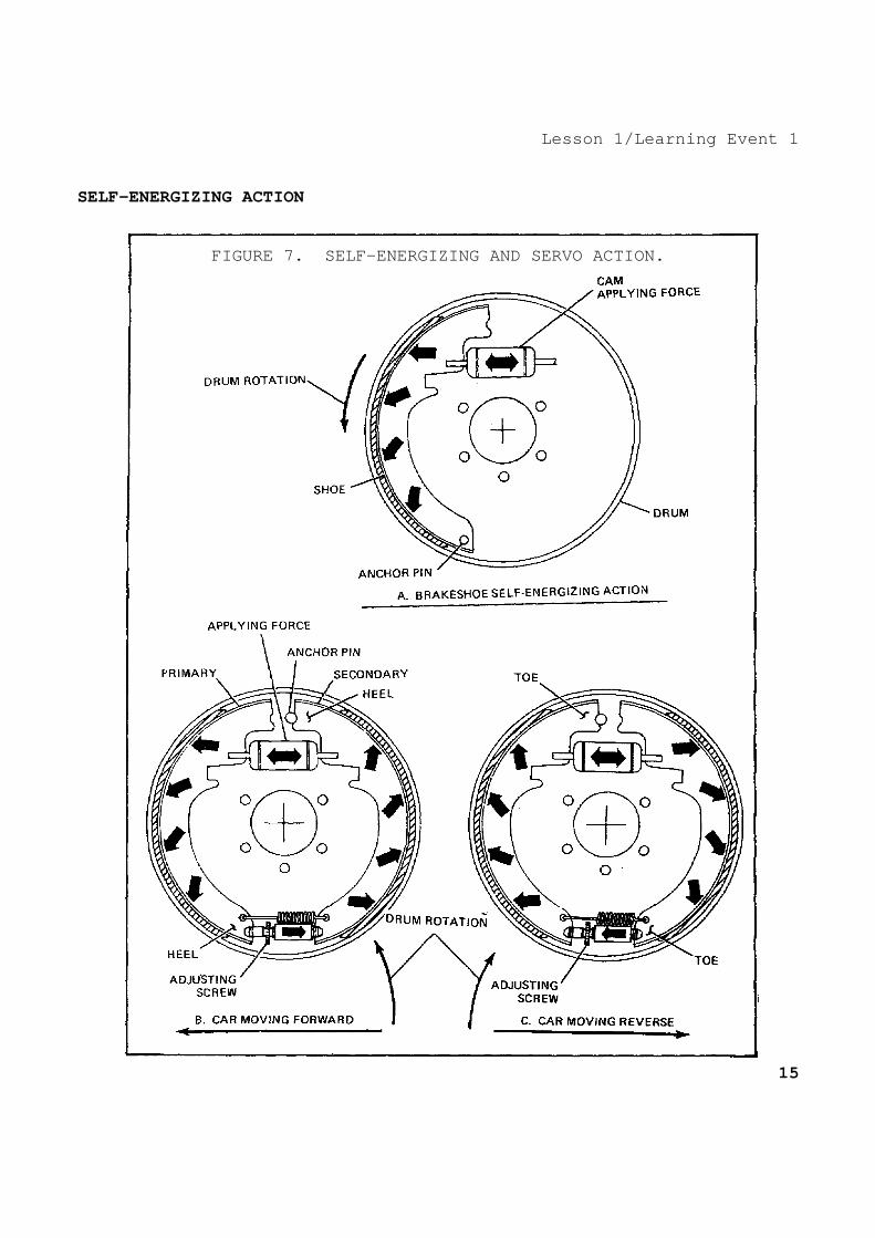
Lesson 1/Learning Event 1 The brake operating linkage alone does not provide enough mechanical advantage for good braking. Some way of increasing the pressure of the brake shoes is needed. A self-energizing actio n can be used to do this, once the setting of the shoes is started b y the movement of the linkage. There are several variations of this self-energizing action, but it is always done by the shoes themselv es as they tend to turn with the turning drum. When the brake shoe is anchored and the drum turns in the direction shown, the shoe will tend to turn with the drum whe n it is forced against the drum. Friction is trying to cause the shoe to turn with the drum. When this happens, the shoe pushes again st the anchor pin. Since the pin is fixed to the brake shield, this pr essure tends to wedge the shoe between the pin and drum. As the ca m increases the pressure on the shoes, the wedging action increases and the shoe is forced still more tightly against the drum to incre ase the friction. This self-energizing action results in more braking action than could be obtained by the pressure of the cam against the shoes alone. Brakes making use of this principle to increase pre ssure on the braking surfaces are known as self-energizing brake s. It is very important that the operator control the total braking action at all times, which means the self-energizin g action should increase only upon the application of more pressure on the brake pedal. The amount of self-energizing action availa ble depends mainly on the location of the anchor pin. As the pin is m oved toward the center of the drum, the wedging action increases un til a point is reached where the shoe will automatically lock. Th e pin must be located outside this point so that the operator can control the braking. When two shoes are anchored on the bottom of the br ake shield, self-energizing action is effective on only one shoe. T he other shoe tends to turn away from its pivot. This reduces i ts braking action. When the wheel is turning in the opposite direction , the self-energizing action is produced on the opposite shoe. 16

Lesson 1/Learning Event 1 Two shoes can be mounted so that self-energizing ac tion is effective on both. This is done by pivoting the shoes to eac h other and leaving the pivot free of the brake shield. The on ly physical effort required is for operating the first or primary shoe . Both shoes then apply more pressure to the braking surfaces without an increase in pressure on the brake pedal. The anchor pins are f itted into slots in the free ends of the brake shoes. This method o f anchoring allows the shoes to move and expand against the drum when the brakes are applied. The self-energizing action of the primary shoe is transmitted through the pivot to the secondary shoe . Both shoes will tend to turn with the drum and will be wedged again st the drum by one anchor pin. The other anchor pin will cause a simi lar action when the wheel is turning in the opposite direction. Another type of brake shoe that has been used consi sts of two links anchored together on the brake shield with the end of each link pivoted to one of the brake shoes. This allows mor e even application of the braking surface because of the freedom of mo vement for the brake shoes. Each shoe is self-energizing in oppos ite directions.
17
Lesson 1/Learning Event 1 DISK BRAKES
FIGURE 8. DISK BRAKE ASSEMBLY.
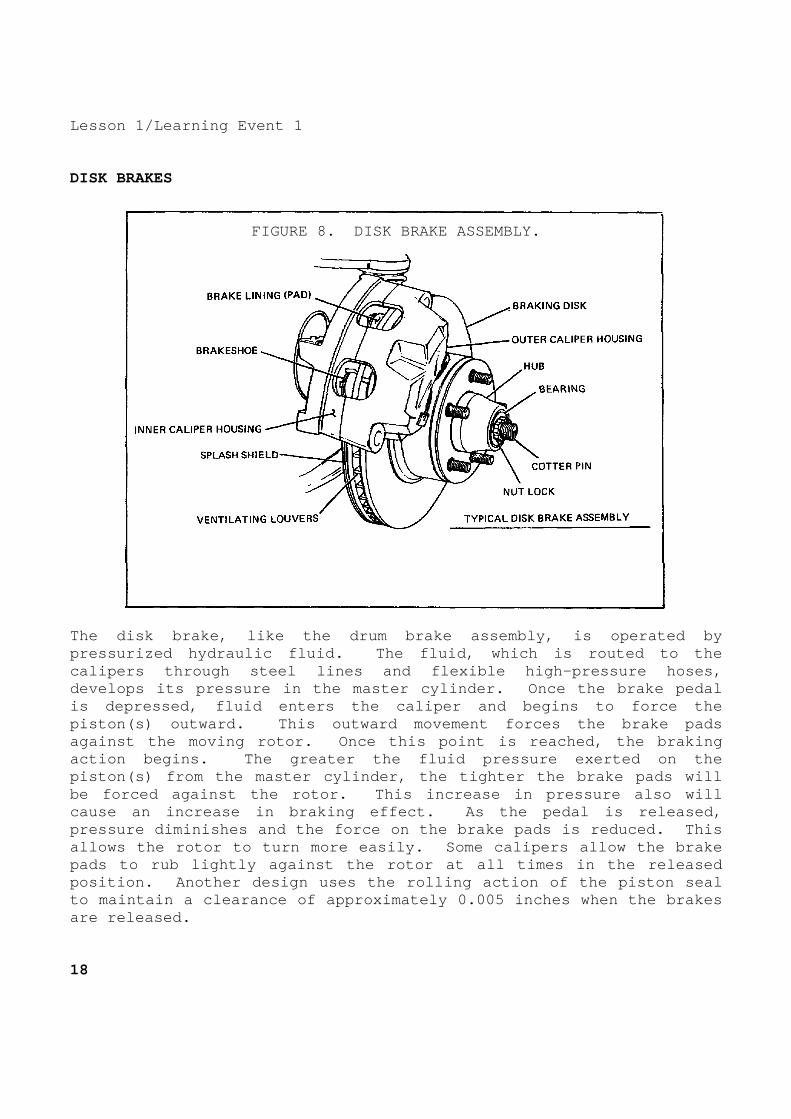
The disk brake, like the drum brake assembly, is op erated by pressurized hydraulic fluid. The fluid, which is r outed to the calipers through steel lines and flexible high-pres sure hoses, develops its pressure in the master cylinder. Once the brake pedal is depressed, fluid enters the caliper and begins t o force the piston(s) outward. This outward movement forces th e brake pads against the moving rotor. Once this point is reach ed, the braking action begins. The greater the fluid pressure exer ted on the piston(s) from the master cylinder, the tighter the brake pads will be forced against the rotor. This increase in pres sure also will cause an increase in braking effect. As the pedal is released, pressure diminishes and the force on the brake pads is reduced. This allows the rotor to turn more easily. Some caliper s allow the brake pads to rub lightly against the rotor at all times in the released position. Another design uses the rolling action o f the piston seal to maintain a clearance of approximately 0.005 inch es when the brakes are released. 18
Lesson 1/Learning Event 1 Comparison to Drum Brakes Both the disk and brake drum assemblies used on mod ern vehicles are well-designed systems. Each system exhibits certai n inherent advantages and disadvantages. The most important p oints of interest are discussed below. One major factor that must be discussed in automotive brakes, as well as all other brake syste ms, is the system's ability to dissipate heat. As discussed p reviously, the byproduct of friction is heat. Because most brake systems use this concept to develop braking force, it is highly desi rable for brake systems to dissipate heat as rapidly and efficientl y as possible. The disk brake assembly, because of its open design , has the ability to dissipate heat faster than the brake drum. This feature makes the disk brake assembly less prone to brake fade due to a buildup of excess heat. The disk assembly also may have addit ional heat transfer qualities due to the use of a ventilated r otor. This type of rotor has built-in air passages between friction surfaces to aid in cooling. While the brake drum assembly requires an initial s hoe-to-drum clearance adjustment and periodic checks, the disk brake assembly is self-adjusting and maintains proper adjustment at a ll times. The disk assembly automatically compensates for lining wear by allowing the piston in the caliper to move outward, thereby taking up excess clearance between pads and rotor. The disk system is fairly simplistic in comparison to the drum system. Due to this design and its lack of moving parts and springs, the disk assembly is less likely to malfunction. O ver-hauling the disk brake assembly is faster because of its simpli stic design. It also is safer due to the fact that the disk brake a ssembly is open and asbestos dust from linings is less apt to be ca ught in the brake assembly. Like brake drums, rotors may be machined if excessive scoring is present. Rotors also are stamped with a minimum thickness dimension which should not be exceeded. The drum b rake assembly requires that the drum be removed for lining inspec tion, while some disk pads have a built-in lining wear indicator tha t produces an audible high-pitch squeal when linings are worn exc essively. This harsh squeal is a result of the linings wearing to a point, allowing a metal indicator to rub against the rotor as the w heel turns. Because of its small frictional area and lack of se lf-energizing and servo effect, the disk brake assembly requires the use of an auxiliary power booster to develop enough hydraulic pressure for satisfactory braking.
19

Lesson 1/Learning Event 1 Floating Caliper The floating caliper is designed to move laterally on its mount. This movement allows the caliper to maintain a cent ered position with respect to the rotor. This design also permits the braking force to be applied equally to both sides of the rotor. The floating caliper usually is a one-piece solid construction and uses a single piston to develop the braking force. This type of caliper op erates by pressurized hydraulic fluid like all other hydrauli c calipers. The fluid under pressure first enters the piston cavity and begins to force the piston outward. As this happens, the bra ke pad meets the rotor. Additional pressure then forces the caliper assembly to move in the opposite direction of the piston, thereby fo rcing the brake pad on the opposite side of the piston to engage th e rotor. As pressure is built up behind the piston, it then for ces the brake pads tighter against the rotor to develop additional bra king force. Fixed Caliper The fixed caliper is mounted rigidly to the spindle or splash shield. In this design, the caliper usually is made in two pieces and has either two, three, or four pistons in use. The pis tons, which may be made of cast iron, aluminum, or plastic, are provid ed with seals and dust boots and fit snugly in bores machined in the caliper. The centering action of the fixed caliper is accomplish ed by the pistons as they move in their bores. If the lining should wear unevenly on one side of the caliper, the excess clearance would be taken up by the piston simply by moving further out in its bore . As the brakes are applied, the fluid pressure enters the caliper on one side and is routed to the other through an internal passageway or an external tube connected to the opposite half of the caliper. As pressure is increased, the pistons force the brake pads against the rotors evenly and therefore maintain an equal amount of pressure on both sides of the rotor. As discussed above, the fixed calipers use a multi- piston design to provide the braking force. The fixed calipers may be designed to use two, three, or four pistons. The dual-piston desig n provides a slight margin of safety over a single-piston floati ng caliper. In the event of a piston seizing in the caliper, the s ingle-piston caliper would be rendered useless, while the dual-p iston design would still have one working piston to restore some braki ng ability. The three- and four-piston design provides for the use of a large brake lining. The brake force developed may now be sprea d over a larger area of the brake pad. 20

Lesson 1/Learning Event 1 MECHANICAL BRAKE SYSTEMS On wheeled vehicles, the energy supplied by the ope rator's foot pushing down on the brake pedal is transferred to t he brake mechanism on the wheels by various means. A mechanical hooku p was used on the first motor vehicles. Now, mechanically-operated b raking systems are practically obsolete. However, mechanical hookups are still used for a part of the braking systems in many vehicles. PARKING BRAKE The parking brake (auxiliary brake) is generally us ed to lock the rear wheels or propeller shafts of a vehicle to pre vent the vehicle from rolling when it is parked. It can also be use d to stop the vehicle in an emergency if the service brakes fail. For this reason, the parking brake is sometimes referred to as the e mergency brake.
21
Lesson l/Learning Event 1 CONSTRUCTION
FIGURE 9. EXTERNAL-CONTRACTING BRAKE.
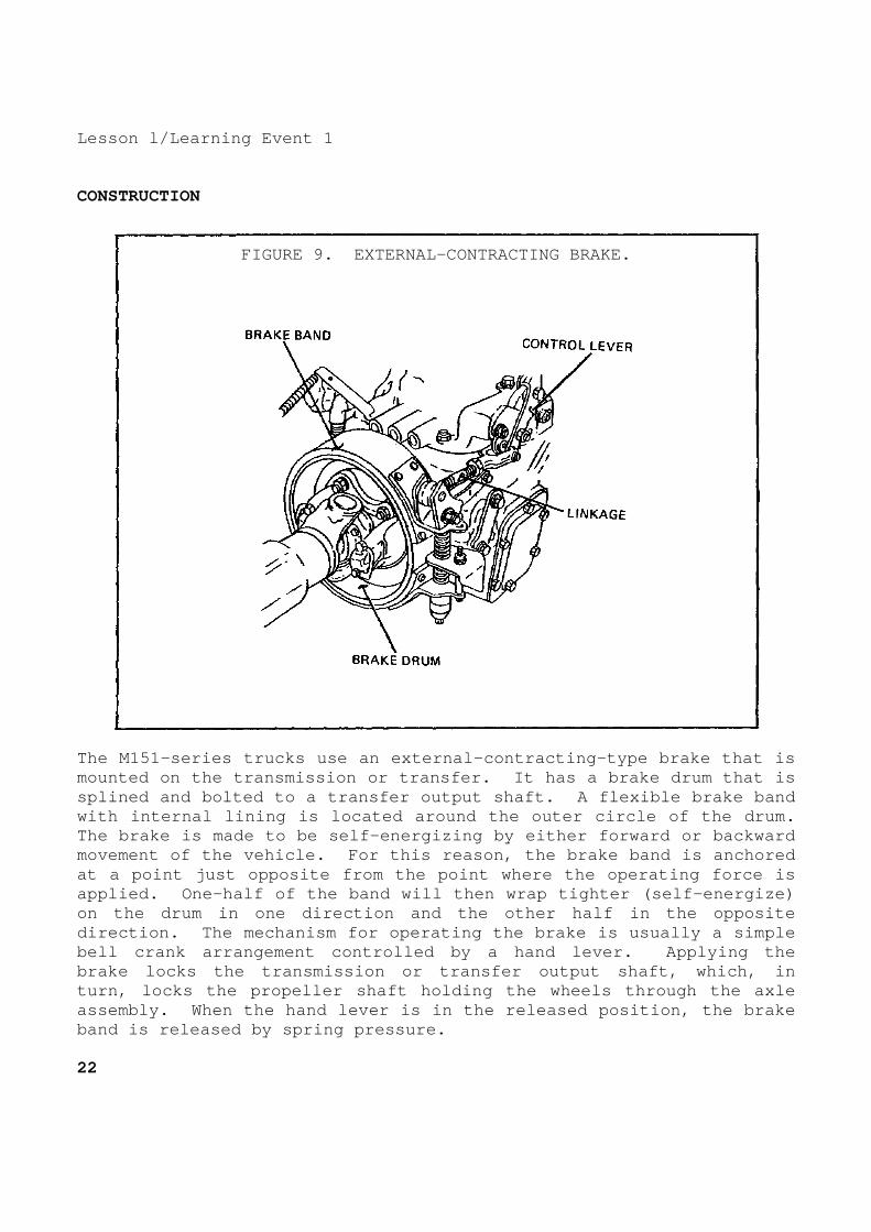
The M151-series trucks use an external-contracting- type brake that is mounted on the transmission or transfer. It has a brake drum that is splined and bolted to a transfer output shaft. A f lexible brake band with internal lining is located around the outer ci rcle of the drum. The brake is made to be self-energizing by either f orward or backward movement of the vehicle. For this reason, the brak e band is anchored at a point just opposite from the point where the o perating force is applied. One-half of the band will then wrap tight er (self-energize) on the drum in one direction and the other half in the opposite direction. The mechanism for operating the brake i s usually a simple bell crank arrangement controlled by a hand lever. Applying the brake locks the transmission or transfer output sha ft, which, in turn, locks the propeller shaft holding the wheels through the axle assembly. When the hand lever is in the released p osition, the brake band is released by spring pressure. 22
Lesson 1/Learning Event 1 The parking brake system of the M880- and M1008-ser ies vehicles uses the rear wheel drum brakes to hold the vehicle moti onless. When the operator of the vehicle applies the parking brake, the effort with which the brake lever is moved is transmitted to th e rear shoes by cables. Levers in the system multiply the physical effort of the operator enough to force the rear brake shoes into tight contact with the drums. The parking brake system of the M998-series vehicle s use a disk mounted on the rear differential propeller shaft to hold the vehicle motionless. When the operator of the vehicle appli es the parking brake, a mechanical linkage multiplies the force of the operator, and transmits this increased pressure to the brake unit . The brake unit uses the force to push the brake pads against the d rum. Some large trucks use a parking brake that has a dr um with internal-expanding brake shoes similar to the service brakes . Braking action is obtained by clamping the rotating drum between t wo brake shoes. The lining on the brake shoes contacts the friction surfaces of the drum. The 2 1/2- and 5-ton military trucks have a parking brake that operates by clamping the flange of a drum between b rake shoes. Although it is constructed somewhat different, it u ses the same operating principles as the disk brake. The brake is mounted on the rear of the transfer and locks the wheels through t he axle assemblies and propeller shafts. The drum has a flange with b oth inner and outer braking surfaces. Brake shoes with linings a re located on the inside as well as the outside of the drum. The out er brake shoe is supported by the pivots on an anchor at its lower e nd. The inner brake shoe is supported by the brake shoe lever, wh ich is pinned to the center of both the outer and inner brake shoes. Pulling the brake shoe lever moves the brake shoes together cla mping the drum flange between them.
23
Lesson l/Learning Event 2 Learning Event 2: DESCRIBE THE CONSTRUCTION AND OPERATION OF HYDRAULIC BRAKE SYSTEMS
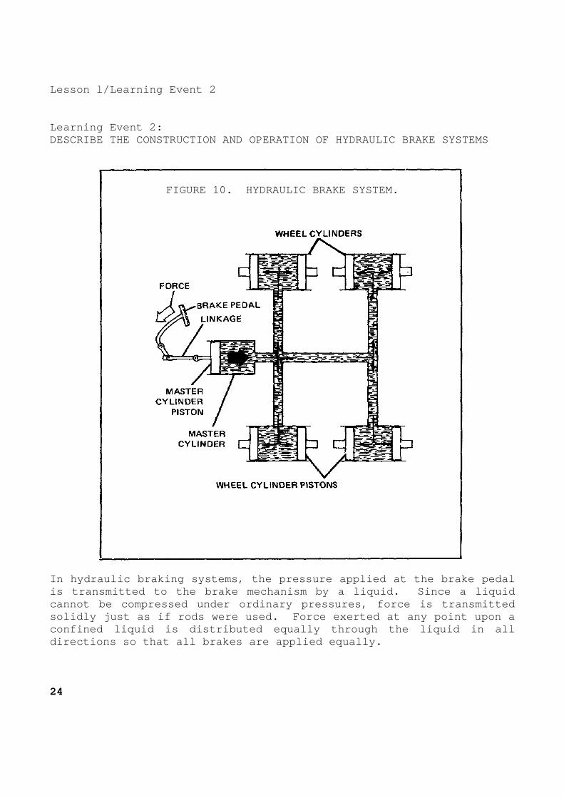
FIGURE 10. HYDRAULIC BRAKE SYSTEM.
In hydraulic braking systems, the pressure applied at the brake pedal is transmitted to the brake mechanism by a liquid. Since a liquid cannot be compressed under ordinary pressures, forc e is transmitted solidly just as if rods were used. Force exerted a t any point upon a confined liquid is distributed equally through the liquid in all directions so that all brakes are applied equally. 24

Lesson 1/Learning Event 2 In a hydraulic brake system, the force is applied t o a piston in a master cylinder. The brake pedal operates the pist on by linkage. Each wheel brake is provided with a cylinder. Insi de the cylinder are opposed pistons which are connected to the brak e shoes. When the brake pedal is pushed down, linkage moves the pisto n within the master cylinder, forcing the brake liquid or fluid from the cylinder. From the master cylinder, the fluid travels through tubing and flexible hose into the four wheel cylinders. The brake fluid enters the wheel cylinders between the opposed pistons. The pressure of the brake fluid on the pi stons causes them to move out. This forces the brake shoes outward a gainst the brake drum. As pressure on the pedal is increased, more hydraulic pressure is built up in the wheel cylinders and more force i s exerted against the ends of the brake shoes. When the pressure on the pedal is released, retract ing (return) springs on the brake shoes pull the shoes away from the drum. This forces the wheel cylinder pistons to their release positions and also forces the brake fluid back through the flexible ho se and tubing to the master cylinder.
25
Lesson 1/Learning Event 2
FIGURE 11. MASTER CYLINDER.
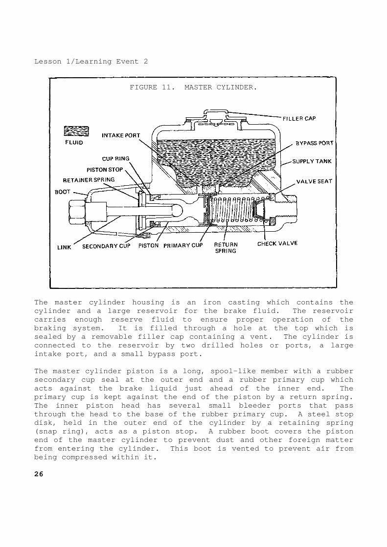
The master cylinder housing is an iron casting whic h contains the cylinder and a large reservoir for the brake fluid. The reservoir carries enough reserve fluid to ensure proper opera tion of the braking system. It is filled through a hole at the top which is sealed by a removable filler cap containing a vent. The cylinder is connected to the reservoir by two drilled holes or ports, a large intake port, and a small bypass port. The master cylinder piston is a long, spool-like me mber with a rubber secondary cup seal at the outer end and a rubber pr imary cup which acts against the brake liquid just ahead of the inn er end. The primary cup is kept against the end of the piston b y a return spring. The inner piston head has several small bleeder por ts that pass through the head to the base of the rubber primary cup. A steel stop disk, held in the outer end of the cylinder by a re taining spring (snap ring), acts as a piston stop. A rubber boot covers the piston end of the master cylinder to prevent dust and othe r foreign matter from entering the cylinder. This boot is vented to prevent air from being compressed within it. 26

Lesson 1/Learning Event 2 In the outlet end of the cylinder is a combination inlet and outlet valve which is held in place by the piston return s pring. This check valve is a little different from most check valves that will let fluid pass through them in one direction only. If enough pressure is applied to this valve, fluid can go either through or around it in either direction. This means it will keep some pre ssure in the brake lines. The check valve consists of a rubber valve cup inside a steel valve case which seats on a rubber valve seat that fits in the end of the cylinder. In some designs, the check valve con sists of a spring-operated outlet valve seated on a valve cage rather than a rubber cup outlet valve. The principle of operation is the sa me. The piston return spring normally holds the valve cage against the rubber valve seat to seal the brake fluid in the brake line.
FIGURE 12. WHEEL CYLINDER.
The wheel cylinder changes hydraulic pressure into mechanical force that pushes the brake shoes against the drum. The wheel cylinder housing is mounted on the brake backing plate. Ins ide the cylinder are two pistons which are moved in opposite directi ons by hydraulic pressure and which, at the same time, push the shoe s against the drum. The piston or piston stems are connected dir ectly to the shoes. Rubber piston cups fit in the
27

Lesson 1/Learning Event 2 cylinder bore against each piston to prevent the es cape of brake liquid. There is a light spring between the cups t o keep them in position against the pistons. The open ends of th e cylinder are fitted with rubber boots to keep out foreign matter . Brake fluid enters the cylinder from the brake line connection between the pistons. At the top of the cylinder, between the p istons, is a bleeder hole and screw through which air is release d when the system is being filled with brake fluid. On some vehicles, a stepped wheel cylinder is used to compensate for the faster rate of wear on the front shoe than on t he rear shoe. This happens because of the self-energizing action. By using a larger piston for the rear shoe, the shoe receives more pressure to offset the self-energizing action of the front shoe . If it is desired that both shoes be independently s elf-energizing, it is necessary to have two wheel cylinders, one for e ach shoe. Each cylinder has a single piston and is mounted on the opposite side of the brake backing plate from the other cylinder. So far, we have discussed the parts needed to make up a hydraulic brake system. Now let's see what happens to these parts when the brakes are applied and released. Let's assume the master cylinder is installed on a vehicle and the hydraulic system is filled with fluid. As the driver pushes down on the brake peda l, linkage moves the piston in the master cylinder. As the piston m oves inward, the primary cup seals off the bypass port (sometimes kn own as the compensating port). With the bypass port closed, the piston traps the f luid ahead of it and creates pressure in the cylinder. This pressur e forces the check valve to open and fluid passes into the brake line. As the piston continues to move, it forces fluid through the line s into the wheel cylinders. The hydraulic pressure causes the wheel cylinder pistons to move outward and force the brake shoes against t he brake drum. As long as pressure is kept on the brake pedal, the sh oes will remain pressed against the drum. When the brake pedal is released, the pressure of t he link or pushrod is removed from the master cylinder piston. The re turn spring pushes the piston back to the released position, reducing the pressure in front of the piston. The check valve slows down th e sudden return of fluid from the wheel cylinders. As the piston move s toward the released position in the cylinder, fluid from the m aster cylinder supply tank flows through the intake port and then through the bleeder holes in the head of the piston. This flui d will bend the lips of the primary cup away from the cylinder wall , and the fluid will flow into the cylinder ahead of the piston. 28

Lesson 1/Learning Event 2 When the pressure drops in the master cylinder, the brake shoe return springs pull the shoes away from the drum. As the shoes are pulled away from the drum, they squeeze the wheel cylinder pistons together. This forces the brake fluid to flow back into the m aster cylinder. The returning fluid forces the check valve to close . The entire check valve is then forced off its seat, and fluid flows into the master cylinder around the outer edges of the valve . When the piston in the master cylinder has returned to its released position against the stop plate, the primary cup uncovers the bypass port and any excess fluid will flow through the bypass port to t he reservoir. This prevents the brakes from "locking up" when the heat of the brakes causes the brake fluid to expand. When the piston return spring pressure is again mor e than the pressure of the returning fluid, the check valve se ats. The valve will keep a slight pressure in the brake lines and wheel cylinders. The brake system is now in position for the next br ake application.
29

Lesson 1/Learning Event 3 Learning Event 3: DESCRIBE INSPECTION PROCEDURES FOR HYDRAULIC BRAKE SYSTEMS INTRODUCTION The hydraulic braking system of the modern high-spe ed automobile must be kept in a high state of repair. Not too many ye ars ago, a small defect in the braking system did not bother too muc h; in fact, it might not even have been noticed. Today, however, improved road conditions and higher vehicle speeds, plus more sen sitive steering and suspension systems, cause a poor braking action to be noticed immediately. The brake system parts must be able t o stand up under high pressures and temperatures and still be able t o work properly if the vehicle is to be operated safely. To properly repair a brake system so it is always in top condition, the mechan ic must be well trained and have a desire to do the best job possib le. BEFORE ROAD-TEST INSPECTION The condition of the hydraulic service brakes of a vehicle can be determined by inspecting the following items: fluid level in the master cylinder, brake pedal free travel, total bra ke pedal travel, feel of brake pedal (hard or spongy), leaks in the hydraulic system, noise during operations, performance, and the amoun t of wear of brake parts. Wear can normally be determined by checking one wheel of each axle. To inspect the fluid level in the master cylinder, first clean away all dirt that may fall into the master cylinder res ervoir. Remove the filler cap and ensure the fluid level is at the level recommended in the maintenance manual pertaining to the vehicle being serviced. The level of fluid is determined by measuring the d istance from the top of the filler hole to the level of fluid in the reservoir. If the fluid level is low, refer to the vehicle's l ubrication order for the recommended type of brake fluid and add flu id as needed. Since the end of 1982, all military vehicles use si licone brake fluid. Silicone fluid does not absorb water, provi des good corrosion protection, and has good lubrication qualities. Th e fluid is also compatible with the rubber components of the brake system. Check the master cylinder supply tank reservoir ven t to make sure that it is not plugged. On some vehicles, a small hole drilled in the filler cap vents the supply tank. On other veh icles, the supply tank is vented through a line and fitting connected to the top of the master cylinder supply tank. A plugged vent can be easily cleared with compressed air. 30

Lesson 1/Learning Event 3 Measure the brake pedal free travel and compare the measurement with the specifications given in the vehicle's maintenan ce manual. Brake pedal free travel is the amount that the brake peda l can be moved without moving the master cylinder piston. If the pedal has too much free travel, it will have to be pushed farther befo re the brakes apply. If there is not enough free travel, it may prevent the brakes from releasing. To check the total travel of the brake pedal, push the brake pedal down as far as you can. You should not be able to push the brake pedal on most trucks any closer to the floorboard t han 2 inches.
- If there is too much pedal travel, but the pedal feels firm, the problem is probably caused by normal wear of th e brake lining. When the lining is not worn too badly, an adjustment of the brake shoes will correct excessive pedal tra vel. Unfortunately, the only way to determine the exact amount of the brake lining wear on most vehicles is to remove the wheels and brake drums.
- If the pedal travel is too great and the pedal fe els spongy,
there is probably some air in the hydraulic system. Air trapped in the hydraulic system can be compressed a nd does not permit pressure applied to the pedal to be applied solidly to the brakes. Methods of correcting these problems a re covered later in this lesson.
Inspect the hydraulic system for leaks. Large leak s can be detected while checking the pedal travel. This is done by h olding a steady pressure on the brake pedal for a few moments. If the pedal continues to move down, there is a large leak. Sma ll leaks cannot be detected this way as they cause the pedal to fall a way too slowly to be noticed. Look the entire hydraulic system over for any visib le indications of leakage. Inspect the master cylinder, especially a round the rubber boot, for external fluid leaks. Inspect all steel lines (tubes) for leakage, loose fittings, wear, dents, corrosion, an d missing retaining clips. Inspect the flexible hoses for le akage, cuts, cracks, twists, and evidence of rubbing against oth er parts. Inspect the area at the lower edge of the backing plate for the presence of any brake fluid or grease. Leakage of either brake fluid or grease at the wheels is an indication of brake problems.
31
Lesson l/Learning Event 3 ROAD-TEST INSPECTION Road-test the vehicle and check the operation of th e brakes by stopping several times while traveling on a smooth road. Check for squeaking or grinding sounds when the brakes are ap plied, an excessive amount of pressure required on the brake pedal to stop the vehicle, and the vehicle pulling to one side when t he brakes are applied (uneven braking). If the brakes make a squeaking or grinding sound, s ome of the more common causes are:
- Glazed or worn lining. - Lining loose on the brake shoes. - Dirt embedded in the lining. - Improper adjustment. - Brake fluid or grease on the lining. - Scored brake drums or rotors.
NOTE
The wheel and brake drum will have to be removed from the noisy brake and the brake parts inspected to determine the exact cause of the noise.
When excessive pressure must be applied to the brak e pedal to stop the vehicle, any one or more of the following items may be the cause:
- Glazed or worn brake lining. - Improperly adjusted brake shoes. - Dirt in the brake drums. - Grease or brake fluid on the lining. - Faulty master cylinder. - Binding pedal linkage. - Restricted brake line.
AFTER ROAD-TEST INSPECTION If such things as pulling to one side or poor braki ng action are noted during a road test, an after road-test inspec tion is done. 32

Lesson 1/Learning Event 3 Many faults occur in the brake system that can caus e the vehicle to pull to one side. However, all these faults have o ne thing in common: they affect the brake in one wheel causing that wheel to hold either more or less than the other wheels. If the affected wheel holds more, the vehicle will pull toward the affect ed wheel; if it holds less, the vehicle pulls away from the affecte d wheel. The most common faults that cause the brakes to hold unevenl y are unequal brake adjustment, grease or brake fluid on the lini ng, dirt in the brake drum, brake drum or rotor scored or rough, di fferent kinds of brake linings on opposite wheels, primary and secon dary brake shoes reversed in one wheel (on some vehicles), glazed or worn lining, restricted brake line, weak brake shoe return sprin gs, or sticking pistons in a wheel or caliper cylinder. If the inspection indicates that the wheel brakes a re at fault, you must determine the condition of the brake parts in the wheel brakes. Do this by removing one wheel and brake drum from e ach axle assembly and inspecting the brake parts in these wheels. It is reasonable to assume that the condition of both brake assemblies on one axle will be about the same. Inspect the condition of the br ake drum, brake lining, brake shoe anchor, hold-down springs, retra cting (return) springs, brake shoe adjusting mechanism, and wheel cylinder.
33

Lesson 1/Learning Event 3
This page intentionally left blank. 34
Lesson 1 PRACTICE EXERCISE 1. What is used to slow or stop a vehicle? a. Friction b. Momentum c. Inertia 2. At what point is maximum retardation (slowing do wn) of a vehicle
reached? a. When brakes are first applied b. Just before the brakes lock c. When the brakes lock 3. What is the advantage of self-energizing brakes? a. Smoother brake action b. Increased pressure on the braking surfaces c. Decreases tendency to skid on sudden stops 4. What is the purpose of the light spring between the cups of a
wheel cylinder? a. Return the piston to the released position b. Slow down the application of the brakes c. Keep the cups in position against the pistons 5. Which of the following is an advantage of disk b rakes over drum
brakes? a. Disk brakes fade less b. Disk brakes are self-energizing c. Disk brakes are less expensive
35

Lesson 1 ANSWERS TO PRACTICE EXERCISE 1. a (page 2) 2. b (page 4) 3. b (page 16) 4. c (page 28) 5. a (page 19) 36

Lesson 2/Learning Event 1
LESSON 2 AIR-HYDRAULIC BRAKE SYSTEMS
TASK Describe the principles, construction, and operatio n of air-hydraulic brake systems. CONDITIONS Given information on the purpose, components, opera tion, and inspection of air-hydraulic brake systems. STANDARDS Answer 70 percent of the multiple-choice test items covering fundamentals of air-hydraulic brake systems. REFERENCES TM 9-8000 Learning Event 1: DESCRIBE THE COMPONENTS OF THE AIR-HYDRAULIC BRAKE SYSTEM INTRODUCTION Most passenger cars and light-duty trucks have the straight hydraulic brake system which uses only the energy that is app lied to the brake foot pedal. This type brake does a good job on lig ht-duty vehicles, but medium- and heavy-duty vehicles require a bette r braking system. The Army's 2 1/2-ton and some 5-ton tactical design trucks have air-hydraulic brakes. Air-hydraulic brakes have hydrau lic and compressed air systems. The hydraulic systems of straight hyd raulic brakes and air-hydraulic brakes are about the same. The compr essed air system supplies air pressure to boost the hydraulic pressu re to the wheel cylinders above the amount supplied from the master cylinder.
37
Lesson 2/Learning Event 1 TYPICAL BRAKE SYSTEM
FIGURE 13. AIR-HYDRAULIC BRAKE SYSTEM.
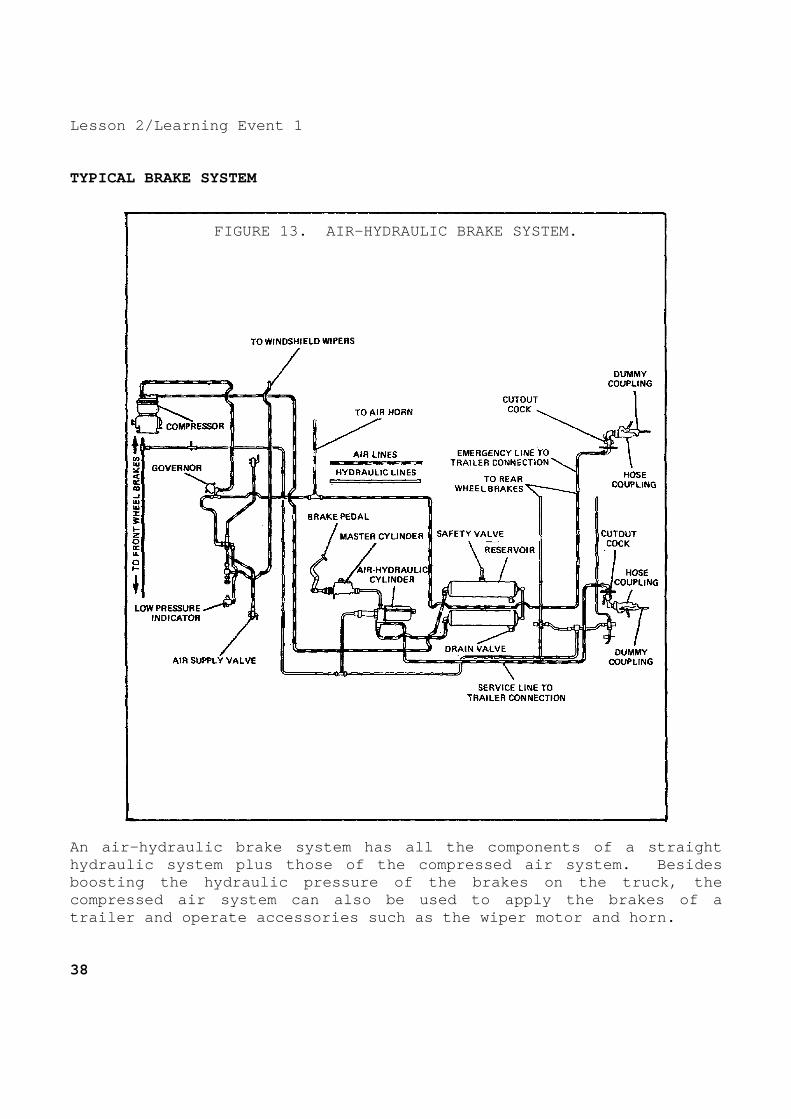
An air-hydraulic brake system has all the component s of a straight hydraulic system plus those of the compressed air s ystem. Besides boosting the hydraulic pressure of the brakes on th e truck, the compressed air system can also be used to apply the brakes of a trailer and operate accessories such as the wiper m otor and horn. 38

Lesson 2/Learning Event 1 MASTER CYLINDER The master cylinder used with air-hydraulic brakes is like the one described in the lesson on hydraulic brakes. In st raight hydraulic brake systems, the master cylinder receives the ini tial mechanical force from the pedal linkage, changes it to hydraul ic pressure, and sends the brake fluid under pressure directly to th e wheel cylinders. In air-hydraulic brakes, the master cylinder sends brake fluid under pressure to an air-hydraulic cylinder before it goe s to the wheel cylinders. On all military designed vehicles, the master cylinder has a vent fitting at the top of the reservoir for connecting a vent line to the vent system of the vehicle. This preve nts water from entering the master cylinder through the vent durin g fording operations. The special drilled bolt and fitting i nstalled in the filler cap of the master cylinder serves this purpo se. AIR-HYDRAULIC CYLINDER The air-hydraulic cylinder is put into operation by the hydraulic pressure from the master cylinder. It uses compres sed air to boost the hydraulic pressure from the master cylinder. T he Army uses more than one model of air-hydraulic cylinders; all mode ls contain the same major units and operate on the same principles . They are made up of three major units in one assembly. The units are the control unit, power cylinder, and slave cylinder. The unit s of the M809-series vehicles consist of an air valve, air cylind er, hydraulic cylinder, and piston. The control unit contains a control valve (relay) p iston, which is hydraulically operated by brake fluid from the mast er cylinder, and a diaphragm or compensator assembly, which is operate d by pressure differences between brake fluid and air and spring pressure. A return spring holds the hydraulic relay piston and diaphragm assembly in the released position when there is no hydraulic pressure. Two air poppet valves, assembled on one stem, control t he air pressure flowing into and out of the power cylinder. The po ppet valves are normally held in the released position by the poppe t return spring.
39

Lesson 2/Learning Event 1 The power cylinder consists of a cylinder, piston, piston rod, and piston return spring. Air pressure admitted at the head end of the cylinder compresses the piston return spring extend ing the piston rod. When the air pressure is released, the spring retracts the rod. Air in the rod end of the cylinder can pass freely in and out of the cylinder through a breather air line that is attach ed to the air intake system of the vehicle. A lip-type piston se al prevents air pressure from leaking between the piston and cylind er wall. The slave cylinder is a hydraulic cylinder containi ng a piston and piston cup. Some cylinders contain a check valve a ssembly, at the hydraulic outlet, for maintaining a slight amount o f pressure (residual) in the hydraulic lines and wheel cylinde rs. The piston and piston cup are hollow and contain a check valve that allows brake fluid to pass through freely when the power cylinde r is retracted. When the power cylinder extends, the check valve bl ocks the opening through the center of the slave cylinder piston. 40
Lesson 2/Learning Event 1 AIR COMPRESSOR
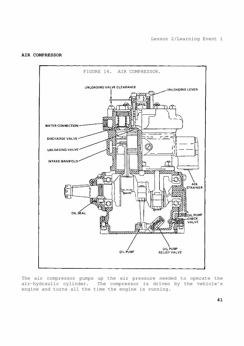
FIGURE 14. AIR COMPRESSOR.
The air compressor pumps up the air pressure needed to operate the air-hydraulic cylinder. The compressor is driven b y the vehicle's engine and turns all the time the engine is running .
41

Lesson 2/Learning Event 1 It is generally belt driven, but on some 5-ton truc ks it is gear driven. The air compressor used on the M809-series vehicle is of the single-action, piston-type, and cooling and lubricating ar e accomplished by the engine's respective cooling and lubricating sys tems. The compressor is mounted to the left side of the engin e. An unloader valve in the cylinder head vents compressed air whe n pressure exceeds the predetermined level. On some compressor models, the lubricating oil is c arried from the engine main oil gallery to the compressor by a flex ible line. Oil leaking past the compressor bearings drains into th e compressor mounting base. A return line connected to the moun ting base returns the oil to the engine crankcase. On other compressor models, lubricating oil is carr ied to and from the air compressor through passages in the compress or mounting base. The compressor mounting base oil passages align wit h oil passages in the engine crankcase and the compressor. The compression of air in the compressor creates so much heat that the compressor must be cooled. Some compressors ar e air cooled while others are water cooled from the engine's cooling s ystem. Air-cooled compressors have cooling fins around the cylinders and the cylinder head. Water-cooled compressors have water jackets either in the cylinder head or around the cylinders. A water inl et line and a water outlet line connect the compressor water jack et to the engine cooling system. The compressor has air-check valves, one intake and one exhaust valve for each cylinder. The valves are held closed by l ight spring tension. In each cylinder the intake valve is open ed by the suction created by the cylinder piston on its downward (int ake) stroke. The exhaust valve is opened by air, compressed in the c ylinder on the piston's upward (exhaust) stroke. An air strainer is mounted over the air compressor air intake port. The air strain er inlet is connected to the engine air intake system. During the intake stroke of either compressor cylin der, air is drawn through the air strainer and intake valve and into the cylinder. On the exhaust stroke, the air compressed in the cylin der holds the intake valve tightly closed and opens the exhaust v alve. The compressed air then flows through the exhaust valve into the compressed air system through an air discharge line connected to the compressor. 42

Lesson 2/Learning Event 1 An unloading mechanism on the cylinder head unloads compressor compression whenever the air pressure reaches a pre determined maximum. The unloader mechanism generally has a di aphragm connected to linkage, so that when air pressure is applied at one side of the diaphragm, the diaphragm is moved to hold either th e unloader valves or the intake valves open. At this time, the compr essor will continue to run with the engine but will not compre ss air. When the air pressure drops to a certain predetermined amoun t, the pressure is released from the diaphragm, permitting the intake or unloader valves to close and the compressor pumps up the pressure a gain. AIR GOVERNOR The operation of the unloader mechanism is controll ed by the air governor. Many different designs of governors are used, but they all serve the same purpose and operate on the same basi c principles. Primarily, any air governor is a valve held closed by spring tension. Air pressure from the compressor and air reservoir is applied to a diaphragm, piston, or a similar device that opposes the spring tension in an attempt to open the valve. When the air pressure reaches a desired maximum of about 110 to 120 PSI, air pressure overcomes the spring tension and the governor valve opens. Air pressure flows through the open valve to the unload er mechanism opening the unloader valves. When the air pressure drops to a desired minimum, spring tension on the governor val ve overcomes the air pressure closing the valve. This releases the air pressure to the unloader allowing the unloader valves to close. The air governor is mounted on the engine side of t he cowl (firewall). At least two air lines must be connect ed to a governor: one pressure line from the air supply and one line to the unloader on the compressor. A third line, for the pressure exh aust may be connected between the governor and the vehicle vent system. The governor contains a filter to strain the air that p asses through it. Most governors have an external adjustment that all ows the mechanic to change the tension on the spring holding the air valve closed, which will in turn change the amount of air pressur e required to open the governor.
43
Lesson 2/Learning Event 1 AIR RESERVOIR Two round steel tanks are used on each truck to hol d a supply of compressed air. The tanks are large enough to prov ide enough air under pressure for several brake applications after the engine has stopped running. The reservoirs also provide a pla ce to trap condensed oil and water vapors. The air, which is heated during compression, is cooled in the tanks causing any vap ors in the air to condense. A drain cock is provided in the bottom o f each reservoir to drain trapped condensation. SAFETY VALVE A relief valve, known as the safety valve, is insta lled on one of the reservoirs. It is used to prevent air pressure in the system from building up above a safe operating pressure if the governor or unloader mechanism should fail. The valve is held closed by spring pressure and opened by air pressure. When the air pressure in the reservoir exceeds 150 PSI, the valve opens exhausti ng the excess pressure. WARNING SIGNAL BUZZER An electrically operated buzzer is located under th e dash panel to warn the vehicle operator if the air pressure falls below a safe operating level. The buzzer sounds when an air-ope rated switch closes to connect an electrical circuit between the buzzer and the vehicle batteries. The switch is generally mounted under the dash panel near the buzzer and is connected to an air li ne from the air reservoir. Air pressure on a piston in the switch tends to open the switch contacts, while spring pressure tends to clo se the switch contacts. When the air pressure falls below 60 PSI , spring pressure closes the switch and the buzzer sounds. PRESSURE GAGE An air pressure gage is located on the dash panel t o show the amount of pressure in the air system. The gage is made to read pressures from 0 to 120 PSI. HAND CONTROL VALVE Some trucks have a hand control valve mounted on th e steering column for individual control of the brakes on towed vehic les. Two air lines are connected to the valve: One is a supply l ine from the truck's air reservoir, and the other is a control l ine that is attached to the brakes of the trailer. A third thr eaded air opening in the valve is an air exhaust outlet which is left open. 44
Lesson 2/Learning Event 1 The hand control valve assembly has an inlet and an exhaust valve mounted on one stem. The valve is normally held in the exhaust position by the intake and exhaust valve spring. O ne type of hand control valve has a movable exhaust tube that is pu shed upward by an exhaust tube spring and downward by a cam plate spr ing. A hand lever on the control valve is used to rotate a cam changi ng the tension on the cam plate spring. With the hand lever in the released position, the e xhaust tube spring holds the exhaust tube up. Any air pressure in the trailer brake control line is exhausted through the exhaust tube and outlet on the control valve. Pulling the hand lever to the appli ed position increases the cam plate spring tension on top of th e exhaust tube. This moves the exhaust tube down, first contacting the exhaust valve and blocking the air exhaust passage through the tu be. Then it moves the air exhaust and inlet valve assembly down, push ing the air inlet valve off its seat. Air supply pressure flows past the open inlet valve into the control line to apply the trailer br akes. The control air pressure also pushes upward on the exhaust tube tending to lift it and close the inlet valve. When the pressures a bove and below the tube are equal, the inlet valve closes. By changin g the position of the hand lever, the amount of spring tension pushin g the exhaust tube down will change, and the driver can regulate the a mount of control line pressure. TRAILER COUPLING HOSES AND CONNECTORS Two air outlets are provided at the rear of the tru ck for connecting its brake system to the trailer brakes. One outlet contains a tag with the word "EMERGENCY" printed on it; the second outlet has a tag with the label "SERVICE." Two air line connections on the trailer also have emergency and service tags. When connect ing the two brake systems together, the emergency line on the truck m ust be connected to the emergency line on the trailer. Likewise, th e service lines must be connected together. The service line conne cts the air control line of the truck to the control line of th e trailer to control the normal application of the brakes. The emergency line connects the air supply of the truck to the emergen cy relay valve of the trailer. If the emergency line should break or be disconnected, the trailer brakes automatically apply. An air shutoff cock is located at each trailer conn ection outlet on the truck. The cocks must be turned off to prevent the loss of air when the truck brake system is not connected to a t railer brake system.
45

Lesson 2/Learning Event 1 A quick disconnect air hose coupling assembly is in stalled on the air line connections of both the trailer and the truck. The coupling assembly contains a lockpin and a replaceable body washer. When the trailer connections are not being used, a dummy cou pling is installed on the air hose coupling assemblies to keep dirt an d water out of the coupling. Flexible high-pressure hoses are used to connect th e air coupling assemblies on the truck and trailer together. Hose coupling assemblies that interlock with the couplings on the vehicles are installed on the ends of the hoses. EMERGENCY RELAY VALVE Trailers that are equipped with their own air reser voir have an emergency relay valve. This valve is mounted near the trailer's air reservoir and air-over-hydraulic cylinder. It cons ists of a relay section and an emergency section which work togethe r to control the action of the air-over-hydraulic cylinder and wheel brakes. In normal operation, the emergency relay valve serv es as a relay station. It receives air pressure control signals from the truck brake system and relays them to the trailer brakes. Instead of using air pressure directly from the truck to apply the t railer brakes, the valve uses air from the trailer air reservoir. Whe n the brakes are released, the applied pressure is released through an exhaust port on the emergency relay valve. The relaying action of the valve speeds up the action of the brakes. In addition to the above, the emergency relay valve controls the flow of air from the truck reservoir into the trailer re servoir. Since the trailer does not have an air compressor, it mus t depend on the truck's compressed air system to keep its air reser voir pumped up. The emergency relay valve also directs air pressure to the air-over-hydraulic cylinder to automatically apply the trail er brakes if the trailer breaks away from the truck or if there is a serious leak in the emergency line. The emergency relay valve has two main body section s separated by a relay valve diaphragm. It contains three internal valves and a number of air passages. Threaded openings are prov ided for connections to the emergency air line, service air line, air reservoir, and air-over-hydraulic cylinder. The ex haust opening is also threaded. A drain plug is usually provided in the bottom of the assembly for draining condensation. 46

Lesson 2/Learning Event 1 AIR-OVER-HYDRAULIC CYLINDER The air-over-hydraulic cylinder assembly of a trail er consists of a brake air chamber and hydraulic master cylinder. T he master cylinder is like any typical hydraulic brake master cylinder and is used to force fluid under pressure to the wheel cylinders i n the wheel brakes. The brake air chamber changes air pressure into mechanical motion to operate the master cylinder. On tandem-a xle trailers an air-over-hydraulic cylinder may be used on each axl e. The brake air chamber contains a diaphragm secured between the outer edges of the body and cover. The diaphragm is airt ight and divides the chamber into pressure and non-pressure sides. The pressure side of the chamber has a threaded opening for connectin g the brake apply air line. The nonpressure side is vented to the ou tside air. A compression spring in the nonpressure side holds a pushrod against the diaphragm, and returns both the diaphragm and p ushrod to the pressure side of the chamber. One end of the pushr od extends from the nonpressure side of the chamber. The master cylinder is mounted on the brake air cha mber so that the pushrod aligns with the master cylinder piston. Wh en compressed air enters the pressure side of the brake chamber, the diaphragm moves toward the nonpressure side. This extends the push rod, moving the master cylinder piston, and forcing brake fluid to the wheel cylinders to apply the brakes. When the compressed air in the chamber is released, the compression spring returns the pushrod and diaphragm to the pressure side of the chamber allow ing the brakes to release.
47

Lesson 2/Learning Event 2 Learning Event 2: DESCRIBE THE OPERATION OF THE AIR-HYDRAULIC BRAKE S YSTEM 5-TON, 6X6 TRUCKS Now that you are familiar with the components that make up air-hydraulic brake systems, let's see how they work to gether to stop a vehicle. First, let's consider a truck that is not connected to a trailer. We will use the brake system of the 5-ton , 6x6 truck for our discussion.
FIGURE 15. AIR-HYDRAULIC CYLINDER.
48
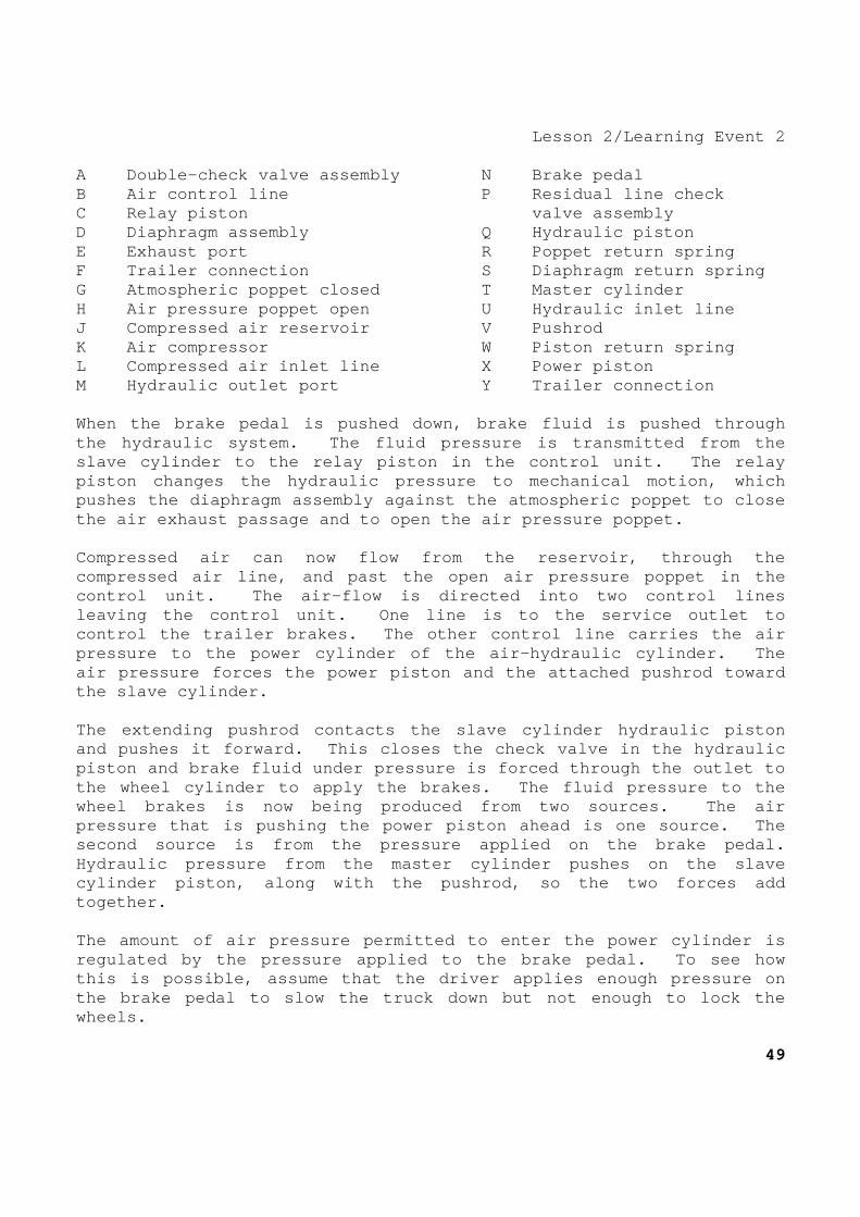
Lesson 2/Learning Event 2 A Double-check valve assembly N Brake pedal B Air control line P Residual line check C Relay piston valve assembly D Diaphragm assembly Q Hydraulic piston E Exhaust port R Poppet return spring F Trailer connection S Diaphragm return spring G Atmospheric poppet closed T Master cylinder H Air pressure poppet open U Hydraulic inlet line J Compressed air reservoir V Pushrod K Air compressor W Piston return spring L Compressed air inlet line X Power piston M Hydraulic outlet port Y Trailer connection When the brake pedal is pushed down, brake fluid is pushed through the hydraulic system. The fluid pressure is transm itted from the slave cylinder to the relay piston in the control u nit. The relay piston changes the hydraulic pressure to mechanical motion, which pushes the diaphragm assembly against the atmospher ic poppet to close the air exhaust passage and to open the air pressur e poppet. Compressed air can now flow from the reservoir, thr ough the compressed air line, and past the open air pressure poppet in the control unit. The air-flow is directed into two co ntrol lines leaving the control unit. One line is to the servi ce outlet to control the trailer brakes. The other control line carries the air pressure to the power cylinder of the air-hydraulic cylinder. The air pressure forces the power piston and the attach ed pushrod toward the slave cylinder. The extending pushrod contacts the slave cylinder h ydraulic piston and pushes it forward. This closes the check valve in the hydraulic piston and brake fluid under pressure is forced thr ough the outlet to the wheel cylinder to apply the brakes. The fluid pressure to the wheel brakes is now being produced from two sources . The air pressure that is pushing the power piston ahead is one source. The second source is from the pressure applied on the b rake pedal. Hydraulic pressure from the master cylinder pushes on the slave cylinder piston, along with the pushrod, so the two forces add together. The amount of air pressure permitted to enter the p ower cylinder is regulated by the pressure applied to the brake peda l. To see how this is possible, assume that the driver applies en ough pressure on the brake pedal to slow the truck down but not enou gh to lock the wheels.
49

Lesson 2/Learning Event 2 The air pressure that is permitted to enter the con trol unit pushes on the diaphragm assembly in an attempt to close th e air inlet poppet valve. Recall that hydraulic pressure from the mas ter cylinder on the relay piston opened the air inlet poppet. Ther efore, the air pressure against the diaphragm assembly is opposing the hydraulic pressure on the relay piston. When the air pressur e reaches a point where it overcomes the hydraulic pressure, the diap hragm assembly and relay valve move slightly allowing the air inlet po ppet to close shutting off incoming air. But the atmospheric pop pet remains closed so the controlled air pressure is trapped in the po wer cylinder. This is known as the "holding" or "lap" position. The air-hydraulic cylinder will remain in the holdi ng position maintaining an unchanging amount of controlled air pressure as long as the same amount of foot pressure is applied to t he brake pedal. The amount of brake application is determined by th e amount of controlled air pressure trapped in the power cylind er. If more foot pressure is applied on the brake pedal, more hydrau lic pressure is applied on the relay piston. This opens the air in let poppet and the controlled air pressure increases until it is great enough to overcome the increased hydraulic pressure and move the relay piston back allowing the air inlet poppet to close. When the brake pedal is released, hydraulic pressur e on the relay piston is removed. This allows the diaphragm retur n spring to return the diaphragm assembly to the released position ope ning the atmospheric poppet. The control pressure is releas ed to the outside air by passing through the drilled center of the di aphragm assembly and the exhaust port. The piston return spring ret urns the power piston, pushrod, and hydraulic piston to the releas ed position. As the hydraulic piston nears the released position, t he check valve in the center of the piston opens. The residual check valve assembly in the outlet of the slave cylinder maintains a slight pressure in the lines and wheel cylinders, just as the master cylinder check valve does in straight hy draulic brakes. To operate properly, the air-hydraulic cylinder mus t have a supply of compressed air. But if the air supply should fail, the vehicle brakes will still be applied when the brake pedal i s pressed. Brake fluid from the master cylinder will flow through th e check valve in the center of the slave cylinder hydraulic piston t o the wheel brakes. There will be no boost from the air-power cylinder, but the vehicle could be operated under emergency condition s. 50

Lesson 2/Learning Event 2 Now let's discuss the complete compressed air syste m of the 5-ton, 6x6 truck. The truck has service and emergency tra iler couplings at the front as well as at the rear. If a truck must be towed, the trailer couplings at the front can be connected to the rear trailer couplings of the towing truck. With the two brake systems connected in this manner, the brakes of both trucks can be co ntrolled from the towing truck. Three double-check valves direct the flow of controlled air pressure. One double-check valve is located at the control li ne connection of the air-hydraulic cylinder. The center connection of the valve is connected to the power cylinder. The control line from the air-hydraulic cylinder control valve is connected to an end connection of the double-check valve. The control or service lin e from the front of the truck is attached to the remaining end conne ction of the double-check valve. When the control unit of the air-hydraulic cylinder sends air pressure to the double-check valve, the air pressur e moves a sliding piston in the valve closing the service line passag e to the front of the truck. The air can move freely from the contro l unit, through the double-check valve, into the power cylinder to apply the brakes. When the truck is being towed and the brakes are ap plied, the double-check valve prevents the escape of controlled air f rom the towing truck. Brake air controlled pressure from the tow truck flows through the service line to the double-check valve. The controlled air moves the sliding piston closing the passage to the air-hydraulic control unit. Controlled air pressure now flows fr eely from the tow truck, through the double-check valve, and into the power cylinder. The two remaining double-check valves direct the co ntrolled air flowing to the trailer service coupling at the rear of the truck. They are connected so that controlled pressure furn ished from one control unit cannot flow to another control unit. This must be done to prevent the escape of controlled pressure. For instance, if controlled pressure from the air-hydraulic cylinder is allowed to flow through the control lines to the hand control valve, the pressure will be released through the open-hand con trol exhaust valve. The double-check valves used on the 5-ton truck mak e it possible for the brakes of a towed vehicle to be applied by usin g either the brake pedal or the hand control of the towing truck. Whe n the brake pedal is pushed down, the brakes of both the towing and t he towed vehicle are applied. When the hand control valve is applie d, the double-check valves direct the controlled air so only the brakes of the towed vehicle are applied.
51

Lesson 2/Learning Event 2 2 1/2-TON-SERIES TRUCKS The principles of operation of the air-hydraulic br akes of the 5-ton, 6x6 trucks can be applied to the air-hydraulic brak es of the 2 1/2-ton-series trucks. However, there is enough differ ence in the design of the two brake systems so that a short discussion on the 2 1/2-ton truck brakes is needed. The air-hydraulic cylinder of a 2 1/2-ton truck loo ks different from that of a 5-ton truck, but the operation is about t he same. Brake fluid applied pressure from the master cylinder is transmitted to the slave cylinder and the fluid passage at one end of the hydraulic control valve piston. The control valve piston the n pushes on the slave cylinder compensator piston moving it to clos e the air exhaust valve and open the air inlet valve. Air pressure f rom the reservoir flows through the air inlet opening and out one con trol line to the power cylinder and a second control line to the tra iler service coupling. Air pressure on the compensator piston and hydrauli c pressure on the control valve piston oppose each other to regulate the controlled air pressure. When the brake pedal is released, hydrau lic pressure is removed from the control valve piston and the compe nsator piston spring returns the compensator piston and control v alve to the released position. This allows the air inlet valve to close and opens the air exhaust valve. Controlled pressure i s exhausted through the hollow compensator piston and out the a ir breather port. The power cylinder and hydraulic slave cylinder wor k just like the power and slave cylinders on the 5-ton truck with t wo exceptions. The hydraulic piston is returned by inner and outer slave cylinder piston springs. There is no residual line pressure check valve in the outlet of the 2 1/2-ton truck's slave cylinder like on the 5-ton truck. The 2 1/2-ton M35-series truck has the resi dual line pressure check valve in the outlet of the master cylinder. The M35-series cargo trucks do not have a hand cont rol valve or trailer couplings at the front of the truck as the 5-ton truck does. However, they do have service and emergency trailer couplings at the rear of the truck. The 2 1/2-ton tractor trucks ha ve a hand control valve so the trailer brakes can be operated separat ely. 52

Lesson 2/Learning Event 2 TRAILERS Several different applications of air-over-hydrauli c brake systems are used on trailers, but they can be broken down i nto two general types--brake systems with automatic breakaway prote ction, and brake systems that do not have breakaway protection. Trailer air-over-hydraulic brake systems that do no t have breakaway protection have only one air hose coupling which mu st be connected to the service trailer coupling on the truck. When ei ther the brake foot pedal or the hand control valve on the truck i s applied, brake controlled air pressure flows through the service a ir line to the trailer. On the trailer, the air line carries the controlled air to an air filter and then to the brake air chamber. The brak e air chamber changes the air pressure to the mechanical motion n eeded to work the hydraulic master cylinder. As the air chamber push rod moves the master cylinder piston, brake fluid is forced into the wheel cylinders to apply the wheel brakes. When the brakes are released by the driver, air pre ssure in the trailer brake air chamber flows back to the truck t hrough the service line and is exhausted through the hand control valv e or the air-hydraulic cylinder control unit. Trailers with automatic breakaway protection have a n emergency air hose coupling, emergency relay valve, and an air re servoir plus all the parts used on trailer brake systems without bre akaway protection. The action of this brake system is controlled by th e emergency relay valve. Let's discuss its operation. With the air hose couplings connected to the truck and the air shutoff cocks open, compressed air from the truck r eservoirs flows through the emergency line to the supply air inlet opening of the emergency relay valve. The air flows through the c heck valve in the center of the emergency valve diaphragm, through th e air supply passage, and out the reservoir line opening to the trailer reservoir. The airflow continues until the pressure in the tra iler reservoir is equal to the pressure in the truck reservoir. Unde r these conditions the air pressure above and below the emergency diap hragm is equal, so the emergency diaphragm spring holds the diaphragm in the raised position.
53
Lesson 2/Learning Event 2 When the truck driver applies the brakes, controlle d air from the truck flows through the service line to the control line inlet at the top of the emergency relay valve. An internal pass age carries the controlled pressure to the cavity above the relay v alve diaphragm. Because this cavity is small, the controlled air fi lls it quickly and moves the diaphragm and relay valve plunger down, c ompressing the relay valve diaphragm spring. The valve plunger cl oses the exhaust valve and then compresses the valve spring, opening the air inlet valve. Compressed air now flows from the trailer r eservoir through the reservoir line opening, past the open air inlet valve, and out the outlet opening to the brake chamber. The brake chamber rod extends working the master cylinder and applying th e brakes. When the driver releases the brakes, controlled lin e pressure is released from the top of the relay valve diaphragm and the relay valve plunger. The diaphragm spring pushes the rel ay valve plunger up, opening the exhaust valve and permitting the va lve spring to close the air inlet valve. Brake applied air press ure in the brake chamber is released to the open air by passing thro ugh the open center of the relay valve plunger to a cavity that is connected to the exhaust port of the emergency relay valve. The emergency relay valve will maintain an air appl ied pressure in the brake chamber that corresponds with the air con trolled pressure from the truck. This is known as the balanced or h olding position and occurs when brake control pressure from the tru ck pushing down on the relay diaphragm is equal to the upward pressure on the diaphragm. Upward pressure is exerted by the diaphragm spring and brake applied air pressure. The applied pressure is admitted to the bottom side of the relay diaphragm through an internal passage fro m the air applied passage. When pressures on both sides of the diaph ragm are equal, the diaphragm is held in the mid position so that b oth the air inlet valve and the air exhaust valve are closed, which m aintains a definite amount of brake applied air pressure. If controlled pressure is increased, it pushes the valve plunger down opening the air inlet valve to increase applied pressure. If c ontrolled pressure is decreased, the valve plunger moves up exhausting some applied pressure. 54

Lesson 2/Learning Event 2 Now let's see how the emergency relay valve provide s automatic breakaway protection. Since the emergency air line is connected to the air supply inlet opening, air pressure from the truck reservoir is present on the bottom side of the emergency valv e diaphragm. Air pressure from the trailer reservoir is present on t he top side of the emergency valve diaphragm from the air supply passa ge and the reservoir line inlet opening. Air can pass from th e truck reservoir to the trailer reservoir through the one-way check valve in the emergency valve diaphragm, so that during normal op eration the air pressure above and below the diaphragm is equal. A t this time the emergency valve diaphragm release spring will hold the diaphragm in the raised position. Assume that there is a loss of air pressure in the emergency line. This could be caused by the trailer breaking away f rom the truck and breaking the line or by a leaking or disconnected e mergency air hose coupling. This removes the air pressure on the bot tom side of the emergency valve diaphragm. Air pressure from the t railer reservoir on top of the diaphragm pushes the diaphragm down c ompressing the diaphragm release spring. The downward movement is transferred to the relay valve plunger, closing the air exhaust va lve and opening the air inlet valve allowing compressed air to flow from the reservoir to the brake chamber locking the brakes. The relay valve plunger will remain in the applied position as long as there is air pressure in the trailer reservoir o r until the service line is reconnected to a truck. To release the trailer brakes without connecting the trailer to a truck, t he drain cock in the bottom of the reservoir should be opened to all ow all the compressed air in the system to escape.
55

Lesson 2/Learning Event 3 Learning Event 3: DESCRIBE INSPECTION PROCEDURES FOR THE AIR-HYDRAULIC BRAKE SYSTEM INTRODUCTION Maintenance of air-hydraulic brake systems is much the same as that for straight hydraulic brake systems. The major di fference between the two is that the air-hydraulic system contains c omponents for compressing air and applying air pressure to the hy draulic system. As with any other automotive system, a well-organiz ed sequence of events must take place to properly maintain air-hyd raulic braking systems. The steps to take include a preroad test inspection, a road test, and an after-road test inspection to determin e if there are any troubles, a troubleshooting step to determine the c ause of any failure, and then the service and repair required t o correct the failures. The maintenance procedures between 2 1/2- and 5-ton military vehicle braking systems will not vary too much. Therefore, throughout this lesson, general maintenance practices will pertain to all air-hydraulic brake systems unless specific exceptions are discussed. BEFORE ROAD-TEST INSPECTION Many times a good visual inspection is all that is needed to locate a brake failure. However, to ensure that all parts o f a braking system are working properly, a complete inspection should be made. The best place to start a visual inspection is at t he brake pedal. Check to ensure the pedal does not bind and that it operates the linkage correctly. When the pedal is released, spr ing tension should return it to its released stop position. Check to ensure there is enough free travel in the pedal movement to allow t he brakes to completely release when the pedal is released. Che ck for wear on the pedal bushing. The pedal should move freely but no t have any sideways motion. Check the pedal travel for spongi ness which would indicate air in the hydraulic system. Inspect the master cylinder next. Check the fluid level and correct it if necessary. Using the proper tools, check all the mounting bolts to see if they are tight. Check the cylinder for leaks in the housing, around the dust boot, and at all fittings where lines are connected. Ensure the reservoir vent operates prop erly. 56

Lesson 2/Learning Event 3 Next, follow the hydraulic line from the master cyl inder to the air-hydraulic cylinder. Check for breaks, kinks, and l eaking connections. Inspect the air-hydraulic cylinder mo unting bolts for tightness and the cylinder for dents. Check for le aks at all connections. Follow the hydraulic lines from the air-hydraulic c ylinder to the tees at the front and rear axles and on to each whe el cylinder. Check all lines for leaks, kinks, and cracks. Ensu re the lines are supported properly to the frame or axle. Check eac h flexible line for leaks and frayed material. Inspect the backing plate and lower drum area of ea ch wheel for an indication of brake fluid. Leaking wheel cylinders will leave traces of fluid that can often be seen without pulling the wheel and brake drum. This type of leak will soak the brake lining and cause a brake to grab. While at the wheels, check each one for s ecure lugs and nuts. Next check the air compressing system. Be sure the compressor is mounted securely and the air breather is clean. In spect drive belts (where applicable) for proper tightness and conditi on. Worn, frayed, or glazed belts can cause trouble. Check the condi tion of all air lines and connections from the compressor to the go vernor, pressure gage, buzzer system, air tanks, air-hydraulic cylin der, and for tightness at connections. Check the air tanks for secure mounting and condition. Open the petcocks to be sure all mo isture has been drained and then close them again. ROAD-TEST INSPECTION To determine exactly how well a brake system is ope rating, the vehicle must have its trailer connected and be road -tested. This includes the checks made prior to moving the vehicl e, while the vehicle is in motion, and after the road test is fi nished. Start the engine and adjust the throttle so that it runs at about 1,000 RPM. While the engine is warming up, the fol lowing steps should be performed:
- Ensure the warning buzzer operates until the air pressure builds up to about 60 PSI (105 PSI for M809-series vehicles).
- Watch the air pressure gage and notice whether or not the air
pressure builds up steadily.
57

Lesson 2/Learning Event 3
- Check to see that the governor operates when the pressure reaches about 105 PSI. (If the governor does not s top the pressure from building up over 105 to 120 PSI, the engine must be shut off and the system repaired.)
- Operate the brake pedal several times. Check the action of
the pedal by its feel. You should be able to tell if the brakes are applying.
- Pump the brakes until the air pressure drops to a bout 80 to
105 PSI. At this time the governor should start th e compressor again and the pressure should build back up to about 105 to 120 PSI and stay there.
- When the pressure has reached 105 to 120 PSI, tur n the engine
off and watch the pressure gage. If the pressure d rops enough in one minute so that you can notice it on the gage , it indicates there is a leak in the system that must b e corrected.
The road test part of the inspection is made to det ermine how well the working parts of the brake system are operating . When making a road test, the vehicle trailer should be connected to the truck so that the entire braking system can be tested. Test the operation of the brakes several times. This should be done at v arious speeds from 20 to 40 MPH. Try slowing the vehicle and bringing it to a complete stop. Check to see if--
- Excessive pressure is required on the brake pedal to stop the vehicle.
- The brake pedal must be pressed down near the flo orboard
before the brakes hold. - The vehicle pulls to one side when braking. - The vehicle comes up to the proper speed. - One or more brakes lock when braking rapidly. - There is any unusual noise or chatter when the br akes are
applied. 58

Lesson 2/Learning Event 3 AFTER ROAD-TEST INSPECTION This inspection is made to see if anything unusual happened during the road test. Check the temperature of the brake drums on the tru ck and trailer. They should be warm but not very hot. Check to see if there is any indication of new brak e fluid leaks. Check the trailer brake air line connections for le aks. TROUBLESHOOTING After completing an inspection and road test of a v ehicle braking system, you should have a pretty good idea of what the system is doing wrong. The next thing to do is to find out w hat is making the system do something wrong. This is known as troubl eshooting and consists of isolating or locating the part or parts that are causing the trouble. We will refer to the major trouble as a malfunction and discuss several things that could cause each malfun ction as well as what should be done to correct the trouble. Insufficient Brakes You will sometimes find a braking system that will not press the brake linings against the drums hard enough to stop the vehicle in the proper distance. Check the wheel brake lining condition and adjustme nt. If the linings are worn badly, they should be replaced. I f they are too far from the brake drums, they should be adjusted. Check the air pressure system to ensure there is a minimum of 80 to 105 PSI. Correct any leaks and replace components that are not working. Check the air-hydraulic cylinder for proper operati on. Certain tests (which we will discuss later) can be made to determ ine if this component is doing its job.
59

Lesson 2/Learning Event 3 Brakes Apply Too Slowly If you depress the brake pedal and the braking acti on does not occur immediately, it indicates there is a bind or weakne ss some place. First, ensure you have sufficient air pressure and there is no water (condensation) in the compressed air system. Check all air and hydraulic lines to ensure they ar e not kinked or bent to a point where they will restrict the flow o f air or hydraulic fluid. Check the brake shoes at their anchors. They shoul d move freely and not bind. Brakes Dragging This malfunction is noticeable when you are road-te sting a vehicle. The vehicle holds back when you are trying to accel erate, and when you disengage the clutch, the truck will not coast freely. First, check the brake pedal free play adjustment t o ensure you have the proper clearance. If the pedal does not allow the master cylinder piston and primary cup to clear the compen sating port, the brake fluid cannot come back to the master cylinder reservoir from the wheel cylinders. Next, check the brake adjustment of each wheel to e nsure there is enough clearance when the brakes are released. Restricted air and hydraulic lines can also prevent the brakes from releasing. Ensure the brake shoes are not sticking on the anch or pins. Check the master cylinder for operation. If some f oreign material, such as oil or dirt, is mixed with the brake fluid in the reservoir, it can plug the ports or warp the rubber cups. Thi s will prevent the fluid from returning to the reservoir. Sticking pistons in the wheel cylinders can also ca use dragging brakes. If the pistons or cylinders are corroded, the cylinder assemblies should be replaced. As a last resort, check the operation of the air-hy draulic cylinder. It is possible that the air valve is not allowing t he compressed air in the cylinder to escape. If tests indicate impro per operation, the air-hydraulic cylinder should be replaced. 60

Lesson 2/Learning Event 3 Brakes Grab This malfunction is most noticeable when you first apply the brakes. As soon as the brakes are applied, the wheels tend to lock and the tires slide on the road. Sometimes only one wheel will grab, while at other times more than one will grab. Grease, fluid, or grit on the brake lining is the p rimary cause of this fault. With this condition the lining must be replaced. If the brake shoes are binding on the anchors, they will snap out to the drums when enough pressure is applied. Loose spring D-bolts or improperly adjusted wheel b earings can cause the position of the wheel to shift when the brakes are applied. Loose lining on brake shoes and weak or broken brak e shoe return springs will allow the brakes to grab. Brake drums that are out of round, scored, or crack ed can also cause brakes to lock up. Noisy Brakes Squealing or grinding noises when the brakes are ap plied are not normal. Glazed lining that makes the brakes squeal should b e replaced. Scored brake drums and linings that are worn down t o the rivets or shoes will cause a grinding noise. If the brake shoes, backing plates, or anchor pins are bent or warped, the brakes will make an unusual sound when applied.
61

Lesson 2/Learning Event 3
This page intentionally left bleak. 62

Lesson 2 PRACTICE EXERCISE 1. What supplies the initial brake hydraulic pressu re? a. Master cylinder b. Power cylinder c. Slave cylinder 2. What changes air pressure to mechanical motions a. Master cylinder b. Power cylinder c. Wheel cylinder 3. A "spongy" feel on the brake pedal indicates a. improperly adjusted linkage. b. air in the hydraulic system. c. sticking wheel cylinders. 4. What section of the air-hydraulic cylinder uses both air and
hydraulic pressure in its operation? a. Control unit b. Power cylinder c. Slave cylinder 5. What compressed air system component is electric ally operated? a. Safety valve b. Pressure gage c. Warning signal
63

Lesson 2 ANSWERS TO PRACTICE EXERCISE 1. a (page 39) 2. b (page 47) 3. b (page 56) 4. a (page 49) 5. c (page 44) 64
Lesson 3/Learning Event 1
LESSON 3 AIR-BRAKE SYSTEMS
TASK Describe the principles, construction, and operatio n of straight air-brake systems. CONDITIONS Given information on the components and operation o f straight air-brake systems. STANDARDS Answer 70 percent of the multiple-choice test items covering fundamentals of air-brake systems. REFERENCES TM 9-8000 Learning Event 1: DESCRIBE THE COMPONENTS OF THE STRAIGHT AIR-BRAKE SYSTEM SYSTEM COMPONENTS Many parts of straight air-brake systems are simila r to compressed air system components in air-hydraulic brake system s. Refer to the illustration below of a 6x6 truck air-brake system as the components are discussed.
65
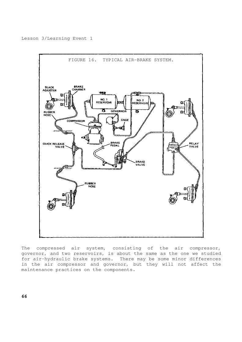
Lesson 3/Learning Event 1
FIGURE 16. TYPICAL AIR-BRAKE SYSTEM.
The compressed air system, consisting of the air co mpressor, governor, and two reservoirs, is about the same as the one we studied for air-hydraulic brake systems. There may be some minor differences in the air compressor and governor, but they will n ot affect the maintenance practices on the components. 66

Lesson 3/Learning Event 1 An air line connects the compressed air in the rese rvoirs to the brake valve. The brake pedal operates the lever on the brake valve. When the brake pedal is depressed, it opens a valve in the brake valve and measures a certain amount of compressed a ir from the reservoirs to go to the front and rear axles.
FIGURE 17. QUICK-RELEASE VALVE.
The air line from the brake valve to the front axle goes to a component known as a quick-release valve. When the brakes are applied, the quick-release valve directs compressed air to the right and left front brake chambers. When the pedal is r eleased, the air from the brake chambers escapes out of the quick-re lease valve and releases the front brakes. The air in the line fro m the brake valve escapes through the exhaust valve in the brake valv e.
67
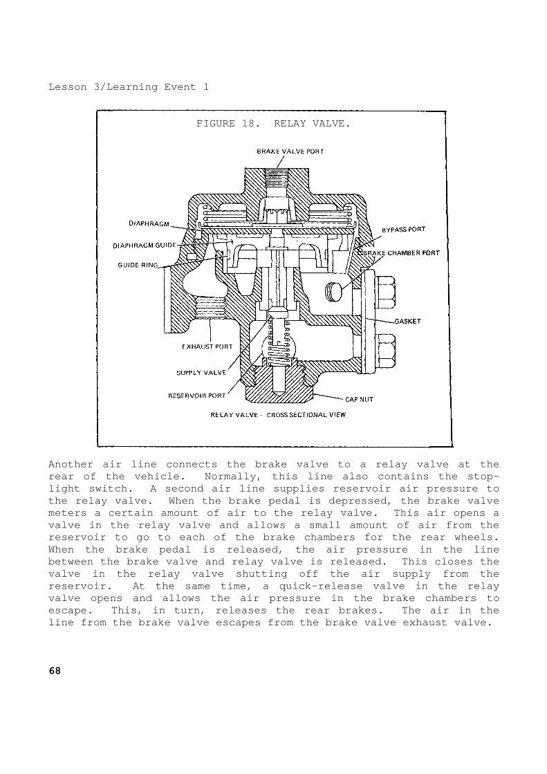
Lesson 3/Learning Event 1
FIGURE 18. RELAY VALVE.
Another air line connects the brake valve to a rela y valve at the rear of the vehicle. Normally, this line also cont ains the stop-light switch. A second air line supplies reservoir air pressure to the relay valve. When the brake pedal is depressed , the brake valve meters a certain amount of air to the relay valve. This air opens a valve in the relay valve and allows a small amount of air from the reservoir to go to each of the brake chambers for t he rear wheels. When the brake pedal is released, the air pressure in the line between the brake valve and relay valve is released . This closes the valve in the relay valve shutting off the air suppl y from the reservoir. At the same time, a quick-release valve in the relay valve opens and allows the air pressure in the brak e chambers to escape. This, in turn, releases the rear brakes. The air in the line from the brake valve escapes from the brake va lve exhaust valve. 68

Lesson 3/Learning Event 1 The amount of braking action applied to the truck w heels depends on how far down the brake pedal is depressed. When th e pedal is pressed way down, a greater amount of air pressure is appli ed to the brake chambers. This causes the brake shoes and linings to press harder against the brake drums, providing greater braking action.
FIGURE 19. BRAKE CHAMBER.
The brake chambers at each wheel convert air pressu re to mechanical motion. When air enters the air inlet, it moves th e diaphragm which moves the pushrod.
69

Lesson 3/Learning Event 1
FIGURE 20. SLACK ADJUSTER.
The pushrod of the brake chamber is connected to a slack adjuster. The slack adjuster serves two purposes: to change t he back and forth motion of the pushrod to rotary motion and to make minor adjustments to the brake shoes and linings. The slack adjuster is splined to one end of a shaft that goes through the backing plate of the wheel brake. The other en d of the shaft contains a cam. When the brake chamber pushrod mov es the end of the slack adjuster, it causes the shaft to rotate. As the cam on the brake end of the shaft rotates, it causes the brake shoes with linings to move against the drum. Minor adjustment of the brakes is made by rotating the worm shaft on the slack adjuster. The wheel brake assemblies are much the same as tho se for hydraulic or air-hydraulic systems. The main difference is t he wheel cylinder is replaced with an operating cam. 70

Lesson 3/Learning Event 1 AUXILIARY COMPONENTS Some wheeled vehicles require special controls on t he braking system. If we consider a 4x4 truck tractor, for example, we know that its primary job is to pull a semitrailer. Under normal driving conditions when the road is dry, the braking system will work well. When the road is wet and slippery, though, the trac tor and trailer will jackknife if the front wheels of the tractor b rake too much. To prevent this from happening, the front quick-releas e valve contains a limiting valve. A two-way valve is also provided t o control the limiting valve. The two-way valve is mounted in the vehicle cab whe re the operator can reach it easily. The valve has dry and slipper y road positions. An air line connects the valve to the brake valve a nd another line goes from the two-way valve to the combined limitin g and quick-release valve at the front axle. When the valve is in the dry road position, no air can pass through the two-way valve to the front axle. However, when the valve is in the slippery road position, air from the brake valv e passes through the two-way valve and onto the quick-release valve. When this air acts on the limiting device in the quick-release va lve, it only allows a small amount of air coming from the brake valve to go to the brake chambers. This will reduce the amount of bra king action on the front wheels and prevent the front brakes from lock ing which would cause the tractor and trailer to jackknife. Trucks and truck tractors that pull heavy trailer l oads must also have a control that will allow the operator to appl y the trailer brakes separately from the truck or tractor brakes. This device is known as an independent trailer control valve and i s usually mounted on the truck steering column. Notice in the paragr aph above that the valve is connected to reservoir air pressure throug h the manifold fitting for auxiliary devices. The hand lever on the valve allows the operator to apply line air pressure to the double-check valve at the rear of t he vehicle. This valve allows pressure to be applied on the trailer brakes through the trailer service line connection. Notice that the double-check valve also has a line coming to it from the brake valve. In this way, the trailer brakes c an be operated when the truck brakes are applied or they can be ap plied alone with the use of the trailer control in the cab.
71
Lesson 3/Learning Event 1 SEMITRAILER AIR-BRAKE SYSTEMS Most larger trailers equipped with air-brake system s use a service air line and an emergency air line connection to th e tractor that tows the trailer. The trailer brake system consist s of one or more reservoirs, relay emergency valve, brake chamber an d slack adjuster for each wheel, and the connecting air lines. When the emergency line is connected to the tractor and the connection valve is opened, air will flow from the truck reservoir to the trailer relay valve and into the reservoir. Th is raises the air pressure at the trailer to the same pressure as tha t of the truck and holds the quick-release valve in the relay emergenc y valve open. The compressed air in the trailer reservoir is now avai lable to make the trailer brakes work. When the truck brake pedal is depressed or the trai ler brake control lever is moved, compressed air will move through th e service line between the tractor and trailer to the top of the r elay emergency valve on the trailer. The compressed air will close the release valve and open another valve in the relay emergency valve allowing air fro m the trailer reservoirs to go to each wheel brake chamber on the trailer. This applies the brakes. When pressure on the service line is released, the air supply from the trailer reservoir to the brake chambers is shut off. At the same time, the quick-release valve in the emergency rela y valve is opened so that the air in the brake chambers can escape an d release the trailer brakes. The relay emergency valve is designed to lock the t railer brakes in case the trailer ever breaks away from the tractor. If, for some reason, the emergency air supply line becomes disco nnected from the tractor, there will be no air pressure applied wher e the air enters the relay emergency valve. Without pressure the qu ick-release valve will close and allow air pressure from the reservoi r to go to the brake chambers. This will lock all brakes on the t railer. The brakes will remain locked as long as the air pressu re in the trailer reservoir remains high enough. However, as soon as a supply of air is hooked to the emergency line again, the pressure will open the quick-release valve, close off the air supply to th e chambers, and the brakes will release. The brakes can also be re leased by draining the air from the reservoir. 72

Lesson 3/Learning Event 2 Learning Event 2: DESCRIBE THE OPERATION OF THE STRAIGHT AIR-BRAKE SY STEM OPERATION OF STRAIGHT AIR-BRAKE SYSTEM So far, we have discussed the components contained in air-brake systems and what they do. Knowledge of how the com ponents function is important so that a mechanic can diagnose troubl es without making errors. As mentioned before, the components of the compress ed air system are about the same as those used in 2 1/2- and 5-ton tr ucks. The operation of air compressors, governors, reservoirs , high-pressure relief valves, and drain cocks of air-brake systems is the same as those discussed in earlier lessons for air-hydrauli c systems. Again, in this system, the maximum pressure is about 105 P SI. The brake valve (or brake application valve) is the device that an operator uses to control pressure to the brakes. I t is mounted under the floor of the cab and is controlled by brake ped al movement. It is made so that the driver can vary the air pressur e admitted to the brake chambers. As we will see later, the more air pressure there is in the brake chamber, the more the brake shoes will be forced against the brake drum. There are several types of brake v alves, but they all do about the same job. The main difference bet ween the types is that some are operated by the foot pedal only, whil e others are operated by a foot pedal but have a hand-operated l imit control. Standard brake valves are fitted with a lever that is connected and operated by a foot pedal. As the lever is moved toward its fully applied posi tion, mechanical force is applied to the top of the diaphragm in the brake valve. This is done by the action of the plunger and press ure regulating spring assembly. As the diaphragm moves downward, a force is applied to the middle of the rocker arm and onto the inlet and exhaust valve. Because the exhaust valve spring is weaker than the inlet valve spring, the exhaust valve is forced down onto its s eat before the inlet valve is forced down to open.
73

Lesson 3/Learning Event 2 When the inlet valve opens, air pressure flows from the reservoir through the valve to the brake chambers. This appl ies the brakes. When the air pressure being delivered to the brake chambers, from the opening below the diaphragm, overcomes the mechanic al force being applied to the top of the diaphragm, the diaphragm lifts. This permits the inlet valve to close preventing any fur ther rise of air pressure in the brake chambers, while the exhaust v alve remains closed and prevents any escape of air pressure. If the driver pushes the foot pedal farther down, m ore mechanical force is applied to the top of the diaphragm. When this happens, more pressure is delivered to the brake chamber and is applied to the brakes. If the driver lets the pedal move toward its releas ed position, the force on top of the diaphragm is reduced. Air pres sure below the diaphragm overcomes the mechanical force on top of it, and the diaphragm lifts slightly. When this happens, the i nlet valve remains closed and the exhaust valve opens. This exhausts air pressure from the brake chambers until the air pressure below the diaphragm again balances the mechanical force on top of it. If the driver lets the foot pedal return to the ful ly released position, the exhaust valve remains open. Thus, al l the pressure from the brake chamber is exhausted, and the brakes are fully released. If the driver pushes the pedal down to the fully ap plied position, the pressure regulating spring is compressed until the spring guide strikes the spring slat. This holds the rocker arm down, the inlet valve is held open, and full reservoir pressure is allowed to pass through the brake valve to the brake chambers. The trailer brake control valve is used to apply an d release the trailer brakes without applying the brakes of the t owing vehicle. This type valve is usually mounted on the steering column or on the instrument panel. The driver may put the handle in any one of several positions between the released and fully ap plied position. 74

Lesson 3/Learning Event 2 As the handle of the brake valve is moved toward th e applied position, force is applied to the top of the pressu re regulating spring. When this happens, the spring and piston a ssembly move downward and the exhaust valve seat engages the exh aust valve. This closes the passage to the exhaust port. The exhaus t and inlet valves, being part of the same assembly, cause both valves to move together. After the exhaust valve is closed and th e piston assembly continues to move downward, the inlet valve is forc ed off its seat. This lets air pressure from the reservoir pass thro ugh the inlet valve and out the brake chamber port to the connect ion leading to the service line and the brakes on the trailer. As soon as the air pressure below the piston assemb ly overcomes the mechanical force on top of it, the piston assembly lifts and the intake valve closes. The closing of the inlet valv e stops the airflow from the reservoir. The exhaust valve rema ins closed preventing any loss of air through the exhaust port . If the brake valve handle is moved farther toward t he fully applied position, it adds more mechanical force on top of t he piston assembly and increases the delivered air pressure. If the brake valve handle is moved toward the relea sed position, the mechanical force on top of the piston assembly is d ecreased. The air pressure below the piston assembly lifts it slightl y, opening the exhaust valve and permitting air pressure to exhaus t from the service line. When the air pressure under the piston and t he mechanical force on top of the piston is again equal, the exha ust valve will close. When the brake valve handle is moved to the released position, the intake valve is closed, the exhaust v alve is opened, all air pressure is exhausted from the brake cylind ers, and the brakes are released. Another device in air-brake systems is the quick-re lease valve. The purpose of this valve, as the name suggests, is to speed up the release of the applied brakes. When air pressure from the brake valve enters the b rake valve port of the valve, the diaphragm moves down and closes the exhaust port. Air pressure then goes around the outer edges of the di aphragm and flows out the side connections (brake chamber ports) to t he brake chambers. This applies the brakes.
75
Lesson 3/Learning Event 2 As soon as the pressure in the brake chamber and co nnecting lines equals the brake valve pressure above the diaphragm , the force of the spring below the diaphragm forces the outer edge of the diaphragm back up against the body. At the same time, the ce nter of the diaphragm keeps the exhaust port closed. This is t he holding position. If the brake valve pressure on top of the diaphragm is reduced, the brake chamber pressure raises the diaphragm. This opens the exhaust port and lets the brake chamber pressure escape thr ough the exhaust port. If the brake valve pressure on top of the di aphragm is only partially released, the diaphragm goes to the holdi ng position as soon as the pressure above and below it is equal. As stated earlier, a relay valve is used on the rea r wheels of trucks to speed up the application and release of the rear brakes. When the valve is in the released position, the res ervoir pressure is in the cavity below the supply valve which is close d. The diaphragm is in its normal position resting on the diaphragm guide. When the brake valve is applied, it sends air throu gh the brake valve port into the cavity above the diaphragm. The pres sure pushes the diaphragm down. When the diaphragm moves down, its outer edge seals the exhaust port and the center of the diaphragm fo rces the diaphragm guide and the supply valve down. This opens the su pply valve and allows air pressure from the reservoir to flow thro ugh the supply valve and into the cavity below the diaphragm. Thi s cavity is connected through the brake chamber port to the bra ke chambers. With the mechanism in this position, air pressure is flo wing directly from the reservoir through the relay valve into the brak e chambers applying the brakes. As soon as the air pressure below the diaphragm equ als the air pressure above the diaphragm, the force of the supp ly valve spring lifts the center of the diaphragm and closes the su pply valve. This limits the air pressure being delivered to the brak e chambers by the relay valve to the same pressure as that being deli vered by the brake valve to the relay valve. In this position, the su pply valve is closed and the force of air pressure on top of the diaphragm keeps the outer edge of the diaphragm down sealing the ex haust port. An increase in brake valve pressure repeats the action (as in the applying position) until the two pressures are agai n equal. 76

Lesson 3/Learning Event 2 If the brake valve pressure above the diaphragm is reduced, the brake chamber pressure below the diaphragm lifts the diap hragm. This opens the exhaust port under the outer edge of the diaphr agm, and the pressure in the brake chamber is exhausted until a lower balanced pressure is reached. If the air pressure delivered by the brake valve drops to zero, the relay valve releases all p ressure from its brake chamber. This releases the brakes and the va lve returns to its released position. A relay emergency valve is used in the air-brake sy stem of trailers. This valve acts as a relay during operation of the brakes. It also automatically applies the trailer brakes when the a ir lines to the towing vehicle are disconnected or broken. The ope ration of the relay portion of the valve is much the same as the truck relay valve during normal operation. However, what happens if the air line is disconnected or if the trailer breaks away from the towing vehicle is quite different. The relay emergency valve is made to go into its em ergency position and apply the trailer brakes when there is a quick drop in pressure in the cavity below the emergency diaphragm. For e xample, if the emergency line is broken, air pressure in the cavit y below the emergency diaphragm would flow out of the broken em ergency line. Air pressure above the emergency diaphragm will pus h the diaphragm down and pull the upper emergency valve down, closi ng it. Air pressure above the check valve will hold it down an d closed. Air pressure from the trailer reservoir can now flo w across the top of the depressed emergency diaphragm into the cavit y leading to the brake chambers applying the brakes. As air pressure escapes from below the emergency di aphragm, pressure above the pressure regulating diaphragm drops insta ntly. The spring below the pressure regulating diaphragm pushes it u p, thus, closing the pressure regulating valve. Air pressure in the trailer reservoir is prevented from escaping through the broken line by the closed upper emergency valve. To release the trailer brakes, the air reservoir wi ll have to be drained of air or the emergency line reconnected to the towing vehicle.
77

Lesson 3/Learning Event 2 When the trailer emergency line is connected to the emergency line of the towing vehicle, air flows from the tractor rese rvoir, through the emergency line, and into the relay emergency valve. This airflow lifts the check valve and flows over the top of the emergency diaphragm into the supply line to charge the traile r reservoir. At the same time, air has also been flowing below the emergency diaphragm and into the cavity above the pressure re gulating diaphragm. Air continues to flow in this manner un til the air pressure in the cavity above the pressure regulatin g diaphragm reaches about 70 PSI. Brake chambers are mounted at each wheel. Their pu rpose is to convert the energy of compressed air into the mecha nical force and motion necessary to operate the brakes. One type of brake chamber consists mainly of a housing, diaphragm and pushrod , and a spring. As compressed air enters the brake chamber behind t he diaphragm, the diaphragm forces the adjuster lever which rotates a shaft and cam to apply the brakes. The higher the air pressure admi tted to the brake chamber, the greater the force on the pushrod. Whe n the air pressure is released from the brake chamber, the spring retu rns the pushrod and diaphragm to the released position. Instead of the brake chamber discussed above, some vehicles use a rotochamber. As air pressure enters the rotochambe r behind the diaphragm, it moves the diaphragm forward. The dia phragm moves along the inside wall of the cylinder body with a rolling motion. This motion of the diaphragm forces the pushrod forward. The higher the air pressure admitted to the rotochamber, the great er the force on the pushrod. If all the air pressure is released f rom the rotochamber, the spring returns the diaphragm and p ush-rod to the released position. The air cylinder is another version of a brake cham ber. When air enters the compressed air opening and goes behind t he piston, the piston will move, driving the pushrod and compressi ng the piston. When air pressure in back of the piston is released , the piston spring returns the piston and pushrod to the releas ed position. A slack adjuster is used in air-brake systems to co nvert back and forth motion to rotary motion and to provide a quic k and easy way to adjust the brakes to compensate for brake lining we ar. All slack adjusters consist mainly of a worm and gear contain ed in a body having a lever arm. The gear is splined to fit the brake camshaft. In normal braking, the entire slack adjuster moves as one solid unit. It acts as a simple lever to transmit brake chamber forces to the brake camshaft as the brakes are applied. All adju stments are made by turning the worm shaft. This turns the worm ge ar and brake camshaft and moves the brake shoes either closer to or farther from the brake drum. 78

Lesson 3/Learning Event 2 MISCELLANEOUS COMPONENTS So far, we have only discussed the main components of air-brake systems. Included in the system are smaller items such as check valves, shutoff valves, safety valves, hoses, lines , and fittings. The organizational mechanic will be required to mai ntain all of these. Maintenance that will have to be done on these item s by the organizational mechanic is much like that on the ai r-hydraulic system. This maintenance will again be inspecting, testing, adjusting, repairing, and replacing worn or defecti ve parts. Repair will consist mainly of tightening and replacing par ts. Keep in mind that air leaks are your biggest enemy. Be sure to tighten all connections properly so you will not ha ve a loss of air pressure.
79
Lesson 3/Learning Event 3 Learning Event 3: DESCRIBE INSPECTION PROCEDURES FOR THE STRAIGHT AIR-BRAKE SYSTEM INSPECTION AND ROAD TEST The inspection and road test of wheeled vehicles to determine the condition of the brake system is about the same reg ardless of whether the brakes are air or air-hydraulic. Therefore, ex cept for a few special air-brake components, the inspection and te st is made similar to that for 2 1/2- and 5-ton vehicles. The inspection consists of checking the air hoses, fittings, chambers, cylinders, and linkage for looseness or d amage. Also check for water in the air reservoirs. Then start the en gine and observe the air pressure buildup. Check for leaks in the l ines, fittings, and components by stopping the engine and seeing if the air pressure gage drops noticeably in a period of one minute. I f it does, more testing for leaks is required. If a visual inspection indicates that the brake sys tem seems to be in good condition, road-test the vehicle to see just h ow well the brakes operate. During the road test, check for side pull , noise, or clatter. Make several stops to be sure of this che ck. Immediately after the road test, check the temperature of the b rake drums. If they are too hot, the brakes are dragging; if one i s too cool, the wheel brake is not operating. If any deficiencies are noted during the inspection and road test, they must be corrected. We will discuss some of th e test and replacement procedures for those air-brake componen ts that are different from the ones on hydraulic or air-hydraul ic systems. Table 1 provides a troubleshooting guide for the service brake system. 80

Lesson 3/Learning Event 3
Table 1. Troubleshooting Service Brakes.
81

Lesson 3/Learning Event 3
Table 1. Troubleshooting Service Brakes (Continued ).
82
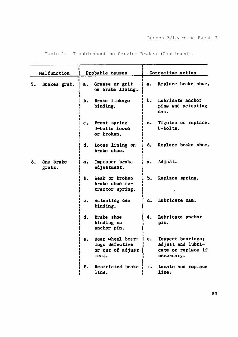
Lesson 3/Learning Event 3
Table 1. Troubleshooting Service Brakes (Continued ).
83
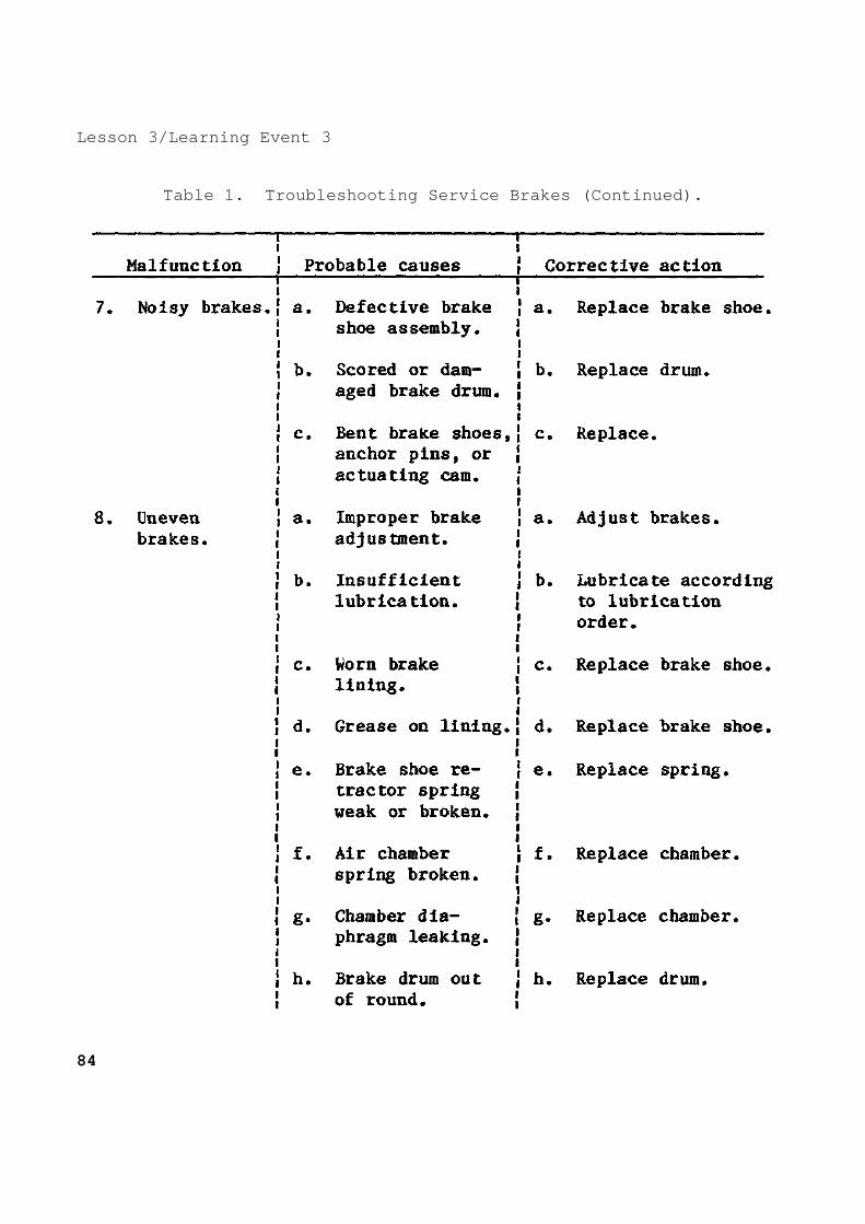
Lesson 3/Learning Event 3
Table 1. Troubleshooting Service Brakes (Continued ).
84

Lesson 3/Learning Event 3
Table 1. Troubleshooting Service Brakes (Continued ).
85

Lesson 3/Learning Event 3
Table 1. Troubleshooting Service Brakes (Continued ).
86

Lesson 3 PRACTICE EXERCISE 1. Which component of a six-wheel truck air-brake s ystem receives
air pressure from the brake valve and also from the air reservoir?
a. Front brake chamber b. Governor c. Relay valve 2. What is the purpose of the slack adjuster used i n air-brake
systems? a. Ensure the trailer brakes are applied first b. Compensate for brake lining wear c. Ensure a fast release of the trailer brakes 3. While inspecting a brake system, you find the le ft front wheel
brake is slow to apply. What is probably at fault? a. Quick-release valve b. Application valve c. Brake chamber 4. Most trailer air-brakes are operated through a. two-way valves. b. relay valves. c. emergency relay valves. 5. Which device in an air-brake system is used by t he driver to
control brake application? a. Relay valve b. Quick-release valve c. Brake valve
87
Lesson 3 ANSWERS TO PRACTICE EXERCISE 1. c (page 68) 2. b (page 78) 3. c (page 81) 4. a (page 71) 5. c (page 73) 88