Embed Size (px)
Citation preview

U.S. Army Corps of Engineers – Alaska District
DRAFT
Site Investigation/Feasibility Study Report, Cape Yakataga Radio Relay Station, Cape Yakataga, Alaska
Prepared by
LOGO DELETED FOR CLIENT PRIVACY
March 2002
Contract No. DACA85-98-D-0017 Delivery Order No. 0024 PRIVATE CLIENT Document No. 9000-248-3Qtr

CAPE YAKATAGA SI/FS REPORT DRAFT
9000-248-610 i March 2002
CONTENTS
LIST OF ACRONYMS AND ABBREVIATIONS...................................................................................vi EXECUTIVE SUMMARY..................................................................................................................... 1 1.0 INTRODUCTION ................................................................................................................. 1-1
1.1 Report Outline ......................................................................................................... 1-1 1.2 Cape Yakataga Radio Relay Station Description and History ................................. 1-2 1.3 Regional Setting ...................................................................................................... 1-5
1.3.1 Geology....................................................................................................... 1-5 1.3.2 Hydrogeology .............................................................................................. 1-6 1.3.3 Meteorology ................................................................................................ 1-6 1.3.4 Surrounding Land Use ................................................................................ 1-6
1.4 Sensitive Ecosystems.............................................................................................. 1-7 1.4.1 Background Soil and Groundwater Data ..................................................... 1-7
2.0 PREVIOUS INVESTIGATIONS ........................................................................................... 2-1 2.1 1992 Inventory Project Report ................................................................................. 2-1 2.2 1996 Preliminary Assessment/Site Investigation ..................................................... 2-1 2.3 1998-1999 Petroleum Release and LeachfieldLeachfield Investigation,
Underground Storage Tank Removal Action and Site Investigations ...................... 2-3 2.4 1998 Septic Tank Contents Characterization and Disposal Plan............................. 2-5
3.0 FIELD INVESTIGATION PROGRAM................................................................................... 3-1 3.1 Site Clearance ......................................................................................................... 3-1 3.2 Site Visit................................................................................................................... 3-1 3.3 Ambient Temperature Headspace Screening.......................................................... 3-2 3.4 Test Holes ............................................................................................................... 3-2 3.5 Soil Borings ............................................................................................................. 3-5
3.5.1 Surface Soil Sampling ................................................................................. 3-6 3.6 Monitoring Well Installation...................................................................................... 3-7 3.7 Monitoring Well Construction................................................................................... 3-7 3.8 Well Development.................................................................................................... 3-8 3.9 Water Level Measurements..................................................................................... 3-8 3.10 Groundwater Sampling ............................................................................................ 3-9 3.11 Field Quality Control Samples ................................................................................. 3-9 3.12 Sample Management............................................................................................. 3-10
3.12.1 Sample Identification ................................................................................. 3-10 3.12.2 Sample Packaging and Transport ............................................................. 3-13 3.12.3 Field and Sample Custody Documentation ............................................... 3-13
3.13 Field Documentation.............................................................................................. 3-14 3.14 Field Equipment Calibration................................................................................... 3-15 3.15 Decontamination Procedures ................................................................................ 3-15 3.16 Other Activities....................................................................................................... 3-16
3.16.1 Tidal Influence Monitoring ......................................................................... 3-16 3.16.2 Groundwater Probe Rehabilitation ............................................................ 3-16 3.16.3 Site Survey................................................................................................ 3-16

CAPE YAKATAGA SI/FS REPORT DRAFT
9000-248-610 ii March 2002
3.17 Investigation-Derived Waste.................................................................................. 3-17 3.17.1 Soil IDW .................................................................................................... 3-18 3.17.2 Liquid IDW................................................................................................. 3-18 3.17.3 Hazardous Waste...................................................................................... 3-19 3.17.4 Other IDW ................................................................................................. 3-19
3.18 Streamlined Risk Assessment and Cleanup Criteria ............................................. 3-19 4.0 NATURE AND EXTENT OF CONTAMINATION.................................................................. 4-1
4.1 Ravine Area and Ravine Area Drainage.................................................................. 4-1 4.1.1 Soil Contamination ...................................................................................... 4-1 4.1.2 Surface Water Contamination ..................................................................... 4-2
4.2 Aboveground Storage Tank (AST) Area .................................................................. 4-2 4.2.1 Soil Contamination .....................................................................................4-94.2.2 Groundwater Contamination ....................................................................... 4-9
4.3 Composite Building Area (CBA)............................................................................... 4-9 4.3.1 Soil Contamination .................................................................................... 4-10 4.3.2 Groundwater Contamination ..................................................................... 4-10 4.3.3 PCB Contamination................................................................................... 4-11
4.4 Possible Disposal Area (PDA) ............................................................................... 4-21 4.4.1 Soil Contamination .................................................................................... 4-21 4.4.2 Groundwater Contamination ..................................................................... 4-21
4.5 Fuel Pipeline and Off-Loading Area....................................................................... 4-22 4.5.1 Soil Contamination .................................................................................... 4-22
5.0 IDENTIFICATION AND SCREENING OF TECHNOLOGIES .............................................. 5-1 5.1 Removal Action Objectives...................................................................................... 5-1 5.2 Cape Yakataga RRS Remediation .......................................................................... 5-1 5.3 General Response Actions ...................................................................................... 5-2 5.4 Estimated Volumes or Areas of Contaminated Media ............................................. 5-2 5.5 Applicable or Relevant and Appropriate Requirements ........................................... 5-3 5.6 Identification of Technology Types and Process Options ........................................ 5-4
5.6.1 Remedial Technologies for Surface and Subsurface Soil ............................. 5-4 5.6.2 Remedial Technologies for Groundwater ................................................... 5-13
5.7 Screening of Technologies ..................................................................................... 5-20 6.0 IDENTIFICATION AND ANALYSIS OF REMEDIAL ACTION ALTERNATIVES.................. 6-1
6.1 Identification of Alternatives..................................................................................... 6-2 6.1.1 Alternative 1 ................................................................................................ 6-2 6.1.2 Alternative 2 ................................................................................................ 6-4 6.1.3 Alternative 3 ................................................................................................ 6-5 6.1.4 Alternative 4 ................................................................................................ 6-7
7.0 COMPARATIVE ANALYSIS OF REMEDIAL ACTION ALTERNATIVES............................. 7-1 7.1 Overall Protection of Human Health and the Environment ...................................... 7-1 7.2 Compliance with ARARs.......................................................................................... 7-1 7.3 Long-Term Effectiveness and Permanence............................................................. 7-2 7.4 Reduction of Toxicity, Mobility, or Volume through Treatment................................. 7-2 7.5 Short-Term Effectiveness ........................................................................................ 7-2

CAPE YAKATAGA SI/FS REPORT DRAFT
9000-248-610 iii March 2002
7.6 Implementability....................................................................................................... 7-2 7.7 Cost ......................................................................................................................... 7-2 7.8 State Acceptance..................................................................................................... 7-2 7.9 Community Acceptance........................................................................................... 7-3
8.0 RECOMMENDATIONS AND CONCLUSIONS.................................................................... 8-1 8.1 Conclusions ............................................................................................................. 8-1 8.2 Pre-removal Action Recommendations ................................................................... 8-1
9.0 REFERENCES .................................................................................................................... 9-1
APPENDICES
A QUARTERLY WATER LEVELS B PREVIOUS INVESTIGATIONVE RESULTS AND FIGURES C TEST HOLE, SOIL BORING, AND MONITORING WELL LOGS D GEOTECHNICAL DATA E PHOTOGRAPHS F INVESTIGATION-DERIVED WASTE MANIFESTS G METHOD 3 CALCULATIONS H SI/FS ANALYTICAL DATA I CHEMICAL DATA QUALITY REPORT J DATA QUALITY MEMORANDASI/FS ANALYTICAL RESULTS F SITE PHOTOGRAPHS G INVESTIGATION-DERIVED WASTE MANIFESTS H ADEC METHOD THREE CALCULATIONS I COST ANALYSIS SHEETS J CHEMICAL DATA QUALITY REVIEW
LIST OF TABLES
Table 3-1. Soil Contaminants of Concern and Site Specific Cleanup Levels. .............................................3-24 Table 7-1. Cape Yakataga SI/FS – Comparative Analysis of Removal Alternatives. .....................................7-3

CAPE YAKATAGA SI/FS REPORT DRAFT
9000-248-610 iv March 2002
LIST OF FIGURES
Figure 1-1. Yakataga Radio Relay Site.....................................................................................................1-3 Figure 1-2. Site Layout Map......................................................................................................................1-9 Figure 1-34. Groundwater Contours for November 6, 2001..........................................................................1-9 Figure 1-5. Groundwater Contours for August 18, 2001..............................Error! Bookmark not defined. Figure 1-6. Groundwater Contours for May 21, 2001. ............................................................................1-15 Figure 1-7. Groundwater Contours for November 15, 2000. ..................................................................1-17 Figure 1-8. Cape Yakataga RRS Site Layout.............................................................................................1-19 Figure 3-1. Test Hole, Soil Boring, Monitoring Well, and Groundwater Probe Location Map. .................3-3 Figure 4-1. Soil Analytical Results and Soil Contaminant Plume Map. ....................................................4-3 Figure 4-2. Groundwater Probe and Surface Water Analytical Results and Groundwater Contaminant Plume Map. ................................................................................................................................................4-5 Figure 4-3. Monitoring Well Analytical Results and Groundwater Contaminant Plume Map. ..................4-7 Figure 4-4. Composite Building and Radio Relay Building Entryway Locations.....................................4-17 Figure 4-5. Composite Building Schematic of PCB Soil Sample Results...............................................4-18 Figure 4-6. Radio Relay Building Schematic of PCB Soil Sample Locations. ........................................4-19 Figure 4-7. Off-Site Laboratory PCB Analytical Results Composite and Radio Relay Building Entryways..................................................................................................................................................................4-20 Figure 4-8. Fuel Off-Loading Header and Fuel Pipeline Soil Sample.....................................................4-23 Figure 1-1. Site Location Map........................................................................................................................

CAPE YAKATAGA SI/FS REPORT DRAFT
9000-248-610 v March 2002
LIST OF ACRONYMS AND ABBREVIATIONS
AAC Alaska Administrative Code
ACL alternative cleanup level
ADEC Alaska Department of Environmental Conservation
AMSL Above mean sea level
AOC Area of concern
ARAR Applicable or Relevant and Appropriate Requirement
AST Aboveground storage tank
ASTM American Society for Testing and Materials
ATH Ambient temperature headspace
bgs Below ground surface
BNA Base neutral acid
BOD Biological exygen demand
BTEX Benzene, toluene, ethylbenzene, and total xylenes
C Celsius
CBA Composite Building Area
CCD Charley Creek Drainage
CDQR Chemical Data Quality Review
CERCLA Comprehensive Environmental Response, Compensation, and Liability Act
CFR Code of Federal Regulations
COC Chemical of concern
COD Chemical oxygen demand
COPC Chemical of potential concern
CSRP Contaminated Sites Remediation Program
cy Cubic yard
DERP Defense Environmental Restoration Program
DRO Diesel range organics
E&E Ecology & Environment, Inc.
EPA U.S. Environmental Protection Agency
ERS Energy Recovery Services
F Fahrenheit

CAPE YAKATAGA SI/FS REPORT DRAFT
9000-248-610 vi March 2002
FOLH Fuel Off-Loading Header
FPL Fuel Pipeline
FS Feasibility Study
ft2 Square feet
LIST OF ACRONYMS AND ABBREVIATIONS (Continued)
FUDS Formerly Used Defense Site
GAC granular activated carbon
gal/ft gallons per foot
GRO Gasoline range organics
GSL Geological Society of America, Inc.
HBL Health-based limits
HDPE High-density polyethylene
HHS Heated headspace
HI Hazard index
HLA Harding Lawson Associates
HQ Hazard quotients
IDW Investigation-derived waste
µg/kg Micrograms per kilogram
INPR Inventory Project Report
IRIS Integrated Risk Information System
LECL Laboratory-established control limit
LNAPL light nonaqueous-phase liquid
MCL Maximum contaminant level
mg/kg Milligrams per kilogram
MCL Maximum contaminant level
mL milliliters
mg/L milligrams per liter
mL milliliter
MOGAS motor gasoline
MQL Method quantitation limits
MS/MSD Matrix spike/matrix spike duplicate
ORC Oxygen Release Compound

CAPE YAKATAGA SI/FS REPORT DRAFT
9000-248-610 vii March 2002
PA/SI Preliminary Assessment/Site Investigation
PAH Polycyclic aromatic hydrocarbons
PCB Polychlorinated biphenyl
PDA Possible Disposal Area
PID Photoionization detector
POL Petroleum, oil, and lubricants
PPE Personal protective equipment
ppb parts per billion
ppm Parts per million
PRG Preliminary Remediation Goals
PVC Polyvinyl chloride
QA Quality assurance
LIST OF ACRONYMS AND ABBREVIATIONS (Continued)
QA/QC Quality assurance/quality control
QC Quality control
RAR Remedial Action Report
RBC Risk-based concentrations
RCRA Resource Conservation and Recovery Act
RAO Remedial Action Objective
RRO Residual range organics
SVOC Semi-volatile organic compound
RRS Radio Relay Site
RVA Ravine Area
SI Site Investigation
SI/FS Site Investigation/Feasibility Study
SVE Soil vapor extraction
SVOC semi-volatile organic compounds
SW Solid Waste
TBC To be considered
TCLP toxic characteristic leaching procedure
TOC Total organic carbon
TSCA Toxic Substances Control Act

CAPE YAKATAGA SI/FS REPORT DRAFT
9000-248-610 viii March 2002
USACE U.S. Army Corps of Engineers
USAED-AK U.S. Army Engineer District-Alaska
USAF U.S. Air Force
USCS Unified Soil Classification System
USGS U.S. Geological Survey
UST Underground storage tank
UV Ultraviolet
UTL Upper tolerance limit
VOC Volatile organic compound
Wilder Wilder Construction
WTPH-D State of Washington total petroleum hydrocarbons as diesel
WTPH-G State of Washington total petroleum hydrocarbons as gasoline

CAPE YAKATAGA SI/FS REPORT DRAFT
9000-248-610 E-1 March 2002
EXECUTIVE SUMMARY
The Cape Yakataga Site Investigation (SI)/Feasibility Study (SI/FS) addresses contamination within the former Cape Yakataga Radio Relay Station (RRS) site located in CapaCape Yakataga, Alaska. The purpose of this SI/FS is to evaluate alternatives for selection of an appropriate removal action to address hazardous substances identified at various areas of investigation at the former Cape Yakataga RRS.
The Cape Yakataga RRS is located in southeast Alaska, along the Gulf of Alaska, approximately 120 miles southeast of Cordova and 100 miles southwest of Yakutat. The Cape Yakataga RRS was constructed in 1959 and was operated by the U.S. Air Force (USAF) as a tropospheric communications station under the military’s White Alice Communications System “A” Route until 1974. The site’s primary building, the two-story Composite Building, which served as the operations center and living quarters and contained a mess hall, diesel- powered generators, and maintenance and service shops. The property has been transferred, leased, or owned several times since 1974 and is currently owned by a private party.
Results of pPrevious investigations indicated that petroleum, oil, and lubricants (POL) contaminated soil and groundwater remained on-site exceeding Alaska Department of Environmental Conservation (ADEC) Method Two cleanup levels remained on site. In aAddition,ally several Resource Conservation and Recovery ActCRA (RCRA) metals and polychlorinated biphenylsPCB contamination was documented exceeding regulatory cleanup levels was documented.
In 2000, the U.S. Army Corps of EngineersUSACE initiated the current SI/FS to support development of ADEC Method Three risk based cleanup levels. The goal of the site investigationSI was to characterize site contamination and assess site risks in order to evaluate possible removal actions at five areas of investigation where hazardous substance releases were possible. The areas of investigation consisted of:
1) Tthe Rravine Aarea (RVA) and Rravine Aarea Ddrainage,
2) Tthe Aaboveground Sstorage Ttank (AST)A area,
3) Tthe composite buildingComposite Building Aarea (CBA),
4) Tthe Ppossible Ddisposal Aarea (PDA), and
5) Tthe Ffuel Ooff-Lloading Hheader (FOLH) and the Ffuel Ppipeline.
The streamlined risk evaluation generated alternative cleanup levels (ACLs) for each detected chemical. Through use of the Method 3Three evaluation, ACLs were generated for gasoline range organics, diesel range organics,GRO, DRO, arsenic, and benzo(a)pyrene using

CAPE YAKATAGA SI/FS REPORT DRAFT
9000-248-610 E-2 March 2002
residential scenario. Iron and thallium in soil exceeded the ADEC hazard index of 1. Thallium is the primary contributor to the site hazard index. Additionally,In addition, arsenic and benzo(a)pyrene exceeded the ADEC cancer risk target value of 1x10⁻⁵.
�Based on the results of site characterization and the development of removal action objectives, a limited number of removal action alternatives were developed, and evaluated, and screened with respect to implementability, effectiveness, and cost.
Based on the evaluation criteria, Alternative 4 is the recommended removal action for the Cape Yakataga RRS, as discussed in Section 7.0 of this report –. Alternative 4 involves the following:
• Excavation and off-site disposal of RCRA/Toxic Substances Control Act (TSCA) regulated waste;
• Eexcavation and on-site bioremediation of POLsPOL- contaminated surface soil; and
• In-situ treatment of POL- contaminated subsurface soils and groundwater with with Oxygen Release Compound ORC and natural attenuation.
is the recommended removal action for the Cape Yakataga RRS. Alternative 4 would be the most effective and least costly alternative that is expected to be acceptable to sState regulators and the community.

CAPE YAKATAGA SI/FS REPORT DRAFT
9000-248-610 1-1 March 2002
1.0 INTRODUCTION
The objectives of this Site Investigation/Feasibility Study (SI/FS) areis to provide the U.S. Army Corps of Engineers (USACE) -– Alaska District with the Cape Yakataga Radio Relay Station (RRS) Alaska site investigation findings, develop risk-based cleanup levels, and propose removal action alternatives based on technical concerns and cost balance. The SI/FS was conducted by PRIVATE CLIENT Corporation (PRIVATE CLIENT) under U.S. Army Corps of Engineers (USACE) Contract No. DACA85-98-D-0017, Delivery Order No. 0024. PRIVATE CLIENT’s field team conducted on-site soil, groundwater, and surface water sampling during four quarterly monitoring events conducted between the summer of 2000 and November 2001. PRIVATE CLIENT investigated the following potential contaminant source areas at the Cape Yakataga RRS to delineate the extent of soil and groundwater contamination and determine the need for removal action:
• The Ravine Area (RVA),
• The Aboveground Storage Tank (AST) Area,
• The Composite Building Area (CBA),
• The Possible Disposal Area (PDA), and
• The Fuel Off-Loading Header (FOLH).and the Fuel Pipeline (FPL). and,
• Fuel Off-Loading Header (FOLH).
Several potential contaminant source areas at the Cape Yakataga RRS have been investigated to determine the need for removal action. This SI/FS report presents the Cape Yakataga RRS site description and background and describes the site characterization that has been conducted to support development of removal action alternatives as needed.
1.1 Report Outline
This SI/FS report is divided into the following sections:
• Section 1.0 provides an overview of the SI/FS, discusses the history and use of the Cape Yakataga RRS, and describes the regional setting.
• Section 2.0 discusses previous environmental investigations conducted on site.
• Section 3.0 describes the 2000 and 2001 field activities used for site characterization and provides the results of a streamlined risk assessment for contaminated soils with proposed alternative cleanup levels.

CAPE YAKATAGA SI/FS REPORT DRAFT
9000-248-610 1-2 March 2002
• Section 4.0 discussesgives an interpretation of the nature and extent of contamination, discussed by area.
• Section 5.0 proposes remedial action objectives and describes applicableconducts screening of remedial technologies for the site.
• Section 6.0 identifies and and evaluatespresents an analysis of remedial alternatives based on defined criteria.
• Section 7.0 compares presents a comparative analysis of remedial alternatives withagainst the defined criteria presented in Ssection 6.
• Section 8.0 makes a recommendsation for a a specific remedial alternative to address contamination at the site and identifies perceived data gaps and proposed pre-remedial action recommendations.
• Section 9.0 lists the references cited in this SI/FS.
In addition, the following appendices are provided in this report:
• Appendix A – Quarterly Water Levels.;
• Appendix B – Previous Investigationve Results and Figures.;
• Appendix C – Test Hole, Soil Boring, and Well Logs.;
• Appendix D – Geotechnical Data.;
• Appendix E – SI/FS Analytical Results.;
• Appendix F – Site PhotosPhotographs.;
• Appendix G -– Investigation-Derived Waste (IDW) Manifests.;
• Appendix H – Alaska Department of Environmental Conservation (ADEC) Method Three Calculations.;
• Appendix I – Chemical Data Quality Review.;Cost Analysis Sheets; and
• Appendix J – Cost Analysis SheetsChemical Data Quality Review.
1.2 Cape Yakataga Radio Relay Station Description and History
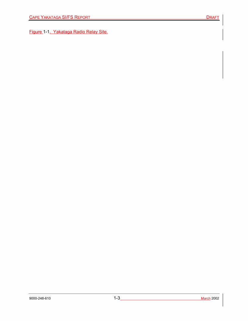
The Cape Yakataga RRS is located in southeast Alaska, along the Gulf of Alaska, approximately 120 miles southeast of Cordova and 100 miles southwest of Yakutat (Figure 1-1).
CAPE YAKATAGA SI/FS REPORT DRAFT
9000-248-610 1-3 March 2002
Figure 1-1. Yakataga Radio Relay Site.

CAPE YAKATAGA SI/FS REPORT DRAFT
9000-248-610 1-4 March 2002
The Chugach Mountain Range extends east west to the north of the Cape, and Brower Ridge lies to the immediate northeast. Sensitive wetlands border the station to the south. The RRS is in Township 21 South, Range 17 East, Section 25, Copper River Meridian, Alaska. The location coordinates can be further described as Latitude 60° 04' 15" North, Longitude 142° 26' 10" West.
The Cape Yakataga RRS (Figure 1-2) was constructed in 1959 and was operated by the U.S. Air Force (USAF) until 1974. The site served as a tropospheric communications station under the military’s White Alice Communications System “A” Route. The primary structure of the original station’s primary structure is the two-story Composite Building. The building served as the operations center and living quarters and contained a mess hall, diesel powereddiesel-powered generators, and maintenance and service shops. Other permanent buildings consisted of a radio relay building and a water treatment and pump house building. In addition, the followingOther support facilities and structures were (or are) at the station (Ecology & Environment, Inc. [E&E] 1997) included :
• four communications antennas with accompanying signal feed towers,
• two 130,000-gallon diesel ASTs,
• one 10,000-gallon diesel AST, one 7,500-gallon gasoline AST,
• one 20,000-gallon diesel underground storage tank (UST),
• one 500-gallon motor gasoline (MOGAS) UST,
• one 110-gallon gasoline UST,
• fuel delivery pipelines,
• a fuel offloading header,
• an aboveground water tank, and
• a septic tank and adjoining septic drain field (E & E 1997).
On-site activities in support of the White Alice Communications System included the following:
• handling of Ffuel handling (diesel and gasoline) for heating, electric power, and vehicles;
• generating pPower generation for communication and residential use;
• facility maintainmaintenanceing the facility; and

CAPE YAKATAGA SI/FS REPORT DRAFT
9000-248-610 1-5 March 2002
• repairing vehicle and electrical equipment repairand vehicles.
In 1974, the site was leased to Alascom, which then who purchased the real property from the USAF in 1984. Undeveloped property surrounding the station was transferred or returned to various federal, state, federal, and and Nnative agencies. Alascom subleased the property to Alaska Mining and Processing, whicho used the site to supportgold- gold-mining operations and as a bed and breakfast establishment. Since that time, the station has been sold two more times and is currently owned by a private party.
All original buildings, the two 130,000-gallon ASTs, and the main delivery pipeline remain remain at the site. Two ASTs and the three USTs have been removed, along with associated underground piping (Harding Lawson Associates/Wilder Construction [HLA/Wilder] 2000). The two 130,000-gallon ASTs and the main delivery pipeline remain.
1.3 Regional Setting
The station is on coastal lowlands between the Gulf of Alaska and the Robinson Mountains. Surface water at the site generally flows in a southerly direction toward adjacent wetlands and eventually into the Gulf of Alaska. Charley Creek bends around the site and is approximately 150 feet north of the AST Area, and 400 feet east of the Composite Building. The Gulf of Alaska is approximately 750 feet to the south.
The majority of the Cape Yakataga RRS structures are constructed on a a gravel and sand pad that, containsing boulders and large cobbles. The thickness of the pad variesies from 0zero feet in parts of the AST areaAST Area upwards to 10 feet on the southern edge of the site edge, near the PDA.
Figure 1-2 (on page 1-9) shows the Cape Yakataga RRS general site layout.
1.3.1 Geology
Surficial soil deposits in the vicinity ofnear the Cape Yakataga RRS are comprised of stratified alluvial, lacustrine, and marine sediments, including local glacial drift and deltaic deposits (U.S. Geological Survey [USGS] 1967). Local bedrock consists of Upper Tertiary- aged sedimentary rocks consisting of sandstone, siltstone, shale, mudstone, and conglomerate (The Geological Society of America, Inc [GSA] 1994). Sedimentary rocks of the Yakataga Formation, consisting of middle Miocene aged sandstone, siltstone, shale, mudstone, and conglomerates, with abundant micro- and megafauna, are exposed in the intertidal zone southeast of the site. Figure 1-2 shows bedded sedimentary bedrock just offshore south of the site. Bedrock was not encountered on site during this investigation, but based on aerial photography and topography, it is likely that bedrock occurs between 30 to 100 feet below ground surface (bgs) (Aeromap 1995; U.S. Geological Survey [USGS] 1959). Undisturbed soils are predominantly composed of poorly graded sand with varying amounts of silt and gravel. (PRIVATE CLIENT 2001a).

CAPE YAKATAGA SI/FS REPORT DRAFT
9000-248-610 1-6 March 2002
Discontinuous silt has been encountered at depth, at 10 feet bgs at the location of the former 500-gallon mogasMOGAS UST, and to the northwest at varying depths (PRIVATE CLIENT 2001a, HLA/Wilder 2000).
1.3.2 Hydrogeology
Groundwater in the Cape Yakataga area occurs in an unconfined sand and gravel aquifer. In general, groundwater flows to the southwest with a more southerly direction under the CBA. Groundwater beneath the PDA flows in a southeast to southwest direction. Groundwater at the AST areaAST Area is strongly influenced by Charley Creek. Along the eastern side of the AST areaAST Area, groundwater flows in a north and east direction, toward Charley Creek (PRIVATE CLIENT 2001a, 2001b, 2001c, and 2002). Figures 1-3 throughFigure 1-6 show quarterly groundwater contour maps of the Cape Yakataga site and include the . quarterly groundwater contours and flow directions. Figure 1-7 shows the calculated gradients for selected locations determined during the four quarterly sampling events, and the flow directions obtained from measurements collected in the fall of 1998. Appendix A summarizes quarterly groundwater levels.
The water table has been measured between 0.75 and 15.25 feet bgs, depending on location and season. Observed variations in water level range from approximately 2.5 feet bgs in the PDA to 7 feet beneath the pad in the CBA. The wWater levels at the AST areaAST Area has been observed at approximately 5.5 feet bgs. For 2001, the lLowest groundwater levels at the site were observed during the August sampling event while the h. Highest groundwater levels were observed during the November sampling events.
1.3.3 Meteorology
Climate of the areaThe area has a maritime climate is maritime, characterized by relatively mild, often rainy, weather. Mean annual precipitation is approximately 110 inches. Average summer temperatures generally range from the mid 40s to the low 60s degrees Fahrenheit (°F). Winter temperatures generally range from the upper teens to the 30s °F.
1.3.4 Surrounding Land Use
The current land use for the site is presumed to be residential since the property is owned by a private party who resides seasonally at the site. The property north, east, and west of the site is currently undeveloped and heavily forested. Immediately south of the site is a wetland whichthat abuts the beach. The current source of drinking water at the site is a cistern on the roof of the Composite Building. Drinking water for the area-wideareawide Cape Yakataga residents is obtained by the residents from surface water in Charley Creek, upgradient of the Cape Yakataga RRS. Surface water in Charley Creek is primarily rainwater and meltwater runoff from Watson Peak.

CAPE YAKATAGA SI/FS REPORT DRAFT
9000-248-610 1-7 March 2002
1.4 Sensitive Ecosystems
The AST Area and the CBA areas are essentially cleared of vegetation becauseas a result of the gravel pad construction of the gravel pad. The habitat immediately north, east, and west of the site is comprised primarily of Sitka spruce forest. Sparse undergrowth in the forest area consists of ferns, blueberry bushes, salmonberry bushes, moss, and devil’s club . The PDA area is located in a wetland area. Vegetation in the wetland consists of salmonberry bushes, alders, Sitka spruce, grasses, skunk cabbage, and devilsdevil’s club. Seasonal surface water is present at various locations throughout the PDA.
South of the wetland is a beach shoreline, as well as intertidal, subtidal, and open water habitat of the Gulf of Alaska.
1.4.1 Background Soil and Groundwater Data
Mean concentrations of 35 elements have been estimated for surficial soil samples from collection locations throughout Alaska (USGS 1988). These background values were used to evaluate the Cape Yakataga RRS metals concentrations in soil. Site data wereas first compared to ADEC soil cleanup levels. If the site soil samples had a concentration of metal greater than the corresponding ADEC cleanup level, the sample was then compared to the Statewide Background Data. This procedure for comparing on-site metals concentrations in soil to background values was used as a screening procedure for determining if additional investigation of metals is warranted.

CAPE YAKATAGA SI/FS REPORT DRAFT
9000-248-610 1-8 March 2002
This page intentionally left blank.

CAPE YAKATAGA SI/FS REPORT DRAFT
9000-248-610 1-9 March 2002
Figure 1-2. Site Layout Map.

CAPE YAKATAGA SI/FS REPORT DRAFT
9000-248-610 2-1 March 2002
2.0 PREVIOUS INVESTIGATIONS
This section briefly summarizes the following previous investigations conducted at the Cape Yakataga RRS: 1992 Inventory Project Report; 1996 Preliminary Assessment/Site Investigation; 1998 Septic Tank Contents Characterization and Disposal Plan; and 1998-1999 Petroleum Release and Leachfield Investigation, UST Removal Action, and Site Investigation.
2.1 1992 Inventory Project Report
An Inventory Project Report (INPR) was preparedformed for USACE in 1992 under the Defense Environmental Restoration Program (DERP) Formerly Used Defense Sites (FUDS) Program. The purpose of the INPR was to identify potential environmental concerns. Four surface soil samples were collected from the AST Aarea and the CBA. One sample collected from the area where the two 130,000-gallon ASTs were located former two 10,000-gal gallon tanks area contained diesel at a concentration at of 3,900 parts per million (ppm), lead concentration atat 130 ppm, and mercury concentration at 1.1 ppm. One sample collected from the 500-gallon mogasMOGAS UST did not contain any petroleum products;, however, mercury was detected at a concentration ofat 20.8 ppm. One sample from the fill pipe for the 20,000-gal gallon diesel UST contained petroleum concentrations of unknown levels (due to data quality problems). Samples from beneath the transformer platform contained polychlorinated biphenyls (PCBs) at concentrations from 2.2 to 4.3 ppm. The INPR concluded that residual contamination is present at the site and recommended that further investigation be conducted to delineate the extent of contamination and to develop a remediation strategy (E&E 1997).
2.2 1996 Preliminary Assessment/Site Investigation
A Preliminary Assessment/Site Investigation (PA/SI) was performed in 1996 for the U.S. Environmental Protection Agency (EPA) (E&E 1997). The PA/SI consisted of the collection of surface and subsurface soil and sediment samples, from two potential target receptors, and background locations. Appendix B contains the PA/SI analytical data and sample location map.
The purpose of the PA/SI was to: determine the potential for placement of the site on the National Priorities List,; determine the potential threat to human health or the environment,; determine the potential for a release of hazardous constituents into the environment,; and assess whether remedial action/removal activities would beare appropriate.
Diesel concentrations in subsurface soil were detected exceeding ADEC cleanup levels were detected in all five subsurface soil samples collected from 0 to 9 feet bgsunder b under both 130,000-gallon ASTtank supply valves from 0 to 9 feet bgs. The deepest sample was collected from 9 feet bgs beneath the west ASTtank.
Diesel and benzo(a)pyrene concentrations exceeding ADEC cleanup levels were detected in all surface and subsurface soil samples collected near the exposed fuel pipeline (associated with

CAPE YAKATAGA SI/FS REPORT DRAFT
9000-248-610 2-2 March 2002
the former 10,000-gallon AST). In this area, gGasoline concentrations exceeding ADEC cleanup levels were present in soil from 3 feet to a minimum depth of 8.5 feet bgs. Iron was detected at a concentration exceeding ADEC cleanup levels in the surface soil samples.
Soil samples collected from the north and south ends of a concrete pad assumedthought to hold a 7,500-gallon AST contained diesel exceeding the ADEC cleanup level at the surface sample from the north end of the pad. Iron was detected at a concentration exceeding ADEC cleanup levels in a surface sample from the south end of the pad. Samples were collected at the surface, 3 feet bgs, and 9 feet bgs.
One subsurface soil samples collected 4.5 feet bgs at the south end of the 20,000-gallon UST 4.5 feet bgs contained elevated levels of benzo(a)pyrene (4.19 milligrams per kilogram [mg/kg]), iron (26,300 mg/kg), and thallium (456 mg/kg). Low levels of diesel contamination were detected in this sample, although at levels below the ADEC cleanup level.
Low levels of diesel contamination were also detected in the 500-gallon mogasMOGAS UST boring at the surface and 9- feet- bgs samples. Diesel was not detected in the sample from 5- feet- bgs sample.
In the PDA, diesel was detected exceeding ADEC cleanup levels in a surface sample collected near the edge of the pad. Sediment samples collected during the site reconnaissance visit showed diesel range organics (DRO) at 210,000 mg/kg and 38,000 mg/kg;, however, this contamination was not confirmed by other samples collected infrom the area during the PA/SI. A strong fuel odor and sheen wereas noted in this area.
PCB soil samples collected from 1 and 3 feet bgs beneath the transformer platform contained concentrations ranging from 39 parts per billion (ppb) to 200 ppb. The transformers were found open and full of oil. PCB concentrations in the oil ranged from 560,000 to 700,000 ppm. PCB concentrations were also detected in surface soil samples collected from beneath two antennae and one subsurface soil sample collected from the septic drain field;, however, the concentration at levels were below the industrial cleanup level of 10 mg/kg. DRO was detected at 3 feet bgs (45,000 mg/kg) under the transformer platform.
A septic tank sludge sample contained elevated concentrations of diesel, gasoline, volatile organic compounds (VOCs), base neutral acids (BNAs), and PCBs. Metals concentrations were above background soil concentrations. Many of these contaminants were also detected in lesser concentrations in septic drain field soil samples.
Additional sampling was performed on eight of ten unprotected drums for hazardous waste characterization. The materials were classified as hazardous waste. Also,In addition, a sample of damaged insulation from piping in the Composite Building contained an asbestos concentration of 10 percent crysotile. (Potential asbestos- containing materials within the Composite Building are not inout of the scope of this SI/FS investigation and thus will not be discussed further.)

CAPE YAKATAGA SI/FS REPORT DRAFT
9000-248-610 2-3 March 2002
Based on PA/SI results, the EPA determined that no further action under the Comprehensive Environmental Response, Compensation, and Liability Act (CERCLA) was required (E&E 1997). However, the EPA recommended that several sources at the site may warrant further action under ADEC or USACE FUDS removal or remediation programs (E&E 1997). The PA/SI analytical results and sample location figures are presented in Appendix B.
2.3 1998 Septic Tank Contents Characterization and Disposal Plan
USACE collected septic tank, septic line, and drain samples in October 1998. Samples were analyzed for toxic characteristic leaching procedure (TCLP) Resource Conservation and Recovery Act (RCRA) metals, TCLP VOCs, TCLP semi-volatile organic compounds (SVOCs), and PCBs. Analytical results indicated that no analytes exceeded 40 Code of Federal Regulations (CFR) 261.24, Maximum Concentrations of Contaminants for the Toxicity Characteristic; however, some analytes did exceed cleanup levels established in 18 Alaska Administrative Code (AAC) 75 (HLA/Wilder 2000). Cleanup levels established in 18 AAC 75 were used as a basis for comparison and evaluation to develop treatment and disposal options for the contents in the septic tank and lines. Currently, cleanup of contamination in the septic system and associated equipment is the responsibility of the existing site owner under an agreement with the U.S. Army Engineer District – Alaska (USAED-AK). Consequently, this source area will no longer be discussed or considered for removal action within this SI/FS report.
2.32.4 1998-1999 Petroleum Release and LeachfieldLeachfield Investigation, Underground Storage Tank Removal ActionUST Removal Action, and Site Investigations
USACE conducted a petroleum release investigation in conjunction with removal actions in October and November 1998 and January 1999 (HLA/Wilder 2000b). The purpose of the release investigation was to identify the nature and extent of soil and groundwater contamination associated with the septic tank and leachfieldleachfield, petroleum pipelines, tanks, and the disposal area. During the release investigation, 11 two-inch monitoring wells, 20 half-inch monitoring probes, and 22 soil borings were installed and sampled. Release Investigation analytical results and sample location figures are also presented in Appendix B. During removal activities, a 20,000-gallon diesel UST and associated valve boxes, a 110-gallon gasoline UST, a 500-gallon MOGAS UST, 1,200 feet of buried fuel pipelines associated with the 500- and 20,000-gallon USTs, and 467 cubic yards (cy) of fuel-contaminated soil were removed. Confirmation samples collected during removal activities indicate the followingat:
• � DRO-contaminated soil remains in the former 20,000-gallon diesel UST location at concentrations ranging from 250 to 4,300 mg/kg, which areis above ADEC Method IIMethod Two cleanup levels.

CAPE YAKATAGA SI/FS REPORT DRAFT
9000-248-610 2-4 March 2002
• � Benzene-contaminated soil remains in the former 110-gallon UST location at a concentration of 0.025 mg/kg, which is above ADEC Method IIMethod Two cleanup levels.
• � DRO-contaminated soil remains at the west end of the 500-gallon UST excavation that exceedsing ADEC Method IIMethod Two cleanup levels.
• � DRO-contaminated soil remains at three locations along the pipeline, ranging in concentrations from 1,900 to 2,800 mg/kg, which areis above ADEC Method IIMethod Two cleanup levels.
• � Benzene-contaminated soil remains at one location along the pipeline exceeding ADEC Method IIMethod Two cleanup levels.
• � Gasoline range organics (GRO), DRO, and residual range organic (RRO) concentrations in the soil were below ADEC cleanup levels, and pesticides/PCBs were not detected at or above the method detection limits at the septic tank and leachfieldleachfield.
• � GRO and DRO concentrations exceed ADEC soil and groundwater cleanup levels at the AST Area.
• � GRO and DRO concentrations that exceed ADEC soil cleanup levels and DRO concentrations that exceed groundwater cleanup levels were identified in the vicinity ofnear the 20,000-gallon diesel UST.
• � GRO and DRO concentrations exceeding ADEC groundwater cleanup levels were identified in one monitoring probe completed in the northwest corner of the possible waste disposal area.
• � Arsenic and chromium concentrations from samples collected in septic leachfieldleachfield soils exceed ADEC cleanup levels.
• � Chromium, nickel, and mercury concentrations exceed ADEC cleanup levels for groundwater at the septic tank and leachfieldleachfield area.
The following options were recommended in the Remedial Action Report (RAR) based on the results of the petroleum release investigation and removal actions:
• � Development of alternative cleanup levels (ACLs) for soil based on an approved site-specific risk assessment;
• � Evaluate the feasibility of conducting a corrective action to meet the ADEC Method IIMethod Two soil and groundwater cleanup levels; and

CAPE YAKATAGA SI/FS REPORT DRAFT
9000-248-610 2-5 March 2002
• � Collect soil samples of background metals concentrations for statistical evaluation in the septic leachfieldleachfield.
2.41998 Septic Tank Contents Characterization and Disposal Plan
USACE collected septic tank, septic line, and drain samples in October 1998. Samples were analyzed for toxic characteristic leaching procedure (TCLP) Resource Conservation and Recovery Act (RCRA) metals, TCLP VOCs, TCLP semi-volatile organic compounds (SVOCs), and PCBs. Analytical results indicated that no analytes exceeded 40 Code of Federal Regulations (CFR) 261.24, Maximum Concentrations of Contaminants for the Toxicity Characteristic, however, some analytes did exceed cleanup levels established in 18 Alaska Administrative Code (AAC) 75 (HLA/Wilder 2000). Cleanup levels established in 18 AAC 75 were used as a basis for comparison and evaluation to develop treatment and disposal options for the contents in the septic tank and lines. Currently, cleanup of contamination in the septic system and associated equipment is the responsibility of the existing site owner under an agreement with USAED-AK. Consequently, this source area will no longer be discussed or considered for removal action within this SI/FS report.


CAPE YAKATAGA SI/FS REPORT DRAFT
9000-248-610 3-1 March 2002
3.0 FIELD INVESTIGATION PROGRAM
This section summarizes the field methods that PRIVATE CLIENTwere used during the 2001 site characterization. General objectives of the SI/FS field investigation were to:
• Delineate the nature and extent of surface and subsurface soil contamination.
• Determine groundwater flow direction and hydraulic characteristics in fill material and native soil.
• Delineate the nature and extent of groundwater contamination.
• Evaluate soil, groundwater, and surface water interactions.
• Collect sufficient data to perform ADEC Method Two and Method Three evaluations to determine alternate cleanup levels (ACLs).
• Collect sufficient data to evaluate removal action objectives and to select removal action alternatives.
To attain these general objectives, field and analytical programs were developed in the Cape Yakataga RRS Work Plan (USACE 2000). The procedures in the work plan followed the guidelines of the EPA manual Solid Waste (SW) Method- 846 (EPA 1996b); the ADEC regulations in 18 AAC 75 (ADEC 1999a); USACE EM 200-1-3, and USACE ER1110-1-263. Although this project was not conducted under CERCLA, much of the EPA’s CERCLA program guidelines were followed. The following sections provide a brief description of tasks.
3.1 Site Clearance
Utility clearances were not obtained for the Cape Yakataga RRS. Cape Yakataga RRS is not served by any outside utility source. Power is supplied intermittently by generators located inside the Composite Building. Telephone service is not provided at the site by any utility companies. The nearest telephone line is located 2 miles west of the site. The septic line was reported to be located extending west from the west side of the composite buildingComposite Building, as a linear feature parallel to the raised septic tank area. All buried fuel lines were removed during removal actions in 1998 and 1999.
3.2 Site Visit
PRIVATE CLIENT conducted vVisual inspections (i.e., a site visit) of the site was conducted on July 17, 2000. The purpose of the site visit was to identify additional evidence of hazardous materials, petroleum, oil, and lubricants (POL) storage areas, debris, stains, stressed or dead vegetation, and unnaturally discolored sediment or surface water; to identify, and indications of

CAPE YAKATAGA SI/FS REPORT DRAFT
9000-248-610 3-2 March 2002
historical uses; to; resolve site access issues; and to determine the functionality of available equipment.
3.3 Ambient Temperature Headspace Screening
Subsurface soils collected from soil borings, and surface soil samples were field screened using the ambient temperature headspace (ATH) method in conjunction with a photoionization detector ( PID) and by visual and olfactory observations. ATH measurements were used to aid in determining the lateral and vertical limits of contamination, and to assist in the decisions pertaining to the selection of samples for analysis. All soil samples were field-screened using the ATH method, as follows. A clean Ziploc® bag was partially filled (one-third to one-half) with soil immediately after extracting the soil from its in-situin situ position. Headspace vapors were allowed to develop in the bag for at least 10 minutes but less than 1 hour. The bag of soil was agitated for 15 seconds at the beginning and end of the headspace development period to assist volatilization. The bag of soil was maintained at a minimum temperature of approximately 40°F. The PID was then side-punched into the bag, to a point about one-half the headspace depth. Care was taken to avoid uptake of water or soil. The sample with the highest meter reading was recorded in the soil boring logs at the appropriate depth.
ATH/PID values in combination with odor and elevated laboratory analytical results from associated samples were generally interpreted as positive indicators of petroleum hydrocarbons. Elevated ATH/PID values not accompanied by odor or positive results from laboratory analyses were considered potentially suspect, and possibly due to interference from moisture or equipment malfunction.
3.4 Test Holes
The purpose of the test holes was to determine subsurface physical soil characteristics at the groundwater table in native undisturbed material. Three test holes were installed in areas least likely to exhibit contamination. Test holes were advanced using a 3-inch”- diameter hand auger. Test hole, soil boring, and monitoring well logs generated during the Cape Yakataga SI/FS field investigation are presented in Appendix C and associated laboratory physical soil characteristic data is presented in Appendix D. Test hole, soil boring, and well locations are shown on Figure 3-1.

CAPE YAKATAGA SI/FS REPORT DRAFT
9000-248-610 3-3 March 2002
Figure 3-1. Test Hole, Soil Boring, Monitoring Well, and Groundwater Probe Location Map.
Full color so blank page behind. 8 ½ by 11.

CAPE YAKATAGA SI/FS REPORT DRAFT
9000-248-610 3-4 March 2002
This page intentionally left blank.

CAPE YAKATAGA SI/FS REPORT DRAFT
9000-248-610 3-5 March 2002
Soil characteristics required for risk assessment parameters include grain size analysis, soil porosity, bulk density, hydraulic conductivity, and organic carbon content. Thirteen 1-one-gallon bags and three brass liners containing samples from the saturated zone were submitted for analysis by the following methods:
• � Grain size analysis in accordance with the American Society for Testing and Materials (ASTM) D422-63 “Standard Test Method for Particle Size Analysis of Soils”,Soils,” (1998) with Atterburg Limits ASTM 4318;
• � Specific gravity in accordance with ASTM D584 “Standard Test Method for Specific Gravity in Soils”;
• � Hydraulic conductivity in accordance with ASTM D5084-00e1, “Standard Test Methods for Measurement of Hydraulic Conductivity of Saturated Porous Materials Using a Flexible Wall Permeameter,” (2001); and
• � Bulk density.
3.5 Soil Borings
Twenty soil borings were installed to further delineate soil contamination at depth. Soil borings were installed with a forklift-mounted portable, 8-inch diameter, hollow-stem auger power-head, a 2.5-inch hand auger, or a 6-inch polyvinyl chloride (PVC) tube. Soil borings not completed as monitoring wells were abandoned with native material to the surface. Section 3.72.1.8 describes the standard monitoring well construction procedures.
In general, subsurface soil samples were collected from borings for soil description or chemical analysis at the following intervals dependant upon investigative area:
• � 6.5 feet at the ASTAboveground Storage Tank Area
• � 6.5 and 11.5 feet at the CBAComposite Building Area
• � 4 feet at the PDAossible Disposal Area
• � 10 feet at the RVARavine Area.
Identification of soil lithology between split-spoon samples was based on inspection of soil cuttings discharged from the augers. Soil samples submitted for chemical analysis were collected with a 2.5-inch inner diameter split-spoon sampler driven ahead of the augers into undisturbed soil. All sample intervals were field screened using ATH with a photoionization detector (PID) as described in Section 3.3. The PID was maintained in accordance with the manufacturer’s specifications and was calibrated with 100 parts per million (ppm) isobutylene.

CAPE YAKATAGA SI/FS REPORT DRAFT
9000-248-610 3-6 March 2002
In general, soil samples from each boring at the intervals specified above were sent to the laboratory for analysis. Samples not chosen for laboratory analysis were placed in 55-gallon drums with the soil cuttings from that boring.
Soil samples selected for laboratory analyses were placed in containers in the following order: 1) volatile organic compounds (VOCs); 2) benzene, toluene, ethylbenzene, and total xylenes (BTEX); 3) gasoline range organics (GRO); 4) diesel range organics (DRO); 5) polycyclic aromatic hydrocarbons (PAHs); 6) metals; 7) PCBs; and 8) total organic carbons (TOCs). Samples for volatile analysis were collected first from undisturbed soil. The top of a 50-milliliter (mL) disposable syringe was cut off to collect a core sample. The core sample was then place directly into the appropriate pre-preserved sample container. The samples for nonvolatile analyses were collected from soil that was first homogenized in a stainless steelstainless-steel bowl with a stainless steelstainless-steel spoon. The stainless steelstainless-steel spoon and bowl were decontaminated between each sample location and sample depth as described in Section 3.15. Sample containers were labeled with the sample number, analytical parameters, and date and time of collection.
3.5.1 Surface Soil Sampling
Surface soils were field screened using the ATH method in conjunction with a PID and by visual and olfactory observations. ATH measurements were used in selection of samples for analysis. All surface soil samples were analyzed for GRO, BTEX, DRO and Composite Building entry wayentryway soils were analyzed for PCBs.
3.5.1.1 Fuel Pipeline and Fuel Off-Loading HeaderOLH
Eight surface soil samples were collected from 0 feet to 2 two feet bgs from beneath the pipeline and one surface soil sample from beneath the FOLH. Surface soils along the fuel delivery line were collected using a 10-pound slide hammer and a 2.5-inch hand auger. The purpose of the surface soil sampling along the fuel pipeline and the FOLH was to determine the presence or absence of contaminants.
3.5.1.2 Ravine Area Drainage
One surface soil sample was collected from a forested area east of the ravine area approximately 50 feet west of Charley Creek. The sample was collected in the center of what appeared to be a continuation of the man-made RVARavine Area drainage. The sample was collected to determine the potential impact to Charley Creek from the RVAavine Area contaminants. This sample was analyzed for DRO only.

CAPE YAKATAGA SI/FS REPORT DRAFT
9000-248-610 3-7 March 2002
3.5.1.3 Composite Building Entryways
Surface soil samples were collected at the Composite Building entryways for PCB analysis. Soil samples were collected from 0.5 and 1.5 0 feet bgs at 10 doors associated with the Composite Building and the Control Room Building. Because of the nature of the material around the entryway (compacted gravel and cobbles), a breaker bar was used to loosen the material to achieve the required sampling depth. Once the depth of sampling was attained, samples were collected using stainless steelstainless-steel trowels or stainless steelstainless-steel spoons. Samples were field-screened using Ensys®EnSys® PCB immunoassay field test kits for Aroclor 1260. Each sample was analyzed at two2 detection levels (0.5 ppm and 23.4 ppm). Based on the results of the field screening, 15 of the soil samples were submitted for confirmation to an off-site laboratory for analysis.
Field screening analytical results were used to determine investigation-derived waste (IDW) disposal options for the samples not submitted to the laboratory for analysis. The samples with field screen analytical results less than 0.5 ppm PCBs were returned to their respective sample locations. All samples with greater than 0.5 ppm PCBs were placed in one 55-gallon drum and disposed of as detailed in Section 3.17.1. Liquid waste generated during field screening sample preparation was considered hazardous and containerized for deposition as described in Section 3.17.3.
3.6 Monitoring Well Installation
Four monitoring wells were installed at the Cape Yakataga RRS to further delineate groundwater plumes. New monitoring well locations were selected based on:
• The necessity of fFilling data gaps from previous investigations; and
• The aAssumed groundwater flow direction.
A project geologist supervised the drilling and well installation and prepared soil boring and monitoring well logs. Soil samples were collected as described in Section 3.5. Monitoring wells were screened in the unconfined aquifer. Two wells were installed in the AST areaAST Area, one in the CBA, and one in the PDA.
3.7 Monitoring Well Construction
Monitoring wells were constructed of 2-inch- diameter 0.01-inch machine-slotted, 4-foot, Schedule 40 polyvinyl chloride (PVC) screen with Schedule 40 PVC riser of requisite length. The screen and riser pipe were coupled with threaded joints sealed with a Vviton® O-ring. No PVC glue or solvent was used in the well construction. The annulus between the screen and the borehole was backfilled with No. 20-40 silica sand, which was selected based on knowledge of the formation material. In general, the sand pack extendeds a minimum of 1one foot above

CAPE YAKATAGA SI/FS REPORT DRAFT
9000-248-610 3-8 March 2002
the screen to allow for an approximate 2-foot-thick bentonite chip seal placed on top of the sand pack. Shallow groundwater prohibited a 2-foot-thick bentonite chip seal completion in one well (ASTWL02); instead,. Instead a 1-foot- thick bentonite chip seal was installed at this well. The annulus above the bentonite chips wasis sealed with volclay Volclay® grout slurry to ground surface.
All monitoring wells were completed with steel stick-up locking security covers. For each well, tThe PVC well casing inside the flush-mount cover wasis fitted with a locking, watertight expandable well plug.
3.8 Well Development
Monitoring wells were developed to remove any fine sand or silt particles that may have settled around the well screen during installation, and to enhances the hydrologic connection between the well and the aquifer. Monitoring wells were developed no sooner than 48 hours after the final well completion of the well to allow the grout sufficient time to set. Wells were developed on November 12 and 13, 2000. Development consisted of using a Waterra pump fitted with dedicated, disposable high density polyethylene (HDPE) tubing. Depth to groundwater and light nonaqueous-phase liquid (LNAPL) were measured with an interface water level indicator to an accuracy of 0.01 feet prior to development. Each new well was surged three separate times for several minutes each time during the development. Surging consisted of fitting a Waterra surge block on the end of the dedicated, disposable HDPE tubing. Each well was surged in 2-two foot sections for the entire length of the screened interval.
Wells were considered developed after removing a minimum of five casing volumes of water and measurements of the water quality parameters of dissolved oxygen, conductivity, and redox potential were within 10 percent variability between measurements, pH was within +/- 0.1 units, and temperature was within +/- 0.2°C. Turbidity measurements were also collected. Well development records were presented in the first quarterly monitoring report (PRIVATE CLIENT 2001a).
Water from well development was collected in 55-gallon drums and stored in the Composite Building awaiting analytical results. The water was treated and discharged as discussed in Section 3.17.2 during the next scheduled monitoring event.
3.9 Water Level Measurements
In order to get an accurate groundwater contour for the site during the day that groundwater sampling events occurred, all groundwater level measurements were collected within 24- hours of each other prior to the start of each sampling event.
Figures 1-3 through 1-6 illustrate the quarterly groundwater contours and flow directions. Figure 1-7 shows the calculated gradients for selected locations determined during the four quarterly sampling events, and the flow directions obtained from measurements collected in the fall of

CAPE YAKATAGA SI/FS REPORT DRAFT
9000-248-610 3-9 March 2002
1998. Locations of measured flow directions were selectedpicked based on similarities over the four quarters and amount of data in the area. However, flow directions for the RVA were not determined due to the scarcity of data points and the apparent wide range of direction.
3.10 Groundwater Sampling
After collection of all water level measurements, purging and sampling activities began. No new well was sampled sooner than 48 hours after development. This was to allow the well materials in contact with the formation to reach chemical equilibrium with the aquifer (USACE 1998). The wells were purged prior to sampling in a similar manner as development, except that three casing volumes was removed. Quarterly sampling of 11 existing monitoring wells, the 4four new monitoring wells and 6six groundwater probes (P-wells) was performed.
Groundwater samples were collected using disposable Teflon® bailers fitted with new polypropylene rope for each 2-inch monitoring well sampled. Small- diameter (P-wellss) were sampled using a peristaltic pump fitted with dedicated flexible silicon tubing in the pump and rigid Teflon® tubing down the well. All personnel handling sampling apparatus wore disposable gloves. Water was transferred directly from the sampling device into appropriate containers in the order of the analyte volatility. Containers to be analyzed for volatile organic compounds (VOCs), gasoline range organics (GRO), and benzene, toluene, ethylbenzene, and total xylenes (BTEX) were filled to a positive meniscus, capped, inverted, and lightly tapped to ensure no bubbles were present.
Purge water and development water were drummed and staged in the Composite Building until analytical results were received. The water was treated and discharged on site during later site visits.
3.11 Field Quality Control Samples
The Cape Yakataga RRS analytical program consisted of submitting primary and quality assurance/quality control (QA/QC) samples to the laboratories for analysis as described in the Cape Yakataga RRS Work Plan.
The following field quality control (QC) samples were collected:
• � Field duplicates and quality assurance (QA) referee samples were collected at a rate of 10 percent for the entire Cape Yakataga RRS field program. Field duplicates were submitted “blind” to the project laboratory.
• � Laboratory-prepared trip (transfer) blanks of analyte-free media accompanied each batch of samples submitted for GRO/BTEX and VOC analysis and were submitted "blind" to the project laboratory.

CAPE YAKATAGA SI/FS REPORT DRAFT
9000-248-610 3-10 March 2002
• � Matrix spike/matrix spike duplicate (MS/MSD) samples were collected at an overall rate of 5 percent for the entire project.
• � A rinsate blank (equipment blank 1100PDAWL20GW01N1) was collected by rinsing the disposable bailer with deionized water.
Primary samples were analyzed by Sound Analytical Services, Inc., in Tacoma, Washington. Samples for geotechnical analysis were analyzed at R & M Consultants in Anchorage, Alaska. QA samples were analyzed by Laucks Testing Laboratories, Inc. located in Seattle, Washington.
A Chemical Data Quality Review (CDQR), contracted by the U.S. Army Engineer District Alaska (USAED-AK) to Ethix (2001), for the October-November 2000 data collection activities has been incorporated into this SI/FS and is presented in Appendix E.J. The CDQR details the findings of an U.S. Environmental Protection Agency (EPA) Level 3 documentation review of the analytical chemistry results. In addition, the CDQR report evaluates primary investigative samples, QA referee samples, field QC samples, and laboratory QC samples.
The CDQR recommended specific data for qualification. Recommended validation code flags were appended to the SI/FS summary data tables (Appendix E). In general, these recommendations were for minor technical deficiencies—e.g., surrogate compounds slightly below laboratory-established control limits (LECLs), matrix spike compound recoveries outside LECLs, or minor holding time violations. In these instances, data are flagged "J" for detected target analytes and are considered estimated values. Data for non-detected target analytes are flagged "UJ," which means the reporting limit is considered an estimated value.
Data Quality Memorandum’s (PRIVATE CLIENT 2001b, 2001c, 2002) have been issued for the quarterly groundwater sampling that occurred in May, August, and November 2001. The DAR’s recommended specific data for qualification. Recommended validation code flags were appended to the SI/FS summary data tables (Appendix E).
3.12 Sample Management
3.12.1 Sample Identification
Samples collected during the field investigation were each assigned a unique field sample identification alphanumeric code and labeled accordingly. This field sample identification code contains information traceable to the site, location, and replicate, as well asand other information unique to that sample. This system was developed to allow for sample control of the large number of samples that were collected during this and any following investigations.

CAPE YAKATAGA SI/FS REPORT DRAFT
9000-248-610 3-17 March 2002
data were established relative to the National Geodetic Service title benchmark. The vertical datum for this survey was based on the Alaska State Plane Coordinates. Survey data areis presented in the Quarterly Groundwater Assessment Report: First Quarter (PRIVATE CLIENT 2001a).
3.17 Investigation-Derived Waste
Several types of investigation-derived waste (IDW) were generated during the 2000 Cape Yakataga RRS site investigation. IDW consisted of the following:
• Soil cuttings from soil boring and surface soil sampling
• Decontamination water associated with borehole drilling and soil sampling
• Well development and purge water
• Mixed waste from ENSYSEnSys test kits
• Disposable personal protective equipment (PPE) and sampling equipment
IDW management procedures were detailed in the Cape Yakataga Final Work Plan (PRIVATE CLIENT 2000a). These procedures were developed in accordance with applicable state and federal regulations, including hazardous waste regulations contained within 40 CFRCFR 260-266 and 268 as promulgated by RCRA.RCRA.
All IDW that was generated during the field investigations was labeled with the project name, source area, drum number, boring or well number of origin, contents, and date of generation. All IDW was stored inside a locked room within the Composite Building.
IDW staged inside the Composite Building consisted of the following drummed material:
• � Soil cuttings from soil borings,
• � Decontamination water associated with soil boring drilling and soil sampling,
• � Well development and purge water,
• � Soil cuttings from surface soil sampling from around Composite Building eEntryways, and
• � PCB tTest kKit wWaste.
All soil and solid IDW remained on site until the final demobilization from the site in November 2001. Decontamination, and development, and purge water were treated and discharged on -site through a granular activated charcoal (GAC) system based on analytical results that

CAPE YAKATAGA SI/FS REPORT DRAFT
9000-248-610 3-18 March 2002
confirmed the water to be nonhazardous. Analytical results from the soil IDW wereas reviewed and characterized based on the results from the field sampling program. Soil cuttings that did not exceed ADEC Method One Category A and were not listed as characteristic hazardous waste were considered clean, and were spread on the ground surface at the location where they were originally extracted. Soil cuttings that exceeded ADEC Method One Category A concentrations were transported off -site in November 2001 and disposed of at Energy Recovery Services (ERS) in Anchorage. Solid non-hazardousnonhazardous IDW (i.e., trash, disposable sampling gloves, cardboard, personal protective equipment [PPE]) were disposed of at the Yakatat BouroughYakutat Borough Landfill. A copyCopies of the completed hazardous and nonhazardous waste manifests are included in Appendix G.
3.17.1 Soil IDW
IDW soil was drummed in open-topped, 55-gallon drums and stored in the Composite Building pending receipt of analytical results and waste characterization. A summary of how IDW soil was managed as followsis provided below.:
• � Two drums from soil borings installed in the AST areaAST Area contained petroleum hydrocarbons in excess of ADEC Level A, and the soil was thermally remediated by Energy Recovery Services (ERS) in Anchorage.
• � Soil from borings in the CBA areaCBA, was not impacted by petroleum hydrocarbons in excess of ADEC Level A, and the soil was spread on site.
• � Based on PCB field screening and laboratory results, soil that was determined to contain <0.5 ppm of PCB was determined clean and was spread on site at the respective entryways from which the soil was originally removed. Soils found to contain PCBs was drummed in one open-topped 55-gallon drum. PCB- contaminated IDW soil was transported off -site and disposed of by land filling at Chemical Waste Management of the Northwest, Arlington, Oregon.
3.17.2 Liquid Investigation-Derived WasteDW
All decontamination, purge, and development water was placed in open-topped 55-gallon drums and was labeled and staged as previously described. The decontamination, development, and purge water was not sampled following generation because, as groundwater samples could be closely correlated to the wells from which IDW water was generated. Groundwater samples were analyzed for petroleum hydrocarbons, RCRA metals, VOCs, and pesticides and herbicides. Evaluation of these results indicated that pesticides and herbicides were not detected, and RCRA metals concentrations did not cause the water to be a hazardous waste. ADEC approval was obtained to treat all development, purge, and decontamination water through a water conditioning system at the site and to discharged to the water to the ground surface.

CAPE YAKATAGA SI/FS REPORT DRAFT
9000-248-610 3-19 March 2002
3.17.3 Hazardous Waste
Mixed waste containing methanol from the PCB ENSYsEnSys test kit extraction and the PCB- containing solution was containerized and transported out of Cape Yakataga and disposed of by incineration by Safety-Kleen of Aragonite, Utah.
3.17.4 Other IDW
Disposable protective clothing, disposable bailers, and packing materials were bagged and disposed of as solid waste in the YakatatYakutat Borough Landfill in November 2001.
3.18 Streamlined Risk Assessment and Cleanup Criteria
This section presents a limited risk evaluation based on contaminants of concern identified at the site and presents the cleanup levels for soil and groundwater at the Cape Yakataga RRS based on evaluation of analytical data under 18 AAC 75.
The streamlined risk evaluation is considered intermediate in scope between the limited risk evaluation undertaken for emergency actions and the conventional baseline assessment normally conducted for removal actions. This streamlined risk evaluation can help justify a removal action and identify what current or potential exposures should be prevented. The outline of the streamlined risk evaluation incorporates the systematic approach of a major risk assessment including planning and scoping tasks, problem formulation, and risk characterization. The purpose of the streamlined risk evaluation, conducted as part of the SI/FS process, is to provide specific information that influences the risk management options for the site. For the Cape Yakataga SI/FS process, the streamlined risk evaluation estimates the potential risk of human health problems occurring if no cleanup action is taken at a site.
In recent years, the EPA’s risk assessment emphasis has shifted increasingly to a more broad-based approach characterized by greater consideration of multiple endpoints, sources, pathways, and routes of exposure; community-based decision-making; flexibility in achieving goals; and site-specific responses. This more complex assessment involves the evaluation of cumulative site risk. , which isIt is defined in each case according to who or what is at risk of adverse effects—from identifiable sources and stressors— through several routes of exposure over varied time frames. ADEC’s Contaminated Sites Remediation Program (CSRP) provides a similar basis for evaluating risk to human health and the environment at contaminated sites. The ADEC framework focuses on technical information related to the sources, effects, populations, and the routes of exposure. ADEC developed its risk evaluation framework using the methodology presented in the EPA’s Soil Screening Guidance: User’s Guide (EPA 1996a) and other EPA risk assessment guidance. These EPA guidance documents present equations and default parameters used to calculate numerical cleanup levels that are protective of human health, based on exposure to a hazardous substance and the toxicity of that hazardous substance. Using these equations, the streamlined risk evaluation presented below estimates the cumulative carcinogenic risk and the noncarcinogenic hazard index for the Cape Yakataga

CAPE YAKATAGA SI/FS REPORT DRAFT
9000-248-610 3-20 March 2002
RRS. According to ADEC, “cumulative risk” is defined as the sum of risks resulting from multiple sources and pathways to which humans are exposed. When more than one hazardous substance is present at a site or multiple exposure pathways exist, the cumulative cancer risk remaining at the site when cleanup is completed must be equal to or less than 1 in 100,000, and the cumulative noncarcinogenic hazard index (HI) must be equal to or less than 1.0.
Based on a site’s cumulative risk, ADEC determines the necessity for and degree of cleanup required to protect human health, safety, and welfare and the environment at contaminated sites under the CSRP. If applying soil cleanup levels under Methods Two or Three or applying groundwater cleanup levels, a responsible party must ensure that cumulative carcinogenic risk and hazard thresholds are not exceeded.
The primary objective of this limited risk assessment is to ensure that cumulative risks associated with estimated human exposures to chemicals of potential concern (COPCs) identified at the Cape Yakataga RRS do not exceed risk management thresholds established by ADEC. In addition, this assessment is conducted to ensure that the risk-based cleanup levels used to characterize the site are protective of human health, given the site-specific nature of contaminants and exposure pathways. According to the ADEC risk assessment guidelines (ADEC 2000c), ecological exposures can only be evaluated using a full risk assessment conducted under Method Four. A full (baseline) human health or ecological risk assessment is outside the purpose of this SI/FS, which is to develop and evaluate cleanup options for the Cape Yakataga RRS. Since this risk evaluation is being conducted as part of an SI/FS, consideration is given to site-specific conditions; land use; hazardous substance characterizations; regulatory compliance; protection of human health, safety, and welfare and the environment; cleanup implementability; long-term and short-term effectiveness; use of treatment technologies; and cost. Results of the risk evaluation will be used in Sections 5 through 8 to establish removal action objectives and evaluate removal action alternatives for the Cape Yakataga RRS.
3.19 3.7.1 Surface and Subsurface Soil
The Alaska Department of Environmental Conservation (ADEC) provides guidance on four methods for evaluation of site-related contaminants under 18 AAC 75 regulations, ranging from simple lookup tables to full human health and ecological risk assessments. Methods One and Two use ADEC lookup tables with cleanup concentrations that are based on very conservative assumptions regarding potential exposure and harm. Alternatively, Methods Three and Four are based on actual risk calculations that incorporate exposure assumptions more indicative of site conditions. For this assessment, Method Three was employed for evaluation of soil chemical analytical data.
Method Three allows the calculation of alternate cleanup levels (ACLs) for soil. Through use of site-specific information, calculated ACLs for soil may be greater (i.e., less restrictive) than cleanup levels published in Table B of 18 AAC 75. ADEC developed Method Three to allow the

CAPE YAKATAGA SI/FS REPORT DRAFT
9000-248-610 3-21 March 2002
incorporation of selected site-specific data (e.g., various soil characteristics) in quantitative site assessments, without requiring a full risk assessment. Under Method Three, ADEC requires categorization of the site in one of three annual rainfall zones. Specifically, these zones are comprised of the Under 40-inch Zone, Over 40-inch Zone, and Arctic Zone. Risk calculations and ACLs under the Method Three approach are based on the maximum detected soil concentrations for all detected contaminants and standard default exposure factors for either an industrial or residential scenario.
Soil data for Cape Yakataga were obtained from investigations completed by E&Ecology and Environment (E&E (1997), HLA/Wilder JV (HLA 2000), and PRIVATE CLIENT International (PRIVATE CLIENT 2001a). A significant amount of the soil data for Cape Yakataga was obtained from tables contained in reports generated by other contractors and was only available in summary form. These data cannot be verified because limited information was available regarding laboratory analytical reports and no electronic files were available for review; however, it was assumed that the data were of useable quality and therefore they were included in the evaluation.
Samples collected by PRIVATE CLIENT were evaluated with respect to QA and QCquality assurance and quality control. In some samples, certain analytes were analyzed by two separate methods. Specifically, benzene, ethylbenzene, toluene, and xylenes were analyzed using EPA Methods 8260B and 8021B. In each of these cases, results for EPA Method 8260B were used in the evaluation in order to remain consistent and to rely on mass spectrometry as the preferred detection method. Some samples required reanalysis because initial runs were beyond calibration, or results were considered suspect (i.e., high bias) because of possible carryover on the column from the previous analysis. The recommended values were used based on review of laboratory case narratives, where available.
For the Method 3Three evaluation of Cape Yakataga soil analytical data, a web-based Method 3Three Calculator developed by ADEC was employed (ADEC 2002). There are five steps involved in operation of the Method 3Three Calculator are as follows.
• Step 1 – In this step, the site must be categorized with respect to rainfall. Cape Yakataga receives greater than 40 inches of annual rainfall; therefore, the over 40-inch zone was selected. AlsoIn addition, in step one, the site must be categorized with respect to exposure. Current and future use of the Cape Yakataga RRS could include exposures that may be greater than a standard commercial/industrial scenario; therefore, residential exposure was selected.
• Step 2 – In this step, the maximum concentrations for each detected chemical must be entered. Some chemicals detected in soil were not listed in the Method 3Three Calculator, however, the application does allow for addition of chemicals that are not listed. Detected chemicals that were not listed in the Method 3Three Calculator were included in the evaluation by entering their applicable physical and toxicological data.

CAPE YAKATAGA SI/FS REPORT DRAFT
9000-248-610 3-22 March 2002
Toxicity and other data (e.g., water solubilities and Henry’s Law constants) for chemicals were obtained online from EPA’s Integrated Risk Information System (IRIS), the EPA Region 9 Preliminary Remediation Goals (PRGs) Table (EPA 2001a), and the EPA Region 3 Risk-Based Concentration (RBC) Table (EPA 2001b). These data are required for calculation of ACLs and potential human health risks that are based on estimated exposure to carcinogens and noncarcinogens. Analytes that were added to the evaluation, and therefore required toxicological and physical-chemical data to be entered into the Method 3Three Calculator, consisted of noncarcinogenic metals and organics (primarily petroleum hydrocarbons). Some polycyclic aromatic hydrocarbons (PAHs), formerly without cleanup levels, have been assigned surrogates based on structure-toxicity relationships (ADEC 2001). All chemicals that were added to the Method 3Three Calculator, including their toxicity values and any available fate and transport data, have been provided in Appendix HG.
• Step 3 – Method 3Three allows the use of site-specific soil data to estimate certain aspects of exposure via fate and transport pathways (i.e., volatilization and soil saturation) for each chemical. Data from three3 representative soil samples were used in the derivation of the Volatilization Factor and Soil Saturation Limit. The specific empirical soil parameters that were incorporated into the assessment were bulk density, total porosity, soil moisture content, and total organic carbon. These data were primarily comprised of the mean values from the three soil samples collected at Cape Yakataga and analyzed by R&M Consultants (see Appendix HG) ADEC also provides default soil parameters for use in the Method 3Three Calculator. These default values were also used to generate ACLs and risk estimates for comparison.
• Step 4 – Up to three3 individual ACLs are provided for each detected chemical in Step 4 of the Method 3Three Calculator. The three3 ACLs that are calculated are based on separate exposure pathways: ingestion, inhalation, and migration to groundwater. Typically, the migration to groundwater ACL is the lowest (i.e., most restrictive and conservative), and ADEC recommends consideration of the lowest of the three3 ACL values as the accepted cleanup level. However, ACLs based on migration to groundwater may be irrelevant at sites with significant pre-existing groundwater contamination and no significant exposure pathways. All calculated ACLs are included in Appendix HG.
• Step 5 – The final functions performed by the Method 3Three Calculator in Step 5 are numeric estimations of noncarcinogenic and carcinogenic risk. For Cape Yakataga, the sum of the noncarcinogenic risk estimates exceeds the ADEC hazard index threshold value of 1.0. In addition, site carcinogenic risk, expressed as the sum of excess lifetime cancer risks for each cancer-causing chemical, narrowly

CAPE YAKATAGA SI/FS REPORT DRAFT
9000-248-610 3-23 March 2002
exceeds the ADEC target value of 1 x 10⁻⁵. Appendix HG contains the results of Step 5.
After reviewing the output of the Method 3Three calculator (Table 3-1), it was determined that the primary contributor in the soil to the site hazard index is thallium. Other significant contributors include iron, arsenic, and aluminum. Organic chemicals did not contribute significantly to the site hazard index. Thallium may be part of the naturally occurring background geochemistry, or may be a site-related contaminant. Its uses may include semiconductor research and as an alloy in mercury switches which operate at subzero0 temperatures (Merck & Co. 1983). Thallium was detected in two2 of six6 samples, with a sample quantitation limit of 4.5 mg/kg. The maximum detected concentration of thallium was detected in a sample collected from 4.5 feet bgs, within 2 feet of the south end of the former 20,000-gal gallon UST, which was located near the north end of the Composite Building (E&E 1997). During the same investigation, thallium was also detected in a sample collected near the 500-gal gallon UST (located approximately 100 feet north of the 20,000-gallon UST) at a concentration close to the estimated cleanup level. Therefore, the hazard index for thallium in that sample would be close to 1.0.
Table 3-13-1. Soil Contaminants of Concern and Site Specific Cleanup Levels.
Contaminant
Maximum Concentration
Detected (mg/kg) Cancer Risk Hazard
Quotient Site Specific Cleanup
Level (mg/kg) DRO 23,000 NC NC 1,120 a GRO 4,000 NC NC 1,190 a Benzo(a)pyrene 3.6 3.9 x 10 -5 0 0.93 b PCBs 140 NC NC 1 c Thallium 456 0 79 5.81 b Key: DRO = Diesel range organics. GRO = Gasoline range organics. mg/kg = milligrams per kilogram. NC = Not calculated. PCBs = Polychlorinated biphenyls.
Notes: a Migration to groundwater scenario. b Ingestion scenario. c Residential land use scenario.
The primary contributors to excess lifetime cancer risk were the polycyclic aromatic hydrocarbons (PAHs) in subsurface soil and arsenic in surface soil. Benzo(a)pyrene was the PAH with the greatest contribution to the estimated risk. The location of the sample containing the highest benzo(a)pyrene concentration was also collecedt at 4.5 feet bgs from the south end of the former 20,000-gallon UST (E & E 1997, Appendix B).
In addition to the above, the maximum detected concentrations of PCBs in surface soil and bulk petroleum hydrocarbons (i.e., DRO and GRO) in subsurface soil exceeded the ADEC maximum allowable concentrations. It should be noted that the ADEC Method 3Three Calculator currently does not provide risk estimates for PCBs and bulk petroleum hydrocarbons although it does

CAPE YAKATAGA SI/FS REPORT DRAFT
9000-248-610 3-24 March 2002
provide ACLs for bulk petroleum compounds. The maximum detected concentration of PCBs was founddetected near the Composite Building in surface soil. Other samples were collected near the Composite Building with concentrations of PCBs that exceed the ADEC cleanup level.
In reviewing the chemical data collected for the site and the historical activities that occurred there, it is clearwas noted that the concentrations of arsenic and iron at the site fall well within the range of naturally occurring concentrations for Alaska (USGS, 1988). Based on this information and a review of the previous historical activities conducted at the site, it is believed that these two elements, at the reported concentrations, are naturally occurring. Consequently, aArsenic and iIron will not be included as contaminants of concern (COCs) for soil. Table 3-1 below summarizes the COCs determined for soil and their proposed site-specific cleanup levels. The site-specific cleanup levels calculated with the ADEC Method 3Three calculator were selected using the most stringent cleanup level generated for the contaminant transport scenarios presented in the method (Inhalation, Ingestion, and migration to groundwater).
3.20 3.7.2 Groundwater
Although groundwater at the Cape Yakataga RRS is not a current source of drinking water, analytical groundwater results were compared to groundwater cleanup levels established in Table C of the CSRP (18 AAC 75) for cleanup purposes. Based on a review of the groundwater monitoring data collected at the site, only concentrations of DRO and GRO exceed ADEC cleanup standards of 1.5 milligrams per liter (mg/L) and 1.3 mg/L, respectively. DRO and GRO contaminant plume maps indicating where these contaminants exceed cleanup standards at the site are provided in Section 4 .0 of this SI/FS report.– Nature and Extent.
Table 3-1. Soil Contaminants of Concern and Site Specific Cleanup Levels.
Contaminant
Max. Concentration
Detected (mg/kg) Cancer
Risk
Hazard Quotien
t
Site Specific Cleanup Level
(mg/kg) DRO 23,000 NC NC 1,120 a GRO 4,000 NC NC 1,190 a Benzo(a)pyrene 3.6 3.9 x 10 -5 0 0.93 b PCBs 140 NC NC 1 c Thallium 456 0 79 5.81 b Key: DRO = Diesel range organics. GRO = Gasoline range organics. mg/kg = milligrams per kilogram. NC = Not calculated. PCBs = Polychlorinated biphenyls.
Notes: a Migration to groundwater scenario b Ingestion scenario c Residential land use scenario

CAPE YAKATAGA SI/FS REPORT DRAFT
9000-248-610 4-1 March 2002
2.24.0 NATURE AND EXTENT OF CONTAMINATION
This section provides information regarding the nature and extent of contamination present at each area of the Cape Yakataga RRSRadio Relay Station. For each area, information about identified contaminant types and sources, extent of contaminated soil and groundwater, and known or presumed groundwater flow direction is provided. Only COCs exceeding ACLs are discussed in this section. Appendix E contains all soil and groundwater analytical data collected during this site investigation.
4.1 Ravine Area and Ravine Area Drainage
The Ravine AreaRVA is located approximately 30 feet north of the northern edge of the AST berm. The ravine generally trends east/west and empties into the 4-foot deep discharge ditch that most likelylikely, during periods of increased runoff, flowed into Charley Creek. The ravine was reportedly a manmademan-made structure designed to divert overflow from the AST bermed area.
The current property owner has filled in the ravine with sand and gravel obtained from the beach. The ravine was reportedly 10 feet below the grade of the gravel pad, 15 feet wide, and approximately 30 feet long.
Two soil borings were advanced in the Ravine Area (RVA), and one soil sample was collected from the RVA drainage approximately 50 feet west of Charley Creek, during the 2000-2001 SI (Figure 4-1). Soil types encountered in the borings vary from silty, gravelly sand to sand. A possible fuel odor was detected in both borings. No monitoring wells exist within the ravine area;, however, based on wells in the AST areaAST Area, groundwater flow direction appears to vary greatly from north to south.
4.1.1 Soil Contamination
DRO concentrations were detected in soil samples collected from the RVA borings ranging in concentration from 630 mg/kg in RVABH06 to 4,300 mg/kg in RVABH05. GRO was detected in soil samples collected from both borings, but at levels below the ACLs. DRO was reported as non-detect at the method quantitation limit (MQL; also known as the reporting limit, USACE 2001) in the soil sample collected from the RVA drainage. Soil boring sample results from the RVA are shown on Figure 4-1.
Analytical results from the 2000 SI and previous investigations indicate that DRO concentrations in subsurface soil exceeding the ACLs exist in the area of the previous man-made ravine starting at a depth of 3.5 to 6.5 feet bgs. The source of this contamination may be from seepage or overflow from the AST bermed area. Since the ravine is within the AST areaAST Area, further discussion of nature and extent is presented in Section 4.2.

CAPE YAKATAGA SI/FS REPORT DRAFT
9000-248-610 4-2 March 2002
4.1.2 Surface Water Contamination
Surface water samples were collected from the RVA man-made drainage approximately 20 feet west of ASTWL01 and where the suspected RVA drainage enters Charley Creek. DRO was detected in primary and duplicate samples from surface water collected from the man-made drainage ditch west of ASTWL01 at concentrations below the ADEC drinking water cleanup level of 1.5 mg/L. Surface water was not present at this location 4 days later. The surface water sample collected from Charley Creek was reported as non-detected for DRO at the MQL. Analytical results for the RVA surface water samples are presented on Figure 4-2.
Low levels of DRO contamination in the ravine area drainage is likely from contaminated soil in the RVA.
4.2 Aboveground Storage Tank (AST) Area
Two 130,000-gallon ASTs are located at the north end of the site. The 130,000-gallon ASTs are constructed on top of concrete pedestals on a manmademan-made sand and gravel pad of variable thickness from 1 to 5 feet. The ASTs served as the primary source of fuel storage at the station and are still present. The current property owner reportabley reburmedreportedly rebermed and relined the two 130,000-gallon ASTs. AdditionallyIn addition, at the east end in the bermed area, there reportedly were at least two additional ASTs. One 10,000-gallon AST delivered either diesel or gasoline, and further to the east was a 7,500-gallon gasoline AST. Fuel was delivered by barge and was off-loaded through a header on the beach and pumped to the ASTs through aboveground and underground pipelines: the FPL and FOLH. (The FPL andf uel pipeline and fuel off-loading header (FOLH) will be discussed in subsequent sections of this RI/FS report). Currently, the two 130,000-gallon ASTs remain in the AST areaAST Area, although they arereportablyreportedly empty.
Four soil borings (ASTBH01 through ASTBH04) were advanced in the AST areaAST Area during the 2000-2001 SI. Two additional soil borings were installed and completed as groundwater monitoring wells (ASTWL01 and ASTWL02). Additionally,In addition, two test pits (ASTTP01 and ASTTP02) were advanced for physical characteristic sampling. Soil types encountered in the borings were characterized as sandy gravel with silt and sand with silt. A possible fuel odor was detected while installing ASTWL01. Groundwater in the AST generally flows toward the southwest. However, groundwater in the eastern part of the AST areaAST Area in strongly influenced by Charley Creek and flows to the north and east. Soil and groundwater analytical results from the SI are shown on Figures 4-1 throughFigure 4-3.

CAPE YAKATAGA SI/FS REPORT DRAFT
9000-248-610 4-9 March 2002
4.2.1 Soil Contamination
DRO was detected in one subsurface soil sample at a depth of 6.5 to 7 feet bgs collected from the AST Area soil borings. The detected DRO concentration of 13,000 mg/kg exceeded the ACL of 1,120 mg/kg for DRO in subsurface soil. GRO was detected in three soil samples ranging in concentration from 1.0 mg/kg to 4,000 mg/kg. GRO at a concentration of 4,000 mg/kg exceeded the ACL of 1,190 mg/kg in one sample collected from ASTBH02. GRO was also detected at low concentrations below the cleanup level in ASTBH03 and ASTBH04. Soil boring sample results from the AST are shown on Figure 4-1.
Review of existing soil analytical data indicate that DRO and GRO concentrations in soil exceeding the ACLs exist under the majority of the AST bermed areas from the surface to at least 9 feet bgs (HLA/Wilder 2000 and E & E 1997). AdditionallyIn addition, previous investigation analytical results indicate that DRO concentrations are present in soil exceeding the ACL along the former fuel piping route trending into the Composite Building (HLA/Wilder 2000).
4.2.2 Groundwater Contamination
Groundwater samples collected from two AST areaAST Area monitoring wells and monitoring probes during quarterly monitoring indicate that DRO and GRO concentrations in groundwater exceed the ADEC drinking water cleanup levels of 1.5 mg/L and 1.3 mg/L, respectively (Figures 4-2 and Figure 4-3). DRO concentrations ranged from nondetect to 12 mg/L. The groundwater cleanup level for DRO was exceeded in P18, P21 , and B8/MW3 during all sampling quarters sampled, and ASTWL01 during the summer and fall 2001 sampling events in 2001. GRO concentrations ranged from nondetect to 3.42 mg/L. The GRO groundwater cleanup level was exceeded in one monitoring probe, P18, during the three events that it was sampled.
The source of DRO- contaminated groundwater at the AST areaAST Area is likely leaching from petroleum- contaminated soils beneath the two 130,000-gallon ASTs. Contaminated soil in the Ravine AreaRVA is also likely contributing to the DRO groundwater plume. The source of GRO- contaminated groundwater observed during quarterly monitoring in P-18 and P-20 likely is leaching from contaminated soils resulting from releases from the former 7,500-gallon AST or associated piping.
4.3 Composite Building Area (CBA)
The Composite Building served as the Cape Yakataga RRS operations center, which contained a mess hall, living quarters, diesel powereddiesel-powered generators, and with maintenance and service shops. A 20,000-gallon diesel UST was located on the west side of the north end of the building. The 20,000-gallon diesel UST was removed in 1998 (HLA/Wilder 2000).

CAPE YAKATAGA SI/FS REPORT DRAFT
9000-248-610 4-10 March 2002
Six soil borings (CBABH07 through CBABH12) and one monitoring well (CBAWL03) were advanced in the CBA during the 2000 SI. One test pit (CBATP03) was installed in the CBA areaCBA for physical characteristics. Soil types encountered in the borings range from sand to sandy gravel with silt and cobbles to silty gravel. A possible fuel odor was detected in CBABH08 during drilling. Additionally,In addition, a plastic odor was observed in CBABH10 during soil boring installation. Groundwater in the CBA generally flows to the south -southeast.
4.3.1 Soil Contamination
DRO was detected in two of 14 soil samples at concentrations of 23 mg/kg and 24 mg/Kgmg/kg in CBABH09 and CBABH10 respectively. No DRO concentrations exceeded the ACL of 1,120 mg/kg for subsurface soil. CBA soil boring analytical results are shown on Figure 4-1.
Review of existing soil analytical data indicate that DRO is present in soil exceeding the ACL of 1,120 mg/kg. DRO concentrations exceeding the ACL are present in a north-south trending linear zone approximately following the former pipeline between the AST areaAST Area, the 500-gallon UST, the 20,000-gallon UST, and the Composite Building. DRO concentrations in soil exceeding the ACL are present from 4 feet to 6.5 feet south of ASTWL02 (in the AST areaAST Area) to at a minimum of 11.5 feet at B4/MW1. DRO contaminated soil exceeding the ACL is present from the surface to a minimum depth of 11.5 feet bgs at B4/MW1. Previous investigative results indicate that GRO is present in surface and subsurface soil samples from the northern extension of the Composite Building to B4/MW1;, however, GRO concentrations do not exceed the ACL of 1,190 mg/kg.
The source of the near- surface contamination is likely from the former pipeline. The source area for contamination in the groundwater smear zone at 10 feet to 11.5 feet is likely the result of POLsPOL leaching from the contaminated soils beneath the AST areaAST Area.
4.3.2 Groundwater Contamination
Groundwater sample analytical results from quarterly monitoring indicate that DRO and GRO concentrations exceed ADEC drinking water cleanup levels of 1.5 mg/L and 1.3 mg/L, respectively. Analytical results indicate that DRO was detected ranging in concentration from non-detect at the to 1,200 mg/L. DRO concentrations exceeded the ADEC drinking water cleanup level during all events sampled in monitoring probes P1, P2, and P23, and in monitoring wells B4/MW1, and B10/MW5. Monitoring wells B11/MW6, B16/MW8, and B22/MW11 exceeded the ADEC drinking water cleanup level only during one sampling event each, during the summer 2001, fall 200,1 and spring 2001 sampling events, respectively. Analytical results indicate that GRO concentrations in groundwater collected from monitoring probe P23 exceeded the ADEC cleanup level during one (summer 2001) out of two sampling events.
Free product was detected in B4/MW1 and B10/MW5 on several, but not all, monitoring events (PRIVATE CLIENT 2001a, 2001b, 2001c, 2002). It is likely that the source area for DRO and
CAPE YAKATAGA SI/FS REPORT DRAFT
9000-248-610 4-11 March 2002
GRO contamination in groundwater is the result of leaching from contaminated soil beneath the AST Area tanks and pipelines. The source area for DRO- contaminated groundwater exceeding the ADEC cleanup level detected in B16/MW8 during the fourth4th quarter monitoring event may be leaching from the septic tank. A sludge sample collected from the septic tank contained a DRO concentration of 25,000 mg/kg (E & E 1997).
4.3.3 PCB Contamination
During the 2001 sampling events, 168One hundred and sixty eight soil samples were collected from 0.5 feet and 1.5 feet bgs were collected from around 10 door openings associated with the Composite Building and Radio Relay Building and were analyzed for Aroclor – 1260 using ENSYsEnSys PCB test kits. Fifteen soil samples were sent to an off-site laboratory for confirmation. Table 4-4-1 shows ENSYsEnSys test kit analytical results and confirmation analytical results. Figure 4-4 shows the location of the Composite Building and Radio Relay Building entryways. Figures 4-5 and 4-6 show PCB sample locations. Figure 4-7 shows off-site laboratory sample results.
PCBs were detected above MQLs around all entryways except entryways 1, 2, and 4. Off-site laboratory analytical results indicate that PCB contamination exceeding an ACL of 1 mg/kg is present in soil samples collected from 0.5 to 1.5 feet bgs at entryways 3, 8, and 10. The highest level of PCB contamination (140 ppm) was identified at entryway 8. Off-site soil analytical results indicate that low levels of PCBs, not exceeding the ACL of 1 mg/kg are present in soil from entryways 7 and 9. EnSys test kit analytical results indicate that PCBs are present in soils from entryways 5 and 6 at concentrations between 0.5 mg/kg and 23.4 mg/kg. EnSys test kits were used as a screening tool; therefore,, thus quantitative analytical results are not available for all soil samples.
Former PCB- containing transformers are the likely source of PCB contamination documented around the Composite Building and Radio Relay Building entryways. It is likely that oil was extracted from the transformers and brought to various workshops within the buildings and tested. It is suspected that once testing was complete, the oil was then disposed down drains and/or discarded outside the work area entryways. The lateral and vertical extent of PCB contamination around the entryways needs further delineation.

CAPE YAKATAGA SI/FS REPORT DRAFT
9000-248-610 4-21 March 2002
4.4 Possible Disposal Area (PDA)
The PDA is an approximate ½-acre area located south of the Composite Building in a low lying wetland. The area between the southwest antenna and pump house has been used as a disposal area. Three soil borings (PDABH13 through PDABH15) and one monitoring well (PDAWL04) were installed in the PDA. Soil types encountered in the borings range from sandy gravel with silt to sand with silt. A possible fuel odor was detected in PDABH13, PDABH15, and PDAWL04. Additionally,In addition, a fuel odor was observed during all monitoring events in the area south of B10/MW5 at the toe of the gravel pad. Groundwater in the PDA generally flows to the southeast and southwest.
4.4.1 Soil Contamination
Analytical results indicate that DRO and GRO were detected in all subsurface soil samples collected at the groundwater interface at 4 feet bgs. DRO was detected in soil ranging in concentration from 47 mg/kg to 1,000 mg/kg. DRO concentrations in subsurface soil samples did not exceed the DRO ACL of 1,120 mg/kg. GRO was detected ranging in concentration from 3.3 mg/kg to 66 mg/kg; therefore, the, not exceeding the ACL of 1,190 mg/kg was not exceeded. Soil boring locations and soil sample analytical results are shown on Figure 4-1.
A rReview of existing surface soil data indicated that DRO was detected in soils from 0.5 feet to 1.0 feet bgs throughout the PDA at concentrations ranging from 7.5 mg/kg to 200 mg/kg. Soil contamination is likely a result of migration with groundwater to the PDA from the CBA areaCBA.
4.4.2 Groundwater Contamination
Analytical results from quarterly groundwater sampling indicate that DRO concentrations in groundwater groundwater at the PDA exceed the ADEC drinking water cleanup level. The DRO drinking water cleanup level of 1.5 mg/L was exceeded in groundwater samples collected from monitoring probes P8 and P9 during the spring 2001 sampling event (Figures 4-2 and Figure 4-3). However, probe P9 was also sampled during the fall 2001 sampling event, and DRO concentrations in groundwater did not exceed ADEC drinking water cleanup levels for DRO. Analytical results indicate that GRO was detected in groundwater samples collected from all PDA wells during all sampling events ranging in concentration from 0.0081 mg/L to 1.5 mg/L. The ADEC drinking water cleanup level for GRO was exceeded in one well (P9) during only one sampling event (spring 2001).
Contaminated groundwater in the PDA is likely the result of groundwater flow from the CBA areaCBA carrying contamination into the area. Free product on groundwater has been documented during several of the quarterly monitoring events in upgradient monitoring wells B10/MW5 and B4/MW1. POL odor has been noted throughout the PDA, primarily at the edge of the pad directly south of B10/MW5. This suggests that contamination is close to the surface at the toe of the pad and flowing into the PDA.

CAPE YAKATAGA SI/FS REPORT DRAFT
9000-248-610 4-22 March 2002
4.5 Fuel Pipeline and Fuel Off-Loading Header Area
Diesel fuel was delivered by barge, off-loaded through a header on the beach, and pumped through an 8-inch- diameter steel pipe to the ASTs. The 8-inch pipeline rests on concrete footers approximately 2.5 feet above the ground. A 2-inch gasoline fuel line ran parallel to the diesel line, along the ground surface. Both lines were directed underground to cross under the main road south of the bermed area. The location of the FOLHfuel off-loading header was moved, and is now approximately 100 feet north of the original header.
Eight soil samples were collected along the FPLfuel pipeline, and one sample was collected from the original location of the FOLH fuel off-loading header. Soil sample locations were intentionally biased based on soil staining observations, PID readings, and biased sampling beneath pipe joints and bends. The soil types varied along the fuel pipeline, but the soil was primarilya sandy gravel with silt. No groundwater monitoring wells are located in this area;, however, groundwater presumablye flows in a southerly direction.
4.5.1 Soil Contamination
DRO was detected above MQLs in three soil samples: FPLBH01 (1,100 mg/kg), FPLBH04 (44 mg/kg), and FPLBH07 (480 mg/kg). No samples exceeded the DRO ACL of 1,120 mg/kg. Soil boring sample results from the FPL and FOLHfuel off-loading header and fuel pipeline are shown on Figure 4-8.
No previous investigations of the FPL or FOLHfuel off-loading header or pipeline have been performed to date. Because the selection of soil sample locations were intentionally biased based on surface feature observations, it is likely that POL releases occurred along the pipeline at pipe fittings, bends, and joints.

CAPE YAKATAGA SI/FS REPORT DRAFT
9000-230-600 7-1 March 2002
7.0 COMPARATIVE ANALYSIS OF REMEDIAL ACTION ALTERNATIVES
In the preceding section, removal action alternatives were evaluated in terms of the criteria established in Section 56.0. The comparative analysis presented in this section builds upon the preceding evaluation, usingtilizing the same criteria but examining the performance of the removal action alternatives in relation to each other. The removal action alternatives are compared under each criteria in order to determine which alternative is the most suitable given the unique site characteristics of the contamination areas of investigation. The results of the comparative analysis (provided in Table 7-1 at the end of this section) are discussed in the following sections.
As discussed in Section 6.0, the four identified alternatives are as follows:
• Alternative 1 – No Further Action.
• Alternative 2 – Institutional controls; excavation and off-site disposal of RCRA/TSCA regulated waste; and natural attenuation of POL-contaminated soil and groundwater.
• Alternative 3 – Excavation and off-site disposal of RCRA/TSCA regulated waste; and in situ treatment of POL-contaminated soils and groundwater with ORC and natural attenuation.
• Alternative 4 – Excavation and off-site disposal of RCRA/TSCA regulated waste; excavation and on-site bioremediation of POL-contaminated surface soil; and in situ treatment of POL-contaminated subsurface soils and groundwater with ORC and natural attenuation.
5.17.1 Overall Protection of Human Health and the Environment
Alternative 1 is not protective of human health and the environment compared to Alternative 2 since no action is taken to reduce exposure or remove site contaminants. Alternatives 2, 3, and 4 all provide a similar level of protection of human health and the environment for the removal of PCBs and Thallium contamination. Alternatives 2 and 3 provide some protection from exposure to contaminated surface soils but less than Alternative 4. Alternative 4 is expected to provide the most protection to human health and the environment.
5.27.2 Compliance with ARARs
Alternative 1 is not compliant with ARARs, and Alternative 2 may only be partially compliant since, although the primary risk factor (tThallium) may be removed, significant POLsPOL contamination would remain on site. Alternative 3 would eventually achieve ARARs, but exposure to POLs contaminatedPOL-contaminated surface soils would continue to be a

CAPE YAKATAGA SI/FS REPORT DRAFT
9000-230-600 7-2 March 2002
possibility. Alternative 4 is expected to mitigate contaminant exposure routes and be in compliance with ARARs.
5.37.3 Long-Term Effectiveness and Permanence
Alternative 1 would provide no real long-term effectiveness and permanence. Alternative 2 would provide little long-term effectiveness and permanence compared to Alternatives 3 and 4 since implementing institutional controls at a remote site can be exceedingly difficult, and natural attenuation on it’s own can take decades to remediate contamination. Alternatives 3 and 4 would be similar in achieving long-term effectiveness and permanence.
7.4 Reduction of Toxicity, Mobility, or Volume through Treatment
Although some natural attenuation would likely take place under Alternative 1, there would be no means to document any reduction of toxicity, mobility, or volume of contaminated media. Alternative 2 would provide some reduction, but significantly less than Aalternatives 3 and 4. Alternative 4 would achieve a greater reduction in a shorter time period than Aalternative 3 since surface soils would be actively bioremediated.
7.5 Short-Term Effectiveness
Since Alternative 1 provides no avenue for exposure to contaminants for cleanup personnelworkers, it has a higher degree of short-term effectiveness than Alternatives 2, 3, and 4. Alternatives 3 and 4 have about the same short-term effectiveness; both would be that being lower than Alternative 2 since more exposure to contaminated media would be expected for these two alternatives than Alternative 2.
7.6 Implementability
The degree of implementability for the four alternatives is in order with Alternative 1 being the highest and Alternative 4 being the lowest.
7.7 Cost
Alternative 4 is estimated to be the least expensive and Alternative 3 the most expensive. Alternative 1 was estimated out to 25 years of annual costs which for such an extended period, present worth discounting may not be particularly accurate.
7.8 State Acceptance
State regulators are unlikely to accept Alternative 1 and will likely have significant reservations with Alternative 2. State regulators will likely accept the approach for Alternatives 3 and 4 but may have some concerns regarding the overall time frame for cleanup.

CAPE YAKATAGA SI/FS REPORT DRAFT
9000-230-600 7-3 March 2002
7.9 Community Acceptance
Local residents and affected property owners are unlikely to agree with the approach of Alternative 1 and will probably protest any significant institutional control measures under Alternative 2. Some in the community may have concerns about the time frame for cleanup under Alternatives 3 and 4 as compared to what would be expected for an “active” treatment system (i.e. SVE and, sparging, etc.).
Table 7-17-17-1. Cape Yakataga SI/FS – Comparative Analysis of Removal Alternatives.
Evaluation Criteria Alternative 1
Alternative 2
Alternative 3
Alternative 4
Overall Protection of Human Health and the Environment
1 2 4 5
Compliance with ARARs 1 2 3 4 Long-Term Effectiveness and Permanence 1 2 4 4 Reduction of Toxicity, Mobility, or Volume through
Treatment 1 2 4 4
Short-Term Effectiveness 5 4 2 2 Implementability 5 4 3 2 Cost 5 3 2 4 State Acceptance 1 2 3 4 Community Acceptance 1 1 2 3
TOTAL 21 22 27 32 Criteria Evaluated on a scale of 1 to 5 with 1 being the lowest and 5 being the highest.
Criteria evaluated on a scale of 1 to 5 with 1 being the lowest and 5 being the highest.


CAPE YAKATAGA SI/FS REPORT DRAFT
9000-230-600 8-1 March 2002
8.0 RECOMMENDATIONS AND CONCLUSIONS
The detailed and comparative analyses presented in Sections 6.0 and 7.0 of this SI/FS have demonstrated that only Alternatives 3 and 4 shouldwould be considered to reasonably meet the evaluation criteria. Based on the evaluation criteria, Alternative 4 – Excavation and off-site disposal of RCRA/TSCA regulated waste; excavation and on-site bioremediation of POLs contaminatedPOL-contaminated surface soil; and iIn-situ treatment of POL contaminatedPOL-contaminated subsurface soils and groundwater with ORC and natural attenuation would be the most effective and least costly alternative that is expected to be acceptable to State regulators and the community.
6.28.1 Conclusions
In summary, chemical and hydrogeological data collected at the Cape Yakataga RRS were used to characterize the contaminated media at the site. Based on the site characterization, this SI/FS balanced the inherent difficulties of remote site remediation and the evaluation criteria established in Section 6.0 in order to select the recommended removal alternative described above. In summary, the recommended removal action for the Cape Yakataga RRS areis risk-based (i.e., designed for the protection of human health and the environment); is compliant with ARARs (i.e., designed to achieve applicable ADEC soil and groundwater cleanup levels); and is designed to preserve the site for future use by the existing property owner. This removal action is expected to meet ADEC site closure requirements.
8.2 Pre-removal Action Recommendations
Based on the results of the Method 3Three streamlined risk assessment, tThallium detected in previous investigation represents by far the primary risk driver for the Cape Yakataga site. Since only one subsurface soil sample was found to have tThallium exceeding the established risk based cleanup level, it is recommended that this thallium concentration be confirmed and delineated prior to implementing a site-wide removal action.
CAPE YAKATAGA SI/FS REPORT DRAFT
9000-230-600 8-2 March 2002
This page intentionally left blank.

9.0 REFERENCES
Aeromap. 1995. Aerial Photograph No. 95-50C. June 10.
Alaska Department of Environmental Conservation (ADEC). 2002. Contaminated Sites Remediation Program Method Three Calculator. Spill Prevention and Response. Internet address: http://www.adec.ene.com/
ADEC. 2001. Calculated Cleanup Levels for Compounds without Tabular Values in Site Cleanup Rules. Technical Memorandum – 01 –007.
Alaska Department of Environmental Conservation (ADEC). 2000a. Oil and Hazardous Substances Pollution Control Regulations, 18 AAC 75, Articles 3 and 9.. October.
______.ADEC. 2000b. Alaska Underground Storage Tanks Regulations, 18 AAC 78. August.
______.ADEC. 2000c. Risk Assessment Procedures Manual. ADEC Contaminated Sites Remediation Program, November.
______.ADEC 2000d. Guidance on Cleanup Standards, Equations and Input Parameters. ADEC Division of Spill Prevention and Response Contaminated Sites Remediation Program. September.
______.ADEC. 2000f. Guidance on the Selection of Natural Attenuation as a Cleanup Alternative for the Restoration of Soil and Ground Water at Contaminated Sites. Guidance No. SPAR 2000-1. January.
______.ADEC. 1998a. Technical Guidance Document on Determination of Background Concentrations. ADEC Contaminated Site Remediation Program. September.
Alaska Department of Environmental Conservation (ADEC) 2001. Calculated Cleanup Levels for Compounds without Tabular Values in site Cleanup Rules. Technical Memorandum – 01 –007.
ADEC 2002. Contaminated Sites Remediation Program Method Three Calculator. Spill Prevention and Response. Internet address: http://www.adec.ene.com/
American Society of Testing and Materials (ASTM). YEAR? Test Method D584. Standard Test Method of Specific Gravity in Soil.

ASTM. 2001. Test Method D5084-00e. Standard Test Methods for Measurement of Hydraulic Conductivity of Saturated Porous Materials Using a Flexible Wall Permeameter.
ASTM 1998. Test Method D422-63. Standard Test Method for Particle-Size Analysis of Soils.
Ecology & Environment, Inc. (E&E.) 1997. Final Preliminary Assessment/Site Investigation Report: Yakataga Radio Relay Site. Cape Yakataga, Alaska.
Ethix 2001,Ethix. 2001. Chemical Data Quality Review Cape Yakataga Radio Relay Station Additional Soil and Water Sampling, Project #01-012 April 23, 2001.#01-012. April 23.
PRIVATE CLIENT Corporation (PRIVATE CLIENT). 2002. Quarterly Groundwater Assessment Report: Fourth Quarter (November 2001). January.
PRIVATE CLIENT. 2001a. Quarterly Groundwater Assessment Report: First Quarter, May 2001.
PRIVATE CLIENT. 2001b. Quarterly Groundwater Assessment Report: Second Quarter, July 2001.
PRIVATE CLIENT. 2001c. Quarterly Groundwater Assessment Report. Third Quarter. August 2001.
PRIVATE CLIENT. 2000. Final Work Plan – Additional Sampling/Analysis and Feasibiility Study, Cape Yakataga Radio Relay Station, Alaska. October.
Environmental Protection Agency (EPA). 2002. Integrated Risk Information System (IRIS). Internet address: http://www.epa.gov/iris/subst/index.html
EPA 2001a. Region 9 Preliminary Remediation Goal (PRG) Table. Internet address: http://www.epa.gov/region09/waste/sfund/prg/index.htm
EPA. 2001b. Region 3 Risk-Based Concentration (RBC) Table. Internet address: http://www.epa.gov/reg3hwmd/risk/riskmenu.htm
EPA. 1993. Remediation Technologies Screening Matrix and Reference Guide.
EPA. 1988b. Technology Screening Guide for Treatment of CERCLA Soils and Sludges,
EPA. 1990. Summary of Treatment Technology Effectiveness for Contaminated Soil.
U.S. Environmental Protection Agency (EPA). 1996a. EPA’s Soil Screening Guidance: User’s Guide.

EPA. 1996b. SW-846 Test Methods for Evaluating Solid Waste Final Update III, December.
GSA. 1994. ADD TO REFERENCES. CITED IN SECTION 1.3.1.
Harding Lawson Associates/Wilder Construction (HLA/Wilder). 2000. Septic Tank Contents Characterization and Disposal Plan, Underground Storage Tank Removal Action, and Site Investigations: Cape Yakataga Radio Relay Site. Cape Yakataga, Alaska.
HLA/Wilder. 2000. Remedial Action Report, Underground Storage Tank Removal Action and Site Investigations, Cape Yakataga Radio Relay Site. March 21.
HLA/Wilder. 2000. Petroleum Release and Leachfield Investigations Report, Underground Storage Tank Removal Action and Site Investigations, Cape Yakataga Radio Relay Site. March 21.
PRIVATE CLIENT 2001a, Quarterly Groundwater Assessment Report: First Quarter, May 2001.
PRIVATE CLIENT 2001b, Quarterly Groundwater Assessment Report: Second Quarter, July 2001.
PRIVATE CLIENT 2001a, Quarterly Groundwater Assessment Report: Fourth Quarter, January, 2002.
Merck & Co. 1983. The Merck Index – an Encyclopedia of Chemicals, Drugs and Biologicals. Tenth Edition. Rahway, NJ, USA. Merck and Co., Inc.
USEPA 2001. Region 3 Risk-Based Concentration (RBC) Table. Internet address: http://www.epa.gov/reg3hwmd/risk/riskmenu.htm
USEPA 2001. Region 9 Preliminary Remediation Goal (PRG) Table. Internet address: http://www.epa.gov/region09/waste/sfund/prg/index.htm
USEPA 2002. Integrated Risk Information System (IRIS). Internet address: http://www.epa.gov/iris/subst/index.html
U.S. Army Corps of Engineers (USACE). 2001. CITED IN SECTION 4.1.1. BUT MISSING FROM REFERENCES.

USACE. 2000. CITED IN SECTION 3.0 BUT MISSING FROM REFERENCES.
USACE. 1998. Monitoring well Design, Installation, and Documentation at HTRW Sites. EM 1110-1-4000. November
U.S. Geological Survey (USGS). 1988. Element Concentrations In Soils And Other Surficial Materials Of Alaska, Usgs Professional Paper 1458, By L.P. Gough, R.C. Severson, And H.T. Shacklette.
USGS. 1967. INFO. NEEDED. SEE SECTION 1.3.1.
USGS. 1959. Map of Bering Glacier (A-4), Alaska Quadrangle 1:63 360.