Embed Size (px)
DESCRIPTION
esd
Citation preview

US008181391B1
(12) United States Patent (10) Patent N0.: US 8,181,391 B1 Giacomantonio (45) Date of Patent: May 22, 2012
(54) VERTICAL AQUAPONIC MICRO FARM 4,676,023 A 6/1987 Mori 4,908,985 A 3/1990 Dowell
. - - 5,031,359 A 7/1991 Moffett, Jr. (75) lnvemor- 2:111 Gslacomalltolllos Half Moon Bay, 5,046,451 A ., 9/1991 Inslee et a1‘ “““““““““ “ 119/227
(U ) 5,073,401 A 12/1991 Mohr 5,363,594 A 11/1994 Davis
(73) Assignee: INKA Biospheric Systems, Half Moon 5,394,647 A 3/1995 Blackford, Jr. Bay, CA (US) 5,608,989 A 3/1997 Behrens
5,826,375 A 10/1998 Black ( * ) Notice: Subject to any disclaimer, the term of this g1 * """""""" " 47/62 A
patent is extended or adjusted under 35 632403674 Bl 60001 Otake et a1‘ ' U.S.C. 154(b) by 245 days. 6,393,764 B1 5/2002 Smith
6,397,520 B1 6/2002 Kosinski
(21) Appl. No.: 12/403,939 (Continued)
(22) Filed: Mar‘ 13’ 2009 Primary Examiner * T. Nguyen
Related U 5 Application Data (74) Attorney, Agent, or Firm *Dergosits & Noah LLP; ' ' Geoffrey T. Staniford
(60) Provisional application No. 61/069,447, ?led on Mar. 14, 2008. (57) ABSTRACT
Embodiments of a vertical a ua onic micro farm are (51) Int. Cl. . . .q P . .
A 01G 31/00 (2006 01) described. The vert1cal aquaponrc micro farm is designed to (52) U 5 Cl 47/62 R_ 47k62 A_ 47/62 N_ 4769 R support and incorporate a variety of food growing and alter
_' ' ' """ _ ’ ’ ’ native energy devices, and can be used to groW plants, ?sh, (58) Field of Classi?cation Search ................ .. 47/62 R, and other Similar organisms_ The System incorporates a bio_
47/59 R’ 64’ 59 S’ 60’ 61’ 62 A’ 63’ 62 N’ logically active groW mat and ?lter system and combines a 47/65'5’ 659’ 66'1’ 66'6f 67’ 39’ 79’ 80’ biological ?lter system With aquaculture, hydroponics, solar, 47/82’ 83’ 86’ 87’ 17’ 1'4’ 119/224’ 215’ Wind, and battery technologies. The vertical aquaponic gar
_ _ 119/226’ 200’ 227 den/farm represents a self-sustaining micro farm that can be See apphcanon ?le for Complete Search hlstory' set up in any area With exposure to sunlight and/ or Wind. It can
(56) References Cited be used in exterior locations, or interior applications With the
US. PATENT DOCUMENTS
2,747,331 A 5/1956 Steiner 2,807,912 A * 10/1957 Bjorksten ................ .. 47/58.1 R 3,537,687 A 11/1970 Adelman 3,866,352 A 2/1975 Herveling et a1. 4,038,779 A 8/1977 Roberts, Jr. et a1. 4,295,296 A 10/1981 Kinghorn 4,379,375 A 4/1983 Eisenberg et a1. 4,399,634 A 8/1983 O’Hare 4,407,092 A 10/1983 Ware 4,584,791 A 4/1986 Wolf 4,593,490 A 6/1986 Bodine
addition of appropriate lighting systems. Depending on appli cation, the system uses signi?cantly less Water that required for traditional farming. Water is recycled through the groW mat media bed (bio-mat) and a biologic ?lter, Which can be inoculated With a culture of nitrifying bacteria in combination With the plant roots. This system eliminates nitrogen Waste by metabolizing ammonia, nitrite and nitrates. If ?sh are present, the system converts the e?luent from the ?sh pond into plant mass. The overall system then returns clean Water back to the ?sh pond.
16 Claims, 6 Drawing Sheets

US 8,181,391 B1 Page 2
US. PATENT DOCUMENTS 7,536,827 B2 5/2009 Busch et a1. 2002/0066414 Al* 6/2002 Hallock et a1. .............. .. 119/248
2,2321%; 5; 5358843‘ %°D°n°Jugh et a1~ 2003/0104353 Al* 6/2003 Brielmeier et a1. ............. .. 435/5 6,827,036 B2 12/2004 ceetonl’l L 2005/0241231 A1 11/2005 Bissonnette @1111. 7,143,544 B2 12/2006 Rom“) Y 2008/0155894 A1 7/2008 Bissonnette @1111. 7,168,206 B2 1/2007 Agiyus 2009/0007486 Al* 1/2009 Corradi ....................... .. 47/62R
a a * 7,243,460 B2 7/2007 Darlington 2009/0038221 A1 2/2009 Poore, Jr. .................... .. 47/62R
7,320,752 B2 1/2008 Austin et a1. * cited by examiner

US. Patent May 22, 2012 Sheet 1 of6 US 8,181,391 B1
17
(1 2? 1
l8 2 19\
@21
22
16
14 10
31 15 13
24 49 12
23 28 CID _
26
\20 34
FIG. 1

US. Patent May 22, 2012 Sheet 2 of6 US 8,181,391 B1
FIG.2

US. Patent May 22, 2012 Sheet 3 of6 US 8,181,391 B1
US. Patent May 22, 2012 Sheet 4 of6 US 8,181,391 B1
36 37
34
FIG.4

US. Patent May 22, 2012 Sheet 5 of6 US 8,181,391 B1
FIG.5

US. Patent May 22, 2012 Sheet 6 of6 US 8,181,391 B1
823 QEOQSPE 5E3,
QGE 8E8 @333 EOE; I
I
v ....... -
21 GE 25 ME 35% ,,
r

US 8,181,391 B1 1
VERTICAL AQUAPONIC MICRO FARM
CROSS-REFERENCE TO RELATED APPLICATIONS
The current application claims the bene?t of US. Provi sional Patent Application No. 61/069,447 entitled “Vertical Aquaponic Micro Farm” and ?led on Mar. 14, 2008, Which is hereby incorporated by reference in it entirety.
FIELD
Embodiments of the invention relate generally to food growing systems, and more speci?cally, to a vertically-ori ented, closed-loop aquaponic micro farm.
BACKGROUND
In many areas of the World, access to arable land and fresh Water is signi?cantly restricted. Such areas typically suffer from very loW standards of living given the limited ability of people to groW food and the often harsh environmental con ditions. Even in areas With relatively good levels of arable land and Water, e?icient food groWth may be a challenge due to oversaturated groWing conditions and/ or seasonal land constraints. In all food groWing environments the presence of Weeds, vermin, pests, insects, and otherparasitic organisms is a constant threat.
Variations in climate, soil conditions, and other factors generally limit the types of food crops that can be groWn in any particular area. The advent of greenhouses has alloWed the groWing of certain crops in many regions of the World and times of the year that normally Would not be optimal. Green houses, hoWever, are typically large-scale, extensive struc tures that utiliZe expensive materials and can be costly to operate. Small-scale greenhouses have also been developed, but these structures are often expensive, complex and rely on heavy, expensive glass panels. This limits their portability and applicability to use in poor and developing regions. Another disadvantage associated With greenhouse systems is that they still require near normal amounts of Water, soil nutrients, and space to groW crops in any signi?cant amount. What is needed, therefore, is a food groWing system that
provides an improved Way to groW food Where access to arable land and fresh Water is restricted.
SUMMARY
Embodiments of a vertical aquaponic (or hydroponic) micro farm are described. This invention can be set up on the sides of buildings and on rooftops or places Where arable land is not available. A large variety of plants, crops, and even ?sh can be cultivated in a relatively small area With minimal external energy use. Design and deployment aspects limit the ability for Weeds, vermin, and insects to gain access to the groWing environment, thereby minimiZing or even eliminat ing the need for herbicides, pesticides and traps. In areas Where Water supply is scarce and or distant, the vertical aqua ponic micro farm alloWs for the recycling of locally available Water, and or grey Water When conditions permit.
The vertical aquaponic micro farm is designed to support and incorporate a variety of food groWing and alternative energy devices, and can be used to groW plants, ?sh, and other similar organisms. The system incorporates a biologically active groW mat and ?lter system and combines a biological ?lter system With aquaculture, hydroponics, solar, Wind, and battery technologies. The vertical aquaponic garden/farm
20
25
30
35
40
45
50
55
60
65
2 represents a self-sustaining micro farm that can be set up in any area With exposure to sunlight and/ or Wind. It can be used in exterior locations, or interior applications With the addition of appropriate lighting systems. Depending on application, the system uses signi?cantly less Water that required for tra ditional farming. Water is recycled through the groW media bed (bio-mat) and a biologic ?lter, Which can be inoculated With a culture of nitrifying bacteria in combination With the plant roots. This system eliminates nitrogen Waste by metabo liZing ammonia, nitrite and nitrates. If ?sh are present, the system converts the ef?uent from the ?sh pond into plant mass. The overall system then returns clean Water back to the ?sh pond. Embodiments include a system to cycle a stream of Water
in a continuous loop through a ?sh pond and then through a hydroponic subsystem. In this fashion, the e?luent from the ?sh pond provides nutrients for the roots and microorganisms of the hydroponic system. This effectively fertiliZes the plants and clears the toxin out of the Water for the ?sh. Grey and other recycled Water sources can be cycled through this, thereby reusing Water that might otherWise have been Wasted.
Embodiments of the aquaponic micro farm include poWer generation components to sustain or support the system. These poWer generation components may include Wind tur bines, Water turbines, solar panels, fuel cells, and other simi lar poWer sources. The poWer accumulated by these devices can be stored in battery banks, capacitors, or other electrical poWer storage devices. If desired, the stored DC energy may be converted to AC poWer by an inverter. Alternatively, a local poWer supply may be used. Such poWer support can be used to run an electric circulation pump, ultra violet ?lter, laptop computer, telecommunication system, radio, lights, electric controllers, or other electrical circuits. Certain items, such as the pumping system may be directly driven by certain types of poWer. For example, Wind energy can be used to directly drive the pumping system.
Advantages of embodiments of the system include both health and economic bene?ts resultant from enhanced ability to cultivate fresh produce, herbs and ?sh in a reduced foot print. The ability to con?gure the system in a vertical orien tation such as mounting the on a Wall or the roof of a building, alloWs for deployment in a Wide variety of environments and can be used by individuals, households, small businesses, and so on, for the creation of a neW income base from any number of crops, such as fruits, herbs, vegetables, ?oWers, and ?sh.
Another advantage of the disclosed system is that the harm associated With many traditional pest and animals is dramati cally reduced because the groWing beds are set vertically and are isolated from the ground, in certain embodiments. There fore, access to certain pests (e. g., rodents and other non-?ying pests is minimized). This can result in a minimiZation of the uses of pesticide, herbicides, or traps.
INCORPORATION BY REFERENCE
Each publication, patent, and/or patent application men tioned in this speci?cation is herein incorporated by reference in its entirety to the same extent as if each individual publi cation and/or patent application Was speci?cally and indi vidually indicated to be incorporated by reference.
BRIEF DESCRIPTION OF THE DRAWINGS
Embodiments are illustrated by Way of example and not limitation in the ?gures of the accompanying draWings, in Which like references indicate similar elements.

US 8,181,391 B1 3
FIG. 1 is a ?rst perspective vieW of a vertical aquaponic micro farm, according to an embodiment.
FIG. 2 is a detailed side pro?le elevation vieW of a para bolic arched truss scaffolding, Wind turbine, and inverter for a vertical aquaponic micro farm, according to an embodi ment.
FIG. 3 is a detailed rear elevation vieW of the scaffolding structure of FIG. 2, With a ?sh pond, poWer storage/manage ment system, and pump housing, under an embodiment.
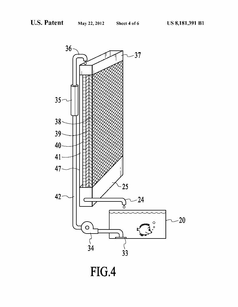
FIG. 4 is a detailed elevation vieW of a biological system for the hydroponic and aquaculture systems of a vertical aquaponic micro farm, according to an embodiment.
FIG. 5 is a schematic vieW of a hydroponic vertical garden and a bio-mat groW media system, under an embodiment.
FIG. 6 is a How diagram of process ?oWs in a ?shpond based a vertical aquaponic micro farm, according to an embodiment.
DETAILED DESCRIPTION
Embodiments of a vertical aquaponic micro farm are described. In the folloWing description, numerous speci?c details are introduced to provide a thorough understanding of, and enabling description for, embodiments of the system. One skilled in the relevant art, hoWever, Will recogniZe that these embodiments can be practiced Without one or more of the speci?c details, or With other components, systems, and so on. In other instances, Well-knoWn structures or operations are not shoWn, or are not described in detail, to avoid obscur ing aspects of the disclosed embodiments.
FIG. 1 is a ?rst perspective vieW of a vertical aquaponic micro farm, according to an embodiment. In one embodi ment, the vertical aquaponic micro farm comprises a scaf folding parabolic arch support structure With poWer systems, groW systems, and poWer storage/ management unit, and cer tain communications capabilities provided through a tele communication mast.
FIG. 1 illustrates a vertical aquaponic micro farm structure 9 under cultivation With actively groWing plants 31 groWing in or on a hydroponic garden bio media. Also shoWn as a groW product are ?sh Within ?sh pond 20 that may be coupled to the farm structure 9. The micro farm 9 essentially comprises a parabolic or other shape scaffolding 10 having attached tWo vertical masts 21 and 22 for supporting a Wind turbine 17, a telecommunication mast 18, and a Weather station 19. As shoWn, tWo sets of parabolic scaffolding structures are sepa rated by a certain distance and coupled together through a series of horizontal beams. The separation distance and the height of the scaffolding generally de?nes the siZe of the microfarm structure, and this can be set to many different dimensions, depending on needs and siZe constraints. A series of solar panels 16 and electrical storage bank 12 provide poWer for the ?sh pond pump and ultraviolet (UV) ?lter system. Details of the pump and ?lter system are shoWn more clearly in FIGS. 3 and 4, discussed in greater detail beloW.
The Weather station 19 can include one or more devices for measuring certain environmental conditions. These condi tions can include Wind speed, Wind direction, air temperature, humidity, barometric pres sure, and other relevant conditions. The telecommunications mast can support a radio antenna aerial, or other communications device, as Well as other sys tems, such as a GPS (global positioning system) device.
The micro farm system 10 incorporates a biologically active groW mat and ?lter system and combines a biological ?lter system With aquaculture and hydroponics technologies. Centrally positioned on the parabolic scaffolding 10 is a substantially vertical hydroponic plant groWing system. In
20
25
30
35
40
45
50
55
60
65
4 one embodiment, plants 31 are planted into a series of verti cally set, vegetable ?ber or food grade ?ber bio-mats, Which may additionally include activated carbon ?ltration mats. Alternatively the ?ber bio mat substrate may be replaced With stones, glass or brick fragments, or any combination thereof.
In a general implementation, Water is recycled through the groW media bed (bio-mat) and a biologic ?lter, Which can be inoculated With a culture of nitrifying bacteria in combination With the plant roots. For an embodiment in Which a ?sh pond is present, Water from the ?sh pond 20 is pumped out of the pond through an intake vent and then passed through the ultra violet ?lter for the purpose of sterilizing the Water from free ?oating bacteria, parasites, and algae, through a return pipe and into an upper irrigation reservoir. The Water ?oWs through an irrigation distribution head and sediment ?lter, Which evenly distributes Water and ?lters out large particu late, onto the top edge of the bio-mats. As shoWn in FIG. 1, the Water passes through three bio
mats that have been inoculated With bene?cial bacteria (e. g., Nitrosamines and Nitrobacteria) that convert ammonia into nitrite, and then nitrite into nitrate, so that plants 31 can metaboliZe. As the Water passes through the bio -mats, e?luent and nutrients are metaboliZed by the plant roots and the ben e?cial bacteria. The Water is collected in the irrigation catch ment trough 25, then returned to the ?sh pond 20 through the out?oW pipe 24. The Water is returned to the ?sh pond clear of materials harmful to the ?sh and at the same time provides a food source for the plants. The Water in system 9 is run on a closed, continuous recirculation loop.
FIG. 2 is a side pro?le elevation vieW of the vertical aqua ponic micro farm of FIG. 1.As shoWn in FIG. 2, the parabolic truss scaffolding 10 supports several system components and is provided in a shape and siZe appropriate for speci?c crop groWth and environmental conditions. In one embodiment, the scaffold structure 10 supports a Wind turbine 17 that produces electricity from Wind poWer. This poWer is sent to a voltage regulator 15 and then sent the electrical storage bank 12. The scaffold can also be con?gured to support one or more solar panels 16. The poWer generated from the Wind turbine 17 and solar panels 16 is stored in the electrical storage bank 12, Which can be a battery bank or similar storage unit (e. g., capacitor). The system can also be poWered by conventional AC poWer source Where available. The poWer is used upon demand by the recirculation pump and the ultra violet ?lter, and any other electrical device in the system. In one embodi ment, the scaffold structure 10 also supports a rock groW media 32.
FIG. 3 is a detailed rear elevation vieW of the scaffolding structure of FIG. 2. FIG. 3 shoWs in more detail, the con?gu ration and placement of the ?sh pond 20, electrical storage bank 12, poWer management circuits, recirculation pump housing 29, and other units of micro farm 9. Attached to the rear frame of the parabolic scaffolding through a mounting on the back brace is a poWer inverter and management unit 13, telecommunication system 14, voltage regulator 15, and a Weather station/anemometer 27. All electrical devices are Wired to the circuit breaker box 30 for poWer control. PoWer is supplied to and from the poWer sources and electrical devices to the storage bank 12 through poWer cable 49. The entire parabolic scaffolding may be set on a steel
foundation brace 26 for added stability. Alternatively, the scaffolding posts be set in concrete or equivalent foundations for permanent or semi-permanent deployment. In a further alternative embodiment, the scaffolding structure may be placed on Wheels or movable pallets for mobile or temporary deployments.

US 8,181,391 B1 5
As shown in FIG. 3, the ?sh pond 20 can include a guard or other type of lid 23 to prevent vermin from having access to the pond. A potting table 28 may also be provided Within the structure of scaffold 10.
FIG. 4 is a detailed elevation vieW of a biological system for the hydroponic and aquaculture system, under an embodi ment. FIG. 4 also provides a diagram of a recirculation ?oW chart, according to the operation of the micro farm system. As shoWn in FIG. 4, ?sh, Which may be used as a human food source, are raised in the ?sh pond 20. The Water in the ?sh pond collects Waste from the ?sh, dead plants, uneaten ?sh food, and other biological residue. These are passed as part of the nutrient load in the Water incorporating ammonia, nitrites, nitrates, and nitrogen. The Water and both soluble and solid Wastes are sucked up from the ?oor of the ?sh pond 20 and recycled through a biological ?lter system. In embodiment, the biological ?lter system comprises a set of bio-mats 38, 39, and 40 on Which plants are groWn. The Water ?oWs doWn through the set ofbio-mats 38, 39, and 40, Which can be mats comprised of vegetable ?bers and activated carbon. The bio mats have are inoculated With the bene?cial bacteria and nutrients (e.g., nitrobacteria and nitrosamines) for the pur pose of breaking doWn the ammonia and nitrite load in the Water and converting components in the e?luent into nitrate, a plant food.
For the system of FIG. 4, Water is taken from ?sh pond 20 through a pond Water intake vent 33 by recirculation pump 34. The Water is fed through tube 42 Which comprises the plumb ing for the irrigation system to an ultra violet ?lter/steriliza tion unit 35. The Water is then fed out ofWater return pipe 36 through an upper irrigation reservoir 37. The Water then passes through vegetable ?ber bio-mat 38, secondary veg etable ?ber bio-mat 39, and activated carbon ?lter 40. The Water then ?oWs through irrigation catchment trough and out of the out?oW pipe 24 back into the ?sh pond 20.
The bio-mat and ?lter system 38, 39, and 40 are illustrated as three separate mat like components of the same siZe deployed in a sandWich array. It should be noted, hoWever, that this ?lter and plant substrate system can be composed of mats and/or ?lters of any appropriate siZe, shape and material depending upon con?guration and needs. For example, any practical number of bio-mats (e. g., 1-4) may be used, and the ?lter 40 may be separate or integrated Within the one or more mats. As shoWn in FIG. 4, the bio-mat and ?lter structure is disposed proximate to an area 41, Which represents space for the plant roots. The embodiment of FIG. 4 also shoWs a Wall garden housing 47 for deployment of the bio-mat/ ?lter struc ture in a vertical orientation as mounted on a Wall, hanging from a frame, or mounted on a scaffold structure, as shoWn in FIG. 1.
FIG. 5 is a schematic vieW of a hydroponic vertical garden and a bio -mat groW media system, under an embodiment. As shoWn in FIG. 5, a plant 45 is planted substantially perpen dicularly into the vegetable ?ber or food grade plastic mats 38 and 39. The plant is held in place by the ?rst bio-mat 38 and the roots pass through and groW through the second bio-mat 39 and continue groWing into the third bio-mat 40, Which may be an activated carbon ?lter or additional bio-mat layer. The bio-mat/?lter assembly is held in place by a bio-mat holder frame 48. The activated carbon ?lter 40 helps ?lter the Water supply, adds a carbon nutrient for the plant roots and provides a surface area for microorganism colonies that aids in the bio digestion of the nitrogen load in the Water supply and helps With ?ltering hydrocarbons from the air that are breathed in through the plants leaves and xylem by the photosynthesis and evapo-transpiration cycle. After passing through the bio mat/?lter structure and the plant roots 46, the Water is col
20
25
30
35
40
45
50
55
60
65
6 lected in the irrigation catchment trough 25 and passed back to the ?sh pond 20, through the out?oW pipe 24. The recircu lation pump 35 in trough 25 pumps the Water back up plumb ing to continue the Water cycle in a closed loop. In an embodi ment, Water from the out?oW pipe 24 is passed through an irrigation distribution head and sediment ?lter 44 Which is disposed Within an upper irrigation reservoir 37.
FIG. 6 is a How diagram of process ?oWs in a ?shpond based a vertical aquaponic micro farm, according to an embodiment. The How diagram illustrates the closed-loop process of How betWeen the ?sh pond 62 and vertical hydro ponic garden 64. In this process How, Water is pumped from ?sh pond 64 through pump 66 to a biological ?lter 68. The Water is then passed to a settling tank and pump 70 through an ultraviolet light 72. Water from the vertical hydroponic gar den 62 also passes through ultraviolet light 72 and to the ?sh pond 62.
The vertical aquaponic garden alloWs a form of farming or gardening that is suitable for virtually any siZe ?at or vertical surface. The biological systems can be mounted on a para bolic or other shape scaffolding 10 for better placement of components and to support an aquaponic food production system 9. For example, the parabolic scaffolding could be a square scaffolding support structure or a dome shaped scaf folding structure. Alternatively, no scaffolding may be used and the system may instead be ?at mounted on a vertical (Wall) or horizontal (ground) surface. Thus, the biological recirculation system can be Wall mounted, as shoWn in FIG. 5 With Wall mounting housing 47. For ?at farming options, the housing 47 can be placed horizontally rather than vertically and run on a hydroponic groWing system. The scaffolding can be designed as a parabolic arch shaped
structure, or any similar shape that is suitable to position the bio-mats in a vertical orientation, or at any angle desired. The scaffolding may be made of any number of materials, such as steel, aluminum, plastic, Wood, bamboo, and carbon ?ber, or any other suitable material depending upon cost, location, and environmental factors.
Other alternative embodiments of the vertical aquaponic micro farm are possible. For example, it is possible to run the vertical garden system Without the aquaculture component FIG. 5. In the absence of the aquaculture component, nutri ents and microorganisms can be added to the Water system 37 by pouring a mixture of nutrients and microorganisms directly into the Water supply or the irrigation catchment trough 25, as needed. The bio-mats 38 and 39 could be built from many different
?ber materials and mesh designs. The bio-mat structures can comprise baskets of stone, glass, charcoal or other locally available substrates. Embodiments include one or more electrical circuits, but
are not so limited. Such embodiments can be poWered by many different poWer sources, including Wind, solar, AC poWer, fuel cell systems, internal combustion engines, human poWered generators, and so on. Wind poWer can be provided by a Wind turbine 17 mounted on a mast 21 directly connected to the scaffold structure 10, or any similar fan or prop that can be used to harness Wind poWer. The system can be installed indoors With the addition of an
appropriate light system or out doors With natural sun light. The bio-mats can be seeded directly as is conventionally done With soil-based plants. The bio-mat system can also be pre seeded, sprouted andplaced into a vertical garden, as seasonal conditions permit. The system may include certain environment monitoring
devices to optimiZe deployment in certain regions and con ditions. These can include a Wind speed gauge 19 and certain

US 8,181,391 B1 7
Weather station devices or radio aerials provided on a tele communication mast 18, and or a mast 22. An embodiment is directed to an apparatus comprising a
support structure, a plurality of bio-mats placed on the sup port structure in a substantially vertical orientation, the bio mats supporting the growth of one or more varieties of plants, a Water source coupled to the bio-mats through a pump and plumbing system, Wherein the plumbing system is con?gured to draW Water from the Water source through the bio-mats and back to the Water source in substantially closed loop aquatic system, and one or more poWer generation components pro viding electrical energy to the pump and plumbing system. The apparatus of claim 1 Wherein the support structure is a parabolic arch support structure. The parabolic arch support structure may comprise tWo sets of interlinked scaffolds coupled to each other by a plurality of horizontally disposed beams, and the support structure may be constructed of a material such as steel, aluminum, plastic, Wood, bamboo, or carbon ?ber.
In an embodiment, the bio-mats are inoculated With ben e?cial bacteria to convert ammonia into nitrite, and then convert the nitrite into nitrate to alloW plants seeded thereon to metaboliZe. The apparatus may further have an irrigation catchment trough to collect Water passing through the biom ats for return to the Water source. The Water source can be a
?sh pond including one or more live ?sh. The Water provided to the plants contains impurities and nutrients from the ?sh pond, and the plumbing includes one or more ?lter compo nents to ?lter the Water from the biomats to provide Water back to the ?sh pond clear of materials harmful to the ?sh. At least some of the ?lter components can be in the form of a biomats, and the biomats may consist of a material such as a ?brous mesh material, and a basket of stone, glass or char coal. A guard structure may be placed over the ?sh pond to prevent intrusion by vermin and pests.
The apparatus can include a Weather station mounted on a
mast coupled to the support structure, With the Weather station including devices for measuring certain environmental con ditions such as Wind speed, Wind direction, air temperature, barometric pressure, and humidity. A radio system or antenna may be mounted on a second mast coupled to the support structure. The poWer generation components can include Wind turbines, Water turbines, solar panels, AC electrical poWer, human-poWered generators, batteries, and fuel cells.
Embodiments are also directed to a closed-loop aquatic and closed-loop electrical system for groWing plants com prising: a support structure, a plurality of bio-mats placed on the support structure in a substantially vertical orientation, the bio-mats supporting the groWth of one or more varieties of plants, a Water source coupled to the bio-mats through a pump and plumbing system, Wherein the plumbing system is con ?gured to draW Water from the Water source through the bio-mats and back to the Water source in substantially closed loop aquatic system, and one or more poWer generation com ponents generating poWer from non-electrical grid-based poWer sources, and a poWer storage system storing poWer generated by the poWer generation components and providing electrical energy to the pump and plumbing system to provide poWer in a substantially closed-loop electrical system. In this system, the plumbing system comprises one or more Water pumps and ?lters, and the poWer generation circuits may include Wind turbines, Water turbines, solar panels, and human-poWered generators.
Independent of any particular structure, embodiments are also directed to a method of groWing plants comprising: pro viding a plurality of biomats in a substantially vertical orien tation relative to the ground, seeding the biomats With plant
20
25
30
35
40
45
50
55
60
65
8 matter, providing a Water source coupled to the biomats through a pump and plumbing system, the Water source including Water enriched With nutrients and impurities, pumping enriched Water through the biomats from the Water source, ?ltering the enriched Water from the biomats to pro duce clean Water, and returning the clean Water to the Water source in a substantially closed-loop aquatic system.
Unless the context clearly requires otherwise, throughout the description and the claims, the Words “comprise,” “com prising,” and the like are to be construed in an inclusive sense as opposed to an exclusive or exhaustive sense; that is to say, in a sense of “including, but not limited to.” Words using the singular or plural number also include the plural or singular number respectively. Additionally, the Words “herein,” “here under,” “above,” “beloW,” and Words of similar import refer to this application as a Whole and not to any particular portions of this application. When the Word “or” is used in reference to a list of tWo or more items, that Word covers all of the folloW ing interpretations of the Word: any of the items in the list, all of the items in the list and any combination of the items in the list. The above description of illustrated embodiments of the
vertical aquaponic micro garden is not intended to be exhaus tive or to limit the embodiments to the precise form or struc tures disclosed. While speci?c embodiments of, and examples for, the micro farm are described herein for illus trative purposes, various equivalent modi?cations are pos sible Within the scope of the described embodiments, as those skilled in the relevant art Will recogniZe. The elements and acts of the various embodiments
described above can be combined to provide further embodi ments. These and other changes can be made to the location based social netWork manager process in light of the above detailed description.
In general, in any folloWing claims, the terms used should not be construed to limit the described system to the speci?c embodiments disclosed in the speci?cation and the claims, but should be construed to include all operations or processes that operate under the claims. Accordingly, the described system is not limited by the disclosure, but instead the scope of the recited method is to be determined entirely by the claims.
While certain aspects of the vertical aquaponic micro farm, according to an embodiment are presented beloW in certain claim forms, the inventor contemplates the various aspects of the methodology in any number of claim forms. Accordingly, the inventor reserves the right to add additional claims after ?ling the application to pursue such additional claim forms for other aspects of the described systems and methods.
What is claimed is: 1. An apparatus comprising: a support structure is a parabolic arch support structure
comprises a truss-based structure having tWo sets of interlinked scaffolds coupled to each other by a plurality of horizontally disposed beams;
a plurality of bio-mats placed on the support structure in a substantially vertical orientation, the bio-mats support ing the groWth of one or more varieties of plants, Wherein each bio-mat of the plurality of bio-mats com prises a composite layered assembly including a ?rst vegetable ?ber mat layer, a second vegetable ?ber mat layer and an activated carbon ?lter layer Wherein the plurality of bio-mats are arranged along a bottom por tion of the support structure;
a Water distribution system arranged along an upper por tion of the support structure and con?gured to How Water

US 8,181,391 B1 9
to the bio-mats back to a Water source placed adjacent the support structure to form a substantially closed loop aquatic system; and
one or more poWer generation components providing elec trical energy the Water distribution system.
2. The apparatus of claim 1 further comprising one or more solar panels coupled to the one or more poWer generation components are arranged along an upper portion of the sup port structure.
3. The apparatus of claim 1 Wherein the support structure is constructed of a material selected from the group consisting of: steel, aluminum, plastic, Wood, bamboo, and carbon ?ber.
4. The apparatus of claim 1 Wherein the bio-mats are inocu lated With bene?cial bacteria to convert ammonia into nitrite, and then convert the nitrite into nitrate to alloW plants seeded thereon to metaboliZe.
5. The apparatus of claim 4 further comprising an irrigation catchment trough to collect Water passing through the biom ats for return to the Water source and further comprising a pump and plumbing system, Wherein the plumbing system is con?gured to draW Water from the Water source for distribu tion through the plurality of bio-mats.
6. The apparatus of claim 5 Wherein the Water source com prises a ?sh pond including one or more live ?sh.
7. The apparatus of claim 6 Wherein the Water provided to the plants contains impurities and nutrients from the ?sh pond, and Wherein the plumbing includes one or more ?lter components to ?lter the Water from the biomats to provide Water back to the ?sh pond clear of materials harmful to the ?sh.
8. The apparatus of claim 7 Wherein at least some of the ?lter components comprise one or more of the biomats, and Wherein the biomats consist of a material selected from the group consisting of a ?brous mesh material, and a basket of stone, glass or charcoal.
9. The apparatus of claim 8 further comprising a guard structure placed over the ?sh pond to prevent intrusion by vermin and pests.
10. The apparatus of claim 8 further comprising an ultra violet ?lter system.
11. The apparatus of claim 1 further comprising: a Weather station mounted on a ?rst mast coupled to the
support structure, Wherein the Weather station includes devices for measuring certain environmental conditions selected from the group consisting of: Wind speed, Wind direction, air temperature, barometric pressure, and humidity; and
20
25
30
35
40
45
10 a radio system mounted on a second mast coupled to the
support structure. 12. The apparatus of claim 1 Wherein the poWer generation
components are selected from the group consisting of: Wind turbines, Water turbines, solar panels, AC electrical poWer, human-poWered generators, batteries, and fuel cells.
13. The apparatus of claim 1 further comprising a base coupled to the support structure to alloW free standing of the support structure on a substantially horiZontal surface.
14. The apparatus of claim 1 further comprising a vertical mounting component coupled to the support structure to alloW mounting of the support structure on a substantially vertical surface.
15. A closed-loop aquatic and electrical system for groW ing plants comprising:
a truss-based scaffolding support structure is a parabolic arch support structure comprises tWo sets of interlinked scaffolds coupled to each other by a plurality of hori Zontally disposed beams;
a plurality of bio-mats placed on the support structure in a substantially vertical orientation, the bio-mats support ing the groWth of one or more varieties of plants, Wherein each bio-mat of the plurality of bio-mats com prises a composite layered assembly including a ?rst vegetable ?ber mat layer, a second vegetable ?ber mat layer and an activated carbon ?lter layer Wherein the plurality of bio-mats are arranged along a bottom por tion of the support structure;
a Water distribution system arranged along an upper por tion of the support structure and con?gured to How Water to the bio-mats back to a Water source placed adjacent the support structure to form a substantially closed loop aquatic system; and
one or more poWer generation components generating poWer from non-electrical grid-based poWer sources; and
a poWer storage system storing poWer generated by the poWer generation components and providing electrical energy the Water distribution system to provide poWer in a substantially closed-loop electrical system.
16. The system of claim 15 further comprising a plumbing system having one or more Water pumps and ?lters, and the poWer generation circuits are selected from the group con sisting of: Wind turbines, Water turbines, solar panels, and human-poWered generators.
* * * * *


![[en-us] bosch-home.com/us/mybosch mybosch [en-us] Dishwasher](https://img.pdfslide.us/doc/110x75/615cc8afbe7e0d1e5a38c77e/en-us-bosch-homecomusmybosch-mybosch-en-us-dishwasher.jpg)

