Embed Size (px)
Citation preview
11 Sheets—-Sheet 2-.
J. GARPENTIER.
MBGHANIOAL KEY BOARD PLAYER.
(No Model.)
No. 371,422. atente'd oct. 11, 1887.
\ E
.ENQQM N $
_ E
Q m
W
W A
x. ‘vans. m W 1. Wm no.
11 Sheets-Sheet 3. (No Model.)
J. GARPENTIER. MECHANICAL KEY BOARD PLAYER.’
No. 371,422. Patented Oct. 11,1887.
z
xxx _
%
5
INVENTOR: '
ZZT NESSES- v
%M
(No Model.) 11 Sheets-Sheet 4.
J. GAR‘PENTIER. MECHANICAL KEY BOARD PLAYER.
No. 371,422. ' .N Patented Oct. 11,1887.
0 . |
-<_-_ INVENTOR‘. WITNESSE ; “ ' m (9 mm’ d” ' 3*— iiLP?
/6 t I ’ L'y hi6 Jttom-ays,
N. PETERS. Pmnmwgnym. Walhin?an, D. C.
(N0 Modél.) 11 Sheets-Sheet 5.
J. OARPENTIER. MECHANICAL KEY BOARD PLAYER.
No. 371,422. <_'~* Patented Oct. 11 1887.
I’ (25)
N‘ PETERS, Photo-l-ilhcgnphur. Wa‘hingwn. D4 0.
(No Model.) 11 Sheets—Sheet 7.
vJ. OARPENTIER. MEOHANIGAL KEY BOARD PLAYER.
No. 371,422. Patented Oct. 11,1887.
l
i A i
{@- ‘léi' -
. _ | - _ _
WITNESSE ’ _ I \ cm @‘mmm @
Who/7C WWW ‘
N. rnzns, Pholn-Lilhognpiwr. WalMnghm, B4 c.
7 (No Model.) 11 Sheets-Sheet 8..
J. OARPENTIER. '
MECHANICAL KEY BOARD PLAYER.
No. 371,422. P tent d O t. 11,,188'7. a. L 0
I l
I l I | | l T l X
"\ \
\ \
l
607W.
TWENTOTR';
lTNEssg; +,- 5% @329 %V .' ' N {5,3 ‘6V3: $110M,
. Wgim y@
N. PETERS, Phoh-UlMg/aphlr. Walhingtau. 11c.
(No Model.) ‘ 11 Sheets—-Sheet '10. ‘
J. GARPBNTIER. MECHANICAL KEY BOARD PLAYER.
No. 371,422. - Patented Oct. 11,1887.
‘ INVENTOR:
WITNESSEg: Mi gym W , ' , By his Az‘forlzeys, -
y/m/wwmmi wrj?
n. mzns mum-m wmm. 0.0.
(No Model.) I I ll Sheets-—Sheet 11.
'J. GARPENTIER. ‘ I MECHANICAL KEY BOARD PLAYER. I
No. 371,422. r ' Patented Oct. 11,1887.
22¢ 741. 7,3. 7)“ ‘
Fay.”
'IgIflEZ-Zifiiél'. ‘ I
INVENTOR:
WITNESSES' ‘ ' bi? gaping‘ ' '
. ' , ‘ By Aw Attorneys,
N. mills. MLhho'I-lphu, WM", 1:, c.
[5
20
35
45
50
UNITED STATES PATENT OFFICE.
JULES UARPENTIER, OF PARIS, FRANCE.
MECHANICAL KEY-BOARD PLAYER.
SPECIFICATION forming part of Letters Patent Nov 371,422, dated @ctober 11, 1887.
Application ?led May 28, 1857. Serial No. 239,655. (No model.) Patented in France October 31, 1884, No. 165.133; in England June 10, 1885, No. 7,096; in Belgium June 12, 1885. No. 69,244; in Germany June 23, i885. No. 34,191, and in Austria-Hungary October '
27, 1885, No. 21,869 and No. 51.02;‘,
T0 aZZ whom. it may concern. Be it known that l, JULEs CARPENTIER, a
citizen of the French Republic, residing in Paris, France, have invented certain new and useful Improvements in Apparatus for Me chanically Playing Keyed Musical Instru ments, of which the following is a specifica tion. '
This invention is the subject of a patent in France, dated October 31', 1884. No. 165,133; in England, dated June 10, 1885, No. 7,096; in Belgium, dated June 12, 1885, No. 69,244, in Germany, dated June 23, 1885, No. 31,191, and in AustriaHungary, dated September 27, 1885, No. 24,869 and No. 51,022. ' My invention provides an apparatus which
I call a “melotrope,” for actuating a piano, organ, or any other keyed instrument accord ing to the perforations in a prepared band of paper. This apparatus, on being mounted over the keyboard of the piano or other in strument and rotated by means of a crank or otherwise, depresses the keys of the instru ment automatically and in the order and time determined by the perforations in the band of paper. My improved apparatus for this purpose
operates on the principle of the pressing down or displacement of moving parts, which cor respond in position to the keys of the instru ment which is to be actuated, by means of the friction of a cord or hand against a continu ously-rotated part, upon the cord or band be ing engaged with or disengaged from said ro tating part by mechanism under the control of the perforations in the prepared band of paper. By this means the keys are depressed with a sufficient force derived from the rotat ing part and entirely independent of the force exerted by the perforated paper in its passage through the apparatus. My inelotrope includes two essential parts-
the one which I call the “servo-motor” is de signed to transmit to the different keys of the instrument the pressure transmitted to the crank or other source of power, and the other, which I call the “reader,” is acted upon by the band of perforated paper, and serves to throw into and out of gear with the rotating cylinder the cords which put in motion the
l several plungers by which the keys of the in~ strumcnt are depressed. The accompanying drawings represent a
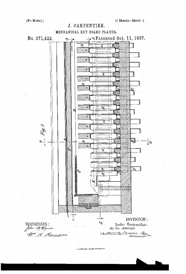
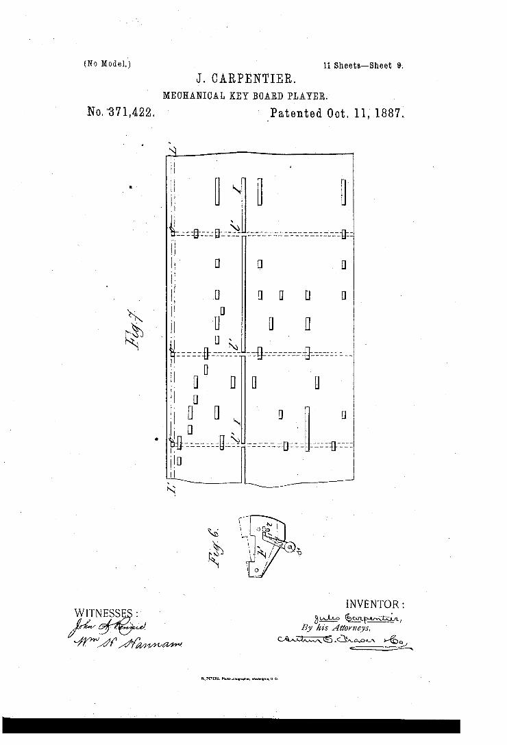
melotrope designed for thirtyseven notes. Figure 1 is a longitudinal vertical section
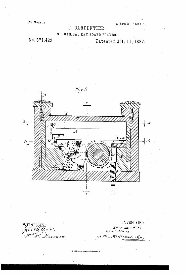
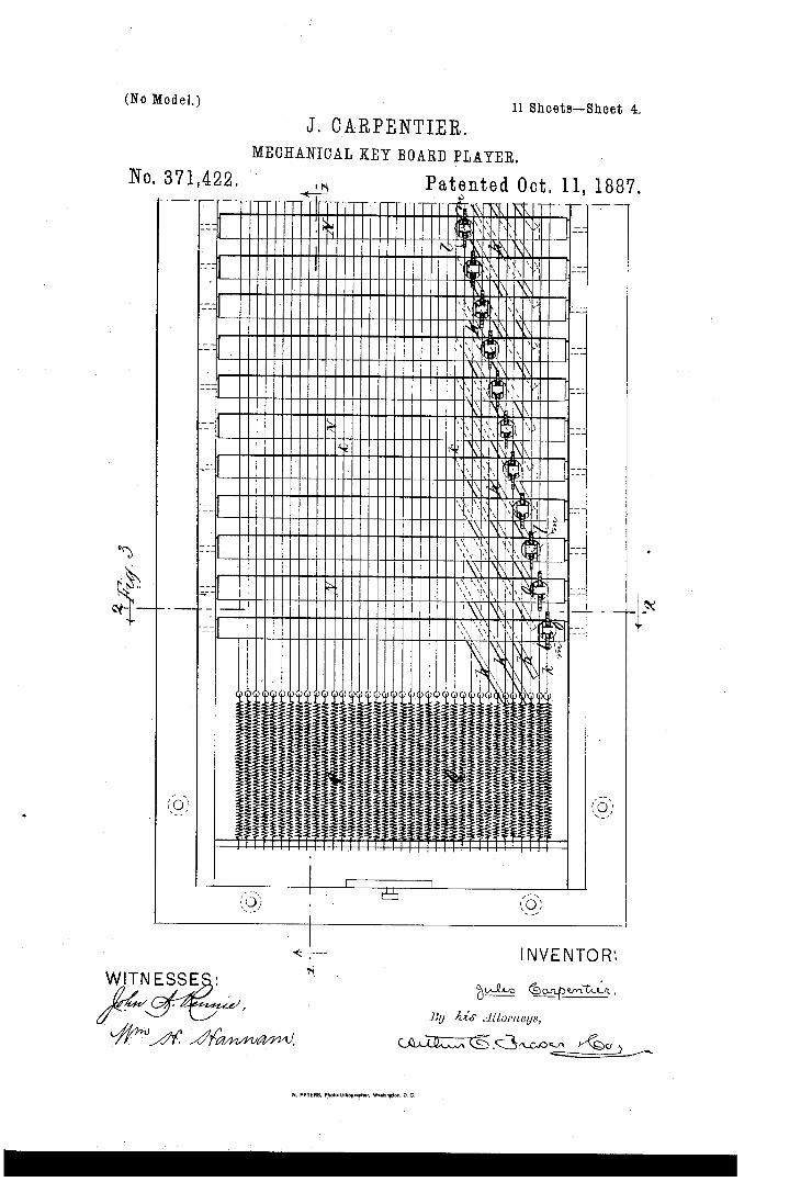
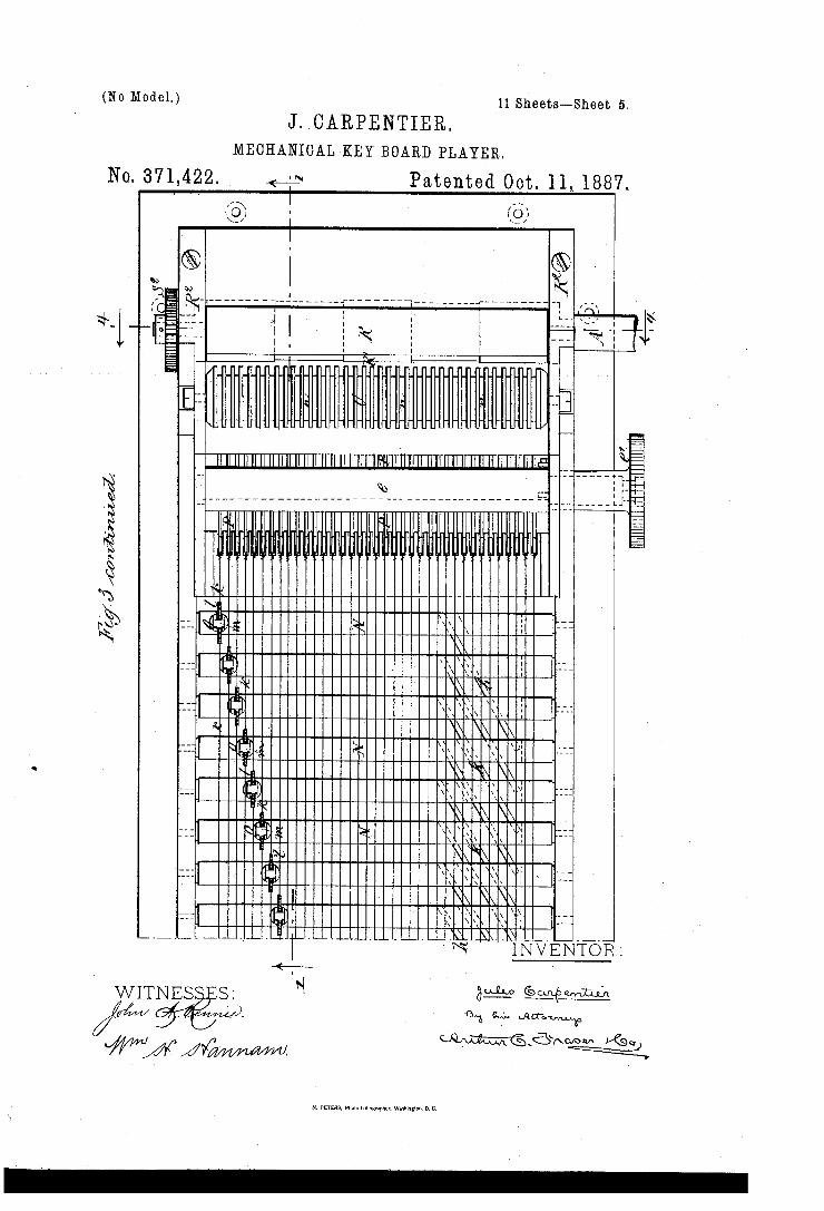
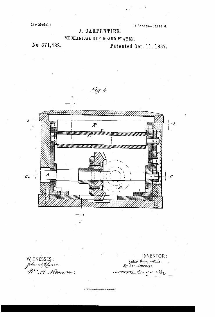
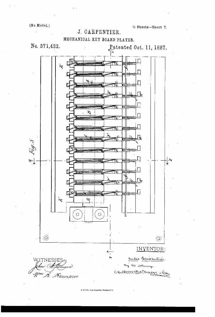
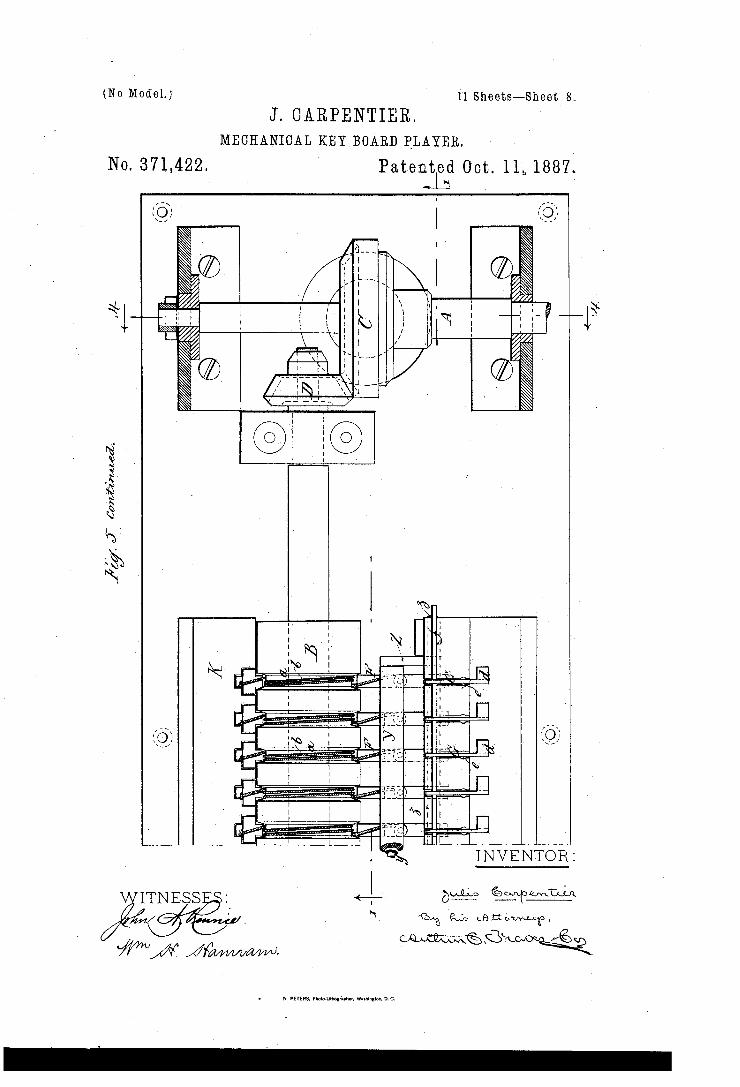
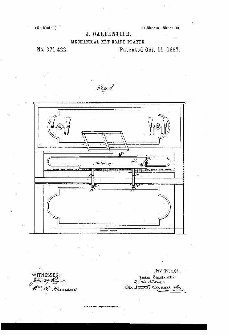
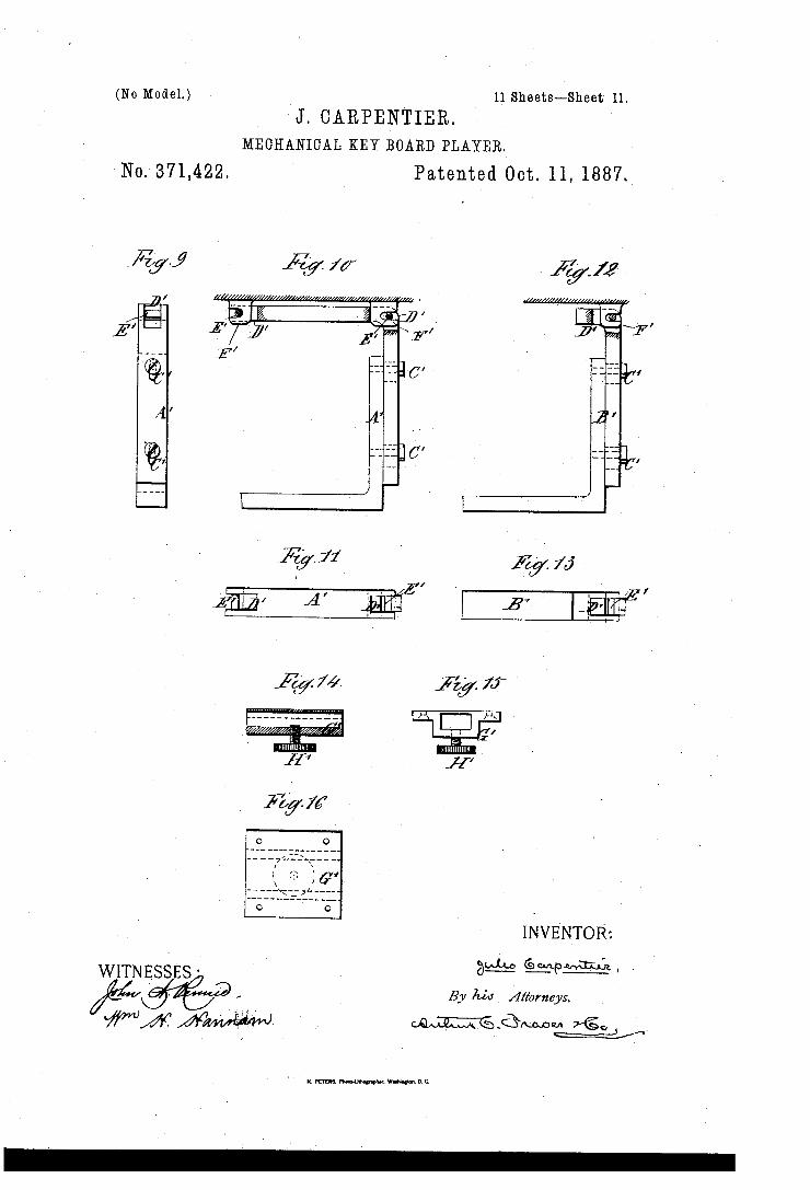
thereof cut. in the plane of the lines 1_ 1 in Figs. 2 and 4. Fig. 2 is a vertical transverse sec tion thereof cut in the plane of the line 2 2 in Figs. 1 and 5. Fig. 3 is aplan with the cover removed. Fig. 4 is a transverse section cut in the plane of the line 4 4 in Fig. 1. Fig. 5 is a plan of the servo motor in place on the bottom of the inclosing case, the sides of the latter having been removed. Fig. 6 is a de tail view looking in the same direction as Fig. 2. Fig. 7 is a plan of the perforated band of paper. Fig. 8 is a front elevation of an up right piano or organ to which my invention is applied. Figs. 9 to 16, inclusive, are detail views illustrating the means for mounting the melotrope on the piano or organ.
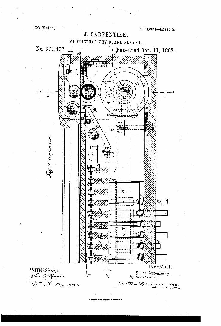
Referring first to Figs. 1 to 5, let A desig nate the driving shaft, which is rotated by a crank or other motor; B, a rotary cylinder extending longitudinally of the apparatus, and O and D bevel-wheels fixed on the respect ive shafts by which the cylinder B is driven from the shaft A. The cylinder B is formed with as many pc
ripheral grooves c a, having their sides slightly coned, as there are notes to be played by the apparatus. In each groove a is arranged a cord, Z),which makes two or three turns around it, and one end of which is ?xed to a pusher bar or plunger, E, while its other end is fixed by means of alitt-le clamp-screw, c, to awooden sector, F. By turning the screw 0 the cord may be adjusted to the proper tension. The several plungers E E are spaced apart to the same width as the keys of the piano to be played upon, and their ends project down and are normally in contact with the keys. The sector F is fulcrumed at the end of a
vertical arm of an elbow-lever, G, which is pivoted at fand the horizontal arm of which terminates in a flat head, (Z, and is kept pressed upward by a little spring, 6. The curved por tion of the sector F projects slightly within the groove a, but does not touch the sides thereof when in repose.
55
65
70.
85
95
IO
_ of the piano and press it down.
IO LA
33
35
40
45
3
2' 371,422
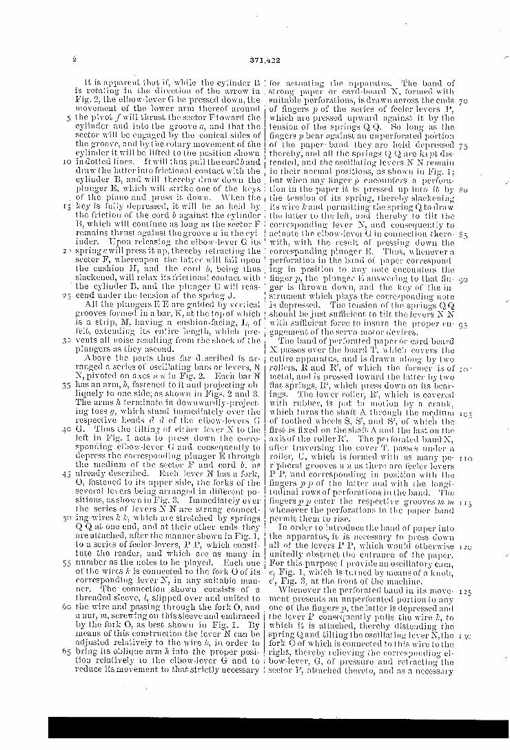
It is apparent that if, while the cylinder 13 is rotating in the direction of the arrow in Fig. 2, the elbow-lever G be pressed down, the movement of the lower arm thereof around the pivot f will thrust the sector Ftoward the cylinder and into the groove (1, and that the sector will be engaged by the conical sides of the groove, and by the rotary movement of the cylinder it will be lifted to the position shown in dotted lines. Itwill thus pull the cord band draw the latterintofrictional contact with the cylinder B, and will thereby draw' down the plunger 1'], which will strike one of the keys
\Vhcn the key is fully depressed, it will be so held by the friction of the cord 1) against the cylinder 13, which will continue as long as the sector F remains thrust against the groove a in the cyl inder. Upon releasing the elbow-lever G its springc will press it up, thereby retracting the sector F, whereupon the latter will fall upon the cushion H, and the cord 2), being thus slackened, will relax its frictional contact with the cylinder 13, and the plunger IE will reas eend under the tension of the spring J. All the plungcrs E E are guided by vertical
grooves formed in a bar, K, at the top of which is a strip, M, having a cushion-facing, L, of felt, extending its entire length, which pre vents all noise resulting from the shock of the plnngers as they ascend. Above the parts thus far (ltSCl'lbCd is ar
ranged a series of oscillating bars or levers, N N, pivoted on axes a a in Fig. 2. Each bat-N has an arm, 71., fastened to it and projecting ob
liquely to one side, as shown in Figs. 2 and The arms h terminate in downwardly-project
ing toes _(/, which stand immediately over the respective heads (1 d of the elbow-levers G G. Thus the tilting of either lever N to the left in Fig. 1 acts to press down the corre sponding elbow-lever (l and consequently to depress the corresponding plunger E through the medium of the sector F and cord b, as already described. Each lever N has a fork, O, fastened to its upper side, the forks of the several levers being arranged in different po sitions, as shown in Fig. 3. Immediately over the series of levers N N are strung connect ing-wires 7s 7.‘, which are stretched by springs Q, Q at one end, and at their other ends they .are attached, after the manner shown in Fig. 1, to a series of fceler-levers, P P, which consti~ tute the reader, and which are as many in number as the notes to be played. Each one of the wires k is connected to the fork O of its corresponding lever N, in any suitable man
Y ner. The connection shown consists of a threaded sleeve, Z, slipped over and united to the wire and passing through the fork O, and a nut, m, screwing on this sleeve and embraced by the fork O, as best shown in Fig. 1. By means of this construction the lever N can be adjusted relatively to the wire 7;, in order to bring its oblique arm 71 into the proper posi tion relatively to the elbow-lever G and to reduce its movement to that strictly necessary
for actuating the apparatus. The band of strong paper or card-board X, formed with suitable perforations, is drawn across the ends of ?ngers p of the series of feelerlcvers 1), which are pressed upward against it by the tension of the springs Q Q. So long as the ?ngers 1) bear against an unperforated portion of the paperband they are held depressed thereby, and all the springs Q Q are kept dis tended, and the oscillating levers N N remain in their normal positions, as shown in Fig. 1; but when any linger p encounters a perfora tion in the paper it is pressed up into it by the tension of its spring, thereby slackening its wire 7t and permitting the spring Q to draw the latter to the left, and thereby to tilt the corresponding lever N, and consequently to actuate the elbow-lever G in connection there7 with, with the result of pressing down the corresponding plunger ll}. Thus, whenever a perforation in the band of paper correspond ing in position to any note encounlers the lingerrp, the plunger E answering to that fin ger is thrown down, and the key of the in strument which plays the corresponding note is depressed. The tension of the springs QQ should bejust sufficient to tilt the lovers N N with sufficient force to insure the proper in gagement ol' the servo-motor devices. The band of perforated paper or cardboard
X passes over the board T, which covers the entire apparati'is. and is drawn along by two rollers, t and R’, of which the former is of metal, and is pressed toward the latter by two flat springs, E, which press down on its bear‘ ings. The lower roller, R’, which is covered with rubber, is put in motion by a crank, which turns the shaft A through the medium of toothed wheels S, S’, and S2, of which the first is ?xed on the shaft A and the last on the axisof the roller'lt’. The perforated bandX, after traversing the cover '1‘. passes under a roller, U, which is formed with as many pe ripheral grooves n n. as there are l'eelcr levers P P, ‘and corresponding in position with the fingers pp of the latter and with the lOllgl tudinal rows of perforations in the band. The ?ngers p p enter the respective grooves in in. whenever the perforations in the paper band permit them to rise.
In order to introducclhe band of paper into the apparatus, it is necessary to press down all of the levers l’ P, which would otherwise unitedly obstruct the entrance of. the paper. For this purpose I provide an oscillatory cam, c, Fig. 1, which is turned by means of a knob, 0', Fig. 3, at the front of the machine. XVhenever the perforated band in its move
ment presents an unperforatcd portion to any one of the fingers p, the latter is depressed and the lever I) consequently pulls the wire Zr, to which it is attached, thereby distending the spring Q and tilting the oscillating lever N,the fork O of which is connected to this wire to the right, thereby relieving the corresponding el bow-lever, G, of pressure and retracting the sector F, attached thereto, and as a necessary
70
80
I10
115
15
25
35
45
_ provided for preventing this effect.
371,422
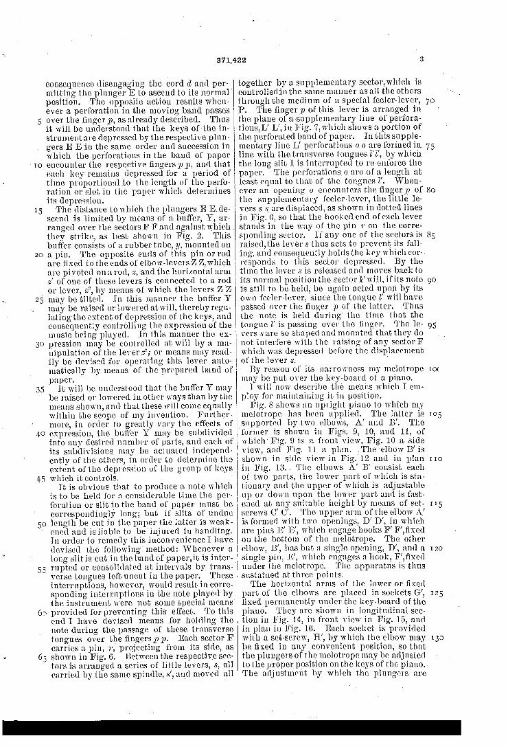
consequence disengaging the cord (1 and per mitting the plunger E to ascend to its normal position. The opposite action results when ever a perforation in the moving band passes over the ?nger p, as already described. Thus it will be understood that the keys ofthe in strument are depressed by the respective plun gers E E in the same order and succession in which the perforations in the band of paper encounter the respective ?ngers pp, and that each key remains depressed for a period of time proportional to the length of the perfo ration or slot in the paper which determines its depression. _ The distance to which the plungers E Ede
scend is limited by means of a buffer, Y, ar ranged over the sectors F F and against which . they strike, as best shown in Fig. 2. This buffer consists of a rubber tube, 1/. mounted on a pin.' The opposite ends of this pin or rod are ?xed to the ends of elbow-levers Z Z, which are pivoted on a rod, 2, and the horizontal arm 2’ of one of these levers is connected to a rod or lever, 22, by means of which the levers Z Z may be tilted. In this manner the buffer Y may be raised orlowered atwill, thereby regu lating the extent of depression of the keys, and consequently controlling the expression of the music being played. In this manner the ex pression may be controlled at will by a ma nipulation of the lever 52; or means may read ily be devised for operating this lever auto matically by means of the prepared band of paper.
It will be understood that the buffer Y may be raised or lowered in other ways than by the means shown, and that these will come equally within the scope of my invention. Further more, in order to greatly vary the effects of expression, the buffer Y .may be subdivided into any desired number of parts, and each of its subdivisions may be actuated iudepend' ently of the others, in order to determine the extent of the depression of the group of keys which it controls. ‘
It is obvious that to produce a note which is to be held for a considerable time the per~ foration or slit in the band of paper must be correspondingly long; but if slits of undue length be cut in the paper the latter is weak ened and is liable to be injured in handling. In order to remedy this inconvenience I have devised the following method: IVhcnever a long slit is cut in the band of paper,it is inter rupted or consolidated at intervals by trans verse tongues left uncut in the paper. These interruptions, however, would result in corre sponding interruptions in the note played by the instrument were not some special means
To this end I have devised means for holding the note during the passage of these transverse tongues over the ?ngers p 1). Each sector F carries a pin, 7‘, projecting from its side, as shown in Fig. 6. Between the respective sec tors is arranged a series of little levers, s, all carried by the same‘spindle, s’, and moved all
together by a supplementary sector,which is controlled in the same manner as all the others through the medium of a special feeler-lever, P. The ?nger p of this lever is arranged in the plane of a supplementary line of perfora~ tions,L’ L’, in Fig. 7,which shows a portion of the perforated band of paper. In this supple mentary line L’ perforations o 0 are formed in line with the transverse tongues Z’ Z’, by which the long slit I is interrupted to re-enforce the paper. The perforations 0 are of a length at least equal to that of the tongues Z’. VVhen ever an opening 0 encounters the ?nger p of the supplementary feeler-lever, the little le vers s s_ are displaced, as shown in dotted lines in Fig. 6, so that the hooked end ofeach lever stands in the way of the pin r on the corre sponding sector. If any one of the sectors is raised,the lever 8 thus acts to prevent its fall ing, and consequently holds the key which cor~ responds to this sector depressed. By the time the lever s is released and moves back to its normal position the sector Fwill, ifits note is still to be held, be again acted upon by its own feeler-lever, since the tongue vZ’ will have passed over the ?nger p of the latter. Thus the note is held during‘ the time that the tongue Z’ is passing over the finger. The le< vers s are so shaped and mounted that they do not interfere with the raising of any sectorF which was depressed before the displacement of the lever s. ' By reason of its narrowness my melotrope
may be put over the key-board of a piano. 1 will now describe the means which I em
ploy for maintaining it in position. Fig. 8 shows an upright piano to which my
melotrope has been applied. The latter is supported by two elbows, A’ and B’. The vformer is shown in Figs. 9, l0, and 11, of which‘ Fig. 9 is a front view, Fig. 10 a side view, and Fig. 11 a plan. The elbow B’ is shown in side viewiu Fig/12 and in plan in Fig. 13.. The elbows A’ B’ consist each of two parts, the lower part of which is sta tionary and the upper of which is adjustable up or down upon the lower part and is fast ened at any suitable height by means of set screws 0’ C’. The upper arm of the elbow A’ is formed with two openings, D’ D’, in which are pins E’ E’, which engage hooks F’ F’,?xed on the bottom of the melotrope. The other elbow, B’, has but a single opening, D’, and a single pin, E’, which engages ahook, F’, fixed under the melotrope. The apparatus is thus sustained at three points. The horizontal arms of the lower or ?xed
part of the elbows are placed in sockets G’, ?xed permanently under the keyboard ofthe piano. They are shown in longitudinal sec tion in Fig. let, in front view in Fig. 15, and in plan in Fig. 16. Each socket is provided with a set-screw, H’, by which the elbow may be ?xed in any convenient position, so that the plungers of the melotrope may be adjusted to the proper position on the keys of the piano. The adjustment by which the plungers are
70
75
80
85
95
10(
[IO
[15
I20
I25
130
20
25
35
to
50
brought to the proper height relatively to the keys is effected by moving the movable upper portion of the elbows A.’ B’ up or down and setting them by the screws 0’.
It will he understood that the several ele ments employed by my invention may be sub stituted by equivalents possessing substan tially similar functions. For example, the so called “plungers” E E may be substituted by any other moving parts which are capable of receiving motion from the cords d (Z and of acting to depress the keys of the instrument. It will a‘so be understood that it is not esscn‘ tial that my mclotrope be actuated by a perfo rated band of paper, as it might instead be actuated by a traveling hand having cam pro
means heretofore employed for operating me chanical musical instruments. \Vhat I claim as my invention, and desire
to secure by Letters Patent, is, in an apparatus for mechanically playing keyed musical in struments, the following de?ned novel features and combinations, substantially as hereinbe fore speci?ed, namely:
1. In a melotrope, or mechanical key-board player, the combination ofplungers or equiva lent moving parts for depressing the keys of the instrument, a rotary cylinder, a series of cords each connected at one end to the corre sponding one of said plungers, encircling said cylinder and connected at its other end to the corresponding one of a series of moving parts, the said moving parts adapted on being dis placed to pull said cords taut and thereby draw them into frictional contact with the to tating cylinder, whereby they are wound up and caused to depress said plungers, and au tomatic means adapted to be controlled by a perforated band (or equivalent) for displacing said moving parts, and thereby effecting the frictional engagement and disengagement of the respective cords.
2. In a melotrope, or mechanical key-board player, the combination of plungers or equiva lent moving parts for depressing the keys of the instrument, a. rotary cylinder having pe ripheral grooves, a series of cords connected at one end to the respective plnngers and en circling said cylinder in the grooves thereof, a series of moving parts connected to the op posite ends of said cords and adapted, on be ing displaced, to pull said cords taut and thereby draw them into frictional contact with said grooves, and automatic means for displac ing and releasing said moving parts and there by effecting the frictional engagement and disengagement of the respective cords with said cylinder.
3. In a mclotrope, or mechanical key-board player, the combi nation ofplnngcrs fordepress ingthekeysofthe instrument,arotary cylinder, a series of cords connected to the respective plungersand encircling said cylinder, aseriesof sectors adapted to make frictional contact with said cylinder and to be oscillated thereby and connected to the respective cords, whereby,
371,422
on being so oscillated, they pull said cords into frictional engagement with the cylinder, and means for automatically moving said sectors into and out of frictional contact with said cyl indcr.
4. In a melotropc, or mechanical key-board player, the combination of a series of vertical plungcrs for depressing the keys of the instru' ment, guides in which said plungers may move vertically, springs for pressing up said plun gers, a rotary cylinder, a series of cords con~ nected at their ends to the respective plungers and extending thence downward and encircling said cylinder, a series of moving parts for drawing the cords into frictional contact with the cylinder, whereby the cords are pulled thereby and the corresponding plungers are drawn down to depress the keys, and auto matic means for actuating said moving part.
5. The combination of plungcrs for depress ing the keys of the instrument, a rotary cylin der having peripheral grooves with conical sides, a series of cords connected to the re spective plungers and encircling said cylinder in the grooves thereof, a series of sectors con nected to the respective cords and adapted to enter the respective grooves and make fric tional contact with the conical sides thereof, and means for automatically moving said sec tors into frictional contact therewith and for retracting them therefrom.
6. The combination of plungers for depress ing the keys of the instrument, a rotary cylin der having peripheral grooves, cords connected to the respective plungers and encircling said cylinder, sectors connected to the respective cords and adapted to make frictional contact with said cylinder, elbow-levers to which said sectors are pivoted and by the movement of which the sectors are thrown into and out of frictional contact with said cylinder, and au tomatic means for depressing and releasing said elbow-levers.
7. In a melotropc, or mechanical key-board player to be actuated by a band of perforated paper, the combination of a series of feeler lcvers having their ends or fingers arranged to bear against the paper in line with the rows of perforations therein, wires connected to the respective levers, springs arranged to distend the several wires, a series of tiltinglevers con nected to the respective wires and arranged to be tilted thereby upon the pulling of the wires by the feeler-levers, a series of plungers for depressing the keys of theinstrumeut, and mechanism interposed between said tilting le vers and said plungers,adapted to depress the latter upon the tilting of said levers.
8. In a melotrope,or mechanical keyboard ' player to be actuated by a band of perforated paper, the combination of a series of feeler levers,wires connected to the respective levers, springs arranged to distend the several wires, a series of tilting levers connected to the re spective wires, adjusting devices at the con nections between said tilting levers and wires, a series of plungers for depressing the keys of
75
90
9O
93
I00
H5
130
,IS
20
25
35
45
50
V50
65
371,422
the instrument, and mechanism interposed be tween said tilting levers and said plungers, adapted to depress thelatter upon thetilling of said levers. ‘
9. In a melotrope,or mechanical key-board player to be actuated by a band of perforated pa per, the combination of aseries of fee1er~levers, a series of wires connected to the respective le vers, springs arranged to distend the several wires, a series of tilting levers arranged be neath said wires, with their pivotal axes ex tending transversely thereto and having forks for engaging the respective wires, a series of plungers for depressing the keys'of the instru ment, and mechanism interposed between said tilting leversand said plungers, respectively, and adapted to depress the plungers upon the tilting of the corresponding levers. »
10. In a melotrope,or mechanical key-board player to be actuated bya band of perforated paper, the combination of feeler-levers P 1), wires 70 70, connected to the respective levers, springs Q Q for stretching the‘several wires, a series of tilting levers, N N, consisting of bars arranged beneath said wires and extend ing transversely thereof, and havinglaterally» projecting arms h h and forks O O for engag ing the respective wires, with screws Z, fast ened on the wires at the points where they pass through said forks, and nuts m on said screws and engaged by said forks, whereby the connection of said tilting lovers with said wires may be adjusted.
11. In a melotrope,or mechanical key-hoard player, the combination of a feeler-lever, I’, wire It‘, connected thereto, spring Q, arranged to distend said wire, tilting lever N, connected to said wire and having arm 72, elbow-lever G, adapted to be tilted by the depression of said arm 72, sector F, pivoted to said clbow~lever and adapted to be advanced or retracted by the movement thereof, rotary cylinder B, plunger E, cord Z), connected to said plunger, at one end encircling said cylinder and con nected at the other end to said sector, and re tracting-spring J for said plunger.
12. In a melotrope,or mechanical key-board player having plungers or equivalent moving parts for depressing the keys of the instru ment, a rotary cylinder through which the power is transmitted, and cords connected ‘to the respective plungers and encircling said cylinder, the combination therewith ot' mov ing parts for drawing said cords into frictional engagement with said cylinder, and a buffer or stop for limiting the movement of said parts and thereby determining the extent of depres sion of said plungers.
13. In a melotropc,or mechanical key-board player, the combination,with plungers for de pressing the keys of the instrument, a rotary cylinder, a series of cords connected to the respective plungers and encircling said cylin der, a series of moving parts connected to the respective cords and adapted to draw them into frictional engagementwith said cylinder,
and a buffer or stop for limiting the move ment of said parts and adjustable to differ ent positions in order to vary the extent of depression of the plungers and thereby to de termine the expression of the music being played.
14. In a melotrope,or mechanical key-board player to be actuated by a band of perforated paper, the long perforations or slits in which are re-enforccd at intervals by interrupting tongues, the combination, with the series of plungers for actuating the keys, the series of feeler-levers to be actuated by the perforations . in the band of paper,and mechanism interven ing between said levers and plungers for de pressing the latter upon the displacement of the former and maintaining them depressed during such displacen'ient, of a supplemental fecler-lever and a stop device actuated there by and adapted to prevent the retraction of the depressed plungers during its displacement and thereby to avoid interruption of the notes during the passage of said tongues over the feeler-levers. ‘
15. In a melotrope,or mechanical key-board player to be actuated by a band of perforated paper, the long perforations or slits in which are re-enforced at intervals by interrupting tongues, the combination, with the series of plungers for actuating the keys, a rotary cyl inder,a series of cords connected to the re spective plungers and encircling said cylin ders, a series of sectors connected to the re spective cords, the series of feeler-levers to be actuated by the perforations in the band of paper, and mechanism intervening between said levers and sectors for displacing the lat ter upon the displacement of the former, of stop‘levers 8, adapted when displaced to pre vent the return of such sectors to their normal position, and a supplemental feeler-lever con nected to and actuating such stopalever.
16. The combination, with a melotrope, or mechanical key-board player, of a supporting frame for attaching it to the key-board of an instrument, consisting of elbows made each in two parts, the one vertically adjustable upon the other, and one of said parts connected to the mclotrope and the other to the instrument case. ‘
17. The combination, with a melotrope, or mechanical keyboard player, of a supporting frame for attaching it to the key-board of an instrument, consisting ofsockets G’ and elbows A’ and B’, said elbows having horizontal arms enteringsaid sockets and constructed in two parts, the one vertically adjustable upon the other. I
In witness whereof I have hereunto signed my name in the presence of-two subscribing witnesses.
J ULES OARPENTIER.
\Vitnesses: Ron'r. M. Hoornn, AMAND BITTER,
75
80,
95
ICC
105
I20
125


![[en-us] bosch-home.com/us/mybosch mybosch [en-us] Dishwasher](https://img.pdfslide.us/doc/110x75/615cc8afbe7e0d1e5a38c77e/en-us-bosch-homecomusmybosch-mybosch-en-us-dishwasher.jpg)