Embed Size (px)
Citation preview

The copyright and authority for the interpretation of the products are reserved by MORNSUN URF_LP-20W 2013.04.23-A/0 Page 1of 6
URF_LP-20W SERIES 20W,WIDE INPUT, HIGH ISOLATED & REGULATED SINGLE OUTPUT DC-DC CONVERTER
Patent Protected RoHS PART NUMBER SYSTEM
URF2405LP-20W
Rated PowerPackage Sty leOu tput Vo ltageInput Vo ltageProduc t Ser ies
FEATURES ● Efficiency up to 89% ● 4:1 wide input voltage range ● Low temperature rise ● Short circuit protection ● 4.2KVDC isolation ● Operating temperature range:
-40°C ~ +85°C ● Industry standard pinout ● Industrial level specifications ● Meet CISPR22/EN55022 CLASS A APPLICATION
URF_LP-20W series are applied to wide voltage range input situation such as power systems, data transmission device, battery power supply device, telecommunication device, distributed power supply system, remote control system, industrial robot system etc.
SELECTION GUIDE
Input Voltage(VDC) Output Current (mA) Input Current (mA)(typ.)
Model ① Nominal
(Range) Max②
Output Voltage (VDC) Max. Min. @Max.
Load @No Load
Reflected Ripple
Current (mA,typ.)
Max. Capacitive Load (µF)
Efficiency③ (%, typ.)
@Max. Load URF2405LP-20W 5 4000 200 947 60 10000 88
URF2412LP-20W 12 1667 84 947 15 1600 88
URF2415LP-20W 15 1334 67 937 15 1000 89
URF2424LP-20W
24 (9-36) 40
24 834 42 937 20 500 89
URF4805LP-20W 5 4000 200 473 35 10000 88
URF4812LP-20W 12 1667 84 473 10 1600 88
URF4815LP-20W 15 1334 67 469 10 1000 89
URF4824LP-20W
48 (18-75) 80
24 834 42 469 10
30
500 89 Note: ①series with suffix “A2S” are chassis mounting,with suffix “A4S” are DIN-Rail mounting, for example URF2405LP-20WA2S is chassis mounting ,URF2405LP-20WA4S is DIN-Rail mounting ; ②Absolute maximum rating without damage on the converter;
③The efficiency of "A2S" and "A4S" is approx. 2% lower for the protection of inverse polarity. INPUT SPECIFICATIONS
Item Test Conditions Min. Typ. Max. Unit
24VDC input -0.7 -- 50 Input Surge Voltage (1sec.max.)
48VDC input -0.7 -- 100
24VDC input -- -- 9 Start-up Voltage
48VDC input -- -- 17.8
24VDC input 7.8 -- -- Under Voltage Shutdown
48VDC input 16 -- --
VDC
Start-up Time Nominal input& constant resistance load -- 10 -- ms
Models ON Ctrl open or connect TTL high level (2.5-12VDC)
Models OFF Ctrl connect GND or low level (0-1.2VDC) Ctrl*
Input current (Models OFF) -- 1 -- mA
Input Filter Pi Filter
Note: *The Ctrl control pin voltage is refer to GND.
The copyright and authority for the interpretation of the products are reserved by MORNSUN URF_LP-20W 2013.04.23-A/0 Page 2of 6
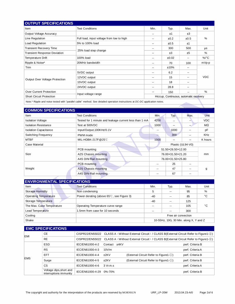
OUTPUT SPECIFICATIONS Item Test Conditions Min. Typ. Max. Unit
Output Voltage Accuracy -- ±1 ±3 Line Regulation Full load, input voltage from low to high -- ±0.2 ±0.5 Load Regulation 5% to 100% load -- ±0.5 ±1
%
Transient Recovery Time -- 300 500 µs
Transient Response Deviation 25% load step change
-- ±3 ±5 %
Temperature Drift 100% load -- ±0.02 -- %/°C
Ripple & Noise* 20MHz bandwidth -- 70 100 mVp-p Trim -- ±10% --
5VDC output -- 6.2 --
12VDC output -- 15 --
15VDC output -- 18 -- Output Over Voltage Protection
24VDC output -- 28.8 --
VDC
Over Current Protection -- 150 -- % Short Circuit Protection
Input voltage range Hiccup, Continuous, automatic recovery
Note:* Ripple and noise tested with “parallel cable” method. See detailed operation instructions at DC-DC application notes.
COMMON SPECIFICATIONS Item Test Conditions Min. Typ. Max. Unit
Isolation Voltage Tested for 1 minute and leakage current less than 1 mA 4200 -- -- VDC
Isolation Resistance Test at 500VDC 1000 -- -- MΩ
Isolation Capacitance Input/Output,100KHz/0.1V -- 1000 -- pF
Switching Frequency PWM mode -- 300 -- KHz
MTBF MIL-HDBK-217F@25℃ 1000 -- -- K hours
Case Material Plastic (UL94-V0)
PCB mounting 51.50×26.50×12.00
A2S Chassis mounting 76.00×31.50×21.20 Size
A4S DIN-Rail mounting 76.00×31.50×25.80
mm
PCB mounting -- 25 --
A2S Chassis mounting -- 47 -- Weight
A4S DIN-Rail mounting -- 67 --
g
ENVIRONMENTAL SPECIFICATIONS Item Test Conditions Min. Typ. Max. Unit
Storage Humidity Non condensing 5 -- 95 %
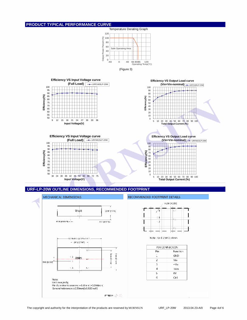
Operating Temperature Power derating (above 65℃, see Figure 3) -40 -- 85 °C
Storage Temperature -40 -- 125 The Max. Case Temperature Operating Temperature curve range -- -- 105
Lead Temperature 1.5mm from case for 10 seconds -- -- 300
°C
Cooling Free air convection Shake 10-55Hz, 10G, 30 Min. along X, Y and Z EMC SPECIFICATIONS
CE CISPR22/EN55022 CLASS A(Without External Circuit)/ CLASS B(External Circuit Refer to Figure1-②) EMI
RE CISPR22/EN55022 CLASS A(Without External Circuit)/ CLASS B(External Circuit Refer to Figure1-②)
ESD IEC/EN61000-4-2 Contact ±4KV perf. Criteria B
RS IEC/EN61000-4-3 10V/m perf. Criteria A
EFT IEC/EN61000-4-4 ±2KV (External Circuit Refer to Figure1-①) perf. Criteria B
Surge IEC/EN61000-4-5 ±2KV (External Circuit Refer to Figure1-①) perf. Criteria B
CS IEC/EN61000-4-6 3 Vr.m.s perf. Criteria A
EMS
Voltage dips,short and interruptions immunity IEC/EN61000-4-29 0%-70% perf. Criteria B
The copyright and authority for the interpretation of the products are reserved by MORNSUN URF_LP-20W 2013.04.23-A/0 Page 3of 6
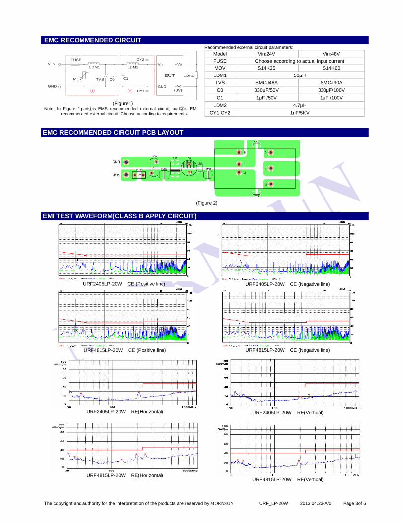
EMC RECOMMENDED CIRCUIT
LDM2
②
C0TVS
LDM1
MOV
FUSE
①
C1
V in
GND
+
Vin
GND
+Vo
-Vo(0V)
EUT LOAD
CY2
CY1
(Figure1)
Note: In Figure 1,part①is EMS recommended external circuit, part②is EMI recommended external circuit. Choose according to requirements.
Recommended external circuit parameters: Model Vin:24V Vin:48V FUSE Choose according to actual input current MOV S14K35 S14K60 LDM1 56μH TVS SMCJ48A SMCJ90A C0 330μF/50V 330μF/100V C1 1μF /50V 1μF /100V
LDM2 4.7μH CY1,CY2 1nF/5KV
EMC RECOMMENDED CIRCUIT PCB LAYOUT
(Figure 2)
EMI TEST WAVEFORM(CLASS B APPLY CIRCUIT)
URF2405LP-20W CE (Positive line)
URF2405LP-20W CE (Negative line)
URF4815LP-20W CE (Positive line)
URF4815LP-20W CE (Negative line)
URF2405LP-20W RE(Horizontal)
URF2405LP-20W RE(Vertical)
URF4815LP-20W RE(Horizontal)
URF4815LP-20W RE(Vertical)
The copyright and authority for the interpretation of the products are reserved by MORNSUN URF_LP-20W 2013.04.23-A/0 Page 4of 6
PRODUCT TYPICAL PERFORMANCE CURVE Temperature Derating Graph
0
20
40
60
80
100
120
-40 0 40 80 12065 85Operating Temp(°C)
Out
put P
ower
Per
cent
(%)
Safe Operating Area
(Figure 3)
Efficiency VS Input Voltage curve(Full Load)
50
55
60
65
70
75
80
85
90
95
100
9 12 15 18 21 24 27 30 33 36
Input Voltage(V)
Effic
ienc
y(%
)
URF2405LP-20W
Efficiency VS Input Voltage curve(Full Load)
50
55
60
65
70
75
80
85
90
95
100
18 24 30 36 42 48 54 60 66 72 75
Input Voltage(V)
Effic
ienc
y(%
)
URF4815LP-20W
Efficiency VS Output Load curve(Vin=Vin-nominal)
0
10
20
30
40
50
60
70
80
90
100
5 10 20 30 40 50 60 70 80 90 100Total Output Current (%)
Effi
cien
cy(%
)
URF2405LP-20W
Efficiency VS Output Load curve(Vin=Vin-nominal)
0
10
20
30
40
50
60
70
80
90
100
5 10 20 30 40 50 60 70 80 90 100Total Output Current (%)
Effic
ienc
y(%
)
URF4815LP-20W
URF-LP-20W OUTLINE DIMENSIONS, RECOMMENDED FOOTPRINT
The copyright and authority for the interpretation of the products are reserved by MORNSUN URF_LP-20W 2013.04.23-A/0 Page 5of 6
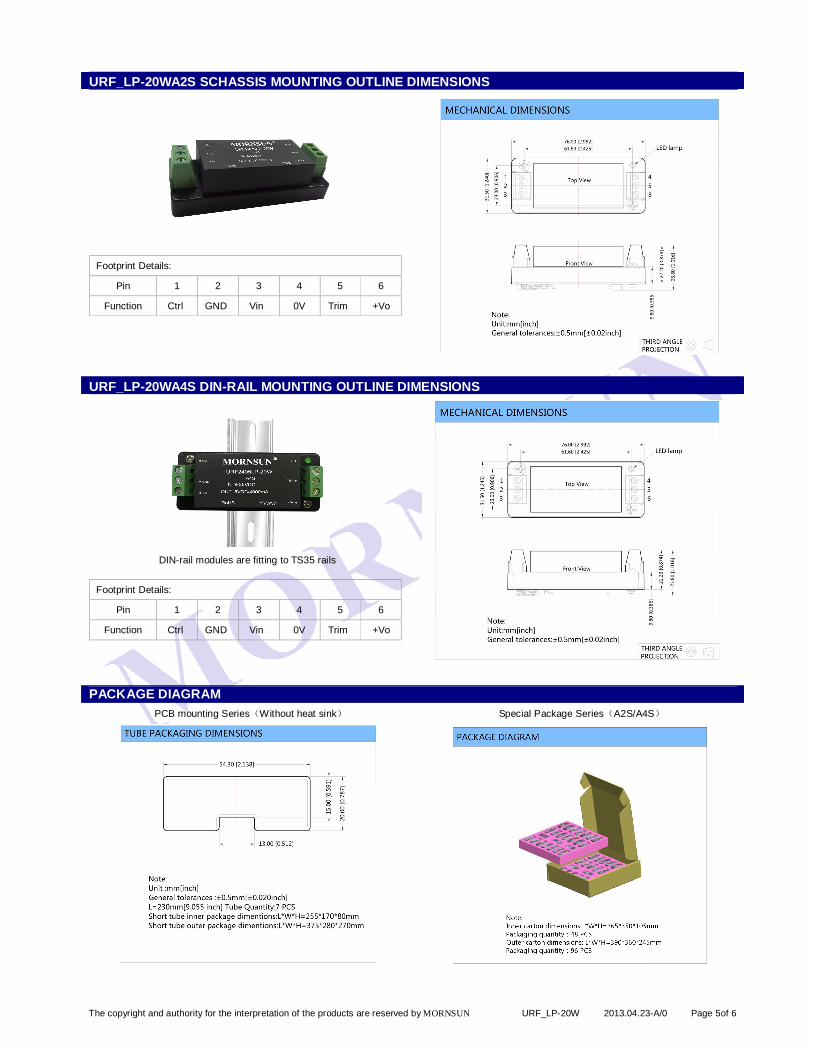
URF_LP-20WA2S SCHASSIS MOUNTING OUTLINE DIMENSIONS
Footprint Details:
Pin 1 2 3 4 5 6
Function Ctrl GND Vin 0V Trim +Vo
URF_LP-20WA4S DIN-RAIL MOUNTING OUTLINE DIMENSIONS
DIN-rail modules are fitting to TS35 rails
Footprint Details:
Pin 1 2 3 4 5 6
Function Ctrl GND Vin 0V Trim +Vo
PACKAGE DIAGRAM PCB mounting Series(Without heat sink) Special Package Series(A2S/A4S)
The copyright and authority for the interpretation of the products are reserved by MORNSUN URF_LP-20W 2013.04.23-A/0 Page 6of 6
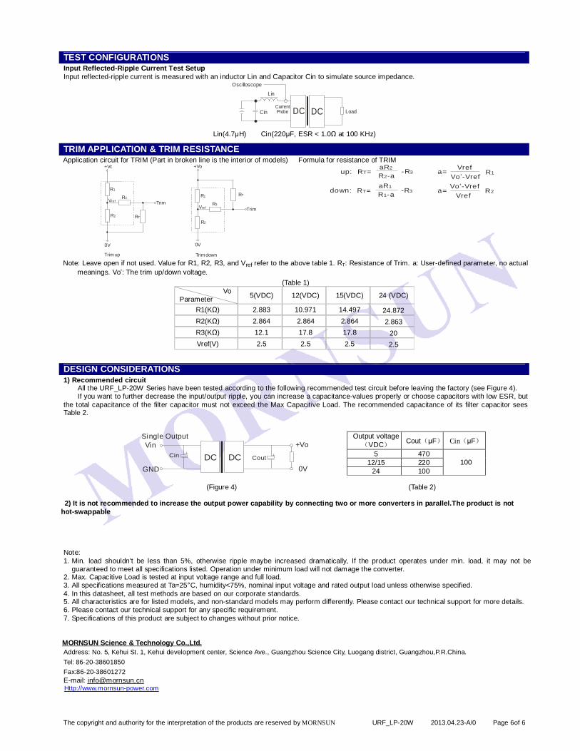
TEST CONFIGURATIONS Input Reflected-Ripple Current Test Setup Input reflected-ripple current is measured with an inductor Lin and Capacitor Cin to simulate source impedance.
DCCin
Lin
DC Load
Oscilloscope
Current Probe
Lin(4.7µH) Cin(220µF, ESR < 1.0Ω at 100 KHz)
TRIM APPLICATION & TRIM RESISTANCE Application circuit for TRIM (Part in broken line is the interior of models)
0V
R2
R1
R3Vref
RT
Trim
+Vo
0V
R2
R1
R3Vref
RT
Trim
+Vo
Trim up Trim down
Formula for resistance of TRIM up: a=
VrefVo’-Vref
R1R =TaR2
R -a2-R3
down: a=Vref
Vo’-VrefR2R =T
aR1
R -a1-R3
Note: Leave open if not used. Value for R1, R2, R3, and Vref refer to the above table 1. RT: Resistance of Trim. a: User-defined parameter, no actual meanings. Vo’: The trim up/down voltage.
(Table 1) Vo
Parameter 5(VDC) 12(VDC) 15(VDC) 24 (VDC)
R1(KΩ) 2.883 10.971 14.497 24.872 R2(KΩ) 2.864 2.864 2.864 2.863 R3(KΩ) 12.1 17.8 17.8 20 Vref(V) 2.5 2.5 2.5 2.5
DESIGN CONSIDERATIONS 1) Recommended circuit
All the URF_LP-20W Series have been tested according to the following recommended test circuit before leaving the factory (see Figure 4). If you want to further decrease the input/output ripple, you can increase a capacitance-values properly or choose capacitors with low ESR, but
the total capacitance of the filter capacitor must not exceed the Max Capacitive Load. The recommended capacitance of its filter capacitor sees Table 2.
DC DC
Vin
GND
+Vo
0V
Cin Cout
Single Output
(Figure 4) (Table 2)
2) It is not recommended to increase the output power capability by connecting two or more converters in parallel.The product is not hot-swappable
Output voltage(VDC) Cout(μF) Cin(μF)
5 470 12/15 220
24 100 100
Note: 1. Min. load shouldn't be less than 5%, otherwise ripple maybe increased dramatically, If the product operates under min. load, it may not be
guaranteed to meet all specifications listed. Operation under minimum load will not damage the converter. 2. Max. Capacitive Load is tested at input voltage range and full load. 3. All specifications measured at Ta=25°C, humidity<75%, nominal input voltage and rated output load unless otherwise specified. 4. In this datasheet, all test methods are based on our corporate standards. 5. All characteristics are for listed models, and non-standard models may perform differently. Please contact our technical support for more details. 6. Please contact our technical support for any specific requirement. 7. Specifications of this product are subject to changes without prior notice. MORNSUN Science & Technology Co.,Ltd. Address: No. 5, Kehui St. 1, Kehui development center, Science Ave., Guangzhou Science City, Luogang district, Guangzhou,P.R.China. Tel: 86-20-38601850 Fax:86-20-38601272 E-mail: [email protected] Http://www.mornsun-power.com


![20W LED Tube[1].Compressed](https://img.pdfslide.us/doc/110x75/577cbfcd1a28aba7118e293b/20w-led-tube1compressed.jpg)