Embed Size (px)
Citation preview
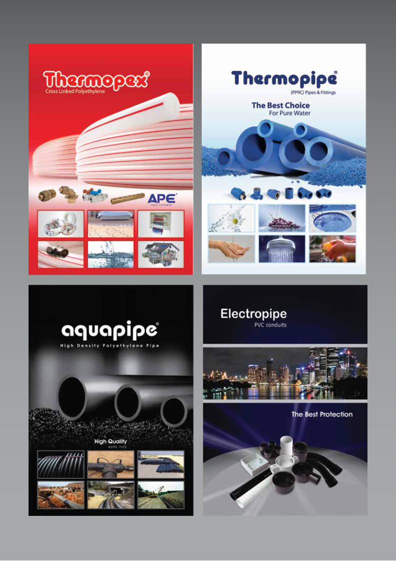
Advanced Piping Systems
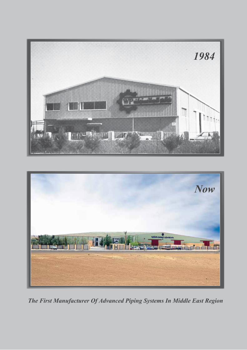
The First Manufacturer Of Advanced Piping Systems In Middle East Region
Now
1984
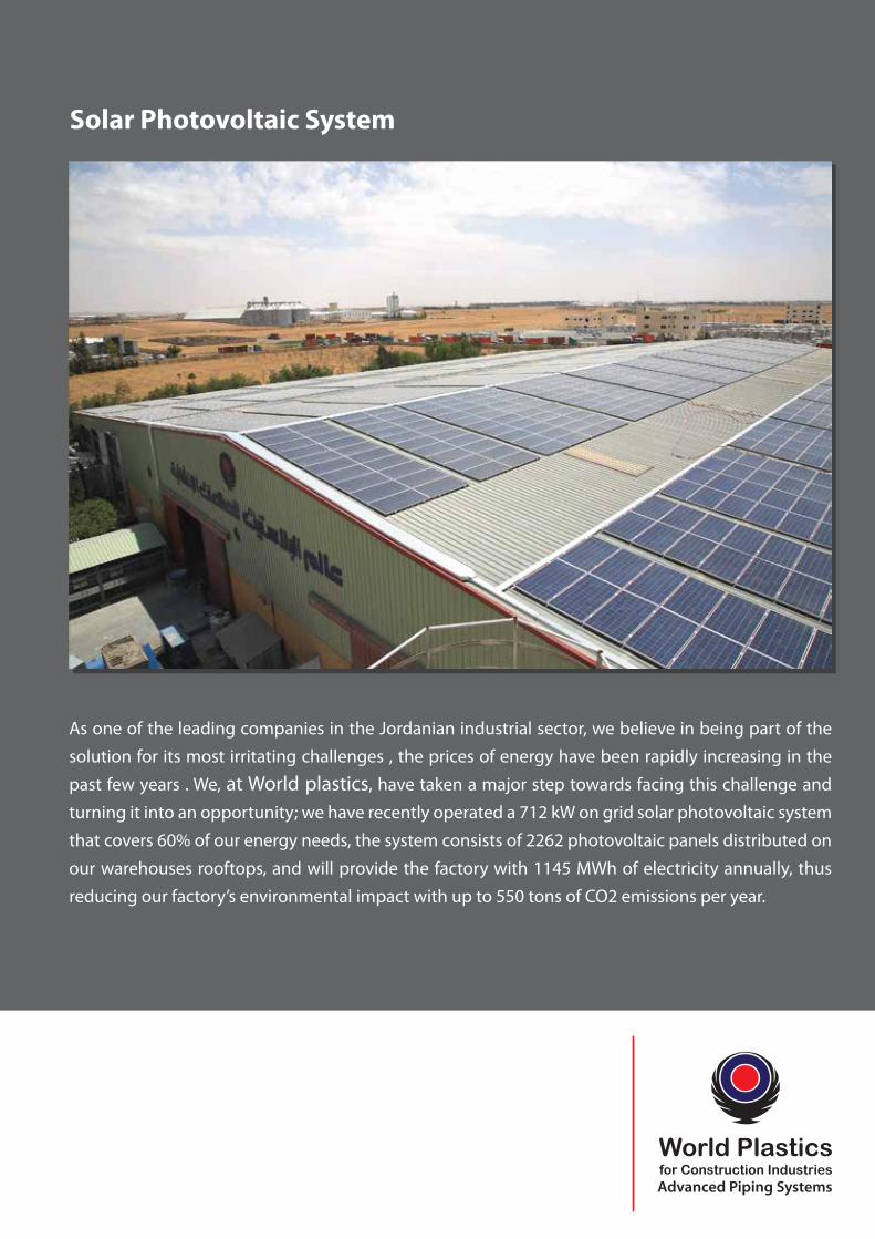
As one of the leading companies in the Jordanian industrial sector, we believe in being part of the
solution for its most irritating challenges , the prices of energy have been rapidly increasing in the
past few years . We, at World plastics, have taken a major step towards facing this challenge and
turning it into an opportunity; we have recently operated a 712 kW on grid solar photovoltaic system
that covers 60% of our energy needs, the system consists of 2262 photovoltaic panels distributed on
our warehouses rooftops, and will provide the factory with 1145 MWh of electricity annually, thus
reducing our factory’s environmental impact with up to 550 tons of CO2 emissions per year.
Solar Photovoltaic System
1
Introduction
World Plastics is a leading company in the development and manufacture of
advanced plastic piping systems since 1984 . Our uniquely extensive range
of large and small bore piping systems are capable of handling a wide variety
of materials in industrial and domestic applications including water , �uid,
waste water , gas and chemicals.
World Plastics , also produces piping systems for drainage and sewage
networks installations . Pipes are made from high quality raw materials and
are manufactured on some of the most advanced machinery in the world
to the most exacting standards.
Our commitment to quality also extends to customer service . You will �nd us
more than willing to help with the design of installations and can advise on
the development of piping systems to meet particular needs.
So , and because of tremendous growth in the industrial, commercial, and
housing sectors in all types of public amenities in Jordan , pipelines are
needed to convey water and sewage, and to protect telecommunication and
electrical cables. To ful�ll this need , World Plastics Company was formed with
the aim of producing , in Jordan, a full range of un-plasticized polyvinyl
chloride ( UPVC ) pipes and �ttings according to international recognized
standards and Jordanian Standards .
2
Production of PVC-U pipes
PVC products are shaped through a thermal and pressure process of PVC
resin powder. Two main processes in production are extrusion for continual
products such as pipe, and molding for separate products such as �ttings.
The modern process of PVC-U needs the use of technical-industrial ways to
accurate control of processing variables. The used polymeric material is a free
�ow powder which needs adding of various stabilizers and lubricants. For this
reason formulation and then mixing are two vital subjects for this process.
The polymer and additives (1) are weighed carefully (2) and sent to mixing
unit (3). High speed mixers mix the raw materials to get a unique dry blend. In
this step a temperature of 120˚ is reached in mixer by friction and shear. After
getting the suitable temperature the mixture is transferred to a cooling tank
automatically and the temperature is reduced to about 50˚ rapidly.
Extruder (4) is the heart of PVC-U pipe process, which has a barrel containing
heat controllable elements in which turns precise screw/screws. The modern
extruders are very complex machines which are designed precisely to control
pressure and shear of the material during all parts of the process.
Adva
nced
Pip
ing
Syst
ems
3
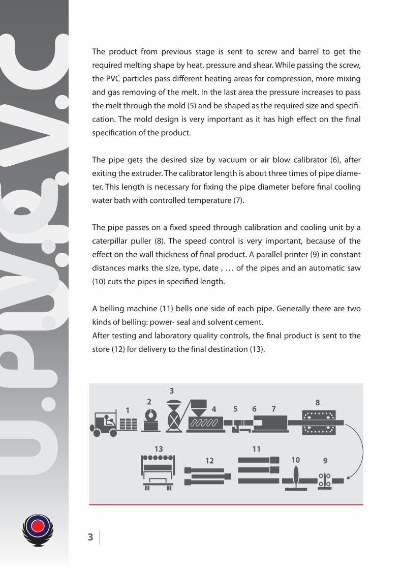
The product from previous stage is sent to screw and barrel to get the
required melting shape by heat, pressure and shear. While passing the screw,
the PVC particles pass di�erent heating areas for compression, more mixing
and gas removing of the melt. In the last area the pressure increases to pass
the melt through the mold (5) and be shaped as the required size and speci�-
cation. The mold design is very important as it has high e�ect on the �nal
speci�cation of the product.
The pipe gets the desired size by vacuum or air blow calibrator (6), after
exiting the extruder. The calibrator length is about three times of pipe diame-
ter. This length is necessary for �xing the pipe diameter before �nal cooling
water bath with controlled temperature (7).
The pipe passes on a �xed speed through calibration and cooling unit by a
caterpillar puller (8). The speed control is very important, because of the
e�ect on the wall thickness of �nal product. A parallel printer (9) in constant
distances marks the size, type, date , … of the pipes and an automatic saw
(10) cuts the pipes in speci�ed length.
A belling machine (11) bells one side of each pipe. Generally there are two
kinds of belling: power- seal and solvent cement.
After testing and laboratory quality controls, the �nal product is sent to the
store (12) for delivery to the �nal destination (13).
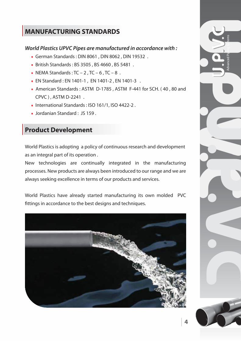
Product Development
World Plastics is adopting a policy of continuous research and development
as an integral part of its operation .
New technologies are continually integrated in the manufacturing
processes. New products are always been introduced to our range and we are
always seeking excellence in terms of our products and services.
World Plastics have already started manufacturing its own molded PVC
�ttings in accordance to the best designs and techniques.
4
MANUFACTURING STANDARDS
World Plastics UPVC Pipes are manufactured in accordance with :• German Standards : DIN 8061 , DIN 8062 , DIN 19532 .
• British Standards : BS 3505 , BS 4660 , BS 5481 .
• NEMA Standards : TC – 2 , TC – 6 , TC – 8 .
• EN Standard : EN 1401-1 , EN 1401-2 , EN 1401-3 .
• American Standards : ASTM D-1785 , ASTM F-441 for SCH. ( 40 , 80 and
CPVC ) , ASTM D-2241 .
• International Standards : ISO 161/1, ISO 4422-2 .
• Jordanian Standard : JS 159 .
Adva
nced
Pip
ing
Syst
ems
5
Fields of UPVC Pipes and Fittings Applications
World Plastics UPVC pipes and �ttings are widely used in :
• Water Supplies Non-toxic World Plastics UPVC pipes will not a�ect the taste , color , or
smell of drinking water .They will never corrode and are therefore
extremely sanitary. Deposits and scales will not buildup inside as in the
case for convention al steel pipes .Their strength is greater than that of
asbestos pipes.
• Irrigation Systems World Plastics UPVC pipes are ideal for agricultural irrigation and sprinkler
systems . Non-corrosive UPVC pipes are perfect for carrying water which
contains chemical fertilizers and insect inhibiters .In thick wall and large
diameter UPVC pipes liquids can be transported under high pressure
,which is convenient for the management of large farms .
• Industry Resistant to most chemicals , UPVC pipes have an important role to play in
industrial plants . Light , noncorrosive , and easy to assemble , they allow
more complex piping work than with steel or cast – iron pipes .
• Soil , Waste & Drainage Sewer System Waste lines for corrosive gases , ventilation for o�ce buildings and facto-
ries ; drainage systems for private homes and elevated high ways these are
a few of the many possibilities for UPVC pipes .
• Mining UPVC pipes particularly well suited for draining corrosive liquids found in
mines. They make an ideal vent line for pits because they are easily
installed in hard to reach places.
• Electrical & Telecommunications Lines ( as Conduits for Cables and Fiber Optics )
Since UPVC pipes are themselves for man integral insulator , there is an
ever-increasing demand for them as electrical conduit . To facilitate work, a
full line of �ttings is available and fabricated from the same material as the
pipes .
6
Range of Production
Water Supplies
Pipes are manufactured according to Jordanian , DIN Standards from16 mm
up to 250 mm outside diameter in various pressure classes , details of which
are shown later in our catalogue .
UPVC pipes are available with spigot and solvent weld socket joints for Diam-
eters less than 63 mm , Sizes of outside diameter and larger are available with
either mechanical rubber ring joints or solvent weld socket joints .
Pipes manufactured in accordance with ASTM , BS Standards or EN Standards
are ranging from ( ½ inch ) up to ( 8 inches ) in various pressure ratings . Pipes
are produced in 6 meters standard length ( other lengths are available upon
request ) .
Standard colors are ; Grey, White, Yellow , and orange
( other colors are available upon request ).
Features of UPVC Pipes and Fittings
• Ease of handling , installation and maintenance .
• Chemical , corrosion and abrasion resistance .
• Low thermal expansion .
• Low bacteria build up .
• Fire Proof .
• Low friction loss .
• Resistance to Galvanic or Electrolytic attack .
• Noise reduction ( compared to metallic pipes ) .
• Cost E�ectiveness .
• Thrust Resistance .
Adva
nced
Pip
ing
Syst
ems
7
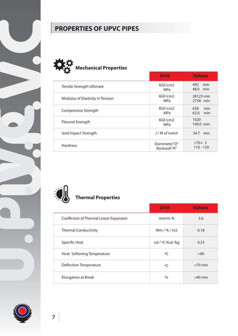
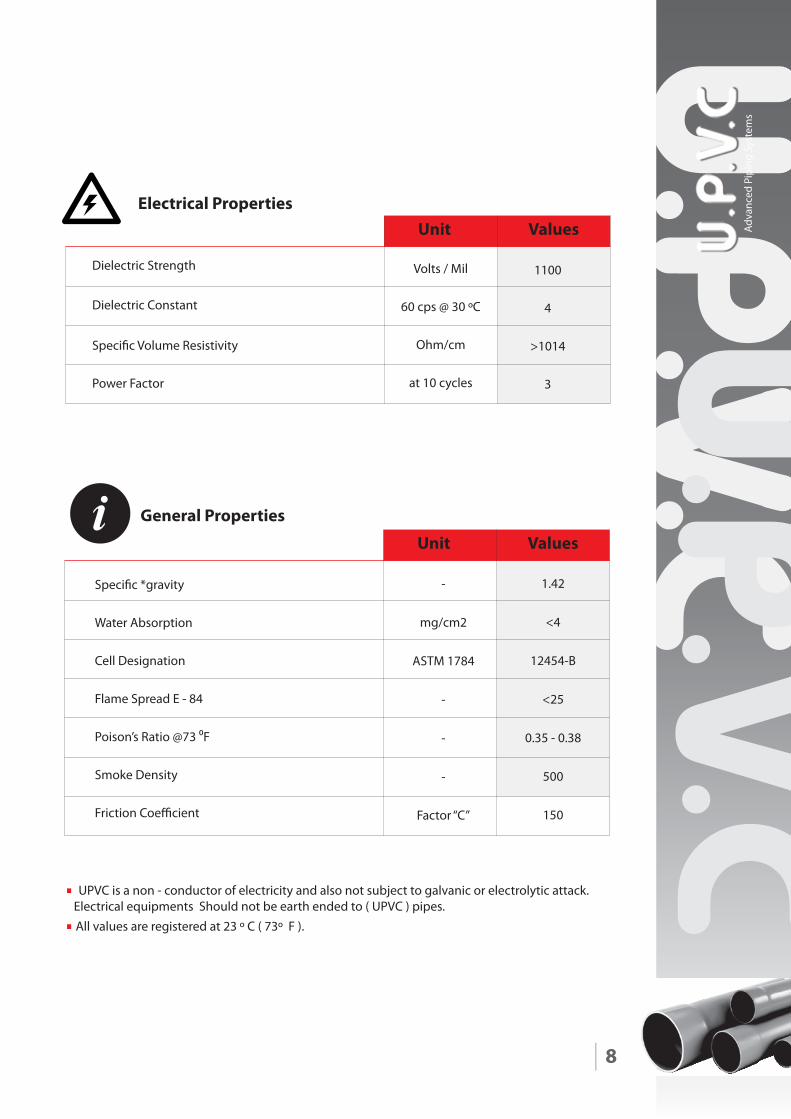
PROPERTIES OF UPVC PIPES
Unit Values
KGF/cm2 MPa
KGF/cm2 MPa
KGF/cm2 MPa
KGF/cm2 MPa
Durometer”D”Rockwell “R”
J / M of notch
492 min48.0 min
28123 min2758 min
638 min62.0 min
>70+- 3110 - 120
1020 100.0 min
34.7 min
Thermal Properties
Mechanical Properties
Tensile Strength Ultimate
Modulus of Elasticity in Tension
Compressive Strength
Flexural Strength
Izod Impact Strength
Hardness
Unit Values
mm/m ºk
Wm / ºk / m2
cal / ºC Kcal /kg
ºC
%
ºC
5.6
0.18
0.23
>40 min
>80
>70 min
Coe�cient of Thermal Linear Expansion
Thermal Conductivity
Speci�c Heat
Vicat Softening Temperature
De�ection Temperature
Elongation at Break
8
Speci�c *gravity
Water Absorption
Cell Designation
Flame Spread E - 84
Poison’s Ratio @73 0F
Smoke Density
Friction Coe�cient
• UPVC is a non - conductor of electricity and also not subject to galvanic or electrolytic attack. Electrical equipments Should not be earth ended to ( UPVC ) pipes.• All values are registered at 23 º C ( 73º F ).
General Properties
Unit ValuesElectrical Properties
Dielectric Strength
Dielectric Constant
Speci�c Volume Resistivity
Power Factor
Unit Values
1100
4
>1014
3
Volts / Mil
60 cps @ 30 ºC
Ohm/cm
at 10 cycles
-
mg/cm2
ASTM 1784
-
-
-
Factor “C”
1.42
<4
12454-B
<25
0.35 - 0.38
500
150
Adva
nced
Pip
ing
Syst
ems
9
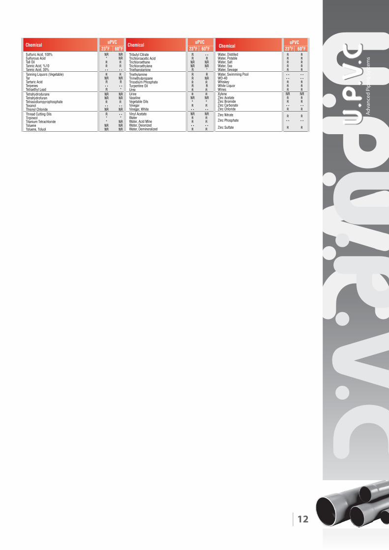
CHEMICAL RESISTANCE OF UPVC PIPES
UPVC & CPVC pipes and �ttings have excellent chemical resistance to most
mineral acids, bases, salts, and aliphatic hydrocarbons. When they are used
within their allowable pressure and temperature ranges, they will provide a
good alternative to metallic piping which corrodes when exposed to the
same aggressive chemical solutions. The information contained in the follow-
ing chemical resistance tables are based on data supplied to us by our raw
material manufacturers and some actual �eld experience gathered from
various sources. You must take into consideration the speci�c use conditions
that will apply to your project. There will be variables that will a�ect the chemi-
cal resistance such as: temperature, pressure, chemical concentration, and
external stresses that may exist in the design and construction of the system.
Because of the wide variety and numerous use conditions that are found in
the process chemical industry, the �nal decision to use thermoplastic piping
should be based on in-service testing and evaluation by the responsible engi-
neer and end-user.
INTERPRETATION OF THE DATA :
It is important to understand that an “R” rating does not necessarily imply that
pipe, �ttings, and joints can be used at their water pressure rating and be
expected to have the same longevity when used with a particular chemical
other than water. Generally, the chemical resistance of UPVC and CPVC will
decrease with an increase in temperature and concentrations. This is also true
for all other components in the system that will come in contact with the �ow.
Solvent cements, valves, instrumentation, o-rings, gaskets, and other such
components should be evaluated and approved by their respective manufac-
turers.
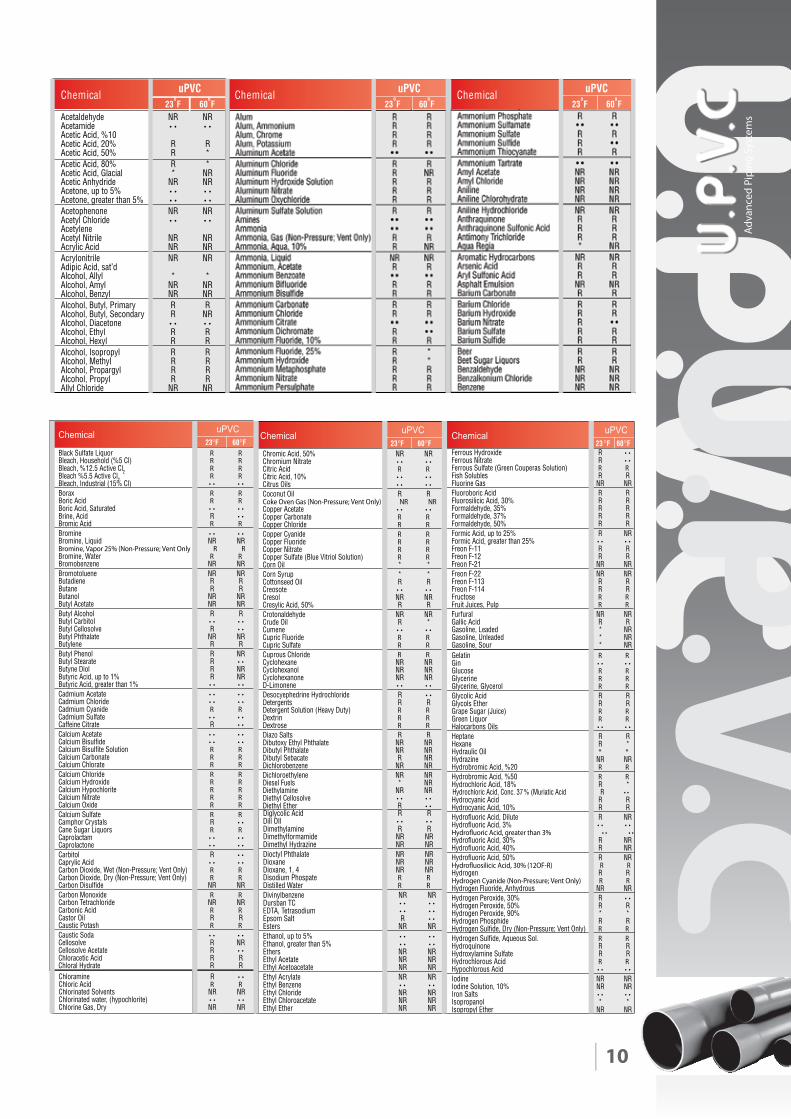
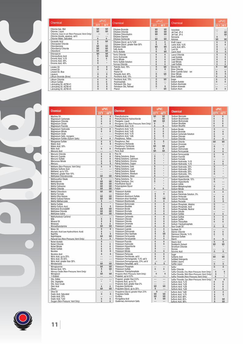
R = Recommended For Use
NR = Not Recommended
…… = No Data Available, Check With Factory.
RNRNedyhedlatecA edimatecA
Acetic Acid, %10RR%02 ,dicA citecA*R%05 ,dicA citecA*R%08 ,dicA citecARN*laicalG ,dicA citecARNRNedirdyhnA citecA %5 ot pu ,enotecA %5 naht retaerg ,enotecARNRNenonehpotecA edirolhC lytecA
AcetyleneRNRNelirtiN lytecARNRNdicA cilyrcARNRNelirtinolyrcA
Adipic Acid, sat’d**lyllA ,lohoclARNRNlymA ,lohoclARNRNlyzneB ,lohoclA
RRyramirP ,lytuB ,lohoclARNRyradnoceS ,lytuB ,lohoclA enotecaiD ,lohoclARRlyhtE ,lohoclARRlyxeH ,lohoclARRlyporposI ,lohoclARRlyhteM ,lohoclARRlygraporP ,lohoclARRlyporP ,lohoclARNRNedirolhC lyllA
lacimehClacimehClacimehC uPVC23
oF 60
oF
uPVC23
oF 60
oF
uPVC23
oF 60
oF
Adva
nced
Pip
ing
Syst
ems
10
11
Adva
nced
Pip
ing
Syst
ems
12
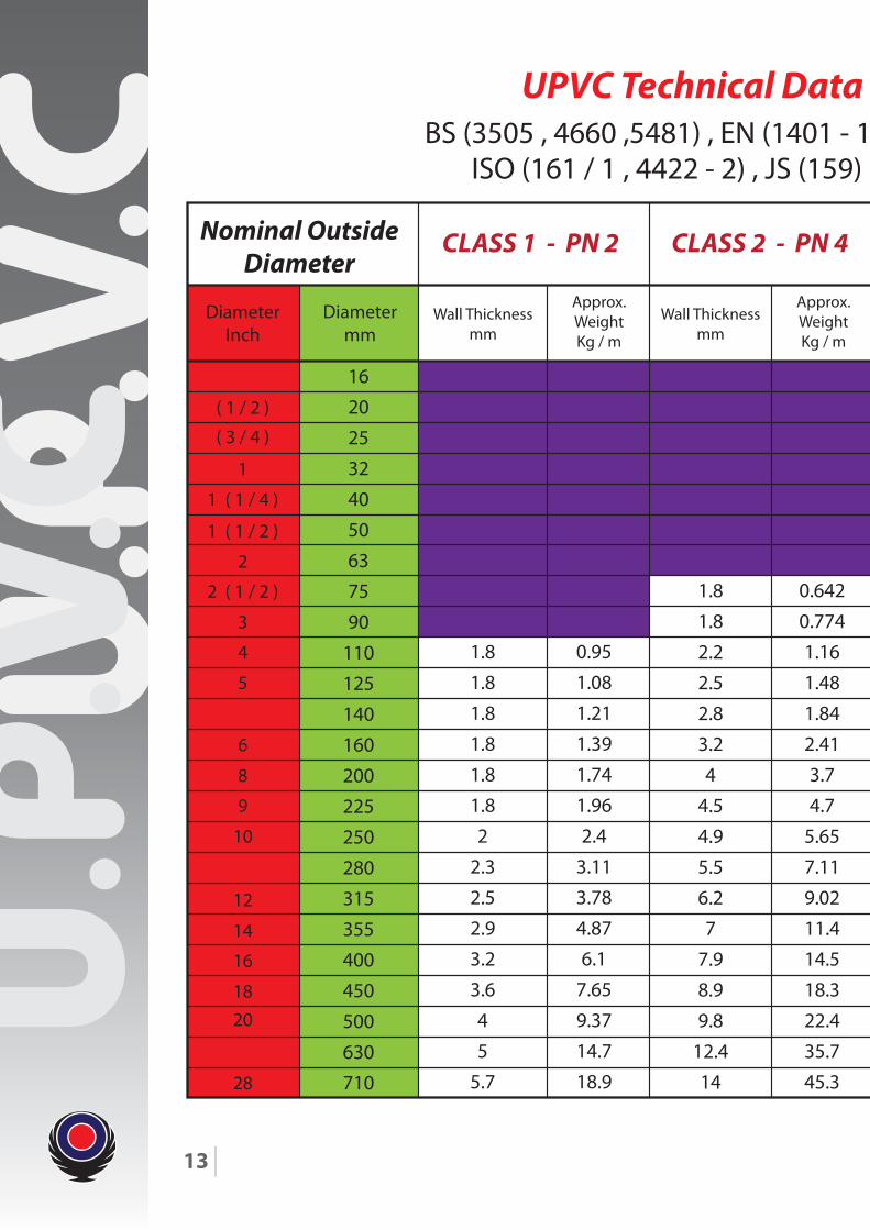
ISO (161 / 1 , 4422 - 2) , JS (159) , ASTM (F - 441 , D - 2241)BS (3505 , 4660 ,5481) , EN (1401 - 1 / 2 / 3) , DIN (8061 , 8062 , 19532),
UPVC Technical Data Table - According to:
DiameterInch
( 1 / 2 )
16
20
25
32
40
50
63
75
90
110
125
140
160
200
225
250
280
315
355
400
450
500
630
710
1.8
1.8
1.8
1.8
1.8
1.8
2
2.3
2.5
2.9
3.2
3.6
4
5
5.7
0.95
1.08
1.21
1.39
1.74
1.96
2.4
3.11
3.78
4.87
6.1
7.65
9.37
14.7
18.9
1.8
1.8
2.2
2.5
2.8
3.2
4
4.5
4.9
5.5
6.2
7
7.9
8.9
9.8
12.4
14
0.642
0.774
1.16
1.48
1.84
2.41
3.7
4.7
5.65
7.11
9.02
11.4
14.5
18.3
22.4
35.7
45.3
( 3 / 4 )
1 ( 1 / 4 )
1 ( 1 / 2 )
2 ( 1 / 2 )
3
4
5
6
8
9
10
12
14
16
1820
28
2
1
Diametermm
Wall Thicknessmm
Wall Thicknessmm
Approx.WeightKg / m
Approx.WeightKg / m
Nominal OutsideDiameter
CLASS 1 - PN 2 CLASS 2 - PN 4
13
ISO (161 / 1 , 4422 - 2) , JS (159) , ASTM (F - 441 , D - 2241)BS (3505 , 4660 ,5481) , EN (1401 - 1 / 2 / 3) , DIN (8061 , 8062 , 19532),
UPVC Technical Data Table - According to:
1.8
1.8
1.9
2.2
2.7
3.2
3.7
4.1
4.7
5.9
6.6
7.3
8.2
9.2
10.4
11.7
13.2
14.6
18.4
20.7
0.334
0.422
0.562
0.782
1.13
1.64
2.13
2.65
3.44
5.37
6.76
8.31
10.4
13.1
16.7
21.1
26.8
32.9
52.2
66.1
1.5
1.8
1.9
2.4
3
3.6
4.3
5.3
6
6.7
7.7
9.6
10.8
11.9
13.4
15
16.9
19.1
21.5
23.9
30
0.174
0.264
0.35
0.552
0.854
1.22
1.75
2.61
3.34
4.1
5.47
8.51
10.8
13.2
16.6
20.9
26.5
33.7
42.7
52.6
83.2
1.2
1.5
1.9
2.4
3
3.7
4.7
5.6
6.7
8.2
9.3
10.4
11.9
14.9
16.7
18.6
20.8
23.4
26.3
29.7
0.09
0.137
0.212
0.342
0.525
0.809
1.289
1.82
2.61
3.9
5.01
6.27
8.17
12.8
16.1
19.9
24.9
31.5
39.9
508
Wall Thicknessmm
Approx.WeightKg / m
Wall Thicknessmm
Approx.WeightKg / m
Wall Thicknessmm
Approx.WeightKg / m
CLASS 4 - PN 10CLASS 3 - PN 6 CLASS 5 - PN 16
14
Adva
nced
Pip
ing
Syst
ems
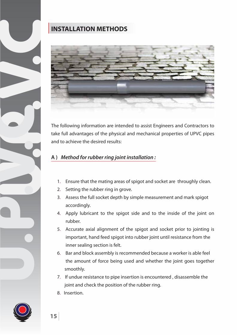
INSTALLATION METHODS
The following information are intended to assist Engineers and Contractors to
take full advantages of the physical and mechanical properties of UPVC pipes
and to achieve the desired results:
A ) Method for rubber ring joint installation :
1. Ensure that the mating areas of spigot and socket are throughly clean.
2. Setting the rubber ring in grove.
3. Assess the full socket depth by simple measurement and mark spigot
accordingly.
4. Apply lubricant to the spigot side and to the inside of the joint on
rubber.
5. Accurate axial alignment of the spigot and socket prior to jointing is
important, hand feed spigot into rubber joint until resistance from the
inner sealing section is felt.
6. Bar and block assembly is recommended because a worker is able feel
the amount of force being used and whether the joint goes together
smoothly.
7. If undue resistance to pipe insertion is encountered , disassemble the
joint and check the position of the rubber ring.
8. Insertion.
15
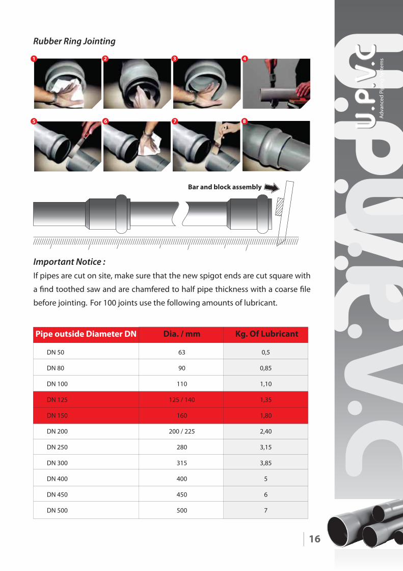
Important Notice :If pipes are cut on site, make sure that the new spigot ends are cut square with
a �nd toothed saw and are chamfered to half pipe thickness with a coarse �le
before jointing. For 100 joints use the following amounts of lubricant.
16
Bar and block assembly
1 2 3 4
5 6 7 8
Rubber Ring Jointing
Pipe outside Diameter DN Dia. / mm Kg. Of Lubricant
DN 50
DN 80
DN 100
DN 125
DN 150
DN 200
DN 250
DN 300
DN 400
DN 450
DN 500
63
90
110
125 / 140
160
200 / 225
280
315
400
450
500
0,5
0,85
1,10
1,35
1,80
2,40
3,15
3,85
5
6
7
Adva
nced
Pip
ing
Syst
ems
B ) Method of solvent welded joint installation :
1. Joint Preparation - Cut Pipe square with the axis, using a �ne - tooth saw
with a miter box or guide. Remove all burrs and break the sharp lead
edges.
2. Cleaning & Priming-Surface to be joined must be cleaned and free of dirt,
Moisture ,Oil ,and other FOREIGN material Applying Weld-On primer.
Mark on spigot the full length of the socket side to make sure that the
spigot will �t exactly the socket length.
4. Application of solvent cement - PVC solvent cement is fast drying and
should be applied as quickly as possible , consistent with good workman
ship , Follow up the manufacturer’s recommendation to both spigot and
socket side with an adequate quantity of cement.
5. Joint Assembly - While both the inside socket surface and the outside
surface of the spigot of the pipe are WET with solvent cement ,forcefully
bottom the spigot in the socket .Turn the pipe or �ttings 1/4 turn during
assembly ( but not after the pipe is bottomed) to distribute the cement
evenly . Hold for a while until handling strength is developed. Assembly
should be completed within 30 seconds after the last application of
solvent cement.
6. After Assembly -Wipe excess cement from the pipe at the end of the
socket . Gaps in the cement bead around the pipe perimeter may indicate
a defective assembly Handle the newly, Assembled joints Carefully after 1
hour.
17
1 2 3
456
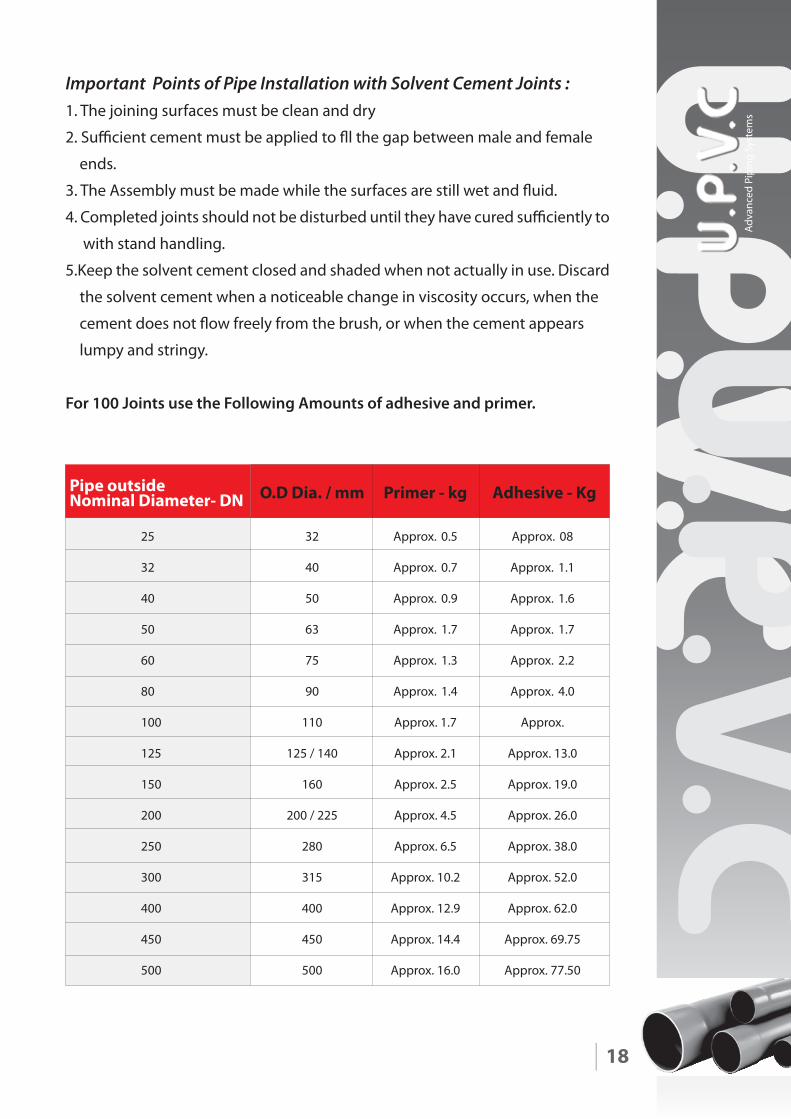
Important Points of Pipe Installation with Solvent Cement Joints :1. The joining surfaces must be clean and dry
2. Su�cient cement must be applied to �l the gap between male and female
ends.
3. The Assembly must be made while the surfaces are still wet and �uid.
4. Completed joints should not be disturbed until they have cured su�ciently to
with stand handling.
5.Keep the solvent cement closed and shaded when not actually in use. Discard
the solvent cement when a noticeable change in viscosity occurs, when the
cement does not �ow freely from the brush, or when the cement appears
lumpy and stringy.
For 100 Joints use the Following Amounts of adhesive and primer.
18
Pipe outsideNominal Diameter- DN O.D Dia. / mm Primer - kg Adhesive - Kg
25
32
40
50
60
80
100
125
150
200
250
300
400
450
500
32
40
50
63
75
90
110
125 / 140
160
200 / 225
280
315
400
450
500
Approx. 0.5
Approx. 0.7
Approx. 0.9
Approx. 1.7
Approx. 1.3
Approx. 1.4
Approx. 1.7
Approx. 2.1
Approx. 2.5
Approx. 4.5
Approx. 6.5
Approx. 10.2
Approx. 12.9
Approx. 14.4
Approx. 16.0
Approx. 08
Approx. 1.1
Approx. 1.6
Approx. 1.7
Approx. 2.2
Approx. 4.0
Approx.
Approx. 13.0
Approx. 19.0
Approx. 26.0
Approx. 38.0
Approx. 52.0
Approx. 62.0
Approx. 69.75
Approx. 77.50
Adva
nced
Pip
ing
Syst
ems
19
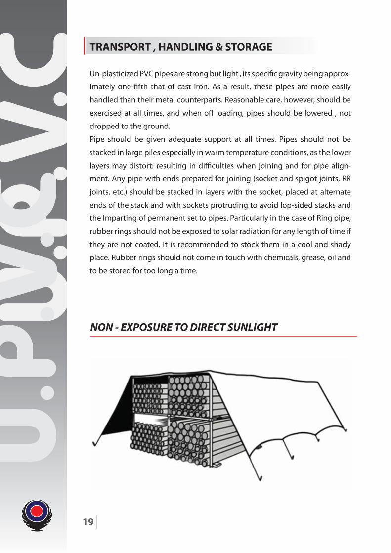
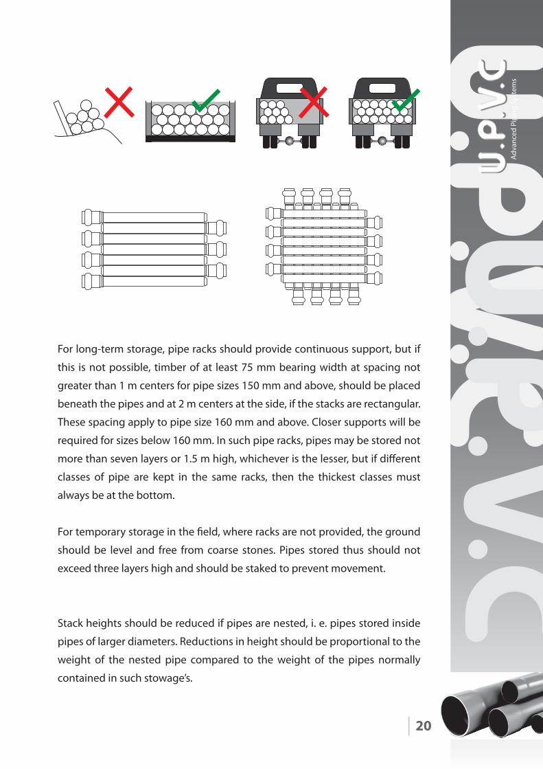
TRANSPORT , HANDLING & STORAGE
Un-plasticized PVC pipes are strong but light , its speci�c gravity being approx-
imately one-�fth that of cast iron. As a result, these pipes are more easily
handled than their metal counterparts. Reasonable care, however, should be
exercised at all times, and when o� loading, pipes should be lowered , not
dropped to the ground.
Pipe should be given adequate support at all times. Pipes should not be
stacked in large piles especially in warm temperature conditions, as the lower
layers may distort: resulting in di�culties when joining and for pipe align-
ment. Any pipe with ends prepared for joining (socket and spigot joints, RR
joints, etc.) should be stacked in layers with the socket, placed at alternate
ends of the stack and with sockets protruding to avoid lop-sided stacks and
the Imparting of permanent set to pipes. Particularly in the case of Ring pipe,
rubber rings should not be exposed to solar radiation for any length of time if
they are not coated. It is recommended to stock them in a cool and shady
place. Rubber rings should not come in touch with chemicals, grease, oil and
to be stored for too long a time.
NON - EXPOSURE TO DIRECT SUNLIGHT
20
For long-term storage, pipe racks should provide continuous support, but if
this is not possible, timber of at least 75 mm bearing width at spacing not
greater than 1 m centers for pipe sizes 150 mm and above, should be placed
beneath the pipes and at 2 m centers at the side, if the stacks are rectangular.
These spacing apply to pipe size 160 mm and above. Closer supports will be
required for sizes below 160 mm. In such pipe racks, pipes may be stored not
more than seven layers or 1.5 m high, whichever is the lesser, but if di�erent
classes of pipe are kept in the same racks, then the thickest classes must
always be at the bottom.
For temporary storage in the �eld, where racks are not provided, the ground
should be level and free from coarse stones. Pipes stored thus should not
exceed three layers high and should be staked to prevent movement.
Stack heights should be reduced if pipes are nested, i. e. pipes stored inside
pipes of larger diameters. Reductions in height should be proportional to the
weight of the nested pipe compared to the weight of the pipes normally
contained in such stowage’s.
Adva
nced
Pip
ing
Syst
ems
21
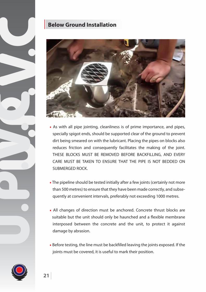
• As with all pipe jointing, cleanliness is of prime importance, and pipes,
specially spigot ends, should be supported clear of the ground to prevent
dirt being smeared on with the lubricant. Placing the pipes on blocks also
reduces friction and consequently facilitates the making of the joint.
THESE BLOCKS MUST BE REMOVED BEFORE BACKFILLING, AND EVERY
CARE MUST BE TAKEN TO ENSURE THAT THE PIPE IS NOT BEDDED ON
SUBMERGED ROCK.
• The pipeline should be tested initially after a few joints (certainly not more
than 500 metres) to ensure that they have been made correctly, and subse-
quently at convenient intervals, preferably not exceeding 1000 metres.
• All changes of direction must be anchored. Concrete thrust blocks are
suitable but the unit should only be haunched and a �exible membrane
interposed between the concrete and the unit, to protect it against
damage by abrasion.
• Before testing, the line must be back�lled leaving the joints exposed. If the
joints must be covered, it is useful to mark their position.
Below Ground Installation
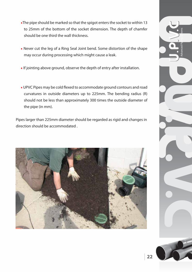
•The pipe should be marked so that the spigot enters the socket to within 13
to 25mm of the bottom of the socket dimension. The depth of chamfer
should be one third the wall thickness.
• Never cut the leg of a Ring Seal Joint bend. Some distortion of the shape
may occur during processing which might cause a leak.
• If jointing above ground, observe the depth of entry after installation.
• UPVC Pipes may be cold �exed to accommodate ground contours and road
curvatures in outside diameters up to 225mm. The bending radius (R)
should not be less than approximately 300 times the outside diameter of
the pipe (in mm).
Pipes larger than 225mm diameter should be regarded as rigid and changes in
direction should be accommodated .
22
Adva
nced
Pip
ing
Syst
ems
Products