Embed Size (px)
Citation preview

UPiC FILE COPY N 3N-1813
Sponsored By Naval Facilities
Technical Note Engineering Command
c RAPID RUNWAY REPAIR (RRR)TECHNIQUES: DTIC
SYSTES ftELECTEA SYSTEMS ANALYSIS AuG16ouu
ABSTRACT An evaluation of nine rapid runway repair (RRR) 60
techniques was performed using the systems analysis approach.This analysis was based on a logical step-by-step procedure ofexamining the smallest details of each RRR system. The primaryobjective was to evaluate the RRR systems against criteria (evalu-ation factors) that were identified to be important in RRR. Thesecriteria included repair time, cost, complexity, etc.
The final results showed that the best RRR systems areasphalt blocks, fiberglass-reinforced plastic (FRP) mats, and FRPfoldable mats. These repair techniques possess the desirable ad-vantages in a RRR system. They are fast, simple, and cost effec-tive, and extensive training is not required.
This study was conducted methodically and each phase wascarefully thought out. It reflects the opinions of the author andleading RRR •xperts. This analysis is not intended to make thedecision of which RRR system to implement; it is merely a tool toclearly state the procedures, factors, and rationale that are used tomake a decision.
NAVAL CIVIL ENGINEERING LABORATORY PORT HUENEME CALIFORNIA 93043-5003
Approved for public release; distribution is unlimited.
90 08 14 153

Form App'ovcdREPORT DOCUMENTATION PAGE O f-.,004o01
Public reporting buirden for this collection of information is estimated to average 1 hcur per response, including the time for reviewing instructions, searching existing data sources.gathering and maintaining the data needed, and completing and reviewing the collection of information. Send comments regarding this burden estimate or any other aspect of thiscollection Information, including suggestions for reducing this burden, to Washington Headquarters Services. Directorate for Information and Reports, 1215 Jefferson Davis Highway.Suite 1204. Arlington. VA 22202-4302, and to the Office of Management and Budget. Paperwork Reduction Project (0704-0188). Washington. DC 20503.
1. AGENCY USE ONLY (Leave blank) 2. REPORT DATE 3. REPORT TYPE AND DATES COVERED
IMay 1990 Final - Jun 87 to Jan 90
4. TITLE AND SUBTITLE 5. FUNDING NUMBERS
Rapid Runway Repair (RRR) Techniques: A Systems PE -Analysis WU-DN387314
6. AUThORIS)
Shujie Chang
7. PERFORMING ORGANIZAllON NAME(S) AND ADDRESSE(S) &. PERFORMING ORGANIZATION
REPORT NUMBER
Naval Civil Engineering Laboratory TN-1813Port Hueneme, CA 93043-5003
9. SPONSORING/MONITORING AGENCY NAME(S) AND ADORESSE(S) 10. SPONSORINGAIONITORING
AGENCY REPORT NUMBER
Naval Facilities Engineering Command200 Stovall StreetAlexandria, VA 22332-2300
11. SUPPLEMENTARY NOTES
12. DIST•IBUTION/AVAILABIUTY STATEMENT 1 2b. DISTRIBUTION CODE
Approved for public release; distribution is unlimited.
13. ABSTRACT (Maximaum 200 wods)
"An evaluation of nine rapid runway repair (RRR) techniques was performed using the sys-tems analysis approach. This analysis was based on a logical step-by-step procedure of examin-ing the smallest details of each RRR system. The primary objective was to evaluate the RRRsystems against criteria (evaluation factors) that were identified to be important in RRR. Thesecriteria included repair time, cost, complexity, etc.
The final results showed that the best RRR systems are asphalt blocks, fiberglass-reinforcedplastic (FRP) mats, and FRP foldable mats. These repair techniques possess the desirable advan-tages in a RRR system. They are fast, simple, and cost effective, and extensive training is notrequired.
This study was conducted methodically and each phase was carefully thought out. It reflectsthe opinions of the author and leading RRR experts. This analysis is not intended to make thedecision of which RRR system to implement; it is merely a tool to clearly state the procedures,factors, and rationale that are used to-jake-addecision. / ,) rcA..
14. SUBJECT TERMS U( 15. NUMBER OF PAGES
Rapid runway repair (RRR ,tairfield damage repair (ADR), FRP, infrared 65heater, base survivability < 1I& PRICE CODE
17. SECURITY CLASSIFICAION IS. SECURITY CLASSIFICATION 19. SECURITY CLASSIFICATION M0. UMITATlON OF ABSTRACTOF REPORT OF THIS PAGE OF ABSTRACT
Unclassified Unclassified Unclassified UL
NSN 7540,01-280-5500 Standard Form 298 (Rer 2-891
Prescribdd by ANSI Sid 239 18298-102
CONTENTSPage
INTRODUCTION .............................................................................................................. 1
BACKGROUND ................................................................................................................ 1
PROBLEM DEFINITION ................................................................................................ I
GOAL AND OBJECTIVES ............................................................................................... 1
ALTERNATIVES .......................................................................................................... I
Fiberglass-Reinforced Plastic (FRP) M ats ............................................................ 2Bolt-Together FRP Panels ..................................................................................... 2Foldable FRP M ats .............................................................................................. 2Precast Concrete Slabs ......................................................................................... 2Precast Asphalt Concrete Block ............................................................................ 2M agnesium Phosphate ......................................................................................... 3Crushed Rock ....................................................................................................... 3Polyurethane Cap .................................................................................................. 3AM -2 Aluminum M atting .................................................................................... 3
CRITERIA ......................................................................................................................... 3
STATES OF NATURE AND ASSOCIATED PROBABILITIES ...................................... 4
UTILITY M EASUREM ENTS ......................................................................................... 5
COM PARISON OF ALTERNATIVES ........................................................................... 5
SENSITIVITY ANALYSIS ............................................................................................. 6
COM M ENTS AND CONCLUSIONS .............................................................................. 6
APPENDIX A - Using Delphi Analysis and Brainstorming as ProblemSolving Techniques for Rapid Runway Repair (RRR) ....................... A-i ?or
Undawoumoed 00
Just Irioatiam....
-_D i stP J butlSAvasebulty coded
v Dist speaw

INTRODUCTION able at a fixed base that can be tailored toward theirequipment and manpower allotment.
This report examines and analyzes nine rapid runway Because there are many factors and philosophies in-repair (RRR) techniques that are currently available. It volved, difficulties may arise in choosing the best RRRuses the systems analysis approach and applies this ap- technique. Often the best alternative will vary, dependingproach to certain decision problems for choosing a RRR on the concerned parties. Therefore, a systematic approachtechnique. Systems analysis is a philosophy, a concept, a must be used that focuses on solving a complex problem byway of looking at a set of problems. It is an analytic tying together the pertinent details in a logical manner.inquiry designed to help decision makers identify a pre-ferred choice among possible alternatives. The emphasis ison the clarification of objectives, on the search for altema- PROBLEM DEFINITIONtives, on explicitness, on recognition of uncertainty, and onthe use of quantitative models. The NCF currently does not have a defined acceptable
The scenario for this analysis is set for a fixed base in RRR technique to repair damage to airfield runway pave-Europe. This analysis is designed to help the Naval Facili- ments caused by enemy munitions. Naval airfields areties Engineering Command (NAVFAC) examine the RRR extremely vulnerable to enemy attack in any conflictsalternatives available and analyze their overall implica- involving the United States. The enemy can inflict severetions for airfield operations in Europe. It leans heavily on damage to airfield runways with sophisticated munitionsthe use of expert opinion and human judgment. The basic designed to crater and spall a runway. To restore airfieldidea is to break a complex problem into component parts, operations, the NCF must be able to perform the associatedwork separately on these parts, and then put the parts tasks to quickly repair a runway.together where the implications for the final decision areclearly specified. It must be stressed that this analysis is foruse as a decision making tool only, it is not the decision GOAL AND OBJECTIVESmaker.
The overall goal of this analysis is to provide a methodfor NAVFAC to analyze and select the best RRR tech-
BACKGROUND niques available to restore an airfield to operational statusfollowing enemy attack. The objectives are to present
In the event of hostilities involving the United States, feasible alternatives to the problem and to provide NAVFACthe U.S. Naval airfields are critical assets for maritime with all the relevant information necessary for decisionpatrol operations, tactical fleet resupply, and combat sup- making through a logical, systematic, and consistent ap-port mission aircraft operations. Damage to airfield pave- proach.ments from sophisticated enemy munitions threatens sus-tained aircraft sorties until the airfield is repaired. There-fore, it is essential that the Naval Construction Force (NCF) ALTERNATIVEShave a RRR capability to restore the airfield's launch andrecovery operations. Nine RRR alternative techniques were researched and
Over the past 15 years, the United States and other considered as suitable. These alternatives were analyzedNorthern Atlantic Treaty Organization (NATO) nations based on previous and current research data gathered fromhave conducted extensive research toward developing en- the United States Air Force, Army, and Navy, and thehanced RRR capabilities (materials, equipment, and tech- Royal Engineers from the United Kingdom. Each altema-niques). Several of these capabilities have been tested tive is examined and evaluated, in relation with one an-successfully and fielded by various services. The NCF is other, based on the defined criteria (evaluation factors). Itcurrently trying to determine the best RRR technique avail- is assuned that the decision maker has all power over men,
I

money, and materials, therefore implementation factors Foldable FRP Matsare not considered. The nine alternatives are summarizedbelow and Table I shows the advantages and disadvan- Foldable FRP mats are made of two plies of 4020 sty,.:tages of each repair system. fiberglass impregnated with polyester resin (see Figures 4
and 5). The mats consist of a number of panels which areFiberglass-Reinforced Plastic (FRP) Mats joined along the edges with fiberglass hinges and impreg-
nated with a flexible polyurethane. The flexible jointsFRP mats are made of two to three plies of 4020 style allow the mat to be folded, thereby allowing the mats to be
fiberglass impregnated with polyester resin (see Figure 1). air transportable. Foldable FRP mats can also be gluedThe traditional mat dimensions are approximately 60 square together or cut to make larger or smaller patches if neces-feet; however, mats of other sizes can also be made. The sary.mats, which are not transportable due to their dimensions, The repair procedures for using foldable FRP mats aremust be fabricated at the site. If the mat size is not large identical to the FRP mat crater repair techniques.enough or too large, two mats can be glued together or onemat can be cut with a circular saw to the desired dimen- Precast Concrete Slabssions.
The general procedures for FRP mat crater repair are: This repair, which was developed by the United StatesAir Force Europe (USAFE), uses precast concrete slabs.
1. Backfill the crater with existing debris to within 18 to The slabs, which are made of Portland cement concrete,24 inches of pavement surface. measure 2 meters by 2 meters by 15 centimeters thick and
have reinforcing strips along the squared top edges (see2. Fill the crater with well-graded crushed rock up to 2 to Figure 6). The general procedures for this repair are to:4 inches above the pavement surface and compact it topavement level with a vibratory roller. 1. Remove all the debris from the crater.
3. Tow FRP mat over repair and bolt to pavement sur- 2. Saw and break away the concrete around the craterface. perimeter to ensure a square or rectangular crater shape.
4, Construct a polymer concrete ramp on the mat's lead- 3. Fill the crater with ballast rock up to 10 inches froming edges to facilitate tailhook operations. the pavement surface and overlay with a 4- to 5-inch-thick
layer of uniform 3/8-inch sized gravel as a leveling course.This repair method assumes that the crater does not
contain standing water, and that the debris backfill is rea- 4. Level the gravel with a screed beam to about 4 inchessonably firm (California Bearing Ratio of 3 to 5). When below the pavement surface.standing water is present inside the crater, the crater shouldbe backfilled with choked-ballast rock to within 4 to 6 5. Place the precast concrete slabs onto the leveling courseinches of the pavement surface. Crushed rock is then filled and compact using a roller.to 2 to 4 inches above the pavement surface and compactedlevel with the pavement surface. Precast Asphalt Concrete Block
Bolt-Together FRP Panels This crater repair technique uses asphalt concrete blocksthat are preformed and precompacted. The asphalt con-
Bolt-together FRP panels are made of three plies of crete block dimensions are 24 inches wide by 24 inches4020 style fiberglass impregnated with polyester resin (see long by 3 to 4 inches thick (see Figures 7 and 8). TheFigures 2 and 3). The basic panel dimensions are 18 feet general procedures for this repair are:long by 6.67 feet wide by 3/8 inch thick and weigh approxi-mately 300 pounds per panel. The panels are air transport- 1. Backfill the crater with existing debris to within 18 toable and can be bolted together at the site to form the 24 inches of the pavement surface.desired dimensions.
The repair procedures for using bolt-together FRP 2. Fill the crater with crushed rock and compact to withinpanels are identical to the FRP mat crater repair tech- 2 to 3 inches of the pavement surface, depending on theniques. block thickness.
2

3. Place asphalt concrete blocks over the crater. 3. Continue filling the crater until percolated concrete iseven with pavement surface; and allow approximately 5
4. Heat asphalt blocks with an infrared heater, level, and minutes for setting until trafficking.compact asphalt to form a flush repair.
AM-2 Aluminum MattingMagnesium Phosphate
AM-2 is an aluminum matting used primarily to sur-This repair method uses a specially formulated non- face runways, taxiways, and parking areas for expedition-
shrinking grout designed to penetrate the voids in the ary airfields. AM-2 is a fabricated aluaninum panel, 1-1/2selected aggregate fill. The grout mixer system is shown in inches thick, that consists of a hollow, extruded, one-pieceFigure 9. The magnesia phosphate cement blended with main section with extruded end connectors welded at eachspecial fillers and accelerators or retarders provides a con- end (Figure 12). Each panel is 12 feet long by 2 feet widetrolled high early-strength pavement under different weather and weighs 144 pounds. The panels are air transportableconditions. The general procedure for this repair is to: (1) and can be assembled at the site to form the desired dimen-fill the crater with ballast fill (2-inch single size) and a sions.leveling layer of graded stone (3/16 to 1-1/4 inch) up to 8 The repair procedures for using AM-2 matting areinches below the pavement surface, and (2) place a grout identical to the FRP mat crater repair techniques.seal geotextile overlain by 8 inches of a deep flood groutedlayer of 5/8- to 7/8-inch crushed rock. After setting, thearea is ready for traffic. CRITERIA
Crushed Rock A number of criteria important in RRR will be used asevaluation factors. These criteria will be evaluated with
The crashed rock repair requires a very high quality, respect to their role in attaining the overall goal. Eachwell-graded crushed rock. The general procedures for criterion will be measured and used for comparison ofcrushed rock repair are: alternatives. These criteria are listed and explained below:
1. Backfill existing debris up to 24 inches from the pave- 1. Equipment Intensiveness: The NCF plans to use thement surface. Advanced Base Functional Component (ABFC) P-36 equip-
ment for most of its crater repair tasks. It is important that2. Fill crushed rock up to the pavement surface and com- the RRR technique chosen does not overtax the availablepact (in several layers). Since no foreign object damage equipment in regard to pieces of equipment, power output(FOD) covers will be used for this repair, it is extremely required, and working time.crucial that the crushed rock be of proper gradation andcompacted to specifications (usually 100 percent of maxi- 2. Dependency: Due to potentially harsh conditions andmum laboratory density as specified by ASTM Modified the possibility of untrained personnel in the working envi-Proctor Test) (see Figure 10). ronment, various tasks within the repair may not be per-
formed to acceptable levels. It is important that the repairPolyurethane Cap technique chosen does not completely depend on proper
performance of all tasks or subtasks to ensure a degree ofThis repair method uses a polyurethane grout designed success.
to penetrate voids in the selected aggregate base. Thepolyurethane is blended with accelerators to control the 3. Need for Dedicated Equipment: Specialized or dedi-setting time to provide a rapid setting high-strength poly- cated equipment may be needed for a given repair tech-mer concrete surface (see Figure 11). The general repair nique. The more dedicated equipment that is needed theprocedures are: more undesirable the repair method becomes.
1. Backfill and level existing debris to 8 to 10 inches 4. Operational (under wide temperature range): Duringbelow pavement surface. the repair, conditiors of extreme cold or heat may exist.
The repair technique chosen should be deployable and2. Fill with uniform size gravel up to pavement surface; operational under the widest temperature range.apply polyurethane polymer concrete and allow it to perco-late down through the gravel to the debris.
3

5. Labor Intensiveness: During the repair, manual labor materials and equipment can be stored in limited space andmay be scarce. The repair technique chosen must not do not require special facilities or containers.overtax the personnel in regard to number and labor inten-siveness. 15. Operational (under wide range of aircraft types): The
airfieid being rcpaired may have to support a wide spec-6. Complexity: Trained personnel may not be available trun of a icraft. The repair method chosen should be ableduring the repair. Therefore, any available personnel such to handle all types of aircraft ranging from cargo to fighteras clerks and cooks may be used to perform RRR. The aircraft.repair technique chosen must be kept as simple as possible.Complexity can result in a greater potential for unforeseen The criteria defined in this section were subjectivelydifficulties and errors. ranked and weighted using the Delphi technique. A ques-
tionnaire was sent to nine RRR experts asking for their7. Peacetime Usage: It is desirable that the crater repair subjective opinions regarding the relative importance oftechnique chosen (equipment and materials) has peacetime each criterion for RRR. This procedure was repeated threeapplications. This would allow the equipment and materi- times, each time (after the first) the experts saw the medianals to be used routinely and productively during peacetime, and 50th percentile answers from their peers. The expertsthereby placing less emphasis on shelf life, cost, and train- were asked to provide explanations if their answers did noting. fall within the 50th percentile range. Table 2 shows the
final criteria rankings (highest to lowest importance) and8. Structural Strength: All repair techniques under analy- weighted values. Appendix A shows the three question-sis have a limited number of aircraft sorties that they can naires that were sent out for this analysis.support before maintenance is required. The more sortiesthat the chosen repair technique can support in betweenmaintenance periods, the more desirable. STATES OF NATURE AND ASSOCIATED
PROBABILITIES9. Maintenance Difficulty: Since all repair techniquesare assumed to need maintenance periodically, it is impor- The environments where the RRR system may have totant to keep this task simple. A repair method that is easy operate are defined as states of nature (SN). Since theto deploy initially, but difficult to maintain, may not be de- future operational environment for the alternatives involvessirable. uncertainty, an estimate of the probability of operating
under a given environment must be made. The probability10. Shelf Life: If the material shelf life is too short, it may is a measure of the possibility of each state of naturenot be usalble when needed. It is important that the material actually occurring or being in effect when action is taken.keep its properties during long-term storage. It is assumed that the possible environments are mutually
exclusive, therefore the sum of the probabilities must equal11. Cost: The RRR technique chosen may demand dedi- one.cated equipment and specialized materials. Acquiring Three environments were identified where the RRRthese items requires substantial outlays of capital. It is system may have to operate. Their associated probabilitiesdesirable to keep cost to a minimum, were derived from gathering research data and talking to
leading experts from the field. The three defined states of12. Initial Repair Time: The most important factor in nature are presented and summarized below:RRR is to restore the airfield to operational status in theshortest time possible. Therefore, the time to conduct a I. State of Nature 1 (SNI) - This state of nature is basedRRR repair shiould be kept to a minimum, on the most probable environment the system is expected
to operate under. It is expected that the weather will be dry13. Utility: Runway crater repair is only a part of what is and the temperature will range between -20 OF and 120 OF.required to restore an airfield to operational status. Other Chemical, biological, and radiological (CBR) gas will nottasks such as taxiway repair, spall repair, and ramp con- be present. For SNI, the probability of occurrence isstruction are also necessary to restore an airfield. It would estimated to be 80 percent.be beneficial if the RRR technique chosen has applicationsfor tasks other than runway crater repair. 2. State of Nature 2 (SN2) - This state of nature is based
on the probability that the system may have to operate14. Storage: Different materials and/or equipment have unter wet conditions, such as a constant downpour. Todifferent storage requirements. It is important that the predict this scenario, weather data was gathered for various
4

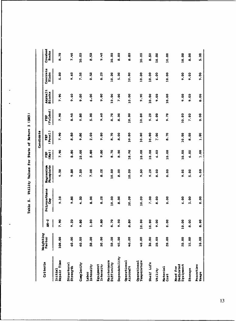
parts of Europe and examined. Analysis of this data COMPARISON OF ALTERNATIVESindicates that there is a probability of 0.15 that it may rain(rain is defined as moisture constituting more than 1 milli- After constructing the utility graphs, specific data re-meter) in any given 4-hour period in Europe. Therefore, garding each alternative were plotted onto the utility graphsfor SN2 (constant downpour, no CBR gas present, tern- to ubtain utility values. For example, under the FRP matperature range between 32 OF and 120 OF), the probability alternative, it was determined that the mats cost about $5of occurrence is estimated to be 15 percent. per square foot. These data were plotted onto the cost
utility curve and a utility value of 10 was obtained (see3. State of Nature 3 (SN3) - This state of nature is based Figure 23). For criterion, such as labor intensiveness (seeon the probability that the system may have to operate Figure 16), where there are no discrete values, subjectiveunder CBR conditions. CBR threat data was difficult to values were used that were obtained from a brainstormingobtain because some of the datd are classified. To keep this session. A value of ten is defined as extremely labordocument unclassified, the probability predictions were intensive (any RRR technique that is more labor intensivemade based on information provided by experts at the is unacceptable and will not be considered). A value ofNaval Civil Engineering Laboratory (NCEL). For SN3 zero is then considered to be ideal with very little labor(CBR gas present, dry conditions, temperature range be- required.tween -20OF and 120 OF), the probability of occurrence is Once the criteria data were plotted onto the utilityestimated to be 5 percent. graphs, utility values were obtained for all alternatives
under the three states of nature (see Tables 3 through 5).The weighted value for each criterion was then calculated
UTILITY MEASUREMENTS by multiplying the utility value by its relative weight (seeTables 6 through 8). The composite utility of each altema-
After defining and ranking the criteria, utility graphs tive, under the effects of various states of nature, is deter-were constructed for each criterion. This step is the prel- mined by adding the weighted utility values of all 15ude to measuring the utility or worth of each alternative on criteria (see Table 9). The decision rule for this analysis iseach criterion. Utility is defined as an alternative's value to choose the alternative that offers the highest compositeto the system based on each criterion. Utility graphs are utility across the three states of nature. Table 9 also showsused to graphically depict the preferences for the system. the final rankings obtained for each state of nature in
The utility graphs are represented by a two-dimen- parenthesis and the final rankings obtained for the com-sional X-Y plot. The X-axis represents the range of per- bined states of nature. A general summary of proceduresformance values possible for the criterion under considera- that were used for this analysis are described below:tion. The Y-axis represents the range of utility valuesassociated with various levels of criterion performance. 1. The criteria outlined earlier were ranked in order ofThe shape of the graph is then drawn based on preferences importance (using the Delphi technique) and each criterionover a set of values for each criterion. For example (see was assigned a weighted value.Figure 13), the utility graph for the criterion initial repairtime is an S-curve with change in curvature at 4 hours 2. Utility graphs were then developed (through the con-(increase in curvature after 4 hours), and 8 hours (decrease sensus of several NCEL experts) for each criteria.in curvature after 8 hours) on the X-axis. This indicatesthat for an initial repair time of from 0 to 4 hours, the value 3. Three states of nature were defined and a probabilityto the system is very high. The increase in repair time of occurrence was assigned to each state of nature.inside the 4-hour range (i.e., from 2 hours to 3 hours) is notseen as critically detrimental. However, any increase in 4. Specific data for each alternative (under three possiblerepair time after the 4-hour range is seen as a major set- states of nature) were then plotted onto the utility curves toback, thereby justifying the rapid decrease in utility in that obtain utility values.range. After the 8-hour range, the curve decreases in slopeindicating that the repair method after 8 hours is seen as a 5. Weighted utility values were obtained by multiplyingsemipermanent repair and additional decreases in time are the values obtained in step 4 by weighted values obtainednot significant to the emergency repair system. Utility in step 1. The following equation was used:graphs were constructed for all criterion under all thieestates of nature through a brainstorming session (see Ap- WUnij = Unij X Wipendix A for biainstorming definition) by several NCELexperts (personnel who have extensive background in RRR) where WUnij = weighted utility for alternative n under a(see Figures 13 through 57 for utility graphs). given criterion i and state of nature j
5

Unij = utility for alternative n under a given SENSITIVITY ANALYSIScriterion i and state of nature j
By comparing the final utility values for each alterna-Wi = weight for a given criterion i tive under the three states of nature, an alternative's sensi-
tivity to change in the environment can be determined.6. The composite utility for each state of nature was The system sensitivity analysis was performed by dividingobtained by summing all the weighted values for the crite- the composite utilities for state of nature 2 and 3 into theria. The following equation was used: composite utilities for state of nature 1. The deviation of
the resultant quotient from the ideal (a value of 1) is aCUnj = summation of WUnij, i = 1 to 15 direct measure of the alternative's sensitivity to change in
the environment For example, crushed rock has a finalwhere CUnj = composite utility for alternative n under value of 0.62 for SN2 compared to SN1, and 0.99 for SN3
state of nature j compared to SNI (see Table 10). This indicates that theeffectiveness of the crushed rock repair method is greatly
WUnij = weighted utility for alternative n under decreased by rain, however the presence of CBR has littlea given criteria i and state of nature j negative impact.
Sensitivity analysis was also performed on a criterion-7. The adjusted composite utility values were obtained by-criterion basis, rather than the "sum of criteria," to gainby multiplying the composite utility for each state of nature a more in-depth insight on what criteria are affected theby the probability of occurrence for that state of nature. most by change in the environment. Tables I1 and 12The following equation was used: show the results from the sensitivity analysis.
ACUnj = CUnj X P(SNj)COMMENTS AND CONCLUSIONS
where ACUnj = adjusted composite utility for alternativen under state of nature j Nine alternative techniques for repairing bomb dam-
aged airfields were examined and analyzed in this systemsCUnj = composite utility for alternative n under analysis. The procedures followed a systematic format that
state of nature j used analytic techniques to solve the problem. The analy-sis began by identifying and defining the problem, which is
P(SNj) = probability of occurrence for state of that the NCF lacks a capability to rapidly repair bomb-nature j damaged runways. Thus, the goal is to provide the NCF
with the most efficient and cost effective techniques to8. The final composite utility values were obtained by rapidly repair bomb-damaged runways. The alternativesadding the adjusted composite utilities for all three states were evaluated against criteria (evaluation factors) identi-of nature. The following equation was used: fled by experts at NCEL. The criteria were weighted based
on the relative importance of each criterion in achievingFCUn = ACUnl + ACUn2 + ACUn3 the overall goal. The final step was to develop a decision
rule to select the best alternative. In this analysis, thewhere FCUn = final composite utility for alternative n decision rule is to select the alternative which yields the
highest or maximum expected utility from the criteria.ACUnl adjusted composite utility for alterna- This is achieved by making a decision matrix of alterna-
tive n under state of nature 1 tives versus a list of evaluation factors derived from thecriteria for success.
ACUn2 = adjusted composite utility for altema- The decision matrix is a good presentation of thelive n under sate of nature 2 available RRR techniques and their value as overall RRR
systems in relation to each other. The following describesACUn3 = adjusted composite utility for alter- each alternative (with final utility values in parenthesis)
native n under state of nature 3 and how that alternative did when subjected to the criteria(evaluation factors) outlined earlier
6

1. Asphalt Blocks (5492) - Asphalt blocks scored the significantly more expensive, complex, and labor intensivehighest of all the alternatives. This repair technique ranked over the FRP mat. Lower scores were attained in theseconsistently high in all the categories and under all three categories compared to the mat.states of nature, indicating that it was not sensitive toenvironmental changes. Repairs using asphalt blocks are 6. Magnesium Phosphate (5092) - Magnesium phosphatefast, simple, and cost effective. Asphalt blocks can be scored consistently high in the majority ot the categories.easily stored, have long shelf life characteristics, and can It is a fast, structurally strong, and maintenance free repairbe used for peacetime applications. They are sensitive to technique. The problem is that it is complex and veryextreme hot temperatures and require two types of dedi- costly. It is doubtful that this technique could be madecated equipment (infrared heater and reclaimer). This simpler, however the cost could possibly be reduced. It hastechnique is still in the research phase and as more data limited peacetime applications and does not operate wellbecome available, it will be included in future editions of under extremely cold conditions. Sensitivity analysis indi-this report. cates that this repair is somewhat sensitive to rain.
2. FRP Mat (5276) - The FRP mat technique ranked 7. AM-2 Aluminum Matting (5089) - AM-2 matting scoredconsistently high in most of the categories. It is a proven consistently high in the majority of the categories. It is atechnique that is fast, simple, inexpensive, and has long proven technique that is fast and simple. AM-2 matting isshelf life characteristics. FRP mat performance is not easy to store, has indefinite shelf life, and is not sensitive toaffected by changes in temperature nor is it significantly environmental changes. The drawbacks of AM-2 mattingaffected by the presence of rain or CBR. The structural are that it is labor intensive, very expensive, and introducesstrength characteristics and maintenance requirements of an unacceptable roughness/bump criteria for some aircraft.the mats were rated slightly lower than most of the othertechniques. Since FRP mats have minimal applications in 8. Polyurethane Cap (4803) - Polyurethane cap repairpeacetime, they were given a low rating for this category. had a fluctuation of very high scores and very low scores.
It did extremely well in the repair time, strength, labor in-3. FRP Folded (5205) - The foldable FRP repair tech- tensiveness, and maintenance category since it is a fast,nique is almost identical to that of the FRP mat technique. structurally strong, and maintenance free repair. However,The concept is basically the same with the exception that it is the most complex and expensive of all the alternatives.the foldable mat is air transportable. The air transportabil- It is difficult to store, has limited shelf life, and, because ofity factor has increased the mat cost, increased the com- high costs, has no known peacetime applications.plexity, decreased the structural strength, and decreasedthe shelf life characteristics (due to the hinges). The 9. Concrete Slabs (4750) - The concrete slab techniqueslightly lower scores for the folded FRP compared to the did well in most of the categories. It is a structurallyFRP mat are a result of these changes. strong, easily maintained, and inexpensive repair that has
good peacetime applications. It scored poorly however,4. Crushed Rock (5195) - The crushed rock technique because in the categories that were weighted the heaviest,scored consistently high under SNI. For SNI, it has the it scored the least. It is a complex and very slow repairsecond highest score behind asphalt blocks. It is a very technique. It is extremely labor intensive and is heavilyfast, simple, and inexpensive repair technique with good dependent on doing each subtask correctly.peacetime applications. It is not labor or equipment inten-sive and is easy to maintain. However, when constant rain If the decision matrix is the only tool used for making(SN2) was introduced into the scenario, it faltered drasti- the decision, then the clear choice is asphalt blocks, withcally. Crushed rock repair cannot be used in rain because FRP mat as the second choice. Concrete blocks should notthe rain interferes with compaction, weakens the material, be considered at all. However, this analysis is based onand washes the fines away, thereby rendering the repair judgmental data from the author and selected experts whichineffective. Under dry conditions it is an excellent altema- reflect the background and experience of the author andtive; however, its sensitivity to environmental (rain) changes experts. Nevertheless, the values suggest that there is ahas decreased its rating from number two to four. clear cut winner, although each alternative has its partiiu-
lar advantages and drawbacks.5. FRP Panel (5182) - The FRP panel is almost identical The matrix suggests that asphalt block is the bestto the FRP mat technique. The concepts, attributes, and solution as it has all the advantages desired in the RRRdrawbacks are almost the same. The biggest difference is system. There are several alternatives which scored verythat the panels are designed to be air transported and bolted close to each other. In this case, the determining factortogether at the site. This factor has made the panels should not be the overall score, but the overall score in
7
combination with the sensitivity factor. If an alternative is It reflects the opinions of the author and leading RRRextremely sensitive, then accuracy of predictions plays an experts. This analysis is not intended to make the decisioneven more important role in this analysis. of which RRR syr'm to implement; it is merely a means, a
Other factois outside this analysis must also be consid- tool for NAVFAC to use for making a decision.ered. This analysis assumes that the scenario is at a fixed The analysis was conducted methodically and eachbase in the NATO arena. If this is not the case, then outside phase was carefully thought out. An emphasis was made tofactors play an even more important role. For example, if allow for changes in the input criteria. It is easy to retraceair transportability is a requirement, then only the altema- steps back through the analysis to see what factors wereti\ es which are air transportable can be considered, regard- included and what factors need to be changed (if neces-less of the benefits of the others. sary). Finally, it allows NAVFAC to be in a position to
A systems analysis has been performed on the RRR state clearly the procedures, factors, and rationale thatsystem. The analysis is based on a logical step-by-step were used for making the final decision.procedure of analyzing the smallest details of each system.

Table 1. Advantages and Disadvantages of Existing RRR Techniques
RRR RepairTechnique Advantages Disadvantages
FRP Mat Economical Mat size not easily changedLong shelf life
FRP Panel Low weight and cube storage ExpensiveAir transportable Labor intensiveLong shelf lifeCan be bolted together toform different dimensions
FRP Foldable Economical Hinges are unprovenMat Air transportable Mat size not easily changed
Magnesium Long shelf life ExpensivePhosphate Semipermanent repair Setting time difficult
Flush repair to controlPoor results in extreme coldSpecial equipment needed
Polyurethane Almost totally mechanized ExpensiveCap Semipermanent repair Complex system
Flush repair Special equipment neededToxic materialsDifficult to storeShort shelf life
Concrete Slabs Simple Slow repair timeGood peacetime applications Labor intensiveLong shelf life Equipmert intensiveEconomical Special equipment needed
Manual skill required
Asphalt Blocks Simple Special equipment neededGood peacetime applications Labor intensiveLong shelf lifeEconomicalSemipermanent repairFlush repair
Crushed Rock Simple Not effective in heavy rainEconomical Need high compaction effort
AM-2 Matting Long shelf life Labor intensiveReadily available in Expensivecurrent inventory Possible problem with matCan be assembled to form thickness (1-1/2 inch)different dimensionsAir transportableLow weight and cube storage
9

Table 2. Selected Criteria and Weighted Values
Criteria Value Percent
Deployment Time 100 16.4
Structural Strength 60 9.8(sorties supported prior tofirst repair)
Complexity 60 9.8
(level of skill required)
Labor Intensiveness 50 8.2
Equipment Intensiveness 50 8.2
Maintenance Difficulty 50 8.2
Dependency 45 7.4
Operational 40 6.6(under wide temperature range)
Operational 40 6.6
(under wide aircraft range)
Shelf Life 30 4.9
Utility 20 3.3(can material and equipment beused for other missions, i.e.,taxiways, ALRS)
Need for Dedicated Equipment 20 3.3
Material Cost 20 3.3
Storage 15 2.5
Peacetime Usage 10 1.6100
10

000 0 0 0 00
C, @o 0 Ol 0l 0 0o 0o 10U -' .4
4)
4br-4 0
0 0~0 0 0 0 0 0 0 0 0 0 0so. co~ 0 0 0 0 0 O 0 0 0 0~ 0~ 0
12I r4 co 07 0: I ;. ;C; 0 ; 0 :
o0 0 0 0 0 0 0 a 0 0 0 00 -ac 00 0 N 00 0 00 0
IL0 '. ci 0 : C 6 40 ,C
$4 P 0 0 0 0 00 0000 0 0 N 0 0 0 0 0 0ý 0 0 a
-. L. -i C6 4 :.466 1; 6 9 C ;
9 .. 40 0 0 0 0 a 0 0 Q 0 0 0 0 0 04b co) 0 0 0o N 0 0 0 0 0 0 0 0 0
0 6 C6 C; 4 *c 6 o 4 C; C .4.
ta
940
'44
-A m.49 0 030 0 0 0 0 0 0 0 0 0 0 0 04) A. No 0D 0 N 0 0 0 m N 0 0 0 0 a
t). o
0. . 0 0 0 a 0 0. 0. 0 0 0. 0 0on. 0 W 4 a
0- 0 0 0 0 0 0 0 0 0 0 0 0 0 0
Sn 0fl 0 0 0 0 0 0 0 0 0 04a 0' 0. . 0 0 0 a 0 0 N 0 0 0 0 0
14 H4 r4
V44 tot0S4N- 0.4.0 r .4
o *0 0 0 04 0 re
10 0 04 0 0 00 0 0ak. 0. 0 0 ' r. 0 0 0 0 0..4 r 0 04 0 0
u -. 4 a. 5 .4 -
Oh 4io o 0 9

A AC 0 0 0 0 0 0 0 0 0fA 0D0 00 0 OD W 00 0 00 0
84C: C 0 0; C 0 : C; 0 6 06 u 0 0 0A C; z 1ý U
41a M2 0 0 0 0 0 000 0 0 0 0 0 0MA 0 4 0 %D 0 0 0m 0 0 0 0 0 0
4~. -i 0: C6 6. C ;C 0
46
15. AC 0 0 0 0 0 0 0 0 0 0 a 0
As 14 -ý C4 C!C!C
*1' U
ci 0 0 0 00 0 0 0 0 0 0 0 0 0 0c.4 % t 0co. 0 0 0 C-i 0 0
4bt 0 0. 0~ 0' 0 0 0 0 0' 0 0' 0 0' 0
., IL -. C6 0: N z14C ý C ; ý C ; 1
4) 00d 4 4 0 0 0 0 0 0
0.4 0 .t 0 0 0 0 0 0 0 0 0 0 0
4) 0D 0 0 0 0o 0 0 0 0 0 0 0 0 0 0IL1 0 6 ; 0 i 0 z 0 ý N 6 0 ; 0 ; 0 ; 0; 00
t4 .4 14 V4 .
l6a0'44
I.15 0 0 0 0 00P?A .. 0 0 0 0 N 0 0 0 0 a 0 0 4 0 0 0
(A Ac No 0o N 0 N 0 0 0 . 0. 10 0 '0 0 '
>1
.4b
p1 0 0 0 0 0 0 0 0 0 0 0 0 0c)Ia. N 0o fn 0 N 0 0 0 0 0 0 0 0 0 0143 0: 0: .5 6 6 C; 0 6 0 ; 0 ; 0 z N 6 0 ; 0z 10
ci 4
15
N 0 0 0 0 0 0 0 0 0
N, 0o 0. Nl 0 Nl 0' 0 0 0 a. 0 0 Go 0D
*.r 4 0 0 0 0 0 0 0 0 0 0 a 0 0 0-P0 0 0 0 0 0 0 0 0 0 0 0 0 0
4441
4) to m4 .4 4c41l5- r54> cJ .4 1 15A 0cP 0el &
4b- V-M.A. r. 0 %4 .3O'> MP0.1 .41 5 'bk 'A E2 M1 40 44 P1 M P '4 4P4 Ma 4-..4 a.. DC M a.C r.P C pS '.4 $M 130 v5 4
-4 4bc C'r44 r4 0 +P V)4 -4)'.4'.4 4 0ibao .4. MM a.1 4) '40 .4 4112 0 VrCc 41 4b Ir r' 54 4 .. .) . P AQ 4 ~ 4
12
0 4 0 0. 0 0 O 0 0 a 0 0 0 0 a 40 U0U 4 A4 .4 NO LA N .400 0
0:1 ;4iC ;C; C : 0
to 0 a 0 0 0 0 0 C 0 0 0 0 0 0 0
t, 8 l Ol 1 0 0ý 0 0 0 o 0 0.0o 00
C, t) @ r 0 0 U 0 0 0 0 03
%t. ?1 a a 0 0a 0 0 0 0 , 0 0 0 0
L- 0) a 6 ý a A 0 6 06 0 C0 0ý 0 0ý a a, a
m .) 0 t 0 0 0 0. 0 0 0 0' 0 0 0 0 00L o- c0 O 0 co r. 0 0 0 a~ 0 N. 0 t
0 cc 04a a a 0 0 0 0 a 0 0 0 0 0 0 0
M Lco 0 Ul o c o 0 0 0 10- 0 0 a '
00
00
04.14
* *41 0 Q 0 0 00 a 00 0 0 0 0 00 aI.~ ) O L a a m a 00
I£5 0: %t. c O 0 0 o 0 a, go ' 0 a~ It) 0
0.
. A 4p
4a a 00 0 0 0 0 00ei L YIt M N
4). 4 0
4A .4 I -4.-4s A m 0-.b 0 n* P 4 0 1 6 h 4
r. 44- 4. t
313

El 0 a a a a a a a a 0 a a 0 0 0 00 00 0 0 0 0 N 0 In 0 0 0 0 0 .0
a a a a 0 0 0 0 0 0 0 0 0
G0l 0 0 0 0 0 0 8 0 0 0 a 0 0 8 0 00: g a a w 0 OD 14 a
4) 0 0 0 0 0 0 0 0 0 0 0 0 0 0 004A 0 0 0 0 0 0 0 C 0 a 0 0 0 0 0 0
1406 nL o o o 1". -4L t Lj n t M P
4*0 0 0 0 0 0 0 a 0 0 0 0 0 0 0 0 00l N 0 0 0 0 0 N 0 & a 0 0 0&L4 a00 10n 4NIt %t 'O "
bt.r4 4)
-0 a& a a a a a a a a a a a a a am A. a a a a a a a a a a a a a a a a.1 *.4 ILci0 l f a 0a 0 no a . acN N
r. 12 N It Nt in % N2- In
.4a 0 a a a a a a a a a a a a a a=9 0 0 a a a In a a ca a aa a hiLL N a A m~ Ao~ ea 0 N al ".4- nI so 1 Nt Nto .li wt to N
Ell
E4) ab a a a a a a a a a a aG~. a 0 c a a a a a a a0 0 Cr.G Ln n .4 ao %t N..
toý "0% 't Into.
Inn
54 .A a a a a a a a a a a a a a a a a
94 - . '
c 0 0 a a a a a a a a a a a a a a01 aQ N 0 0 a N a a a a a a 0 N.4LIn~ n 0. In a 0 a N cow~~~ In "z .4 . o t t 4 4.
In
%t co co N N Nl 10 so 'a PA mo rA In 'a a
r..
a1 a a a a a a a a a a a a
0 a s N N .4 4
El1 E P *.'I 4 444 . 4 4)1' OC 4 44 I~4)C4 .4 4 40 4$.4 Nw 0d .4 4) G) 44. .0 0a 04) 4.4 04) *. 4 S V 4 4C l 44 IL~ .4 r 4 4 v"4 Erlb 4 mu Al 34-) 2 W'a -4)4Id
14

a a a a a a a a a a a a a 0 0
c;g g 6 a 4 ma ai6 6 c c ;N0 %0 .0 54 54 co " L
UN A
a a a a a a a a a a a a a a a aFAs 0 a a a a a a a a a a a a 0 0 0
e 00 a Nm cl 0f%t L n N %t mM . N
M a a 0o a am aw 0 0 0 00~ 1 a , 00 n c
in% bMM Me.. 5 V
LL 0 soi 0 N~ Nn 0 a0*.6 U. N mm 4 .~t 5.4 . NA
d) a a a a a a a 0
31 a !;
'4b
Nn a, 'a so
4D
a a a a0 a a a a a a a 0
a C. a a% a a a a Cam4
W0a.
a mm N a a aa ao 00N .4 Nt m0 a aA 0 0 ao
Ln %t It .4Nt40
It OD c N wl N st 0 a a, 54 fn m V '0aM '0 -Z 0: C6 C6 C6 N 0 ' r 4 45 4 .
A 0 r-4
r4 54 0 0 0 0 0 0 0
A.4
ra4 a a a; a; a; a; a; a; a; a a aa a
m asom a o a
-. 4 .4.M
V4 V1 .4 U 4 r.-41. 3.. 04 05464 m F4 A 00 V .I
Ua 4b Z4 A.A 94. 44M l44 C M $4N 0. 4 G4)4 a.14 0 .,L 2 .4 44J 01
"4IL4 64Y (3 24 I-41 IL 01 &I- th.J -A 46 0 U) A
15

0 0 0 0 0 0 0 0 0 0 00 0 0n 0 a 0 N 0 0A 0 0 0 0 0 So
0 o A 0 0 0 0 U)
.J 0 0 0 0 0 0 0 a 0 0 0 0 0 0 0 0'A6 0 0 0 0 0 a 0 0 0 0 0 0 0 0 0 084 A
Mu L)A * UN W- co
00 0 0 0 0 0 0 0 0 0 0 0 0 0 0
.44 00 0 0 0 0 0 0 0 0 0 0 0 0 0 0
0.10m ix 4 C;C ; L ; C ;C j C
..4 04 3 0 0 0 0 0 0 0 0 0 0 0 0 0 0 0 0
4)1 i 0 0 0 0 0 0 0 0 0 0 0 0 0 0 0 0
0 00 0 0 0 0 U0oo~ ~ 0U 04) 030 O 0 0 04'L 13. fA uCj~-l N -
- 0 00 0 0 0 0 0 0 0 0 0 0 0 0 0.A 0 0 0 0 0 0 0 0 0 0 0 0 0 0 0 0c~ 0 040 N v4 C
54 0 0 0 0 0 0 0 0 0 0 0 0 0 0 0 00 4A4, 0 0 0 0 0 0 0 0 0 0 0 0 0 0 0 0
-4~~8 08 -
0 0 0 0 0 0 0 0 0 0o 0 a0 0 0 0
54 A 0 0 04 0 0 0n 0n 0 0 0 0 0 0 0 0lol 4, 0A 0l 0M 0 0 0 0 0I 40 0
ci %t 0o 0o W N .3.tso a O f nL
r3.-H 1 0 0 0 0 0 0 0 0 0 a a 0 0 0* N 0 0 a 0 0 0 0 0 0 0 0 0 0 0 0 0
A 4)~'m 0. -A V.3. n l N) N3 1-
A ~ ~ ~ > 40 r. .,I. 0 0 3 ) N N) N -'34. A 0 N N .3 .0 0 M "I N) N Ugo 034
48 4-4)44 . -
144J5 0 0 IL. 0 0 0 0 0 0 0 04 -0 0. 0 0,a.0 0 0 84 01 0S60 0 0 04 0 0 0ý 0 01
m :c g I x1:1L .0
161

Table 9. Rank Total with SNI, SN2, and SN3 Ranks
SNI SNI SN2 SN2 SN3 SN3 Total Total
Candidate 80% Rank 15% Rank 5% Rank 100% Rank
Asphalt Blocks 4424.0 (1) 798.0 (1) 269.5 (2) 5491.5 (1)
FRP (Mat) 4250.4 (3) 766.9 (2) 258.7 (3) 5276.0 (2)
FRP (Folded) 4193.6 (4) 756.3 (3) 255.1 (4) 5205.0 (3)
Crushed Rocks 4408.8 (2) 513.4 (9) 272.3 (1) 5194.5 (4)
FRP (Panel) 4180.0 (5) 750.2 (4) 251.8 (6) 5182.0 (5)
Magnesium Phosphate 4103.2 (7) 733.4 (6) 255.0 (5) 5091.6 (6)
AM-2 4105.6 (6) 736.2 (5) 247.1 (7) 5088.9 (7)
Polyurethane Cap 3848.8 (8) 715.7 (7) 238.1 (8) 4802.6 (8)
Concrete Slabs 3828.8 (9) 695.4 (8) 225.6 (9) 4749.8 (9)
Final Score Calculation:
Asphalt Blocks = 5530 (0.80) + 5320 (0.15) + 5390 (0.05)
- 4424 + 798 + 269.5 = 5491.5
17

Table 10. Sensitivity Analysis
Alternative SN1 SN2 SN3 SN2/SNI SN3/SN
Asphalt Blocks 5530.00 5320.00 5390.00 0.96 0.97
FRP (Mat) 5313.00 5113.00 5173.00 0.96 0.97
FRP (Folded) 5242.00 5042.00 5102.00 0.96 0.97
Crushed Rocks 5511.00 3423.00 5446.00 0.62 0.99
FRP (Panel) 5225.00 5001.00 5035.00 0.96 0.96
Magnesium Phosphate 5129.00 4889.00 5099.00 0.95 0.99
AM-2 5132.00 4908.00 4942.00 0.96 0.96
Polyurethane Cap 4811.00 4771.00 4761.00 0.99 0.99
Concrete Slabs 4786.00 4636.00 4511.00 0.97 0.94
18

Cu
0~ @t o O 0 0 0 0 a 0 0 0 0 C 0 N'
$4 A c 0 0 LA 0 . 0 -4 - 0 .4 0 0 a 4 .- 0
14)?(d 0 0 0 a 0 0 0 % 0 0 0 0 00 0NAI a a 9 n 9 C a C! a! a9 aa a00
a. 0 . 0 .4 l 44 4 0 4 0 4 .4 0 - - 0
r4
a a 0n a a a a a a a1&~8U4 a N 0 co 4 0 .4 4 44 0 0 .4 .4 0
No
m )0 0 0 0 a 0. a 0 a a a a a a a0 a a 0 0 a a a a a a %a a a o
a 0~ a . a 4 0 .0 4 .4 .4 .4 0 0 0 o
N4 %.4 C 0. a N 0 al a a a a a a a a %D
N C ~0 0 .4 0 .4 0 .4 . .4 4. . a
.44
* i a . >4 a > 4 44.
4.s~ a a a a a a0 a a0 a4 a a a ak aD6 m a) .4 a.4u .04 0 1 1
W '
CnA5,
.19

A O 0 0 0 0 0 0 0 00 0 0 0 0 0 oS
OS 0 08 0 0 0 0 000 0 0 4 0
4D44I M 4 0 0 £ 0 0 0 0 0 0 0 0 084. A r 0 0 C. 0 0 0 0 0 0 0 0 0 8
a.- 0 0 a 4 0 4 0 4 .4 .4 .4 0- 0 0
0 00 00 0 0 0 8 0 0 Nl0 o o 00 88888 0 0 00 a C0oS
0
44 0 0 0 00 :0 00 0 0
88~0 0 0 0 0 0 0 0 0 0 a 0 t,
0 04 00 0 0 0000
-A M.4 N 0 0 0 0 0 0 0 0 0 0 0 0 0 0 oSA * oS 0 0 0 0 0 0 0 0 0 0 0 0 0 0 oS
bO
I-I
41a.0 0 0 0 0 0 0 0 0 0 0 0 0 0 0.
00
14£
* ~ 4b 4)44.4 ag ~ .144 *1 4 m 1 4 04£4 41. 45 404 40 14 4 . 14!44 th -PA4 4*4 r4 8 S .4
u *a. -P 04 U 01
20

Viji
Figure 1, Rolling FRP laminate to expel trapped air
21

"..........
Figure 3. FRP panels ready for traffic.
22

Figure 4. Placing foldable FRP mat.
Figure 5. Foldable FRP mat ready for traffic.
23

Figure 6. Placing concrete slabs inside crater.
24

Figure 7. Placing asphalt concrete blocks inside crater.
Figure 8. Compacting asphalt concrete blocks.
25

Water upplyGrout P~owderWater Supply
Water317L
Bag Splitter Additives
iRotating Pan MixerSBilades
Grout
Discharge
Hoses
Figure 9. Schematic view of grout mixer system.
26

~ 10 1
-~-Sk
Figure 10. Roln rse*tn wt irtr olr
Figure 10. Sroaying crushredtoane weith vibsdratoyrler.
/2
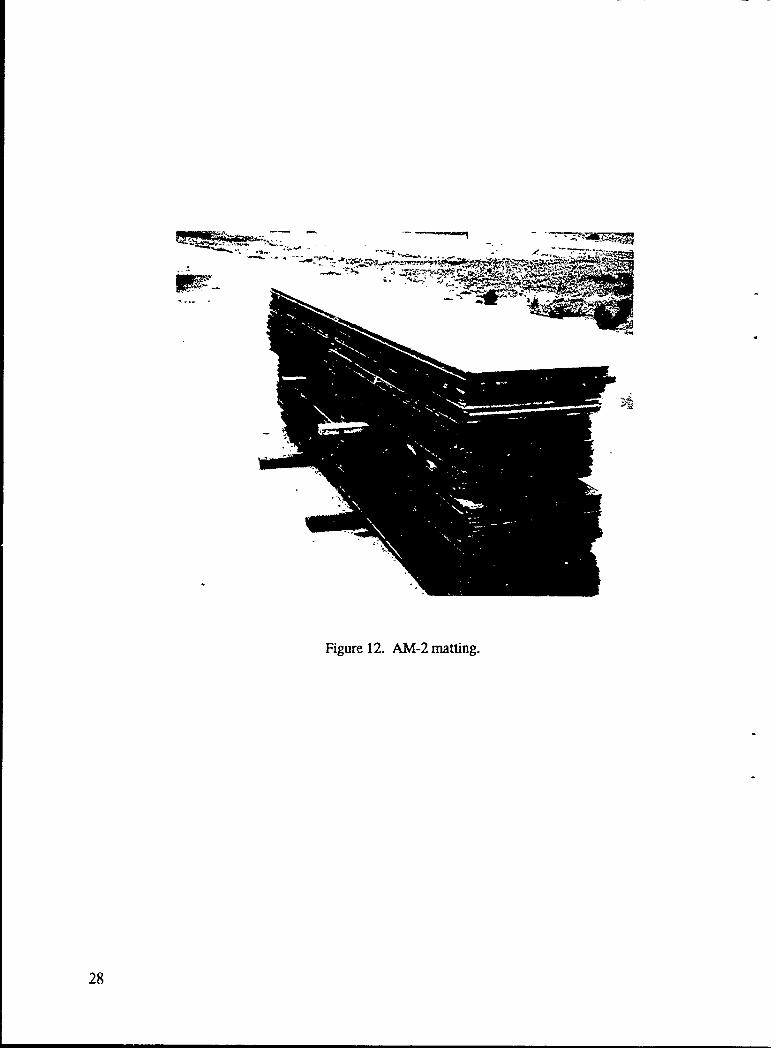
Figure 12. AM-2 matting.
28
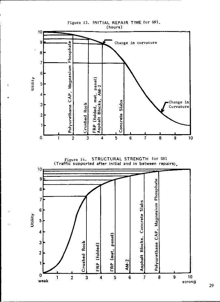
Figure 13. INITIAL REPAIR TIME for SNI.(hours)
10
SChange in curvature
8"0
7 CL_ _
E
66- m
4 -<U E u; Change i
3 - 0 U 6 Curvature2 0
o -V -06.
1 0.
j L U-
0 1 2 3 4 5 6 7 8 9 10
Figure 14. STRUCTURAL STRENGTH for SN1(Traffic supported after initial and in between repai rs).
10
9
0 '-C
* • 1< U; ia100
7- a.:.a
.2 I
0~~~-- 1 6 7 8 9 1
929
4; U
8 0..
00 0-
M 340 di
44 m
z ~ 0. C
00.ý - A - - - 0
1 2 7 8 9 1w e a k
s r o n g 2

Figure 15. COMPLEXITY for SNi.
10_
9
8
7 0a..
6 w a:LL
E5 X 0
4-. u. C
'A U3 u0 3)
0ipl.Cmpe
2 -
10 00
6-- - E
0 1 3 5 6 7 8 9 10
So-Implsie Compexsv
10
8 'W -_0
0
006 - 3 7 8 9 1
Non-Itensie Intnsiv
300

Figure 17. DEPENDENCY for SNi.(On Prior Procedures)
10MC
9 0.
8 "
6""
5
4
" 0 0
2-
fn 0CL U I0 1 2 3 4 5 6 7 8 9 10
Non- Related Dependent
Figure 18. OPERATIONAL for SNl(Under Wide Temperature Range). -•
10 _ _ _ _ _ _ _ _ _ _ _
9 "o
8in U
70 -
6 • -S0
5 -0 W
, C.4 .C= s 0
0 • .UU
2 .2*3 0-Eu0
0 1 2 3 4 5 6 7 8 9 10narrow wide
31
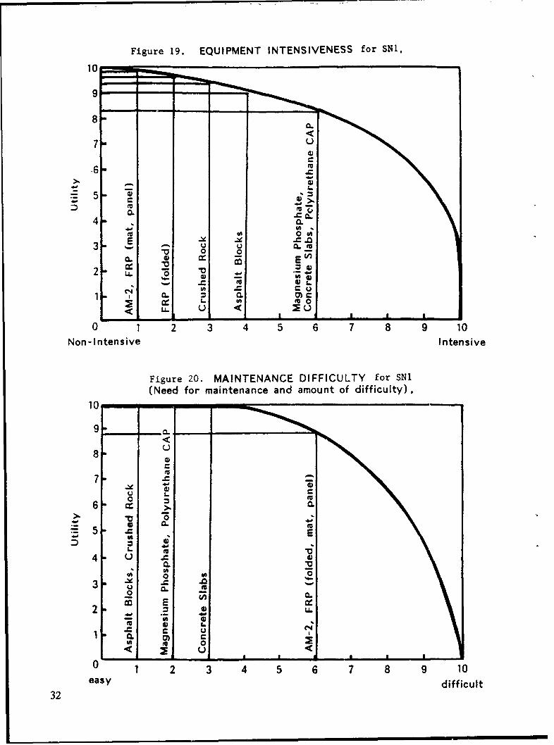
Figure 19. EQUIPMENT INTENSIVENESS for SN1.
10
9 -- " - - -
8-=
7 U
.6 o
4.-
2- - L... " ,0.0
EI =,= =3 - U CL ,1 0 0
2 16 0
No-)nt-sveIneniv
10C
8 0< w U ~U
"- -0 1 2 3 4 5 6 7 8 9 10
Non-Intensive Intensive
Figure 20. MAINTENANCE DIFFICULTY for SNi(Need for maintenance and amount of difficulty)
10
9
8. U
7-)U
6 -0.
5 MuE
4 U £4
0.
0 Cu
00
Cu <
- -s- -1aa --0 I 2 3 4 5 6 7 8 9 10
32 easy difficult

Figure 21. OPERATIONAL for SNi(Types of Aircraft Supported),
10-
9
8
7 10
6-
5 m CU
U Cu 00
U 0
8 • _.._.
2 U
7 m•
'C
0 1 2 3 4 5 6 7 8 9 10none all
Figure 22. SHELF LIFE (YEARS) for SMi,
10
9.
.0
7VAo
U6 a.
E 0U
-04 C
3 0
2 C<
1 E 0.
24 6 8 10
33

Figure 23. COST ($/sq. ft.) for SNi,
100
'- 5
UU..
4.
00CC 4
2
0.c
U' i, - U.• LL I
2 4 •6 8 10 12 14 16 18 20 22
Figure 24. STORAGE for SN1.10 0
9
7
6 4
oLL
0 0.
--4 U C
0 UU
3 "--- U, - =0o E
-2- - 0
MM 00. 0.
0 1 2 3 4 5 6 7 8 9 10
easy difficult34

Figure 25. UTILITY for SNi.
10"-
CL
EU8"0
7-
6>. 0C.
5-S 0
Z .0. 04m
U, 0.0 0.
3 Cf. 6 8 E
Lo UiltyHih tiit
E 00
7 ..-
L0-.
UE
C .a
0 1 2 3 4 5 6 7 8 9 10Low Utility High Utility
Figure 26. NEED FOR DEDICATED EQUIPMENT for SNi.(Different Types of Dedicated Equip -nt)
101
0
.105 -
CL
0EU
0 0
LA. < 0m
2 3, 4'5
35

Figure 27. PEACE TIME USAGE for SNi.
10
9
8
CL
7-U4)
>0.
4 0 '
00C
CL 0
1 IL 0
I. Ud I< Ud
0 1 2 3 4 5 6 7 8 9 10
None Always
36

Figure 28. INITIAL REPAIR TIME for SN2,(hou rs)
100
9~~
4
4~ CL
1 __ __ _ __ __<_
p~ 0
Fiue2.SRUTRLSRNGH-rS2(Traffic~~~~~~~ supote afe'ntaladi ewenrpis
=- 0
CL 0
44 ofLL< U
10U
9..
0.0
6 2 8 9 1
wea 4 5-sZ 3

Figure 30. COMPLEXITY for SN2.
101-4
9
8 -! __,,__
. - 0.7 0 0
6
E -
5m 1-
U042 0
Fiur 31. LABO INESVNSSfrS
U; U3 y~-0
U <'0 0
L -U Cd
100
9.
8•
7•
4. 66 -- - --0 0
2 -=
2 M
I- 0
0• 1 t 1 'L a
o 1 2 3 4 5 6 7 8 9 10
Non-Intensive Intensive
38

F;ure 32. DEPENDENCY for SN2.
(On prior procedure)
10
8 - -•_6 '= Mo6 DE
7 w- 0 0
-0 =6%.
5L6
4-
EU
r_ 0
2
0 . 0CL U U
1L < = a'=- - -•
0 1 2 3 4 5 6 7 8 9 10Non- Related Dependent
Figure 33. OPERATIONAL for SN2.
(Under wide temperature range)
10 , -
9-
8
.0 -
rfl C-V)
6 L..U• I
5 C E
00 U L
VI
0 0E a 0aC:
L...".
2 W LL
M WU
U < .I , I I I __ __ __ _
0-------0 1 2 3 4 5 6 7 8 9 10narrow wide
39

Figure 34. EQUIPMENT INTENSIVENESS for SN2.
10
9- -
8C
70,
6-4.' --
M0.
4 S04 2 . {
0. 0
2~~ U..
0 1 2 3 4 5 6 7 8 9 10Non- Intensive Intensive
Figure 35. MAINTENANCE DIFFICULTY for SN2.
(Need for Maintenance and Amount of Difficulty)
10
9-U)
0-
7) -- C4) ZU5" L.>. JXj
5 -Z E
o 0.L
3 C. . U
'U
0 - 1 a
2 2 3 4 5 6 7 8 9 10
easy difficult
40

Figure 36. OPERATIONAL for SN2.(Types of Aircraft Supported)
10"
9
8
m 3000 U
3- 0I -
ro.
2- - U 0
0_
-CL U.o
3L .£l ) . Lu
LL
1 01 .t .=•
0 1 2 3 4 5 6 7 8 9 10
nonle all
Figure 37. SHELF LIFE (YEARS) for SN2.
10
0.
'UU
E U4 m
U
3 0 0
1U 0. CL0
2 4 1
41

Figure 38. COST ($/sq. ft.) for SN2.
10 .
9 0.
EE
8 -4 6 8 1 1 4 1 1 0 2
5-A
44
2 -m
0.
7
1. 0 C-)4
4 U. LL
L ,. 43,CI,.
0.0
4 6 8 10 12 14 16 18 20 22
Figure 39. STORAGE for SN2
10
9
8
7-;
(U
0- 0
5 UL<
0 U33 -
U0 I
00
CC 43 - -
o 0 CL
242

Figure 40. UTILITY for SN2.
<
8L w - .Ui i t.
7I
S5
4ý .0.0
0 0
9i*00
00 I4 I
Low Utility High Utility
Figure 41. NEED FOR DEDICATED EQUIPMENT for SN2.(Different Types of Dedicated Equipment)
10 ,
9:8"
° ~7-'0 =
"5
4 M U
V;LL 0"*.., ~ .. < ,
'U
0o
1 2 3 45
43

Figure 42. PEACE TIME USAGE for SN2.
10
9
78
CL7<
'U
3-C_6.0.
U- -- .=CL CLa CD
3 U
0AL. 0
2 -- <
0 1 2 3 4 5 6 7 8 9 10
None Always
44

Figure 43. INITIAL REPAIR TIME for SN3.(hours)
10
8 m-
7-
6-
6 00
.W 50 i
u.<o o4 m 0. C l
0 U W
a 0 04
0 0.CL
0 1 2 3 4 5 6 7 8 9 10
Figure 44. STRUCTURAL STRENGTH for SN3.
Traffic supported after initial and in between repairs
10
9
84'
8~0.
7 ftC.
650
0
4-. U
4 m U 0.
zi i0: 0: 0
1 3 4 8 9 1
2e k trn
* E -45

Figure 45. COMPLEXITY for SN3.
100401
9 E
>.,L
J 0.7 1 0 7 81
&00
CL
UU
63 -----5-- 5:4
0 c
1A
0 2 3 4 5 6 7 8 9 10
-iur "6. LAO NESVEESfrS
No - ne -ire____tensi_
86
4 C.
U 03
2 -
200
01 2 3 4 5 6 7 8 9 10SonImplsie Compexsv
464

Figure 47. DEPENDENCY for SN3.(On Prior Procedures)
100
9 0.
.4.
7 *~0.SOw
6E
5LLc
4 (A
2 0 II
3-~3 1 07a10MU 0:
2z
'M I-I
(U L.
CR
0 1 2 3 4 5 6 7 8 9 0
Non -Related Dependent
Figure 48. OPERATIONAL for SN3.(Under Wide Temperature Range)
1079-
8CL
7-
6 (UM
5 -. (U
*00*
3 U'
20 LL.
(U
22 0 U
0 3 4 5 6 7 8 9 1narrow wide
U, .647

Figure 49. EQUIPMENT INTENSIVENESS for SN3.
100
9C7 U
6...
CL60.
0.
o 0
C. .0 1 2 3 4 5 6 7 8 9 10
Non- Intensive Intensive
Figure 50. MAINTENANCE DIFFICULTY for SN3•(Need for maintenance and amount of difficulty)
109 ".
9l i~0 -
8 -
0
CL
7 7
6 o Eu
6 0.L. -.
0.
2 2 4 5 6 .9 14.., , 10
easy48 difficult

Figure 51. OPERATIONAL for SN3.(Types of Aircraft Supported)
8
mo 0
0 CA. = ,;
4 1 2 3 5 6 7 8 1
0 03
u4
6 YI%. -"m E
= ,.,
U~2
0 CC•
0 1 2 3 4 5 6 7 8 9 10none all
Figure 52. SHELF LIFE (YEARS) for SN3,
10
800
'U
CL C
6 0
E' U
4 -<U.
U
-V10. E
C. U <A
24 6 8 10
49

-0
Eu
10 0 2a.--
8-am~0)
7
6U
5 _E
4 LL
01 o30u- 0-
0. 0
0 LL I6U U -L --- J
2 4 6 8 10 12 14 16 18 20 22
Figure 54. STORAGE for SN3.
10
9
8
6 a-CAEu
.0 0.
2 U.U -
o EE
00
1 2~ 3 4~ 5 8 9 1
50 eas diffcul

Figure 55. UTILITY for SN3.
10
9.
8
0.
S5
4 '' EE
0 c) '
0 1 2 3 4 5 6 7 8 9 10
Low Utility High Utility
Figure 56. NEED FOR DEDICATED EQUIPMENT for SN3.
(Different Types of Dedicated Equipment)
10
0
0
0
6 ,
4 cc a0. .<
3 C X -M C. 0
o -o C
S.
0 1 2 3 4 5
51

Figure 57. PEACE TIME USAGE for SN3.
10 0
9-
7 m<€,
6w•
5-U
c00
~2" 3 lu
CL m00
None Always
52

Appendix A
USING DELPHI ANALYSIS AND BRAINSTORMING AS PROBLEMSOLVING TECHNIQUES FOR RAPID RUNWAY REPAIR (RRR)
DELPHI TECHNIQUE tions. Again, if their answers fall outside the 50th percentilerange, an explanation is required. This process continues
The criteria defined in the rapid runway repair (RRR) until the coordinator feels that there is sufficient informationsystems analysis was ranked using the Delphi technique. This to make a conclusion (usually four questionnaires). Thetechnique is similar to brainstorming, except that the people results are summarized and presented. Tables A-1 to A-3involved are not physically together at a meeting place, but show the three questionnaires that were sent out in the RRRinstead work separately. The first step is for the coordinator systems analysis.to select a panel of experts with some background in theproblem area. The coordinator then prepares a questionnairethat is relevant to the problem. The questionnaire is sent to BRAINSTORMINGeach participant for answers. Upon receipt of the answers, thecoordinator analyzes the results and determines the median This technique was used in the RRR systems analysis toand 50th percentile values. A second questionnaire (identical generate a consensus of opinion for developing the threeto the first) is then sent out asking the same questions, except states of nature that the system may have to operate in. It wasthis time the median and 50th percentile answers are shown also used to develop the utility graphs and utility values fornext to each question. The participants are asked to recon- each alternative. Brainstorming brings together (physically)sider each answer in view of the results from the first a group of knowledgeable rcople in a particular subject areaquestionnaire. If their second response is outside the 50th and allows an interchange of ideas. It is used for planning,percentile, they are asked to provide reasons for their an- developing ner, proposals, and solving complex problems.swers. The answers to the questionnaire are again analyzed The intent is to provide an atmosphere for free discussionby the coordinator and the new median and 50th percentile with no inhibition of ideas. Following the brainstormingvaluet are calculated. A third questionnaire is sent out session, the coordinator examines the ideas and suggestions(showing the results of the second questionnaire) asking the and selects the most reasonable and promising to be pre-participants to answer the questions taking into account the sented.previous answers and arguments for or against specific ques-
A-1

Table A- 1.Questionnaire 1 for RRR Delphi Analysis
Memo
From: L64IChang
To: NCEL RRR Experts
You have been identified as a present/past rapid runway repair (RRR) expert. This is the first of three questionnairesthat I am asking you to answer for my RRR systems analysis. Please rate the following criteria with respect to howimportant you feel each criterion is when selecting a rapid runway repair technique. Thanks for all the help.
Task: Rate and assign importance values for each criterion listed below.
Start by selecting the least important criterion and assign an importance value of 10. Then consider the next leastimportant Lriterion and decide how much more important (if at all) it is than the least important. If four times as importantthen assign 40, if twice as important then assign 20, etc. Continue this process until all the criteria are rated.
Criteria Value
Material cost
Initial repair time
Operational (under wide temperature range)
Labor intensiveness
Equipment intensiveness
Complexity (level of skill required)
Shelf life
Peacetime usage
Structural strength (sorties supported prior to first repair and in between repairs)
Maintenance difficulty (difficulty to make repair after initial sorties)
Note: Please make comments on the criteria (i.e., any criterion that should be added to the list, deleted from the list, etc.).
Additional Criteria Value Deletions
1.
2.
3.
Comments:
A-2
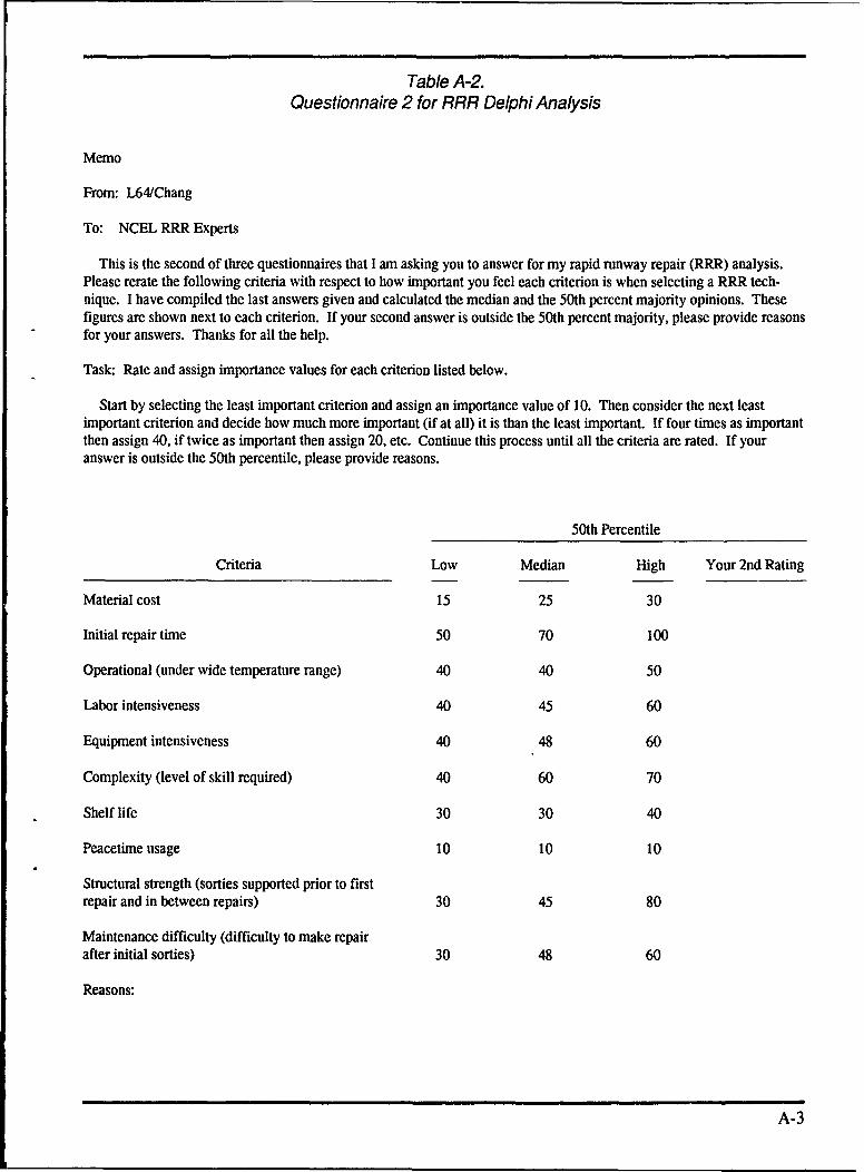
Table A-2.Questionnaire 2 for RRR Delphi Analysis
Memo
From: L64/Chang
To: NCEL RRR Experts
This is the second of three questionnaires that I am asking you to answer for my rapid runway repair (RRR) analysis.Please rerate the following criteria with respect to how important you feel each criterion is when selecting a RRR tech-nique. I have compiled the last answers given and calculated the median and the 50th percent majority opinions. Thesefigures are shown next to each criterion. If your second answer is outside the 50th percent majority, please provide reasonsfor your answers. Thanks for all the help.
Task: Rate and assign importance values for each criterion listed below.
Start by selecting the least important criterion and assign an importance value of 10. Then consider the next leastimportant criterion and decide how much more important (if at all) it is than the least important. If four times as importantthen assign 40, if twice as important then assign 20, etc. Continue this process until all the criteria are rated. If youranswer is outside the 50th percentile, please provide reasons.
50th Percentile
Criteria Low Median High Your 2nd Rating
Material cost 15 25 30
Initial repair time 50 70 100
Operational (under wide temperature range) 40 40 50
Labor intensiveness 40 45 60
Equipment intensiveness 40 48 60
Complexity (level of skill required) 40 60 70
Shelf life 30 30 40
Peacetime usage 10 10 10
Structural strength (sorties supported prior to firstrepair and in between repairs) 30 45 80
Maintenance difficulty (difficulty to make repairafter initial sorties) 30 48 60
Reasons:
A-3

Table A-3.Questionnaire 3 for RRR Delphi Analysis
Memo
From: L64/Chang
To: NCEL RRR Experts
This is the third and final questionnaire that I am asking you to answer for my rapid runway repair (RRR) analysis.Please rerate the following criteria with respect to how important you feel each criterion is when selecting a RRR tech-nique. I have compiled the last answers given and calculated the median and the 50th percent majority opinions. Thesefigures are shown next to each criterion along with --guments against the majority opinions. If your third answer is outsidethe 50th percent majority, please provide reasons for your answers. Thanks for all the help.
Task: Rate and assign importance values for each criterion listed below.
Start by selecting the least important criterion and assign an importance value of 10. Then consider the next leastimportant criterion and decide how much more important (if at all) it is than the least important. If four times as importantthen assign 40, if twice as important then assign 20, etc. Continue this process until all the criteria are rated. If youranswer is outside the 50th percentile, please provide reasons
50th Percentile
Criteria Low Median High Your 2nd Rating
Material cost 20 20 25
Initial repair time 70 83 100
Operational (under wide temperature range) 40 43 50
Labor intensiveness 40 55 60
Equipment intensiveness 40 48 50
Complexity (level of skill required) 45 60 70
Shelf life 30 30 30
Peacetime usage 10 10 10
Structural strength (sorties supported prior to firstrepair and in betwve~en repairs) 40 55 70
Maintenance difficulty (difficulty to make repair afterinitial sorties) 30 48 60
A-4

Arguments: 4. Complexity 90 - In an emergency, may have only cooksand clerks available.
1. Peacetime use 20- If peacetime use is available, then it cutsdown on dependence of other factors such as shelf life, 5. Shelf Life 100 - If too short, you can be assured materialcomplexity (workers will already be experienced). will be no good when needed (such as life boats during the
WWII Wolf Pack Submarine attacks).2. Material cost 10 - Cost is inconsequential compared toaircraft cost. Reasons your answer is below 50% majority opinion:
3. Equipment intensiveness 70 - Equipment intensiveness isextremely important in Marine Corps and Navy, such asKefluvik, where additional equipment may be needed.
A-5

DISTRIBUTION LIST
CBC Code 155. Port Hueneme, CA: Library. Davisvillc, RI. PWO (Code 40X0). Gulfport. MS. PWO (Code 80).Port Hueneme. CA; PWO. Davisville. RI; Tech Librar,. Gulfport., MS
CG FMF Pac. SCIAD (G5) Camp HM Smith. HICOMFAIR Med. SCE, Naples, ItalyCOMNAVAIRSYSCOM Code 422. Washington. DCDTIC Alexandria. VAMARCORBASE PWO. Camp Pendleton. CAMCAS Code 6EDD. Iwakuni. Japan: El Toro. Code IJD. Santa Ana. CA: PWO. Kaneohe Bay. HI:., PWO.
Yuma. AZMCRDAC AW. Quantico, VA; SSE. Quantico. VANAS Code 072E, Willow Grove. PA.. Code 110. Adak. AK, Code 163. Keflasik. Iceland. Code 710, South
Weymouth. MA: Code 83. Patuxent River., MD: PWO (Code 182) Bermuda. PWO, Keflavik, Iceland:PWO. Sigonella. Italy: PWO, South Weymouth. MA: SCE. Barbers Point, HI
NAVAIRDEVCEN Code 832. Warminster. PANAVAIRENGCEN PWO. Lakeihurst. NJNAVAIRTESTCEN PWO. Patuxent River. MDNAVAMPHIB BASE Naval Amphib Bae - LC. Norlolk. VANAVCONSTRACEN CO. Port Hueneme. CANAVFACENGCOM Code 03. Alexandria. VA. Code 06. Alcxandria. VA. Code 0631. Alexandria. VANAVFACENGCOM - CHES DIV. FPO-IPL. Washington. DCNAVFACENGCOM - LANT DIV. Code 1632. Norfolk, VANAVFACENGCOM . NORTHl DIV. Code 04AL., Philadelphia. PANAVFACENGCOM PAC DIV. Code 405, Pearl Harbor. HI; Code 4106. Pearl Harbor. HI, Library. Pearl
Harbor, HINAVFACENGCOM - SOUTH DIV. Library. Charleston. SCNAVFACENGCOM - WEST DIV Code 04A2.2 (Lib). San Bruno. CANAVSUPPACT PWO. Naples. ItalyNCR 20. CO; 20, Code R70NMCB 40, CONSC Cheatham Annex, PWO. Williamsburg, VAPWC Code 421 (Kaya), Pearl Harbor. HI. Library (Code 134). Pearl Harbor, HI. Library, Norfolk, VA;
Library, Pensacola. FL; Library, Yokosuka, Japan

INSTRUCTIONS
The Naval Civil Engineering Laboratory has revised its primary distribution lists. The bottom of the
label on the reverse side has several numbers listed. These numbers correspond to numbers assigned to
the list of Subject Categories. Numbers on the label corresponding to those on the list indicate the
subject category and type of documents you are presently receiving. If you are satisfied, throw this card
away (or file it for later reference).
If you want to change what you are presently receiving:
0 Delete - mark off number on bottom of label.
. Add - circle number on list.
* Remove my name from all your lists - check box on list.
S Change my address - line out incorrect line and write in correction (DO NOT REMOVE LABEL).
e Number of copies should be entered after the title of the subject categories you select.
Fold on line below and drop in the mail.
I: Note: Numbers on label but not listed on questionnaire are for NCEL use only, please Ignore them,
,, Fold on line and staple
DEPARTMENT OF THE NAVY II INaval Civil Engineering LaboratoryPort Hueneme. CA 93043-5003Official Business NECESSARYPenalty for Private Use, $300 IF MAILEDIN THE
UNITED STATES
BUIEI-REPLY CARD____FIRST CLASS PERMIT NO. 12503 WASH D.C. JPOSTAGE WILL BE PAID BY ADDRESSEE
Commanding OfficerCode L34Naval Civil Engineering LaboratoryPort Hueneme, California 93043-5003

"'DISTRIBUTIONdUftT~iON'NAIRE- - -I
The N&aval Civil Engineering Laboratory is re•vinrg Its Primary'distribution lists.
SUBJECT CATEGORIES 28 ENERGY/POWER GENERATION29 Thermal conservation (thermal engineering of buildings. HVAC
1 SHORE FACILITIES systems, energy loss measurement. power generation)2 Construction methods and materials (including corrosion 30 Controls and electrical conservation (electrical systems,
control, coatings) energy monitoring and control systems)3 Waterfront structures (malntenance/deterioratior. control) 31 Fuel flexibility (liquid fuels, coal utilization, energy !4 Utilities (including power conditioning) from solid waste)5 Explosives safety 32 Alternate energy source (geothermal power, photovoltaic6 Aviation Engineering Test Facilities power systems, solar systems, wind systems. energy storage7 Fire prevention and control systems)8 Antenna technology 33 Site data and systems integration (energy resource data. I9 Structural analysis and CGesign (Including numerical and energy consumption data, integrating energy systems)
computer techniques) 34 ENVIRONMENTAL PROTECTION10 Protective construction (including hardened shelters, 35 Hazardous waste minimization
shock and vibration studies) 36 Restoration of Installations (hazardous waste) I11 Soil/rock mechanics 37 Waste water management and sanitary enginijering14 Airfields and pavements 38 Oil pollution removal and recovery
39 Air pollution15 ADVANCED BASE AND AMPHIBIOUS FACILITIES 'I16 Base facilities (including shelters, power generation, water 44 OCEAN ENGINEERING I
supplies) 45 Seafloor soils and foundations17 Expedient roads/airfields/bridges 46 Seafloor construction systems and operations (including 'I18 Amphibious operations (including breakwaters, wave forces) diver and manipulator tools)19 Over-the-Beach operations (including containerization, 47 Undersea structures and materials
material transfer, lighterage and cranes) 48 Anchors and moorings20 POL storage, transfer and distribution 49 Undersea power systems, electromechanical cables,
and connectors50 Pressure vessel facilities51 Physical environment (including site surveying)52 Ocean-based concrete structures54 Undersea cable dynamics
TYPES OF DOCUMENTS85 Techdata Sheets 86 Technical Reports and Technical Notes 82 NCEL Guides & Abstracts 0 None- n83 Table of Contents & Index to TDS 91 Physical Security remove my name