Embed Size (px)
Citation preview

This content has been downloaded from IOPscience. Please scroll down to see the full text.
Download details:
IP Address: 157.193.98.234
This content was downloaded on 11/06/2015 at 14:02
Please note that terms and conditions apply.
Upgrade of the CMS muon system with triple-GEM detectors
View the table of contents for this issue, or go to the journal homepage for more
2014 JINST 9 C10036
(http://iopscience.iop.org/1748-0221/9/10/C10036)
Home Search Collections Journals About Contact us My IOPscience

2014 JINST 9 C10036
PUBLISHED BY IOP PUBLISHING FOR SISSA MEDIALAB
RECEIVED: June 14, 2014ACCEPTED: July 28, 2014
PUBLISHED: October 23, 2014
INTERNATIONAL CONFERENCE ON INSTRUMENTATION FOR COLLIDING BEAM PHYSICS
BUDKER INSTITUTE OF NUCLEAR PHYSICS, NOVOSIBIRSK, RUSSIA
FEBRUARY 24 – MARCH 1, 2014
Upgrade of the CMS muon system with triple-GEMdetectors
D. Abbaneo,o M. Abbas,o M. Abbrescia,b A.A. Abdelalim,h M. Abi Akl,m W. Ahmed,h
W. Ahmed,q P. Altieri,b R. Aly,h A. Ashfaq,q P. Aspell,o Y. Assran,g I. Awan,q S. Bally,o
Y. Ban,c S. Banerjee,s P. Barria,e L. Benussi,n V. Bhopatkar,v S. Bianco,n J. Bos,o
O. Bouhali,m S. Braibant,d S. Buontempo,x J. Cai,c C. Calabria,b C. Caputo,b
F. Cassese,x A. Castaneda,m S. Cauwenbergh,p F.R. Cavallo,d A. Celik,i M. Choi,ae
K. Choi,ae S. Choi,ac J. Christiansen,o A. Cimmino,p S. Colafranceschi,o A. Colaleo,b
A. Conde Garcia,o M.M. Dabrowski,o G. De Lentdecker,e R. De Oliveira,o
G. de Robertis,b S. Dildick,i,p,1 B. Dorney,o W. Elmetenawee,h G. Fabrice,aa S. Ferry,o
P. Giacomelli,d J. Gilmore,i L. Guiducci,d A. Gutierrez,l R.M. Hadjiiska,ab
A. Hassan,h J. Hauser,u K. Hoepfner,a M. Hohlmann,v H. Hoorani,q Y.G. Jeng,r
T. Kamon,i P.E. Karchin,l H. Kim,r S. Krutelyov,i A. Kumar,k J. Lee,ae J. Lee,ae
T. Lenzi,e L. Litov,ab F. Loddo,b T. Maerschalk,e G. Magazzu,z M. Maggi,b
Y. Maghrbi,m A. Magnani,y N. Majumdar,s P.K. Mal, f K. Mandal, f A. Marchioro,o
A. Marinov,o J.A. Merlin,o N. Mohammed,k A.K. Mohanty,w A. Mohapatra,v
S. Muhammad,q S. Mukhopadhyay,s S. Nuzzo,b E. Oliveri,o L.M. Pant,w P. Paolucci,x
I. Park,ae G. Passeggio,x B. Pavlov,ab B. Philipps,a M. Phipps,v D. Piccolo,n
H. Postema,o G. Pugliese,b A. Puig Baranac,o A. Radi,g R. Radogna,b G. Raffone,n
S. Ramkrishna,k A. Ranieri,b C. Riccardi,y A. Rodrigues,o L. Ropelewski,o
S. Roychoddhury,s M.S. Ryu,r G. Ryu,ae A. Safonov,i A. Sakharov, j S. Salva,p
G. Saviano,n A. Sharma,o S.K. Swain, f J.P. Talvitie,o, C. Tamma,b A. Tatarinov,i
N. Turini,z T. Tuuva,t J. Twigger,v M. Tytgat,p I. Vai,y M. van Stenis,o R. Venditi,b
E. Verhagen,e P. Verwilligen,b P. Vitulo,y U. Yang,ad Y. Yang,e R. Yonamine,e
N. Zaganidis,p F. Zenonie and A. Zhangv
aIII Physikalisches Institut A, RWTH Aachen University, Aachen, GermanybPolitecnico di Bari, Universita di Bari and INFN Sezione di Bari, Bari, Italy
1Corresponding author.
c© CERN 2014 for the benefit of the CMS collaboration, published under license by IOP Publishing Ltdand Sissa Medialab srl doi:10.1088/1748-0221/9/10/C10036
2014 JINST 9 C10036
cPeking University, Beijing, ChinadUniversity and INFN Bologna, Bologna, ItalyeUniversite Libre de Bruxelles, Brussels, Belgiumf National Institute of Science Education and Research, Bhubaneswar, IndiagAcademy of Scientific Research and Technology, ENHEP, Cairo, EgypthHelwan University & CTP, Cairo, EgyptiTexas A&M University, College Station, U.S.A.jKyungpook National University, Daegu, KoreakUniversity of Delhi, Delhi, IndialWayne State University, Detroit, U.S.A.
mTexas A&M University at Qatar, Doha, QatarnLaboratori Nazionali di Frascati - INFN, Frascati, ItalyoCERN, Geneva, SwitzerlandpDepartment of Physics and Astronomy, Ghent University, Ghent, BelgiumqNational Center for Physics, Quaid-i-Azam University Campus, Islamabad, PakistanrChonbuk National University, Jeonju, KoreasSaha Institute of Nuclear Physics, Kolkata, IndiatLappeenranta University of Technology, Lappeenranta, FinlanduUniversity of California, Los Angeles, U.S.A.vFlorida Institute of Technology, Melbourne, U.S.A.wBhabha Atomic Research Centre, Mumbai, IndiaxINFN Napoli, Napoli, ItalyyINFN Pavia and University of Pavia, Pavia, ItalyzINFN Sezione di Pisa, Pisa, Italy
aaIRFU CEA-Saclay, Saclay, FranceabSofia University, Sofia, BulgariaacKorea University, Seoul, KoreaadSeoul National University, Seoul, KoreaaeUniversity of Seoul, Seoul, Korea
E-mail: [email protected]
ABSTRACT: The CMS collaboration considers upgrading the muon forward region which is partic-ularly affected by the high-luminosity conditions at the LHC. The proposal involves Gas ElectronMultiplier (GEM) chambers, which are able to handle the extreme particle rates expected in thisregion along with a high spatial resolution. This allows to combine tracking and triggering capa-bilities, which will improve the CMS muon High Level Trigger, the muon identification and thetrack reconstruction. Intense R&D has been going on since 2009 and it has lead to the developmentof several GEM prototypes and associated detector electronics. These GEM prototypes have beensubjected to extensive tests in the laboratory and in test beams at the CERN Super Proton Syn-chrotron (SPS). This contribution will review the status of the CMS upgrade project with GEMsand its impact on the CMS performance.
KEYWORDS: Micropattern gaseous detectors (MSGC, GEM, THGEM, RETHGEM, MHSP, MI-CROPIC, MICROMEGAS, InGrid, etc); Electron multipliers (gas)

2014 JINST 9 C10036
Contents
1 Introduction 1
2 The CMS GEM project 2
3 Gaseous electron multipliers 2
4 Impact on trigger and physics impact at the high-luminosity LHC 34.1 Trigger 34.2 Physics 4
5 R&D for CMS GEM project 45.1 Early GEM prototypes 45.2 Large GEM prototypes 45.3 GEM foil stretching 55.4 Aging tests 55.5 Chamber construction and quality control 65.6 Data acquisition and electronics 6
6 Integration into CMS 7
7 Conclusions and outlook 7
1 Introduction
The Compact Muon Solenoid [1] at the Large Hadron Collider [2] is designed to detect muonsand measure its properties with excellent precision. The muon system consists of 3 comple-mentary gaseous muon detection technologies for triggering and tracking purposes. Drift Tubesare instrumented in the barrel region (|η | < 1.2), Cathode Strip Chambers in the endcap region(|η |> 1.2), and Resistive Plate Chambers in barrel and endcap up to |η |< 1.6. The high eta region,1.6 < |η | < 2.4 is only instrumented with CSCs. The ongoing Phase-I muon upgrade during the1st Long Shutdown (LS1) includes the completion of the 4th endcap station with CSCs and RPCsup to |η |< 1.8. The expected upgrade of the LHC during LS3 (∼ 2022) to achieve
√s = 7TeV and
L = 5× 10⁻³⁴ cm−2 s−1 will yield a large increase in the particle rate, especially for the endcaps.A L1 trigger system for the silicon tracker will not be installed until LS3. CMS will need addi-tional handles to cope with the high rate of particles between LS2 (∼ 2018) and LS3. The high-ηregion offers a nice opportunity to install additional muon detectors in the currently vacant posi-tions. Naturally, such detectors have to satisfy a high rate capability, Ω(1MHz/cm2), a good timeresolution for triggering, and a good spatial resolution, Ω(100 µm), for tracking. The current CMSRPC design is not able to sustain the high rates. However, there are various solutions in the field ofmicro-pattern gaseous detectors (MPGDs), namely gaseous electron multipliers (GEMs) [3].
– 1 –

2014 JINST 9 C10036
2 The CMS GEM project
The baseline of the CMS GEM project is the installation of 36 double-layered triple-GEM cham-bers in front of the ME1/1 station during LS2, called the GE1/1 system. The chambers will pro-vide full coverage in φ and 1.55 < |η | < 2.18 in pseudo-rapidity. The even-numbered GE1/1chambers will be slightly larger to maximize coverage in |η |. The station 2 upgrade (GE2/1) con-sists of installing two rings of double-layered triple-GEM chambers during LS3 covering up to1.6 < |η |< 2.45. Each GE2/1 chamber spans about 20 degrees in φ . The third part of the projectis a muon near-tagger (ME0) with 18 six-layered triple-GEMs, with each chamber providing cov-erage of 20 degrees in φ and 2.0 < |η |< 3.5 in pseudo-rapidity. The geometry of both GE2/1 andME0 is yet to be finalized. The location of the proposed GE1/1 and GE2/1 in the present CMSMuon system is shown in figure 1.
0 2 4 6 8 10 12 z (m)
R (m
)
1
0
2
3
4
5
6
7
8
1 3 5 7 9 115.0
4.0
3.0
2.52.42.32.22.12.0
1.9
1.8
1.7
1.6
1.5
1.4
1.3
1.2
1.00.9 1.10.80.70.60.50.40.30.20.140.4°44.3° 36.8°48.4°52.8°57.5°62.5°67.7°73.1°78.6°84.3°
0.77°
2.1°
5.7°
9.4°10.4°11.5°12.6°14.0°15.4°
17.0°
18.8°
20.7°
22.8°
25.2°
27.7°
30.5°
33.5°
θ°η
θ°η
ME4
/1
ME3
/1
ME2
/1
ME1
/2
ME1
/1
ME2
/2
ME3
/2
ME1
/3
RE3
/3
RE1
/3R
E1/2
MB1
MB2
MB3
MB4
Wheel 0 Wheel 1
RB1
RB2
RB3
RB4
HCAL
ECAL
Solenoid magnet
Silicon tracker
Steel
RE2
/2
Wheel 2
RE2
/3
RE3
/2M
E4/2
RE4
/3R
E4/2
GE1
/1 GE2
/1
DTsCSCsRPCsGEMs
Figure 1. Transverse section of CMS showing the present Muon system with DTs, CSCs and RPCs. Theproposed GEM stations, GE1/1 and GE2/1, are given by the red boxes. ME0 is not shown.
3 Gaseous electron multipliers
GEMs are a type of MPGDs constructed from a resistive polyimide foil with a thickness of typically50 µm, layered between 2 conductive layers (usually copper) with a thickness of about 5 µm. Thefoil is perforated with a hexagonal pattern of (bi)conical holes, with a typical hole diameter of70 µm and a pitch of 140 µm. The foils themselves are produced using a Printed Circuit Board(PCB) manufacturing technique. Many years of R&D at CERN have made the production of largescale areas (1× 2m2) cost-effective, enabling the design and testing of CMS-scale prototypes.GEMs have an excellent spatial and time resolution, Ω(100 µm) and ∼ 5ns respectively. Theyhave a high efficiency (up to 98%) and a high rate capability Ω(1MHz/cm2). In addition, theyare radiation hardened and can be operated with a non-flammable gas mixture of Ar/CO2/CF4
(45/15/40), which makes GEMs ideal material for a triggering-tracking detector. At CERN, GEMshave been succesfully used at other experiments (LHCb, COMPASS and TOTEM) in which therewas no significant loss of performance, even after many years in operation [4].
– 2 –
2014 JINST 9 C10036
4 Impact on trigger and physics impact at the high-luminosity LHC
4.1 Trigger
The expected increase of the LHC beam instantaneous luminosity from the design luminosity of1034cm−2 s−1 to maximally 5× 1034 cm−2s−1 in the Phase-II era will have a big impact on theMuon endcap system, in particular the high-η region. Many more soft particles will scatter offelastically in the muon detectors and in the particular in the iron return yokes. Multiple scatteringcauses straightening of the tracks. Low-pT muons are misinterpreted as high-pT muons by the CSCTrack-Finder, resulting in a flattening of the trigger rate curve at high-pT. To reduce the trigger ratewhile maintaining high efficiency, one needs to install an additional muon detector (GEM) thatmeasures the bending angle in station 1. The extra measurement points will also yield a higherefficiency, even at scenarios with up to 140 interactions per bunch crossing (pileup).
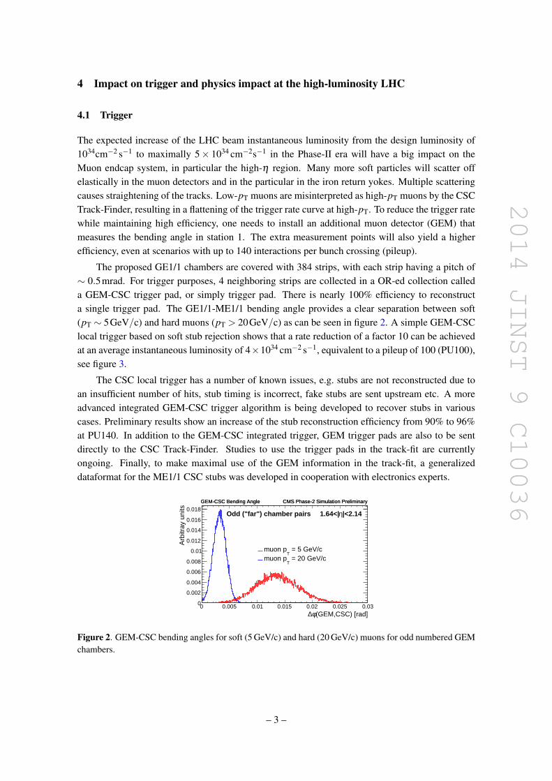
The proposed GE1/1 chambers are covered with 384 strips, with each strip having a pitch of∼ 0.5mrad. For trigger purposes, 4 neighboring strips are collected in a OR-ed collection calleda GEM-CSC trigger pad, or simply trigger pad. There is nearly 100% efficiency to reconstructa single trigger pad. The GE1/1-ME1/1 bending angle provides a clear separation between soft(pT ∼ 5GeV/c) and hard muons (pT > 20GeV/c) as can be seen in figure 2. A simple GEM-CSClocal trigger based on soft stub rejection shows that a rate reduction of a factor 10 can be achievedat an average instantaneous luminosity of 4×1034 cm−2 s−1, equivalent to a pileup of 100 (PU100),see figure 3.
The CSC local trigger has a number of known issues, e.g. stubs are not reconstructed due toan insufficient number of hits, stub timing is incorrect, fake stubs are sent upstream etc. A moreadvanced integrated GEM-CSC trigger algorithm is being developed to recover stubs in variouscases. Preliminary results show an increase of the stub reconstruction efficiency from 90% to 96%at PU140. In addition to the GEM-CSC integrated trigger, GEM trigger pads are also to be sentdirectly to the CSC Track-Finder. Studies to use the trigger pads in the track-fit are currentlyongoing. Finally, to make maximal use of the GEM information in the track-fit, a generalizeddataformat for the ME1/1 CSC stubs was developed in cooperation with electronics experts.
(GEM,CSC) [rad]φ∆0 0.005 0.01 0.015 0.02 0.025 0.03
Arb
itray
uni
ts
0
0.002
0.004
0.006
0.008
0.01
0.012
0.014
0.016
0.018 GEM-CSC Bending Angle CMS Phase-2 Simulation Preliminary
= 5 GeV/cT
muon p = 20 GeV/c
Tmuon p
|<2.14η1.64<|Odd ("far") chamber pairs
GEM-CSC Bending Angle CMS Phase-2 Simulation Preliminary
Figure 2. GEM-CSC bending angles for soft (5 GeV/c) and hard (20 GeV/c) muons for odd numbered GEMchambers.
– 3 –

2014 JINST 9 C10036
2 3 4 5 6 7 8 910 20 30 40 50 210
Tri
gg
er r
ate
[kH
z]
-210
-110
1
10
210
310
410 CMS Phase-2 Simulation Preliminary
L1 Single Mu (2012 configuration) + ME1/1a unganging3 stubs (anywhere)≥CSC 3 stubs (one in Station 1)≥CSC
GEM+CSC integrated trigger3 stubs≥with
-1 s-2 cm34L = 4*10
| < 2.14η1.64 < |
CMS Phase-2 Simulation Preliminary
[GeV/c]cut
TL1 muon candidate p
2 3 4 5 6 7 8 910 20 30 40 50 210
Rat
io
-210
-110
1
(GEM+CSC)/L1 Single Mu3 stubs (one in Station 1)≥(GEM+CSC)/CSC
ηL1 muon candidate 1 1.2 1.4 1.6 1.8 2 2.2 2.4
Tri
gg
er r
ate
[kH
z]
1
2
3
4
5
6
7
8 CMS Phase-2 Simulation Preliminary
20 GeV/c):≥T
L1 Selections (L1 muon candidate p
3 stubs (anywhere)≥CSC
3 stubs (one in Station 1)≥CSC
3 stubs≥GEM+CSC integrated trigger with
-1 s-2 cm34L = 4*10
GE-1/1 region
CMS Phase-2 Simulation Preliminary
ηL1 muon candidate 1 1.2 1.4 1.6 1.8 2 2.2 2.4
Rat
io
-210
-110
1
3 stubs (one in Station 1)≥(GEM+CSC)/CSC
Figure 3. Left: comparison of the trigger rates vs pcutT for the Global Muon Trigger in the 2012 configuration
and various CSC Track-Finder configurations. Right: comparison of the rates vs η for various CSC Track-Finder configurations.
4.2 Physics
For physics purposes, the GEMs can provide extra leverage on precision studies of standard modelphysics, as well as open up a window to explore exotic signatures with muons in the high-η region.On standard model physics, GEMs can provide a more precise measurement of the HVV couplingsthrough H → ZZ → 4µ and H to WW decays, and of the Hff couplings through H → 2µ andWH→ νµττ . Interesting exotic signatures include B0
s → µµ , Z′→ µµ , W ′→ µν and µ∗→ µγ .
5 R&D for CMS GEM project
5.1 Early GEM prototypes
R&D on GEM detectors for CMS started with the RD51 collaboration in 2009. Various small10× 10cm2 prototypes (10× 10cm2) with varying geometries, different etching techniques andreadout configurations were considered and tested [5].
The major project achievements include the measurement of the single GEM efficiency of∼ 98%, the time resolution of 4ns, a spatial resolution of 290 µm with a VFAT2 (digital) and< 110 µm APV (analog) readout. GEMs have been succesfully operated in a magnetic field, at theCERN SPS, and at FNAL. A gas mixture of Ar/CO2/CF4 (45/15/40). In addition, the single masktechnology has been proven to be equally effective as the double-mask GEMs.
5.2 Large GEM prototypes
Several large GEM prototypes (∼ 1×2m2) have been developed since 2009 [6, 7]. The first largeGEM prototype, GE1/1-I, had all components glued together, had spacers and 8 readout sectors.The number of readout sectors was increased in GE1/1-II to 24. GE1/1-III was the first type to
– 4 –
2014 JINST 9 C10036
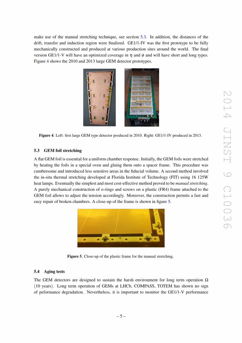
make use of the manual stretching technique, see section 5.3. In addition, the distances of thedrift, transfer and induction region were finalized. GE1/1-IV was the first prototype to be fullymechanically constructed and produced at various production sites around the world. The finalversion GE1/1-V will have an optimized coverage in η and φ and will have short and long types.Figure 4 shows the 2010 and 2013 large GEM detector prototypes.
Figure 4. Left: first large GEM type detector produced in 2010. Right: GE1/1-IV produced in 2013.
5.3 GEM foil stretching
A flat GEM foil is essential for a uniform chamber response. Initially, the GEM foils were stretchedby heating the foils in a special oven and gluing them onto a spacer frame. This procedure wascumbersome and introduced less sensitive areas in the fiducial volume. A second method involvedthe in-situ thermal stretching developed at Florida Institute of Technology (FIT) using 16 125Wheat lamps. Eventually the simplest and most cost-effective method proved to be manual stretching.A purely mechanical construction of o-rings and screws on a plastic (FR4) frame attached to theGEM foil allows to adjust the tension accordingly. Moreover, the construction permits a fast andeasy repair of broken chambers. A close-up of the frame is shown in figure 5.
Figure 5. Close-up of the plastic frame for the manual stretching.
5.4 Aging tests
The GEM detectors are designed to sustain the harsh environment for long term operation Ω
(10 years). Long term operation of GEMs at LHCb, COMPASS, TOTEM has shown no signof peformance degradation. Nevertheless, it is important to monitor the GE1/1-V performance
– 5 –

2014 JINST 9 C10036
with integrated charge collection to ensure long term operation, understand material degradationand propose solutions to counter it. To this end, gamma irradiation tests using 662 photons from137Cs source (566 GBq) are ongoing at the CERN GIF and are planned at the GIF++ lab [8].
5.5 Chamber construction and quality control
The GEM chamber construction procedure has been optimized over the past couple of years. Theassembly itself contains 3 major steps. The first step is the preparation of the drift board. The PCBis equiped with metallic inserts and HV probes, and is fixed to an outer frame. The second stepis the prepartion of the GEM stack. Three GEM foils are sandwiched in between platic frames.In the final step the GEM stack is placed on top of the drift board. The electrical contacts andHV divider are installed, after which the chamber is closed with the readout PCB. Finally, thegas in- and outlets are inserted. With the help of the manual stretching and the purely mechani-cal construction the procedure has optimized to take less than 2 hours instead of ∼ 1 week withthe gluing principle. The chamber construction is followed by a standardized quality procedure.During 2013 6 GE-IV prototypes have been built at various sites: INFN Frascati, INFN Bari, FIT,CERN, UGent and BARC.
5.6 Data acquisition and electronics
The GEM readout electronics is divided into the on-chamber and off-chamber electronics, as can beseen in figure 6. On-chamber, the GE1/1 detector prototype are first subdivided in 8 eta partitions.Each eta partition is further subdivided in 3 readout sectors along φ . Each sector is covered with 128readout strips which form the inputs to the 30 front-end ASIC (VFAT3 chip) via a connector on theGEM readout board (GEB). An Optohybrid board plugs into the GEB which contains the GigabitTransceiver chip set, a Field programmable Gate Array, and optical receivers and transmitters toprovide 2 optical paths to the off-detector electronics. The first path sends the fixed latency triggerdata from the GEMs to the CSCs. The second path is bidirectional and runs between the µTCA(micro Trigger Control and Acquisition) crates in the counting room and the optohybrid. It is usedfor sending set-up and control signals to the front-end chips.
Figure 6. Schematic overview of the on- and off-detector electronics for the GEM chambers.
– 6 –

2014 JINST 9 C10036
6 Integration into CMS
With the prospective of the full installation of GE1/1 during LS2, a slice test will take place duringthe Year-End Technical Stop of 2016. A small number of fully working GE1/1 chambers will beinstalled in one of the endcaps with a total coverage from 10 to 20 degrees. In preparation of theslice test, 3 dummy chambers (exact dimensions and weight, but no electronics) were producedduring May 2013. The subsequent trial installation of the dummy chambers during the Summer of2013 (figure 7) allowed the technicians to work out the cable routing, layout of the cooling pipes,hardware infrastructure etc. A new series of dummies, based on updated chamber dimensions,were produced during winter 2014, see figure 8. A new trial installation will take place before theend of LS1.
Figure 7. Left: location of the GE1/1 slots in the Muon endcap nose. Right: insertion of the dummychambers.
Figure 8. New version of dummy chambers according to long and short baseline.
7 Conclusions and outlook
The R&D for the CMS GEM project started almost 5 years ago (2009) with the RD51 Collabora-tion at CERN. Since then, triple-GEM technology has matured enough to satisfy the physics andtrigger needs for CMS in the post-LS2 era. The present GE1/1-V type is fully compliant with therestrictions for installation in the cavern. A partial approval for the installation of the GE1/1 systemwas obtianed during Summer 2013. Currently, CMS GEM collaboration is preparing a TechnicalDesign Report for GE1/1 by October 2014. The production of the finalized GE1/1-V detectors isscheduled for 2014–2015. During the Year-End Technical Stop of 2016-2017, a slice test will takeplace involving a small number of GEM super chambers installed in YE1/1.
– 7 –

2014 JINST 9 C10036
Acknowledgments
We acknowledge the support from the RD51 collaboration and CERN.
References
[1] CMS collaboration, The CMS experiment at the CERN LHC, 2008 JINST 3 S08004.
[2] L. Evans and P. Bryant, LHC Machine, 2008 JINST 3 S08001.
[3] F. Sauli, GEM: A new concept for electron amplification in gas detectors, Nucl. Instrum. Meth. A 386(1997) 531.
[4] A. Cardiniet et al., The Operational Experience of the Triple-GEM Detectors of the LHCb MuonSystem: Summary of 2 Years of Data Taking, IEEE Nucl. Sci. Symp. Conf. Rec. 2012 (2012) 759;B. Ketzer, Status of the PixelGEM Detectors, COMPASS Technical Board Meeting (2011),unpublished;B. Ketzer et al., A fast tracker for COMPASS based on the GEM, Nucl. Phys. Proc. Suppl. 125 (2003)368.
[5] D. Abbaneo et al., Characterization of GEM Detectors for Application in the CMS Muon DetectionSystem, IEEE Nucl. Sci. Symp. Conf. Rec. 2010 (2010) 1416 [arXiv:1012.3675].
[6] D. Abbaneo et al., Construction of the rst full-size GEM-based prototype for the CMS high-η muonsystem, IEEE Nucl. Sci. Symp. Conf. Rec. 2010 (2010) 1909, RD51 Note 2010-008[arXiv:1012.1524].
[7] M. Tytgat et al., Construction and Performance of Large-Area triple-GEM Prototypes for FutureUpgrades of the CMS Forward Muon System, IEEE Nucl. Sci. Symp. Conf. Rec. 2011 (2011) 1019,RD51 Note 2011-012 [arXiv:1111.7249].
[8] D. Abbaneo et al., The status of the GEM project for CMS high-η muon system, Nucl. Instrum. Meth.A 732 (2013) 203.
[9] P. Vichoudis et al., The Gigabit Link Interface Board (GLIB), a exible system for the evaluation anduse of GBT-based optical links, 2010 JINST 5 C110167.
– 8 –


![arXiv:2008.11593v1 [physics.flu-dyn] 26 Aug 2020Leidenfrost drop impact on inclined superheated substrates Yujie Wang, 1Ayoub El Bouhali, Sijia Lyu,1, a) Lu Yu,2 Yue Hao,1 Zhigang](https://img.pdfslide.us/doc/110x75/60a019800331832c6c10d612/arxiv200811593v1-26-aug-2020-leidenfrost-drop-impact-on-inclined-superheated.jpg)