Embed Size (px)
Citation preview
October 20, 2021
Updating the SiD Detector concept
M. Breidenbach and T. MarkiewiczSLAC National Accelerator Laboratory, 2575 Sand Hill Road, Menlo Park, CA, USA
J.E. BrauDepartment of Physics, University of Oregon, Eugene, OR 97403, USA
P. BurrowsDepartment of Physics, Oxford University, Oxford, UK
M. StanitzkiDESY, Notkestrasse 85, 22607 Hamburg, Germany
J. StrubeUniversity of Oregon, Institute for Fundamental Science, Eugene, OR 97403-5203
A.P. WhiteUniversity of Texas Arlington, Arlington, TX 76019, USA
The SiD Detector is one of two detector designs for the future International Linear Collider (ILC)that were validated in 2012 SiD features a compact, cost-constrained design for precision Higgsand other measurements, and sensitivity to a wide range of possible new phenomena. A robustsilicon vertex and tracking system, combined with a five Tesla central solenoidal field, providesexcellent momentum resolution. The highly granular calorimeter system is optimized for ParticleFlow application to achieve very good jet energy resolution over a wide range of energies. With apotential construction date of the ILC moving closer, it is now the time to review the design andtechnology decision that have been made during the DBD phase and reconsider them in the light ofthe recent technological advances. For each area of SiD development R&D topics and opportunitiesfor participation will be discussed.
I. INTRODUCTION
The International Linear Collider (ILC) [1] is aproposed e+e− collider at the energy frontier. TheILC is a 20 km long linear accelerator using super-conducting cavities with a initial baseline center-of-mass energy of 250 GeV. The ILC will provide polar-ized beams for both electrons (80%) and positrons(30%), which is a unique capability of linear collid-ers. The ILC project includes a clear upgrade pathto center-of-mass energies of 1 TeV, or even slightlybeyond. The ILC has a mature baseline design whichhas been summarized in the Technical Design Report(TDR), which was presented in 2012 [2, 3].
The ILC environment is unique and very differ-ent than at synchrotrons. The ILC accelerates abunch train with 1300 bunches roughly 550 ns apartroughly every 200 ms, so collisions only happen dur-ing 1 ms followed by a quiet time of 199 ms. Thisallows to buffer the data on the front-ends, read outat the end of the bunch train and then to power
down the front-ends (power-pulsing). This reducesthe average power consumption by roughly a factorof 100.
SiD started as a detector concept for linear col-liders almost twenty years ago [4, 5]. It was welldocumented in the ILC TDR Detailed Baseline Doc-ument (DBD) [6] in 2012. This note will first give abrief review on the current design and layout of SiDand then identify and highlight the improvementsappropriate for a construction start in the late 2020s,and the new opportunities for R&D contributions.This note will not recapitulate the DBD in great de-tails, and the reader should refer to the ILC TDR fora complete summary of the physics motivations [7],the ILC accelerator [3] and the conceptual detectordesigns[6]. For a review of the R&D activities inthe Linear Collider Community, the Detector R&DReport [8] is an excellent summary.
arX
iv:2
110.
0996
5v1
[ph
ysic
s.in
s-de
t] 1
9 O
ct 2
021
II. SID STATUS FOR THE DBD
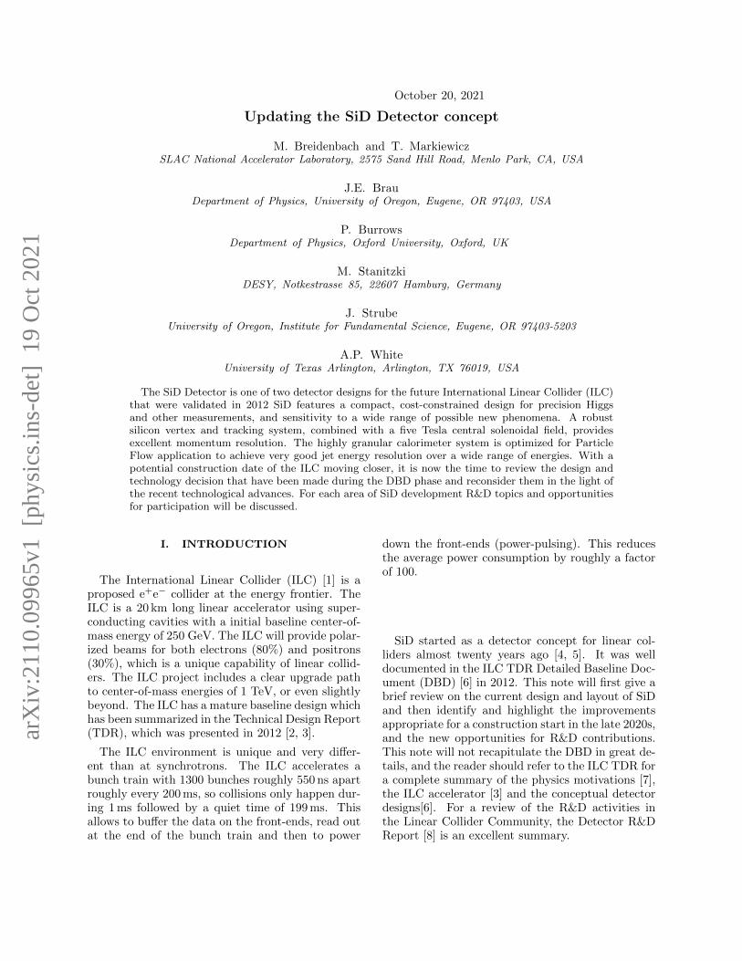
The SiD detector has been designed as a general-purpose experiment designed to perform precisionmeasurements at the ILC. It satisfies the challengingdetector requirements resulting from the full rangeof ILC physics processes and range of COM ener-gies. SiD is based on the paradigm of particle flow,an algorithm by which the reconstruction of bothcharged and neutral particles is accomplished byan optimized combination of tracking and calorime-try. The net result is a significantly more precisejet energy measurement which results in a di-jetmass resolution good enough to distinguish betweenhadronically decaying W s and Zs. The SiD detector(Fig. 1) is a compact detector based on a powerfulsilicon pixel vertex detector, silicon tracking, silicon-tungsten electromagnetic calorimetry, and highlysegmented hadronic calorimetry. SiD also incorpo-rates a high-field solenoid, iron flux return, a muonidentification system, and forward calorimetry. Theuse of silicon sensors in the vertex, tracking, andcalorimetry enables a unique integrated tracking sys-tem ideally suited to particle flow.
The choice of silicon detectors for tracking andvertexing ensures that SiD is robust with respectto beam backgrounds or beam loss, provides su-perior charged particle momentum resolution, andeliminates out-of-time tracks and backgrounds. Themain tracking detector and calorimeters can time-stamp each individual bunch crossing, so beam-related backgrounds and low-pT background eventsoriginating from γγ processes will be reduced to theminimum possible levels. The SiD calorimetry is op-timized for excellent jet energy measurement usingthe particle flow technique. The complete track-ing and calorimeter systems are contained withina superconducting solenoid, which has a 5 T fieldstrength, enabling the overall compact design. Thecoil is located within a layered iron structure thatreturns the magnetic flux and is instrumented to al-low the identification of muons. All aspects of SiDare the result of intensive and leading-edge researchaimed at achieving performance at unprecedentedlevels. At the same time, the design represents abalance between cost and physics performance. Thekey parameters of the SiD design are listed in Ta-ble I.
FIG. 1: The SiD detector concept as presented inthe DBD.
SiD Barrel Technology In rad Out rad z extent
Vtx detector Silicon pixels 1.4 6.0 ± 6.25
Tracker Silicon strips 21.7 122.1 ± 152.2
ECAL Silicon pixels-W 126.5 140.9 ± 176.5
HCAL RPC-steel 141.7 249.3 ± 301.8
Solenoid 5 Tesla SC 259.1 339.2 ± 298.3
Flux return Scint-steel 340.2 604.2 ± 303.3
SiD Endcap Technology In z Out z Out rad
Vtx detector Silicon pixels 7.3 83.4 16.6
Tracker Silicon strips 77.0 164.3 125.5
ECAL Silicon pixel-W 165.7 180.0 125.0
HCAL RPC-steel 180.5 302.8 140.2
Flux return Scint/steel 303.3 567.3 604.2
LumiCal Silicon-W 155.7 170.0 20.0
BeamCal Semicond-W 277.5 300.7 13.5
TABLE I: Key parameters of the baseline SiDdesign. (All dimension are given in cm).
III. CHANGES TO THE BASELINEPOST-DBD
With the completion of the DBD and the intentionfrom the Japanese HEP community to host the ILCin Japan, two major design changes were made tothe baseline designs, that was presented in the DBD,the switch from a purely digital hadron calorime-ter (DHCAL) with RPCs as active medium [9–12]to a scintillator-based solution with analog read-out(AHCAL)and the change of the iron yoke from a oc-tagon to a dodecagon. The first choice was driven bythe huge progress in the SiPM technology in terms ofnoise and stability, while at the same time the limi-
2
4 m
2 m
1 m
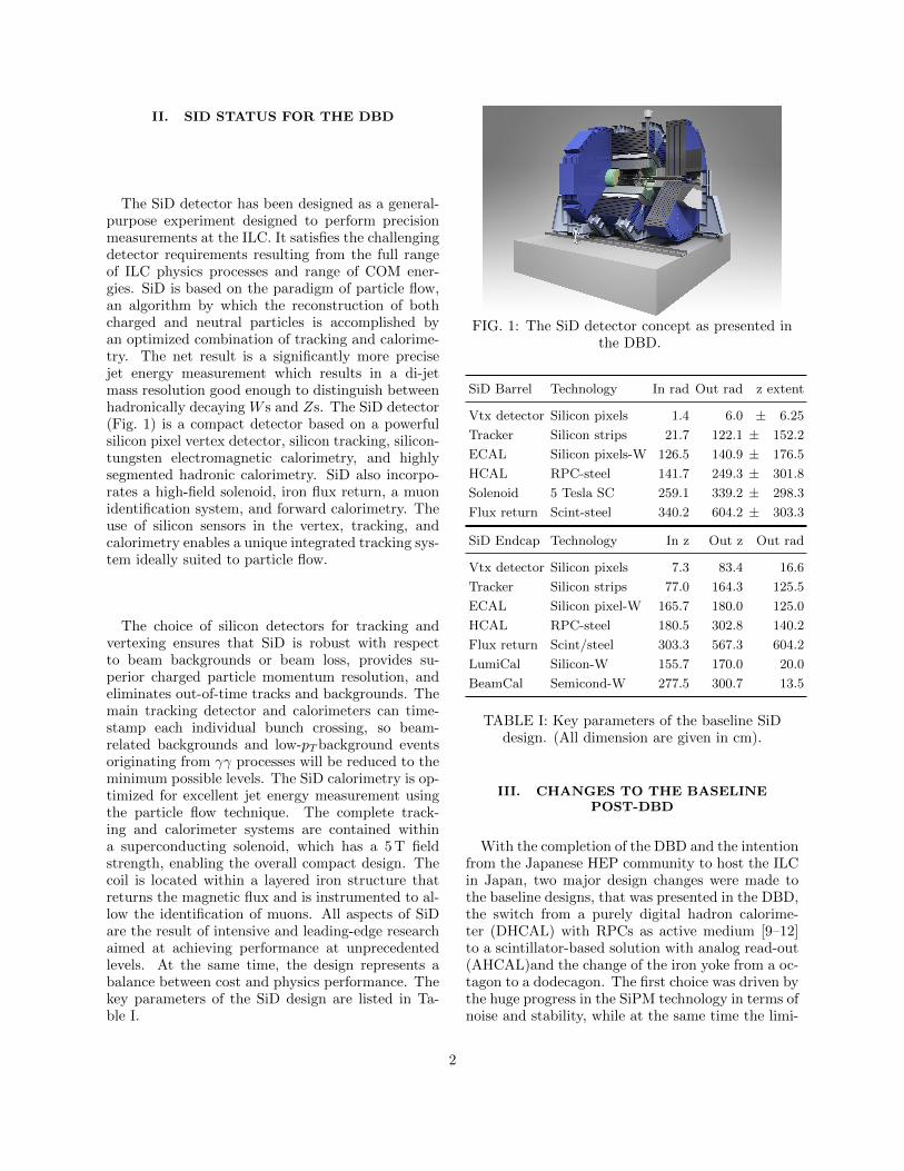
FIG. 2: The SiD detector concept with thereconfigured dodecagonal iron yoke.
tations of a large-scale RPC system with several mil-lion individual channels in terms of uniformity, cal-ibration and long-term stability became more clear.As there were neither clear cost or performance ben-efits of the DHCAL at the time, this led to a switchto an AHCAL solution. The mechanical structureof the HCAL was left unchanged.
From a systems point of view, the eliminationof both a 7 kV HV system and an elaborated gassystem had of course significant implications, as noother other sub-detector of SiD required such sys-tems.
The second choice was mainly driven by site-specific studies for the potential Kitakami site. TheSiD iron yoke is assembled by stacking of eleven in-dividual iron plates into wedges. By switching theiron-yoke geometry from an octagon to a dodecagon,the weight of the individual plates could be keptbelow 30 t, allowing easier transport by truck onJapanese highways. At the same time the overallyoke design changed from a vertical interface be-tween the barrel and endcap to a thirty degree in-terface.
IV. UPDATING THE SID DETECTORDESIGN
The last time the SiD detector design received amajor overhaul was in the preparation of the DBD.With almost a decade past, technology choices, inparticular, for the individual subsystems need to bereviewed. In the follow section, potential updatesare outlined showcasing also the areas where dedi-cated R&D is needed and new contribution wouldbe extremely welcome. Also with the advances intechnology driven e.g. by the HL-LHC in terms ofsilicon sensor and ASIC development, novel timing
detectors and improved services for power distribu-tion and data transmission, it would be very inter-esting to explore how these could be incorporatedinto an updated SiD detector concept.
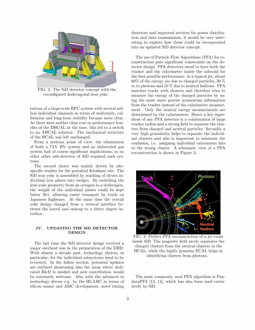
The use of Particle Flow Algorithms (PFA) for re-construction puts significant constraints on the de-tector design. PFA detectors meed to have both thetracker and the calorimeter inside the solenoid forthe best possible performance. in a typical jet, about60% of the energy are due to charged particles, 30 %to to photons and 10 % due to neutral hadrons. PFAmatches tracks with showers and therefore tries tomeasure the energy of the charged particles by us-ing the most more precise momentum informationfrom the tracker instead of the calorimeter measure-ment. Only the neutral energy measurements aredetermined by the calorimeters. Hence a key ingre-dient of any PFA detector is a combination of largetracker radius and a strong field to separate the clus-ters from charged and neutral particles. Secondly avery high granularity helps to separate the individ-ual clusters and also is important to minimize theconfusion, i.e. assigning individual calorimeter hitsto the wrong cluster. A schematic view of a PFAreconstruction is shown in Figure 3.
FIG. 3: Perfect PFA reconstruction of a jet eventinside SiD. The magnetic field nicely separates thecharged clusters from the neutral clusters in theHCAL, while the highly granular ECAL helps in
identifying clusters from photons.
The most commonly used PFA algorithm is Pan-doraPFA [13, 14], which has also been used exten-sively by SiD.
3
A. Overall detector geometry
The overall detector geometry has been quite sta-ble, but there have been a few areas of discussionover the last year, which need to be revisited on theroad toward a TDR for SiD. Particularly the trackergeometry and the calorimeter thickness have a hugeimpact on both physics performance and cost. In thefollowing a few points to be revisited and optimizedare described in more detail.
1. Tracker radius and aspect ratio
The outer radius of the tracker was fixed at 1.25 m,mainly driven by the need to fit both tracker andcalorimeter inside the solenoid and the maximumradius of a solenoid with a 5 T field. Having a largerradius would help in the shower separation, which isbeneficial for the PFA reconstruction. However, thecurrent layout is already quite close to the maxi-mum coil radius, so the impact of a modest increaseof the radius needs to be studied. It was alreadyconcluded for the DBD, that a going significantlybelow 1.25 m radius, severely impacts the PFA per-formance [15]. For the DBD the tracker length wasfixed to 331.4 cm, as the tracker mechanica l sup-port structure at the time would not allow a signif-icant extension in length. Simulation studies haveshown [15], that moving the transition between bar-rel and end-cap further out in z could be beneficialfor the overall performance of SiD.
2. Thickness of the calorimeter system
The SiD calorimeter thickness (20+10 layers inthe ECAL, 40 layers in the HCAL) was optimized toprovide an excellent jet resolution from
√s =91 GeV
to 1 TeV. However the number of layers and totalthickness of the system could be re-optimized, as thecalorimeter system is a major cost driver. Studiesfor the ECAL as the major cost-driver have alreadyshown, that for pure electromagnetic energy perfor-mance a thinner calorimeter would be sufficient [16].
B. Monolithic Active Pixel Sensors
The SiD silicon baseline as described in the DBDbased on two large area high-resistivity silicon diodearrays for both the main tracker and the ECALthat are read out with the bump bonded KPiX.
The possibility of stitching reticules together withdeep implants [17] and depletion of the epitaxiallayer make Monolithic Active Pixel sensors (MAPS)is extremely attractive. SiD has currently focusedits efforts on the Tower-Jazz 65 nm process. Thefundamental specifications are sensors of at least10× 10 cm2 with pixels of 20× 20 µm2. The sameMAPS sensor could be used for the tracker and theECAL. The sensor is readout by digital electronicson a ”balcony” 0.5 mm high on one edge of the sen-sor. Each pixel should have at least simple discrim-inator (one bit) and needs to records the time forbunch identification. Distribution of power over sucha large area is challenging. The working assumptionis that flat cables will both handle control and data,as well as power distribution to the reticules.
C. Vertex Detector
Since the DBD, SiD uses a vertex detector de-sign with five individual layers in the barrel and fourdisks in the endcaps. Taking advantage of the large5 T field, the inner radius of the Vertex Detector ismerely 1.4 cm away from the interaction point. Thislayout has been shown to give an excellent perfor-mance, however a further refinement of the layoutis needed. The resolution requirements for the SiDVertex Detector have remained unchanged since theDBD, a point resolution of better than 3 µm, whichmandates either pixels with a pure binary readoutwith a pixel pitch of 10 µm, or a analog readoutwith a pixel pitch of 15-20 µm. While there havebeen many promising developments already [18–21],a MAPS which is meeting all the SiD requirementsis not yet available. The ongoing developments onthe Tower-Jazz 65 nm process are currently the mostpromising ones and the ALICE ITS3 upgrade willbe the first major user of this technology. Giventhe currently foreseen assembly scheme, the VertexDetector would be installed last and technology de-cisions can be taken much later than for other sub-systems, taking full advantage of the latest develop-ments in CMOS technology.
The beam background levels at the several pro-posed ILC operating energies are quite different [22],so the Vertex Detector is foreseen to be upgradablein a shutdown, which also opens the possibility todesign an optimal Vertex Detector for each center-of-mass energy.
The impact of the layout and resolution as well asits material budget of the Vertex Detector on the fla-vor tagging performance need to be revisited. Thesestudies will then also guide the design of a dedicated
4
MAPS for the Vertex Detector.
D. Tracker
The Tracker design described in the DBD is basedon high-resistivity Silicon-strip sensors with a size of10 × 10 cm and a strip-pitch of 25 µm readout by aSystem on Chip (SOC) KPiX [23], bump bonded tothe Silicon sensor. The sensor using a second metallayer to connect the individual strips to KPiX, andno hybrid is required. A fully functional prototypehas recently been assembled tested [24] and achievedthe desired resolution of 7 µm. The overall trackerlayout uses five nested cylinders in the barrel regionand four disks following a conical surface with anangle of 5 degrees with respect to the normal to thebeamline in each of the endcaps. In the endcaps, thedisks use two sensors mounted back to back to allowa small-angle stereo configuration.
A MAPS-based tracker for SiD would be basedon a similar size of the sensor, as described above.The sensors would be aligned with the 25 micronpixel dimension in the bend direction, and wouldhave a resolution of 25/root(12) as charge sharingis not assumed. For the endcaps, such a sensorwould eliminate the need for two sensors in a small-angle-stereo configuration, reducing both the mate-rial budget and cost.
E. Common Tracking aspects
For SiD, the vertex detector and main tracker havealways been treated as an integrated system. Forthe overall system the question remains if the cur-rent configuration could be improved and while thetracking resilience against backgrounds has been ex-tensively tested, a detailed study of the robustnessof the tracker towards failures of individual chan-nels or complete sensors would be further input tothe overall layout. Alignment of the tracking systemwill remain a challenge, as the level of e.g. Z→ µ+µ−
events will be too small for beam-based alignment.Integrated scanning interferometers are expected tohave adequate precision.
With the advent of fast timing and 4D-tracking,the impact on the performance of the SiD trackingsystem needs to be demonstrated.
Future studies for the tracking system include
• Optimal Pixel size for the Vertex Detector andthe tracker
• Mechanical support structures, cooling andstability
• Alignment studies
F. Electromagnetic Calorimeter
The ECAL is a sampling calorimeter using W asa radiator with ≈ 1 mm gaps for the Silicon sensors.The current design uses high resistivity sensors cutinto hexagons that are as large as practical from asix inch wafer. Similarly to the Tracker, a KPiXASIC is bump-bonded to each sensor. This concepthas been successfully demonstrated in several beamtests [25] Given the huge technical progress made forMAPS, a study has started to consider large- areaMAPS for the ECAL, eliminating the need for thedelicate and expensive bump-bonding, while signif-icantly improving the shower separation within thecalorimeter.
As discussed before, a pixel area of 2500 µm2
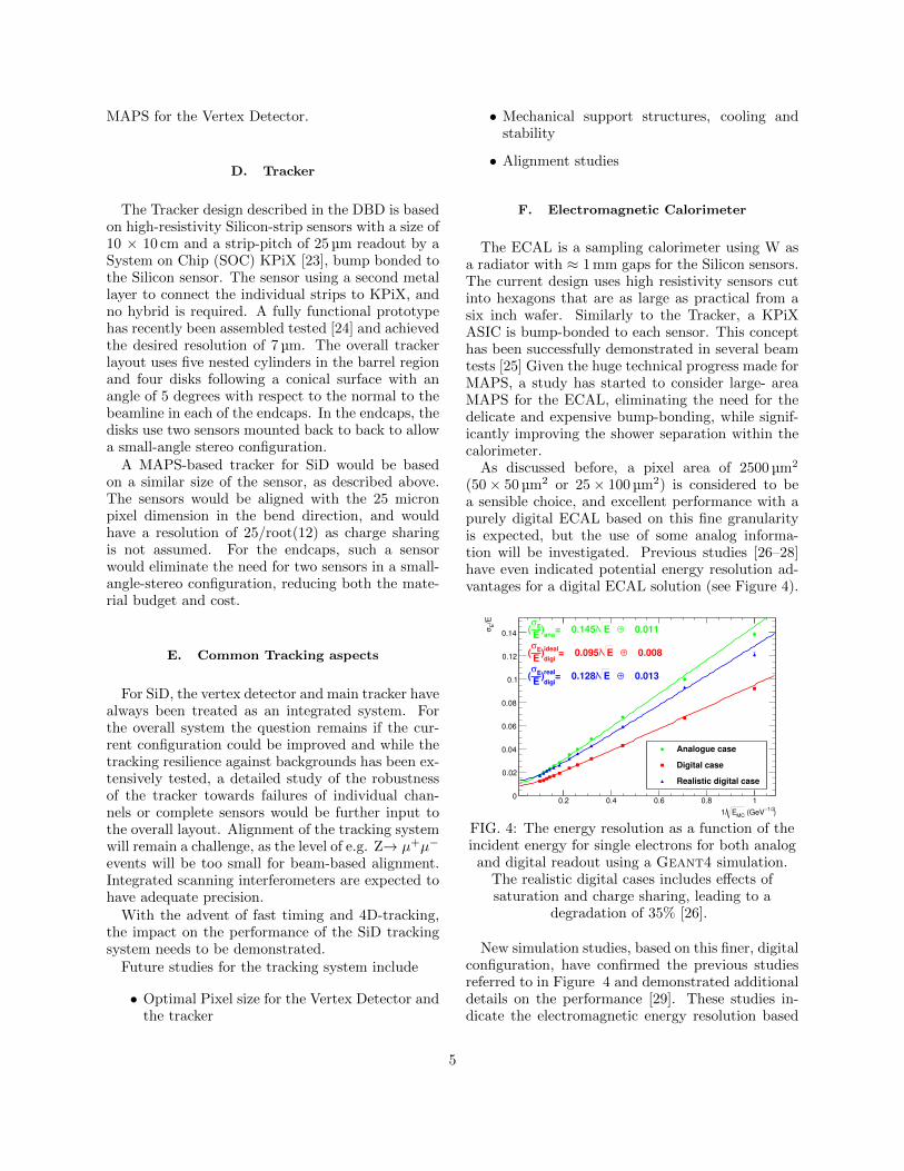
(50× 50 µm2 or 25× 100 µm2) is considered to bea sensible choice, and excellent performance with apurely digital ECAL based on this fine granularityis expected, but the use of some analog informa-tion will be investigated. Previous studies [26–28]have even indicated potential energy resolution ad-vantages for a digital ECAL solution (see Figure 4).
)−1/2
(GeVMC
E1/
0.2 0.4 0.6 0.8 1
/EE
σ
0
0.02
0.04
0.06
0.08
0.1
0.12
0.14
Analogue case
Digital case
Realistic digital case
0.011⊕ E= 0.145/ana
)E
Eσ
(
0.008⊕ E= 0.095/ideal
digi)
EE
σ(
0.013⊕ E= 0.128/real
digi)
EE
σ(
FIG. 4: The energy resolution as a function of theincident energy for single electrons for both analog
and digital readout using a Geant4 simulation.The realistic digital cases includes effects ofsaturation and charge sharing, leading to a
degradation of 35% [26].
New simulation studies, based on this finer, digitalconfiguration, have confirmed the previous studiesreferred to in Figure 4 and demonstrated additionaldetails on the performance [29]. These studies in-dicate the electromagnetic energy resolution based
5
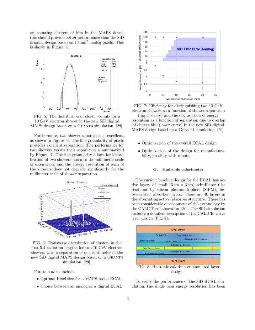
on counting clusters of hits in the MAPS detec-tors should provide better performance than the SiDoriginal design based on 13 mm2 analog pixels. Thisis shown in Figure 5.
FIG. 5: The distribution of cluster counts for a10 GeV electron shower in the new SiD digital
MAPS design based on a Geant4 simulation. [29]
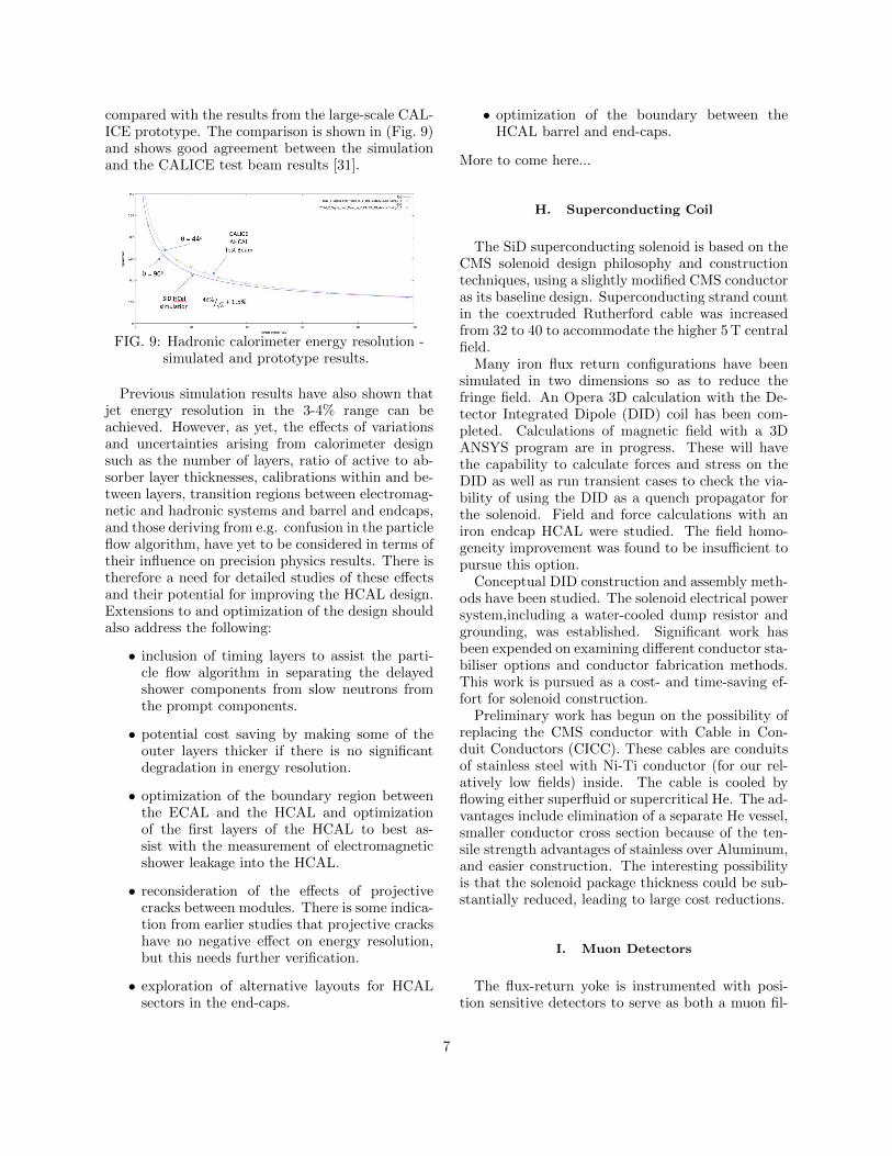
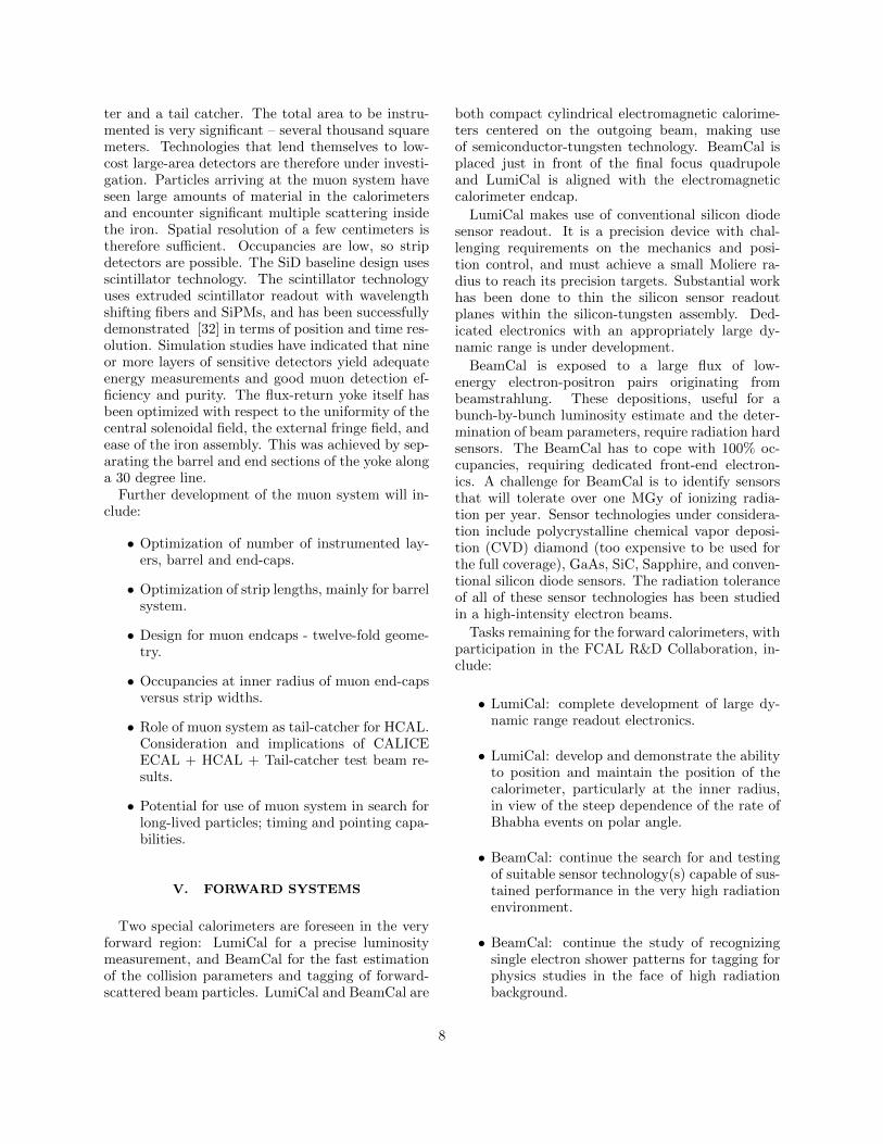
Furthermore, two shower separation is excellent,as shown in Figure 6. The fine granularity of pixelsprovides excellent separation. The performance fortwo showers versus their separation is summarizedby Figure 7. The fine granularity allows for identi-fication of two showers down to the millimeter scaleof separation, and the energy resolution of each ofthe showers does not degrade significantly for themillimeter scale of shower separation.
FIG. 6: Transverse distribution of clusters in thefirst 5.4 radiation lengths for two 10 GeV electronshowers with a separation of one centimeter in thenew SiD digital MAPS design based on a Geant4
simulation. [29]
Future studies include:
• Optimal Pixel size for a MAPS-based ECAL
• Choice between an analog or a digital ECAL
FIG. 7: Efficiency for distinguishing two 10 GeVelectron showers as a function of shower separation
(upper curve) and the degradation of energyresolution as a function of separation due to overlapof cluster hits (lower curve) in the new SiD digitalMAPS design based on a Geant4 simulation. [29]
• Optimization of the overall ECAL design
• Optimization of the design for manufactura-bilty, possibly with robots.
G. Hadronic calorimeter
The current baseline design for the HCAL has ac-tive layers of small (3 cm × 3 cm) scintillator tilesread out by silicon photomultipliers (SiPM), be-tween steel absorber layers. There are 40 layers inthe alternating active/absorber structure. There hasbeen considerable development of this technology bythe CALICE collaboration [30]. The SiD simulationincludes a detailed description of the CALICE activelayer design (Fig. 8).
FIG. 8: Hadronic calorimeter simulated layerdesign.
To verify the performance of the SiD HCAL sim-ulation, the single pion energy resolution has been
6
compared with the results from the large-scale CAL-ICE prototype. The comparison is shown in (Fig. 9)and shows good agreement between the simulationand the CALICE test beam results [31].
FIG. 9: Hadronic calorimeter energy resolution -simulated and prototype results.
Previous simulation results have also shown thatjet energy resolution in the 3-4% range can beachieved. However, as yet, the effects of variationsand uncertainties arising from calorimeter designsuch as the number of layers, ratio of active to ab-sorber layer thicknesses, calibrations within and be-tween layers, transition regions between electromag-netic and hadronic systems and barrel and endcaps,and those deriving from e.g. confusion in the particleflow algorithm, have yet to be considered in terms oftheir influence on precision physics results. There istherefore a need for detailed studies of these effectsand their potential for improving the HCAL design.Extensions to and optimization of the design shouldalso address the following:
• inclusion of timing layers to assist the parti-cle flow algorithm in separating the delayedshower components from slow neutrons fromthe prompt components.
• potential cost saving by making some of theouter layers thicker if there is no significantdegradation in energy resolution.
• optimization of the boundary region betweenthe ECAL and the HCAL and optimizationof the first layers of the HCAL to best as-sist with the measurement of electromagneticshower leakage into the HCAL.
• reconsideration of the effects of projectivecracks between modules. There is some indica-tion from earlier studies that projective crackshave no negative effect on energy resolution,but this needs further verification.
• exploration of alternative layouts for HCALsectors in the end-caps.
• optimization of the boundary between theHCAL barrel and end-caps.
More to come here...
H. Superconducting Coil
The SiD superconducting solenoid is based on theCMS solenoid design philosophy and constructiontechniques, using a slightly modified CMS conductoras its baseline design. Superconducting strand countin the coextruded Rutherford cable was increasedfrom 32 to 40 to accommodate the higher 5 T centralfield.
Many iron flux return configurations have beensimulated in two dimensions so as to reduce thefringe field. An Opera 3D calculation with the De-tector Integrated Dipole (DID) coil has been com-pleted. Calculations of magnetic field with a 3DANSYS program are in progress. These will havethe capability to calculate forces and stress on theDID as well as run transient cases to check the via-bility of using the DID as a quench propagator forthe solenoid. Field and force calculations with aniron endcap HCAL were studied. The field homo-geneity improvement was found to be insufficient topursue this option.
Conceptual DID construction and assembly meth-ods have been studied. The solenoid electrical powersystem,including a water-cooled dump resistor andgrounding, was established. Significant work hasbeen expended on examining different conductor sta-biliser options and conductor fabrication methods.This work is pursued as a cost- and time-saving ef-fort for solenoid construction.
Preliminary work has begun on the possibility ofreplacing the CMS conductor with Cable in Con-duit Conductors (CICC). These cables are conduitsof stainless steel with Ni-Ti conductor (for our rel-atively low fields) inside. The cable is cooled byflowing either superfluid or supercritical He. The ad-vantages include elimination of a separate He vessel,smaller conductor cross section because of the ten-sile strength advantages of stainless over Aluminum,and easier construction. The interesting possibilityis that the solenoid package thickness could be sub-stantially reduced, leading to large cost reductions.
I. Muon Detectors
The flux-return yoke is instrumented with posi-tion sensitive detectors to serve as both a muon fil-
7
ter and a tail catcher. The total area to be instru-mented is very significant – several thousand squaremeters. Technologies that lend themselves to low-cost large-area detectors are therefore under investi-gation. Particles arriving at the muon system haveseen large amounts of material in the calorimetersand encounter significant multiple scattering insidethe iron. Spatial resolution of a few centimeters istherefore sufficient. Occupancies are low, so stripdetectors are possible. The SiD baseline design usesscintillator technology. The scintillator technologyuses extruded scintillator readout with wavelengthshifting fibers and SiPMs, and has been successfullydemonstrated [32] in terms of position and time res-olution. Simulation studies have indicated that nineor more layers of sensitive detectors yield adequateenergy measurements and good muon detection ef-ficiency and purity. The flux-return yoke itself hasbeen optimized with respect to the uniformity of thecentral solenoidal field, the external fringe field, andease of the iron assembly. This was achieved by sep-arating the barrel and end sections of the yoke alonga 30 degree line.
Further development of the muon system will in-clude:
• Optimization of number of instrumented lay-ers, barrel and end-caps.
• Optimization of strip lengths, mainly for barrelsystem.
• Design for muon endcaps - twelve-fold geome-try.
• Occupancies at inner radius of muon end-capsversus strip widths.
• Role of muon system as tail-catcher for HCAL.Consideration and implications of CALICEECAL + HCAL + Tail-catcher test beam re-sults.
• Potential for use of muon system in search forlong-lived particles; timing and pointing capa-bilities.
V. FORWARD SYSTEMS
Two special calorimeters are foreseen in the veryforward region: LumiCal for a precise luminositymeasurement, and BeamCal for the fast estimationof the collision parameters and tagging of forward-scattered beam particles. LumiCal and BeamCal are
both compact cylindrical electromagnetic calorime-ters centered on the outgoing beam, making useof semiconductor-tungsten technology. BeamCal isplaced just in front of the final focus quadrupoleand LumiCal is aligned with the electromagneticcalorimeter endcap.
LumiCal makes use of conventional silicon diodesensor readout. It is a precision device with chal-lenging requirements on the mechanics and posi-tion control, and must achieve a small Moliere ra-dius to reach its precision targets. Substantial workhas been done to thin the silicon sensor readoutplanes within the silicon-tungsten assembly. Ded-icated electronics with an appropriately large dy-namic range is under development.
BeamCal is exposed to a large flux of low-energy electron-positron pairs originating frombeamstrahlung. These depositions, useful for abunch-by-bunch luminosity estimate and the deter-mination of beam parameters, require radiation hardsensors. The BeamCal has to cope with 100% oc-cupancies, requiring dedicated front-end electron-ics. A challenge for BeamCal is to identify sensorsthat will tolerate over one MGy of ionizing radia-tion per year. Sensor technologies under considera-tion include polycrystalline chemical vapor deposi-tion (CVD) diamond (too expensive to be used forthe full coverage), GaAs, SiC, Sapphire, and conven-tional silicon diode sensors. The radiation toleranceof all of these sensor technologies has been studiedin a high-intensity electron beams.
Tasks remaining for the forward calorimeters, withparticipation in the FCAL R&D Collaboration, in-clude:
• LumiCal: complete development of large dy-namic range readout electronics.
• LumiCal: develop and demonstrate the abilityto position and maintain the position of thecalorimeter, particularly at the inner radius,in view of the steep dependence of the rate ofBhabha events on polar angle.
• BeamCal: continue the search for and testingof suitable sensor technology(s) capable of sus-tained performance in the very high radiationenvironment.
• BeamCal: continue the study of recognizingsingle electron shower patterns for tagging forphysics studies in the face of high radiationbackground.
8
VI. ELECTRONICS & DAQ
The Electronics and DAQ needs are strongly tiedto the ILC environment, with short bunch trains(1 ms) followed by a long quiet time (199 ms), en-abling front-end buffering and read-out during thequiet time and with power-pulsing the front-ends toreduce the overall power consumption. At the sametime the physics event rate is a lot smaller than ate.g. the LHC and the main occupancy drivers arethe beam backgrounds and the detector noise.
A. Front-end electronics
With the incorporation of more and more MAPS-based subdetectors, the front-end ASICs become lessand less widespread, and most likely the HCAL willbe the first detector using classical front-end forreading out the SiPMs. At the same time, the roleof data concentration will only increase, bundlingthe data streams from several MAPS units intohigh-speed data links and moving them off-detector.More development is needed for DC-DC convertersthat are in the magnetic field and deal elegantly withthe pulsed front end load.
B. DAQ
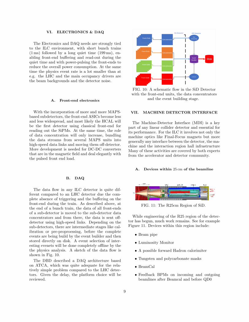
The data flow in any ILC detector is quite dif-ferent compared to an LHC detector due the com-plete absence of triggering and the buffering on thefront-end during the train. As described above, atthe end of a bunch train, the data of all front-endsof a sub-detector is moved to the sub-detector dataconcentrators and from there, the data is sent off-detector using high-speed links. Depending on thesub-detectors, there are intermediate stages like cal-ibration or pre-proproessing, before the completeevents are being build by the event builder and thenstored directly on disk. A event selection of inter-esting evenets will be done completely offline by thethe physics analysis. A sketch of the data flow isshown in Fig. 10.
The DBD described a DAQ architecture basedon ATCA, which was quite adequate for the rela-tively simple problem compared to the LHC detec-tors. Given the delay, the platform choice will bereviewed.
Front-EndsFront-Ends
Front-EndsFront-Ends
Front-EndsFront-Ends
Front-EndsFront-Ends
Front-EndsFront-Ends
Front-EndsFront-Ends
Front-EndsFront-Ends
Front-EndsFront-Ends
Concatenator
Concatenator
Concatenator
Concatenator
Event Builder
On-Detector Off-Detector
Pre-processing
Calibration
Disk
FIG. 10: A schematic flow in the SiD Detectorwith the front-end units, the data concentrators
and the event building stage.
VII. MACHINE DETECTOR INTERFACE
The Machine-Detector Interface (MDI) is a keypart of any linear collider detector and essential forits performance. For the ILC it involves not only themachine optics like Final-Focus magnets but moregenerally any interface between the detector, the ma-chine and the interaction region hall infrastructureMany of these activities are covered by both expertsfrom the accelerator and detector community.
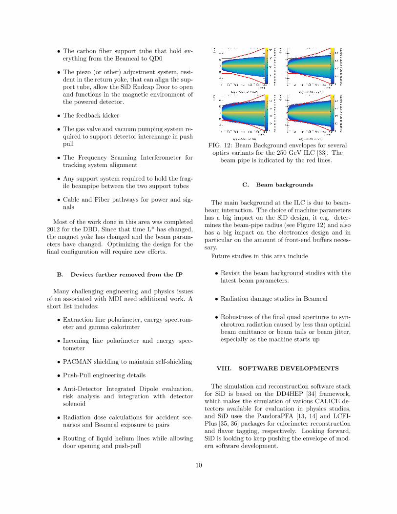
A. Devices within 25 cm of the beamline
FIG. 11: The R25cm Region of SiD.
While engineering of the R25 region of the detec-tor has begun, much work remains. See for exampleFigure 11. Devices within this region include:
• Beam pipe
• Luminosity Monitor
• A possible forward Hadron calorimiter
• Tungsten and polycarbonate masks
• BeamCal
• Feedback BPMs on incoming and outgoingbeamlines after Beamcal and before QD0
9
• The carbon fiber support tube that hold ev-erything from the Beamcal to QD0
• The piezo (or other) adjustment system, resi-dent in the return yoke, that can align the sup-port tube, allow the SiD Endcap Door to openand functions in the magnetic environment ofthe powered detector.
• The feedback kicker
• The gas valve and vacuum pumping system re-quired to support detector interchange in pushpull
• The Frequency Scanning Interferometer fortracking system alignment
• Any support system required to hold the frag-ile beampipe between the two support tubes
• Cable and Fiber pathways for power and sig-nals
Most of the work done in this area was completed2012 for the DBD. Since that time L* has changed,the magnet yoke has changed and the beam param-eters have changed. Optimizing the design for thefinal configuration will require new efforts.
B. Devices further removed from the IP
Many challenging engineering and physics issuesoften associated with MDI need additional work. Ashort list includes:
• Extraction line polarimeter, energy spectrom-eter and gamma calorimter
• Incoming line polarimeter and energy spec-tometer
• PACMAN shielding to maintain self-shielding
• Push-Pull engineering details
• Anti-Detector Integrated Dipole evaluation,risk analysis and integration with detectorsolenoid
• Radiation dose calculations for accident sce-narios and Beamcal exposure to pairs
• Routing of liquid helium lines while allowingdoor opening and push-pull
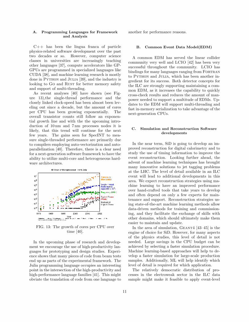
FIG. 12: Beam Background envelopes for severaloptics variants for the 250 GeV ILC [33]. The
beam pipe is indicated by the red lines.
C. Beam backgrounds
The main background at the ILC is due to beam-beam interaction. The choice of machine parametershas a big impact on the SiD design, it e.g. deter-mines the beam-pipe radius (see Figure 12) and alsohas a big impact on the electronics design and inparticular on the amount of front-end buffers neces-sary.
Future studies in this area include
• Revisit the beam background studies with thelatest beam parameters.
• Radiation damage studies in Beamcal
• Robustness of the final quad apertures to syn-chrotron radiation caused by less than optimalbeam emittance or beam tails or beam jitter,especially as the machine starts up
VIII. SOFTWARE DEVELOPMENTS
The simulation and reconstruction software stackfor SiD is based on the DD4HEP [34] framework,which makes the simulation of various CALICE de-tectors available for evaluation in physics studies,and SiD uses the PandoraPFA [13, 14] and LCFI-Plus [35, 36] packages for calorimeter reconstructionand flavor tagging, respectively. Looking forward,SiD is looking to keep pushing the envelope of mod-ern software development.
10
A. Programming Languages for Frameworkand Analysis
C++ has been the lingua franca of particlephysics-related software development over the pasttwo decades or so. However, computer scienceclasses in universities are increasingly teachingother languages [37], compute accelerators like GP-GPUs are programmed in specialized languages likeCUDA [38], and machine learning research is mostlydone in Python and Julia [39], and the industry islooking to Go and Rust for better memory safetyand support of multi-threading.
As recent analyses [40] have shown (see Fig-ure 13),the single-thread performance and theclosely linked clock-speed has been almost been lev-eling out since a decade, but the amount of coresper CPU has been growing exponentially. Theoverall transistor counts still follow an exponen-tial growth line and with the the upcoming intro-duction of 10 nm and 7 nm processes nodes it islikely, that this trend will continue for the nextfew years. The gains seen for SpecINT to mea-sure single-threaded performance are primarily dueto compilers employing auto-vectorization and auto-parallelization [40]. Therefore, there is a clear needfor a next-generation software framework to have theability to utilize multi-core and heterogeneous hard-ware architectures.
FIG. 13: The growth of cores per CPU overtime [40].
In the upcoming phase of research and develop-ment we encourage the use of high-productivity lan-guages for prototyping and design studies. Experi-ence shows that many pieces of code from beam testsend up as parts of the experimental framework. TheJulia programming language occupies an interestingpoint in the intersection of the high-productivity andhigh-performance language families [41]. This mightobviate the translation of code from one language to
another for performance reasons.
B. Common Event Data Model(EDM)
A common EDM has served the linear collidercommunity very well and LCIO [42] has been verysuccessful throughout the community. LCIO hasbindings for many languages ranging from Fortranto Python and Julia, which has been another in-gredient for its success. Both detector concepts forthe ILC are strongly supporting maintaining a com-mon EDM, as it increases the capability to quicklycross-check results and reduces the amount of man-power needed to support a multitude of EDMs. Up-dates to the EDM will support multi-threading andfast in-memory serialization to take advantage of thenext-generation CPUs.
C. Simulation and Reconstruction Softwaredevelopments
In the near term, SiD is going to develop an im-proved reconstruction for digital calorimetry and tostudy the use of timing information to improve theevent reconstruction. Looking further ahead, theadvent of machine learning techniques has broughtmany innovative solutions to jet tagging problemsat the LHC. The level of detail available in an ILCevent will lead to additional developments in thisarea. We expect reconstruction strategies using ma-chine learning to have an improved performanceover hand-crafted tools that take years to developand often depend on only a few experts for main-tenance and support. Reconstruction strategies us-ing state-of-the-art machine learning methods allowdata-driven methods for training and commission-ing, and they facilitate the exchange of skills withother domains, which should ultimately make themeasier to maintain and update.
In the area of simulation, Geant4 [43–45] is theengine of choice for SiD. However, for many aspectsof the physics studies, this level of detail is notneeded. Large savings in the CPU budget can beachieved by selecting a faster simulation procedure.Machine learning-based approaches will help to de-velop a faster simulation for large-scale productionsamples. Additionally, ML will help identify whichlevel of detail is required for which application.
The relatively democratic distribution of pro-cesses in the electroweak sector in the ILC datasample might make it feasible to apply event-level
11
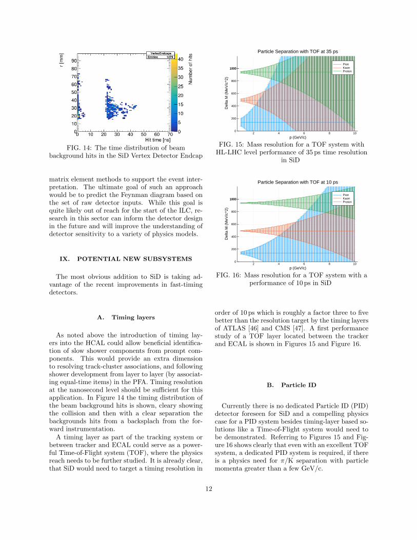
FIG. 14: The time distribution of beambackground hits in the SiD Vertex Detector Endcap
matrix element methods to support the event inter-pretation. The ultimate goal of such an approachwould be to predict the Feynman diagram based onthe set of raw detector inputs. While this goal isquite likely out of reach for the start of the ILC, re-search in this sector can inform the detector designin the future and will improve the understanding ofdetector sensitivity to a variety of physics models.
IX. POTENTIAL NEW SUBSYSTEMS
The most obvious addition to SiD is taking ad-vantage of the recent improvements in fast-timingdetectors.
A. Timing layers
As noted above the introduction of timing lay-ers into the HCAL could allow beneficial identifica-tion of slow shower components from prompt com-ponents. This would provide an extra dimensionto resolving track-cluster associations, and followingshower development from layer to layer (by associat-ing equal-time items) in the PFA. Timing resolutionat the nanosecond level should be sufficient for thisapplication. In Figure 14 the timing distribution ofthe beam background hits is shown, cleary showingthe collision and then with a clear separation thebackgrounds hits from a backsplach from the for-ward instrumentation.
A timing layer as part of the tracking system orbetween tracker and ECAL could serve as a power-ful Time-of-Flight system (TOF), where the physicsreach needs to be further studied. It is already clear,that SiD would need to target a timing resolution in
2 4 6 8 100
200
400
600
800
10001000
Particle Separation with TOF at 35 ps
p (GeV/c)
Del
ta M
(M
eV/c
^2)
PionKaonProton
FIG. 15: Mass resolution for a TOF system withHL-LHC level performance of 35 ps time resolution
in SiD
2 4 6 8 100
200
400
600
800
10001000
Particle Separation with TOF at 10 ps
p (GeV/c)
Del
ta M
(M
eV/c
^2)
PionKaonProton
FIG. 16: Mass resolution for a TOF system with aperformance of 10 ps in SiD
order of 10 ps which is roughly a factor three to fivebetter than the resolution target by the timing layersof ATLAS [46] and CMS [47]. A first performancestudy of a TOF layer located between the trackerand ECAL is shown in Figures 15 and Figure 16.
B. Particle ID
Currently there is no dedicated Particle ID (PID)detector foreseen for SiD and a compelling physicscase for a PID system besides timing-layer based so-lutions like a Time-of-Flight system would need tobe demonstrated. Referring to Figures 15 and Fig-ure 16 shows clearly that even with an excellent TOFsystem, a dedicated PID system is required, if thereis a physics need for π/K separation with particlemomenta greater than a few GeV/c.
12
X. CONCLUSION
SiD was originally conceived in the middle of thefirst decade of this century and technology has sincethen made major steps forward. With the realiza-tion of the ILC becoming now a real possibility, it istimely to revisit the technology choices and update
them accordingly. The replacement of the siliconstrips and pad systems in the tracker and ECALwith MAPS is an obvious decision given recent ad-vances. For the HCAL the move to a SiPM-basedreadout has already been made, opening up also syn-ergies with the SiD muon system.
[1] T. Behnke, J. E. Brau, B. Foster, J. Fuster, M. Har-rison, J. M. Paterson, M. Peskin, M. Stanitzki,N. Walker, and H. Yamamoto, The InternationalLinear Collider Technical Design Report - Volume1: Executive Summary, (2013), arXiv:1306.6327[physics.acc-ph].
[2] C. Adolphsen et al., The International Linear Col-lider Technical Design Report - Volume 3.I: Accel-erator & in the Technical Design Phase, (2013),arXiv:1306.6353 [physics.acc-ph].
[3] C. Adolphsen, M. Barone, B. Barish, K. Buesser,P. Burrows, J. Carwardine, J. Clark, H. Main-aud Durand, G. Dugan, E. Elsen, et al., The Inter-national Linear Collider Technical Design Report -Volume 3.II: Accelerator Baseline Design, (2013),arXiv:1306.6328 [physics.acc-ph].
[4] T. Abe et al., Linear Collider Physics Resource Bookfor Snowmass 2001 - Part 4: Theoretical, Accelera-tor, and Experimental Options, (2001), arXiv:hep-ex/0106058.
[5] J. Brau, M. Breidenbach, and Y. Fujii, The sili-con detector (SiD) and linear collider detector \&in Asia and North America, in 4th ECFA / DESYWorkshop on Physics and Detectors for a 90-GeV to800-GeV Linear e+ e- Collider (2004) pp. 95–106.
[6] H. Abramowicz et al., The International Linear Col-lider Technical Design Report - Volume 4: Detec-tors, (2013), arXiv:1306.6329 [physics.ins-det].
[7] H. Baer, T. Barklow, K. Fujii, Y. Gao, A. Hoang,S. Kanemura, J. List, H. E. Logan, A. Nomerotski,M. Perelstein, et al., The International Linear Col-lider Technical Design Report - Volume 2: Physics,(2013), arXiv:1306.6352 [hep-ph].
[8] J. Strube and M. Titov, Detector Liaison Reportv2021.2.2, Zenodo 10.5281/zenodo.4496000 (2021).
[9] Q. Zhang, B. Bilki, J. Butler, E. May, G. Mavro-manolakis, E. Norbeck, J. Repond, D. Underwood,and L. Xia, Environmental dependence of the per-formance of resistive plate chambers, Journal of In-strumentation 5 (02), P02007.
[10] B. Bilki, J. Butler, G. Mavromanolakis, E. May,E. Norbeck, J. Repond, D. Underwood, L. Xia,and Q. Zhang, Hadron showers in a digital hadroncalorimeter, Journal of Instrumentation 4 (10),P10008.
[11] B. Bilki, J. Butler, E. May, G. Mavromanolakis,E. Norbeck, J. Repond, D. Underwood, L. Xia, and
Q. Zhang, Measurement of the rate capability of re-sistive plate chambers, Journal of Instrumentation4 (06), P06003.
[12] B. Bilki, J. Butler, E. May, G. Mavromanolakis,E. Norbeck, J. Repond, D. Underwood, L. Xia, andQ. Zhang, Measurement of positron showers with adigital hadron calorimeter, Journal of Instrumenta-tion 4 (04), P04006.
[13] M. Thomson, Particle flow calorimetry and the pan-dorapfa algorithm, Nucl. Instrum. Meth. A611, 25(2009).
[14] J. S. Marshall and M. A. Thomson, The PandoraSoftware Development Kit for Pattern Recognition,Eur. Phys. J. C75, 439 (2015), arXiv:1506.05348[physics.data-an].
[15] M. Stanitzki, Detector Optimization for SiD us-ing PFA, in International Linear Collider Work-shop (LCWS08 and ILC08) (2009) arXiv:0902.3205[physics.ins-det].
[16] L. Braun, J. T. Barkeloo, J. E. Brau, and C. T.Potter, Energy Correction in Reduced SiD Elec-tromagnetic Calorimeter, (2020), arXiv:2002.05871[physics.ins-det].
[17] J. Ballin et al., Design and performance of a CMOSstudy sensor for a binary readout electromagneticcalorimeter, JINST 6, P05009, arXiv:1103.4265[physics.ins-det].
[18] M. Mager (ALICE), ALPIDE, the Monolithic Ac-tive Pixel Sensor for the ALICE ITS upgrade, Nucl.Instrum. Meth. A 824, 434 (2016).
[19] L. Greiner et al., A MAPS based vertex detectorfor the STAR experiment at RHIC, Nucl. Instrum.Meth. A 650, 68 (2011).
[20] N. Sinev, J. Brau, D. Strom, C. Baltay, W. Em-met, and D. Rabinowitz, Chronopixel project sta-tus, Proceedings, 24th International Workshop onVertex Detectors (Vertex 2015): Santa Fe, NewMexico, USA, June 1-5, 2015, PoS VERTEX2015,038 (2015).
[21] H. Pernegger et al., First tests of a novel radiationhard CMOS sensor process for Depleted MonolithicActive Pixel Sensors, JINST 12 (06), P06008.
[22] A. Schutz, Impact of the new ILC250 beam pa-rameter set on the SiD vertex detector occupancyarising from e+e− pair background, in Interna-tional Workshop on Future Linear Collider (2018)arXiv:1801.04156 [physics.ins-det].
13
[23] J. Brau, M. Breidenbach, A. Dragone, G. Fields,R. Frey, D. Freytag, M. Freytag, C. Gallagher,G. Haller, R. Herbst, B. Holbrook, R. Lander,A. Moskaleva, C. Neher, T. Nelson, S. Schier,B. Schumm, D. Strom, M. Tripathi, and M. Woods,Kpix - a 1,024 channel readout asic for the ilc, in Nu-clear Science Symposium and Medical Imaging Con-ference (NSS/MIC), 2012 IEEE (2012) pp. 1857–1860.
[24] J. Brau et al., Lycoris – a large-area, high reso-lution beam telescope, (2020), arXiv:2012.11495[physics.ins-det].
[25] J. Barkeloo et al., A silicon-tungsten electromag-netic calorimeter with integrated electronics for theInternational Linear Collider, J. Phys. Conf. Ser.1162, 012016 (2019).
[26] J. Ballin, P. Dauncey, A.-M. Magnan, M. Noy,Y. Mikami, et al., A Digital ECAL based on MAPS,(2009), arXiv:0901.4457 [physics.ins-det].
[27] M. Stanitzki (SPiDeR Collaboration), Advancedmonolithic active pixel sensors for tracking, ver-texing and calorimetry with full CMOS capability,Nucl.Instrum.Meth. A650, 178 (2011).
[28] P. Dauncey (SPiDeR Collaboration), Performanceof CMOS sensors for a digital electromagneticcalorimeter, PoS ICHEP2010, 502 (2010).
[29] J. Brau, private communication, Tech. Rep. (2021).[30] F. Sefkow, A. White, K. Kawagoe, R. Poschl, and
J. Repond, Experimental Tests of Particle FlowCalorimetry, Rev. Mod. Phys. 88, 015003 (2016),arXiv:1507.05893 [physics.ins-det].
[31] B. Bilki, J. Repond, L. Xia, and G. E. et.al., Pionand proton showers in the calice scintillator-steelanalogue hadron calorimeter, Journal of Instrumen-tation 10 (04), P04014.
[32] D. Denisov, V. Evdokimov, S. Lukic, and P. Ujic,Test beam studies of the light yield, time and co-ordinate resolutions of scintillator strips with WLSfibers and SiPM readout, Nucl. Instrum. Meth. A848, 54 (2017), arXiv:1611.03211 [physics.ins-det].
[33] A. Schutz, Optimizing the design of the Final-Focusregion for the International Linear Collider, Ph.D.thesis, KIT, Karlsruhe, Hamburg (2018).
[34] M. Frank, F. Gaede, C. Grefe, and P. Mato,Dd4hep: A detector description toolkit for high en-ergy physics experiments, Journal of Physics: Con-ference Series 513, 022010 (2014).
[35] T. Suehara and T. Tanabe, LCFIPlus: A Frame-work for Jet Analysis in Linear Collider Stud-ies, Nucl. Instrum. Meth. A808, 109 (2016),
arXiv:1506.08371 [physics.ins-det].[36] D. Bailey et al. (LCFI), The LCFIVertex package:
vertexing, flavour tagging and vertex charge recon-struction with an ILC vertex detector, Nucl. In-strum. Meth. A610, 573 (2009), arXiv:0908.3019[physics.ins-det].
[37] For example, https://mitmath.github.io/18337/.[38] S. Cook, CUDA Programming: A Developer’s Guide
to Parallel Computing with GPUs, 1st ed. (Mor-gan Kaufmann Publishers Inc., San Francisco, CA,USA, 2012).
[39] J. Bezanson, A. Edelman, S. Karpinski, andV. Shah, Julia: A fresh approach to numerical com-puting, SIAM Review 59, 65 (2017).
[40] K. Rupp, 48 years of microprocessortrend-data, https://github.com/karlrupp/
microprocessor-trend-data (2019).[41] M. Stanitzki and J. Strube, Performance of Ju-
lia for High Energy Physics Analyses, (2020),arXiv:2003.11952 [physics.comp-ph].
[42] F. Gaede, T. Behnke, N. Graf, and T. Johnson,LCIO: A Persistency framework for linear collidersimulation studies, Proceedings, 13th InternationalConference on Computing in High-Enery and Nu-clear Physics (CHEP 2003): La Jolla, California,March 24-28, 2003, eConf C0303241, TUKT001(2003), arXiv:physics/0306114 [physics].
[43] S. Agostinelli, J. Allison, K. Amako, et al.,Geant4—a simulation toolkit, Nuclear Instrumentsand Methods in Physics Research Section A: Ac-celerators, Spectrometers, Detectors and AssociatedEquipment 506, 250 (2003).
[44] J. Allison, K. Amako, J. Apostolakis, et al., Geant4developments and applications, IEEE Transactionson Nuclear Science 53, 270 (2006).
[45] J. Allison, K. Amako, J. Apostolakis, et al., Re-cent developments in Geant4, Nuclear Instrumentsand Methods in Physics Research Section A: Ac-celerators, Spectrometers, Detectors and AssociatedEquipment 835, 186 (2016).
[46] Technical Design Report: A High-Granularity Tim-ing Detector for the ATLAS Phase-II Upgrade,Tech. Rep. CERN-LHCC-2020-007. ATLAS-TDR-031 (CERN, Geneva, 2020).
[47] Technical Proposal for a MIP Timing Detectorin the CMS Experiment Phase 2 Upgrade, Tech.Rep. CERN-LHCC-2017-027. LHCC-P-009 (CERN,Geneva, 2017).
14


![The 2 detector options today …. SiD vs TDR [ * ]](https://img.pdfslide.us/doc/110x75/56813a87550346895da284a5/the-2-detector-options-today-sid-vs-tdr-.jpg)