Embed Size (px)
Citation preview

Updates to the AASHTO Design SpecificationLRFD BDS Section 6 8th Ed. (2017) & 9th Ed. (2020)
Michael A. Grubb, P.E.
M.A. Grubb & Associates, LLC
Wexford, PA
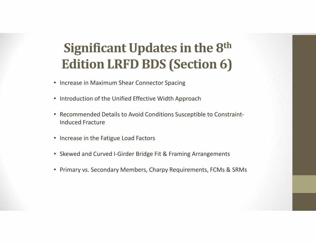
Significant Updates in the 8th
Edition LRFD BDS (Section 6)• Increase in Maximum Shear Connector Spacing
• Introduction of the Unified Effective Width Approach
• Recommended Details to Avoid Conditions Susceptible to Constraint-Induced Fracture
• Increase in the Fatigue Load Factors
• Skewed and Curved I-Girder Bridge Fit & Framing Arrangements
• Primary vs. Secondary Members, Charpy Requirements, FCMs & SRMs
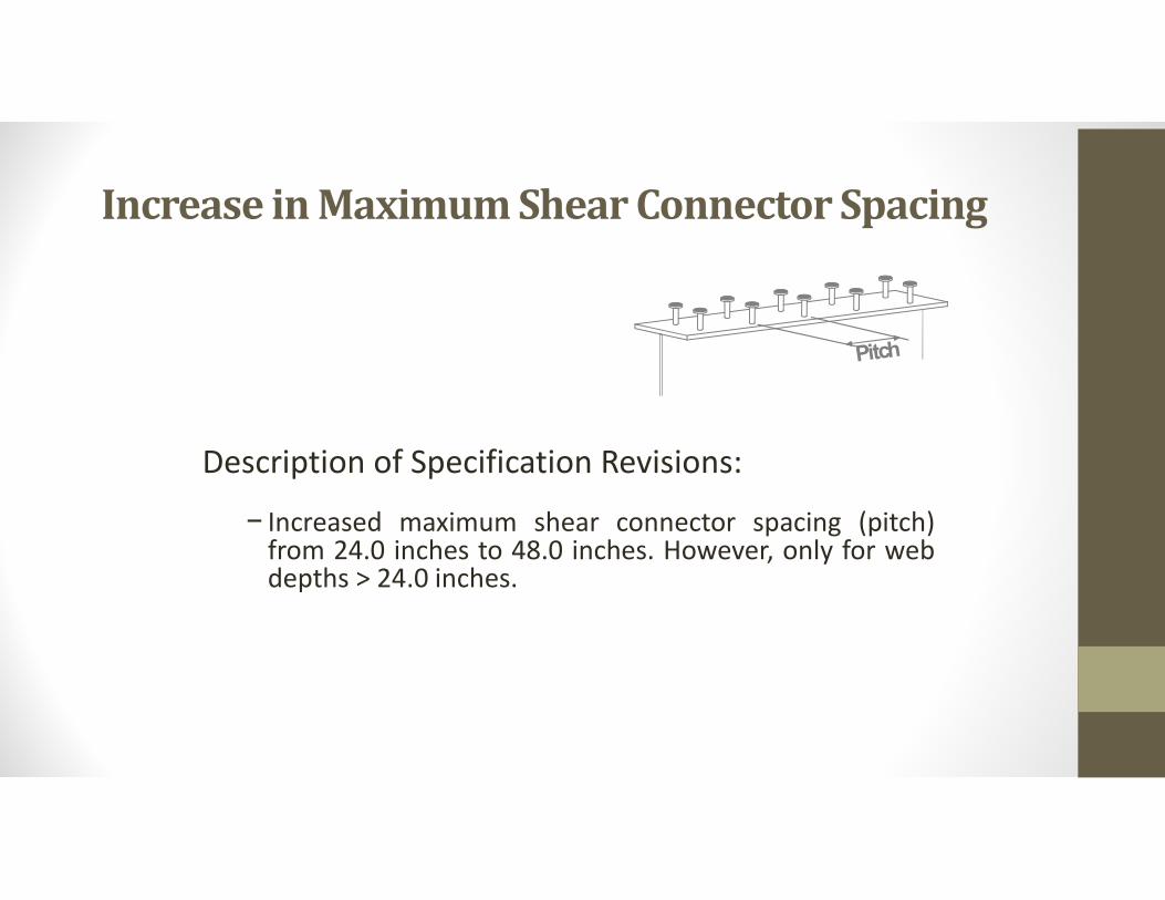
Increase in Maximum Shear Connector Spacing
Description of Specification Revisions:
− Increased maximum shear connector spacing (pitch)from 24.0 inches to 48.0 inches. However, only for webdepths > 24.0 inches.
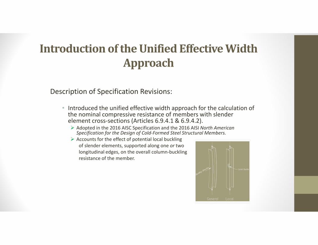
Introduction of the Unified Effective Width Approach
Description of Specification Revisions:
• Introduced the unified effective width approach for the calculation of the nominal compressive resistance of members with slender element cross-sections (Articles 6.9.4.1 & 6.9.4.2). Adopted in the 2016 AISC Specification and the 2016 AISI North American
Specification for the Design of Cold-Formed Steel Structural Members. Accounts for the effect of potential local buckling
of slender elements, supported along one or two longitudinal edges, on the overall column-buckling resistance of the member.
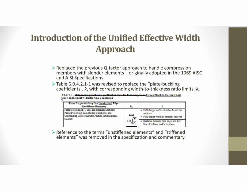
Introduction of the Unified Effective Width Approach
Replaced the previous Q-factor approach to handle compression members with slender elements – originally adopted in the 1969 AISC and AISI Specifications.
Table 6.9.4.2.1-1 was revised to replace the “plate-buckling coefficients”, k, with corresponding width-to-thickness ratio limits, λr.
Reference to the terms “unstiffened elements” and “stiffened elements” was removed in the specification and commentary.
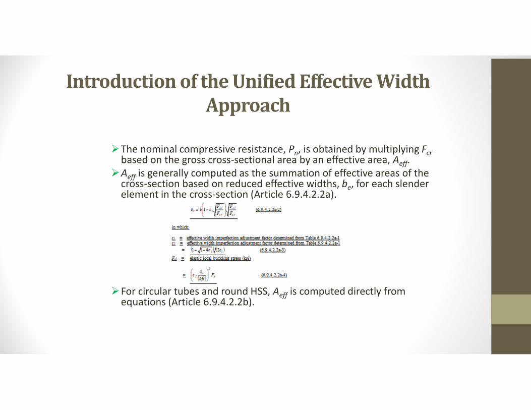
Introduction of the Unified Effective Width Approach
The nominal compressive resistance, Pn, is obtained by multiplying Fcrbased on the gross cross-sectional area by an effective area, Aeff.
Aeff is generally computed as the summation of effective areas of the cross-section based on reduced effective widths, be, for each slender element in the cross-section (Article 6.9.4.2.2a).
For circular tubes and round HSS, Aeff is computed directly from equations (Article 6.9.4.2.2b).
Recommended Details to Avoid Conditions Susceptible to Constraint-Induced Fracture
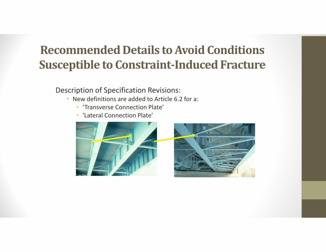
Description of Specification Revisions:• New definitions are added to Article 6.2 for a:
• ‘Transverse Connection Plate’ • ‘Lateral Connection Plate’
Recommended Details to Avoid Conditions Susceptible to Constraint-Induced Fracture
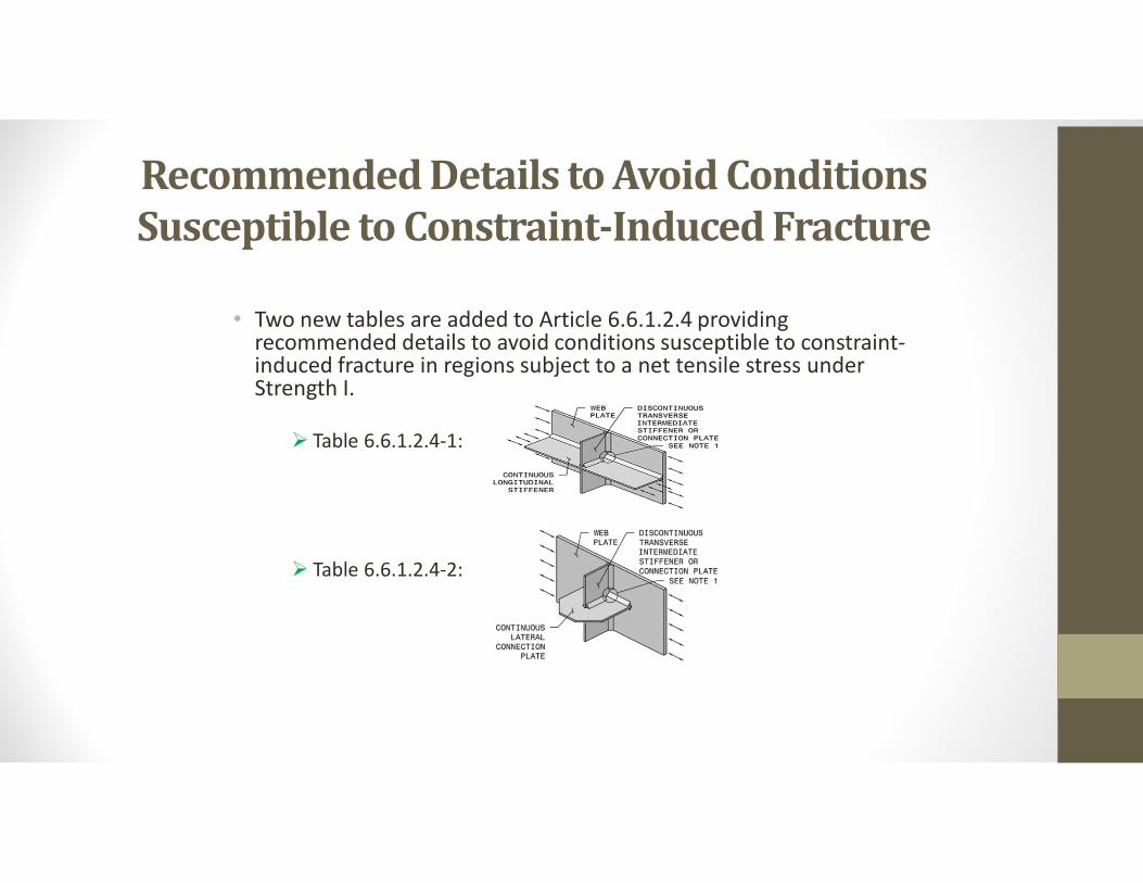
• Two new tables are added to Article 6.6.1.2.4 providing recommended details to avoid conditions susceptible to constraint-induced fracture in regions subject to a net tensile stress under Strength I.
Table 6.6.1.2.4-1:
Table 6.6.1.2.4-2:
Recommended Details to Avoid Conditions Susceptible to Constraint-Induced Fracture
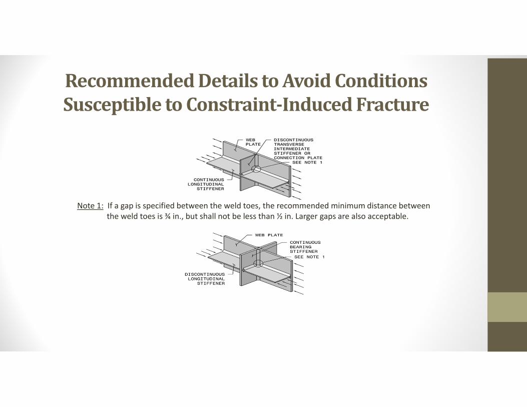
Note 1: If a gap is specified between the weld toes, the recommended minimum distance between the weld toes is ¾ in., but shall not be less than ½ in. Larger gaps are also acceptable.
Increase in the Fatigue Load Factors
Description of Specification Revisions:
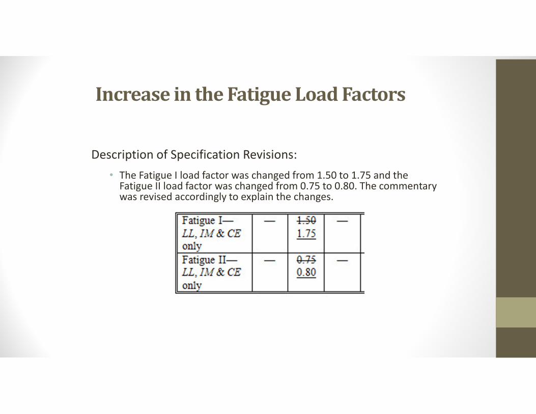
• The Fatigue I load factor was changed from 1.50 to 1.75 and the Fatigue II load factor was changed from 0.75 to 0.80. The commentary was revised accordingly to explain the changes.
Increase in the Fatigue Load Factors
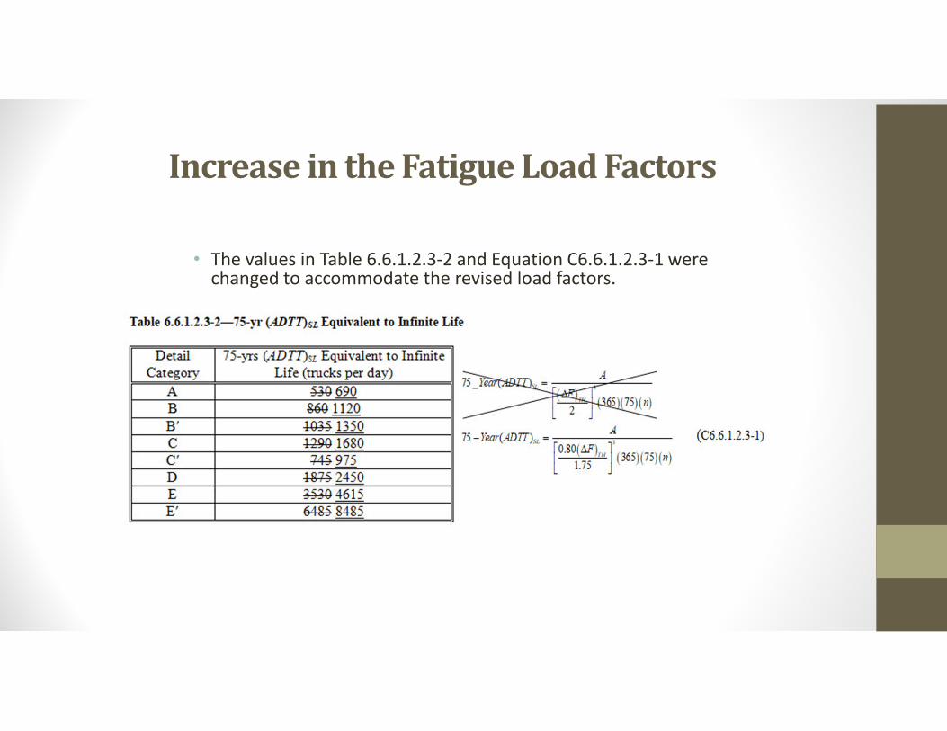
• The values in Table 6.6.1.2.3-2 and Equation C6.6.1.2.3-1 were changed to accommodate the revised load factors.
Increase in the Fatigue Load Factors
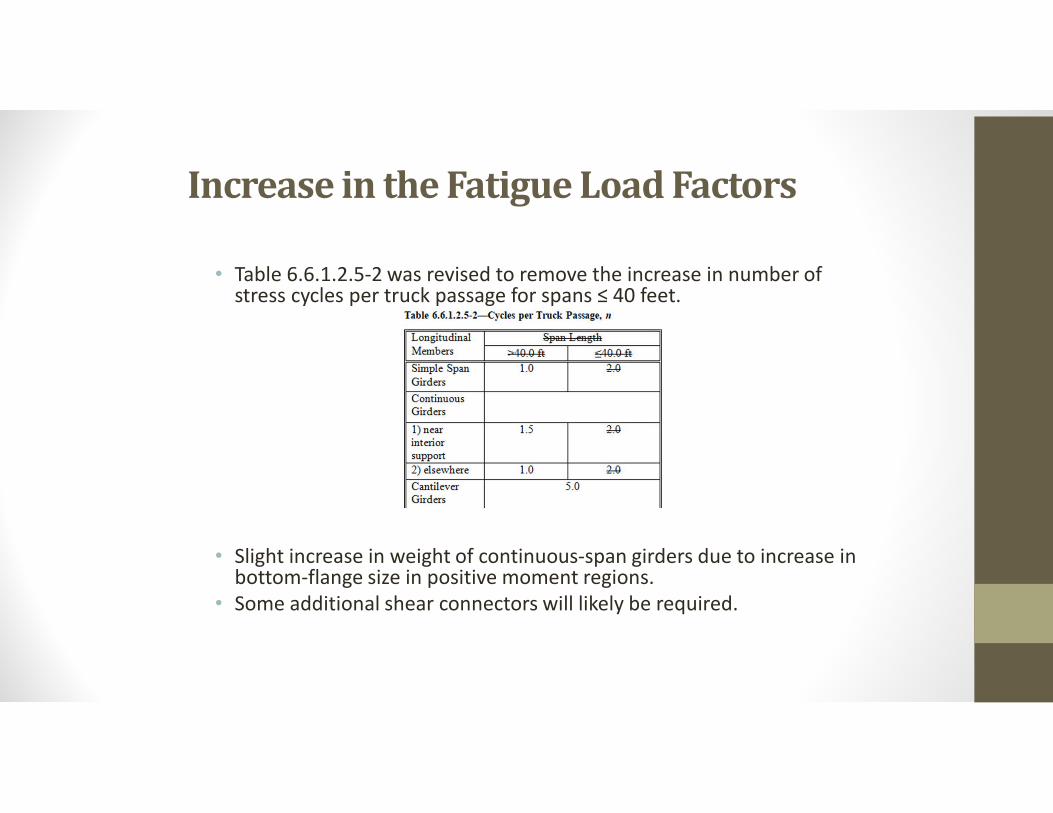
• Table 6.6.1.2.5-2 was revised to remove the increase in number of stress cycles per truck passage for spans ≤ 40 feet.
• Slight increase in weight of continuous-span girders due to increase in bottom-flange size in positive moment regions.
• Some additional shear connectors will likely be required.
Skewed and Curved I-Girder Bridge Fit & Framing Arrangements
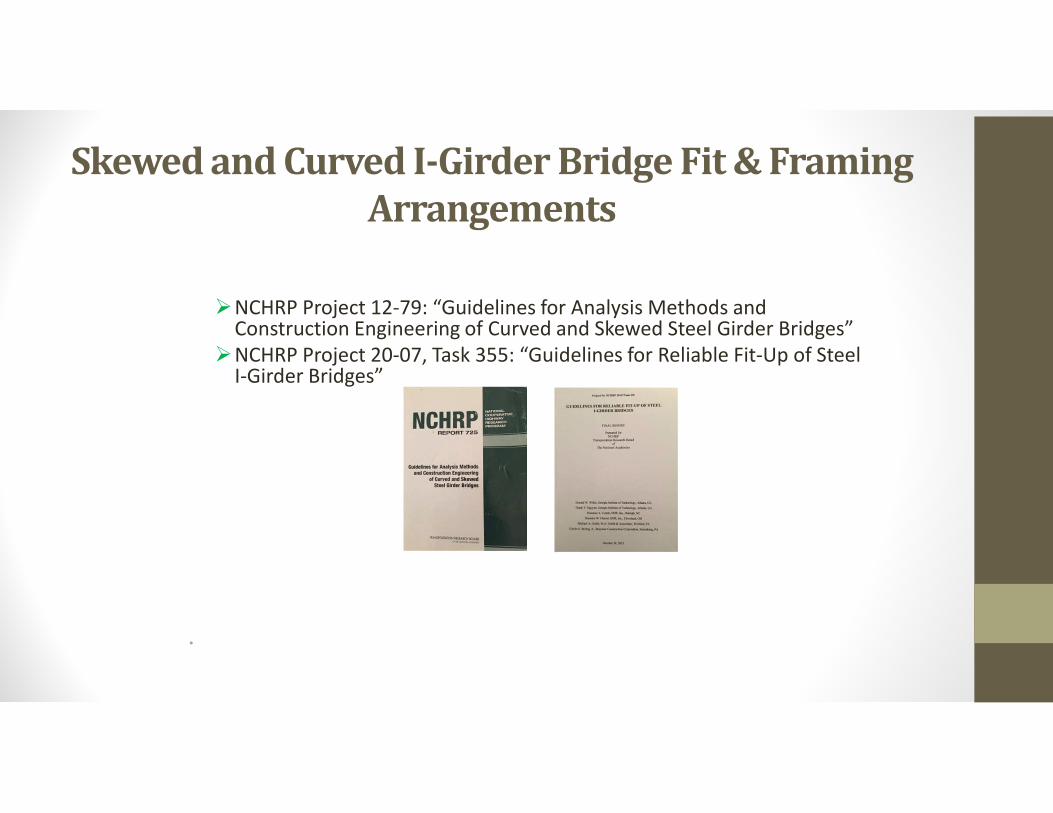
NCHRP Project 12-79: “Guidelines for Analysis Methods and Construction Engineering of Curved and Skewed Steel Girder Bridges”
NCHRP Project 20-07, Task 355: “Guidelines for Reliable Fit-Up of Steel I-Girder Bridges”
•
Skewed and Curved I-Girder Bridge Fit & Framing Arrangements
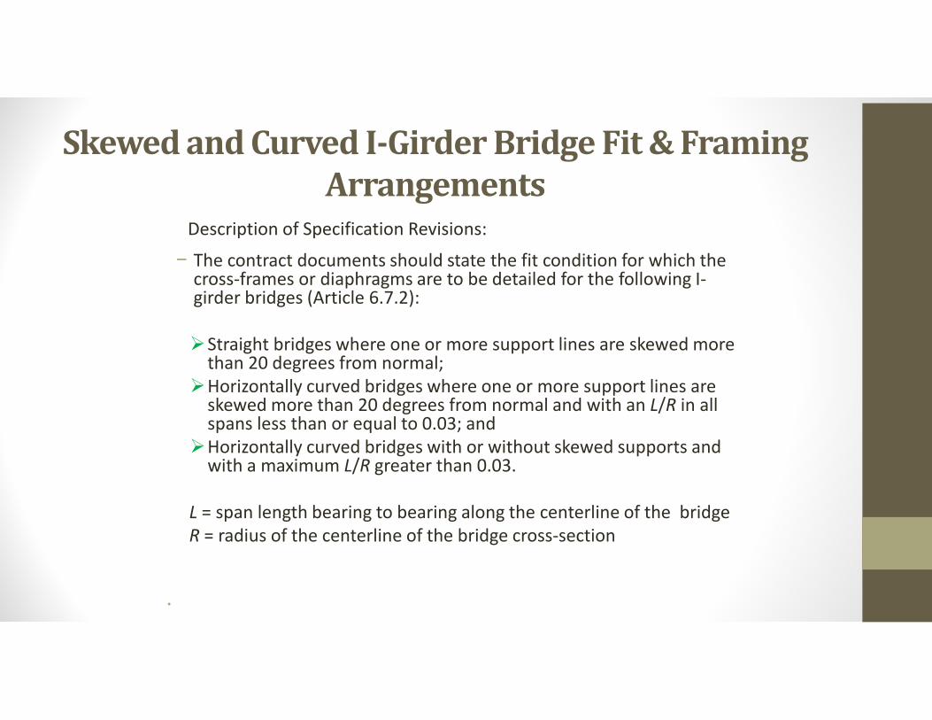
− The contract documents should state the fit condition for which the cross-frames or diaphragms are to be detailed for the following I-girder bridges (Article 6.7.2):
Straight bridges where one or more support lines are skewed more than 20 degrees from normal;
Horizontally curved bridges where one or more support lines are skewed more than 20 degrees from normal and with an L/R in all spans less than or equal to 0.03; and
Horizontally curved bridges with or without skewed supports and with a maximum L/R greater than 0.03.
L = span length bearing to bearing along the centerline of the bridge R = radius of the centerline of the bridge cross-section
•
Description of Specification Revisions:
Skewed and Curved I-Girder Bridge Fit & Framing Arrangements
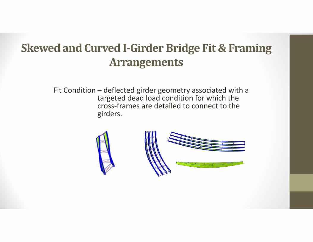
Fit Condition – deflected girder geometry associated with a targeted dead load condition for which the cross-frames are detailed to connect to the girders.
Skewed and Curved I-Girder Bridge Fit & Framing Arrangements
Summary Full Document
Skewed and Curved I-Girder Bridge Fit & Framing Arrangements
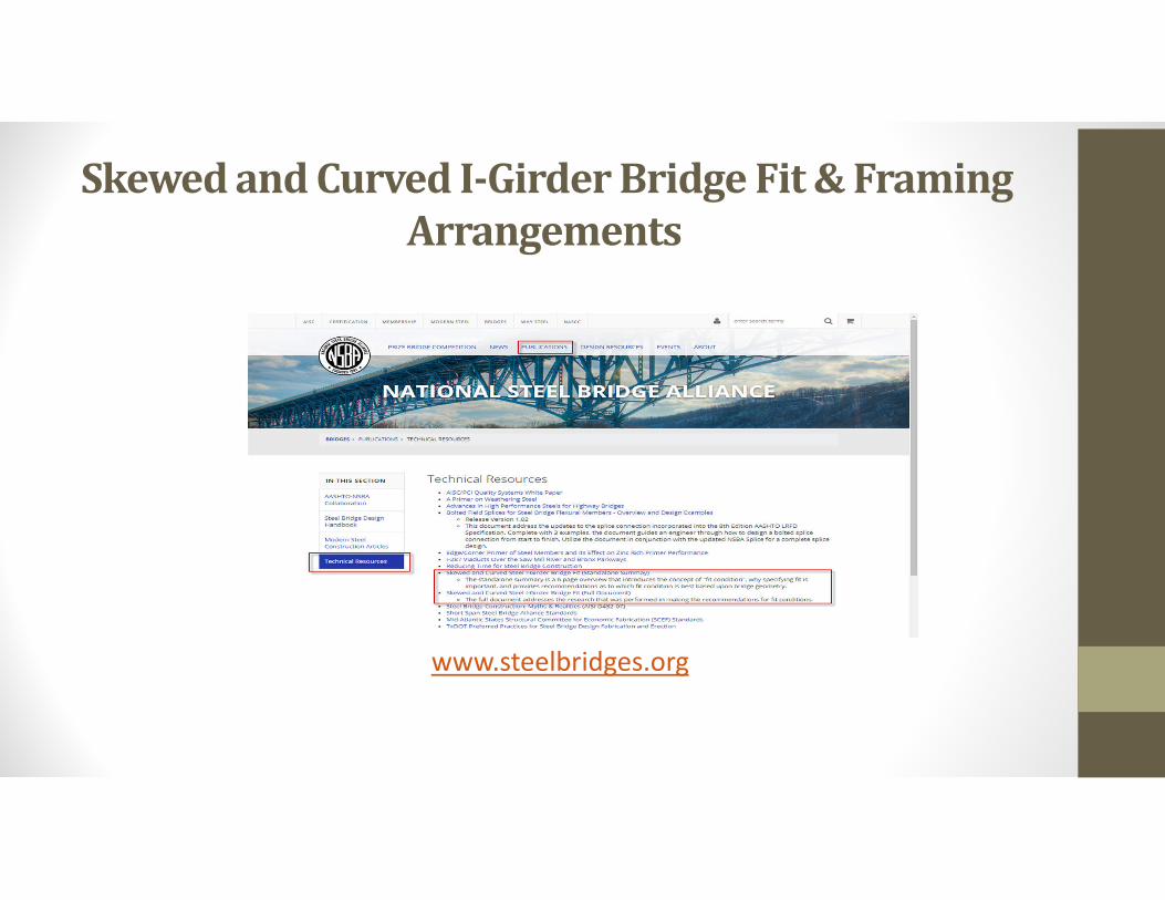
www.steelbridges.org
Skewed and Curved I-Girder Bridge Fit & Framing Arrangements
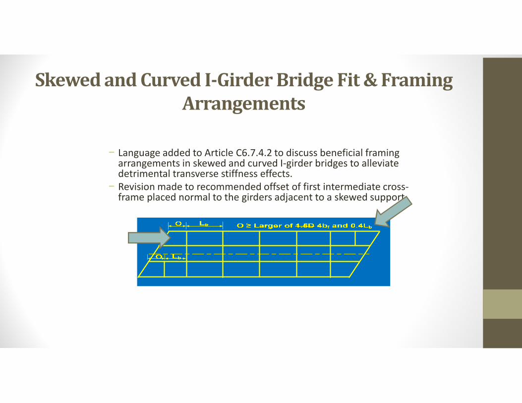
− Language added to Article C6.7.4.2 to discuss beneficial framing arrangements in skewed and curved I-girder bridges to alleviate detrimental transverse stiffness effects.
− Revision made to recommended offset of first intermediate cross-frame placed normal to the girders adjacent to a skewed support.
Skewed and Curved I-Girder Bridge Fit & Framing Arrangements
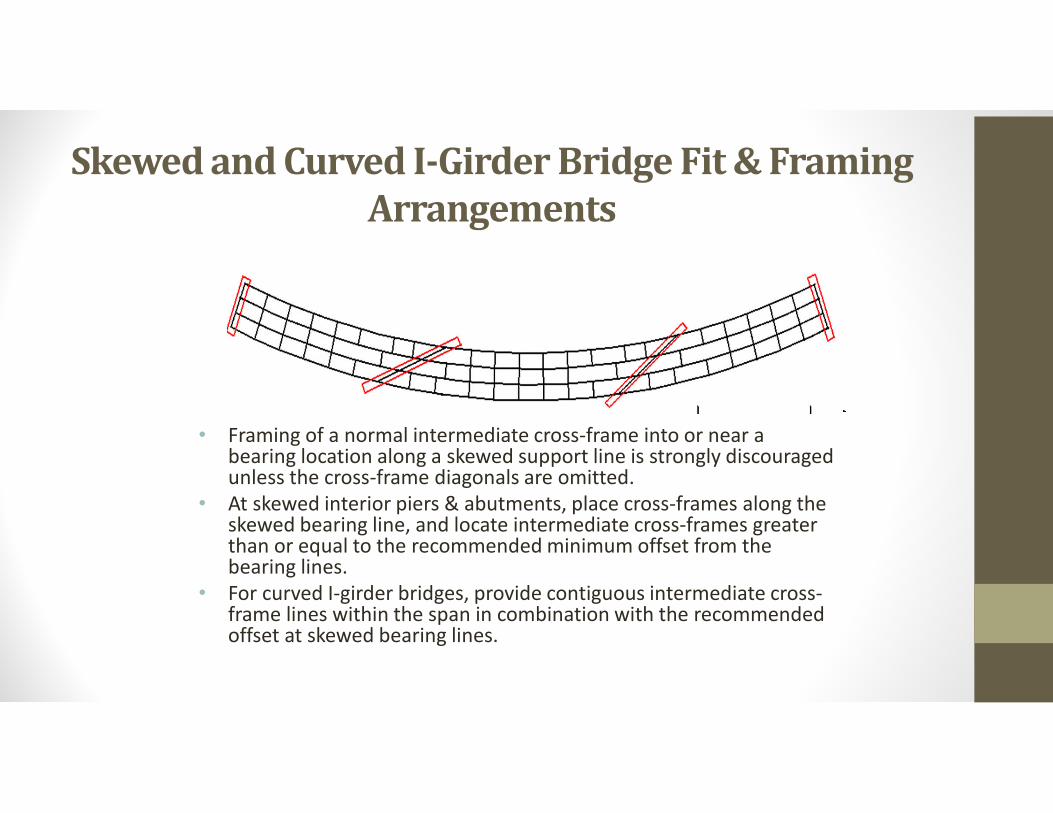
• Framing of a normal intermediate cross-frame into or near a bearing location along a skewed support line is strongly discouraged unless the cross-frame diagonals are omitted.
• At skewed interior piers & abutments, place cross-frames along the skewed bearing line, and locate intermediate cross-frames greater than or equal to the recommended minimum offset from the bearing lines.
• For curved I-girder bridges, provide contiguous intermediate cross-frame lines within the span in combination with the recommended offset at skewed bearing lines.
Primary vs. Secondary Members, Charpy Requirements, FCMs & SRMs
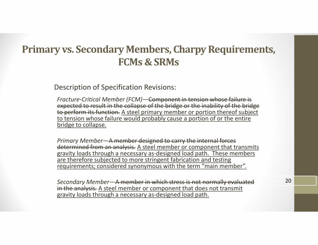
Description of Specification Revisions:
Fracture-Critical Member (FCM)—Component in tension whose failure is expected to result in the collapse of the bridge or the inability of the bridge to perform its function. A steel primary member or portion thereof subject to tension whose failure would probably cause a portion of or the entire bridge to collapse.
Primary Member—A member designed to carry the internal forces determined from an analysis. A steel member or component that transmits gravity loads through a necessary as-designed load path. These members are therefore subjected to more stringent fabrication and testing requirements; considered synonymous with the term “main member”.
Secondary Member—A member in which stress is not normally evaluated in the analysis. A steel member or component that does not transmit gravity loads through a necessary as-designed load path.
20
Primary vs. Secondary Members, Charpy Requirements, FCMs & SRMs
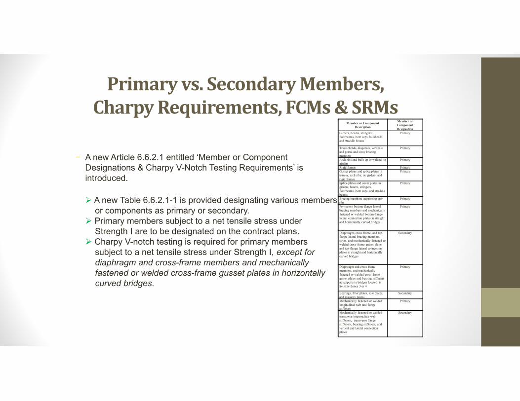
− A new Article 6.6.2.1 entitled ‘Member or Component Designations & Charpy V-Notch Testing Requirements’ is introduced.
A new Table 6.6.2.1-1 is provided designating various membersor components as primary or secondary.
Primary members subject to a net tensile stress under Strength I are to be designated on the contract plans.
Charpy V-notch testing is required for primary members subject to a net tensile stress under Strength I, except for diaphragm and cross-frame members and mechanically fastened or welded cross-frame gusset plates in horizontally curved bridges.
Member or Component Description
Member or Component Designation
Girders, beams, stringers, floorbeams, bent caps, bulkheads, and straddle beams
Primary
Truss chords, diagonals, verticals, and portal and sway bracing members
Primary
Arch ribs and built-up or welded tie girders
Primary
Rigid frames PrimaryGusset plates and splice plates in trusses, arch ribs, tie girders, and rigid frames
Primary
Splice plates and cover plates in girders, beams, stringers, floorbeams, bent caps, and straddle beams
Primary
Bracing members supporting arch ribs
Primary
Permanent bottom-flange lateral bracing members and mechanically fastened or welded bottom-flange lateral connection plates in straight and horizontally curved bridges
Primary
Diaphragm, cross-frame, and top-flange lateral bracing members, struts, and mechanically fastened or welded cross-frame gusset plates and top-flange lateral connection plates in straight and horizontally curved bridges
Secondary
Diaphragm and cross-frame members, and mechanically fastened or welded cross-frame gusset plates and bearing stiffeners at supports in bridges located in Seismic Zones 3 or 4
Primary
Bearings, filler plates, sole plates, and masonry plates
Secondary
Mechanically fastened or welded longitudinal web and flange stiffeners
Primary
Mechanically fastened or welded transverse intermediate web stiffeners, transverse flange stiffeners, bearing stiffeners, and vertical and lateral connection plates
Secondary
Primary vs. Secondary Members, CharpyRequirements, FCMs & SRMs
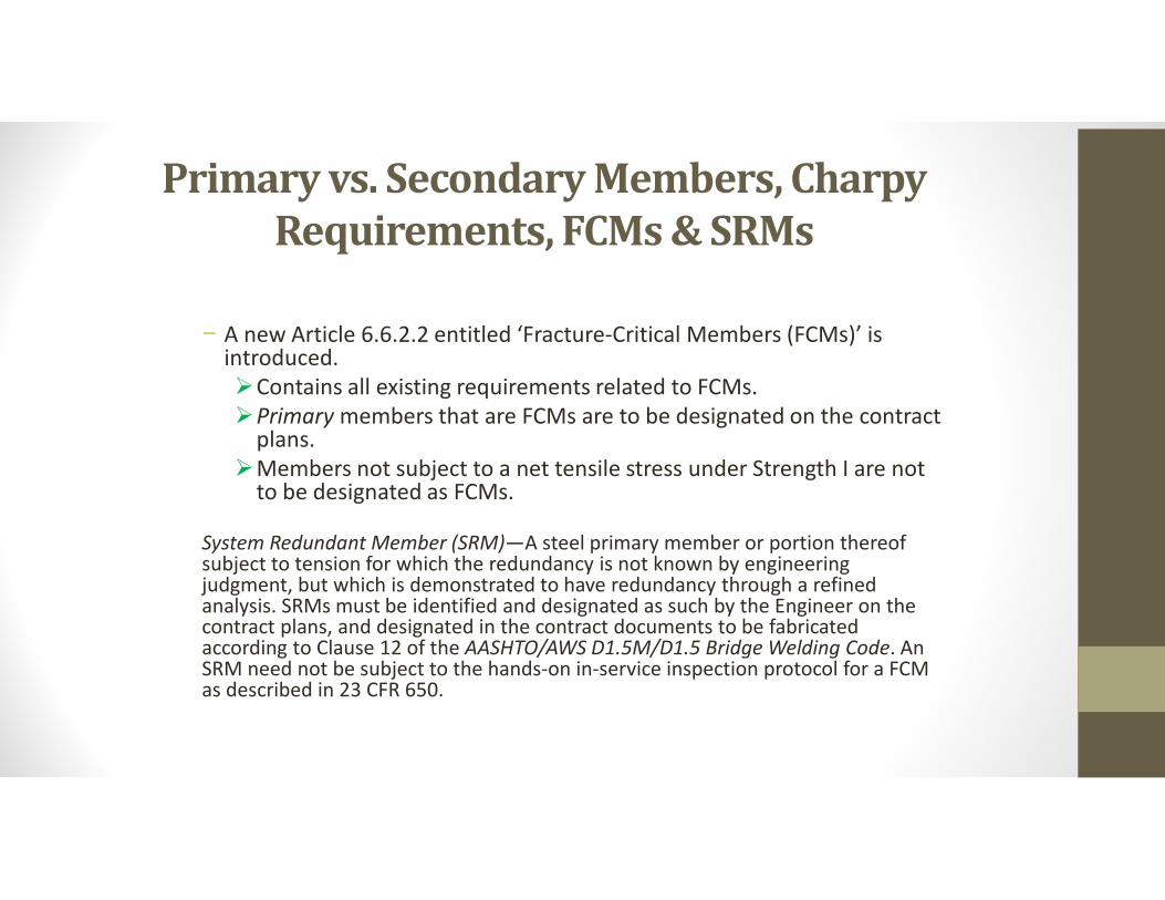
− A new Article 6.6.2.2 entitled ‘Fracture-Critical Members (FCMs)’ is introduced.Contains all existing requirements related to FCMs.Primary members that are FCMs are to be designated on the contract
plans.Members not subject to a net tensile stress under Strength I are not
to be designated as FCMs.
System Redundant Member (SRM)—A steel primary member or portion thereof subject to tension for which the redundancy is not known by engineering judgment, but which is demonstrated to have redundancy through a refined analysis. SRMs must be identified and designated as such by the Engineer on the contract plans, and designated in the contract documents to be fabricated according to Clause 12 of the AASHTO/AWS D1.5M/D1.5 Bridge Welding Code. An SRM need not be subject to the hands-on in-service inspection protocol for a FCM as described in 23 CFR 650.
Significant Updates to Appear in the 9th Edition LRFD BDS
• Revisions to the L/85 Guideline
• Improvements to Rb for Longitudinally Stiffened Girders
• Revisions to Fatigue Detail Table 6.6.1.2.3-1
• Revisions to the Flexural Design Provisions for Tees & Double Angles
• Variable Web Depth Members
• Design Provisions for Noncomposite Box-Section Members
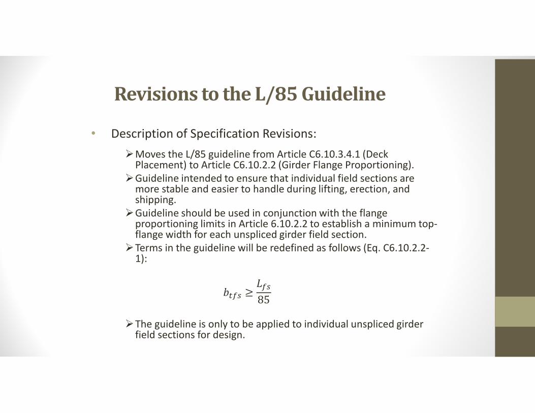
Revisions to the L/85 Guideline
• Description of Specification Revisions:
Moves the L/85 guideline from Article C6.10.3.4.1 (Deck Placement) to Article C6.10.2.2 (Girder Flange Proportioning).
Guideline intended to ensure that individual field sections are more stable and easier to handle during lifting, erection, and shipping.
Guideline should be used in conjunction with the flange proportioning limits in Article 6.10.2.2 to establish a minimum top-flange width for each unspliced girder field section.
Terms in the guideline will be redefined as follows (Eq. C6.10.2.2-1):
���� ≥���
85
The guideline is only to be applied to individual unspliced girder field sections for design.
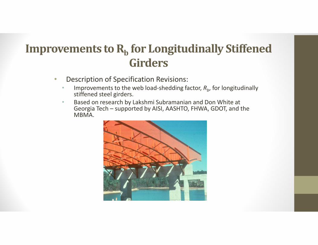
Improvements to Rb for Longitudinally Stiffened Girders
• Description of Specification Revisions:• Improvements to the web load-shedding factor, Rb, for longitudinally
stiffened steel girders.• Based on research by Lakshmi Subramanian and Don White at
Georgia Tech – supported by AISI, AASHTO, FHWA, GDOT, and the MBMA.
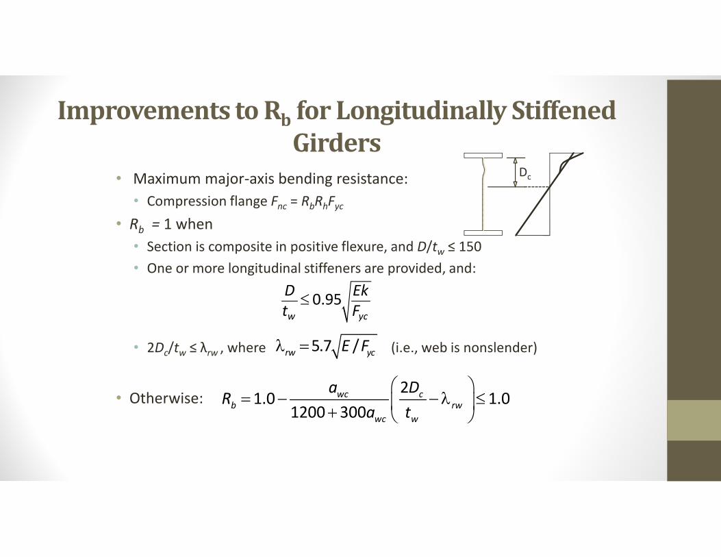
Improvements to Rb for Longitudinally Stiffened Girders
• Maximum major-axis bending resistance:
• Compression flange Fnc = RbRhFyc
• Rb = 1 when
• Section is composite in positive flexure, and D/tw ≤ 150
• One or more longitudinal stiffeners are provided, and:
• 2Dc/tw ≤ λrw , where (i.e., web is nonslender)
• Otherwise:
0.95w yc
D Ekt F
21.0 1.0
1200 300wc c
b rw
wc w
a DR
a t
5.7 /rw ycE F
Dc
Improvements to Rb for Longitudinally Stiffened Girders
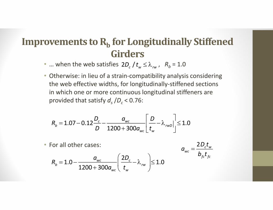
• … when the web satisfies , Rb = 1.0
• Otherwise: in lieu of a strain-compatibility analysis considering the web effective widths, for longitudinally-stiffened sections in which one or more continuous longitudinal stiffeners are provided that satisfy ds /Dc < 0.76:
• For all other cases:
1.07 0.12 1.01200 300
c wcb rwD
wc w
D a DR
D a t
2 /c w rwD t
21.0 1.0
1200 300wc c
b rw
wc w
a DR
a t
2 c wwc
fc fc
D ta
b t
Improvements to Rb for Longitudinally Stiffened Girders
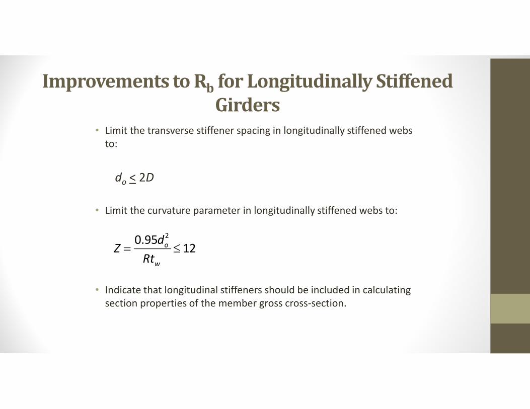
• Limit the transverse stiffener spacing in longitudinally stiffened webs to:
do < 2D
• Limit the curvature parameter in longitudinally stiffened webs to:
• Indicate that longitudinal stiffeners should be included in calculating section properties of the member gross cross-section.
20.9512o
w
dZ
Rt
Revisions to Fatigue Detail Table 6.6.1.2.3-1
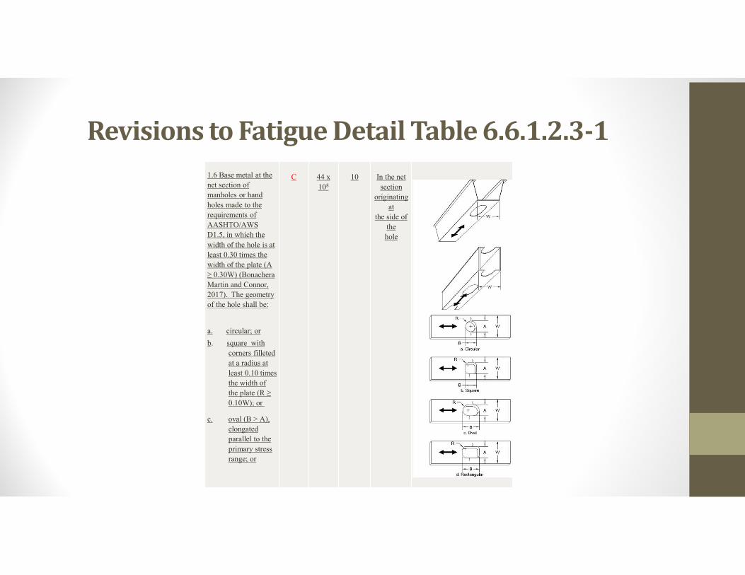
1.6 Base metal at the
net section of
manholes or hand
holes made to the
requirements of
AASHTO/AWS
D1.5, in which the
width of the hole is at
least 0.30 times the
width of the plate (A
≥ 0.30W) (Bonachera
Martin and Connor,
2017). The geometry
of the hole shall be:
a. circular; or
b. square with
corners filleted
at a radius at
least 0.10 times
the width of
the plate (R ≥
0.10W); or
c. oval (B > A),
elongated
parallel to the
primary stress
range; or
C 44 x
108
10 In the net
section
originating
at
the side of
the
hole
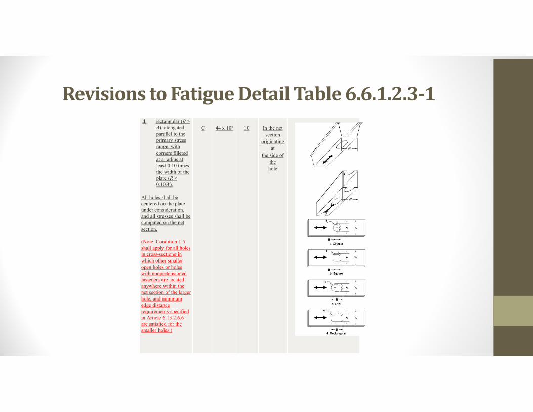
Revisions to Fatigue Detail Table 6.6.1.2.3-1d. rectangular (B >
A), elongated parallel to the primary stress range, with corners filleted at a radius at least 0.10 times the width of the plate (R ≥ 0.10W).
All holes shall be centered on the plate under consideration, and all stresses shall be computed on the net section.
(Note: Condition 1.5 shall apply for all holes in cross-sections in which other smaller open holes or holes with nonpretensionedfasteners are located anywhere within the net section of the larger hole, and minimum edge distance requirements specified in Article 6.13.2.6.6 are satisfied for the smaller holes.)
C 44 x 108 10 In the net
section
originating
at
the side of
the
hole
Revisions to Fatigue Detail Table 6.6.1.2.3-1
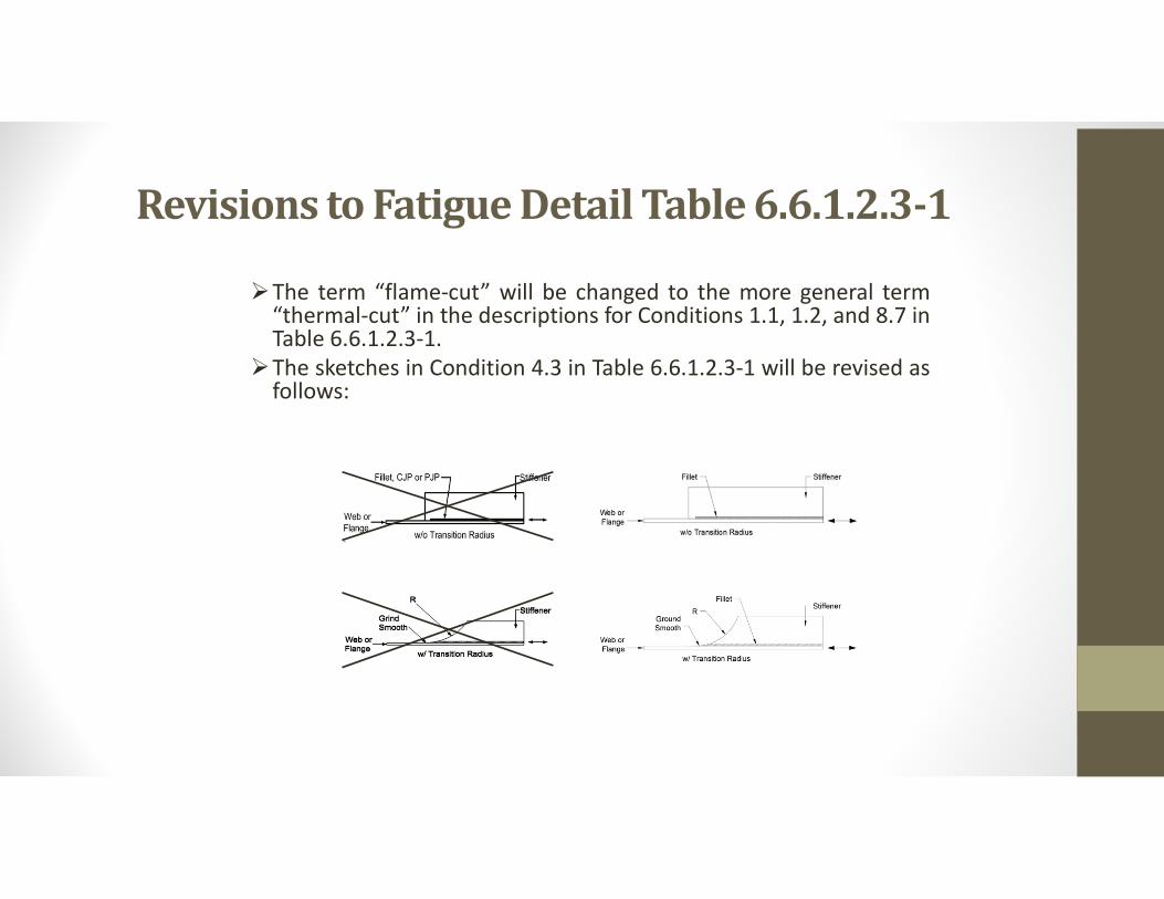
The term “flame-cut” will be changed to the more general term“thermal-cut” in the descriptions for Conditions 1.1, 1.2, and 8.7 inTable 6.6.1.2.3-1.
The sketches in Condition 4.3 in Table 6.6.1.2.3-1 will be revised asfollows:
Revisions to the Flexural Design Provisions for Tees & Double Angles
Description of Specification Revisions:
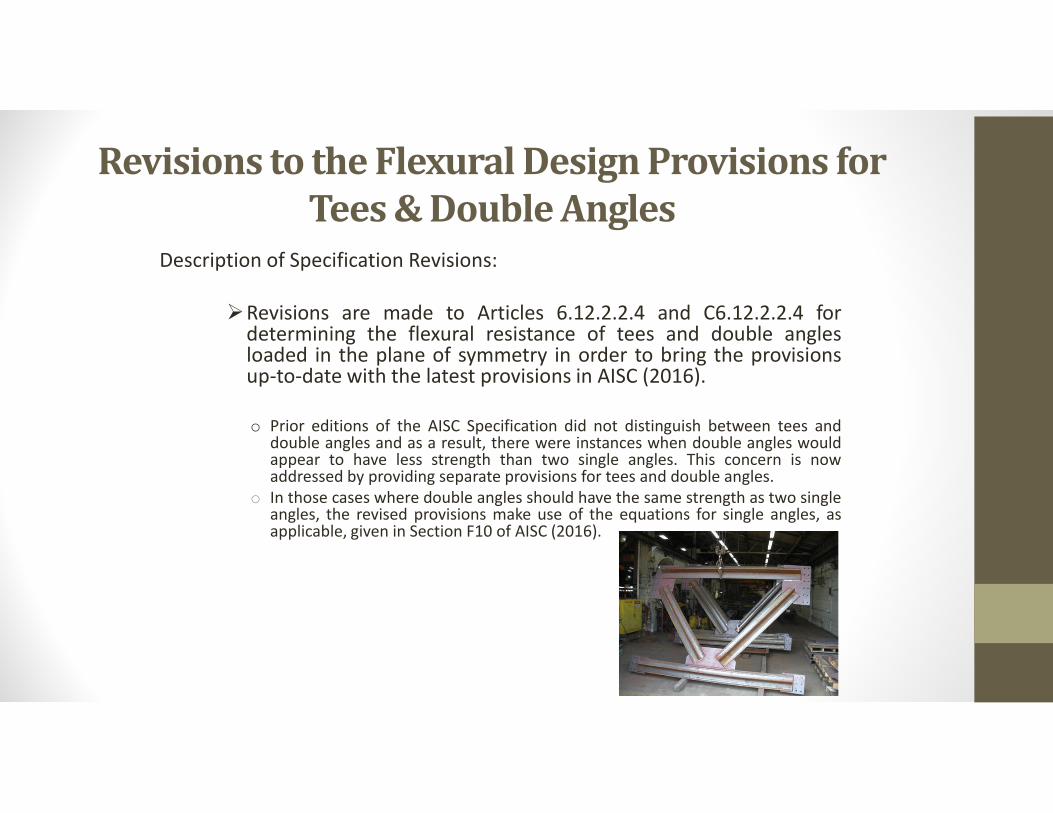
Revisions are made to Articles 6.12.2.2.4 and C6.12.2.2.4 fordetermining the flexural resistance of tees and double anglesloaded in the plane of symmetry in order to bring the provisionsup-to-date with the latest provisions in AISC (2016).
o Prior editions of the AISC Specification did not distinguish between tees anddouble angles and as a result, there were instances when double angles wouldappear to have less strength than two single angles. This concern is nowaddressed by providing separate provisions for tees and double angles.
o In those cases where double angles should have the same strength as two singleangles, the revised provisions make use of the equations for single angles, asapplicable, given in Section F10 of AISC (2016).
Revisions to the Flexural Design Provisions for Tees & Double Angles
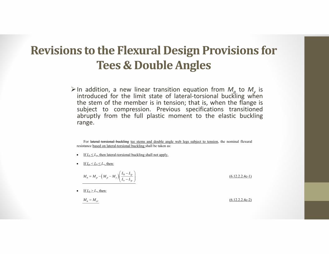
In addition, a new linear transition equation from Mp to My isintroduced for the limit state of lateral-torsional buckling whenthe stem of the member is in tension; that is, when the flange issubject to compression. Previous specifications transitionedabruptly from the full plastic moment to the elastic bucklingrange.
For lateral torsional buckling tee stems and double angle web legs subject to tension, the nominal flexural resistance based on lateral-torsional buckling shall be taken as: If Lb ≤ Lp, then lateral-torsional buckling shall not apply. If Lp < Lb ≤ Lr, then:
b pn p p y
r p
L LM M M M
L L
(6.12.2.2.4c-1)
If Lb > Lr, then:
n crM M (6.12.2.2.4c-2)
Variable Web Depth Members
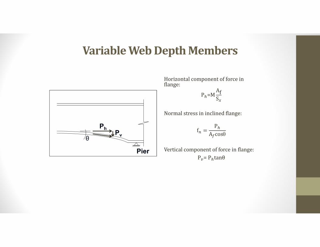
Horizontal component of force in flange:
P�=MAfS�
Normal stress in inclined flange:
f� =P�
A�cosq
Vertical component of force in flange:
P�= P�tanθPier
θ
PhPv
Variable Web Depth Members
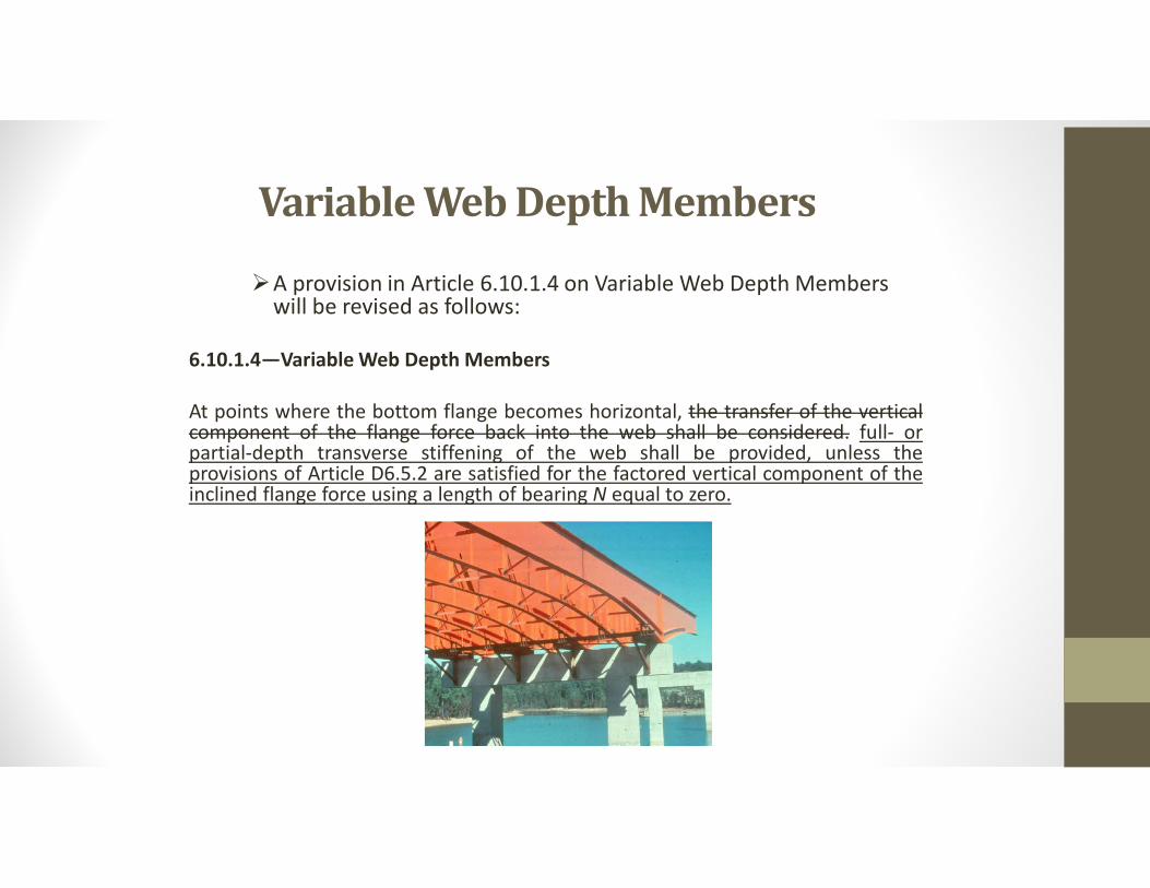
A provision in Article 6.10.1.4 on Variable Web Depth Members will be revised as follows:
6.10.1.4—Variable Web Depth Members
At points where the bottom flange becomes horizontal, the transfer of the verticalcomponent of the flange force back into the web shall be considered. full- orpartial-depth transverse stiffening of the web shall be provided, unless theprovisions of Article D6.5.2 are satisfied for the factored vertical component of theinclined flange force using a length of bearing N equal to zero.
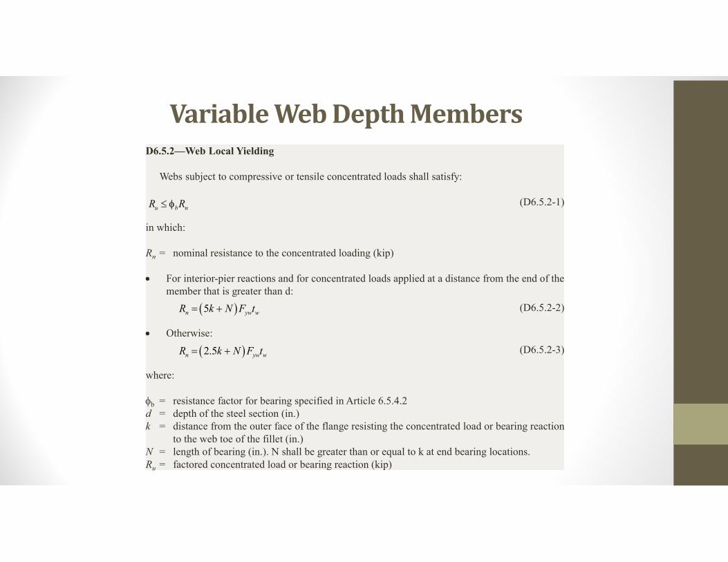
Variable Web Depth MembersD6.5.2—Web Local Yielding
Webs subject to compressive or tensile concentrated loads shall satisfy:
(D6.5.2-1)
in which:
Rn = nominal resistance to the concentrated loading (kip)
For interior-pier reactions and for concentrated loads applied at a distance from the end of themember that is greater than d:
(D6.5.2-2)
Otherwise:
(D6.5.2-3)
where:
b = resistance factor for bearing specified in Article 6.5.4.2d = depth of the steel section (in.)k = distance from the outer face of the flange resisting the concentrated load or bearing reaction
to the web toe of the fillet (in.)N = length of bearing (in.). N shall be greater than or equal to k at end bearing locations.Ru = factored concentrated load or bearing reaction (kip)
u b nR R
5n yw wR k N F t
2.5n yw wR k N F t
Variable Web Depth Members
Design Provisions for Noncomposite Box-Section Members
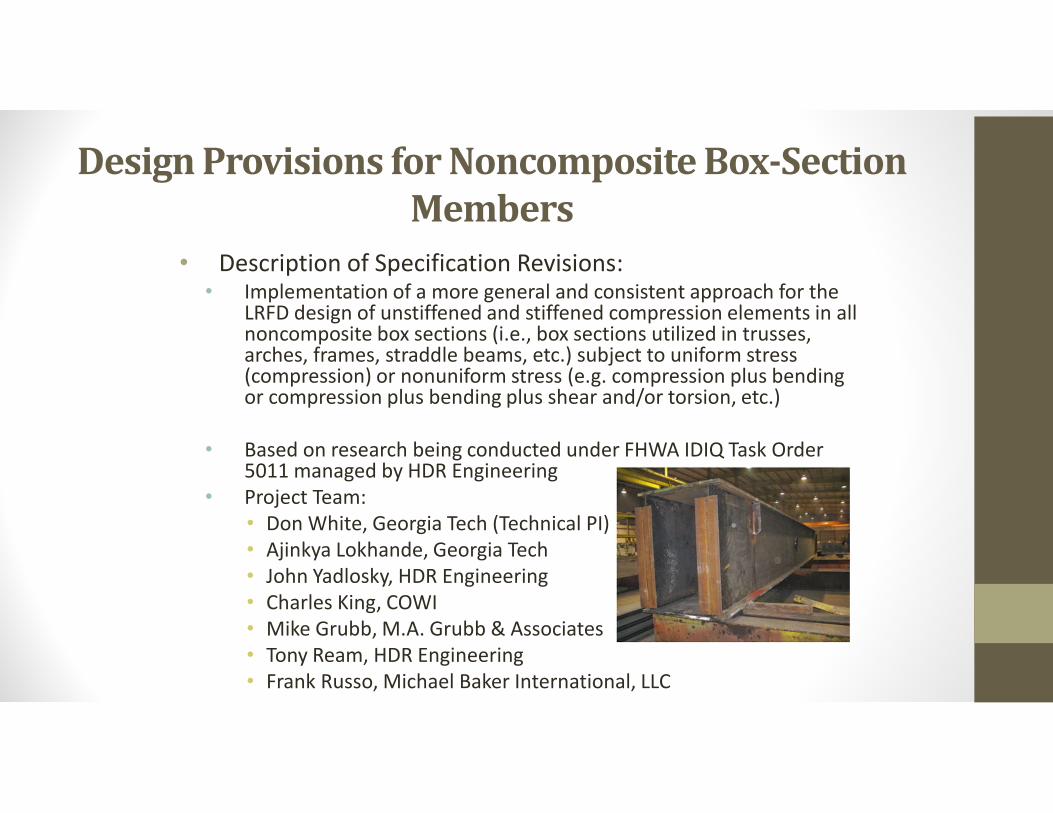
• Description of Specification Revisions:• Implementation of a more general and consistent approach for the
LRFD design of unstiffened and stiffened compression elements in all noncomposite box sections (i.e., box sections utilized in trusses, arches, frames, straddle beams, etc.) subject to uniform stress (compression) or nonuniform stress (e.g. compression plus bending or compression plus bending plus shear and/or torsion, etc.)
• Based on research being conducted under FHWA IDIQ Task Order 5011 managed by HDR Engineering
• Project Team:• Don White, Georgia Tech (Technical PI)• Ajinkya Lokhande, Georgia Tech• John Yadlosky, HDR Engineering• Charles King, COWI• Mike Grubb, M.A. Grubb & Associates• Tony Ream, HDR Engineering• Frank Russo, Michael Baker International, LLC
Design Provisions for Noncomposite Box-Section Members
• Benefits:
• Unstiffened and longitudinally stiffened noncomposite rectangular box-section members
• Built-up welded boxes, bolted boxes, and square and rectangular HSS
• Singly- and doubly-symmetric rectangular sections
• Homogeneous and hybrid sections
• All ranges of web and flange plate slenderness
• Use of an effective compression flange width in determining cross-section properties for boxes with noncompact and slender compression flanges (rely on post-buckling resistance)
• No theoretical shear buckling or plate local buckling permitted at the fatigue and service limit states, and for constructibility
• Use of a web plastification factor for sections having noncompact or compact webs (allows flexural resistances > Mye)
Design Provisions for Noncomposite Box-Section Members
• Benefits (cont.):• No need to check elastic LTB; accuracy with respect to the limit
state of inelastic LTB is significantly improved
• More efficient b/t limits for solid web arches
• Eliminates reliance on LFD Truss Guide Specifications
• Handles interaction of all force effects, including torsion
• Provides improved provisions for longitudinally stiffened flanges (new Appendix E6):
• Provide same set of equations for any number of stiffeners,transversely stiffened or not
• Take advantage of longitudinal stiffener, transverse stiffener andstiffened plate contributions to compression capacity
• Allows designer to easily determine from equation components iflongitudinally and/or transverse stiffening is effective
• Obtain more accurate and sufficient ratings for existing structures outside the slenderness limits of the current Specifications, or with inadequate stiffeners
Design Provisions for Noncomposite Box-Section Members
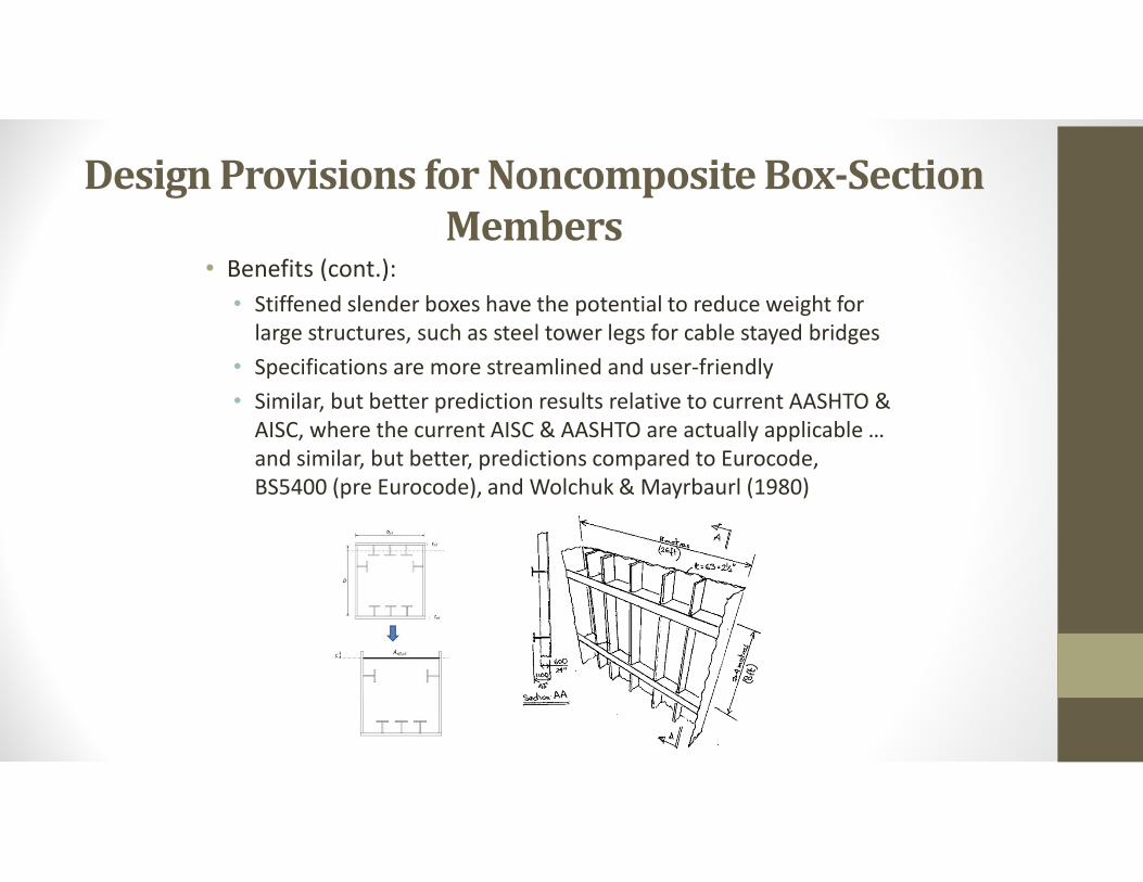
• Benefits (cont.):
• Stiffened slender boxes have the potential to reduce weight for large structures, such as steel tower legs for cable stayed bridges
• Specifications are more streamlined and user-friendly
• Similar, but better prediction results relative to current AASHTO & AISC, where the current AISC & AASHTO are actually applicable … and similar, but better, predictions compared to Eurocode, BS5400 (pre Eurocode), and Wolchuk & Mayrbaurl (1980)

• “Proposed LRFD Specifications for Noncomposite Steel Box-Section Members”
• FHWA-HIF-19-063 | July 2019
• (NCHRP 20-07/415)
• Expanded Commentary
• Additional provisions for specialized situations
• 3 Examples:
• Longitudinally Unstiffened Truss End Post
• Longitudinally Stiffened/Slender Tie Girder
• Longitudinally Stiffener Arch Rib
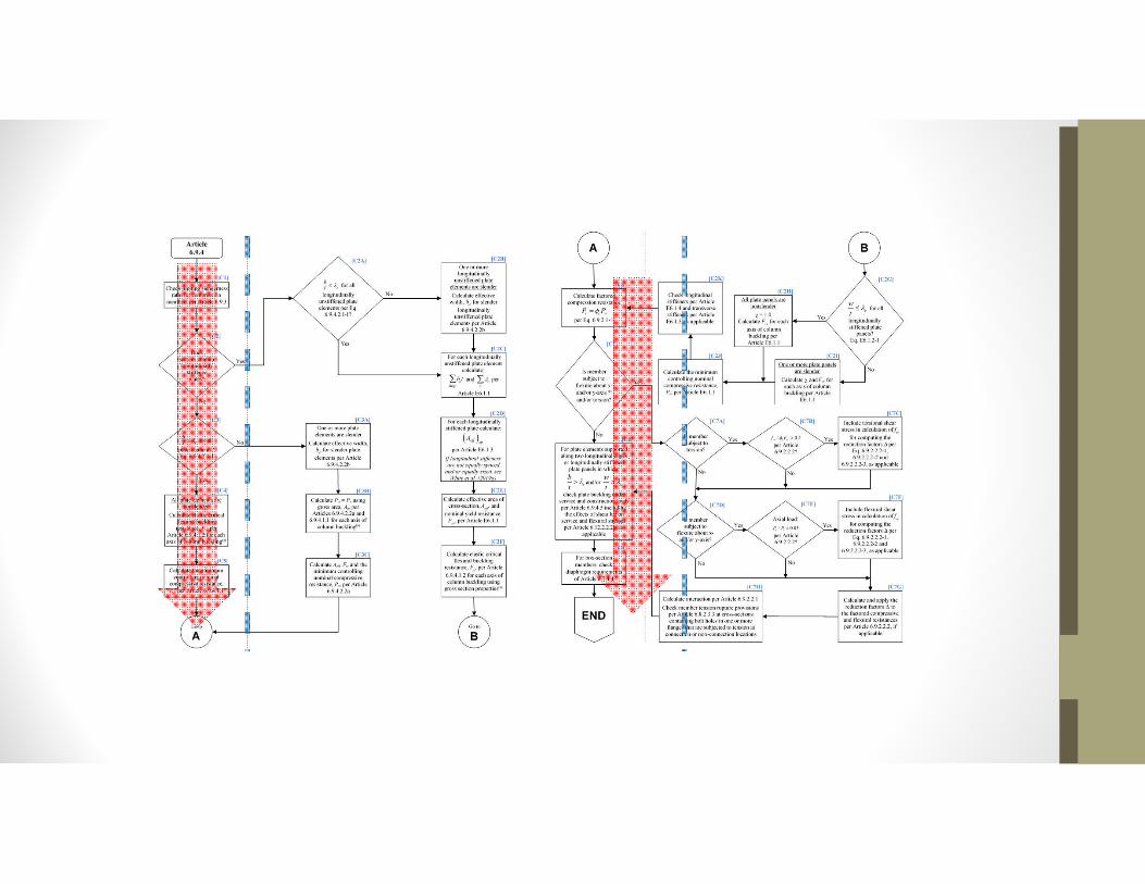
• 2 Flowcharts coordinated with Examples
• Compression & Flexural Resistance
Design Provisions for Noncomposite Box-Section Members
Questions?