Embed Size (px)
DESCRIPTION
notes
Citation preview
The George W. Woodruff School of Mechanical EngineeringThe George W. Woodruff School of Mechanical Engineering
ME3180ME3180
1
ME 3180: Machine Design
Helical Torsion Springs
Lecture Notes
The George W. Woodruff School of Mechanical EngineeringThe George W. Woodruff School of Mechanical Engineering
ME3180ME3180
2
Helical Torsion Springs
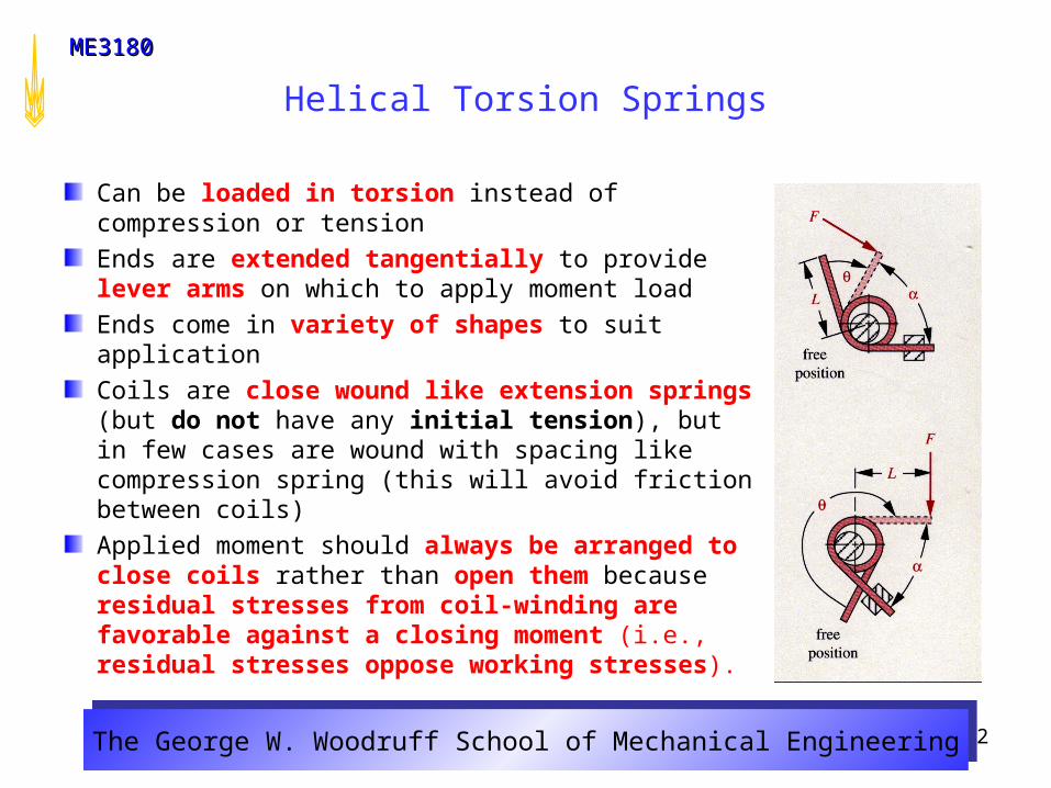
Can be loaded in torsion instead of compression or tension
Ends are extended tangentially to provide lever arms on which to apply moment load
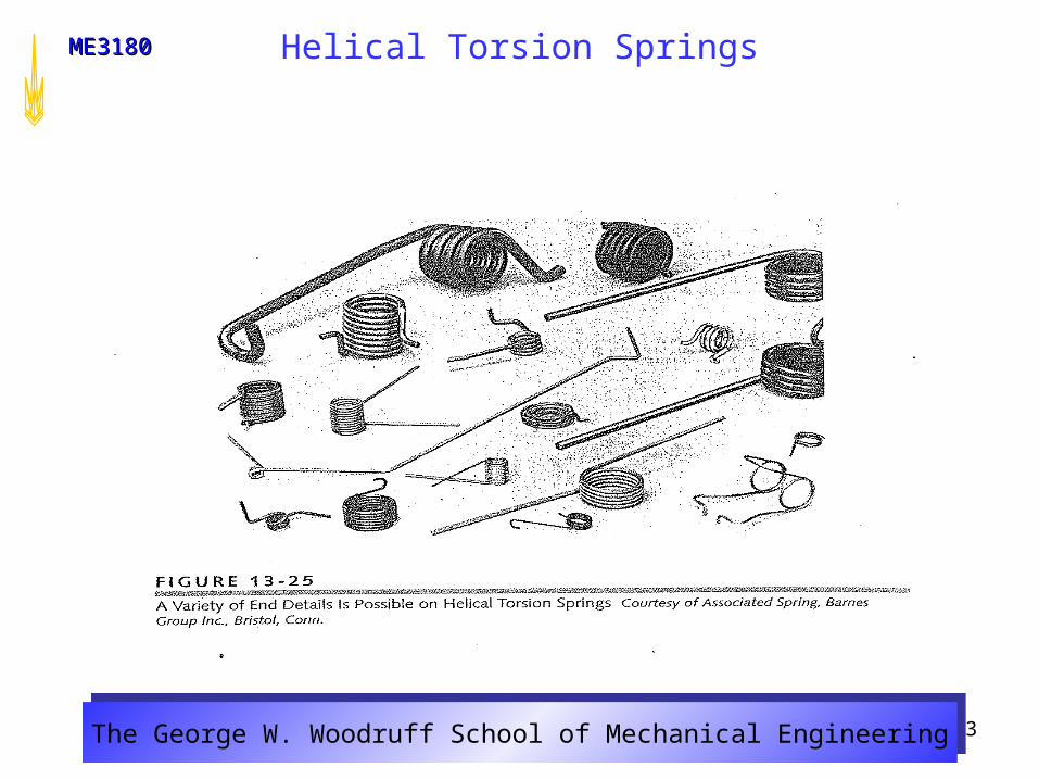
Ends come in variety of shapes to suit application
Coils are close wound like extension springs (but do not have any initial tension), but in few cases are wound with spacing like compression spring (this will avoid friction between coils)
Applied moment should always be arranged to close coils rather than open them because residual stresses from coil-winding are favorable against a closing moment (i.e., residual stresses oppose working stresses).
The George W. Woodruff School of Mechanical EngineeringThe George W. Woodruff School of Mechanical Engineering
ME3180ME3180
3
Helical Torsion Springs
The George W. Woodruff School of Mechanical EngineeringThe George W. Woodruff School of Mechanical Engineering
ME3180ME3180
4
Helical Torsion Springs – Cont’d
Dynamic loading should be repeated or fluctuating with stress ratio R 0
Applied moment should never be reversed in service
Normal stresses are produced in torsion springs
Load should be defined at angle between tangent ends in loaded
position rather than at deflection from free position
Rectangular wire is more efficient (because load is in bending) in terms of
stiffness per unit volume (larger I for same dimension)
However, most helical torsion springs are made from round wire
because of its lower cost and larger variety of available sizes and materials
Torsion springs are used in door hinges, rat traps, automobile starters,
finger exercisers, garage doors and etc

The George W. Woodruff School of Mechanical EngineeringThe George W. Woodruff School of Mechanical Engineering
ME3180ME3180
5
Helical Torsion Springs – Cont’d
Number of Coils in Torsion SpringsFor straight ends, the contribution to equation 13.26b can be expressed as an equivalent number of coils Ne:
Active coils:
Where Nb is number of coils in spring body
DeflectionAngular deflections of coil-end is normally expressed in radians, but is often converted to revolutions. Revolutions will be used.
D
LLNe 3
21
eba NNN
EI
MLwradrev 2
1θ
2
1θ
(13.26a)
(13.26b)
(13.27a)
The George W. Woodruff School of Mechanical EngineeringThe George W. Woodruff School of Mechanical Engineering
ME3180ME3180
6
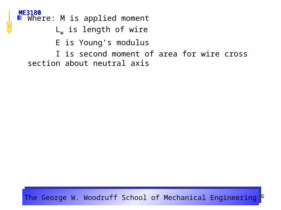
Where: M is applied moment
Lw is length of wire
E is Young’s modulus
I is second moment of area for wire cross section about neutral axis
The George W. Woodruff School of Mechanical EngineeringThe George W. Woodruff School of Mechanical Engineering
ME3180ME3180
7
Helical Torsion Springs – Cont’d
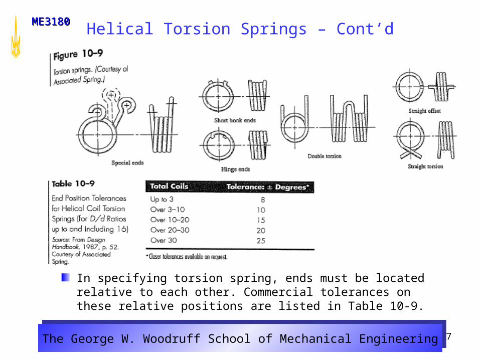
In specifying torsion spring, ends must be located relative to each other. Commercial tolerances on these relative positions are listed in Table 10-9.
The George W. Woodruff School of Mechanical EngineeringThe George W. Woodruff School of Mechanical Engineering
ME3180ME3180
8
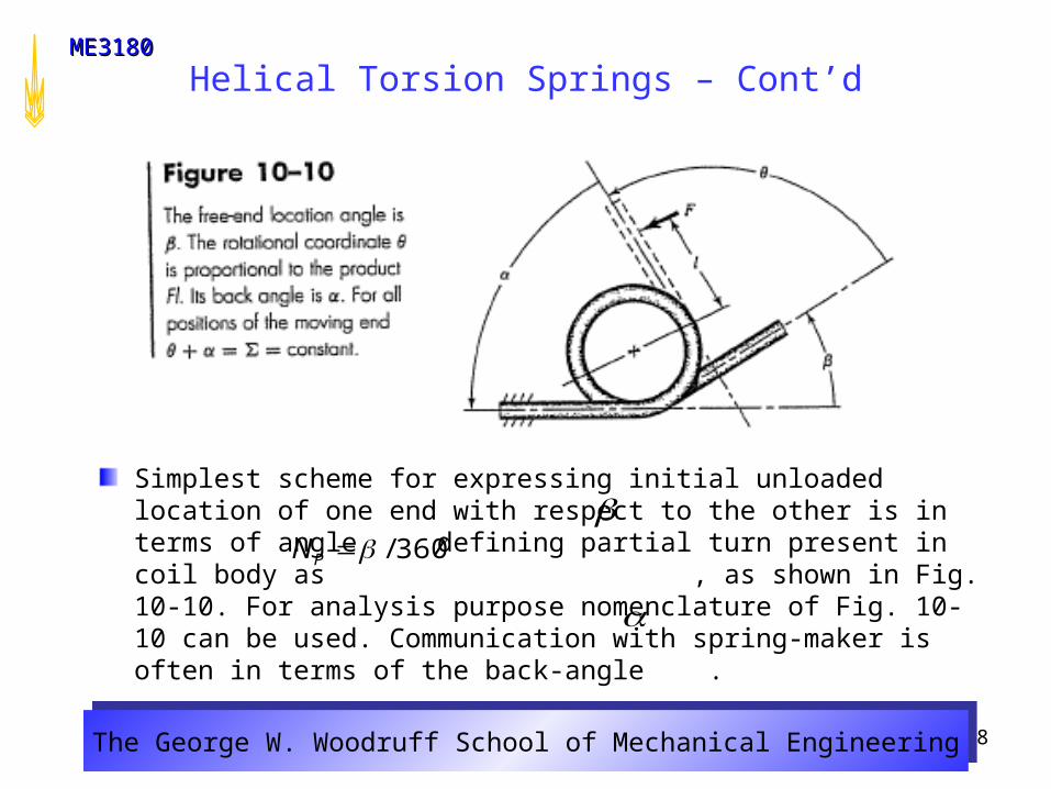
Simplest scheme for expressing initial unloaded location of one end with respect to the other is in terms of angle defining partial turn present in coil body as , as shown in Fig. 10-10. For analysis purpose nomenclature of Fig. 10-10 can be used. Communication with spring-maker is often in terms of the back-angle .
Helical Torsion Springs – Cont’d
360/PN
The George W. Woodruff School of Mechanical EngineeringThe George W. Woodruff School of Mechanical Engineering
ME3180ME3180
9
Helical Torsion Springs – Cont’d
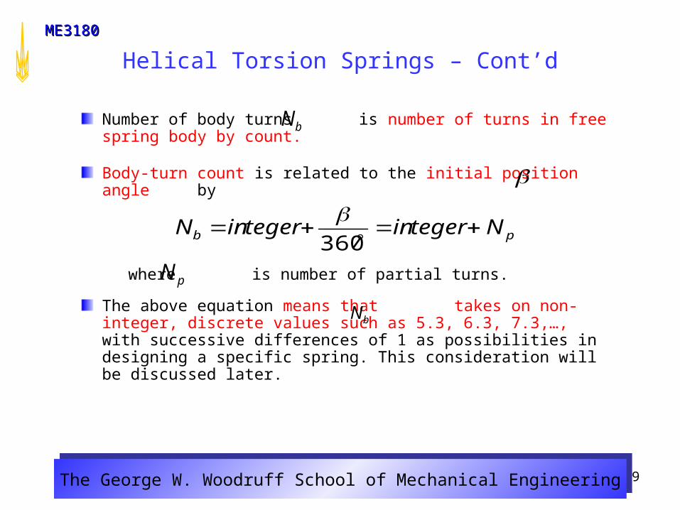
Number of body turns is number of turns in free spring body by count.
Body-turn count is related to the initial position angle by
where is number of partial turns.
The above equation means that takes on non-integer, discrete values such as 5.3, 6.3, 7.3,…, with successive differences of 1 as possibilities in designing a specific spring. This consideration will be discussed later.
bN
pb NtegerintegerinN
360
pN
bN
The George W. Woodruff School of Mechanical EngineeringThe George W. Woodruff School of Mechanical Engineering
ME3180ME3180
10
Helical Torsion Springs – Cont’d
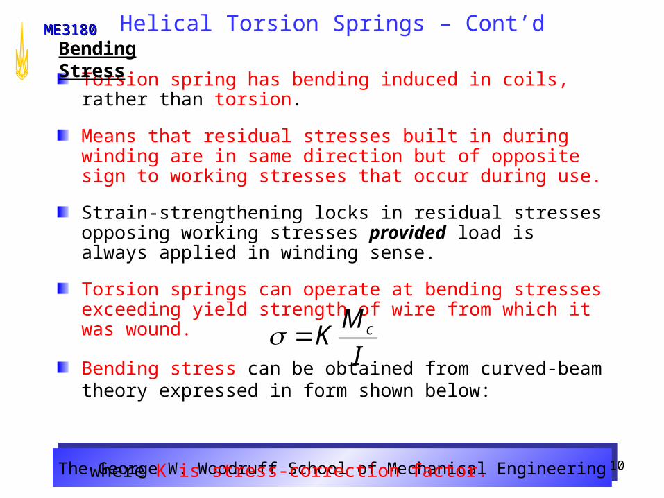
Torsion spring has bending induced in coils, rather than torsion.
Means that residual stresses built in during winding are in same direction but of opposite sign to working stresses that occur during use.
Strain-strengthening locks in residual stresses opposing working stresses provided load is always applied in winding sense.
Torsion springs can operate at bending stresses exceeding yield strength of wire from which it was wound.
Bending stress can be obtained from curved-beam theory expressed in form shown below:
where K is stress-correction factor.
Bending Stress
I
MK c

The George W. Woodruff School of Mechanical EngineeringThe George W. Woodruff School of Mechanical Engineering
ME3180ME3180
11
Helical Torsion Springs – Cont’d
Value of K depends on shape of wire cross section and whether stress is sought at inner or outer fiber. Wahl analytically determined values of K to be, for round wire,
where C is spring index and subscript i and o refer to inner and outer fibers, respectively.
In view of fact that Ko is always less than unity, we shall use K i to estimate the stresses. When bending moment is M = Fr and section modulus , we express bending equations as
which gives the bending stress for a round-wire torsion spring.
(10-43)
(10-44)
)1(4
14 2
CC
CCK i
)1(4
14 2
CC
CCKo
32// 3dCI
3
32
d
FrK i
The George W. Woodruff School of Mechanical EngineeringThe George W. Woodruff School of Mechanical Engineering
ME3180ME3180
12
Helical Torsion Springs – Cont’d
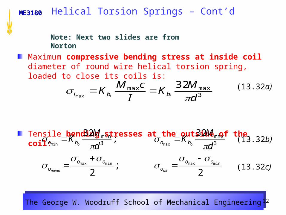
Maximum compressive bending stress at inside coil diameter of round wire helical torsion spring, loaded to close its coils is:
Tensile bending stresses at the outside of the coil:
2;
2
32;
32
minmaxminmax
maxmin 3max
3min
ooo
ooo
bobo
altmean
oo d
MK
d
MK
(13.32b)
(13.32c)
3maxmax 32
max d
MK
I
cMK
ii bbi (13.32a)
Note: Next two slides are from Norton
The George W. Woodruff School of Mechanical EngineeringThe George W. Woodruff School of Mechanical Engineering
ME3180ME3180
13
Helical Torsion Spring - Cont’d
For static failure (yielding) of torsion spring loaded to close its coils, compressive stress σimax at inside of coil is of most concern
For fatigue failure, which is a tensile-state phenomenon σomax at outside of coils is of concern
Alternating and mean stresses are calculated at outside of coil
Since closely spaced coils prevent shot from impacting inside diameter of coil, shot peening may not be effective in torsion springs
The George W. Woodruff School of Mechanical EngineeringThe George W. Woodruff School of Mechanical Engineering
ME3180ME3180
14
Helical Torsion Springs – Cont’d
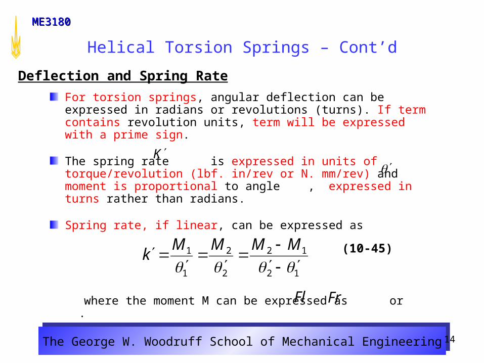
For torsion springs, angular deflection can be expressed in radians or revolutions (turns). If term contains revolution units, term will be expressed with a prime sign.
The spring rate is expressed in units of torque/revolution (lbf. in/rev or N. mm/rev) and moment is proportional to angle , expressed in turns rather than radians.
Spring rate, if linear, can be expressed as
where the moment M can be expressed as or .
Deflection and Spring Rate
(10-45)
K
12
12
2
2
1
1
MMMM
k
FrFl
The George W. Woodruff School of Mechanical EngineeringThe George W. Woodruff School of Mechanical Engineering
ME3180ME3180
15
Helical Torsion Springs – Cont’d
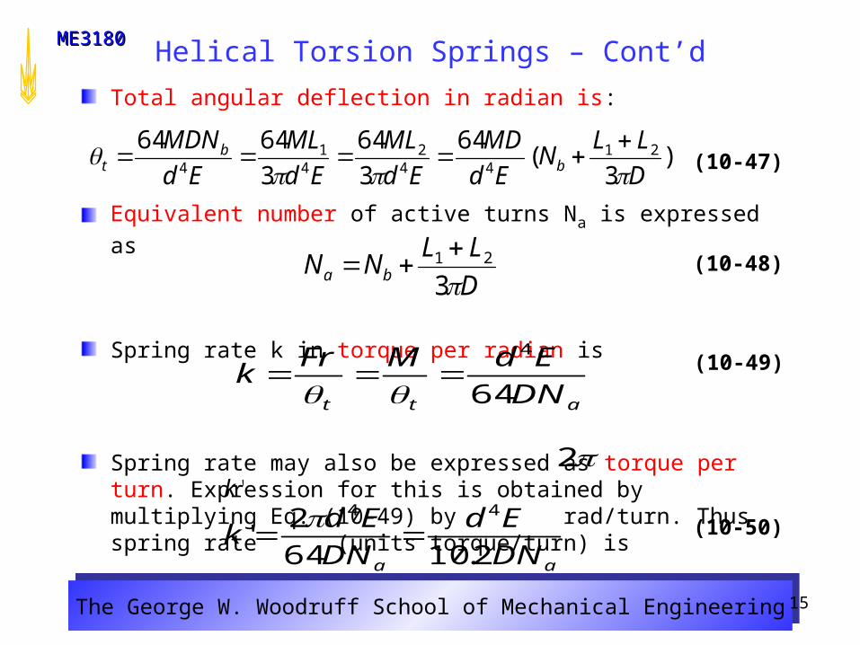
Total angular deflection in radian is:
Equivalent number of active turns Na is expressed as
Spring rate k in torque per radian is
Spring rate may also be expressed as torque per turn. Expression for this is obtained by multiplying Eq. (10-49) by rad/turn. Thus spring rate (units torque/turn) is
(10-47)
(10-48)
aa DN
Ed
DN
Edk
2.1064
2'
44
(10-49)
'k
att DN
EdMFrk
64
4
(10-50)
)3
(64
3
64
3
6464 2144
24
14 D
LLN
Ed
MD
Ed
ML
Ed
ML
Ed
MDNb
bt
D
LLNN ba 3
21
2
The George W. Woodruff School of Mechanical EngineeringThe George W. Woodruff School of Mechanical Engineering
ME3180ME3180
16
Helical Torsion Springs – Cont’d
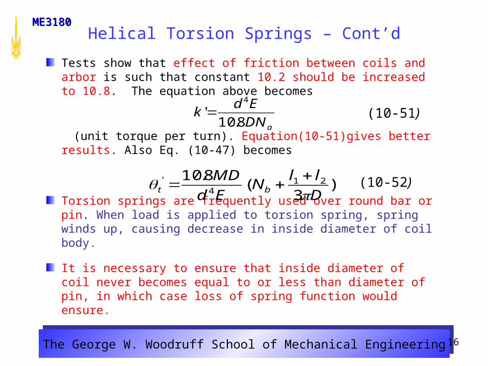
Tests show that effect of friction between coils and arbor is such that constant 10.2 should be increased to 10.8. The equation above becomes
(unit torque per turn). Equation(10-51)gives better results. Also Eq. (10-47) becomes
Torsion springs are frequently used over round bar or pin. When load is applied to torsion spring, spring winds up, causing decrease in inside diameter of coil body.
It is necessary to ensure that inside diameter of coil never becomes equal to or less than diameter of pin, in which case loss of spring function would ensure.
aDN
Edk
8.10'
4
(10-51)
)3
(8.10 214
'
D
llN
Ed
MDbt
(10-52)
The George W. Woodruff School of Mechanical EngineeringThe George W. Woodruff School of Mechanical Engineering
ME3180ME3180
17
Helical Torsion Springs – Cont’d
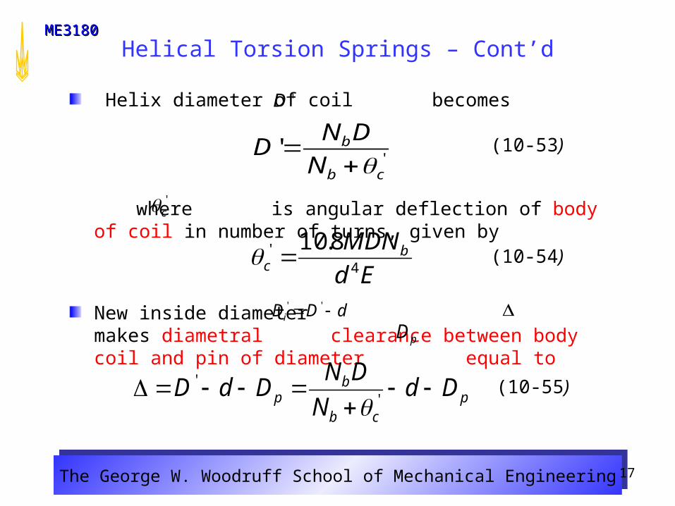
Helix diameter of coil becomes
where is angular deflection of body of coil in number of turns, given by
New inside diameter makes diametral clearance between body coil and pin of diameter equal to
Ed
MDNbc 4' 8.10
'D
(10-53)
'c
''
cb
b
N
DND
(10-54)
pcb
bp Dd
N
DNDdD
''
pD
dDDi ''
(10-55)
The George W. Woodruff School of Mechanical EngineeringThe George W. Woodruff School of Mechanical Engineering
ME3180ME3180
18
Helical Torsion Springs – Cont’d
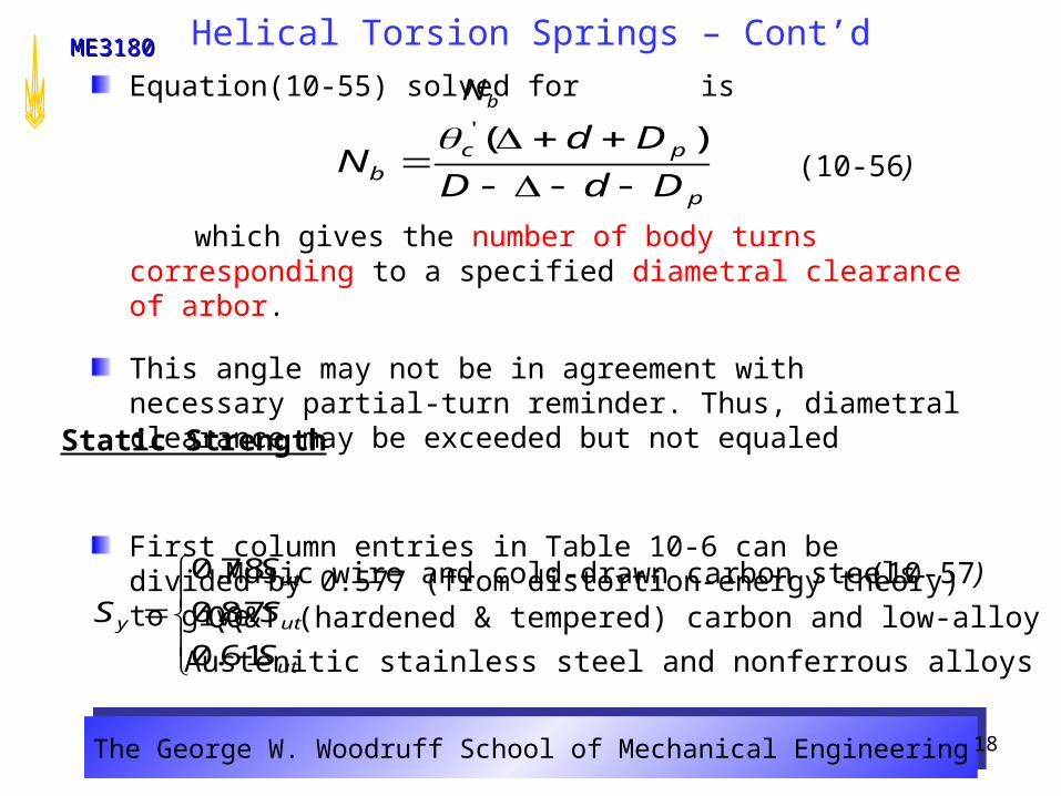
Equation(10-55) solved for is
which gives the number of body turns corresponding to a specified diametral clearance of arbor.
This angle may not be in agreement with necessary partial-turn reminder. Thus, diametral clearance may be exceeded but not equaled
First column entries in Table 10-6 can be divided by 0.577 (from distortion-energy theory) to give
bN
p
pcb DdD
DdN
)('
(10-56)
Static Strength
ut
ut
ut
y
S
S
S
S
61.0
87.0
78.0 (10-57)Music wire and cold-drawn carbon steels
QQ&T (hardened & tempered) carbon and low-alloy steels
Austenitic stainless steel and nonferrous alloys
The George W. Woodruff School of Mechanical EngineeringThe George W. Woodruff School of Mechanical Engineering
ME3180ME3180
19
Helical Torsion Springs – Cont’d

The George W. Woodruff School of Mechanical EngineeringThe George W. Woodruff School of Mechanical Engineering
ME3180ME3180
20
Helical Torsion Springs – Cont’d
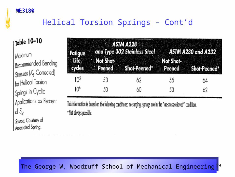
Since spring wire is in bending, Sines equation is not applicable. The Sines model is in the presence of pure torsion. Since Zimmerli’s results were for compression springs (wire in pure torsion), we will use the repeated bending stress (R = 0) values provided by Associated Spring in Table 10-10.
As in Eq. (10-40) we will use the Gerber fatigue-failure criterion incorporating the Associated Spring R = 0 fatigue strength :
Value of (and ) has been corrected for size, surface condition, and type of loading, but not for temperature or miscellaneous effects.
Fatigue Strength
2)2/
(1
2/
ut
r
re
SS
SS
rS
rS eS
(10-58)
The George W. Woodruff School of Mechanical EngineeringThe George W. Woodruff School of Mechanical Engineering
ME3180ME3180
21
Helical Torsion Springs – Cont’d
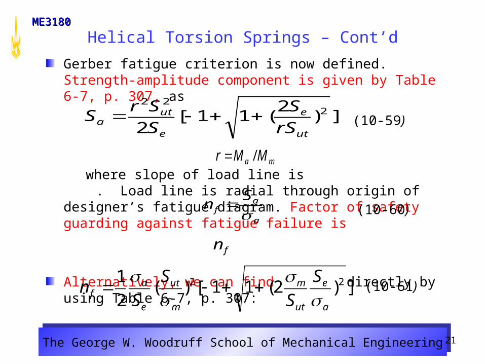
Gerber fatigue criterion is now defined. Strength-amplitude component is given by Table 6-7, p. 307, as
where slope of load line is . Load line is radial through origin of designer’s fatigue diagram. Factor of safety guarding against fatigue failure is
Alternatively, we can find directly by using Table 6-7, p. 307:
])2(11[)(2
1 22
a
e
ut
m
m
ut
e
af
S
S
S
Sn
(10-59)
ma MMr /
fn
(10-60)a
af
Sn
])2
(11[2
222
ut
e
e
uta rS
S
S
SrS
(10-61)


![Ondulé: Designing and Controlling 3D Printable Springs · HELICAL SPRING THEORY Our approach is based on helical springs [22], which have three basic configurations—compression,](https://img.pdfslide.us/doc/110x75/5e97e6d886fa3e4f6f1a5e42/ondul-designing-and-controlling-3d-printable-helical-spring-theory-our-approach.jpg)


![UNIT-III TORSION AND SPRINGS PART-A [2-MARKS]](https://img.pdfslide.us/doc/110x75/61d91b3769f57355f90a2c3d/unit-iii-torsion-and-springs-part-a-2-marks.jpg)