Embed Size (px)
Citation preview

ORNL/SPR-2015/257
Update on ORNL TRANSFORM Tool: Simulating Multi-Module Advanced Reactor with End-to-End I&C
David L. Fugate M. Sacit Cetiner Richard E. Hale A. Lou Qualls
May 2015
Approved for public release. Distribution is unlimited.

DOCUMENT AVAILABILITY
Reports produced after January 1, 1996, are generally available free via US Department of Energy (DOE) SciTech Connect. Website http://www.osti.gov/scitech/ Reports produced before January 1, 1996, may be purchased by members of the public from the following source: National Technical Information Service 5285 Port Royal Road Springfield, VA 22161 Telephone 703-605-6000 (1-800-553-6847) TDD 703-487-4639 Fax 703-605-6900 E-mail [email protected] Website http://www.ntis.gov/help/ordermethods.aspx Reports are available to DOE employees, DOE contractors, Energy Technology Data Exchange representatives, and International Nuclear Information System representatives from the following source: Office of Scientific and Technical Information PO Box 62 Oak Ridge, TN 37831 Telephone 865-576-8401 Fax 865-576-5728 E-mail [email protected] Website http://www.osti.gov/contact.html
This report was prepared as an account of work sponsored by an agency of the United States Government. Neither the United States Government nor any agency thereof, nor any of their employees, makes any warranty, express or implied, or assumes any legal liability or responsibility for the accuracy, completeness, or usefulness of any information, apparatus, product, or process disclosed, or represents that its use would not infringe privately owned rights. Reference herein to any specific commercial product, process, or service by trade name, trademark, manufacturer, or otherwise, does not necessarily constitute or imply its endorsement, recommendation, or favoring by the United States Government or any agency thereof. The views and opinions of authors expressed herein do not necessarily state or reflect those of the United States Government or any agency thereof.

ORNL/SPR-2015/257
Reactor and Nuclear Systems Division
Electrical and Electronics Systems Research Division
UPDATE ON ORNL TRANSFORM TOOL: SIMULATING MULTI-MODULE ADVANCED
REACTOR WITH END-TO-END I&C
David L. Fugate
M. Sacit Cetiner
Richard E. Hale
A. Lou Qualls
Date Published: May 2015
Prepared by
OAK RIDGE NATIONAL LABORATORY
Oak Ridge, TN 37831-6283
managed by
UT-BATTELLE, LLC
for the
US DEPARTMENT OF ENERGY
under contract DE-AC05-00OR22725


iii
CONTENTS
Page
LIST OF FIGURES ...................................................................................................................................... v ACRONYMS .............................................................................................................................................. vii ACKNOWLEDGMENTS ........................................................................................................................... ix EXECUTIVE SUMMARY ......................................................................................................................... xi 1. INTRODUCTION ................................................................................................................................ 1
1.1 BACKGROUND ........................................................................................................................ 1 2. MODULAR DYNAMIC SIMULATION TOOL ................................................................................. 3
2.1 PREVIOUS WORK .................................................................................................................... 3 2.2 END-TO-END REACTOR POWER PLANT MODEL ............................................................. 3 2.3 END-TO-END REACTOR POWER PLANT MODEL WITH I&C ......................................... 6 2.4 NEW UPDATED STEAM GENERATOR MODEL ................................................................. 6 2.5 CONTROL OF THE NEW UPDATED STEAM GENERATOR MODEL ............................ 11 2.6 NEW UPDATED STEAM GENERATOR MODEL CONCLUSIONS .................................. 24
3. MULTI-MODULE REACTOR CONFIGURATION ........................................................................ 25 4. CONCLUSIONS ................................................................................................................................ 31 5. REFERENCES ................................................................................................................................... 33


v
LIST OF FIGURES
Figure Page
Fig. 1. Modular architecture for the advanced liquid metal reactor end-to-end system model. .................... 4 Fig. 2. Top-level architecture of the small modular advanced high-temperature reactor dynamic
simulation tool for electricity generation. ................................................................................. 5 Fig. 3. Steam generation secondary site diagram .......................................................................................... 8 Fig. 4. Updated steam generator model. ....................................................................................................... 9 Fig. 5. Updated steam generator model user configurations. ...................................................................... 10 Fig. 6. Updated steam generator model details. .......................................................................................... 11 Fig. 7. Steam generator drum model details with instrumentation (see areas labeled #1–6). ..................... 12 Fig. 8. Steam generator drum model with instrumentation (see areas labeled #1–4). ................................ 13 Fig. 9. Steam generator instrumentation ..................................................................................................... 14 Fig. 10. An open loop simulation. Holding the sodium, recirculation, and steam flow constant, the
feedwater flow was perturbed. ................................................................................................ 15 Fig. 11. An open loop simulation. Holding the sodium, feedwater, and steam flow constant, the
recirculation flow was perturbed. ............................................................................................ 15 Fig. 12. An open loop simulation. Holding the feedwater, recirculation, and steam flow constant,
the sodium flow was perturbed................................................................................................ 16 Fig. 13. Open loop simulation results, showing transfer function approximation and pole zero maps. ..... 17 Fig. 14. Control formulation of water level control based on level error. .................................................. 18 Fig. 15. Water level control based on level error with water level setpoint change. .................................. 19 Fig. 16. Water level control based on level error with recirculation flow disturbance. .............................. 19 Fig. 17. Water level control based on level error with recirculation flow disturbance. .............................. 20 Fig. 18. Water level control based on level error with sodium flow disturbance. ...................................... 20 Fig. 19. Water level control based on level error with steam pressure disturbance. ................................... 21 Fig. 20. Control formulation of water level control based on level error and flow error. ........................... 21 Fig. 21. Water level control based on level error with sodium flow disturbance. ...................................... 22 Fig. 22. Water level control based on level error with steam pressure disturbance. ................................... 22 Fig. 23. Closed loop simulation results, showing transfer function approximation and pole zero
maps. ....................................................................................................................................... 23 Fig. 24. PRISM example interfaces among a single reactor module, intermediate heat exchangers,
and the steam generator ........................................................................................................... 25 Fig. 25. PRISM example of other components between the IHXs and the steam generator ...................... 26 Fig. 26. ALMR PRISM PHTS implementation with two reactor modules. ............................................... 27 Fig. 27. ALMR PRISM IHX implementation with two IHXs. ................................................................... 27 Fig. 28. TRANSFORM top-level diagram for two reactor examples. ........................................................ 28 Fig. 29. TRANSFORM top-level diagram for two reactor examples shows an average channel
temperature profile for both reactors. ...................................................................................... 29

vii
ACRONYMS
ALMR advanced liquid-metal reactor
ART Advanced Reactor Technology
I&C instrumentation and controls
IHX intermediate heat exchanger
IHTS intermediate heat transport system
PCS power conversion system
PHTS primary heat transport system
PRISM power reactor innovative small module
SMR small modular reactor
TRANSFORM Transient Simulation Framework of Reconfigurable Models


ix
ACKNOWLEDGMENTS
The research described in this report was sponsored by the Advanced Reactor Technology (formerly
Advanced Reactor Concept) Program of the US Department of Energy Office of Nuclear Energy.


xi
EXECUTIVE SUMMARY
The Small Modular Reactor (SMR) Dynamic System Modeling Tool project is in the fourth year of
development. The project is designed to support collaborative modeling and study of various advanced
SMR (non-light water cooled reactor) concepts, including the use of multiple coupled reactors at a single
site.
Previous deliverables focused on the development of component and system models as well as end-to-end
system models using Modelica and Dymola for two advanced reactor architectures: (1) advanced liquid
metal reactor and (2) fluoride high temperature reactor. The focus of this deliverable is the development
of a steam generator and drum system model that includes the complex dynamics of typical steam drum
systems, the development of instrumentation and controls for the steam generator with drum system
model, and the development of multi-reactor module models that reflect the full power reactor innovative
small module design concept discussed in detail in previous deliverables [1–3].
In 2015, the project has transitioned from the Advanced SMRs Research and Development Program to the
Advanced Reactors Technology (ART) Program that is designed to promote safety, technical, economic,
and environmental advancements of innovative Generation IV nuclear energy technologies. The objective
of the project, however, remains the same: to provide a common simulation environment and baseline
modeling resources to facilitate rapid development of dynamic advanced reactor models; ensure
consistency among research products within the Instrumentation, Controls, and Human-Machine Interface
technical area; and leverage cross-cutting capabilities while minimizing duplication of effort that often
exists if multiple programs develop separate models independently.
The combined simulation environment and suite of models are identified as the TRANSFORM tool. The
critical elements of this effort include (1) defining a standardized, common simulation environment that
can be applied throughout the ART program; (2) developing a library of baseline component modules that
can be assembled into full plant models using available geometry, design, and thermal-hydraulic data; (3)
defining modeling conventions for interconnecting component models; and (4) establishing user
interfaces and support tools to facilitate simulation development (i.e., configuration and
parameterization), execution, and results display and capture.
In addition to steam generator control, additional control features are needed to complete the end-to-end
system control. In particular, the main steam turbine valve and the feedwater heater system have controls
that need to be modeled. These control elements will be further developed in the final deliverable for
fiscal year 2015.
The end result of these efforts is the development of a set of streamlined tools and models that can be
used throughout the ART program. This report documents the accomplishment of this goal and lays the
foundation for use of this tool among multiple projects.


1
1. INTRODUCTION
1.1 BACKGROUND
As documented previously [1–3], the intent of this project is to develop simulation resources and tools to
allow a collaborative modeling and control study for various advanced (non-light water reactor), small
modular reactor (SMR) configurations. The project has been funded under the Advanced SMR Program
and is in the fourth and final year of development. This project, however, is currently being transitioned to
the Advanced Reactor Technology (ART) Program with less emphasis on SMRs and more emphasis on
advanced reactor concepts. Therefore, any further development will be transitioned to the ART Program’s
priorities.
High-level objectives of this effort include the following: (1) develop a steam generator and drum system
model that reflects designs that are more commonly deployed in modern power generation plants; (2)
develop appropriate instrumentation and controls (I&C) for the updated steam generator model to
facilitate I&C studies for advanced reactor concepts; and (3) develop multi-reactor module models for
simulations, I&C, and hybrid energy systems studies. These objectives have been met and are
documented in this report. The purpose of this report is to document the progress in meeting the described
objectives. The complex dynamics of the steam generator and drum system are demonstrated with water
level shrink and swell behavior. The development of I&C follows industry practices and demonstrates the
challenges of the steam generator and drum system for control stability. The development of the multi-
reactor module supports end-to-end power plant models that reflect the power reactor innovative small
module (PRISM) design concepts.


3
2. MODULAR DYNAMIC SIMULATION TOOL
2.1 PREVIOUS WORK
Documented previous work [1, 2] defines a flexible modeling architecture and structure using Dymola
and Modelica to support the modeling of various advanced reactor power plant concepts, such as the
advanced liquid metal reactor (ALMR) and the fluoride high temperature reactor. This modeling
architecture and structure is the Transient Simulation Framework of Reconfigurable Models
(TRANSFORM) tool, which supports the selection and simulation of different power plant configurations
and components, including different I&C configurations.
2.2 END-TO-END REACTOR POWER PLANT MODEL
The development of an end-to-end power plant model using the TRANSFORM tool is documented [2].
Power generating plants with different reactor types maintain the same basic elements of thermal energy
generation, thermal energy conversion to electricity, cooling, and I&C. The TRANSFORM end-to-end
power plant model includes the following subsystems as the minimum set:
(1) Primary heat transport system
(2) Intermediate heat exchanger
(3) Intermediate heat transport system
(4) Steam generator
(5) Power conversion system (PCS)
(6) Grid
Additional subsystems may include the following:
(1) Instrumentation and controls
(2) Event driver
(3) Safety systems
Figure 1 is an example of the TRANSFORM architecture for the ALMR power generation plant model.
Figure 1 illustrates various power plant subsystems that are organized in the Modelica environment as
different classes. The use of Modelica classes supports the ability to select different variations of a
subsystem within common interconnections with the other subsystem classes. For example, in the
Dymola environment, a user may select different configurations of the primary heat transport system
(PHTS) for a desired purpose, but all of these variations will interact with the other local subsystem
models. Figure 2 illustrates the system with the addition of the event drive and supervisory control
subsystems.
The PHTS baseline model class includes dynamic modeling of the reactor material effects, core, fuel pins,
kinetics, heat transfer, and core cooling flow with axial profile distributions [2, 3]. Also included is the
primary heat transport cooling system interaction with the intermediate heat exchanger (IHX). The model
supports user selection of the number of axial and radial nodes, fuel assemblies, fuel pins per assembly,
and other settings related to the coolant channel, reactor kinetics, and primary cooling loop.
The IHX serves as the thermal and flow interface between the PHTS and the IHTS. The current base
model class IHX consists of a heat exchanger model using a tube and shell configuration with axial nodes,
and it uses one-dimensional flow elements. This configuration is based on the ALMR PRISM concept.
The working fluids for the primary and secondary side are sodium [4].

4
Fig. 1. Modular architecture for the advanced liquid metal reactor end-to-end system model.
(Note: DRACS = Direct Reactor Auxiliary Cooling System.)

Fig. 2. Top-level architecture of the small modular advanced high-temperature reactor dynamic simulation tool for electricity generation.

6
The IHTS transfers thermal energy from IHX to the steam generator subsystem. The IHTS baseline model
class is based on the PRISM concept but uses only one IHTS module rather than the two modules used in
the PRISM concept. The IHTS demonstrates dynamic behavior and time-lag for thermal differentials
between PHTS and the steam generator. The piping span lengths are user selectable and will reflect length
changes with fluid dynamics and delays [3]. IHTS is primarily a fluid pump and transport system.
The baseline TRANSFORM steam generator [3] is based on a once-pass-through heat exchanger design.
This currently modeled steam generator configuration is a vertically oriented tube and shell design with
sodium on the shell side and water and steam on the tube side. The model consists of two flow channels
that are thermally coupled for steam generation.
The power conversion system (PCS) is the interface between the steam generator and the electric grid
subsystems. The baseline TRANSFORM model classes include an implementation that has a simple
steam separator with a two-stage turbine to create rotational mechanical energy for the grid model. The
electric grid TRANSFORM model class includes the electric synchronous generator, external
transmission grid, frequency and power measurements, and a disconnect breaker.
The I&C TRANSFORM model class uses the control bus interface to access various subsystem
measurements and actuation devices. This enables the selection of various measurements as control
inputs, various actuation devices as control outputs, and the development of a variety of control
approaches for the different subsystems [3].
The event driver TRANSFORM model class is an interface to the rest of the power plant model that
enables the insertion of disturbances or transient conditions into the desired subsystem for simulation
purposes. The event driver can access and manipulate various subsystem devices using the control bus.
Examples of events such as reactivity disturbances are simulated with different control strategies in Ref.
3. The safety systems TRANSFORM model class includes implementations based on the reactor vessel
auxiliary cooling system and direct reactor auxiliary cooling system [2].
2.3 END-TO-END REACTOR POWER PLANT MODEL WITH I&C
Modules for I&C overlays and event drivers have been developed for the models discussed in Sect. 2.2
following the chosen flexible modeling architecture [1–3]. These models with I&C demonstrated the
ability to adjust the power plant model to changing power outputs while maintaining proper temperatures,
flows, and pressures in the power plant [1–3]. Previous work with I&C development included control of
the PHTS reactor power output using the control rod position, PHTS reactor core outlet temperature using
the PHTS fluid temperature, IHTS fluid temperature using the IHTS cooling pump, and PCS electric
power generation by adjusting the steam flow to the turbine. Two different control strategy approaches
were developed with control based upon a desired temperature or the temperature difference of key power
plant temperatures [3].
2.4 NEW UPDATED STEAM GENERATOR MODEL
The main purpose of the steam generator is to convert water to dry saturated steam, which is used to
convert thermal energy into mechanical energy in the steam turbine. Other purposes include the ability to
act as a heat sink during normal and abnormal conditions, to provide short-duration thermal energy
storage, and to act as a barrier between the thermal energy source and the PCS. These purposes require
both a heat exchanger and a containment vessel to provide the heat sink and thermal energy storage
functions. In many power plants, this is performed with a vertical shell and U-tube heat exchanger in a
storage vessel that contains both water and steam. An example of a steam generator system with steam
drum is shown in Fig. 3. This example illustrates the hot and cold leg outlet at the bottom that is the fluid
path for the thermal energy source. The lower-to-middle sections contain the heat exchanger. The
feedwater inflow nozzle introduces turbine exhaust condensate water below the steam separators to
7
maintain the proper water level. Recirculation collects the water drainage from the steam separators. The
steam separators and steam dryers process the dry steam for outflow into the steam outlet to the turbine.
The dynamics of the steam generator with steam drum can be complex. At steady state, the steam is
maintained at some pressure in the drum. Changes to steam consumption by the turbine control valve will
change the steam pressure. For example, if the steam flow increases, the steam drum pressure will
decrease. A decrease in pressure will cause more hot water to flash into steam and increase the water level
for a short duration before the water level returns to a lower level equilibrium. This short-term effect is
called swell. If the steam flow decreases, a reverse phenomenon called shrink will occur. Decreases in
steam flow will cause the pressure to rise, which causes the steam bubbles to collapse and reduce the
water level for a short duration before the water level returns to a higher level equilibrium [5].
The short-duration energy storage ability of the steam generator permits different control modes. The
boiler following mode or constant pressure mode consists of using the turbine steam governor control
valve as a fast acting controller with the steam generator control reacting with a slower response to
maintain constant pressure. The short-duration stored energy permits the turbine to increase power output
for fast changing load demands. The sliding pressure mode consists of using a variable steam pressure
setpoint to provide better turbine efficiency at lower power outputs. This enables operation of the turbine
at lower temperatures and pressures [6].
The once-pass-through heat exchanger design steam generator model described in Sect. 2.2 addresses the
basic function of heat exchange to generate steam and uses some of the PRISM design concepts but does
not provide heat sink or short-duration storage features. This heat exchange model is a closed water
system that does not includes containment vessel effects for water level, recirculation, and feedwater
functionality but does include effects for heat transfer with boiling. Steam generators without water
containment are best suited to turbine following mode control, which consists of setting the steam
generator to a fixed or very slowly changing output value and performing small adjustments to the turbine
control valve. Base load power generation would consist of the steam generator being set to a fixed
maximum output and the turbine control valve set to full open.

8
Fig. 3. Steam generation secondary site diagram [5].
In the TRANSFORM SMR concepts library, a new updated steam generator has been developed that
includes the dynamics of drum containment for water and steam and is based on the design in Fig. 3. The
equations for the mass and energy balances for the liquid and vapor phases must describe the mass,
internal energy, volume, pressure, thermal energy, mass flow rate, and enthalpy of the drum system [8, 9].
The updated steam generator model with drum is implemented to include the state variables: steam
pressure, water volume, steam quality, steam volume, liquid and vapor enthalpy, and metal wall
temperature. This approach will include nonlinearities, dynamics of shrink and swell, and the highly
efficient heat transfer of boiling and condensation under pressure. The system of water, vapor, and
equipment is at thermal equilibrium. Energy stored in the water and steam can be released or absorbed
very quickly because of pressure changes [9].
This updated model in Dymola is shown in Figs. 4–6. Figure 4 illustrates the vessel with the hot leg inlet
(left side) and cold leg outlet (lower right side), which makes up the fluid path for the thermal energy
source. The steam outlet is at the top. The feedwater input is on the upper right. The lower-to-middle
sections contain the heat exchanger. The feedwater inflow nozzle introduces the turbine exhaust
condensate with the water below the steam separators to maintain the proper water level. The
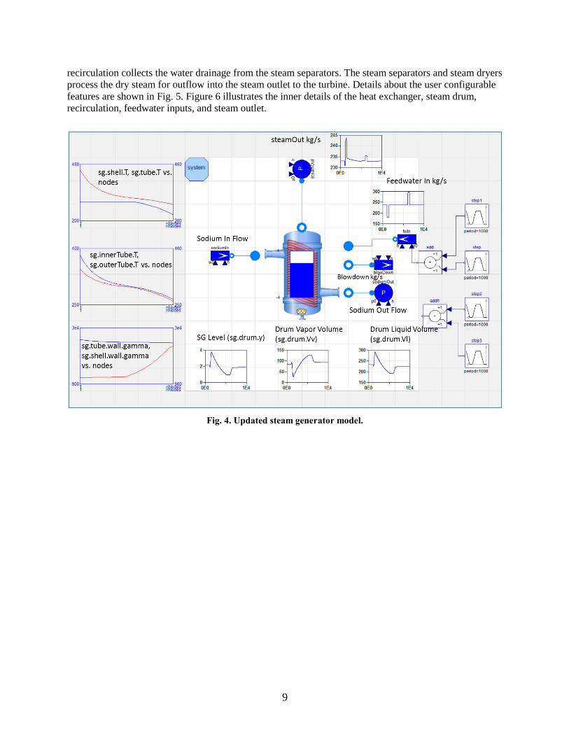
9
recirculation collects the water drainage from the steam separators. The steam separators and steam dryers
process the dry steam for outflow into the steam outlet to the turbine. Details about the user configurable
features are shown in Fig. 5. Figure 6 illustrates the inner details of the heat exchanger, steam drum,
recirculation, feedwater inputs, and steam outlet.
Fig. 4. Updated steam generator model.

10
Fig. 5. Updated steam generator model user configurations.

11
Fig. 6. Updated steam generator model details.
2.5 CONTROL OF THE NEW UPDATED STEAM GENERATOR MODEL
The new steam generator with drum model discussed in Sect. 2.2 was modified to add I&C features. First
instrumentation was added to the steam drum model to measure water level, steam pressure, sodium inlet
pressure, sodium inlet flow, recirculation flow, and recirculation pressure (Fig. 7). Instrumentation also
was added to the steam drum external model for the feedwater flow, steam flow, steam outlet
temperature, and sodium inlet temperature (Fig. 8) [5–7].
In some power plants, the water level is measured by up to 10 level transmitters that monitor different
ranges with a variety of sensitivity levels. Figure 9 is an example of steam generator instrumentation.
Some level transmitters are used by the safety system for generator and turbine trip events. Steam
generator pressure transmitters monitor if the pressure drops below desired operating conditions to avoid
instabilities [5].
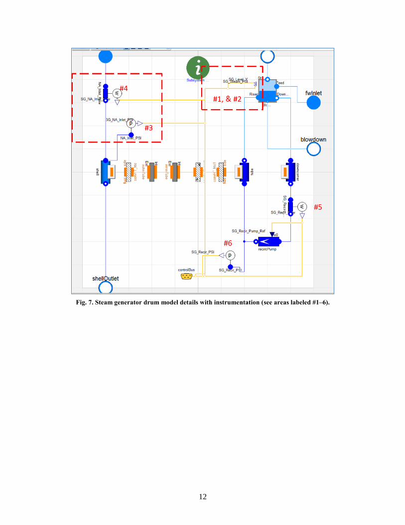
12
Fig. 7. Steam generator drum model details with instrumentation (see areas labeled #1–6).

13
Fig. 8. Steam generator drum model with instrumentation (see areas labeled #1–4).

14
Fig. 9. Steam generator instrumentation [5].
The new steam generator model with drum dynamics was simulated for the following open loop test cases
shown in Figs. 10–12:
(1) Holding the sodium, recirculation, and steam flow constant, the feedwater flow was perturbed
briefly.
(2) Holding the sodium, feedwater, and steam flow constant, the recirculation flow was perturbed
briefly.
(3) Holding the recirculation, feedwater, and steam flow constant, the sodium flow was perturbed
briefly.
Figure 10 illustrates that a brief change in the feedwater flow causes the water level to raise or lower in an
opposite manner from the feedwater change (steam generator water level in plot #2 in Fig. 10), which is
due to the swell/shrink phenomenon discussed in Sect. 2.2. The results show the water level initially
follows the feedwater flow reduction by a reduction in the water level, then the water level swells for a
short duration and finally settles to a reduced water level value. Changes to the steam generator drum
feedwater flow can cause the water level to demonstrate non-minimum phase behavior for short durations
[6]. The steam mass flow (steam generator steam outlet mass flow in plot #10 in Fig. 10) indicates that
the steam mass flow is closely correlated to the water level.
Figure 11 illustrates that a brief change in the recirculation flow directly drives the water level in the
proper direction with no significant change in the steam flow. Figure 12 illustrates that a brief change in
the sodium flow drives the water level up in a sustained manner and causes a similar brief but significant
change in the steam flow.

15
Fig. 8. An open loop simulation. Holding the sodium, recirculation, and steam flow constant, the feedwater
flow was perturbed.
Fig. 9. An open loop simulation. Holding the sodium, feedwater, and steam flow constant, the recirculation
flow was perturbed.

16
Fig. 10. An open loop simulation. Holding the feedwater, recirculation, and steam flow constant, the sodium
flow was perturbed.
Data from these open-loop tests were examined using the Matlab System Identification Toolbox. Transfer
function approximations of the water level response to changes in the feedwater, recirculation, and
sodium flows revealed dynamic system poles of ~-12 and ~0 with a system zero of ~+0.1 (Figure 13).
The positive system zero verifies the non-minimum phase behavior of the water level due to shrink and
swell effects.
The steam generator will provide the heat exchange and the desired ability to provide an energy sink and
storage if the proper volume of water is maintained by a suitable level control. Just as the steam flow is
varied, the feedwater flow must be varied to maintain the suitable net mass resident in the system. If the
resident water volume is held constant, then the recirculation flow can be held constant.

17
Fig. 11. Open loop simulation results, showing transfer function approximation and pole zero maps.
The first step in developing a proper level control system is to target controlling the level directly using
the level feedback measurement and actuating the feedwater flow input.1 The non-minimum phase
behavior previously noted will require consideration to avoid the feedback control reacting improperly to
this behavior. To compensate for the water level behavior, a first order lag feature will be used to dampen
the short-term shrink and swell behavior of the raw water level measurement. The lag was configured for
a time constant of 2 minutes based on projected time constants [9]. Then the feedwater flow input was
added to the control bus to provide control access. A proportional plus integral control was selected to
adjust the feedwater flow to provide the desired water level. Because of the noted water level behavior, a
discrete time integrator with a 2 minute update rate was selected to reduce the control sensitivity to shrink
and swell behavior [6, 7]. A block diagram and the equations for this control formulation are shown in
Fig. 14. This control loop approach demonstrated the ability to control the water level as desired with
constant recirculation, sodium flow, and steam flow. Figure 15 illustrates how the water level behavior is
stable and does not demonstrate non-minimum phase behavior for water level setpoint changes. The water
level approaches the modified setpoint while demonstrating over-damped behavior without overshoot or
oscillation.
The steam drum level control also must perform during changes in steam, sodium, and recirculation flow.
Simulations with recirculation flow disturbances were examined. Figures 16 and 17 illustrate that
recirculation flow disturbance of different durations does disturb the water level by ~1%, and the
feedwater flow is adjusted by the control to bring the water level back to the setpoint.
Next, the effect of sodium flow disturbances was examined. Figure 18 demonstrates that a short duration
sodium flow disturbance initially causes the water level to depart significantly from the setpoint. Then the
feedwater level error control and sodium disturbance causes the water level to depart drastically from the
setpoint range and oscillate over a large range until it settles near the setpoint. This is undesirable
behavior.
1 Details of tool use are contained in the User’s Manual documented in previous reports [1–3].

18
Figure 19 illustrates the water level response with a short duration steam pressure disturbance. The water
level significantly shifts above the setpoint for the duration of the steam pressure disturbance. After the
steam flow disturbance, the water level error control overcompensates, and the level is lowered
significantly below the setpoint. Much later, it settles near the setpoint. This is undesirable behavior.
The results in Figs. 15–19 demonstrated that the water level error control performed suitably for
conditions with constant sodium and steam flows. This approach did not perform appropriately for
changes in sodium or steam flows. This led to the addition of another control mode based on the concept
of matching the feedwater flow to the steam flow. These two mass flows must be maintained for the
proper energy balance in the system. Figure 20 illustrates the block diagram and equation of the new
control approach that combines the water level error control and a flow error control [5–7].
The sodium flow disturbance that was examined in Fig. 18 is illustrated with the updated control
approach in Fig. 21. The water level is disturbed ~25% and settles back to the setpoint without any
oscillation of overshoot, which is a tremendous improvement over the results in Fig. 18. The steam
pressure disturbance that was examined in Fig. 18 is illustrated in the updated control approach in Fig. 22.
The peak water level disturbance value is similar to the water level error control, but the duration of the
excursion is reduced ~50% and the following oscillation amplitude is reduced ~50% with the water level
settling back to the water level setpoint.
Data from the updated control approach were examined using the Matlab System Identification Toolbox.
Transfer function approximations of the closed-loop water level response show that the dynamic system
open-loop poles of ~-12 and ~0 with a system zero of ~+0.1 have now changed to system pole values of
two poles at ~-4.8 10-5
with the system zero value of ~-9.5 10-5 (Fig. 23). The positive system zero is
now negative, which removes the non-minimum phase behavior observed in the open-loop response. The
addition of the lag on the water level feedback with the discrete time integrator had the effect of moving
the pole of ~-12 to near the origin like a pure integrator. The system now demonstrates high stability
margins.
Fig. 12. Control formulation of water level control based on level error.

19
Fig. 13. Water level control based on level error with water level setpoint change.
Fig. 14. Water level control based on level error with recirculation flow disturbance.

20
Fig. 15. Water level control based on level error with recirculation flow disturbance.
Fig. 16. Water level control based on level error with sodium flow disturbance.

21
Fig. 17. Water level control based on level error with steam pressure disturbance.
Fig. 18. Control formulation of water level control based on level error and flow error.

22
Fig. 19. Water level control based on level error with sodium flow disturbance.
Fig. 20. Water level control based on level error with steam pressure disturbance.

23
Fig. 21. Closed loop simulation results, showing transfer function approximation and pole zero maps.

24
2.6 NEW UPDATED STEAM GENERATOR MODEL CONCLUSIONS
A new steam generator with drum model was introduced in Sect. 2.4, and I&C capabilities were added to
the model in Sect. 2.5. This new steam generator model includes effects such as water level shrink and
swell and energy storage, which led to limited instabilities in the water level for some conditions. The
I&C capabilities included the addition of instrumentation for level, pressure, flow, and temperature.
Control features were also added to enable the evaluation of two control strategies. The I&C approach
was based on industry legacy knowledge for similar power plants and led to a stable water level control
system for all typical conditions. This new steam generator model with I&C later will be incorporated
into an updated end-to-end power plant model. This will facilitate the ability to observe the interaction of
the turbine with the steam generator and the steam generator with the other balance of plant systems.

25
3. MULTI-MODULE REACTOR CONFIGURATION
The TRANSFORM SMR concepts library offers a flexible architecture that can be modified significantly
at the subsystem level without any need for modification at the top end-to-end system level. Previously,
Oak Ridge National Laboratory demonstrated the use of TRANSFORM with a single reactor module
coupled to a turbine/generator system [1–3]. However, the baseline ALMR PRISM design employs three
power blocks, each with three reactor modules, which drive a single turbine/generator. Figures 24 and 25
show how these subsystems are linked; that linkage causes dynamic coupling.
Fig. 22. PRISM example interfaces among a single reactor module, intermediate heat exchangers, and the
steam generator [4].

26
Fig. 23. PRISM example of other components between the IHXs and the steam generator [4].
In this reporting cycle, TRANSFORM includes PHTS implementations with a single reactor module and
additional two-reactor modules. The difference in the single module implementation is that all of the
PHTS components are bundled in a module. The two-reactor module implementation employs two
instances of the same reactor module object (i.e., R 1 and R 2), as shown in Fig. 26. The
specifications of each reactor module can be defined individually. In other words, the module instances
use the same model but can operate with different parameters, configurations, and settings. This would
allow the two modules to have differing power generation levels, fidelity, or other characteristics. The
state variables and initialization for each reactor module are independent during the simulation.
This implementation of the PHTS subsystem uses vectorized fluid interfaces that are dynamically sized
based on the number of modules defined. The use of the vectorized fluid interfaces enables the desired
degree of flexibility and configurability. To match the ALMR PRISM system specification—that is, each
reactor module having two IHX—the IHX subsystem was also modified, as shown in Fig. 27. In this
implementation, each IHX object is a class vector that is instantiated based on the number of modules
defined in the PHTS. As an example, because this version includes a two-module implementation, there
are four IHXs in the IHX subsystem block.
The top-level system architecture is modified based on the new two-reactor capabilities added to
TRANSFORM as shown in Fig. 28. Because there are two modules within PHTS, it is possible to trace
the dynamics of individual reactor models during a simulation. As seen in Fig. 29, temperature profile of
each reactor module (i.e., R 1 and R 2) differs by ~20 degrees because of different power level inputs
per module. Although the total power delivered to PCS can be maintained, it is possible to run modules at
different power levels if the inlet/outlet temperatures and the temperature differentials across cores match.
This requires an active multiple input/multiple output control system regulating the module-level
operation based on the input requirements of the PCS.

27
Fig. 24. ALMR PRISM PHTS implementation with two reactor modules.
Fig. 25. ALMR PRISM IHX implementation with two IHXs.

28
Fig. 26. TRANSFORM top-level diagram for two reactor examples.

29
Fig. 27. TRANSFORM top-level diagram for two reactor examples shows an average channel temperature
profile for both reactors.


31
4. CONCLUSIONS
The objective of the project is to provide a common simulation environment and establish baseline
modeling resources to facilitate rapid development of dynamic advanced reactor models. The
TRANSFORM tool provides this environment as well as the initial models to begin populating a library
for advanced reactor I&C. The result of these efforts has been the development of a set of streamlined
tools and models that can be used throughout the ART program. This report documents the
accomplishment of this goal and lays the foundation for the use of this tool among multiple projects. The
tools and models are beginning to be used within the ART program (supervisory control) as well as part
of other programs within the US Department of Energy (hybrid energy systems). This report, the next to
last deliverable scheduled for FY 2015, documents additional I&C controls being incorporated within the
TRANSFORM PRISM model.
The remaining work identified for FY 2015 includes initial development of high temperature gas cooled
reactor component models as well as finalizing I&C control for the main steam turbine valve and the
feedwater heater. Finally, preliminary efforts towards establishing baseline validation and verification of
models to be included in the library will be addressed. Efforts to continue incorporating this tool into
other ART projects will continue.


33
5. REFERENCES
1. Update on Small Modular Reactors Dynamic System Modeling Tool—Web Application, ORNL/SPR-2015/17, Oak Ridge National Laboratory, Oak Ridge, Tenn., January 2015.
2. Update On Small Modular Reactors Dynamic System Modeling Tool—Molten Salt Cooled
Architecture, ORNL/TM-2014/322, Oak Ridge National Laboratory, Oak Ridge, Tenn., August
2014.
3. Update on Small Modular Reactors Dynamic System Modeling Tool, ORNL/TM-2014/50, Oak
Ridge National Laboratory, Oak Ridge, Tenn., March 2014.
4. Prism Preliminary Safety Information Document, GEFR-00793, UC-87TA, General Electric
Advanced Nuclear Technology, San Jose, Calif., December 1987.
5. USNRC HRTD, Steam Generator, Rev. 10/08.
6. D. Flynn, ed., Thermal Power Plant Simulation and Control (Institute of Electrical Engineers,
2003). ISBN 0 85296 419 6.
7. Westinghouse Technology Systems, “Westinghouse Technology Systems Manual, Section 11.1,
Steam Generator Water Level Control System,” 0519–R304P.
http://pbadupws.nrc.gov/docs/ML1122/ML11223A293.pdf.
8. F. Casella and A. Leva, “Modelica Open Library for Power Plant Simulation: Design and
Experimental Validation,” Proceedings of the Third International Modelica Conference, 2003, p.
41–50.
9. K. J. Astrom and R. D. Bell, “Drum-boiler Dynamics,” Automatica 36, No. 3 (2000): 363–378.