Embed Size (px)
Citation preview
PROPORTIONAL CONTROLS
H
No.1
Pub. EC-1302
Up to 24.5 MPa (3550 PSI), 400 L /m in (106 U.S.GPM)
E SERIES PROPORTIONAL PRESSURE CONTROLS
Pilot Relief / Relief / Reducing and Relieving
Pilot Relief Valves ................................................. Page 4
Relief Valves .......................................................... Page 11
Reducing and Relieving Valves ........................... Page 21
Proportional pressure control valves control the system pressure proportionally through a controlled input current from the amplifier. Therefore, the continuous and stepless pressure control can be obtained even with a single valve. the valves are of help not only to simplify the system design but also to eliminate any shocks in the hydraulic system.
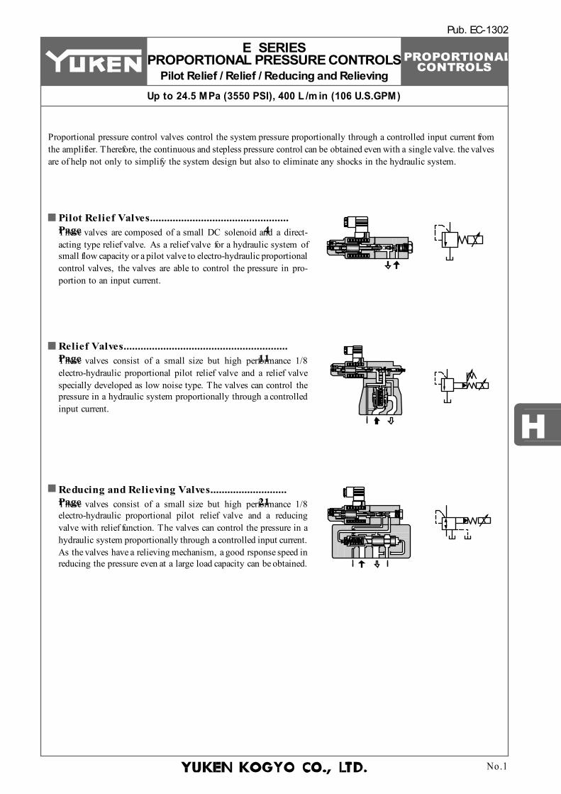
These valves are composed of a small DC solenoid and a direct-acting type relief valve. As a relief valve for a hydraulic system of small flow capacity or a pilot valve to electro-hydraulic proportional control valves, the valves are able to control the pressure in pro-portion to an input current.
These valves consist of a small size but high performance 1/8 electro-hydraulic proportional pilot relief valve and a relief valve specially developed as low noise type. The valves can control the pressure in a hydraulic system proportionally through a controlled input current.
These valves consist of a small size but high performance 1/8 electro-hydraulic proportional pilot relief valve and a reducing valve with relief function. The valves can control the pressure in a hydraulic system proportionally through a controlled input current. As the valves have a relieving mechanism, a good rsponse speed in reducing the pressure even at a large load capacity can be obtained.
PROPORTIONAL CONTROLS
Hydraulic Fluids
Petroleum Base Oils
Synthetic Fluids
Water-containing Fluids
Use fluids equivalent to ISO VG 32 or VG 46.Use phosphate ester or polyol ester fluids. When phosphate ester fluid is used, prefix "F-" to the model number because the special seals (fluororubber) are required to be used.Use water-glycol fluid.
Pilot Relief Valves Relief Valves Reducing and Relieving Valves
Name Viscosity Temperature2 15 - 400 mm /s
(77 - 1800 SSU)-15 - +70°C (5 - 160°F)
Hydraulic FluidsFluid TypesAny type of hydraulic fluid listed in the table below can be used.
Note:For use with hy draulic fluids other than those listed above, please consult y our Yuken representatives in advance.
Recommended Fluid Viscosity and TemperatureUse hydraulic fluids which satisfy the both recommended viscosity and oil temperatures given in the table below.
Control of ContaminationDue caution must be paid to maintaining control over contamination of the hydraulic fluids which may otherwise lead to breakdowns and shorten the life of the valve. Please maintain the degree of contamination within NAS 1638-Grade 11. Use 20 µm or finer line filter.
No.2
E SERIES PRESSURE CONTROL VALVES
Pilot Relief / Relief / Reducing and Relieving
PROPORTIONAL CONTROLS
H
Instructions
Air Vent
SOLS
OL
Air Vent
Air Vent
SO
L
10 Series Solenoid
Solenoid
Air Vent 3 Places
Manual Pressure Adj. Screw
Ω
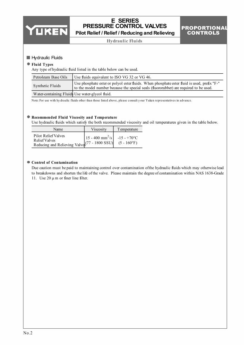
MountingBe sure that the air vent faces up. In addition, if the valve is mounted vertically, the minimum adjustment pressure is 2 MPa (290 PSI) or higher.
E SERIES PRESSURE CONTROL VALVES
Pilot Relief / Relief / Reducing and Relieving
No.3
[Good ex ample] [Bad ex ample]
Air BleedingTo ensure stable control, bleed the air from solenoid completely and fill its core with oil. Bleeding can be done by slowly loosening one of the air vents at the end of the solenoid. Choose one of the three air vents which is expected to work most effectively (see the figure to the right).
Manual Adjustment ScrewWhen initial adjustments are to be made or when no current is supplied to the valve due to electrical failure or other problem, turn the manual pressure adjustment screw to temporarily set the valve pressure. In that case, when turn the manual pressure adjustment screw clockwise, the valve pressure rises. Under normal condition, however, this screw must be kept in its original position (see the figure to the right).
Tank and Drain PipingThe tank-line back pressure and drain back pressure directly affect the minimum adjustment pressure. Therefore, do not connect the tank or drain pipes to other lines, but connect them directly to the reservoir maintaining the back pressure as low as possible. Be sure that the tank and drain pipe ends are immersed in fluid.
Hysteresis and Repeatability Value IndicationsThe hysteresis and repeatability values indicated in the specifications for each control valve are determined under the following conditions:
Hysteresis Value: Repeatability Value:
Obtained when Yuken's applicable power amplifier is used. Obtained when Yuken's applicable power amplifier is used under the same conditions.
PROPORTIONAL CONTROLS
2
3
1
1. 2. 3.
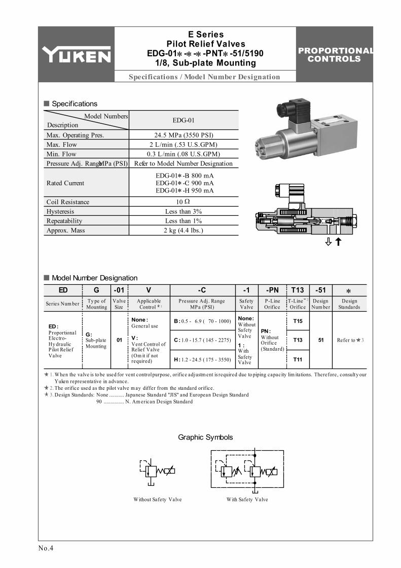
Specifications / Model Number Designation
Model Numbers EDG-01DescriptionMax. Operating Pres. Max. Flow Min. Flow Pressure Adj. Range
24.5 MPa (3550 PSI) 2 L/min (.53 U.S.GPM)
0.3 L/min (.08 U.S.GPM) Refer to Model Number Designation
Ω
Proportional Electro- Hy draulic P ilot Relief Valve
ED:
EDSeries Num ber
GTy pe of
Mounting
-01 V -C -1 -PN T13
Sub-plate Mounting
G:01
Valve Size
Applicable Control
General useNone :
Vent Control of Relief Valve (Om it if not required)
V : C: 1.0 - 15.7 ( 145 - 2275)
Pressure Adj . Range MPa (PSI)
Safety Valve
W ithout Safety Valve
None:
W ith Safety Valve
1 :
P-Line Orifice
T-Line Orifice
W ithout Orifice (Standard)
PN:
Design Standards
T15
MPa (PSI)
Coil Resistance Hysteresis Repeatability Approx. Mass
10 Less than 3% Less than 1% 2 kg (4.4 lbs.)
Rated CurrentEDG-01∗-B EDG-01∗-C EDG-01∗-H
: 800 mA : 900 mA : 950 mA
B: 0.5 - 6.9 ( 70 - 1000)
H: 1.2 - 24.5 ( 175 - 3550)
T13
T11
-51Design
Num ber
51
∗
Refer to
W ith Safety Valve
Graphic Symbols
W ithout Safety Valve
Specifications
Model Number Designation
W hen the valve is to be used for vent control purpose, orifice adjustm ent is required due to piping capacity lim itations. Therefore, consult y our Yuken representative in advance. The orifice used as the pilot valve m ay differ from the standard orifice.
No.4
Design Standards: None 90
Japanese Standard "JIS" and European Design Standard N. Am erican Design Standard
........... ...............
E Series Pilot Relief Valves
EDG-01∗-∗-∗-PNT∗-51/5190 1/8, Sub-plate Mounting
PROPORTIONAL CONTROLS
Sub-plate / Instructions / Others
H
×
×
DSGM-01-3090 DSGM-01X-3090 DSGM-01Y-3090
1/8 NPT 1/4 NPT 3/8 NPT
0.8 (1.8) 0.8 (1.8) 0.8 (1.8)
P iping SizeJapanese Standard "JIS"Sub-plate
Model Num bers
European Design StandardSub-plate
Model Num bers
N. Am erican Design StandardSub-plate
Model Num bersThread
Size
Approx. MassThread
SizeThread
SizeDSGM-01-3080 DSGM-01X-3080
1/8 BSP.F 1/4 BSP.F
DSGM-01-30 DSGM-01X-30 DSGM-01Y-30
Rc 1/8 Rc 1/4 Rc 3/8
1/8 1/4 3/8
kg (lbs.)
L/min
U.S.GPM
Add
ition
al P
ress
ure
MPaPSI
.50
2
2.0300
Flow Rate
10
.250
1.0
0
225
150
75
0
E Series Pilot Relief Valves
EDG-01
Attachment
No.5
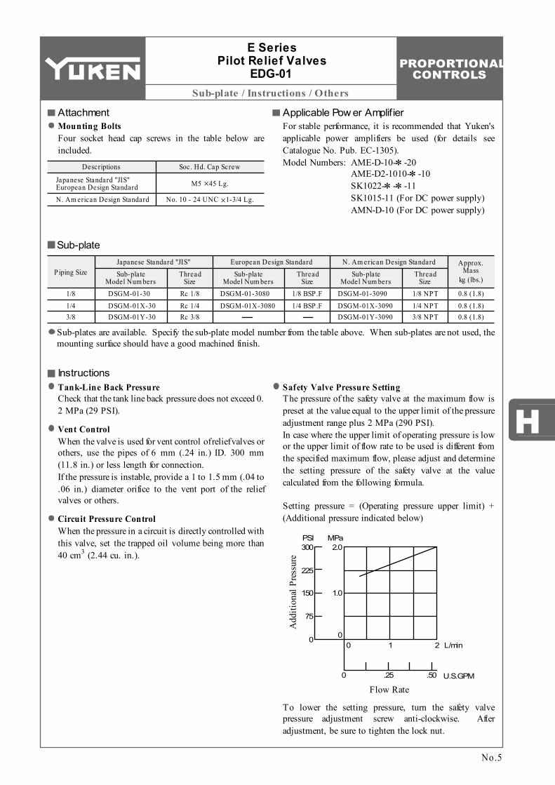
Mounting BoltsFour socket head cap screws in the table below are included.
Sub-plates are available. Specify the sub-plate model number from the table above. When sub-plates are not used, the mounting surface should have a good machined finish.
Sub-plate
Descriptions Soc. Hd. Cap Screw
Japanese Standard "JIS" European Design StandardN. Am erican Design Standard
M5 45 Lg.
No. 10 - 24 UNC 1-3/4 Lg.
Applicable Pow er AmplifierFor stable performance, it is recommended that Yuken's applicable power amplifiers be used (for details see Catalogue No. Pub. EC-1305).Model Numbers: AME-D-10-∗-20
AME-D2-1010-∗-10 SK1022-∗-∗-11 SK1015-11 (For DC power supply) AMN-D-10 (For DC power supply)
InstructionsTank-Line Back PressureCheck that the tank line back pressure does not exceed 0.2 MPa (29 PSI).
Vent ControlWhen the valve is used for vent control of relief valves or others, use the pipes of 6 mm (.24 in.) ID. 300 mm (11.8 in.) or less length for connection. If the pressure is instable, provide a 1 to 1.5 mm (.04 to .06 in.) diameter orifice to the vent port of the relief valves or others.
Circuit Pressure ControlWhen the pressure in a circuit is directly controlled with this valve, set the trapped oil volume being more than
3 40 cm (2.44 cu. in.).
Safety Valve Pressure SettingThe pressure of the safety valve at the maximum flow is preset at the value equal to the upper limit of the pressure adjustment range plus 2 MPa (290 PSI). In case where the upper limit of operating pressure is low or the upper limit of flow rate to be used is different from the specified maximum flow, please adjust and determine the setting pressure of the safety valve at the value calculated from the following formula. Setting pressure = (Operating pressure upper limit) + (Additional pressure indicated below)
To lower the setting pressure, turn the safety valve pressure adjustment screw anti-clockwise. After adjustment, be sure to tighten the lock nut.
PROPORTIONAL CONTROLS
Installation Drawing
Pressure Adj. Screw for
Safety Valve 3(.12) Hex.Soc.
INC.
52 (2.05)
Fully Extended216(8.50)Fully Extended
Lock Nut 10(.39) Hex.
40.5(1.59)
79(3.11)
20.5(.81)
0.75
(.03) 8.
5(.3
3)31
(1
.22)
32.5
(1
.28)
48
(1.8
9)
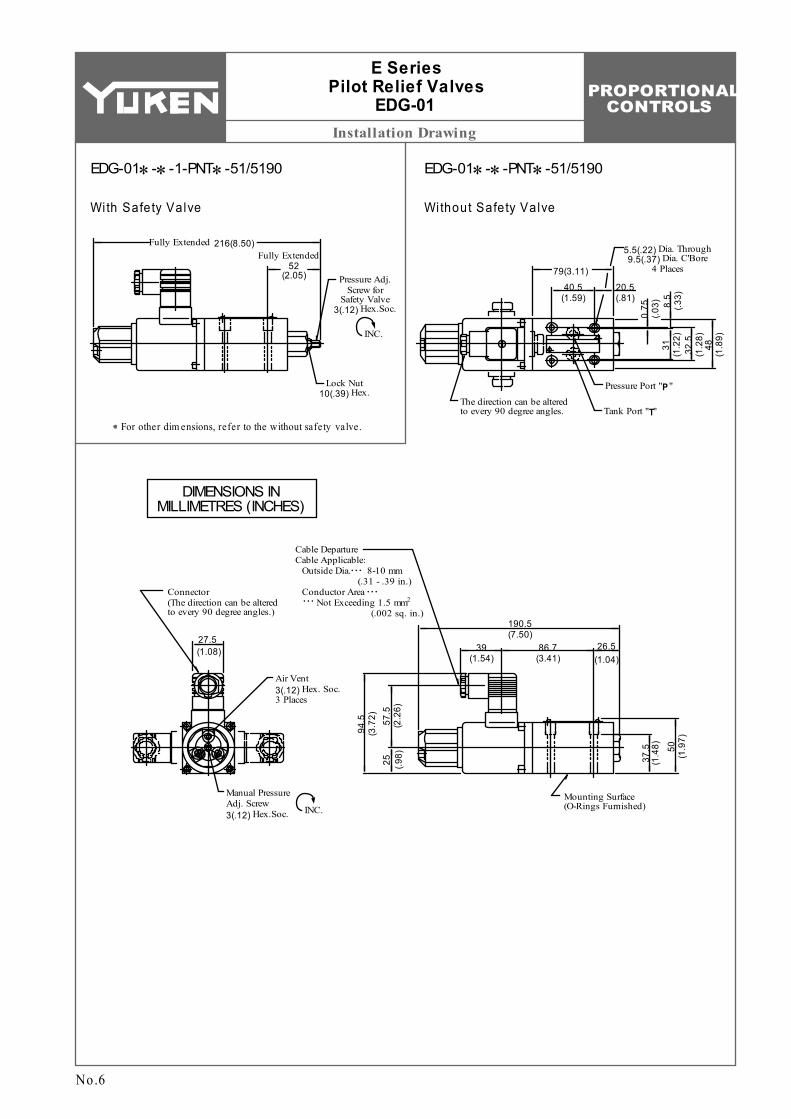
5.5(.22) Dia. Through 9.5(.37) Dia. C'Bore
4 Places
Pressure Port "P"
Tank Port "T"The direction can be altered to every 90 degree angles.
27.5(1.08)
Connector (The direction can be altered to every 90 degree angles.)
Cable Departure Cable Applicable: Outside Dia. 8-10 mm (.31 - .39 in.) Conductor Area
2 Not Exceeding 1.5 mm (.002 sq. in.)
. . .
. . .. . .
Manual Pressure Adj. Screw 3(.12) Hex.Soc. INC.
Mounting Surface (O-Rings Furnished)
50
(1.9
7)
37.5
(1
.48)
57.5
(2
.26)
94.5
(3
.72)
25
(.98)
39(1.54)
86.7(3.41)
26.5(1.04)
190.5(7.50)
Air Vent 3(.12) Hex. Soc. 3 Places
E Series Pilot Relief Valves
EDG-01
No.6
EDG-01∗-∗-1-PNT∗-51/5190
With Safety Valve
For other dim ensions, refer to the without safety valve.
EDG-01∗-∗-PNT∗-51/5190
Without Safety Valve
DIMENSIONS IN MILLIMETRES (INCHES)
PROPORTIONAL CONTROLS
H
Installation Drawing
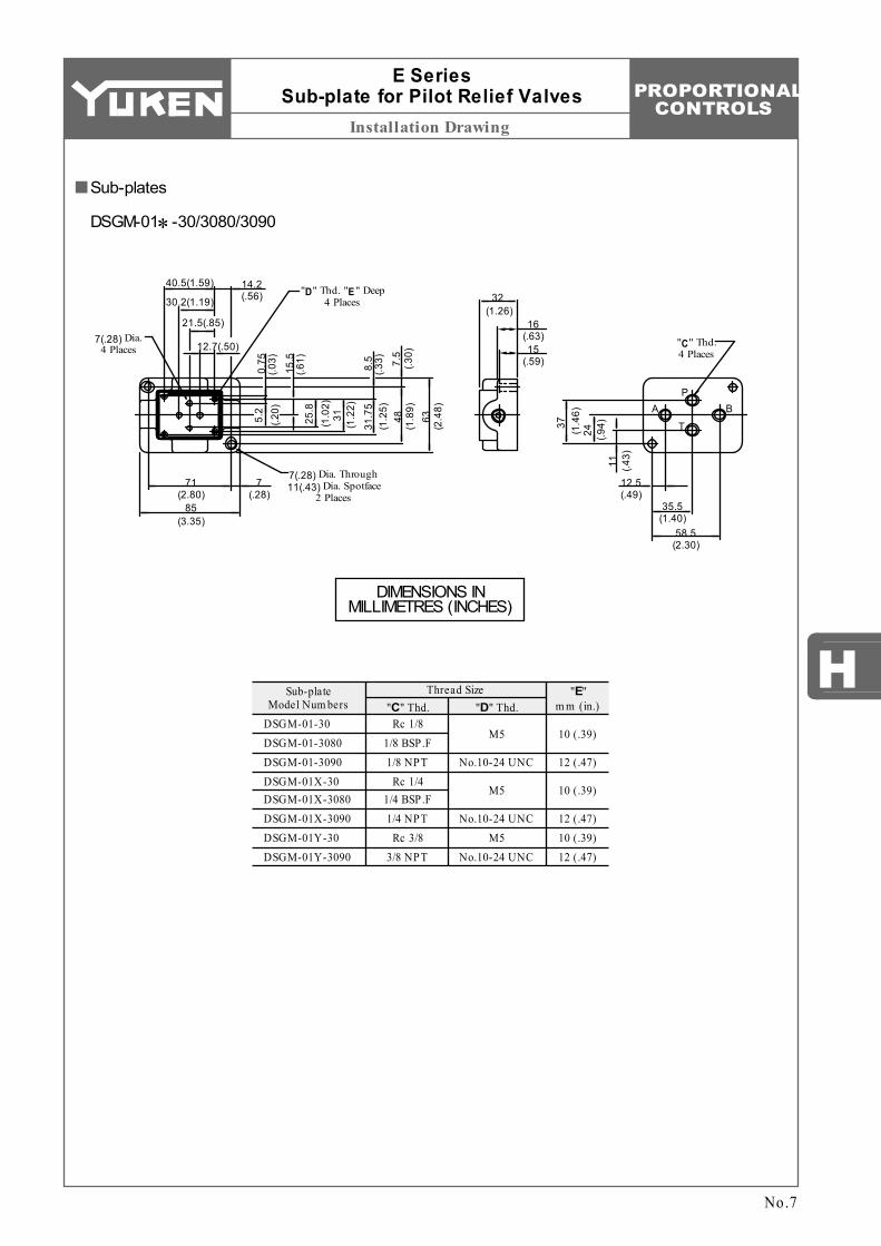
Sub-plate Model Num bers "C" Thd. "D" Thd.
"E" m m (in.)
M5
No.10-24 UNC
M5 No.10-24 UNC
M5
No.10-24 UNC10 (.39) 12 (.47)
10 (.39)
12 (.47)
10 (.39)
12 (.47)
DSGM-01-30 DSGM-01-3080 DSGM-01-3090 DSGM-01X-30 DSGM-01X-3080 DSGM-01X-3090 DSGM-01Y-30 DSGM-01Y-3090
Rc 1/8 1/8 BSP.F 1/8 NPT
Rc 1/4 1/4 BSP.F 1/4 NPT
Rc 3/8 3/8 NPT
Thread Size
A
T
PB
7(.28) Dia. 4 Places
"D" Thd. "E" Deep 4 Places
7(.28) Dia. Through 11(.43) Dia. Spotface
2 Places
14.2(.56)
12.7(.50)
21.5(.85)
30.2(1.19)
40.5(1.59)
7(.28)
71(2.80)
85(3.35)
5.2
(.20)
0.75
(.03)
15.5
(.61)
25.8
(1.0
2)31
(1.2
2)
31.7
5(1
.25)
8.5
(.33)
48(1
.89)
7.5
(.30)
63(2
.48)
15(.59)
16(.63)
32(1.26)
"C" Thd. 4 Places
12.5(.49)
35.5(1.40)
58.5(2.30)
11 (.43)
24 (.94)37 (1.4
6)
No.7
Sub-plates
DSGM-01∗-30/3080/3090
E Series Sub-plate for Pilot Relief Valves
DIMENSIONS IN MILLIMETRES (INCHES)
PROPORTIONAL CONTROLS
Typical Performance Characteristics
1200
MPaPSI
1000
800
600
400
200
PSI
1000
1500
2000
25002750
MPaEDG-01-B EDG-01-C
Pres
sure
Pres
sure
PSI
4000
MPa
Pres
sure3000
2000
1000
TimeTimeTime
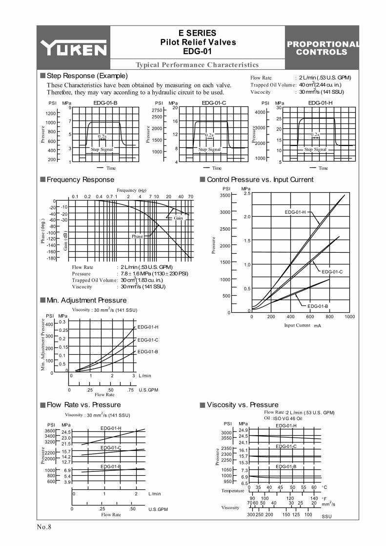
Flow Rate Trapped Oil Volum e Viscocity
: : :
2 L/min (.53 U.S. GPM) 3 40 cm (2.44 cu. in.) 2 30 mm /s (141 SSU)
EDG-01-H309
7
5
3
1
20
16
12
8
4
25
20
15
10
5
0.2s 0.2s 0.2s
Step Signal Step SignalStep Signal
-10-20-30
0-20-40-60-80
-100-120-140-160-180
0.1 0.2 0.4 0.7 1 2 4 7 10 20 40 70Frequency (Hz)
Gai
n (d
B)
Phas
e (d
eg.)
Flow Rate Pressure Trapped Oil Volum e Viscocity
: : : :
2 L/min (.53 U.S. GPM) 7.8 ± 1.6 MPa (1130 ± 230 PSI)
3 30 cm (1.83 cu. in.) 2 30 mm /s (141 SSU)
PSI3500
MPa2.5
2.0
1.5
1.0
0.5
0
3000
2500
2000
1500
1000
500
00 200 400 600 800 1000
Pres
sure
EDG-01-B
EDG-01-C
Input Current mA0.3
0.25
0.2
0.15
0.1
0.50
PSI MPa
400
300
200
100
0 1 2 30
0 .25 .50 .75Flow Rate
L /min
U.S.GPM
EDG-01-H
Phase
Gain
EDG-01-H
EDG-01-C
EDG-01-B
Min
. Adj
ustm
ent P
ress
ure
Viscosity 2 : 30 mm /s (141 SSU)
Viscosity 2 : 30 mm /s (141 SSU)
24.5PSI MPa
23.021.5
15.714.212.7
6.95.43.9
360034003200
22002000
1000800600
Pres
sure
1 20
0 .25 .50Flow Rate
L /min
U.S.GPM
EDG-01-H
EDG-01-C
EDG-01-B
0 35 40 45 50 55 60
90 100 120 14070 60 50 40 30 25 20
300 250 200 150 125 100
EDG-01-H
EDG-01-C
EDG-01-B
24.924.524.1
16.115.715.3
7.36.96.5
30003550
235023002250
10501000
950
Pres
sure
PSI MPa
Temperature
Viscosity
°C
°F
SSU
2 mm /s
Flow Rate :2 L /min (.53 U.S. GPM)Oil : ISO VG 46 Oil
No.8
E SERIES Pilot Relief Valves
EDG-01
Step Response (Example)These Characteristics have been obtained by measuring on each valve. Therefore, they may vary according to a hydraulic circuit to be used.
Frequency Response Control Pressure vs. Input Current
Min. Adjustment Pressure
Flow Rate vs. Pressure Viscosity vs. Pressure
PROPORTIONAL CONTROLS
H
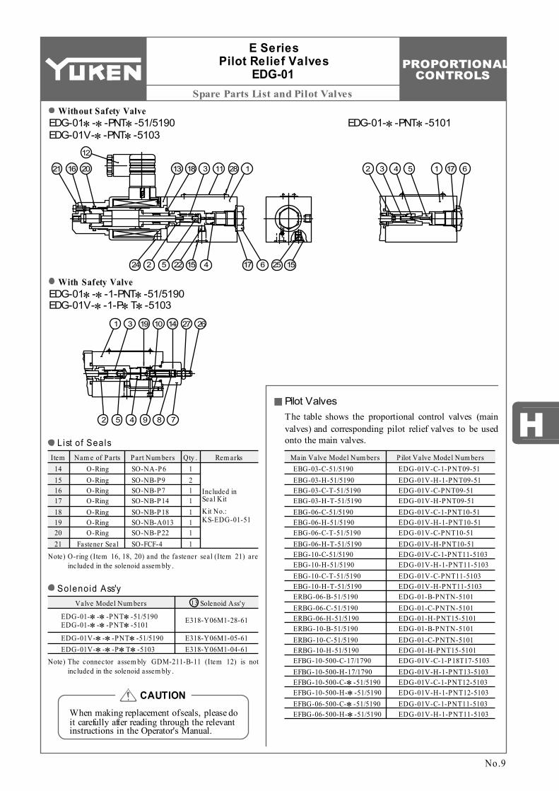
Spare Parts List and Pilot Valves
ItemSO-NA-P6 SO-NB-P9 SO-NB-P7 SO-NB-P14 SO-NB-P18 SO-NB-A013 SO-NB-P22 SO-FCF-4
Nam e of Parts Part Num bers Qty .O-Ring O-Ring O-Ring O-Ring O-Ring O-Ring O-Ring
Fastener Seal
1 2 1 1 1 1 1 1
Rem arks
Included in Seal Kit Kit No.: KS-EDG-01-51
14 15 16 17 18 19 20 21
Valve Model Num bers Solenoid Ass'y13
EDG-01V-∗-∗-PNT∗-51/5190 EDG-01V-∗-∗-P∗T∗-5103
EDG-01-∗-∗-PNT∗-51/5190 EDG-01-∗-∗-PNT∗-5101
E318-Y06M1-05-61 E318-Y06M1-04-61
E318-Y06M1-28-61
Main Valve Model Num bers Pilot Valve Model Num bersEBG-03-C-51/5190 EBG-03-H-51/5190 EBG-03-C-T-51/5190 EBG-03-H-T-51/5190 EBG-06-C-51/5190 EBG-06-H-51/5190 EBG-06-C-T-51/5190 EBG-06-H-T-51/5190 EBG-10-C-51/5190 EBG-10-H-51/5190 EBG-10-C-T-51/5190 EBG-10-H-T-51/5190 ERBG-06-B-51/5190 ERBG-06-C-51/5190 ERBG-06-H-51/5190 ERBG-10-B-51/5190 ERBG-10-C-51/5190 ERBG-10-H-51/5190 EFBG-10-500-C-17/1790 EFBG-10-500-H-17/1790 EFBG-10-500-C-∗-51/5190 EFBG-10-500-H-∗-51/5190 EFBG-06-500-C-∗-51/5190 EFBG-06-500-H-∗-51/5190
EDG-01V-C-1-PNT09-51 EDG-01V-H-1-PNT09-51 EDG-01V-C-PNT09-51 EDG-01V-H-PNT09-51 EDG-01V-C-1-PNT10-51 EDG-01V-H-1-PNT10-51 EDG-01V-C-PNT10-51 EDG-01V-H-PNT10-51 EDG-01V-C-1-PNT11-5103 EDG-01V-H-1-PNT11-5103 EDG-01V-C-PNT11-5103 EDG-01V-H-PNT11-5103 EDG-01-B-PNTN-5101 EDG-01-C-PNTN-5101 EDG-01-H-PNT15-5101 EDG-01-B-PNTN-5101 EDG-01-C-PNTN-5101 EDG-01-H-PNT15-5101 EDG-01V-C-1-P18T17-5103 EDG-01V-H-1-PNT13-5103 EDG-01V-C-1-PNT12-5103 EDG-01V-H-1-PNT12-5103 EDG-01V-C-1-PNT11-5103 EDG-01V-H-1-PNT11-5103
Without Safety Valve
With Safety Valve
12
2021 16 13 18 3 11 28 1
5224 22 15 4 17 6 25 15
32 4 5 1 17 6
31 19 10 14 27 26
2 5 4 9 8 7
E Series Pilot Relief Valves
EDG-01
No.9
EDG-01∗-∗-PNT∗-51/5190 EDG-01V-∗-PNT∗-5103
EDG-01-∗-PNT∗-5101
EDG-01∗-∗-1-PNT∗-51/5190 EDG-01V-∗-1-P∗T∗-5103
When making replacement of seals, please do it carefully after reading through the relevant instructions in the Operator's Manual.
CAUTION
List of Seals
Note) O-ring (Item 16, 18, 20) and the fastener seal (Item 21) are included in the solenoid assem bly .
Solenoid Ass'y
Note) The connector assem bly GDM-211-B-11 (Item 12) is not included in the solenoid assem bly .
Pilot ValvesThe table shows the proportional control valves (main valves) and corresponding pilot relief valves to be used onto the main valves.
PROPORTIONAL CONTROLS
Interchangeability between Current and New
94.5
(3
.72)
94.5
(3
.72)
217(8.54)Fully Extended
52 (2.05)
Fully ExtendedSolenoid Ass'y
E318-∗ -∗ -50 E318-∗ -∗ -60
12
Manual Pressure Adj. Screw 3(.12) Hex.Soc.
Adaptor 22(.87) Hex.
26.5(1.04)
86.6(3.41)
191.5(7.54)
26.5(1.04)
86.7(3.41)
190.5(7.50)
216(8.50)Fully Extended
52 (2.05)
Fully ExtendedSolenoid Ass'y
E318-∗ -∗ -61Air Vent 3(.12) Hex. Soc.
3 Places
Air Vent 3(.12) Hex. Soc. Manual Pressure
Adj. Screw 3(.12) Hex.Soc.
1 21 2
E Series Pilot Relief Valves
EDG-01
No.10
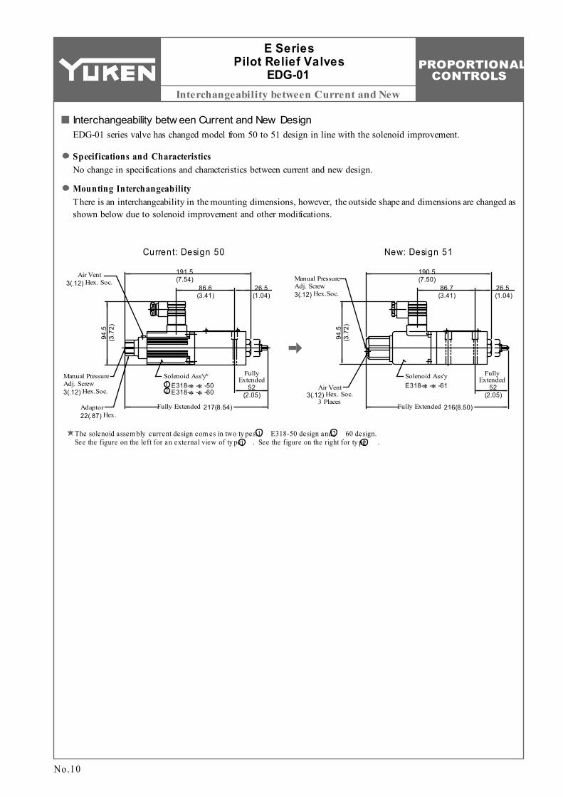
Current: Design 50
Interchangeability betw een Current and New DesignEDG-01 series valve has changed model from 50 to 51 design in line with the solenoid improvement.
Specifications and CharacteristicsNo change in specifications and characteristics between current and new design.
Mounting InterchangeabilityThere is an interchangeability in the mounting dimensions, however, the outside shape and dimensions are changed as shown below due to solenoid improvement and other modifications.
New: Design 51
The solenoid assem bly current design com es in two ty pes: E318-50 design and 60 design. See the figure on the left for an external view of ty pe . See the figure on the right for ty pe .
PROPORTIONAL CONTROLS
1
12
H
Specifications / Model Number Designation
1. 2.
Model NumbersEBG-03
Description
Coil Resistance Hysteresis Repeatability Approx. Mass
Rated Current
Proportional Electro-Hy draulic Relief Valve
EB :
EBSeries Num ber
GTy pe of
Mounting
-03 -C -T -51
Sub-plate Mounting
G:
03
Valve Size
Pres. Adj . Range MPa (PSI)
W ith Safety Valve
None:
W ithout Safety Valve
T :
Safety Valve Design Num ber
51
EBG-06 EBG-10
Max. Flow
Min. Flow
Max. Operating Pres.
Ω
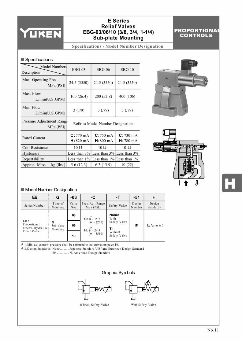
C: 770 mAH: 820 mA
24.5 (3550)
100 (26.4)
3 (.79)
06
C:∗ - 15.7 (∗ - 2275)
H:∗ - 24.5 (∗ - 3550)
10
C:750 mAH:800 mA
C: 730 mAH: 780 mA
Refer to Model Number Designation
24.5 (3550)
200 (52.8)
3 (.79)
24.5 (3550)
400 (106)
3 (.79)
MPa (PSI)
L/min(U.S.GPM)
L/min(U.S.GPM)
Pressure Adjustment Range MPa (PSI)
kg (lbs.)
10 Less than 3% Less than 1%
5.6 (12.3)
Ω10 Less than 3% Less than 1%
6.3 (13.9)
Ω10 Less than 3% Less than 1%
10 (22)
Design Standards
∗
Refer to
Graphic Symbols
W ith Safety ValveW ithout Safety Valve
Specifications
Model Number Designation
No.11
E Series Relief Valves
EBG-03/06/10 (3/8, 3/4, 1-1/4) Sub-plate Mounting
Min. adjustm ent pressure shall be referred to the curves on page 16.Design Standards: None
90Japanese Standard "JIS" and European Design Standard N. Am erican Design Standard
........... ...............

PROPORTIONAL CONTROLS
Sub-plate / Instructions / Others
M12 40 Lg. M16 50 Lg. M20 60 Lg.
×
Valve Model
Num bers
Japanese Standard "JIS"Sub-plate
Model Num bers
European Design StandardSub-plate
Model Num bers
N. Am erican Design StandardSub-plate
Model Num bersThread
SizeThread
SizeThread
Size
EBG-03
EBG-06
EBG-10
Japanese Standard "JIS" & European Design Standard N. Am erican Design Standard Qty .Socket Head Cap ScrewValve
Model Num bers
EBG-03 EBG-06 EBG-10
××
×××
4 4 4
2.4 (5.3) 3.1 (6.8)
4.7 (10.4) 5.7 (12.6) 8.4 (18.5)
10.3 (22.7)
BGM-03-20 BGM-03X-20 BGM-06-20 BGM-06X-20 BGM-10-20 BGM-10X-20
Rc 3/8 Rc 1/2 Rc 3/4 Rc 1
Rc 1-1/4 Rc 1-1/2
BGM-03-3080 BGM-03X-3080 BGM-06-3080 BGM-06X-3080 BGM-10-3080 BGM-10X-3080
BGM-03-2090 BGM-03X-2090 BGM-06-2090 BGM-06X-2090 BGM-10-2090 BGM-10X-2090
3/8 BSP.F 1/2 BSP.F 3/4 BSP.F 1 BSP.F
1-1/4 BSP.F 1-1/2 BSP.F
3/8 NPT 1/2 NPT 3/4 NPT 1 NPT
1-1/4 NPT 1-1/2 NPT
Approx. Mass
kg (lbs)
L/min
U.S.GPM
Addi
tiona
l Pre
ssur
e
MPaPSI
0
0
0
Flow Rate
25 50 75 100
5 10 15 20 25
1
2
3
0
100
200
300
400
EBG-03 EBG-06
L/min
U.S.GPM
0
0Flow Rate
50 100 150 200
10 20 30 40 50
Addi
tiona
l Pre
ssur
e
MPaPSI
01
2
3
0
600
200
700
400
4
5
L/min
U.S.GPM
0
0Flow Rate
100 200 300 400
20 40 60 80 100
EBG-10
Addi
tiona
l Pre
ssur
e
MPaPSI900
0
6
5
4
3
2
1
800
600
400
200
0
AttachmentMounting Bolts
Sub-plates are available. Specify the sub-plate model number from the table above. When sub-plates are not used, the mounting surface should have a good machined finish.
Sub-plate
1/2 - 13 UNC 1-1/2 Lg. 5/8 - 11 UNC 2 Lg. 3/4 - 10 UNC 2-1/4 Lg.
Applicable Pow er AmplifiersFor stable performance, it is recommended that Yuken's applicable power amplifiers be used (for details see Catalogue No. Pub. EC-1305).
Model Numbers: AME-D-10-∗-20 AME-D2-1010-∗-10 SK1022-∗-∗-11
InstructionsSafety ValveThe pressure of the safety valve for EBG-03 is preset at the value equal to the upper limit of the pressure adjustment range plus 2 MPa (290 PSI) subject to a flow rate of 50 L/min (13.2 U.S.GPM). The same for EBG-06 is preset at the value equal to the upper limit of the pressure adjustment range plus 3.5 MPa (510 PSI) subject to a flow rate of 100 L/min (26.4 U.S.GPM). The same for EBG-10 is preset at the value equal to the upper limit of the pressure adjustment range plus 4 MPa (580 PSI) subject to a flow rate of 200 L/min (52.8 U.S.GPM). In case where the upper limit of operating pressure is low or the upper limit of flow rate to be used is different from the specified maximum flow, please adjust and determine the setting pressure of the safety valve at the value calculated from the following formula. Setting pressure = (Operating pressure upper limit) + (Additional pressure indicated blow)
E Series Relief Valves EBG-03/06/10
To lower the setting pressure, turn the safety valve pressure adjustment screw anti-clockwise. After adjustment, be sure to tighten the lock nut.
No.12
SK1015-11 (For DC power supply) AMN-D-10 (For DC power supply)
PROPORTIONAL CONTROLS
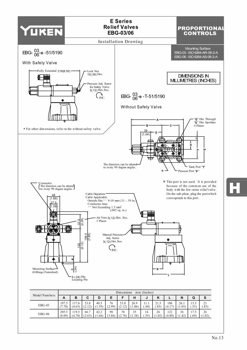
Installation DrawingMounting Surface
EBG-03 : ISO 6264-AR-06-2-A EBG-06 : ISO 6264-AS-08-2-A
H
N S13.5 (.53)17.5 (.69)
21 (.83)
26 (1.02)
Q26.1
(1.03)36
(1.42)
L
EBG-03
EBG-06
197.5 (7.78)205.5 (8.09)
53.8 (2.12)66.7
(2.63)
40.3 (1.59)42.2
(1.66)
76 (2.99)
98 (3.86)
26.9 (1.06)
35 (1.38)
21.5 (.85)
26 (1.02)
106 (4.17)
122 (4.80)
11.1 (.44)
14 (.55)
117.6 (4.63)119.5 (4.70)
53.8 (2.12)
70 (2.76)
Model Num bersA B C D E F H J K
Dim ensions m m (Inches)
Pressure Adj. Screw for Safety Valve 3(.12) Hex.Soc.
INC.
216(8.50)Fully Extended Lock Nut 10(.39) Hex.
39(1.54)
"Q" Dia. Through "S" Dia. Spotface 4 Places
Pressure Port "P"Tank Port "T"
The direction can be altered to every 90 degree angles.
27.5(1.08)
Cable Departure Cable Applicable: Outside Dia. 8-10 mm (.31 - .39 in.) Conductor Area
2 Not Exceeding 1.5 mm (.002 sq. in.)
. . .
. . .
Mounting Surface (O-Rings Furnished)
H
D
JF E
B C
A
Manual Pressure Adj. Screw
3(.12) Hex.Soc.
INC.
6 (.2
4)K
6 (.24) Dia. Locating Pin
48(1.89)
Connector The direction can be altered to every 90 degree angles.
130
(5.1
2)57
.5
(2.2
6)19
9.5
(7.8
5)
N
L
Air Vent 3(.12) Hex. Soc. 3 Places
E Series Relief Valves
EBG-03/06
EBG- -∗-51/5190
With Safety Valve
For other dim ensions, refer to the without safety valve.
Without Safety Valve
No.13
03 06
EBG- -∗-T-51/519003 06
This port is not used. It is provided because of the com m on use of the body with the low-noise relief valve. On the sub-plate, plug the port which corresponds to this port.
DIMENSIONS IN MILLIMETRES (INCHES)
PROPORTIONAL CONTROLS
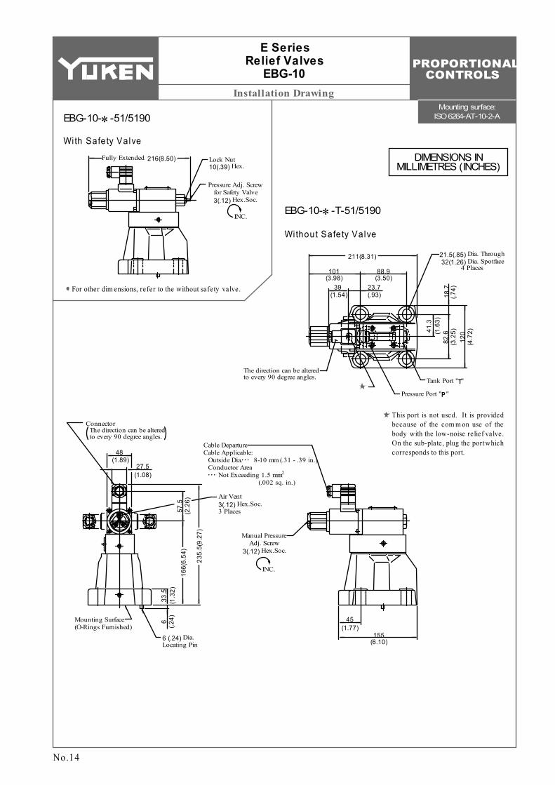
Installation DrawingMounting surface:
ISO 6264-AT-10-2-A
Pressure Adj. Screw for Safety Valve 3(.12) Hex.Soc.
INC.
216(8.50)Fully Extended Lock Nut 10(.39) Hex.
39(1.54)
Pressure Port "P"
Tank Port "T"The direction can be altered to every 90 degree angles.
Cable Departure Cable Applicable: Outside Dia. 8-10 mm (.31 - .39 in.) Conductor Area
2 Not Exceeding 1.5 mm (.002 sq. in.)
. . .
. . .
Mounting Surface (O-Rings Furnished)
Manual Pressure Adj. Screw
3(.12) Hex.Soc.
INC.
6 (.2
4)
6 (.24) Dia. Locating Pin
48(1.89)
Connector The direction can be altered to every 90 degree angles.
57.5
(2
.26)
23.7(.93)
101(3.98)
88.9(3.50)
211(8.31) 21.5(.85) Dia. Through 32(1.26) Dia. Spotface
4 Places
18.7
(.74)
82.6
(3
.25)41
.3
(1.6
3)
120
(4.7
2)27.5
(1.08)
166(
6.54
)
235.
5(9.
27)
33.5
(1
.32)
45(1.77)
155(6.10)
Air Vent 3(.12) Hex.Soc. 3 Places
E Series Relief Valves
EBG-10
EBG-10-∗-51/5190
With Safety Valve
For other dim ensions, refer to the without safety valve.
Without Safety Valve
EBG-10-∗-T-51/5190
This port is not used. It is provided because of the com m on use of the body with the low-noise relief valve. On the sub-plate, plug the port which corresponds to this port.
No.14
DIMENSIONS IN MILLIMETRES (INCHES)
PROPORTIONAL CONTROLS
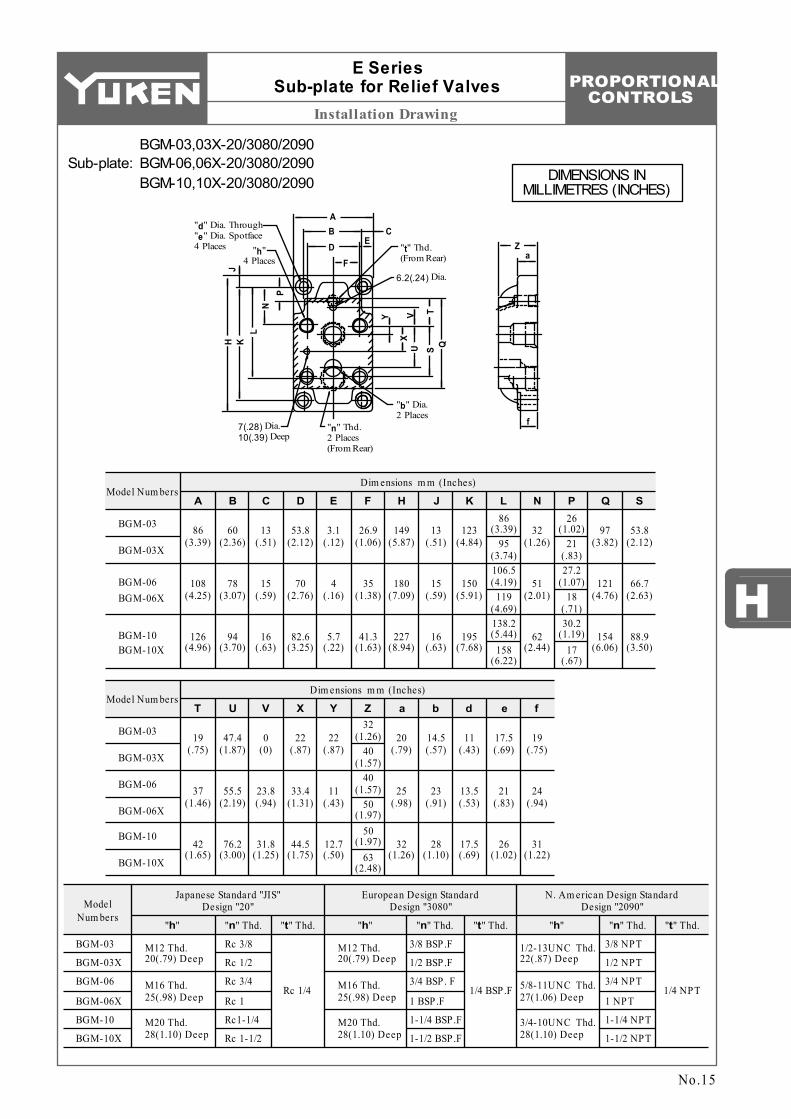
Installation Drawing
H
86 (3.39)
Model Num bers
BGM-03
BGM-03X
Model Num bers
BGM-03
BGM-03X
BGM-06
BGM-06X
BGM-10
BGM-10X
Dim ensions m m (Inches)
A B C D E F H J K L N P Q S
Dim ensions m m (Inches)
T U V X Y Z a b d e f
95 (3.74)106.5 (4.19)
119 (4.69)138.2 (5.44)
158 (6.22)
26 (1.02)
21 (.83)27.2
(1.07)18
(.71)30.2
(1.19)17
(.67)
86 (3.39)
108 (4.25)
126 (4.96)
60 (2.36)
78 (3.07)
94 (3.70)
13 (.51)
15 (.59)
16 (.63)
53.8 (2.12)
70 (2.76)
82.6 (3.25)
3.1 (.12)
4 (.16)
5.7 (.22)
26.9 (1.06)
35 (1.38)
41.3 (1.63)
149 (5.87)
180 (7.09)
227 (8.94)
13 (.51)
15 (.59)
16 (.63)
123 (4.84)
150 (5.91)
195 (7.68)
32 (1.26)
51 (2.01)
62 (2.44)
97 (3.82)
121 (4.76)
154 (6.06)
53.8 (2.12)
66.7 (2.63)
88.9 (3.50)
19 (.75)
37 (1.46)
42 (1.65)
47.4 (1.87)
55.5 (2.19)
76.2 (3.00)
0 (0)
23.8 (.94)
31.8 (1.25)
22 (.87)
33.4 (1.31)
44.5 (1.75)
22 (.87)
11 (.43)
12.7 (.50)
32 (1.26)
40 (1.57)
40 (1.57)
50 (1.97)
50 (1.97)
63 (2.48)
14.5 (.57)
23 (.91)
28 (1.10)
11 (.43)
13.5 (.53)
17.5 (.69)
17.5 (.69)
21 (.83)
26 (1.02)
19 (.75)
24 (.94)
31 (1.22)
20 (.79)
25 (.98)
32 (1.26)
Model Num bers
BGM-03
BGM-03X
BGM-06
BGM-06X
BGM-10
BGM-10X
Japanese Standard "JIS" Design "20"
European Design Standard Design "3080"
N. Am erican Design Standard Design "2090"
"h" "n" Thd. "t" Thd.
Rc 3/8
Rc 1/2
Rc 3/4
Rc 1
Rc1-1/4
Rc 1-1/2
3/8 BSP.F
1/2 BSP.F
3/4 BSP. F
1 BSP.F
1-1/4 BSP.F
1-1/2 BSP.F
3/8 NPT
1/2 NPT
3/4 NPT
1 NPT
1-1/4 NPT
1-1/2 NPT
Rc 1/4 1/4 BSP.F 1/4 NPT
M12 Thd. 20(.79) Deep
M16 Thd. 25(.98) Deep
M20 Thd. 28(1.10) Deep
M12 Thd. 20(.79) Deep
M16 Thd. 25(.98) Deep
M20 Thd. 28(1.10) Deep
1/2-13UNC Thd. 22(.87) Deep
5/8-11UNC Thd. 27(1.06) Deep
3/4-10UNC Thd. 28(1.10) Deep
"h" "n" Thd. "t" Thd. "h" "n" Thd. "t" Thd.
BGM-06 BGM-06X
BGM-10 BGM-10X
Za
f
ABD
F
CE
Y V T
XU S Q
PN
LKH
J"d" Dia. Through "e" Dia. Spotface 4 Places "h"
4 Places
7(.28) Dia. 10(.39) Deep
"n" Thd. 2 Places (From Rear)
"b" Dia. 2 Places
6.2(.24) Dia.
"t" Thd. (From Rear)
BGM-03,03X-20/3080/2090BGM-06,06X-20/3080/2090BGM-10,10X-20/3080/2090
Sub-plate:
No.15
E Series Sub-plate for Relief Valves
DIMENSIONS IN MILLIMETRES (INCHES)
PROPORTIONAL CONTROLS
Typical Performance Characteristics
EBG-03 EBG-06 EBG-10
275
MPaPSI2.0
250
200
150
100
50
0
1.6
1.2
0.8
0.4
0
Min
. Adj
ustm
ent P
ress
ure
0 25 50 75 100
0 5 10 15 20 25
Flow Rate
L /min
U.S.GPM
275
MPaPSI2.0
250
200
150
100
50
0
1.6
1.2
0.8
0.4
0
Min
. Adj
ustm
ent P
ress
ure
0 50 100 150 200
0 10 20 30 40 50
Flow Rate
L /min
U.S.GPM
275
MPaPSI2.0
250
200
150
100
50
0
1.6
1.2
0.8
0.4
0
Min
. Adj
ustm
ent P
ress
ure
0 100 200 300 400
0 20 40 60 80 100
Flow Rate
L /min
U.S.GPM
EBG-03-C
Trapped Oil Volum e Viscosity
: :
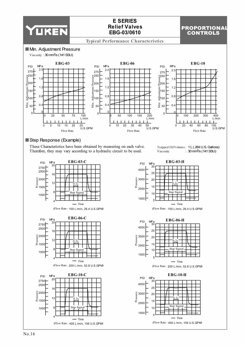
1 L (.264 U.S. Gallons) 2 30 mm /s (141 SSU)
2750
MPaPSI20
16
12
8
4
2500
2000
1500
1000
0.2s
Step Signal
Time
Pres
sure
EBG-03-H
4000
MPaPSI30
3000
2000
1000
25
20
15
10
5
Pres
sure
Time(Flow Rate : 100 L /min, 26.4 U.S.GPM) (Flow Rate : 100 L /min, 26.4 U.S.GPM)
EBG-06-C2750
MPaPSI20
Pres
sure
16
12
8
4
2500
2000
1500
1000
0.2s
Step Signal
Time(Flow Rate : 200 L /min, 52.8 U.S.GPM)
Pres
sure
EBG-10-C2750
MPaPSI20
16
12
8
4
2500
2000
1500
1000
EBG-06-HMPaPSI
Pres
sure
Time(Flow Rate : 200 L /min, 52.8 U.S.GPM)
4000
3000
2000
1000
30
25
20
15
10
5
Time(Flow Rate : 400 L /min, 106 U.S.GPM)
0.2s
Step Signal
MPaPSI
Pres
sure
4000
3000
2000
1000
30
25
20
15
10
5Time
(Flow Rate : 400 L /min, 106 U.S.GPM)
0.2s
Step Signal
0.2s
Step Signal
0.2s
Step Signal
EBG-10-H
Viscosity : 2 30 mm /s (141 SSU)
No.16
E SERIES Relief Valves EBG-03/0610
Min. Adjustment Pressure
Step Response (Example)These Characteristics have been obtained by measuring on each valve. Therefore, they may vary according to a hydraulic circuit to be used.
PROPORTIONAL CONTROLS
H
Typical Performance Characteristics
EBG-03
3500
MPaPSI
Pres
sure
25
20
15
10
5
0
3000
2500
2000
1500
1000
500
00
Input Current mA200 400 600 800 1000
EBG-03-C
EBG-03-H
EBG-06
3500
MPaPSI
Pres
sure
25
20
15
10
5
0
3500
2500
2000
1500
1000
500
0
EBG-06-H
EBG-06-C
0 200 400 600 800 1000
EBG-10
3500
MPaPSI
Pres
sure
25
20
15
10
5
0
3500
2500
2000
1500
1000
500
0
EBG-10-H
EBG-10-C
0 200 400 600 800 1000
0
Frequency (Hz)
Phas
e (d
eg.)
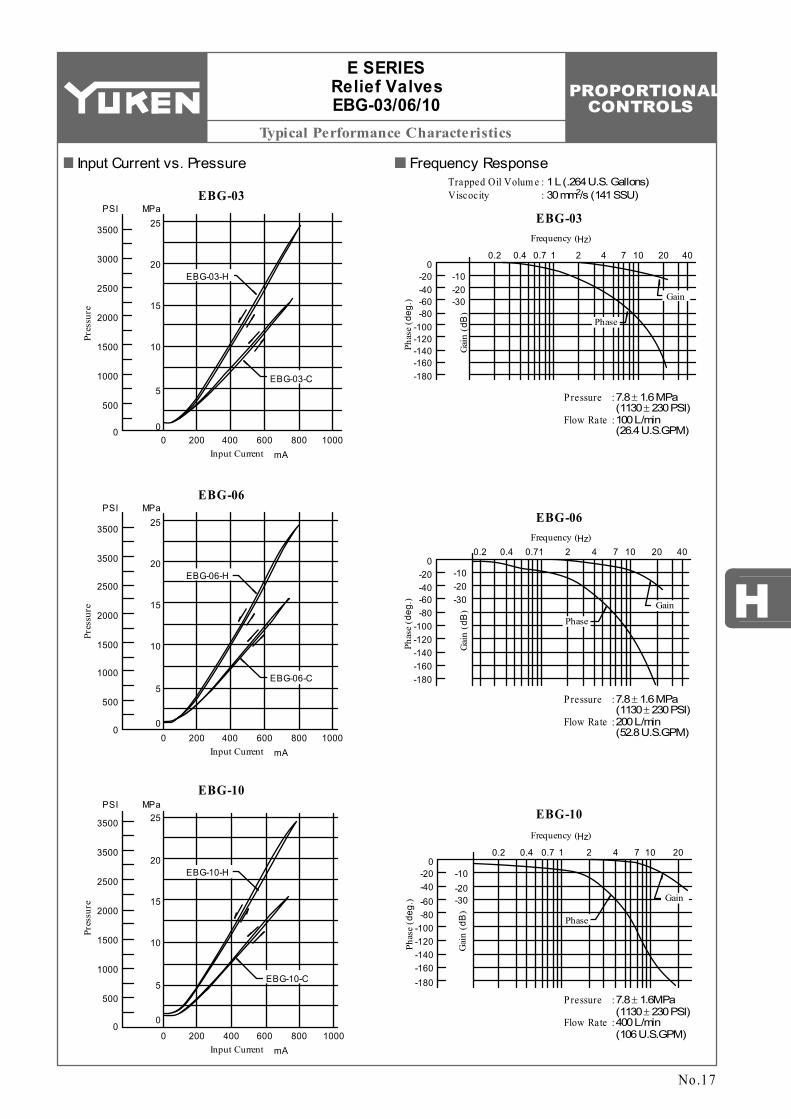
P ressure Flow Rate
: :
7.8 ± 1.6 MPa (1130 ± 230 PSI) 100 L/min (26.4 U.S.GPM)
-20-40-60-80
-100-120-140-160-180
-10-20-30
0.2 0.4 0.7 1 2 4 7 10 20 40
EBG-03
Trapped Oil Volum e Viscocity
: :1 L (.264 U.S. Gallons)
2 30 mm /s (141 SSU)
Phase
Gain
Frequency (Hz)
EBG-06
Pressure Flow Rate
: :
7.8 ± 1.6 MPa (1130 ± 230 PSI) 200 L/min (52.8 U.S.GPM)
0
Phas
e (d
eg.)
Gai
n (d
B)
-20-40-60-80
-100-120-140-160-180
-10-20-30
0.2 0.4 0.71 2 4 7 10 20 40
Phase
Gain
Frequency (Hz)
EBG-10
0
Phas
e (d
eg.)
Gai
n (d
B)
-20-40-60-80
-100-120-140-160-180
-10-20-30
0.2 0.4 0.7 1 2 4 7 10 20
Pressure Flow Rate
: :
7.8 ± 1.6MPa (1130 ± 230 PSI) 400 L/min (106 U.S.GPM)
Phase
Gain
Input Current mA
Input Current mA
Gai
n (d
B)
No.17
E SERIES Relief Valves EBG-03/06/10
Input Current vs. Pressure Frequency Response
PROPORTIONAL CONTROLS
Typical Performance Characteristics
EBG-03-C
EBG-03-H24.9
PSI MPa
3600
Pres
sure
24.524.13500
235023002250
16.115.715.3
30 35 40 45 50 55 60 °C
°F
SSU
2 mm /s1401201009020253040506070
100125150200250300
Temperature
Viscosity
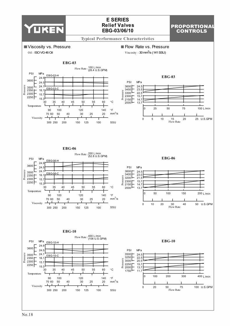
Flow Rate :
EBG-03100 L /min (26.4 U.S.GPM)
30 35 40 45 50 55 60 °C
°F
SSU
2 mm /s1401201009020253040506070
100125150200250300
Temperature
Viscosity
24.9PSI MPa
3600
Pres
sure
24.524.13500
235023002250
16.115.715.3
Flow Rate :
EBG-06200 L /min (52.8 U.S.GPM)
EBG-06-C
EBG-06-H
30 35 40 45 50 55 60 °C
°F
SSU
2 mm /s1401201009020253040506070
100125150200250300
Temperature
Viscosity
24.9PSI MPa
3600
Pres
sure
24.524.13500
235023002250
16.115.715.3
Flow Rate :
EBG-10400 L /min (106 U.S.GPM)
EBG-10-H
EBG-10-C
25 50 75 1000
0 5 10 15 20 25
24.5PSI MPa
3450
Pres
sure
3600
3300
21502300
2000
23.522.515.714.713.7
L /min
U.S.GPM
EBG-03
Flow Rate
50 100 150 2000
0 10 20 30 40 50
24.5PSI MPa
3400
Pres
sure
3600
3200
21502300
2000
23.021.515.714.713.7
L /min
U.S.GPM
EBG-06
Flow Rate
100 200 300 4000
0 20 50 75 100
24.5PSI MPa
3250
Pres
sure
3500
3000
20002250
1750
22.520.515.713.711.7
L /min
U.S.GPM
EBG-10
Flow Rate
No.18
E SERIES Relief Valves EBG-03/06/10
Viscosity vs. Pressure Flow Rate vs. PressureOil : ISO VG 46 Oil Viscosity : 2 30 mm /s (141 SSU)
PROPORTIONAL CONTROLS
Spare Parts List
H
P ilot Valve Model Num bers
Item
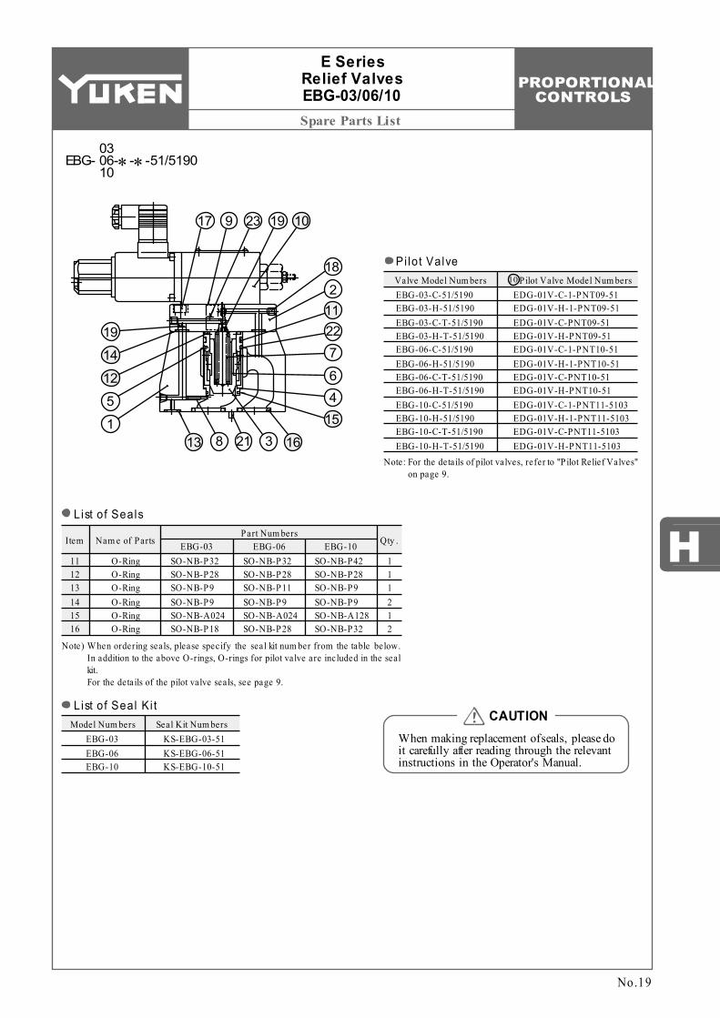
SO-NB-P32 SO-NB-P28 SO-NB-P9 SO-NB-P9 SO-NB-A024 SO-NB-P18
Nam e of Parts EBG-03 Qty .
O-Ring O-Ring O-Ring O-Ring O-Ring O-Ring
1 1 1 2 1 2
11 12 13 14 15 16
Model Num bers Seal Kit Num bersEBG-03 EBG-06 EBG-10
Valve Model Num bersEBG-03-C-51/5190 EBG-03-H-51/5190 EBG-03-C-T-51/5190 EBG-03-H-T-51/5190 EBG-06-C-51/5190 EBG-06-H-51/5190 EBG-06-C-T-51/5190 EBG-06-H-T-51/5190 EBG-10-C-51/5190 EBG-10-H-51/5190 EBG-10-C-T-51/5190 EBG-10-H-T-51/5190
EDG-01V-C-1-PNT09-51 EDG-01V-H-1-PNT09-51 EDG-01V-C-PNT09-51 EDG-01V-H-PNT09-51 EDG-01V-C-1-PNT10-51 EDG-01V-H-1-PNT10-51 EDG-01V-C-PNT10-51 EDG-01V-H-PNT10-51 EDG-01V-C-1-PNT11-5103 EDG-01V-H-1-PNT11-5103 EDG-01V-C-PNT11-5103 EDG-01V-H-PNT11-5103
10
Part Num bers
SO-NB-P32 SO-NB-P28 SO-NB-P11 SO-NB-P9 SO-NB-A024 SO-NB-P28
EBG-06SO-NB-P42 SO-NB-P28 SO-NB-P9 SO-NB-P9 SO-NB-A128 SO-NB-P32
EBG-10
KS-EBG-03-51 KS-EBG-06-51 KS-EBG-10-51
17 9 23 19 10
18
211
15
7
64
2219
5
14
12
116321813
E Series Relief Valves EBG-03/06/10
No.19
When making replacement of seals, please do it carefully after reading through the relevant instructions in the Operator's Manual.
CAUTION
List of Seals
Note) W hen ordering seals, please specify the seal kit num ber from the table below. In addition to the above O-rings, O-rings for pilot valve are included in the seal kit. For the details of the pilot valve seals, see page 9.
List of Seal Ki t
EBG- -∗-∗-51/519003 06 10
Pi lot Valve
Note: For the details of pilot valves, refer to "P ilot Relief Valves"on page 9.
PROPORTIONAL CONTROLS
Interchangeability between Current and New
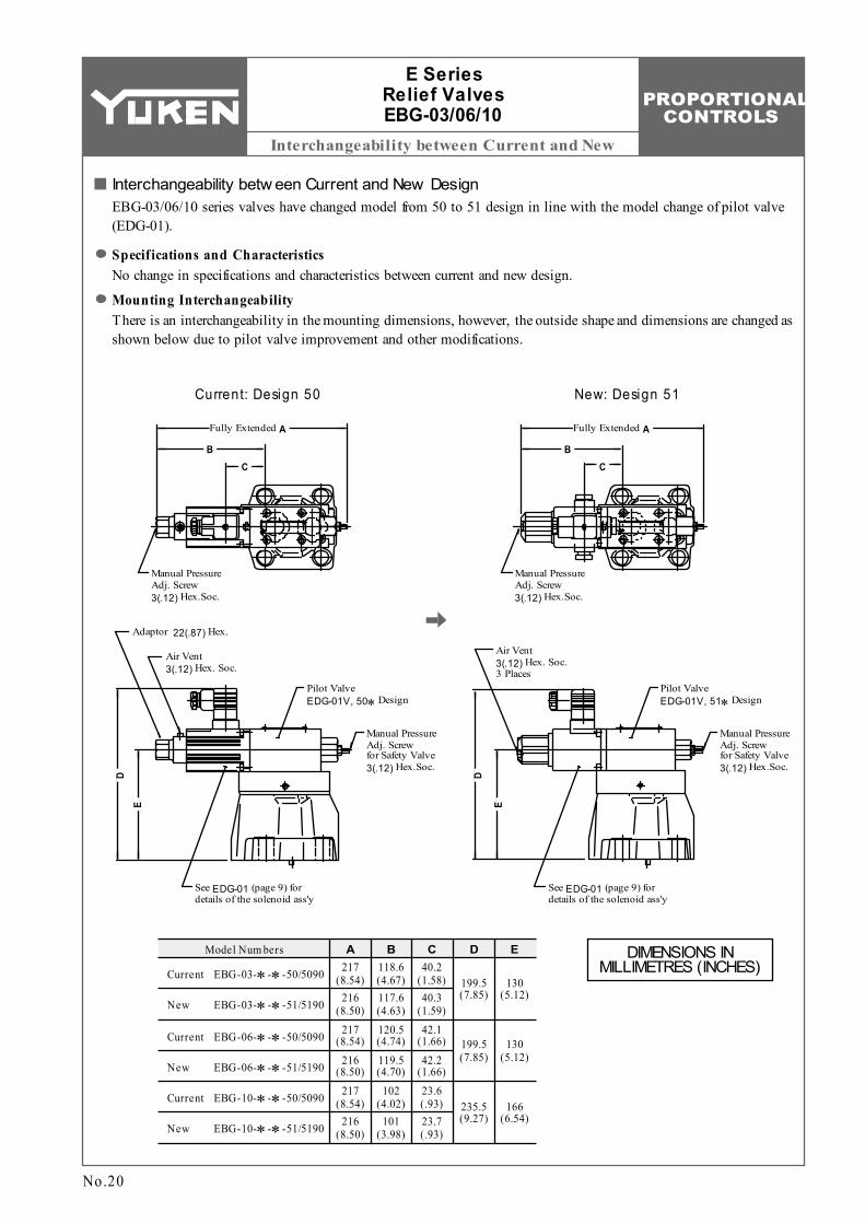
217 (8.54) 199.5
(7.85)130
(5.12)
Model Num bers A B C D E118.6 (4.67)
40.2 (1.58)
216 (8.50)
117.6 (4.63)
40.3 (1.59)
120.5 (4.74)
42.1 (1.66)
119.5 (4.70)
42.2 (1.66)
102 (4.02)
23.6 (.93)
101 (3.98)
23.7 (.93)
199.5 (7.85)
130 (5.12)
235.5 (9.27)
166 (6.54)
EBG-03-∗-∗-50/5090
EBG-03-∗-∗-51/5190
EBG-06-∗-∗-50/5090
EBG-06-∗-∗-51/5190
EBG-10-∗-∗-50/5090
EBG-10-∗-∗-51/5190
Current
New
Current
New
Current
New
217 (8.54)
216 (8.50)
217 (8.54)
216 (8.50)
Manual Pressure Adj. Screw 3(.12) Hex.Soc.
Adaptor 22(.87) Hex.
Air Vent 3(.12) Hex. Soc.
AFully Extended
BC
Manual Pressure Adj. Screw 3(.12) Hex.Soc.
AFully Extended
BC
Manual Pressure Adj. Screw for Safety Valve 3(.12) Hex.Soc.
Pilot Valve EDG-01V, 50∗Design
See EDG-01 (page 9) for details of the solenoid ass'y
DE
Manual Pressure Adj. Screw for Safety Valve 3(.12) Hex.Soc.
Pilot Valve EDG-01V, 51∗Design
See EDG-01 (page 9) for details of the solenoid ass'y
D
E
Air Vent 3(.12) Hex. Soc. 3 Places
E Series Relief Valves EBG-03/06/10
No.20
Current: Design 50
Interchangeability betw een Current and New DesignEBG-03/06/10 series valves have changed model from 50 to 51 design in line with the model change of pilot valve (EDG-01).
Specifications and CharacteristicsNo change in specifications and characteristics between current and new design.
Mounting InterchangeabilityThere is an interchangeability in the mounting dimensions, however, the outside shape and dimensions are changed as shown below due to pilot valve improvement and other modifications.
New: Design 51
DIMENSIONS IN MILLIMETRES (INCHES)
PROPORTIONAL CONTROLS
H
Specifications / Model Number Designation
Model NumbersDescription
Coil Resistance Hysteresis Repeatability Approx. Mass
Rated Current
Proportional Electro-Hy draulic Reducing and Relieving Valve
ERB:
ERBSeries Num ber
GTy pe of
Mounting
-06 -C -51
Sub-plate Mounting
G:
Valve Size
Secondary Pres. Adj . Range MPa (PSI)
Design Num ber
51
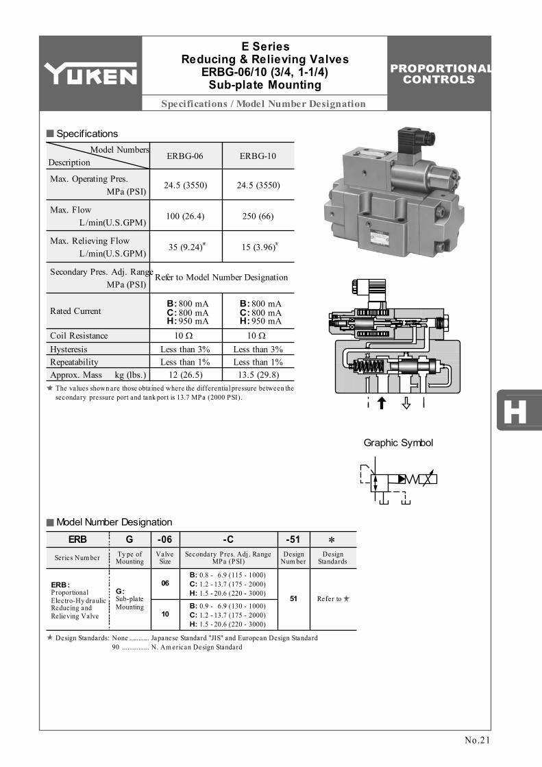
ERBG-06 ERBG-10
Max. Flow
Max. Relieving Flow
Max. Operating Pres.
Ω
C: 800 mAH: 950 mA
06
10
Refer to Model Number Designation
24.5 (3550)
100 (26.4)
35 (9.24)
24.5 (3550)
250 (66)
15 (3.96)
MPa (PSI)
L/min(U.S.GPM)
L/min(U.S.GPM)
Secondary Pres. Adj. Range MPa (PSI)
kg (lbs.)
10 Less than 3% Less than 1%
12 (26.5)
Design Standards
∗
Refer to
B: 800 mAC: 800 mAH: 950 mA
B: 800 mA
Ω10 Less than 3% Less than 1%
13.5 (29.8)
C:H:
B: 0.8 - 6.9 (115 - 1000)1.2 - 13.7 (175 - 2000)1.5 - 20.6 (220 - 3000)
C:H:
B: 0.9 - 6.9 (130 - 1000)1.2 - 13.7 (175 - 2000)1.5 - 20.6 (220 - 3000)
Graphic Symbol
Specifications
Model Number Designation
No.21
E Series Reducing & Relieving Valves
ERBG-06/10 (3/4, 1-1/4) Sub-plate Mounting
Design Standards: None 90
Japanese Standard "JIS" and European Design Standard N. Am erican Design Standard
........... ...............
The values shown are those obtained where the differential pressure between the secondary pressure port and tank port is 13.7 MPa (2000 PSI).
PROPORTIONAL CONTROLS
Sub-plate / Instructions / Others
M10 70 Lg. M10 70 Lg.
×
Valve Model
Num bers
Japanese Standard "JIS"Sub-plate
Model Num bers
European Design StandardSub-plate
Model Num bers
N. Am erican Design StandardSub-plate
Model Num bersThread
SizeThread
SizeThread
SizeERBG-06 ERBG-10
Japanese Standard "JIS" & European Design Standard N. Am erican Design Standard Qty .Socket Head Cap ScrewValve
Model Num bers
ERBG-06 ERBG-10 ×
××
4 6
3.0 (6.6) 6.5 (14.3)
ERBGM-06-20 ERBGM-10-10
Rc 3/4 Rc 1-1/4
3/4 BSP.F 1-1/4 BSP.F
3/4 NPT 1-1/4 NPT
ERBGM-06-2080 ERBGM-10-1080
ERBGM-06-2090 ERBGM-10-1090
Approx. Mass
kg (lbs.)
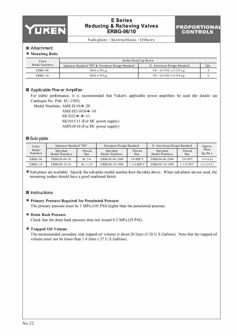
AttachmentMounting Bolts
Sub-plates are available. Specify the sub-plate model number from the table above. When sub-plates are not used, the mounting surface should have a good machined finish.
Sub-plate
3/8 - 16 UNC 2-3/4 Lg. 3/8 - 16 UNC 2-3/4 Lg.
Applicable Pow er AmplifierFor stable performance, it is recommended that Yuken's applicable power amplifiers be used (for details see Catalogue No. Pub. EC-1305).
Model Numbers: AME-D-10-∗-20 AME-D2-1010-∗-10 SK1022-∗-∗-11 SK1015-11 (For DC power supply) AMN-D-10 (For DC power supply)
Instructions
Primary Pressure Required for Preselected PressureThe primary pressure must be 1 MPa (145 PSI) higher than the preselected pressure.
E Series Reducing & Relieving Valves
ERBG-06/10
No.22
Drain Back PressureCheck that the drain back pressure does not exceed 0.2 MPa (29 PSI).
Trapped Oil VolumeThe recommended secondary side trapped oil volume is about 20 liters (5.28 U.S.Gallons). Note that the trapped oil volume must not be lower than 1.4 liters (.37 U.S.Gallons).
PROPORTIONAL CONTROLS
Installation Drawing
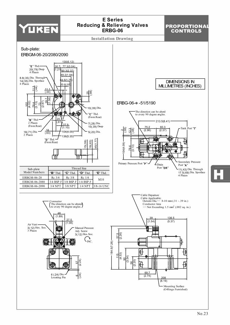
HThread Size
"B" Thd. "C" Thd. "D" Thd. "E" Thd.Sub-plate
Model Num bers
ERBGM-06-20 ERBGM-06-2080 ERBGM-06-2090
Rc 3/4 3/4 BSP.F 3/4 NPT
Rc 3/8 3/8 BSP.F 3/8 NPT
Rc 1/4 1/4 BSP.F 1/4 NPT 3/8-16 UNC
M10
75.2 (2.96)
Primary Pressure Port "P"
Tank Port "T"
The direction can be alterd to every 90 degree angles.
27.5(1.08)
Mounting Surface (O-Rings Furnished)
6 (.2
4)6 (.24) Dia. Locating Pin
48(1.89)
Connector The direction can be altered to every 90 degree angles.
57
(2.2
4)
Air Vent 3(.12) Hex. Soc. 3 Places
15(.5
9)11.1(.44)
10(.39) Dia.
8.8(.35) Dia. Through 14(.55) Dia. Spotface 4 Places 20.6(.81)
44.5(1.75)
49.2(1.94)60.3(2.37)
30.7(1.21)
77.3(3.04)
130(5.12)"E" Thd. 20(.79) Deep 4 Places
"C" Thd. (From Rear)
73
(2.8
7)
25
(.98)
39.7
(1
.56)
79.4
(3
.13)
11.3
(.4
4)
102
(4.0
2)
"B" Thd. 2 Places (From Rear)
18(.71) Dia. 2 Places
7(.28) Dia. 10(.39) Deep
5(.20) Dia.
"D" Thd. (From Rear)
20.7(.81)
27.9(1.10)104(4.09)
136(5.35)
16(.63)
16(.6
3)
45(1
.77)
60.3 (2.37)
213.5(8.41)
11(.43) Dia. Through 17.5(.69) Dia. Spotface 4 Places
2 (.0
8)
12.3
(.4
8)
104(
4.09
)
79.4
(3
.13)
Secondary Pressure Port "A"Drain
Port "DR"
Manual Pressure Adj. Screw 3(.12) Hex.Soc.
INC.
208(8.19)
69.7(2.74)
136.5(5.37)
39(1.54)
184.
5(7.
26)
115
(4.5
3)57
.5
(2.2
6)90
(3
.54)
56
(2.2
0)
Cable Departure Cable Applicable: Outside Dia. 8-10 mm (.31 - .39 in.) Conductor Area
2 Not Exceeding 1.5 mm (.002 sq. in.)
. . .
. . .
E Series Reducing & Relieving Valves
ERBG-06
Sub-plate: ERBGM-06-20/2080/2090
No.23
ERBG-06-∗-51/5190
DIMENSIONS IN MILLIMETRES (INCHES)
PROPORTIONAL CONTROLS
Installation Drawing
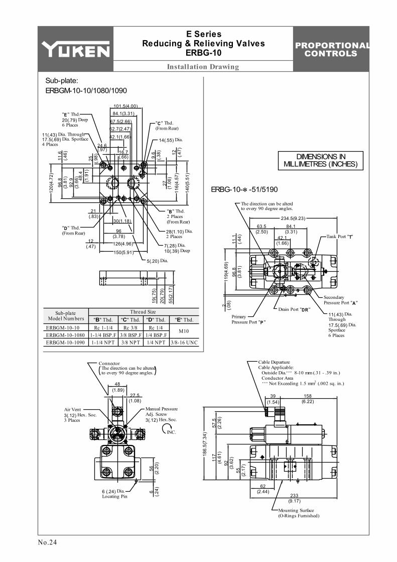
Thread Size"B" Thd. "C" Thd. "D" Thd. "E" Thd.
Sub-plate Model Num bers
ERBGM-10-10 ERBGM-10-1080 ERBGM-10-1090
Rc 1-1/4 1-1/4 BSP.F 1-1/4 NPT
Rc 3/8 3/8 BSP.F 3/8 NPT
Rc 1/4 1/4 BSP.F 1/4 NPT 3/8-16 UNC
M10
63.5 (2.50)
Primary Pressure Port "P"
Tank Port "T"
The direction can be alterd to every 90 degree angles.
27.5(1.08)
Mounting Surface (O-Rings Furnished)
6 (.2
4)6 (.24) Dia. Locating Pin
48(1.89)
Connector The direction can be altered to every 90 degree angles.
56
(2.2
0)
Air Vent 3(.12) Hex. Soc. 3 Places
19(.7
5)
14(.55) Dia.24.6 (.97)
62.7(2.47)67.5(2.66)
84.1(3.31)101.5(4.00)
"E" Thd. 20(.79) Deep 6 Places "C" Thd.
(From Rear)
48.4
(1
.91)
25
(.98)
92.9
(3
.66)
11.6
(.4
6)
"B" Thd. 2 Places (From Rear)
28(1.10) Dia. 2 Places
7(.28) Dia. 10(.39) Deep
5(.20) Dia.
"D" Thd. (From Rear)
30(1.18)
126(4.96)
150(5.91)
12(.47)
20(.7
9)
55(2
.17)
84.1 (3.31)
234.5(9.23)
11(.43) Dia. Through 17.5(.69) Dia. Spotface 6 Places
2 (.0
8)11
.1
(.44)
119(
4.69
)
96.8
(3
.81)
Secondary Pressure Port "A"
Drain Port "DR"
Manual Pressure Adj. Screw 3(.12) Hex.Soc.
INC.
233(9.17)
62(2.44)
158(6.22)
39(1.54)
186.
5(7.
34)
117
(4.6
1)57
.5
(2.2
6)92
(3
.62)
55
(2.1
7)
11(.43) Dia. Through 17.5(.69) Dia. Spotface 4 Places
16.7 (.66)
42.1(1.66)
96.8
(3
.81)
9.6
(.38)
120(
4.72
)
140(
5.51
)
116(
4.57
)
27
(1.0
6)12
(.4
7)
21(.83)
96 (3.78) 42.1
(1.66)
Cable Departure Cable Applicable: Outside Dia. 8-10 mm (.31 - .39 in.) Conductor Area
2 Not Exceeding 1.5 mm (.002 sq. in.)
. . .
. . .
E Series Reducing & Relieving Valves
ERBG-10
Sub-plate: ERBGM-10-10/1080/1090
ERBG-10-∗-51/5190
No.24
DIMENSIONS IN MILLIMETRES (INCHES)
PROPORTIONAL CONTROLS
H
Typical Performance Characteristics
ERBG-06-B
1200
MPaPSI
Seco
ndar
y Pr
essu
re
8.8
7.8
5.9
3.9
2.0
0
1000
800
600
400
200
0
0.1s
Step Signal
Time
Seco
ndar
y Pr
essu
re
3000MPaPSI21.6
2500
2000
1500
1000
500
0
19.6
15.7
11.8
7.8
3.9
0
ERBG-06-C
Time
0.1s
Step Signal
Seco
ndar
y Pr
essu
re
3500MPaPSI23.5
19.6
15.7
11.8
7.8
3.9
0
3000
2500
2000
1500
1000
500
0Time
ERBG-06-H
0.1s
Step Signal
ERBG-10-B
0.1s
Step Signal
Time
1400MPaPSI
Seco
ndar
y Pr
essu
re
9.8
7.8
5.9
3.9
2.0
0
1200
1000
800
600
400
200
0
ERBG-10-C
Time
0.1s
Step Signal
2750
MPaPSI
Seco
ndar
y Pr
essu
re
19.6
15.7
11.8
7.8
3.9
0
2500
2000
1500
1000
500
0
Time
ERBG-10-H
4000MPaPSI
Seco
ndar
y Pr
essu
re
27.5
3500
3000
2500
2000
1500
1000
500
0
23.5
19.6
15.7
11.8
7.8
3.9
0
0.1s
Step Signal
No.25
E SERIES Reducing & Relieving Valves
ERBG-06/10
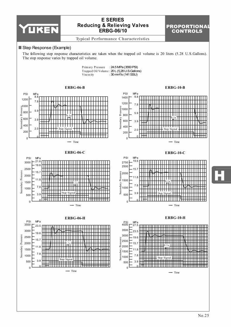
Step Response (Example)The following step response characteristics are taken when the trapped oil volume is 20 liters (5.28 U.S.Gallons). The step response varies by trapped oil volume.
Prim ary Pressure Trapped Oil Volum e Viscocity
: : :
24.5 MPa (3550 PSI) 20 L (5.28 U.S.Gallons)
2 30 mm /s (141 SSU)
PROPORTIONAL CONTROLS
Typical Performance Characteristics
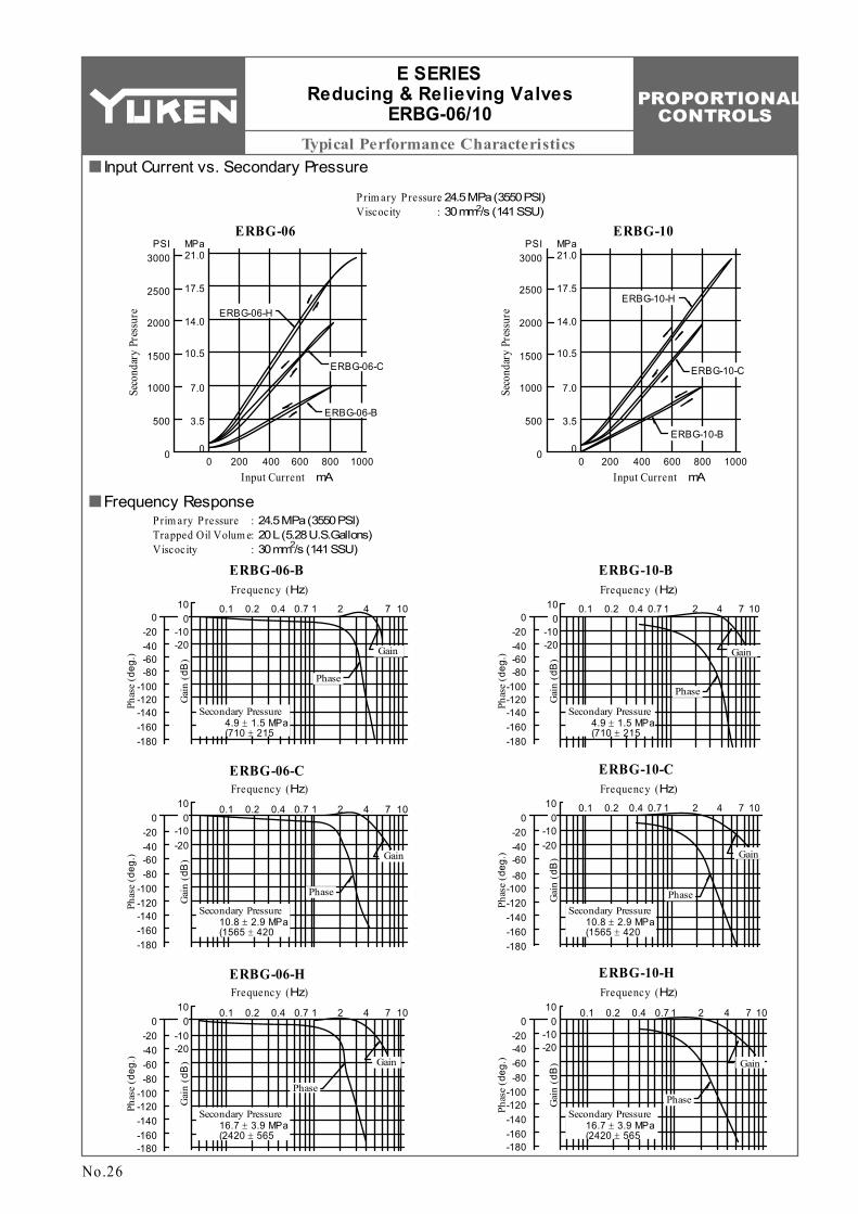
Prim ary Pressure Viscocity
: :24.5 MPa (3550 PSI)
2 30 mm /s (141 SSU)
ERBG-06
3000MPaPSI21.0
17.5
14.0
10.5
7.0
3.5
0
2500
2000
1500
1000
500
00 200 400 600 800 1000
Seco
ndar
y Pr
essu
re
Input Current mA
ERBG-06-H
ERBG-06-C
ERBG-06-B
MPaPSI21.0
17.5
14.0
10.5
7.0
3.5
00200 400 600 800 1000
Seco
ndar
y Pr
essu
re
Input Current mA
ERBG-10
ERBG-10-H
ERBG-10-C
ERBG-10-B
Prim ary Pressure Trapped Oil Volum e Viscocity
: : :
24.5 MPa (3550 PSI) 20 L (5.28 U.S.Gallons)
2 30 mm /s (141 SSU)
0.1 0.2 0.4 0.7 1 2 4 7 10100
-10-20
0-20-40-60-80
-100-120-140-160-180
Gai
n (d
B)
Phas
e (d
eg.)
Phase
Gain
Secondary Pressure 4.9 ± 1.5 MPa (710 ± 215
ERBG-06-BFrequency (Hz)
0.1 0.2 0.4 0.7 1 2 4 7 10100
-10-20
0-20-40-60-80
-100-120-140-160-180
ERBG-10-B
Phase
Gain
Secondary Pressure 4.9 ± 1.5 MPa (710 ± 215
100
-10-20
0-20-40-60-80
-100-120-140-160-180
0.1 0.2 0.4 0.7 1 2 4 7 10
ERBG-06-C
Secondary Pressure 10.8 ± 2.9 MPa (1565 ± 420
Phase
Gain
0.1 0.2 0.4 0.7 1 2 4 7 10100
-10-20
0-20-40-60-80
-100-120-140-160-180
Phase
Gain
Secondary Pressure 10.8 ± 2.9 MPa (1565 ± 420
ERBG-10-C
10
-10-20
0-20-40-60-80
-100-120-140-160-180
0.1 0.2 0.4 0.7 1 2 4 7 10
ERBG-06-H
Secondary Pressure 16.7 ± 3.9 MPa (2420 ± 565
Phase
Gain
0.1 0.2 0.4 0.7 1 2 4 7 10100
-10-20
0-20-40-60-80
-100-120-140-160-180
Phase
Gain
Secondary Pressure 16.7 ± 3.9 MPa (2420 ± 565
ERBG-10-H
3000
2500
2000
1500
1000
500
0
0
Gai
n (d
B)
Phas
e ( d
eg.)
Frequency (Hz)
Gai
n (d
B)
Phas
e (d
eg.)
Frequency (Hz)
Gai
n (d
B)
Phas
e (d
eg.)
Frequency (Hz)
Gai
n (d
B)
Phas
e ( d
eg.)
Frequency (Hz)
Gai
n (d
B)
Phas
e ( d
eg.)
Frequency (Hz)
No.26
E SERIES Reducing & Relieving Valves
ERBG-06/10
Input Current vs. Secondary Pressure
Frequency Response
PROPORTIONAL CONTROLS
H
Typical Performance Characteristics
ERBG-06-B
20 40 60 80 1000
50 10 15 20 25Flow Rate
L /min
U.S.GPM
6.91000
Seco
ndar
y Pr
essu
re
PSI MPa
900
700600
500400
1000
6.45.94.94.43.93.42.92.4
1.00.5
0
ERBG-06-C
20 40 60 80 1000
50 10 15 20 25Flow Rate
L /min
U.S.GPM
13.72000PSI MPa
1900
14001300
1000900
600500
13.212.7
9.89.38.86.96.45.93.93.42.9
Seco
ndar
y Pr
essu
re
400
ERBG-06-H
20 40 60 80 1000
50 10 15 20 25Flow Rate
L /min
U.S.GPM
20.63000PSI MPa
2800
20001800
14001200
1000900
19.618.613.712.711.7
9.88.87.86.96.45.9
Seco
ndar
y Pr
essu
re
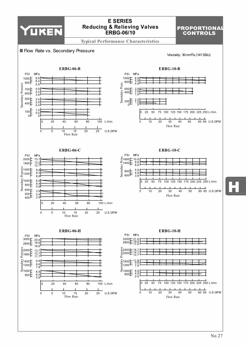
2 Viscosity : 30 mm /s (141 SSU)
ERBG-10-B
ERBG-10-C
ERBG-10-H
6.91000
Seco
ndar
y Pr
ess.
PSI MPa
5.94.9800
3.92.91.9
2.01.0
0
600400
2000
Flow Rate
250
65
L /min
U.S.GPM
2252001751501251007550250
6050403020100
Flow Rate
250
65
L /min
U.S.GPM
2252001751501251007550250
6050403020100
10.81600
Seco
ndar
y Pr
ess. PSI MPa
1400
800600
9.88.8
5.94.93.9
Flow Rate
250
65
L /min
U.S.GPM
2252001751501251007550250
6050403020100
21.63200
Seco
ndar
y Pr
essu
re
PSI MPa
19.617.6
16.714.712.7
11.89.87.8
6.94.92.9
2800
24002000
16001200
1000800
No.27
E SERIES Reducing & Relieving Valves
ERBG-06/10
Flow Rate vs. Secondary Pressure
PROPORTIONAL CONTROLS
Typical Performance Characteristics
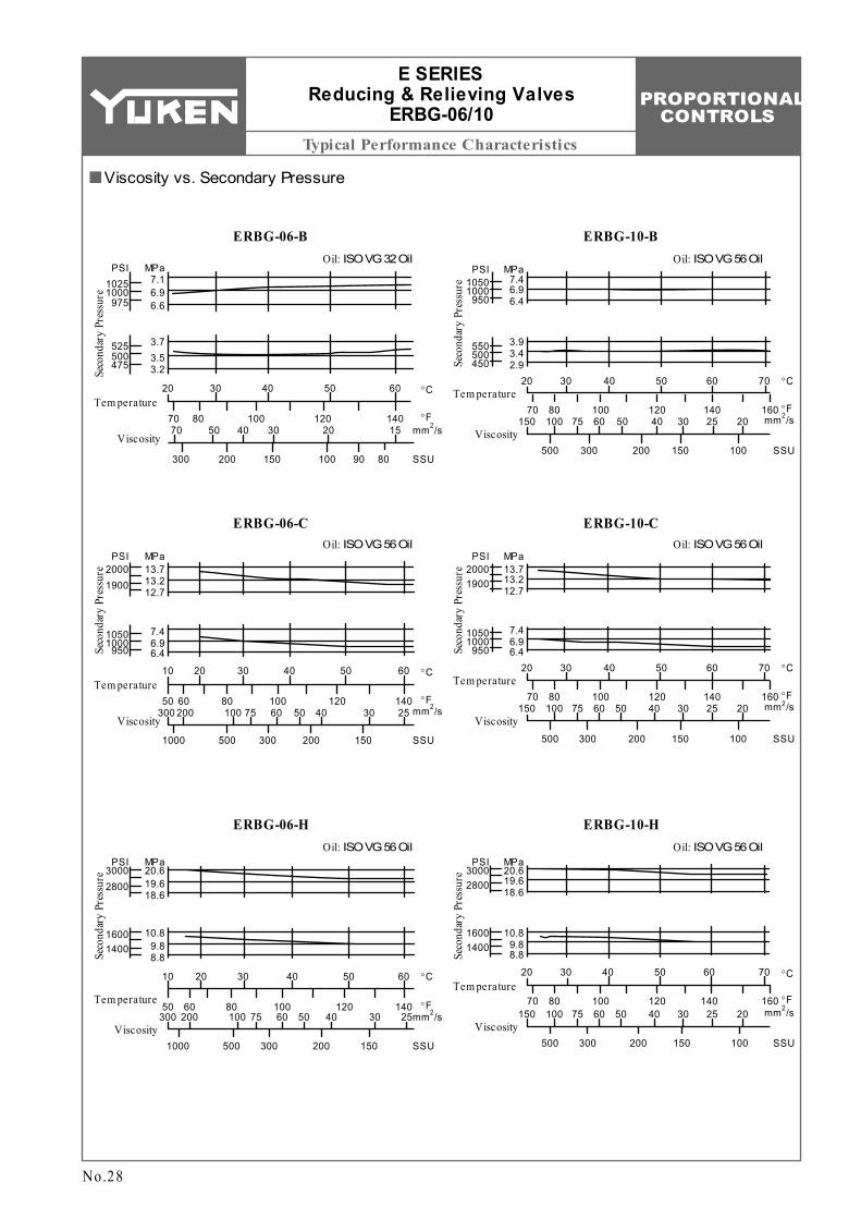
ERBG-10-BOil: ISO VG 56 Oil
70Tem perature
Viscosity
°C
°F
SSU
2 mm /s
6050403020
70 80 100 120 140 16020253040506075100150
500 300 200 150 100
7.41050
Seco
ndar
y Pr
essu
re
PSI MPa
6.96.4
1000950
3.95503.42.9
500450
ERBG-10-COil: ISO VG 56 Oil
70Tem perature
Viscosity
°C
°F
SSU
2 mm /s
6050403020
70 80 100 120 140 16020253040506075100150
500 300 200 150 100
13.72000
Seco
ndar
y Pr
essu
re
PSI MPa
13.212.7
1900
7.410506.96.4
1000950
ERBG-10-HOil: ISO VG 56 Oil
70Tem perature
Viscosity
°C
°F
SSU
2 mm /s
6050403020
70 80 100 120 140 16020253040506075100150
500 300 200 150 100
20.63000
Seco
ndar
y Pr
essu
re
PSI MPa
19.618.6
2800
10.816009.88.8
1400
ERBG-06-BOil: ISO VG 32 Oil
ERBG-06-COil: ISO VG 56 Oil
ERBG-06-HOil: ISO VG 56 Oil
Tem perature
60 °C
°F
SSU
2 mm /s140
25
150
5040302010
1201008060503040506075100200300
Viscosity2003005001000
Seco
ndar
y Pr
essu
re 20.63000PSI MPa
19.618.6
2800
10.89.88.8
16001400
Tem perature60 °C
°F
SSU
2 mm /s14025
150
5040302010
1201008060503040506075100200300
Viscosity2003005001000
Seco
ndar
y Pr
essu
re 13.72000PSI MPa
13.212.7
1900
7.46.96.4
1050950
1000
Tem perature60 °C
°F
SSU
2 mm /s14015
90
50403020
12010080702030405070
Viscosity
100150200300
Seco
ndar
y Pr
essu
re
7.11025PSI MPa
6.96.6
1000
3.73.53.2
525
475500
975
80
No.28
E SERIES Reducing & Relieving Valves
ERBG-06/10
Viscosity vs. Secondary Pressure
PROPORTIONAL CONTROLS
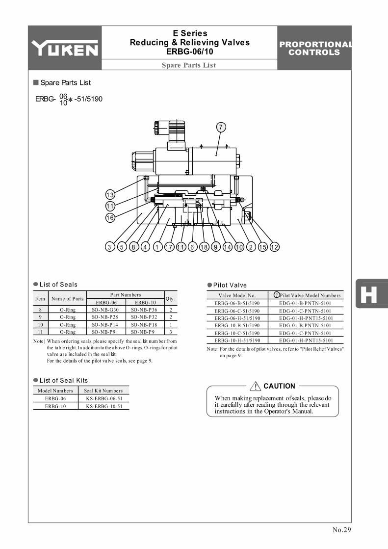
Spare Parts List
H P ilot Valve Model Num bersItem
SO-NB-G30 SO-NB-P28 SO-NB-P14 SO-NB-P9
Nam e of Parts Qty .
O-Ring O-Ring O-Ring O-Ring
2 2 1 3
8 9
10 11
Model Num bers Seal Kit Num bersERBG-06 ERBG-10
Valve Model No.ERBG-06-B-51/5190 ERBG-06-C-51/5190 ERBG-06-H-51/5190 ERBG-10-B-51/5190 ERBG-10-C-51/5190 ERBG-10-H-51/5190
EDG-01-B-PNTN-5101 EDG-01-C-PNTN-5101 EDG-01-H-PNT15-5101 EDG-01-B-PNTN-5101 EDG-01-C-PNTN-5101 EDG-01-H-PNT15-5101
7Part Num bers
SO-NB-P36 SO-NB-P32 SO-NB-P18 SO-NB-P9
ERBG-06 ERBG-10
KS-ERBG-06-51 KS-ERBG-10-51
7
143 5 8 17 11 6 18 9 14 10 2 15 12
13
11
16
E Series Reducing & Relieving Valves
ERBG-06/10
No.29
When making replacement of seals, please do it carefully after reading through the relevant instructions in the Operator's Manual.
CAUTION
List of Seals
Note) W hen ordering seals, please specify the seal kit num ber from the table right. In addition to the above O-rings, O-rings for pilot valve are included in the seal kit. For the details of the pilot valve seals, see page 9.
List of Seal Ki ts
ERBG- -∗-51/519006 10
Pi lot Valve
Note: For the details of pilot valves, refer to "P ilot Relief Valves" on page 9.
Spare Parts List
PROPORTIONAL CONTROLS
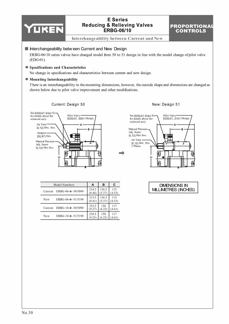
Interchangeability between Current and New
Model Num bers A B C136.5 (5.37)
115 (4.53)
158 (6.22)
214.5 (8.44)213.5 (8.41)235.5 (9.27)234.5 (9.23)
ERBG-06-∗-50/5090
ERBG-06-∗-51/5190
ERBG-10-∗-50/5090
ERBG-10-∗-51/5190
Current
New
Current
New
136.5 (5.37)
158 (6.22)
115 (4.53)
117 (4.61)
117 (4.61)
Manual Pressure Adj. Screw 3(.12) Hex.Soc.
Adaptor 22(.87) Hex.
Air Vent 3(.12) Hex. Soc.
Pilot Valve EDG-01, 5001 Design
AB
C
AB
C
Pilot Valve EDG-01, 5101 Design
See EDG-01 (page 8) for details about the solenoid ass'y
Manual Pressure Adj. Screw 3(.12) Hex.Soc.
See EDG-01 (page 8) for details about the solenoid ass'y
Air Vent 3(.12) Hex. Soc. 3 Places
E Series Reducing & Relieving Valves
ERBG-06/10
No.30
Current: Design 50
Interchangeability betw een Current and New DesignERBG-06/10 series valves have changed model from 50 to 51 design in line with the model change of pilot valve (EDG-01).
Specifications and CharacteristicsNo change in specifications and characteristics between current and new design.
Mounting InterchangeabilityThere is an interchangeability in the mounting dimensions, however, the outside shape and dimensions are changed as shown below due to pilot valve improvement and other modifications.
New: Design 51
DIMENSIONS IN MILLIMETRES (INCHES)

![[XLS]owmnahar.comowmnahar.com/nahar_polyfilm/pdf/0910.xlsx · Web view44.1 24.5 49 49 24.5 24.5 16.45 24.5 24.5 68.599999999999994 24.5 0.35 0.35 4.9000000000000004 24.5 24.5 0.35](https://img.pdfslide.us/doc/110x75/5aad36587f8b9a693f8e15c2/xls-view441-245-49-49-245-245-1645-245-245-68599999999999994-245-035.jpg)