Embed Size (px)
Citation preview

ACTUATORS
1 1
2
J
1 2
DescriptionCJT35
Standard Type Switch Set TypeCJT70 CJT140 CJT210 CJT35L CJT70L CJT140L
Cylinder BoreNominal PressureMin. Operating PressureOperating SpeedMax. Storke
mm (In.)MPa (PSI)
MPa (PSI)
mm/s (In./s)
mm (In.)
Refer to the "Cylinder Bore Selection Chart"3.5 (510) 7 (1020) 14 (2030) 21 (3050) 3.5 (510) 7 (1020) 14 (2030)Less than 0.1 (14.5)
Less than 0.3 (43.5)
Less than 0.3 (43.5)
Less than 0.3 (43.5)
Less than 0.1 (14.5)
Less than 0.3 (43.5)
Less than 0.3 (43.5)
8 - 300 (.31 - 11.8)
8 - 400 (.31 - 15.7)
8 - 300 (.31 - 11.8)
8 - 300 (.31 - 11.8)
8 - 400 (.31 - 15.7)
1800 (70.9) 2000 (78.7) 1600 (63.0) 2000 (78.7)
Cylinder Bore
mm(ln.)
Standrd Type
CJT 140L
Switch Set Type
CJT 70LCJT 35LCJT 210CJT 140CJT 70CJT 35
32 (1.26)40 (1.57)50 (1.97)63 (2.48)80 (3.15)
100 (3.94)125 (4.92)140 (5.51)150 (5.91)160 (6.30)180 (7.09)200 (7.87)220 (8.66)250 (9.84)
No.1
Pub. EC-0801
Up to 21 MPa (3530 PSI)
"CJT" SERIES HYDRAULIC CYLINDERS Standard Type : CJT35 / CJT70 / CJT140 / CJT210
YUKEN's "CJT" Series Hydraulic Cylinders based on JIS B 8354 are provided with many mounting types so that they can be used for wide use of general purpose industrial machines such as machine tools. Moreover, Switch-Set "CJT" Series Hydraulic Cylinders with a proximity switch which facilitates detecting a position with a slide proximity switch on the cylinder body is also available.
Switch Set Type : CJT35L / CJT70L / CJT140L
Various mounting typesExcellent ability in low speed and high-precision operation.Gentle stop characteristics obtained with a smooth cushion effect.
. Max. Operating Speed is varied according to the Cylinder Bore. . Max. Stroke may be varied according to the Cylinder Bore. It also may be limited to lower value according to buckling strength. For details, consult Yuken.
Cylinder Bore Selection Chart
The mark in above chart show selectable Cylinder Bore.
Graphic Symbols
Std.Type Switch Set Type
This catalogue introduces the outline of CJT Series Hydraulic Cylinders. Consult Yuken when detailed material such as dimensions figures is required.
Specifications

ACTUATORS
1
1
Model Number Designation
1.
A Rod Side
B
C
D
Head Side
Type Usage Max. Load Indicator Light
S1, S3, S5 (Lead Wire) SB (Plug-in Connector)
T1, T3, T5 (Lead Wire) TB (Plug-in Connector)U1, U3, U5 (Lead Wire) UB (Plug-in Connector)W1, W3, W5 (Lead Wire) WB (Plug-in Connector)
Contact Switch
Contactless Switch
AC/DC for Relay & Sequencer
Large Volume Relay
AC for Relay & Sequencer
DC for Relay & Sequencer
24 V DC, 5-50 mA 100 V AC, 7-20 mA 200 V AC, 7-10 mA
100 V AC, 20-200 mA 200 V AC, 10-200 mA
85-265 V AC, 5-100 mA
10-30 V DC, 5-30 mA
Lighting when switch is ON
Lighting when switch is OFF
Lighting when switch is ON
No.2
"CJT" Series Hydraulic Cylinders Standard Type / Switch Set Type
Standard Type
Model Number Designation
Specification of Switch
Switch Set TypeComposition of basic model code is the same as of the above mentioned standard type. However the following under- lined marks shall be added.
(Ex.) CJT70 - LA 32 C 100 B - A B D - ∗ - 11
Max. Operating Pres.35: 3.5 MPa (510 PSI) 70: 7 MPa (1020 PSI) 140: 14 MPa (2030 PSI) 210: 21 MPa (3050 PSI) Mounting (Refer to the following page)
Cylinder Bore (mm)
Rod TypeB: C: S:
Heavy Duty Type (CJT70/140/210) Standard Type (CJT70/140) Special Type (CJT35)
Stroke (mm)
Options
Air Vent Position D: Left
Cushion Valve Position B: Right
Port Position A: Upward
Location of CushionB: R: H: N:
Both Sides Rod Side Head Side No Cushion
. Consult YUKEN when options is required.
(Ex.) CJT70L - LA32C100B - ABD - ∗ S1 2 - 11
Switch Set TypeOptions
Number of Switch1: 1 Pc. 2: 2 Pcs. 3: 3 Pcs.
Type of Switch (Refer to Table below)S1. T1: Lead Wire, 1m (3.3 ft.) S3. T3: Lead Wire, 3m (9.8 ft.) S5. T5: Lead Wire, 5m (16.4 ft.) SB. TB: Plug-in Connector U1. W1: Lead Wire, 1m (3.3 ft.) U3. W3: Lead Wire, 3m (9.8 ft.) U5. W5: Lead Wire, 5m (16.4 ft.) UB. WB: Plug-in Connector
Consult Yuken when options is required.
Options
Options
Applicable only for "CJT35L"
ACTUATORS
J
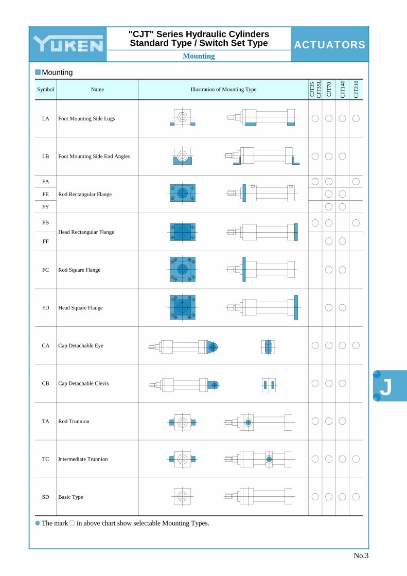
Mounting
CJT
210
CJT
140
CJT
70
CJT
35
CJT
35L
Foot Mounting Side Lugs
Foot Mounting Side End Angles
Rod Rectangular Flange
Head Rectangular Flange
Rod Square Flange
Head Square Flange
Cap Detachable Eye
Cap Detachable Clevis
Rod Trunnion
Intermediate Trunnion
Basic Type
Symbol
LA
LB
FA
FE
FY
FB
FF
FC
FD
CA
CB
TA
TC
SD
Name Illustration of Mounting Type
No.3
The mark in above chart show selectable Mounting Types.
"CJT" Series Hydraulic Cylinders Standard Type / Switch Set Type
Mounting