Embed Size (px)
Citation preview

UNVENTED HOT WATER SYSTEM
ANNUAL SERVICE REQUIRED
McDONALD ENGINEERSHOT WATER SYSTEMSFLEMINGTON ROAD, QUEENSWAY INDUSTRIAL ESTATE, GLENROTHES FIFE KY7 5QFTel : 01592 611123 Fax : 01592 611166Email : [email protected] Internet : www.mcdonald-engineers.com
FOR SPARES CALL 01592 611123
INSTRUCTIONSPLEASE LEAVE WITH HOUSEHOLDER
IMPORTANT - Failure to install and maintain this system in
accordance with these instructions will invalidate the
manufacturer’s warranty.
1 FOR SPARES CALL 01592 611123
IMPORTANT
Installation should only be carried out by a‘competent operative’ i.e. the installer musthave attended a recognised course inUnvented Hot Water Systems or receivedappropriate training in their apprenticeship.All registered operatives should carry anIdentification Card issued by the Institute ofUnvented Hot Water Systems or SNIPEF(Scottish and Northern Ireland PlumbingEmployers’ Federation), the ConstructionIndustry Training Board or the Institute ofPlumbers.
The unit should be handledwith care in order to avoid damage tovalves. It should be stored upright in itsbox in a dry place.
Full weights are available at the back ofthis booklet. The installation area shouldbe able to cope with this weight, incomingpipes and discharge pipe. Position theunit to suit the installation.
All connections are to the front to enableease of access. Ensure suitable space isleft for access for repair and/orreplacement of valves etc.
In areas with hard water we wouldrecommend restricting the temperatureand performing de-scaling procedures asrequired.
All the following instructions must becarried out: -
1. Installers should ensure incomingmains pressure is less than 12Bar andthat local authority approval forinstallation of Unvented Systems isgranted. Ensure adequate flowrate isavailable.
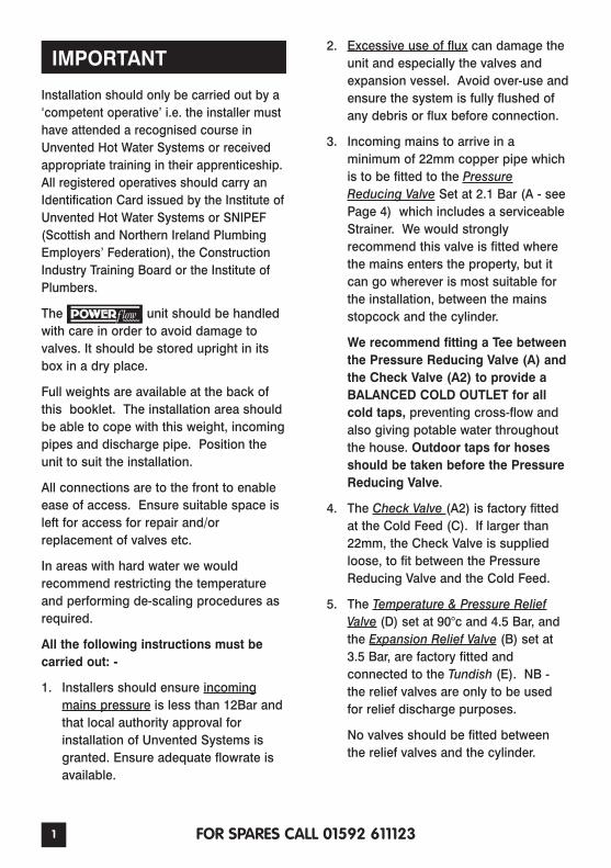
2. Excessive use of flux can damage theunit and especially the valves andexpansion vessel. Avoid over-use andensure the system is fully flushed ofany debris or flux before connection.
3. Incoming mains to arrive in aminimum of 22mm copper pipe whichis to be fitted to the PressureReducing Valve Set at 2.1 Bar (A - seePage 4) which includes a serviceableStrainer. We would stronglyrecommend this valve is fitted wherethe mains enters the property, but itcan go wherever is most suitable forthe installation, between the mainsstopcock and the cylinder.
We recommend fitting a Tee betweenthe Pressure Reducing Valve (A) andthe Check Valve (A2) to provide aBALANCED COLD OUTLET for allcold taps, preventing cross-flow andalso giving potable water throughoutthe house. Outdoor taps for hosesshould be taken before the PressureReducing Valve.
4. The Check Valve (A2) is factory fittedat the Cold Feed (C). If larger than22mm, the Check Valve is suppliedloose, to fit between the PressureReducing Valve and the Cold Feed.
5. The Temperature & Pressure ReliefValve (D) set at 90°c and 4.5 Bar, andthe Expansion Relief Valve (B) set at3.5 Bar, are factory fitted andconnected to the Tundish (E). NB -the relief valves are only to be usedfor relief discharge purposes.
No valves should be fitted betweenthe relief valves and the cylinder.
2FOR SPARES CALL 01592 611123
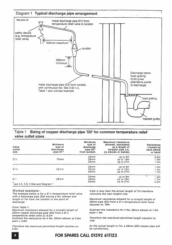
6. The Tundish (E), which shows visibledischarge from the Relief Valves, is tobe in a prominent, visible and safeposition away from any electricaldevices (likewise with the drainconnection) and within 500mm of theTemperature & Pressure Relief Valve(D). Pipework from the Tundish (E)must initially be vertical for a minimumof 300mm where possible and thenhave a continuous fall in excess of 1in 200. Pipework away from theTundish (E) should be in a minimum of22mm, of material suitable fortemperatures of 95°C and have aresistance to flow of water not greaterthan that of a straight pipe of 9 metres(each bend or elbow is equal to 0.8metre of resistance). See BBAInformation. Sheet No 33:1989 forfurther details - available from themanufacturer. Also note page 9 ofthese instructions.
7. The Expansion Vessel (F) charged at2.1 Bar, should either be fitted directlyto connection (M) on the cylinder, or ifspace dictates, securely to the wallwith the optional remote fixing kit andthe hose fitted between the vessel andconnection (M). On larger units, theVessel may be fitted between theCheck Valve and Cold Feed. Noisolating valve is allowed between theVessel and the Cold Feed.
8. Connect the 3kW 11” 240V ImmersionHeater/s BSEN 60335/2/73 (withmanual re-set cut out at 80°C) to thepower supply and earth them inaccordance with the current IEE wiringregulations. The fuse rating should be13 Amps. Do not at any time fitImmersion Heaters without a thermalcut-out.
9. On Indirect Units where a Coil is fittedto the cylinder, when supplied the TwoPort Motorised Zone Valve and DualThermostat Controller (J) must befitted in accordance with theinstruction details supplied with themfor the appropriate installation.
N.B. Indirects, are suitable for oil,gas and electric fired boilers on apumped, gravity or sealed system.(We would however recommend28mm Coil connections with a 28mmZone Valve on gravity systems).Maximum working pressure of thecoil is 3.5 Bar. All electrical wiring tothermostats, zone valve andimmersion heaters must be earthedand to current IEE Wiring Regulations.The fuse should generally be 3 Ampsbut refer to appliance instructions toconfirm this.
10. The Secondary Return (L) if supplied,should be plugged if not required. Ifthe Secondary System pipe-work isgreater than 15% of the unit capacity,a larger Expansion Vessel may needto be fitted - contact McDonaldEngineers.
11. Immersion Heaters (H) and the DualAquastat Controller (J) supplied withthe Indirect units should be set to nogreater than 60°C and the internalHigh Limit Thermostats are factory setno higher than 85°C. Always checkthis before switching on power.
Please see the checklist on page 4 to ensure all controls are present and correct.
3 FOR SPARES CALL 01592 611123
ONCE ALL THE PRECEDING INSTRUCTIONS HAVE BEENFOLLOWED, COMMISSION THE SYSTEM.
IMPORTANT
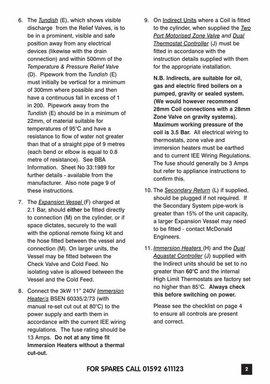
COMMISSIONING - These instructionsmust be followed.
After following the instructions on pages1 & 2 proceed as follows: -
1. Close the Drain-cock (I) at base ofcylinder.
2. Open a Hot Tap.
3. Fully open the Cold Mains Stopcockand fill Cylinder until water appears atthe Hot Tap.
4. Close the Hot Tap and attend each hotwater outlet in turn and ensure waterflow is obtained at each.
IT IS THE RESPONSIBILITY OF THEINSTALLATION ENGINEER TO CHECKAND ENSURE THAT ALL VALVES,FITTINGS AND IMMERSION/S AREPROPERLY SEALED AND WATERTIGHT.
5. Check the control thermostats on theImmersion Heater/s (H) and the DualThermostat (J) are set no higher than60°C and that the High LimitThermostats are set to no higher than85°C.
6. Ensure there is no discharge from theRelief Valves (B and D).
7. Switch on water heating system andcheck operation of the system.
IT IS EXTREMELY IMPORTANT TOFOLLOW ALL THE INSTRUCTIONSPREVIOUSLY MENTIONED, AS FAILURETO DO SO COULD BE DANGEROUS ORLEAD TO THE SYSTEM WORKINGINEFFICIENTLY.
4FOR SPARES CALL 01592 611123
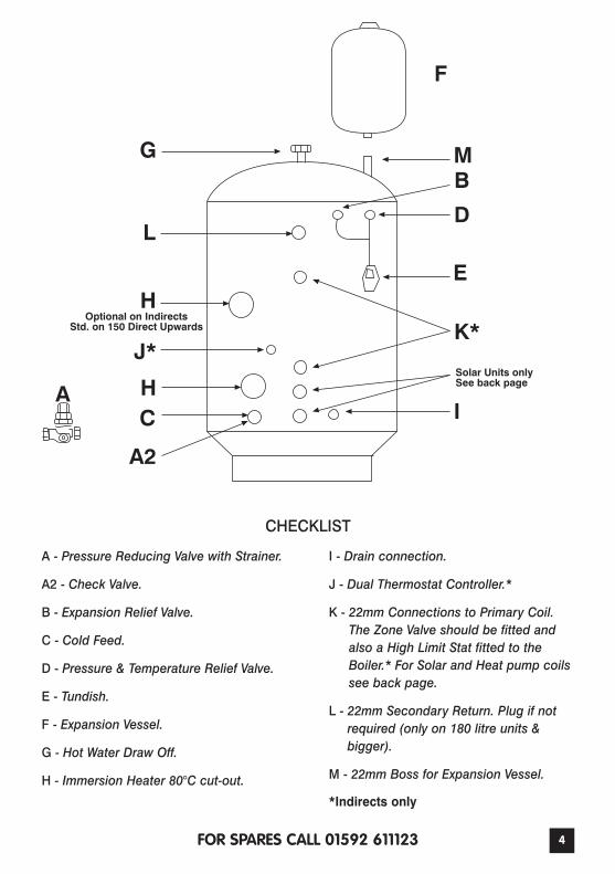
A - Pressure Reducing Valve with Strainer.
A2 - Check Valve.
B - Expansion Relief Valve.
C - Cold Feed.
D - Pressure & Temperature Relief Valve.
E - Tundish.
F - Expansion Vessel.
G - Hot Water Draw Off.
H - Immersion Heater 80°C cut-out.
I - Drain connection.
J - Dual Thermostat Controller.*
K - 22mm Connections to Primary Coil.The Zone Valve should be fitted andalso a High Limit Stat fitted to theBoiler.* For Solar and Heat pump coilssee back page.
L - 22mm Secondary Return. Plug if notrequired (only on 180 litre units &bigger).
M - 22mm Boss for Expansion Vessel.
*Indirects only
CHECKLIST
A
G M
F
B
D
E
K*
I
A2
CH
J*
H
L
Optional on IndirectsStd. on 150 Direct Upwards
Solar Units onlySee back page
A
5 FOR SPARES CALL 01592 611123
ANNUAL MAINTENANCE
should be serviced at leastonce a year by a competent operative.
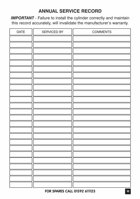
IMPORTANT - failure to maintain thissystem in accordance with theseinstructions will invalidate themanufacturer’s warranty. A maintenancerecord should be kept on the ANNUALSERVICE RECORD card provided onpage 10, we would recommend a serviceprogram is arranged on installation.Failure to maintain this record willinvalidate the manufacturer’s warranty.Contact your installer to arrange theappropriate service program.
ANNUAL SERVICE CHECKS
Expansion Relief Valve (B) - manuallyopen the twist cap and check that thewater is discharged and runs clearlythrough the Tundish (E) and out at thefinal discharge point. Ensure that thevalve re-seat/re-seals itself.
Pressure & Temperature Relief Valve (D) -repeat the above procedure. Ensure thatthe valve re-seat/re-seals itself.
Strainer (A) - turn off mains at stopcock.There will be a small amount of residualwater in the pipework, remove thecartridge from Pressure Reducing Valve(A), clean Strainer and replace.
Expansion Vessel (F) - Check Pressurevia the valve under the black cap on topof the vessel, while a hot tap is running.Ensure pressure is 2.1 Bar. Vessel can bere-charged if required as per “RechargingExpansion Vessel” on page 6 opposite.
PROBLEM SOLVING
DISCHARGE FROM EITHER OF THERELIEF VALVES INDICATES AMALFUNCTION IN THE SYSTEM ANDMUST BE INVESTIGATED IMMEDIATELY.
OVERHEATED HOT WATERDISCHARGE
In the unlikely event of overheated (90°C)water being discharged, the heat sourcei.e. the immersion heaters or the centralheating boiler should be switched offimmediately and a competent operativecalled out. Ensure that the discharge ofhot water or steam at the Tundish (E) orfinal discharge point causes no dangerand is not likely to injure anyone.
DO NOT SHUT OFF THE COLD WATERSUPPLY TO THE UNIT!!
DO NOT RE-USE UNTIL CHECKED ANDREPAIRED!!
ENSURE COMPONENTS ARE ISOLATEDFROM ELECTRICITY BEFOREINVESTIGATION!!
Once cold water has entered the unit anddisplaced the over heated water thuscooling it, check the thermostat andenergy cut out in the a) Immersion Heater,b) Thermostat, c) Boiler. Identify thefaulty component and replace with thecorrect component as supplied by themanufacturer and ensure that it worksbefore re-commissioning the system.
DO NOT FOR ANY REASON BY-PASS ANENERGY CUT-OUT.
Problem Solving continued on page 6...
6FOR SPARES CALL 01592 611123
WATER DISCHARGE
If water is occasionally being dischargedas the water is heated, this would belikely to indicate that the ExpansionVessel (F) needs recharged. In the eventof it occurring, switch off all powersupplies to the cylinder, re-charge thevessel as below.
If water is continually being discharged,firstly check with a gauge that thepressure allowed through the PressureReducing Valve (A) does not exceed 2.1Bar. If it does exceed 2.1 Bar thePressure Reducing Valve should bereplaced using a replacement supplied byMcDonald Engineers. Next, check thecharge in the expansion vessel andrecharge as below. If the pressure is okay,check which valve is discharging andreplace with a replacement supplied byMcDonald Engineers.
RECHARGINGEXPANSION VESSELTo recharge the expansion vessel, closethe mains stopcock and open a hot tap.Connect a pump with gauge to the airinlet on top of the vessel and charge to2.1 Bar (30 PSI).
HOW TO DRAIN SYSTEM
Switch off water at mains and open a hottap. Connect the Drain-cock (I) to a hoseand open, the cylinder will now startdraining through the hose.
To re-fill follow the commissioninginstructions on Page 3.
N.B. To flush out the system, drain theunit as above, fill and repeat.
IF PROBLEMS CONTINUE
If after recharging the expansion vesselthe cylinder is still discharging, it may becross-flow - ensure appropriate checkvalves are fitted. The Pressure ReducingValve (A), one of the Relief Valves (B or D),(as previously mentioned) or theExpansion Vessel (F) has failed. Thecomponent should only be replaced by areplacement part supplied by McDonaldEngineers. Contact McDonald Engineersfor further information.
IMMERSION HEATERFAILURE
If the Immersion Heater (H) is not heatingthe water it has either failed (In whichcase a replacement Immersion Heater assupplied by McDonald Engineers shouldbe fitted) or the electrical cut-out hasoperated due to the control thermostatbeing set too high or being faulty.
On Indirect units it may be a faulty stat inthe boiler is allowing the water tooverheat and operating the Immersioncut-out.
(CHECK THE IMMERSION HEATER ISISOLATED FROM THE MAINS)
Once these have been checked and/orreplaced, the Immersion Heater can be re-set by taking off the cap anddepressing the button in the ImmersionHeater on the High Limit Stat
Should any fault or problem arise notcovered in this leaflet, please contactthe manufacturer.
7 FOR SPARES CALL 01592 611123
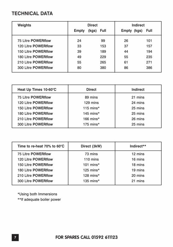
TECHNICAL DATA
Weights Direct IndirectEmpty (kgs) Full Empty (kgs) Full
75 Litre POWERflow 24 99 26 101120 Litre POWERflow 33 153 37 157150 Litre POWERflow 39 189 44 194180 Litre POWERflow 49 229 55 235210 Litre POWERflow 55 265 61 271300 Litre POWERflow 80 380 86 386
Heat Up Times 10-60°C Direct Indirect
75 Litre POWERflow 89 mins 21 mins120 Litre POWERflow 129 mins 24 mins150 Litre POWERflow 115 mins* 25 mins180 Litre POWERflow 145 mins* 25 mins210 Litre POWERflow 166 mins* 26 mins300 Litre POWERflow 175 mins* 25 mins
Time to re-heat 70% to 60°C Direct (3kW) Indirect**
75 Litre POWERflow 73 mins 12 mins120 Litre POWERflow 110 mins 16 mins150 Litre POWERflow 101 mins* 18 mins180 Litre POWERflow 125 mins* 19 mins210 Litre POWERflow 128 mins* 20 mins300 Litre POWERflow 135 mins* 21 mins
*Using both Immersions**If adequate boiler power
8FOR SPARES CALL 01592 611123
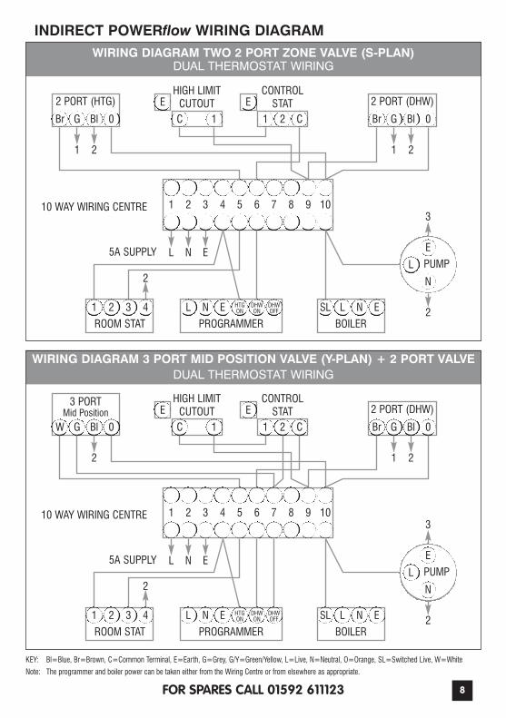
WIRING DIAGRAM TWO 2 PORT ZONE VALVE (S-PLAN)DUAL THERMOSTAT WIRING
INDIRECT POWERflow WIRING DIAGRAM
2 PORT (HTG)HIGH LIMIT
CUTOUTCONTROL
STAT 2 PORT (DHW)
Br G Bl C
E E
1 1 2 C GBr Bl 0
1
0
10 WAY WIRING CENTRE 1 2 3 4 5 6 7 8 9 10
1 2 3 4
ROOM STAT
L N HTGON
DHWON
DHWOFF
PROGRAMMER
LSL N
BOILER
L
N
PUMP5A SUPPLY
KEY: Bl=Blue, Br=Brown, C=Common Terminal, E=Earth, G=Grey, G/Y=Green/Yellow, L=Live, N=Neutral, O=Orange, SL=Switched Live, W=White
Note: The programmer and boiler power can be taken either from the Wiring Centre or from elsewhere as appropriate.
EE
E
3 PORT Mid Position
HIGH LIMITCUTOUT
CONTROLSTAT 2 PORT (DHW)
W G Bl C
E E
1 1 2 C GBr Bl 0
2 1 2
0
10 WAY WIRING CENTRE 1 2
L N
3 4 5 6 7 8 9 10
1 2 3 4
2
ROOM STAT
L N HTGON
DHWON
DHWOFF
PROGRAMMER
LSL N
BOILER
L
N
3
2
PUMP5A SUPPLY E
2 1 2
L N
2
3
2
E
EE
E
WIRING DIAGRAM 3 PORT MID POSITION VALVE (Y-PLAN) + 2 PORT VALVEDUAL THERMOSTAT WIRING
9 FOR SPARES CALL 01592 611123
10FOR SPARES CALL 01592 611123
DATE SERVICED BY COMMENTS
ANNUAL SERVICE RECORDIMPORTANT - Failure to install the cylinder correctly and maintainthis record accurately, will invalidate the manufacturer’s warranty.
McDONALD ENGINEERSHOT WATER SYSTEMSFLEMINGTON ROAD, QUEENSWAY INDUSTRIAL ESTATE, GLENROTHES FIFE KY7 5QFTel : 01592 611123 Fax : 01592 611166Email : [email protected] Internet : www.mcdonald-engineers.com
SOLAR COILSThe cylinder should be installed according to the standard POWERflow instructions.
Single Coil Solar POWERflowThe Dual Thermostat and 2 Port Motorised Zone Valve should be installed and connected asper the standard installation and wiring instructions. The Motorised Zone Valve may beomitted, if the high limit thermostat is wired so as to cut power to the solar pump, in the eventof an overheat situation. Reference should be made to the solar equipment instructions.
Dual Coil Solar The upper Primary Coil, which is linked to a boiler, should be wired as per our standard wiringinstructions on page 8. The lower Solar Coil should be wired as per the above instructions forSingle Coil Solar . Reference should be made to the solar equipment instructions.
HEATPUMP COILSCertain Heatpumps cannot physically exceed a 60ºC flow temperature and as such may notrequire a Motorised Zone Valve, or have alternative methods of control. Consult their installation instructions.
MULTIPLE CYLINDERSWhere 2 or more cylinders are installed together, please contact our technical department, foradvice on the correct procedures - 01592 611123.
MAINTENANCEAs per the instruction booklet and any requirements that the Solar Equipment dictates.
REF:09/11