Embed Size (px)
Citation preview
Paul A. Lagace © 2001
MIT - 16.20 Fall, 2002
Paul A. Lagace, Ph.D.Professor of Aeronautics & Astronautics
and Engineering Systems
Unit 14Behavior of General (including
Unsymmetric Cross-section) BeamsReadings:Rivello 7.1 - 7.5, 7.7, 7.8T & G 126
Unit 14 - 2Paul A. Lagace © 2001
MIT - 16.20 Fall, 2002
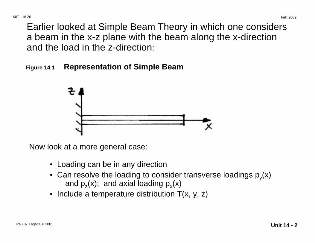
Earlier looked at Simple Beam Theory in which one considersa beam in the x-z plane with the beam along the x-directionand the load in the z-direction:
Figure 14.1 Representation of Simple Beam
• Loading can be in any direction• Can resolve the loading to consider transverse loadings py(x) and pz(x); and axial loading px(x)• Include a temperature distribution T(x, y, z)
Now look at a more general case:
Unit 14 - 3Paul A. Lagace © 2001
MIT - 16.20 Fall, 2002
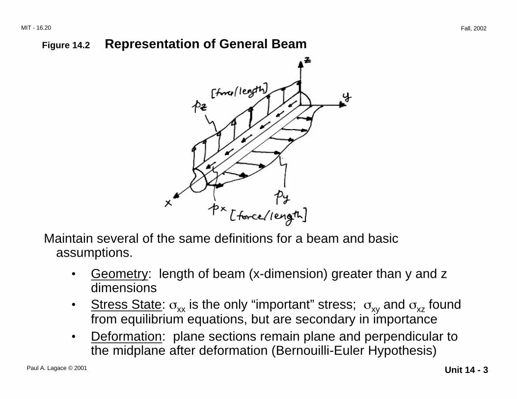
Figure 14.2 Representation of General Beam
Maintain several of the same definitions for a beam and basicassumptions.
• Geometry: length of beam (x-dimension) greater than y and zdimensions
• Stress State: σxx is the only “important” stress; σxy and σxz foundfrom equilibrium equations, but are secondary in importance
• Deformation: plane sections remain plane and perpendicular tothe midplane after deformation (Bernouilli-Euler Hypothesis)
Unit 14 - 4Paul A. Lagace © 2001
MIT - 16.20 Fall, 2002
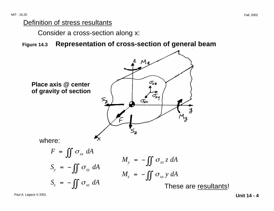
Definition of stress resultants
Consider a cross-section along x:
Figure 14.3 Representation of cross-section of general beam
Place axis @ centerof gravity of section
where:
These are resultants!S dAz xz= − ∫∫ σ
F dAxx= ∫∫ σ
S dAy xy= − ∫∫ σM z dAy xx= − ∫∫ σ
M y dAz xx= − ∫∫ σ
Unit 14 - 5Paul A. Lagace © 2001
MIT - 16.20 Fall, 2002
The values of these resultants are found from statics in terms of theloading px, py, pz, and applying the boundary conditions of the problem
Deformation
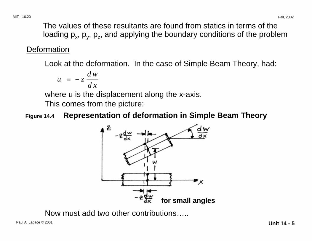
Look at the deformation. In the case of Simple Beam Theory, had:
u zd w
d x= −
where u is the displacement along the x-axis.
Now must add two other contributions…..
Figure 14.4 Representation of deformation in Simple Beam TheoryThis comes from the picture:
for small angles
Unit 14 - 6Paul A. Lagace © 2001
MIT - 16.20 Fall, 2002
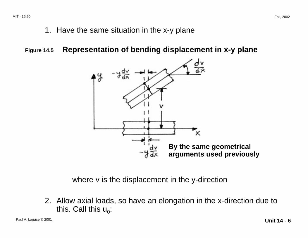
1. Have the same situation in the x-y plane
Figure 14.5 Representation of bending displacement in x-y plane
where v is the displacement in the y-direction
2. Allow axial loads, so have an elongation in the x-direction due tothis. Call this u0:
By the same geometricalarguments used previously
Unit 14 - 7Paul A. Lagace © 2001
MIT - 16.20 Fall, 2002
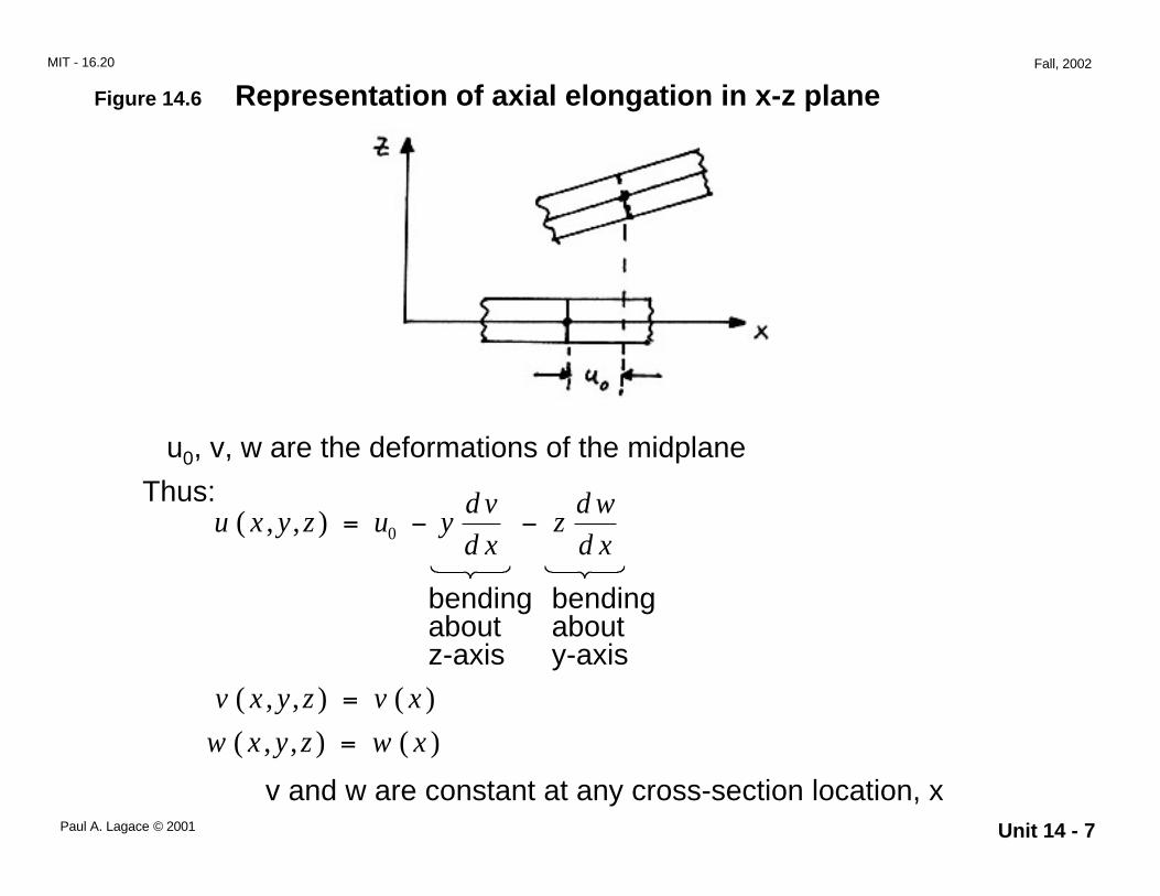
Figure 14.6 Representation of axial elongation in x-z plane
u0, v, w are the deformations of the midplane
Thus:u x y z u y
d v
d xz
d w
d x( , , ) = − −0
bendingaboutz-axis
bendingabouty-axis
v x y z v x( , , ) ( )=
w x y z w x( , , ) ( )=
v and w are constant at any cross-section location, x

Unit 14 - 8Paul A. Lagace © 2001
MIT - 16.20 Fall, 2002
Stress and Strain
From the strain-displacement relation, get:
ε∂∂xx
u
x
d u
dxy
d v
dxz
d w
dx= = + −
+ −
0
2
2
2
2
(these become total derivatives as there is novariation of the displacement in y and z)
for functional ease, write:
fd u
d x10=
fd v
d x2
2
2= −
fd w
d x3
2
2= −
Caution: Rivello uses C1, C2, C3. These are not constants,so use fi ⇒ fi(x) (functions of x)
Unit 14 - 9Paul A. Lagace © 2001
MIT - 16.20 Fall, 2002
Thus:ε xx f f y f z= + +1 2 3
Then use this in the stress-strain equation (orthotropic or “lower”):
εσ
αxxxx
ET= + ∆
(include temperature effects)
Note: “ignore” thermal strains in y and z. These are of“secondary” importance.
Thus:
σ ε αxx xxE E T= − ∆
and using the expression for εx:
σ αxx E f f y f z E T= + +( ) −1 2 3 ∆
Can place this expression into the expression for the resultants(force and moment) to get:
Unit 14 - 10Paul A. Lagace © 2001
MIT - 16.20 Fall, 2002
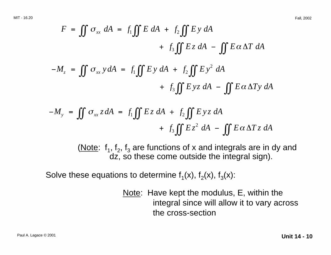
F dA f E dA f E y dAxx= = +∫∫ ∫∫ ∫∫σ 1 2
+ −∫∫ ∫∫f E z dA E T dA3 α ∆
− = = +∫∫ ∫∫ ∫∫M y dA f E y dA f E y dAz xxσ 1 22
+ −∫∫ ∫∫f E yz dA E Ty dA3 α ∆
− = = +∫∫ ∫∫ ∫∫M z dA f E z dA f E y z dAy xxσ 1 2
+ −∫∫ ∫∫f E z dA E T z dA32 α ∆
(Note: f1, f2, f3 are functions of x and integrals are in dy anddz, so these come outside the integral sign).
Solve these equations to determine f1(x), f2(x), f3(x):
Note: Have kept the modulus, E, within theintegral since will allow it to vary acrossthe cross-section
Unit 14 - 11Paul A. Lagace © 2001
MIT - 16.20 Fall, 2002
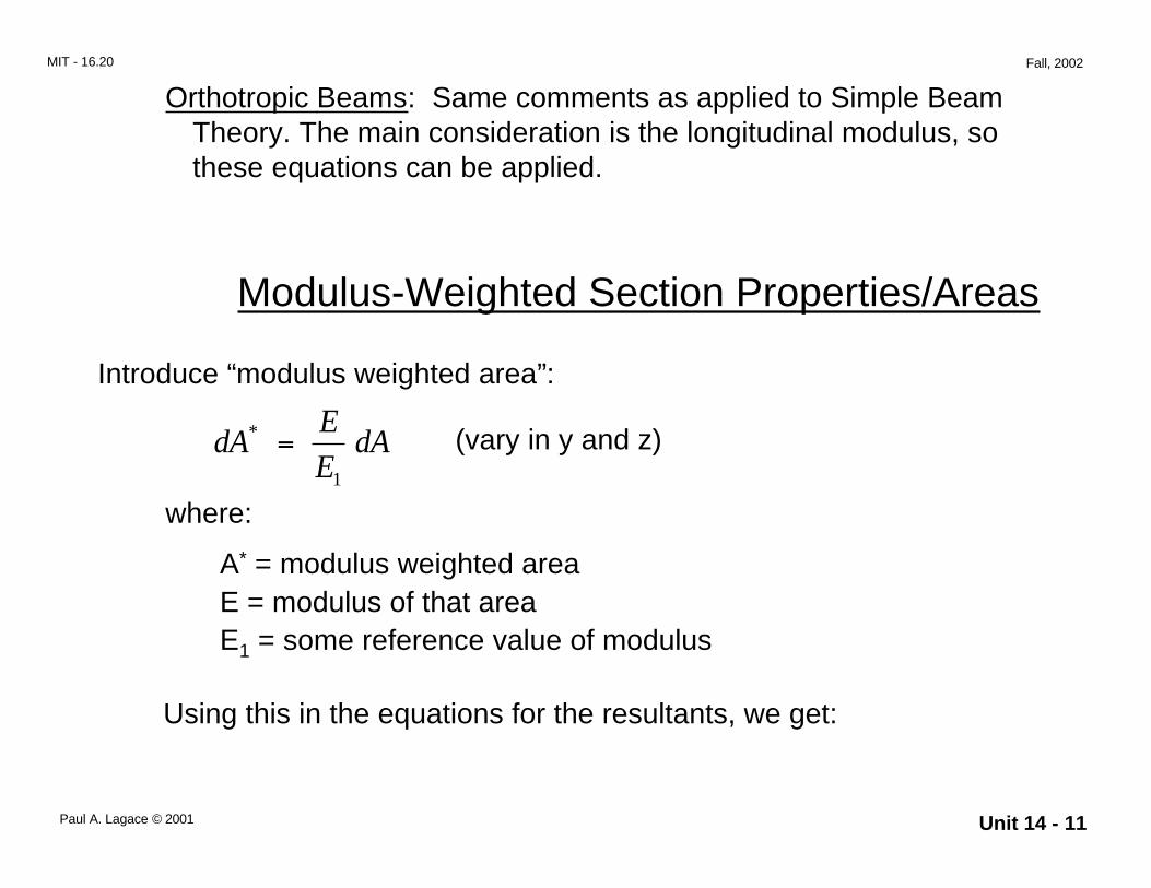
Orthotropic Beams: Same comments as applied to Simple BeamTheory. The main consideration is the longitudinal modulus, sothese equations can be applied.
Using this in the equations for the resultants, we get:
Modulus-Weighted Section Properties/Areas
Introduce “modulus weighted area”:
dAE
EdA* =
1
(vary in y and z)
where:
A* = modulus weighted areaE = modulus of that areaE1 = some reference value of modulus
Unit 14 - 12Paul A. Lagace © 2001
MIT - 16.20 Fall, 2002
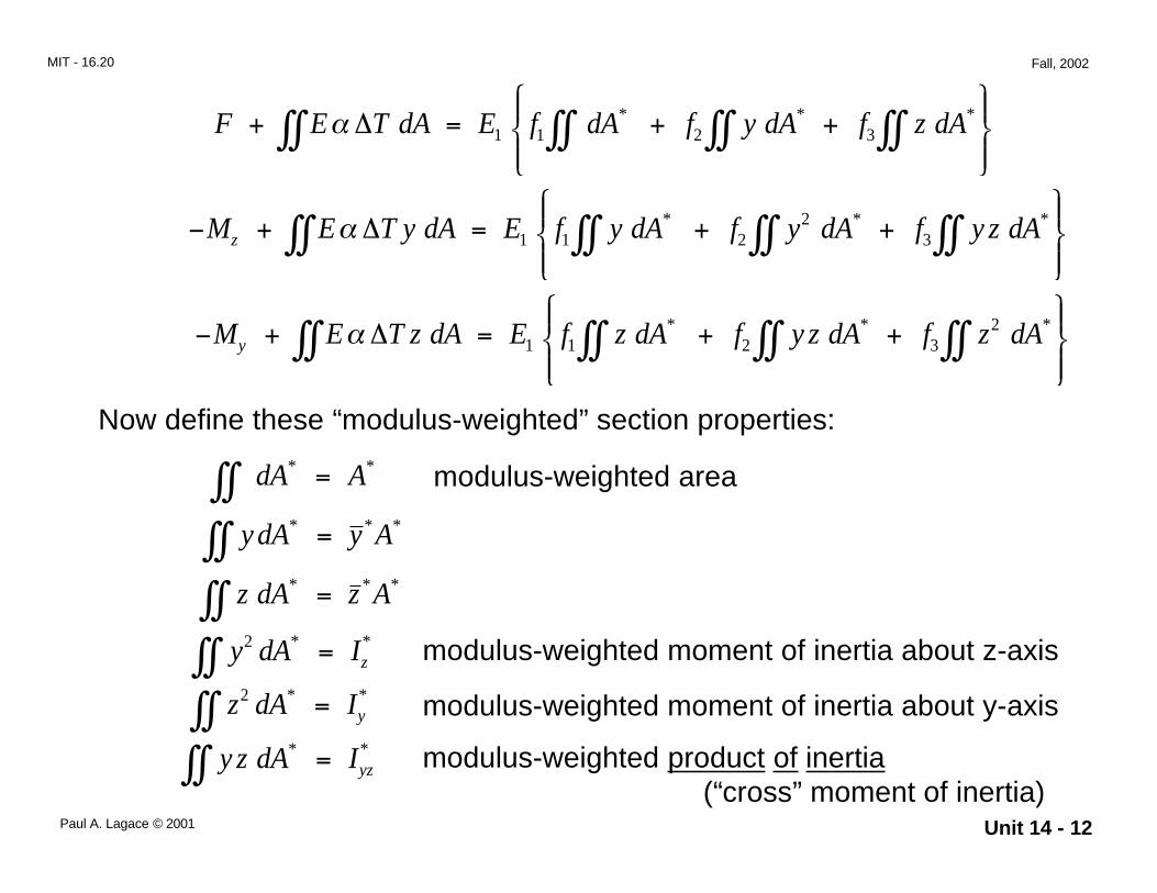
F E T dA E f dA f y dA f z dA+ = + +
∫∫ ∫∫ ∫∫ ∫∫α ∆ 1 1 2 3
* * *
− + = + +
∫∫ ∫∫ ∫∫ ∫∫M E T y dA E f y dA f y dA f y z dAz α ∆ 1 1 2
23
* * *
− + = + +
∫∫ ∫∫ ∫∫ ∫∫M E T z dA E f z dA f y z dA f z dAy α ∆ 1 1 2 3
2* * *
Now define these “modulus-weighted” section properties:
modulus-weighted areadA A* *∫∫ =
y dA y A* * *∫∫ =
z dA z A* * *∫∫ =
y dA Iz2 *∫∫ = *
z dA Iy2 *∫∫ = *
y z dA Iyz*∫∫ = *
modulus-weighted moment of inertia about z-axis
modulus-weighted moment of inertia about y-axis
modulus-weighted product of inertia(“cross” moment of inertia)
Unit 14 - 13Paul A. Lagace © 2001
MIT - 16.20 Fall, 2002
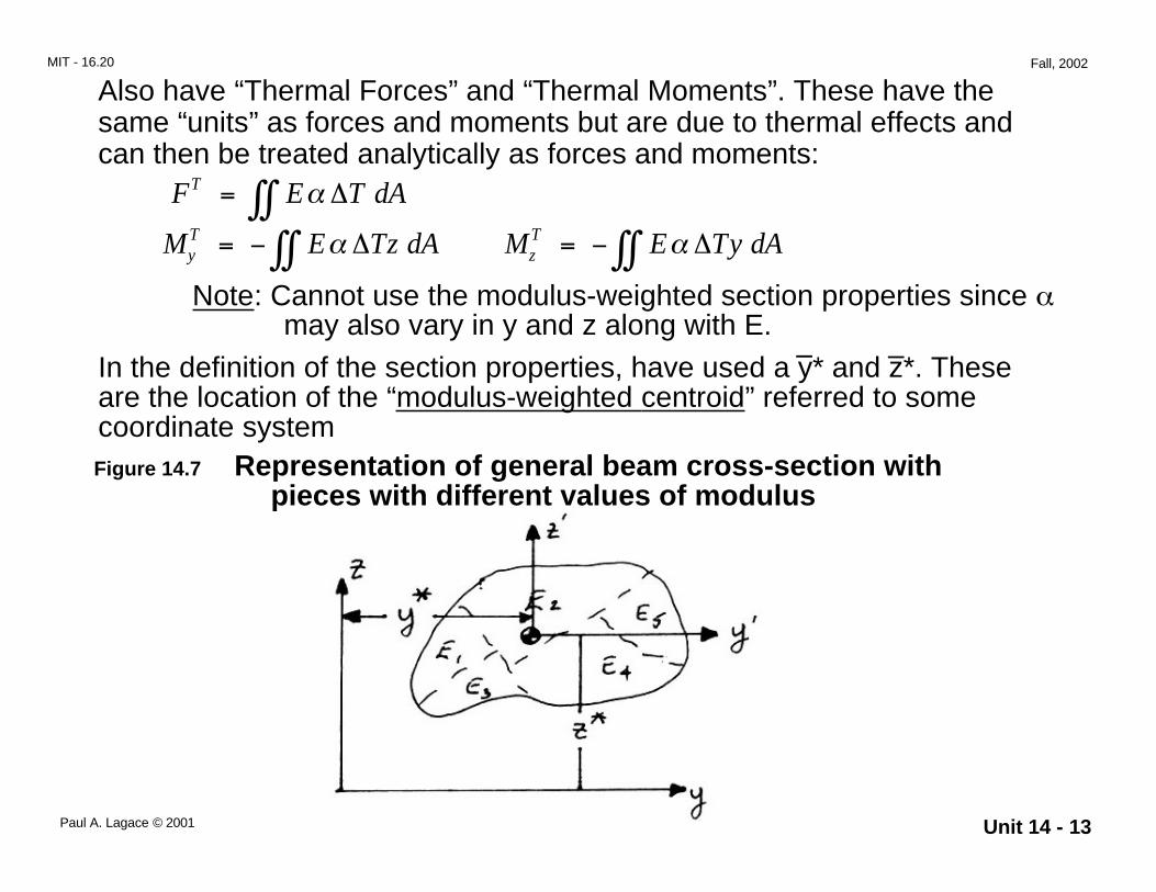
Also have “Thermal Forces” and “Thermal Moments”. These have thesame “units” as forces and moments but are due to thermal effects andcan then be treated analytically as forces and moments:
F E T dAT = ∫∫ α ∆
M E Tz dAyT = − ∫∫ α ∆ M E Ty dAz
T = − ∫∫ α ∆
Note: Cannot use the modulus-weighted section properties since αmay also vary in y and z along with E.
Figure 14.7 Representation of general beam cross-section with pieces with different values of modulus
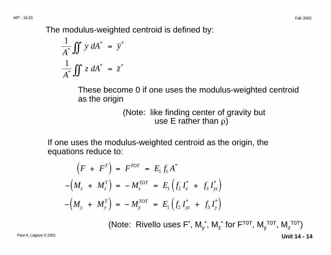
In the definition of the section properties, have used a y* and z*. Theseare the location of the “modulus-weighted centroid” referred to somecoordinate system
– –
Unit 14 - 14Paul A. Lagace © 2001
MIT - 16.20 Fall, 2002
1A
y dA y** *∫∫ =
1A
z dA z** *∫∫ =
These become 0 if one uses the modulus-weighted centroidas the origin
(Note: like finding center of gravity butuse E rather than ρ)
If one uses the modulus-weighted centroid as the origin, theequations reduce to:
F F F E f AT TOT+( ) = = 1 1*
− +( ) = − = +( )M M M E f I f Iz zT
zTOT
z yz1 2 3* *
− +( ) = − = +( )M M M E f I f Iy yT
yTOT
yz y1 2 3* *
(Note: Rivello uses F*, My*, Mz
* for FT0T, MyT0T, Mz
T0T)
The modulus-weighted centroid is defined by:
Unit 14 - 15Paul A. Lagace © 2001
MIT - 16.20 Fall, 2002
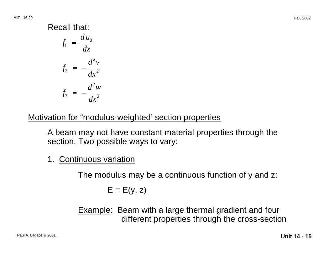
Recall that:
fd u
dx10=
fd v
dx2
2
2= −
fd w
dx3
2
2= −
Motivation for “modulus-weighted’ section properties
A beam may not have constant material properties through thesection. Two possible ways to vary:
1. Continuous variation
The modulus may be a continuous function of y and z:
E = E(y, z)
Example: Beam with a large thermal gradient and fourdifferent properties through the cross-section

Unit 14 - 16Paul A. Lagace © 2001
MIT - 16.20 Fall, 2002
A composite beam which, although it’s made of the samematerial, has different modulus, Ex, through-the-thickness asthe fiber orientation varies from ply to ply.
Figure 14.8 Representation of cross-section of laminated beam with different modulus values through the thickness
(symmetric)
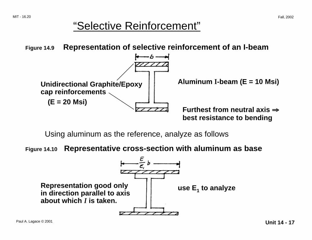
A method of putting material to its best use is called:
2. Stepwise variation
Unit 14 - 17Paul A. Lagace © 2001
MIT - 16.20 Fall, 2002
Figure 14.9 Representation of selective reinforcement of an I-beam
Aluminum I-beam (E = 10 Msi)Unidirectional Graphite/Epoxycap reinforcements
Furthest from neutral axis ⇒⇒⇒⇒best resistance to bending
(E = 20 Msi)
Using aluminum as the reference, analyze as follows
Figure 14.10 Representative cross-section with aluminum as base
use E1 to analyze
“Selective Reinforcement”
Representation good onlyin direction parallel to axisabout which I is taken.
Unit 14 - 18Paul A. Lagace © 2001
MIT - 16.20 Fall, 2002
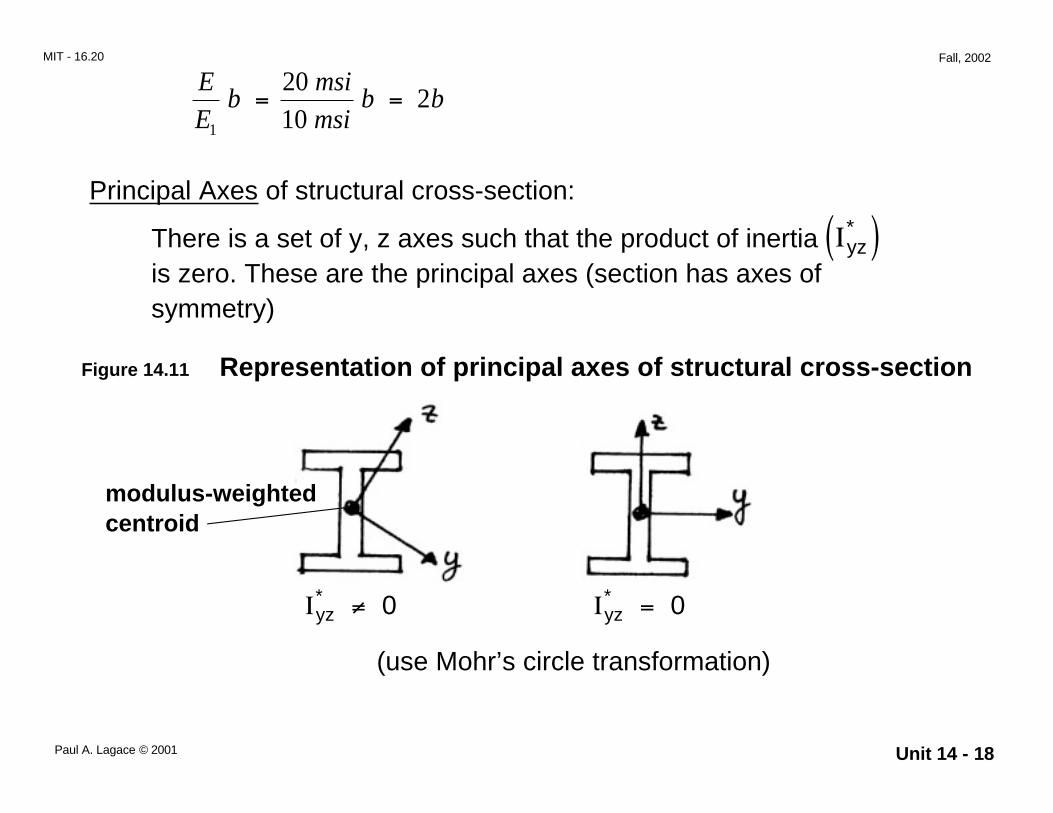
E
Eb
msi
msib b
1
2010
2= =
Principal Axes of structural cross-section:
There is a set of y, z axes such that the product of inertiais zero. These are the principal axes (section has axes ofsymmetry)
Ιyz*( )
Figure 14.11 Representation of principal axes of structural cross-section
modulus-weightedcentroid
Ιyz* ≠ 0 Ιyz
* = 0
(use Mohr’s circle transformation)
Unit 14 - 19Paul A. Lagace © 2001
MIT - 16.20 Fall, 2002
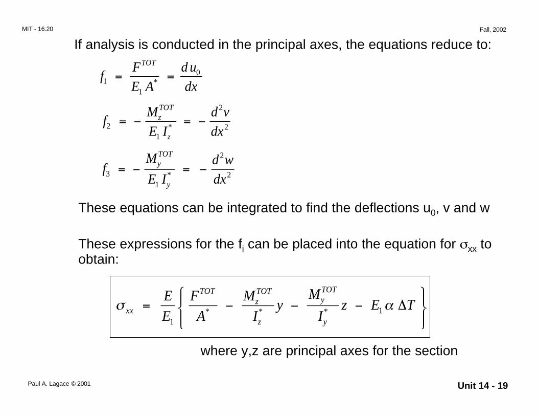
fF
E A
d u
dx
TOT
11
0= =*
fM
E I
d v
dxzTOT
z2
1
2
2= − = −*
fM
E I
d w
dxyTOT
y3
1
2
2= − = −*
These equations can be integrated to find the deflections u0, v and w
These expressions for the fi can be placed into the equation for σxx toobtain:
σ αxx
TOTzTOT
z
yTOT
y
E
E
F
A
M
Iy
M
Iz E T= − − −
11* * * ∆
where y,z are principal axes for the section
If analysis is conducted in the principal axes, the equations reduce to:
Unit 14 - 20Paul A. Lagace © 2001
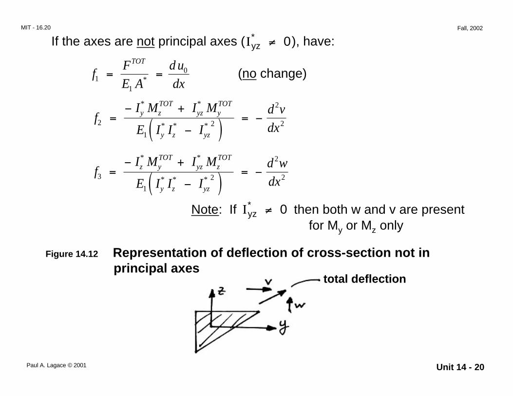
MIT - 16.20 Fall, 2002
(no change)fF
E A
d u
dx
TOT
11
0= =*
fI M I M
E I I I
d v
dxy z
TOTyz y
TOT
y z yz
2
1
2
2
2=− +
−( )= −
* *
* * *
fI M I M
E I I I
d w
dxz y
TOTyz z
TOT
y z yz
3
1
2
2
2=− +
−( )= −
* *
* * *
Note: If then both w and v are present for My or Mz only
Ιyz* ≠ 0
Figure 14.12 Representation of deflection of cross-section not in principal axes
total deflection
If the axes are not principal axes ( ), have:Ιyz* ≠ 0
Unit 14 - 21Paul A. Lagace © 2001
MIT - 16.20 Fall, 2002
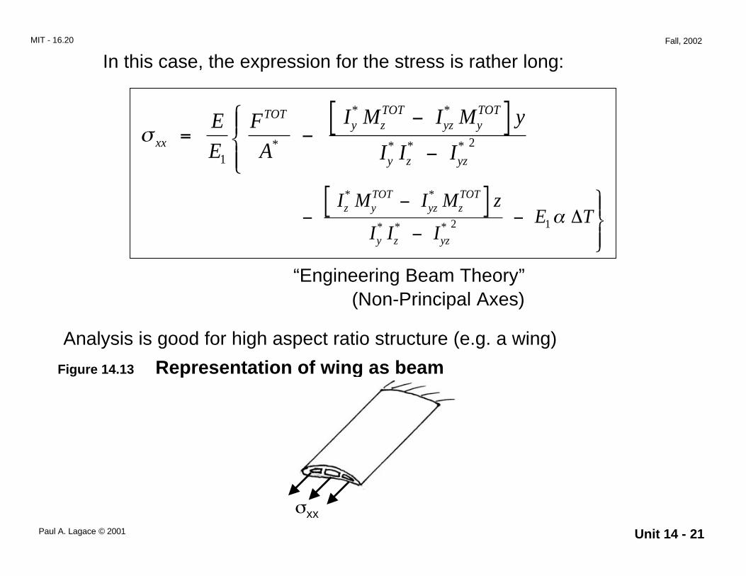
In this case, the expression for the stress is rather long:
σ xx
TOTy z
TOTyz y
TOT
y z yz
E
E
F
A
I M I M y
I I I= −
−[ ]−
12*
* *
* * *
−−[ ]−
−
I M I M z
I I IE T
z yTOT
yz zTOT
y z yz
* *
* * * 2 1α ∆
“Engineering Beam Theory”(Non-Principal Axes)
Analysis is good for high aspect ratio structure (e.g. a wing)
Figure 14.13 Representation of wing as beam
σxx
Unit 14 - 22Paul A. Lagace © 2001
MIT - 16.20 Fall, 2002
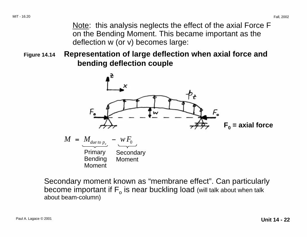
Note: this analysis neglects the effect of the axial Force Fon the Bending Moment. This became important as thedeflection w (or v) becomes large:
Figure 14.14 Representation of large deflection when axial force and bending deflection couple
F0 = axial force
PrimaryBendingMoment
SecondaryMoment
Secondary moment known as “membrane effect”. Can particularlybecome important if Fo is near buckling load (will talk about when talkabout beam-column)
M M w Fdue to pz= − 0

Unit 14 - 23Paul A. Lagace © 2001
MIT - 16.20 Fall, 2002
Shear Stresses
The shear stresses (σxy and σxz) can be obtained from the equilibriumequations:
∂σ
∂∂σ∂
∂σ∂
xy xz xx
y z x+ = −
∂σ
∂xy
x= 0
∂σ∂
xz
x= 0
Figure 14.15 Representation of cross-section of general beam
Unit 14 - 24Paul A. Lagace © 2001
MIT - 16.20 Fall, 2002
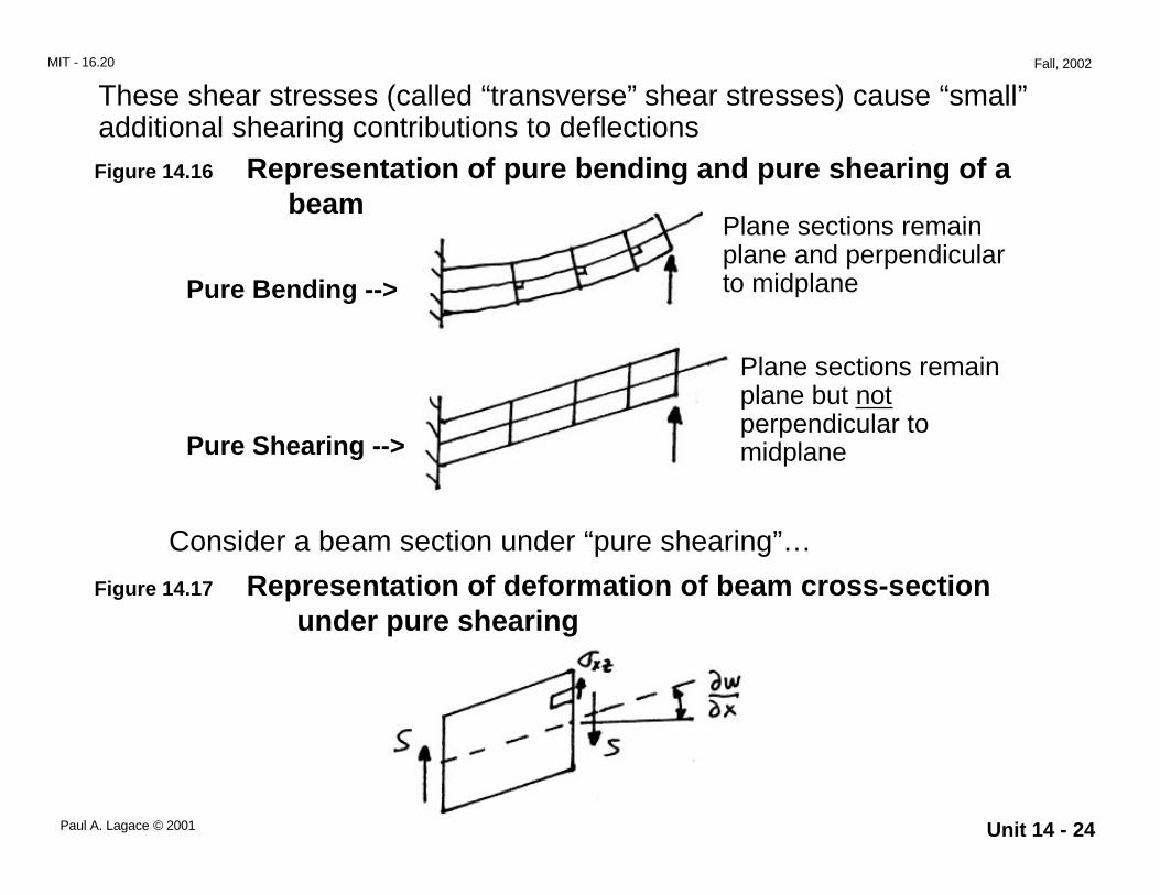
These shear stresses (called “transverse” shear stresses) cause “small”additional shearing contributions to deflectionsFigure 14.16 Representation of pure bending and pure shearing of a beam
Plane sections remainplane and perpendicularto midplane
Plane sections remainplane but notperpendicular tomidplane
Pure Bending -->
Pure Shearing -->
Consider a beam section under “pure shearing”…
Figure 14.17 Representation of deformation of beam cross-section under pure shearing
Unit 14 - 25Paul A. Lagace © 2001
MIT - 16.20 Fall, 2002
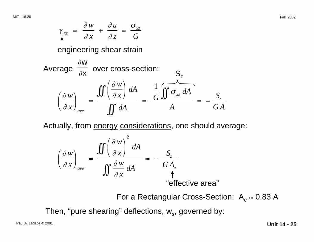
γ∂∂
∂∂
σxz
xzw
x
u
z G= + =
engineering shear strain
Average over cross-section:∂∂wx
∂∂
∂∂ σw
x
w
xdA
dAG
dA
A
S
G Aave
xzz
=
= = −∫∫
∫∫∫∫
1
Actually, from energy considerations, one should average:
∂∂
∂∂∂∂
w
x
w
xdA
w
xdA
S
G Aave
z
e
=
≈ −∫∫
∫∫
2
“effective area”
For a Rectangular Cross-Section: Ae ≈ 0.83 A
Then, “pure shearing” deflections, ws, governed by:
Sz
Unit 14 - 26Paul A. Lagace © 2001
MIT - 16.20 Fall, 2002
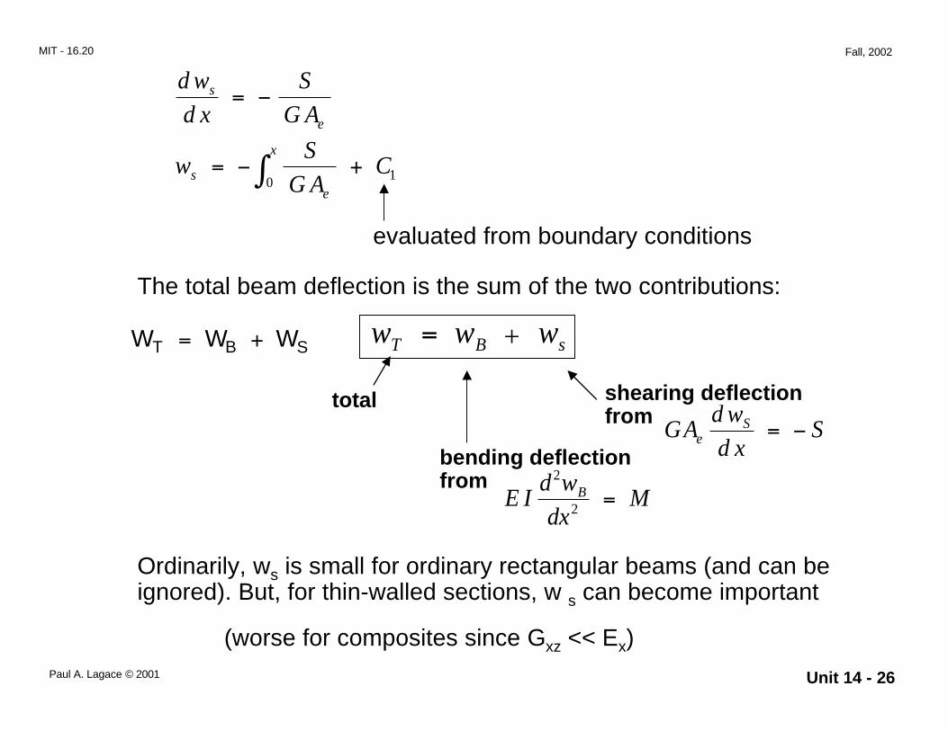
w w wT B s= −
d w
d x
S
G As
e
= −
evaluated from boundary conditions
wS
G ACs
e
x= − +∫0 1
The total beam deflection is the sum of the two contributions:
total
bending deflectionfrom
shearing deflectionfrom
E Id w
dxMB
2
2 =
GAd w
d xSe
S = −
Ordinarily, ws is small for ordinary rectangular beams (and can beignored). But, for thin-walled sections, w s can become important
(worse for composites since Gxz << Ex)
W W WT B S = + +

Unit 14 - 27Paul A. Lagace © 2001
MIT - 16.20 Fall, 2002
In addition to “bending” and “shearing”, the section may also twistthrough an angle α
Figure 14.18 Representation of twisting of beam cross-section
However, there exists a Shear Center for every section. If the loadis applied at the shear center, the section translates but does nottwist.
(Note: shear center not necessarily center of gravity orcentroid)
Unit 14 - 28Paul A. Lagace © 2001
MIT - 16.20 Fall, 2002
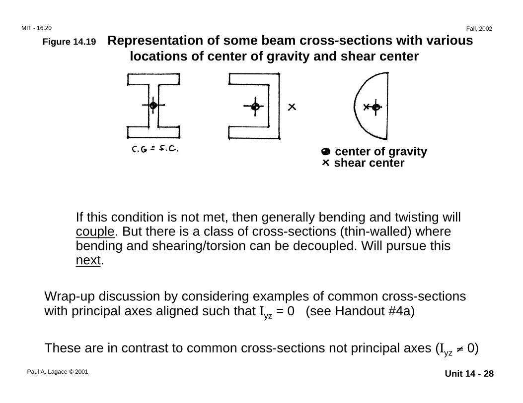
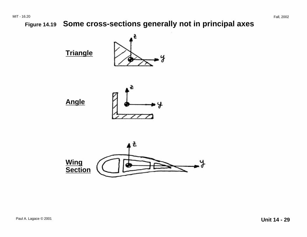
Figure 14.19 Representation of some beam cross-sections with various locations of center of gravity and shear center
If this condition is not met, then generally bending and twisting willcouple. But there is a class of cross-sections (thin-walled) wherebending and shearing/torsion can be decoupled. Will pursue thisnext.
Wrap-up discussion by considering examples of common cross-sectionswith principal axes aligned such that Iyz = 0 (see Handout #4a)
These are in contrast to common cross-sections not principal axes (Iyz ≠ 0)
center of gravityshear center
Unit 14 - 29Paul A. Lagace © 2001
MIT - 16.20 Fall, 2002
Figure 14.19 Some cross-sections generally not in principal axes
Triangle
Angle
WingSection
Unit 14 - 30Paul A. Lagace © 2001
MIT - 16.20 Fall, 2002
--> Finally
What are the limitations to the Engineering Beam Theory as developed?
• Shear deflections small (can get first order cut at this)• No twisting (load along shear center) -- otherwise torsion and
bending couple• Deflections small
o – No moment due to axial load (Pw)o – Angles small such that sinφ ≈ φ• --> will consider next order effect when discuss buckling and
postbuckling• --> consideration will stiffen (membrane effect) structure
• Did not consider εzz (Poisson’s effect)


![Residual Curing Stresses in Thin [0/90] Unsymmetric Composite Plates](https://img.pdfslide.us/doc/110x75/5681420a550346895dadfa25/residual-curing-stresses-in-thin-090-unsymmetric-composite-plates.jpg)
