Embed Size (px)
Citation preview
1
ABSTRACT
The presented paper describes experimental investigations ofrotating cavitation in centrifugal pump impellers of low specificspeed with different geometries, all designed for the sameoperating point. All impellers are showing rotating cavitation ofa very similar mechanism over a wide range of part load flowrates.One focus of the investigations was the onset of rotatingcavitation revealing an almost constant value σ/2α (cavitationnumber in relation to blade incidence angle) for each singleimpeller but a significant change between the different impellergeometries. The second part describes detailed unsteady flowfield results obtained during rotating cavitation at the passageinlet as well as the outlet area. These results are giving a verygood impression about the development of a cavity attached toone blade and their influence to the adjacent passage. It is shownthat the interaction mechanism is mainly driven by the inducedvelocity distribution of the cavity affecting the flow direction(incidence angle) of the following blade. Furthermore the cavityseparation as a typical vortex shedding effect and the subsequentdisturbance of the entire flow within the passage caused by thevortex and its assigned wake was observed.Finally the still remarkable influence of the vortex relateddisturbance at the passage outlet without any noticeable vaporcontent is shown with regards to the significant „creeping headdrop“ of the pump.
NOMENCLATUREb passage width
d diameter
g gravity
H head
n impeller rotating speed
ns specific speed 333*n* 1/2/(g*H)3/4
NPSH net positive suction head (ps-pv) /(ρg)+cs2/(2g)
p static pressure
pv vapor pressure
s blade thickness
U upstream mean velocity
volume flow
w impeller relative velocity
z number of blades
incidence angle
blade angle
wave-length
density
cavitation number 2*(p1-pv) / ρU2
1 inlet
2 outlet
3% 3% pump head drop
D design point
IC incipient cavitation
rel design-point related
loc local
INTRODUCTION
Rotating cavitation as a two-phase instability phenomenonmeans major impacts on performance and reliability of hydraulicpumps whenever it occurs. First discovered in inducers of highspeed rocket turbopumps (Ariane-V and H-II) it has become awell known problem which has been analyzed by experimental[10] and theoretical methods [11], [13], [6]. The first observationof a similar effect in a centrifugal pump impeller was reported in[1]. During a project hosted by the DFG (Deutsche
V·
V·
αβλρσ
UNSTEADY PIV FLOW FIELD ANALYSISOF A CENTRIFUGAL PUMP IMPELLER UNDER ROTATING CAVITATION
Fifth International Symposium on Cavitation (Cav 2003)Osaka, Japan, November 1 - 4, 2003
Cav03-OS-6-005
Jens FriedrichsMTU Maintenance Hannover GmbH
Münchner Straße 3130855 Langenhagen, Germany
E-Mail: [email protected]
Günter KosynaPfleiderer-Institut für Strömungsmaschinen
TU Braunschweig, Langer Kamp 638106 Braunschweig, Germany
E-Mail: [email protected]
2
Forschungsemeinschaft) and carried out by the Laboratory forTurbomachinery and Fluid Power (Technical University ofDarmstadt) and the Pfleiderer-Institute (Technical University ofBraunschweig) with the focus on cavitation phenomena and theirerosive impacts the occurrence of rotating cavitation was againobserved and confirmed in a centrifugal pump impeller of lowspecific speed [2]. The first visual investigations we performedto gain information about the phenomenon itself and its relatedeffects on the overall pump performance.The obtained results are showing a strong similarity to theturbopump phenomenon in terms of a „creeping head drop“during rotating cavitation as well as a constant parameter σ/2αdescribing the onset of rotating cavitation for all operating pointsof one impeller geometry [3]. In addition, those investigationsrevealed a strong fluctuation of the passage incidence angleduring rotating cavitation which was considered to be one of thedriving forces leading to the rotating character of the instability.In order to get a better understanding of the local behavior and
mechanisms of rotating cavitation a detailed flow field analysiswas carried out by using a customized PIV (Particle ImageVelocimetry) technique. The results in terms of unsteady flowfield velocity distribution during rotating cavitation allow aninterpretation of the interaction between the cavity and thesurrounding flow field with regards to theoretical analysisperformed on turbopumps, i.e. [6]. In addition to supplement thethesis of the onset of rotating cavitation as an effect driven by thepassage incidence angle two new impellers for the same designpoint but with a different number of blades were used for theinvestigation.
EXPERIMENTAL SETUP
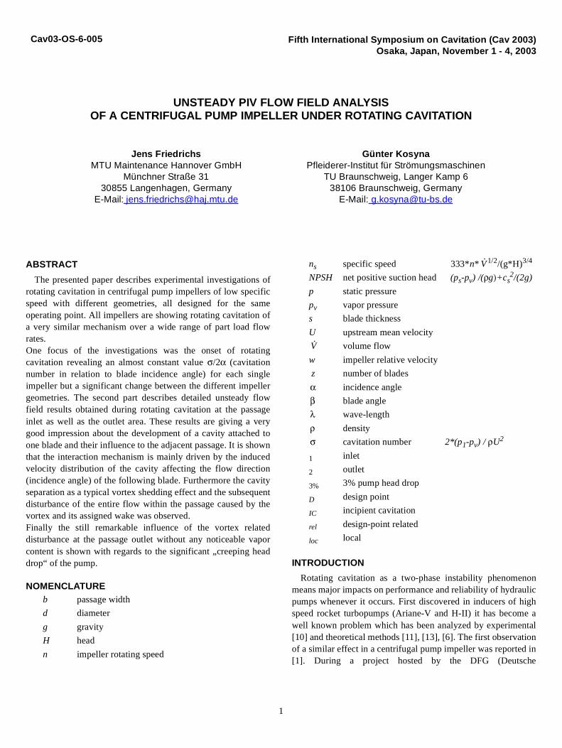
All impellers were tested in closed circuit test rig with variablesystem pressure. A vaneless diffuser was used instead of a voluteto produce a uniform circumferential pressure distribution at theimpeller outlet. The diffuser itself was connected to the upstreamsystem by twelve discharge pipes. Figure 1 shows a cross-sectional view of the radial test pump. To enable a directobservation as well as PIV measurement of the impeller theshroud and also the front casing were made of plexiglas.All impellers are a 2D designs with parallel shroud and hub andblades consisting of two circular arcs each. Having a differentnumber of blades all impellers were designed for the sameoperating point which leads to different outlet angles as well asinlet angels. In table 1 the design parameters of all impellers areshown.
PIV Setup
In addition to the optical results shown in [2] and [3] newexperimental investigations of the unsteady cavitating flow wereperformed using a customized PIV system. Two identical CCDcameras were mounted adjacent to each other; the first one
Impeller A B C
Blade shape 2-circ.-arc 2-circ.-arc 2-circ.-arc
Inlet- d1 260mm 260mm 260mm
Outlet- d2 556mm 556mm 556mm
Inlet angle 17o 19o 20o
Outlet angle 30o 23o 19o
Passage width b 46mm 46mm 46mm
Number of blades z 4 5 6
Specific speed ns 27.5 27.5 27.5
Blade thickness s 13mm 13mm 13mm
Rotating speed n 9Hz 9Hz 9Hz
Table 1: Design parameters of impellers
impeller
plexiglas-casing
shaft
vanelessdiffuser
12 discharge
Figure 1: Cross-sectional view of test pump
diversion-
flow
inlet
pipes
plexiglas-shroud
chamber
∅∅
β1
β2
Laser
Type Nd:Yag
Thickness light-sheet 1.0 - 1.5 mm
Energy of puls 120 mJ
Puls duration 10 ns
Double-puls interval 80 - 120 µs
Camera
Scan size 1280 x 1024 Pixel
Image size 161 x 128 mm
Focal distance 60 mm
Scale-factor 18.829
Processing
Interrogation-area 32 x 32 Pixel
Overlapping 25 %
Subpixel interpolation Low-pass Gaussian
Vector array size 53 x 42
Tabelle 2: PIV setup and signal processing
3
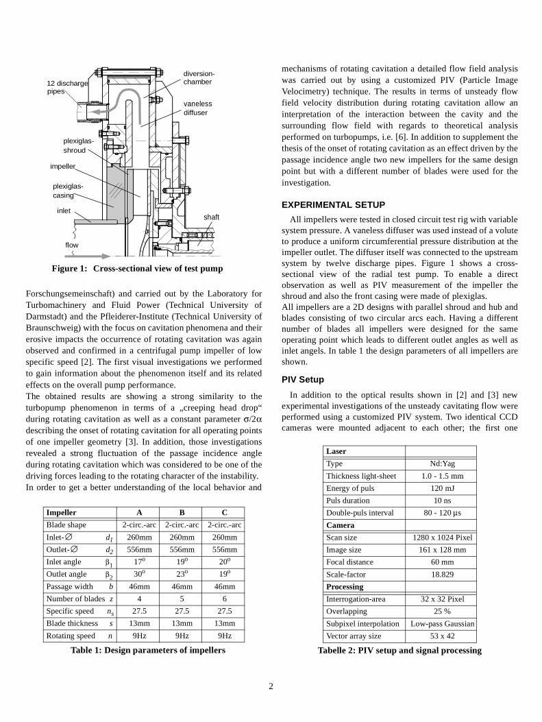
(camera 1) fitted with a low-pass filter and the second one(camera 2) with a band-pass filter. The used seeding particleswere coated with Rhodamin B, a fluorescent material sendingout low frequency light ( ) once it is exposed to laserlight ( ). Since the seeding is carried by the liquidphase of the cavitating flow the low-pass filtered camera 1 isobserving only this liquid phase and it is not disturbed by thebright reflections coming from the vapor/liquid phase transition.On the other hand camera 2 operating with the band-pass filtercan be adjusted to the directly reflected laser light (lower shutter)to obtain images from the unsteady vapor/liquid distribution ofexactly the same state. Both cameras are taking double exposureimages (double laser puls) at the same time.During the following signal processing the images fromcamera 1 are cross-correlated leading to a local displacementvector field of the liquid phase. In parallel one image fromcamera 2 is used to record the vapor/liquid distribution of theflow for the same laser puls. In figure 2 two typical imagesobtained by this method are shown. On the left hand (camera 2)the typical phase distribution of full developed rotationcavitation can be found characterized by a large cavity areaconsisting of multiple phase limits. The same laser puls as it isseen by camera 1 on the right hand: A uniform seedingdistribution can be found within the liquid flow as a majorrequirement for the following cross-correlation withoutdisturbance from the cavity area which appears more as a fadedzone. Table 2 shows the main parameters of the used PIVsystem. In addition to the cross-correlation analysis all flow fieldimages were validated using a moving average validation [7] andfinally transferred from the PIV absolute system into theimpeller relative system:
RESULTS AND DISCUSSION
Overall performance and instability
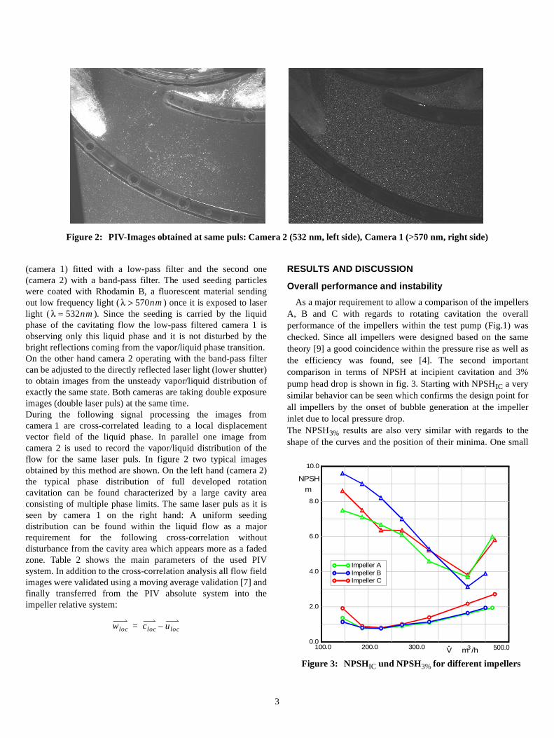
As a major requirement to allow a comparison of the impellersA, B and C with regards to rotating cavitation the overallperformance of the impellers within the test pump (Fig.1) waschecked. Since all impellers were designed based on the sametheory [9] a good coincidence within the pressure rise as well asthe efficiency was found, see [4]. The second importantcomparison in terms of NPSH at incipient cavitation and 3%pump head drop is shown in fig. 3. Starting with NPSHIC a verysimilar behavior can be seen which confirms the design point forall impellers by the onset of bubble generation at the impellerinlet due to local pressure drop.The NPSH3% results are also very similar with regards to theshape of the curves and the position of their minima. One small
λ 570nm>λ 532nm≈
Figure 2: PIV-Images obtained at same puls: Camera 2 (532 nm, left side), Camera 1 (>570 nm, right side)
wloc cloc uloc–=
Figure 3: NPSHIC und NPSH3% for different impellers
100.0 200.0 300.0 500.00.0
2.0
4.0
6.0
8.0
10.0
Impeller AImpeller BImpeller C
V m3/h
NPSH
m

4
difference can be seen within the increase of NPSH3% forimpeller C on both sides of its minimum. Taking into account thesame blade thickness for all impellers the blockage at the inletduring cavitation as the sum of blade and cavity caused blockageis increased for a higher number of blades which explains theobserved behavior.
Focussing on rotating cavitation fig. 4 shows the onset of theinstability for the tested configurations. All impellers areshowing the phenomenon at part load conditions of 66% designflow rate and below. For the 5-bladed impeller (Impeller B) theobservation was already discussed in [2] where also acomparison with a scaled pumps and different leading edgegeometries was shown. In terms of σ/2α both pumps revealedthe beginning of rotating cavitation at the same time.Therefore the conclusion was drawn that rotating cavitation canbe understood as an impeller instability problem which is drivenby the relation of increasing cavity volume (or cavity length) andimpeller incidence angle.By extending the analysis with the results of impeller A and Cthis explanation is completely confirmed. Both new impellersare showing in each case an almost constant onset of rotatingcavitation expressed in σ/2α for all flow rates. But the level isshifted of approximately 0,42 compared to impeller B,downwards for the 4-bladed impeller (Imp. A) and upwards forthe 6-bladed (Imp. C).Since the change of the incidence angle as the differencebetween design point and actual flow angle is the same for allimpellers at the same flow rate, the shift of σ/2α must be causedby a shift of σ meaning the onset of rotating cavitation at adifferent system pressure.From the observation during rotating cavitation it was found thatthe shape of the cavity during onset and fully developed rotatingcavitation is the same for all impellers at the same flow rate,which is also major driven by the described incidence angle.
Therefore the observed shift in σ/2α is not caused by a changedtype of cavitation but by a geometrically similar cavity ofdifferent size.In terms of the interaction between cavity and impeller passagethis can be explained as a larger cavity (lower σ) which isrequired to cause the same instability for impeller A due to itslarger pitch (t) or, on the other hand a smaller cavity (higher σ) tocause the same instability for impeller C with a smaller pitch.
Based on σ/2α = 2,35 as the results for impeller B the shift ofimpeller A and C in fig. 4 is approximately +/- 17%.Transferring the impeller design into a 2-dimensional cascademodel a shift within the pitch of +/- 20% for A and C comparedto B can be found.This means according to the results of [12] and [6] the cavity sizerelated to the pitch of the cascade is the important instabilitycriteria for development of rotating cavitation.
Unsteady flow field at impeller inlet
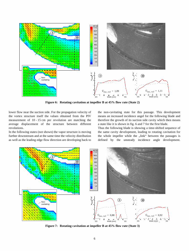
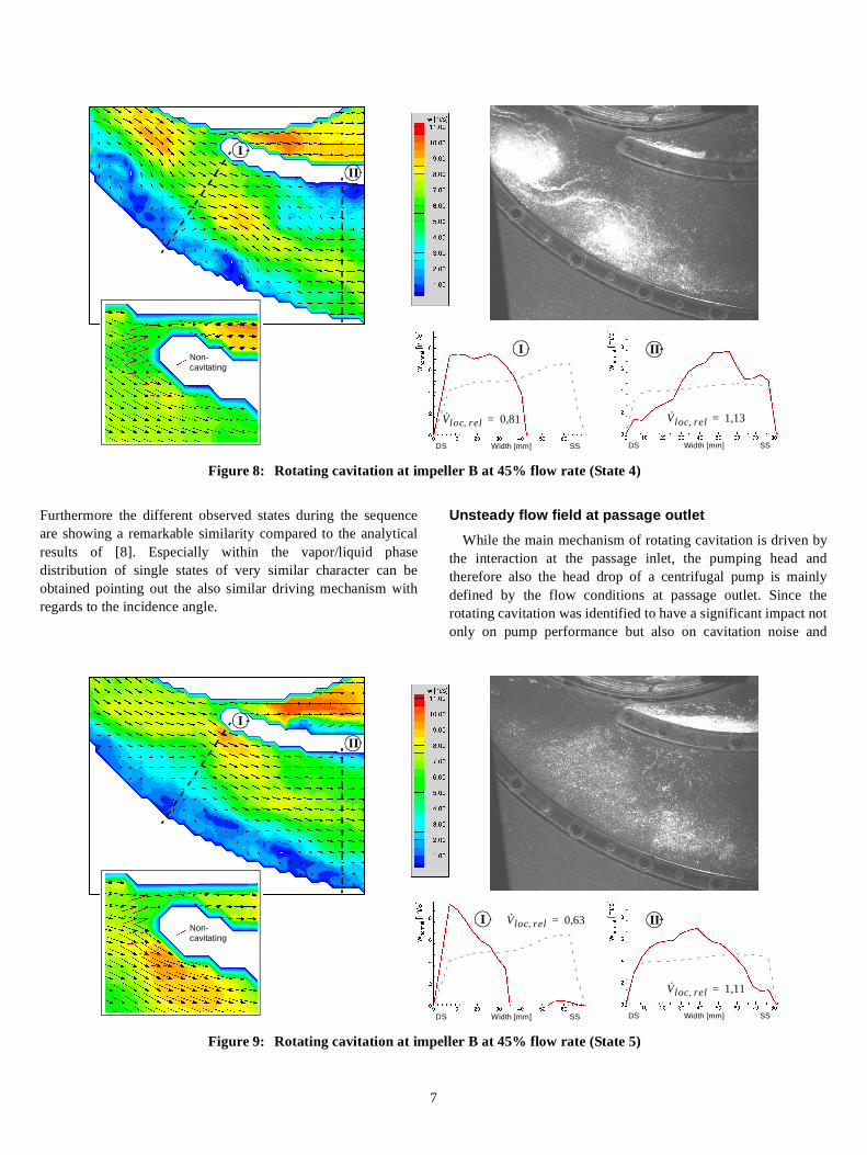
In order to analyze the detailed behavior of the flow in onepassage during a sequence of rotating cavitation fig. 5 to 9 showthe results obtained by using the above described PIV technique.Each figure shows the inlet of the same passage of impeller Bafter different revolutions within the same sequence of rotatingcavitation. In order to allow a most detailed analysis within onesequence of rotating cavitation a operating point of lowpropagation velocity was chosen, in this case approx. 9-10impeller revolutions for a full sequence.In the upper half of the figures the unsteady flow field result(left) in combination with the vapor/liquid distribution (right)can be seen. In addition a detailed view of the blade leading edgeat the same state is shown (bottom left) were red arrows derivedfrom the average non-cavitating flow are fitted to allow aninterpretation of the unsteady local behavior of the bladeincidence angle. The two plots of normal velocity (wnormal)contain the distribution of the relative velocity normal to thesketched lines I and II. For each state the unsteady distribution(red) is compared with an average non-cavitating distribution(grey dotted). The local relative flow rate ( ) indicates theunsteady through flow at plane I and II divided by the non-cavitating value.
Starting at fig. 5 no cavitation is visible within the observedpassage while on the suction side of the following blade a largecavity can be seen. The velocity distribution in the passage isquite uniform and the relative velocities at plane I and II indicatea local flow condition similar to the non-cavitating state whichcan also be seen within the detailed leading edge view.Three revolutions later (state 2) the same passage is shown infig. 6. Within these revolutions a cavity has developed at the
0.25 0.35 0.45 0.55 0.751.5
2.0
2.5
3.0
3.5
Impeller BImpeller C
Impeller Aσ/2α
Vrel
Figure 4: Onset off rotating cavitation
V· loc rel,
V· loc rel,wnormal i, k( )⋅ kd�
wnormal non cav–, k( )⋅ kd�---------------------------------------------------------=

5
blade ahead (lower blade). Parallel to the increasing size of thiscavity the cavity of the following blade has become smaller asalso described in [2]. For the shown state the first cavityoriginating from the blade ahead is still in front of the passageinlet. Nevertheless the direction of the flow in front of thefollowing blades indicates a significant difference from the non-cavitating state in terms of a local decreased incidence angle.This observation explains the changed shape of the cavity of thefollowing blade, meaning a shorter length as well as a smallerangle between blade surface and phase limit as an indication forthe local flow angle. The normal velocities at I and II areindicating a distribution still similar to the non-cavitating flowwith an increased through flow of about 10% in the passage.This shows that the mechanism of rotating cavitation cannot onlybe explained by pure blockage effects. Although the cavity infront of the passage should mean reasonable geometricalblockage the through flow of the passage is increasing and thefollowing blade leading edge also shows an decreased incidenceangle.This indicates a mechanism which is driven by inducedvelocities caused by the flow around the cavity similar to thedescription given in [6]. In fig. 7 just one revolution later thecavity has entered the passage. The through flow at I and II hasdropped significantly showing a completely changed distributionat plane I with increased velocities near the pressure side of thefollowing blade and back flow at the pressure side of thepassage. At plane II a drop can be found near the pressure side ofthe following blade. Within the cavity itself a vortex structure isvisible showing the zone of forward flow outside the cavity and
back flow inside divided by a distinct cavity closure region withan indicated stagnation point on the blade surface. At the leadingedge of the following blade a difference of approx. 50° betweenthe unsteady state flow direction and non-cavitation flow can befound. This rapid decrease means a significant change in theblade velocity and pressure distribution leading to an almostcompletely vanished cavity on suction side in combination witha beginning separation on the pressure side of this blade.Another three revolutions later (state 4) in fig. 8 two separatedvortex structures have developed out of the attached cavity offig. 7 (remark: generation of two vortices is not typical, also asingle vortex generation was observed). Both vortices arecarrying a zone of decreased relative velocity or even local backflow near the passage suction side in combination with anoverspeed zone near the pressure side. While the velocitydistribution at I is dominated by this vortex structures, thedistribution at II clearly indicates the separation of the flow at thefollowing blade pressure side which can also be seen in the flowfield. This separation is a consequence of the rapid decrease inthe local flow incidence angle as shown in fig. 7. In themeantime the incidence angle has slightly increased resultingfrom the less overspeed between cavity and following blade.The following state 5 in fig. 9 shows a remarkable decrease ofthe vapor content within the passage as a consequence of theincreased downstream pressure level. Nevertheless thedisturbance of the flow within the passage caused by the vortexstructures near the suction side is still noticeable.With the vortex structure proceeding downstream the velocity atplane II is also changed to higher flow near the pressure side and
Figure 5: Rotating cavitation at impeller B at 45% flow rate (State 1)
Non-cavitating
I
II
k
k
DS Width [mm] SS
I
V· loc rel, 1,02=
DS Width [mm] SS
II
V· loc rel, 1,03=
6
lower flow near the suction side. For the propagation velocity ofthe vortex structure itself the values obtained from the PIVmeasurement of 10 - 15 cm per revolution are matching theaverage displacement of the structure between differentrevolutions.In the following states (not shown) the vapor structure is movingfurther downstream and at the same time the velocity distributionas well as the leading edge flow direction are developing back to
the non-cavitating state for this passage. This developmentmeans an increased incidence angel for the following blade andtherefore the growth of its suction side cavity which then meansa state like it is shown in fig. 6 and 7 for the first blade.Thus the following blade is showing a time-shifted sequence ofthe same cavity development, leading to rotating cavitation forthe whole impeller while the „link“ between the passages isdefined by the unsteady incidence angle development.
Figure 6: Rotating cavitation at impeller B at 45% flow rate (State 2)
Non-cavitating
I
II
DS Width [mm] SS
I
V· loc re l, 1,09=
DS Width [mm] SS
II
V· loc rel, 1,11=
Figure 7: Rotating cavitation at impeller B at 45% flow rate (State 3)
Non-cavitating
I
II
DS Width [mm] SS
I
V· loc rel, 0,88=
DS Width [mm] SS
II
V· loc rel, 0,92=
7
Furthermore the different observed states during the sequenceare showing a remarkable similarity compared to the analyticalresults of [8]. Especially within the vapor/liquid phasedistribution of single states of very similar character can beobtained pointing out the also similar driving mechanism withregards to the incidence angle.
Unsteady flow field at passage outlet
While the main mechanism of rotating cavitation is driven bythe interaction at the passage inlet, the pumping head andtherefore also the head drop of a centrifugal pump is mainlydefined by the flow conditions at passage outlet. Since therotating cavitation was identified to have a significant impact notonly on pump performance but also on cavitation noise and
Figure 8: Rotating cavitation at impeller B at 45% flow rate (State 4)
Non-cavitating
I
II
DS Width [mm] SS
I
V· loc rel, 0,81=
DS Width [mm] SS
II
V· loc rel, 1,13=
Figure 9: Rotating cavitation at impeller B at 45% flow rate (State 5)
Non-cavitating
I
II
DS Width [mm] SS
I V· loc rel, 0,63=
DS Width [mm] SS
II
V· loc rel, 1,11=
8
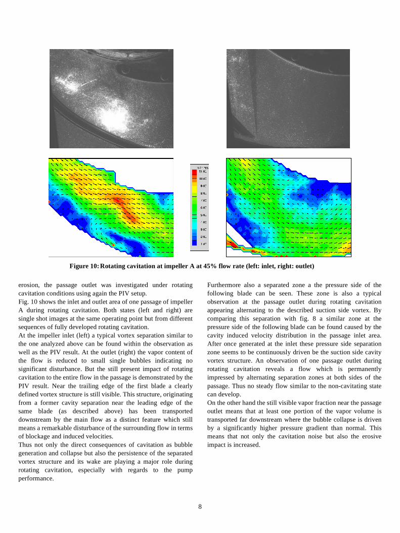
erosion, the passage outlet was investigated under rotatingcavitation conditions using again the PIV setup.Fig. 10 shows the inlet and outlet area of one passage of impellerA during rotating cavitation. Both states (left and right) aresingle shot images at the same operating point but from differentsequences of fully developed rotating cavitation.At the impeller inlet (left) a typical vortex separation similar tothe one analyzed above can be found within the observation aswell as the PIV result. At the outlet (right) the vapor content ofthe flow is reduced to small single bubbles indicating nosignificant disturbance. But the still present impact of rotatingcavitation to the entire flow in the passage is demonstrated by thePIV result. Near the trailing edge of the first blade a clearlydefined vortex structure is still visible. This structure, originatingfrom a former cavity separation near the leading edge of thesame blade (as described above) has been transporteddownstream by the main flow as a distinct feature which stillmeans a remarkable disturbance of the surrounding flow in termsof blockage and induced velocities.Thus not only the direct consequences of cavitation as bubblegeneration and collapse but also the persistence of the separatedvortex structure and its wake are playing a major role duringrotating cavitation, especially with regards to the pumpperformance.
Furthermore also a separated zone a the pressure side of thefollowing blade can be seen. These zone is also a typicalobservation at the passage outlet during rotating cavitationappearing alternating to the described suction side vortex. Bycomparing this separation with fig. 8 a similar zone at thepressure side of the following blade can be found caused by thecavity induced velocity distribution in the passage inlet area.After once generated at the inlet these pressure side separationzone seems to be continuously driven be the suction side cavityvortex structure. An observation of one passage outlet duringrotating cavitation reveals a flow which is permanentlyimpressed by alternating separation zones at both sides of thepassage. Thus no steady flow similar to the non-cavitating statecan develop.On the other hand the still visible vapor fraction near the passageoutlet means that at least one portion of the vapor volume istransported far downstream where the bubble collapse is drivenby a significantly higher pressure gradient than normal. Thismeans that not only the cavitation noise but also the erosiveimpact is increased.
Figure 10: Rotating cavitation at impeller A at 45% flow rate (left: inlet, right: outlet)

9
CONCLUSIONS
The presented paper describes detailed experimental resultsobtained during rotating cavitation. Based on precedingobservations of the phenomenon in a centrifugal impeller of lowspecific speed the experiments were extended to modifiedimpeller geometries as well as detailed flow field investigations.
Using the new impeller geometries a significant change in theonset of rotating cavitation was observed in terms of a shift in σ/2α for different blade numbers while each impeller itself wasshowing a constant σ/2α for all flow rates. In addition thephenomenon of rotating cavitation itself obtained a very similarcharacter for all impellers. By considering the modified passageinlet geometric was shown that the instability limit is defined bya critical cavitation number in relation to the passage throat area.The described shift in σ/2α is therefore reflecting the changedcavity size (σ) required to generate the same instability.
By using an adapted PIV system a detailed unsteady flow fieldinvestigation of the rotating cavitation cycle was performed. Theobtained results confirmed the interaction between the cavity ofone blade and the leading edge (throat area) of the followingblade as the driving reason for rotating cavitation. Within thesemechanism it is not only the pure blockage effect caused by thecavity which influences the flow but mainly the induced velocityfield of the cavity including their wake. Especially the incidenceangle of the following blade which can be considered to be thelink between the unsteady behavior of one cavity and theincreasing or decreasing cavity of the following blade is highlydriven by the velocity and direction of the flow above the cavity.
During separation of the cavity as a typical vortex sheddingmechanism it was shown that a distinct vortex structure isformed and subsequently carried down the passage by the mainflow. These vortex structure and thus the related wake werefound to be very stable on their way downstream even if theentire bubble/vapor content has already collapsed. Therefore asevere disturbance of the passage outlet flow described byalternating separation zones on both sides of the passage wasrecognized as the reason for the pump head drop during rotatingcavitation.
ACKNOWLEDGMENTS
The presented study was carried out in cooperation with DFG(Deutsche Forschungsgemeinschaft).
REFERENCES
[1] Dreiß, A., 1997, „Untersuchung der Laufradkavitation einerradialen Kreiselpumpe durch instationäre Druckmessung imrotierenden System“, Mitteilungen des Pfleiderer.-Instituts 5,Verlag und Bildarchiv W.H. Faragallah.
[2] Friedrichs, J., Kosyna, G., Hofmann, M., Stoffel, B., 2001,„Similarities and Geometrical Effects on Rotating Cavitationin Two Scaled Centrifugal Pumps“, Proceedings of CAV2001, Pasadena.
[3] Friedrichs, J., Kosyna, G., 2002, „Rotating Cavitation in aCentrifugal Pump Impeller of Low Specific Speed“, ASMEJournal of Fluids Engineering, Vol. 124, pp. 356-362.
[4] Friedrichs, J., 2003, „Auswirkungen instationärer Kavita-tionsformen auf Förderhöhenabfall und Kennlinieninstabil-ität von Kreiselpumpen“, Mitteilungen des Pfleiderer.-Insti-tuts 9, Verlag und Bildarchiv W.H. Faragallah.
[5] Hofmann, M., 2001, „Ein Beitrag zur Reduzierung der ero-siven Aggressivität kavitierender Strömungen“, Disserta-tion TU Darmstadt.
[6] Horiguchi, H., Watanabe, S., Tsujimoto, Y., Aoki, M., 2000,„A Theoretical Analysis of Alternate Blade Cavitation inInducers”, ASME Journal of Fluids Engineering, Vol. 122,pp. 156-163.
[7] Host-Madsen, A., McCluskey, D.R., 1994, „On the Accuracyans Reliability of PIV Measurements“, Proc. of the 7th Int.Symp. on Appl. of Laser Techniques to Flow Measurements,Lisbon.
[8] Iga, Y., Nohmi, M., Goto, A., Shin, B.R., Ikohagi, T., 2002,„Numerical Analysis of Unstable Phenomena of Cavitationin Cascade with Finite Blade Numbers“, 9th Int. Symp. onTransport Phenomena and Dynamics of Rotating Machinery,Honolulu, Hawaii.
[9] Traupel, W., 1962, „Die Theorie der Strömung durch Radial-maschinen“, Verlag G. Braun, Karlsruhe.
[10] Tsujimoto, Y., Yoshida, Y., Maekawa, Y., Watanabe, S.,Hashimoto, T., 1997, „Observations of Oscillating Cavita-tion of an Inducer”, ASME Journal of Fluids Engineering,Vol. 119, pp. 775-781.
[11] Tsujimoto, Y., Kamijo, K., Yoshida, Y., 1993, „A Theoreti-cal Analysis of Rotating Cavitation in Inducers”, ASMEJournal of Fluids Engineering, Vol. 115, pp. 135-141.
[12] Tsujimoto, Y., 2001, „Simple rules for Cavitation Instabili-ties in Turbomachinery“, Invited lecture, Cavitation sympo-sium, Cav2001, Pasadena
[13] Watanabe, S., Sato, K., Tsujimoto, Y., Kamijo, K., 1999,„Analysis of Rotating Cavitation in a Finite Pitch CascadeUsing a Closed Cavity Model and a Singularity Method”,ASME Journal of Fluids Engineering, Vol. 121, pp. 834-840.