Embed Size (px)
Citation preview

Unpacking and Setup Guide
EMC®
40U-D Cabinet
Unpacking and Setup Guide300-012-533REV 03
August 29, 2014
This Unpacking and Setup Guide contains information about the EMC 40U-D cabinet.Topics include:
Note
This document was accurate at publication time. Go to EMC Online Support (https://support.emc.com) to ensure that you are using the latest version of this document.
l Before you start .........................................................................................................2l Tools required............................................................................................................2l Hardware acclimation................................................................................................ 3l Steps to unpack and setup cabinet............................................................................ 3l Remove the ramp and shipping material from the cabinet.......................................... 4l Remove the cabinet shipping brackets.......................................................................5l Attach the unloading ramp.........................................................................................6l Roll the cabinet down the ramp..................................................................................7l Position and level the cabinet.................................................................................... 9l Remove internal shipping material.............................................................................9l Attach AC power input cords...................................................................................... 9l Attach (optional) brackets........................................................................................19l Install the lower rack bezel.......................................................................................20l Ground the cabinet.................................................................................................. 21l Repackaging shipping material (2-piece ramp kits only)...........................................21l If you need help....................................................................................................... 24

Before you startThis section contains important information you should read prior to unpacking andsetting up the cabinet.
CAUTION
Some EMC® products are designed for installation by trained service personnel only.Attempts by unqualified personnel to set up and start certain products may result insystem damage and may void product warranties. Contact your EMC representative fordetailed warranty, installation, and initialization policies.
Please dispose of shipping material responsibly, and recycle wherever and wheneverpossible. Cabinet packaging that includes a collapsible downloading ramp can be re-packaged and returned, as described in GUID-B229557A-8F20-46E7-8792-2445F4E02468.
CL5427
Note
The illustrations in this guide are examples only. Depending on what you ordered, yourconfiguration may look somewhat different from what is shown here.
Tools requiredl 9/16-in. (14-mm) socket wrench
l Adjustable wrench
l Scissors, or similar cutting tool
Unpacking and Setup Guide
2 40U-D Cabinet Unpacking and Setup Guide

Hardware acclimationSystems and components must acclimate to the operating environment before power isapplied to them. Once unpackaged, the system must reside in the operating environmentfor up to 16 hours to thermally stabilize and prevent condensation.
If the last 24 hours of theTRANSIT/STORAGE environment was this:
…and the OPERATINGenvironment is this:
…then let the system or componentacclimate in the new environmentthis many hours:
Temperature Relative Humidity
Nominal68-72°F (20-22°C)
Nominal40-55% RH
Nominal68-72°F (20-22°C) 40-55% RH
0-1 hour
Cold <68°F (20°C) Dry <30% RH <86°F (30°C) 4 hours
Damp >30% RH
Hot >72°F (22°C) Dry <30% RH
Humid 30-45% RH
Hot >72°F (22°C) Humid 45-60% RH <86°F (30°C) 8 hours
Hot >72°F (22°C) Humid >60% RH <86°F (30°C) 16 hours
Unknown
IMPORTANT:
l If there are signs of condensation after the recommended acclimation time haspassed, allow an additional eight (8) hours to stabilize.
l Systems and components must not experience changes in temperature and humiditythat are likely to cause condensation to form on or in that system or component. Donot exceed the shipping and storage temperature gradient of 45°F/hr (25°C/hr).
l To facilitate environmental stabilization, open both front and rear cabinet doors.
Steps to unpack and setup cabinetThe steps to unpack, setup and repackage the shipping material are listed in thefollowing table:
Step Task
1 Remove the ramp and shipping material from the cabinet on page 4
2 Remove the cabinet shipping brackets on page 5
3 Attach the unloading ramp on page 6
4 Roll the cabinet down the ramp on page 7
5 Position and level the cabinet on page 9
6 Remove internal shipping material on page 9
7 Attach AC power input cords on page 9
8 Attach (optional) brackets on page 19
Unpacking and Setup Guide
Hardware acclimation 3

Step Task
9 Install the lower rack bezel on page 20
10 Ground the cabinet on page 21
11 GUID-B229557A-8F20-46E7-8792-2445F4E02468
Remove the ramp and shipping material from the cabinetProcedure
1. Remove any boxes and other material from the cabinet sides.
CL4691
2. Do not pull a ramp down from the top. To release the ramp from the pallet, grasp theramp, pull it straight back toward you, then pull it straight up to free it from thescrews.
Unpacking and Setup Guide
4 40U-D Cabinet Unpacking and Setup Guide

Acce
sso
ry K
it
EMC3552
Rotated 90
Bracket
Bracket
Screws
Rear
3. Remove the plastic covering from the cabinet.
Remove the cabinet shipping bracketsProcedure
1. At the rear of the cabinet, remove the rear shipping bracket, by removing the boltsthat go through the bracket to the rack and into the pallet.
2. At the front of the cabinet, remove the bottom rack bezel, if necessary. Pull the bezelstraight out to remove it.
3. Remove the bolts that attach the rack to the front shipping bracket. Your can leave thefront bracket attached to the shipping pallet.
Note
Save the bolts. You may need them later to install optional stabilizer brackets.
Unpacking and Setup Guide
Remove the cabinet shipping brackets 5

CL4831
9/16-in. (14-mm)
Attach the unloading rampProcedure
1. Insert the ramp brackets into the pallet notches in the rear of the pallet.
EMC2843
Rear
2. If your shipment includes a two-piece ramp, attach part A to the pallet and part B topart A.
Unpacking and Setup Guide
6 40U-D Cabinet Unpacking and Setup Guide

CL4692
Roll the cabinet down the rampNOTICE
Make certain the leveling feet are secured in the UP position before moving the cabinet.Secured feet allow the cabinet to roll off the ramp and into position. If you need to adjustthe leveling feet, use an adjustable wrench and turn the feet clockwise to raise them tothe UP position.
EMC2845
LevelingFeet
Rear
Rails
Unpacking and Setup Guide
Roll the cabinet down the ramp 7

WARNING
The cabinet is heavy. Make certain you have sufficient help and secure footing beforerolling the cabinet onto the ramp.
ATTENTION! L'armoire est lourde. Assurez-vous d'obtenir l'aide d'une personne et d'avoirun point d'appui sûr avant d'installer l'armoire sur la rampe.
ACHTUNG! Das Gestell ist schwer. Versichern Sie sich, dass Sie genügend Hilfe habenund dass das Fundament gesichert ist, bevor Sie das Gestell auf die Rampe rollen.
ATTENZIONE! Poiché il cabinet è molto pesante assicurarsi di essere in un numerosufficiente di persone e di avere un appoggio sicuro prima di spingerlo sullo scivolo.
ADVERTENCIA! El bastidor es pesado. Asegúrese de contar con ayuda suficiente y detener un apoyo seguro antes de colocar el bastidor en la rampa.
WARNING
Balance the cabinet from the sides; do not grasp the plastic bezels or other componentson the front of the cabinet.
DO NOT STAND IN FRONT OF THE CABINET
EMC2846
Unpacking and Setup Guide
8 40U-D Cabinet Unpacking and Setup Guide
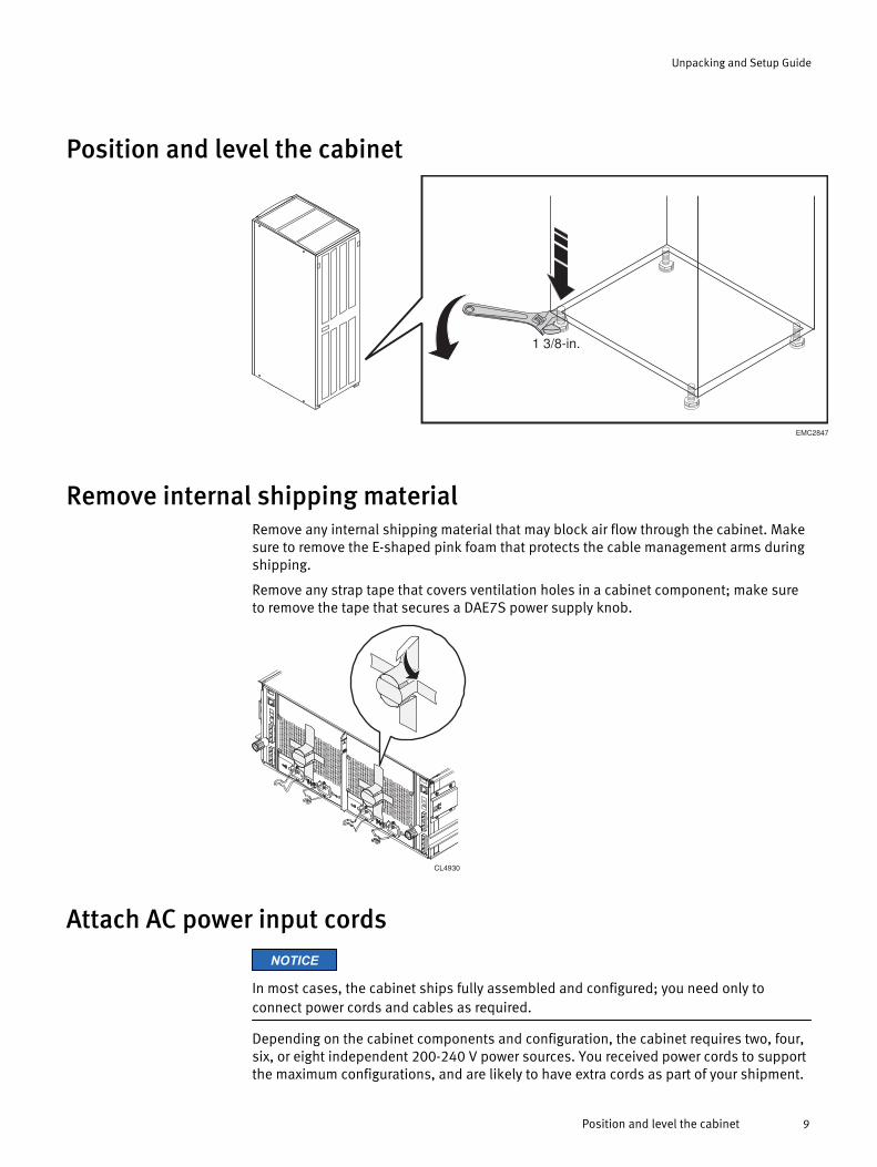
Position and level the cabinet
EMC2847
1 3/8-in.
Remove internal shipping materialRemove any internal shipping material that may block air flow through the cabinet. Makesure to remove the E-shaped pink foam that protects the cable management arms duringshipping.
Remove any strap tape that covers ventilation holes in a cabinet component; make sureto remove the tape that secures a DAE7S power supply knob.
CL4930
Attach AC power input cordsNOTICE
In most cases, the cabinet ships fully assembled and configured; you need only toconnect power cords and cables as required.
Depending on the cabinet components and configuration, the cabinet requires two, four,six, or eight independent 200-240 V power sources. You received power cords to supportthe maximum configurations, and are likely to have extra cords as part of your shipment.
Unpacking and Setup Guide
Position and level the cabinet 9
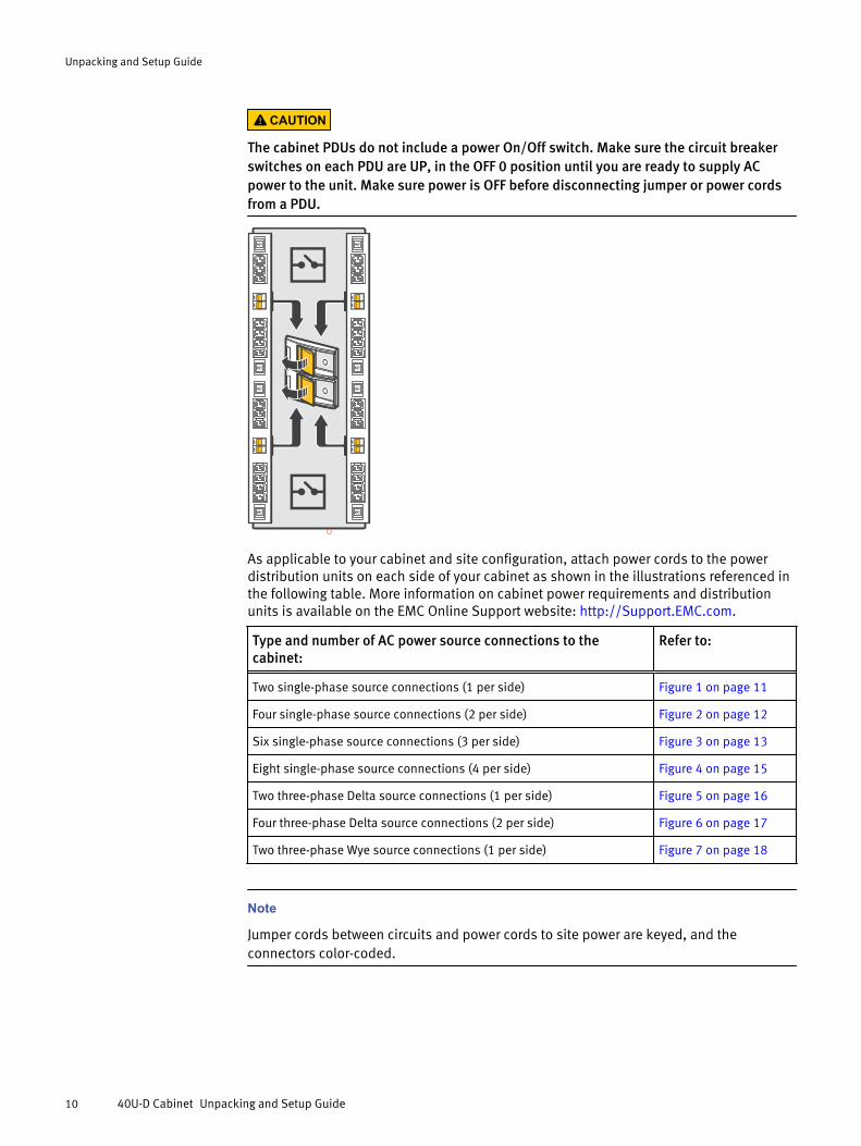
CAUTION
The cabinet PDUs do not include a power On/Off switch. Make sure the circuit breakerswitches on each PDU are UP, in the OFF 0 position until you are ready to supply ACpower to the unit. Make sure power is OFF before disconnecting jumper or power cordsfrom a PDU.
As applicable to your cabinet and site configuration, attach power cords to the powerdistribution units on each side of your cabinet as shown in the illustrations referenced inthe following table. More information on cabinet power requirements and distributionunits is available on the EMC Online Support website: http://Support.EMC.com.
Type and number of AC power source connections to thecabinet:
Refer to:
Two single-phase source connections (1 per side) Figure 1 on page 11
Four single-phase source connections (2 per side) Figure 2 on page 12
Six single-phase source connections (3 per side) Figure 3 on page 13
Eight single-phase source connections (4 per side) Figure 4 on page 15
Two three-phase Delta source connections (1 per side) Figure 5 on page 16
Four three-phase Delta source connections (2 per side) Figure 6 on page 17
Two three-phase Wye source connections (1 per side) Figure 7 on page 18
Note
Jumper cords between circuits and power cords to site power are keyed, and theconnectors color-coded.
Unpacking and Setup Guide
10 40U-D Cabinet Unpacking and Setup Guide

Figure 1 Cabinet supporting two single-phase source connections (1 per side)
A
A
A
A
A
A
A
A
A
A
A
A
A
A
A
A
A
A
A
A
A
A
A
A
A
A
A
A
A
A
A
A
CL4875
A
A
A
A
A
A
A
A
A
A
A
A
A
A
A
A
Unpacking and Setup Guide
Attach AC power input cords 11

Figure 2 Cabinet supporting four single-phase source connections (2 per side)
A
A
A
A
A
A
A
A
A
A
A
A
A
A
A
A
A
A
A
A
A
A
A
A
A
A
A
A
A
A
A
A
CL4876
A
A
A
A
A
A
A
A
A
A
A
A
A
A
A
A
Unpacking and Setup Guide
12 40U-D Cabinet Unpacking and Setup Guide

Figure 3 Cabinet supporting six single-phase source connections (3 per side)
A
A
A
A
A
A
A
A
A
A
A
A
A
A
A
A
A
A
A
A
A
A
A
A
A
A
A
A
A
A
A
A
CL4877
A
A
A
A
A
A
A
A
A
A
A
A
A
A
A
A
OR
Unpacking and Setup Guide
Attach AC power input cords 13

A
A
A
A
A
A
A
A
A
A
A
A
A
A
A
A
A
A
A
A
A
A
A
A
A
A
A
A
A
A
A
A
CL5024
A
A
A
A
A
A
A
A
A
A
A
A
A
A
A
A
Unpacking and Setup Guide
14 40U-D Cabinet Unpacking and Setup Guide

Figure 4 Cabinet supporting eight single-phase source connections (4 per side)
A
A
A
A
A
A
A
A
A
A
A
A
A
A
A
A
A
A
A
A
A
A
A
A
A
A
A
A
A
A
A
A
CL5437
A
A
A
A
A
A
A
A
A
A
A
A
A
A
A
A
Unpacking and Setup Guide
Attach AC power input cords 15
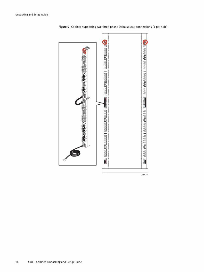
Figure 5 Cabinet supporting two three-phase Delta source connections (1 per side)
CL5438
Unpacking and Setup Guide
16 40U-D Cabinet Unpacking and Setup Guide

Figure 6 Cabinet supporting four three-phase Delta source connections (2 per side)
CL5439
Unpacking and Setup Guide
Attach AC power input cords 17

Figure 7 Cabinet supporting two three-phase Wye source connections (1 per side)
CL5440
Unpacking and Setup Guide
18 40U-D Cabinet Unpacking and Setup Guide

Attach (optional) bracketsWe strongly recommend that you secure your cabinet to the floor with stabilizingbrackets. Make sure the cabinet is in its final location before attaching the brackets, thenuse the supplied bolts and mounting holes to attach them to the cabinet and floor.
Figure 8 Anti-tip bracket (installed on the front of cabinet)
CL4830
(3)
(3)
Figure 9 Anti-move bracket (installed on the front and back of cabinet)
CL4832
(3)
(3)
Unpacking and Setup Guide
Attach (optional) brackets 19

Figure 10 Seismic bracket (installed on the front, back, and sides of the cabinet)
CL4833
(3)
(3)
(3)
(3)
Install the lower rack bezelIn some cases, the lower rack bezel ships unattached from the cabinet, or was removedto detach the shipping brackets. Push the lower rack bezel onto the ball studs at eitherside of the bottom front of the cabinet.
CL4829
(2)
Unpacking and Setup Guide
20 40U-D Cabinet Unpacking and Setup Guide

Ground the cabinetEquipment correctly installed within the cabinet is grounded through the AC power cablesand connectors. In general, supplemental grounding is not required.
If your site requires external grounding (for example, to a common grounding networkbeneath the site floor), you can use the grounding lugs provided on each of the cabinet’sbottom supports.
CL4827
046-003-3
50
Repackaging shipping material (2-piece ramp kits only)
Follow these steps to repackage the cabinet shipping material:
Procedure
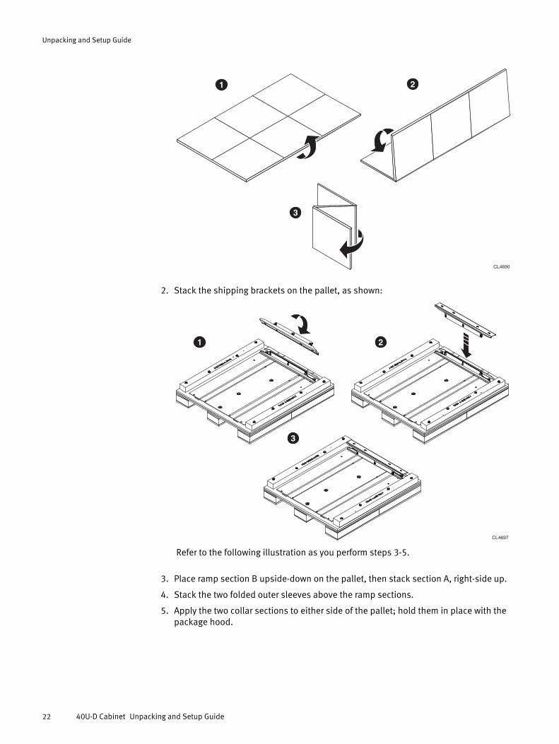
1. Lay each of the outer sleeves flat, then fold it lengthwise before collapsing the threesections, as shown:
Unpacking and Setup Guide
Ground the cabinet 21
3
CL4690
1 2
2. Stack the shipping brackets on the pallet, as shown:
CL4697
3
21
Refer to the following illustration as you perform steps 3-5.
3. Place ramp section B upside-down on the pallet, then stack section A, right-side up.
4. Stack the two folded outer sleeves above the ramp sections.
5. Apply the two collar sections to either side of the pallet; hold them in place with thepackage hood.
Unpacking and Setup Guide
22 40U-D Cabinet Unpacking and Setup Guide

CL4696
6. Band the unit with shipping straps as shown:
CL4751
7. Use the following information to determine how to return the repackaged shippingmaterial:
l If the carrier unpacked the cabinet, the carrier handles the return shipment to theEMC packaging supplier.
l If the cabinet was unpacked after delivery, refer to the contact number attached tothe pamphlet for repacking. This contact is the carrier network for the initialshipment and they will follow the same process as for the initial shipments.
Unpacking and Setup Guide
Repackaging shipping material (2-piece ramp kits only) 23

If you need helpFor questions about technical support and service, contact you service provider.
For questions about upgrades, contact your sales office.
More information about this and other products is available on the EMC Online Supportwebsite at http://Support.EMC.com.
Unpacking and Setup Guide
24 40U-D Cabinet Unpacking and Setup Guide

Copyright © 2011-2014 EMC Corporation. All rights reserved. Published in USA.
Published August 29, 2014
EMC believes the information in this publication is accurate as of its publication date. The information is subject to change withoutnotice.
The information in this publication is provided as is. EMC Corporation makes no representations or warranties of any kind withrespect to the information in this publication, and specifically disclaims implied warranties of merchantability or fitness for aparticular purpose. Use, copying, and distribution of any EMC software described in this publication requires an applicable softwarelicense.
EMC², EMC, and the EMC logo are registered trademarks or trademarks of EMC Corporation in the United States and other countries.All other trademarks used herein are the property of their respective owners.
For the most up-to-date regulatory document for your product line, go to EMC Online Support (https://support.emc.com).
Unpacking and Setup Guide
If you need help 25