Embed Size (px)
Citation preview
1
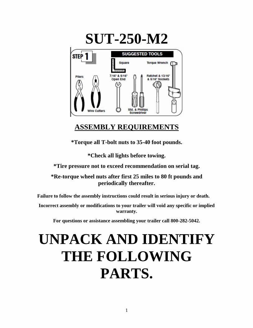
SUT-250-M2
ASSEMBLY REQUIREMENTS
*Torque all T-bolt nuts to 35-40 foot pounds.
*Check all lights before towing.
*Tire pressure not to exceed recommendation on serial tag.
*Re-torque wheel nuts after first 25 miles to 80 ft pounds and periodically thereafter.
Failure to follow the assembly instructions could result in serious injury or death. Incorrect assembly or modifications to your trailer will void any specific or implied
warranty.
For questions or assistance assembling your trailer call 800-282-5042.
UNPACK AND IDENTIFY THE FOLLOWING
PARTS.
2
Tongue sections. Axle and springs.
Cross members & side rails. Front upright & cross bar assembly.
Rear upright & cross bar assembly. Tongue to cross member angles.
3
Wheels, fenders, & hardware. Skid.
Tail light brackets.
4
Frame assembly
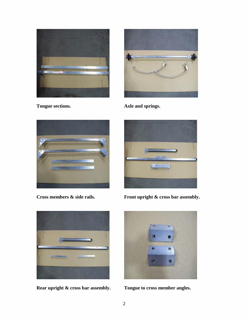
Lay the rear cross member on the floor. The two bolts mounted in the center will be facing the rear of the trailer.
Locate the side rail with the bolt installed.
With the bolt facing what will be the inside of the trailer, slide the side rail into the corner bracket from the rear.
5
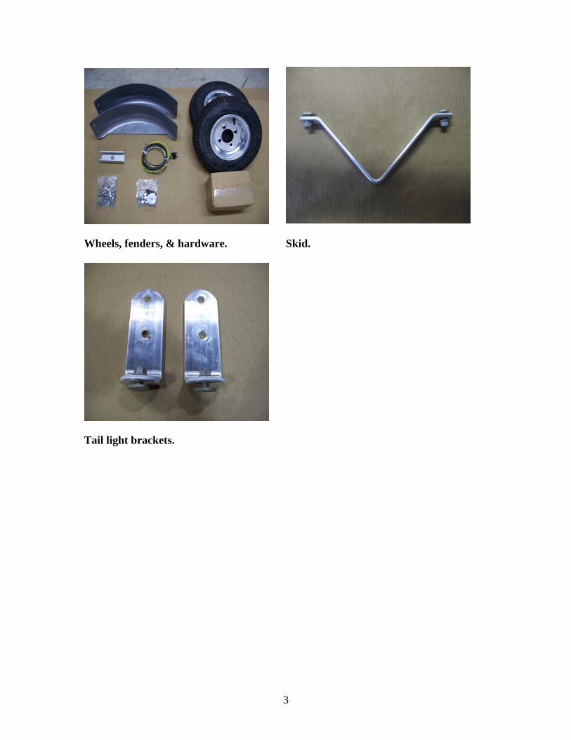
Slide it all the way toward the front of the trailer until it is flush with the back edge of the rear spring hanger. Repeat for the other side. Do not tighten the triangular shaped corner brackets yet.
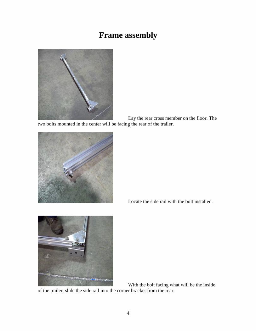
Your frame should look like this.
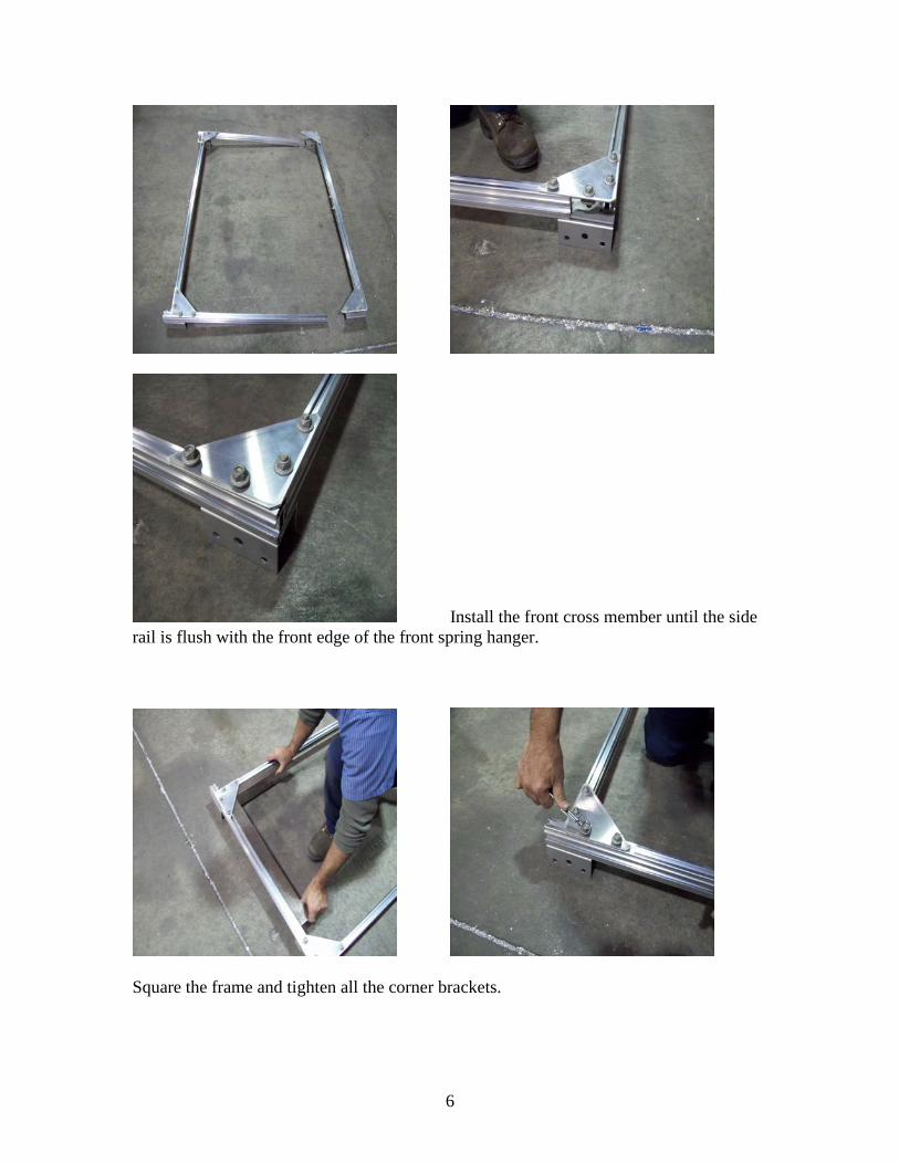
6
Install the front cross member until the side rail is flush with the front edge of the front spring hanger.
Square the frame and tighten all the corner brackets.
7
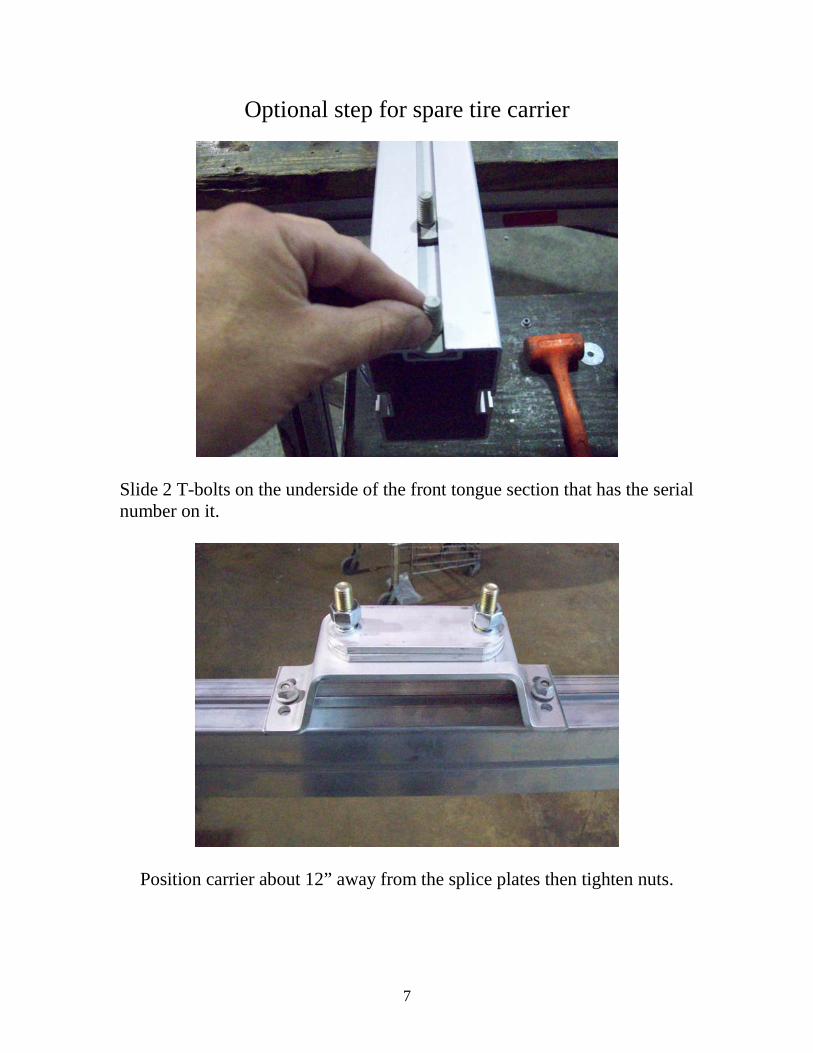
Optional step for spare tire carrier
Slide 2 T-bolts on the underside of the front tongue section that has the serial number on it.
Position carrier about 12” away from the splice plates then tighten nuts.
8
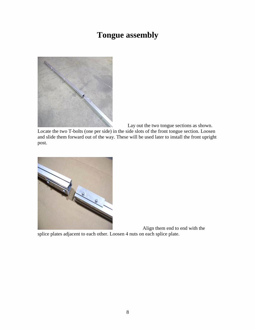
Tongue assembly
Lay out the two tongue sections as shown. Locate the two T-bolts (one per side) in the side slots of the front tongue section. Loosen and slide them forward out of the way. These will be used later to install the front upright post.
Align them end to end with the splice plates adjacent to each other. Loosen 4 nuts on each splice plate.
9
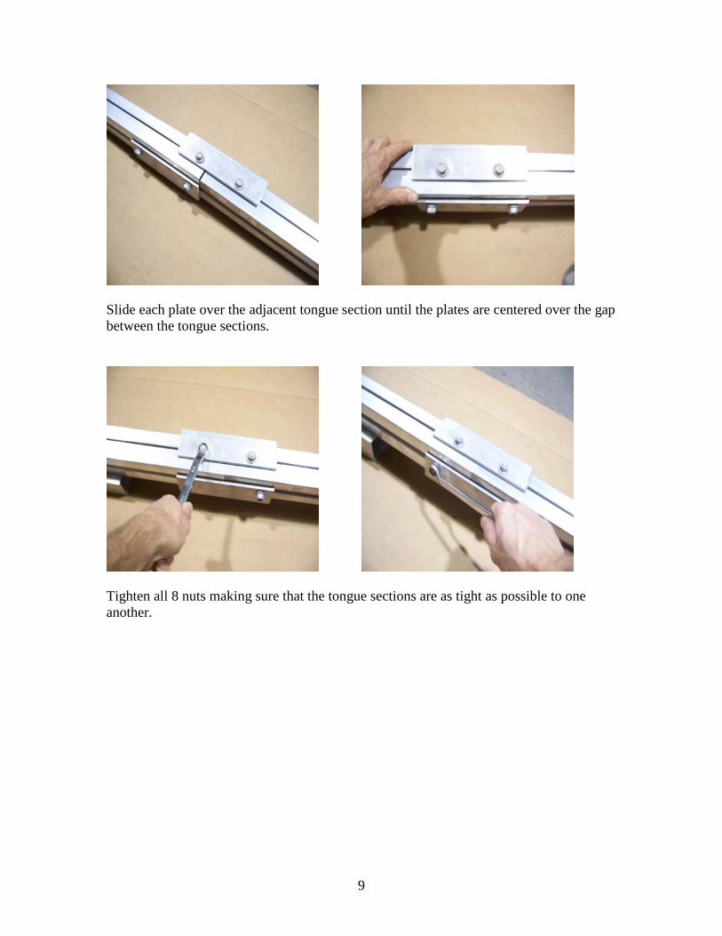
Slide each plate over the adjacent tongue section until the plates are centered over the gap between the tongue sections.
Tighten all 8 nuts making sure that the tongue sections are as tight as possible to one another.
10
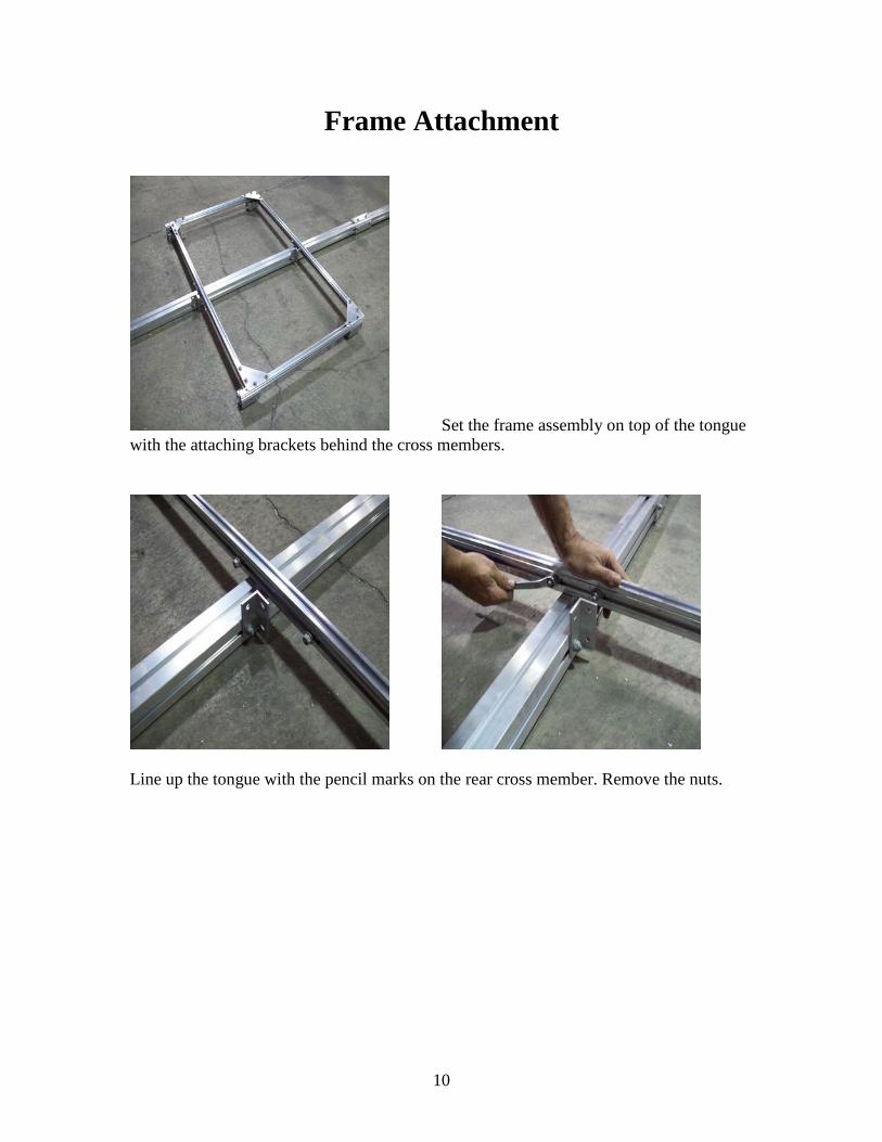
Frame Attachment
Set the frame assembly on top of the tongue with the attaching brackets behind the cross members.
Line up the tongue with the pencil marks on the rear cross member. Remove the nuts.
11
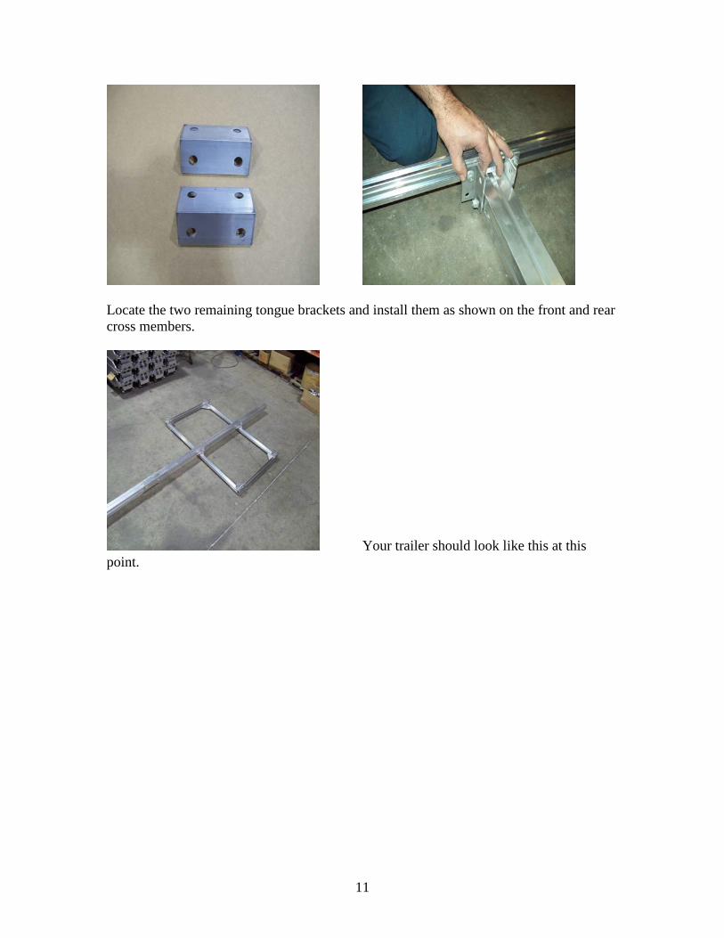
Locate the two remaining tongue brackets and install them as shown on the front and rear cross members.
Your trailer should look like this at this point.
12
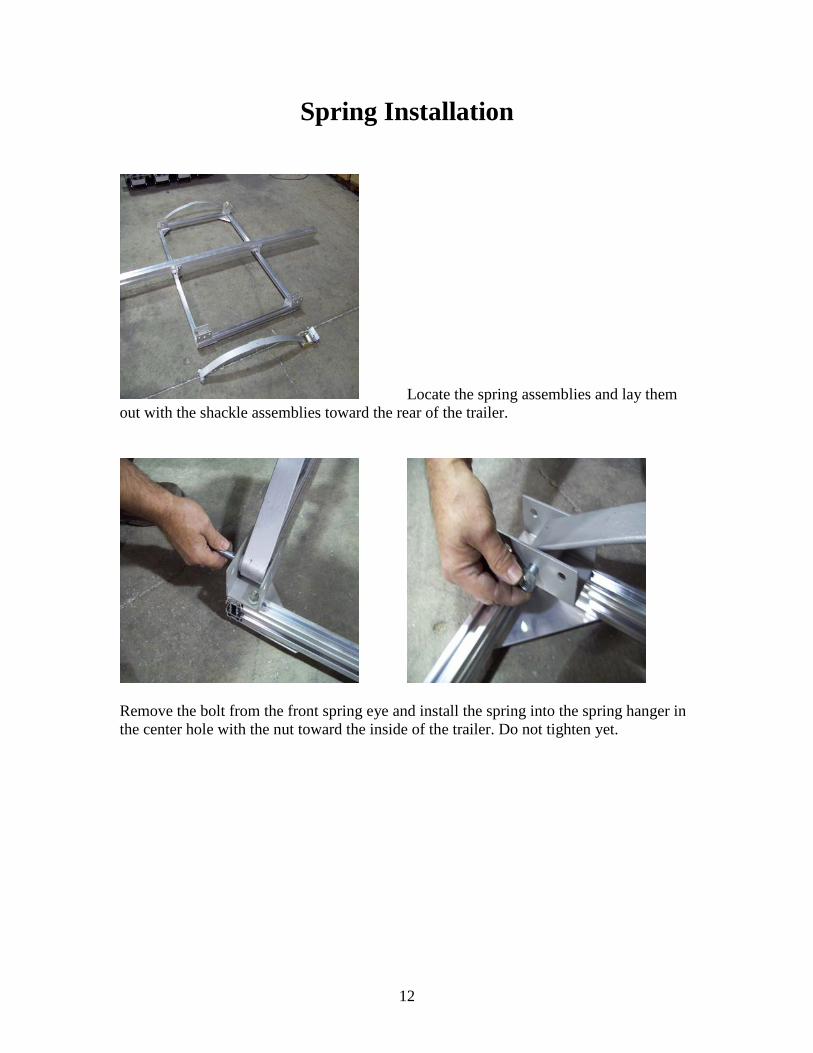
Spring Installation
Locate the spring assemblies and lay them out with the shackle assemblies toward the rear of the trailer.
Remove the bolt from the front spring eye and install the spring into the spring hanger in the center hole with the nut toward the inside of the trailer. Do not tighten yet.
13
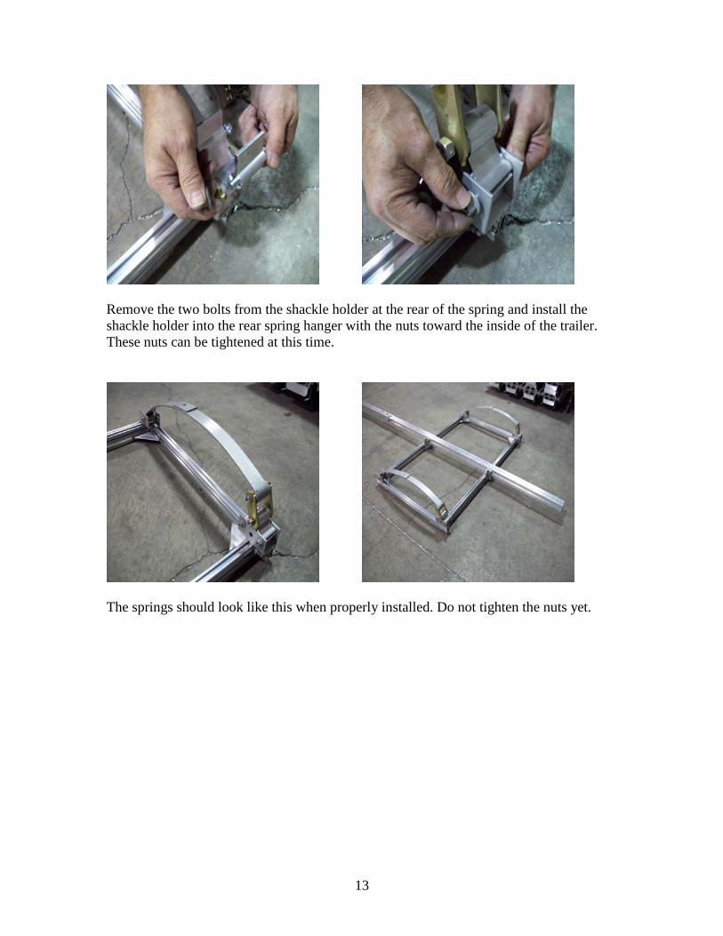
Remove the two bolts from the shackle holder at the rear of the spring and install the shackle holder into the rear spring hanger with the nuts toward the inside of the trailer. These nuts can be tightened at this time.
The springs should look like this when properly installed. Do not tighten the nuts yet.
14
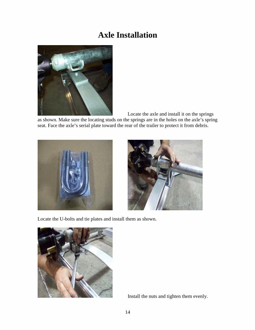
Axle Installation
Locate the axle and install it on the springs as shown. Make sure the locating studs on the springs are in the holes on the axle’s spring seat. Face the axle’s serial plate toward the rear of the trailer to protect it from debris.
Locate the U-bolts and tie plates and install them as shown.
Install the nuts and tighten them evenly.
15
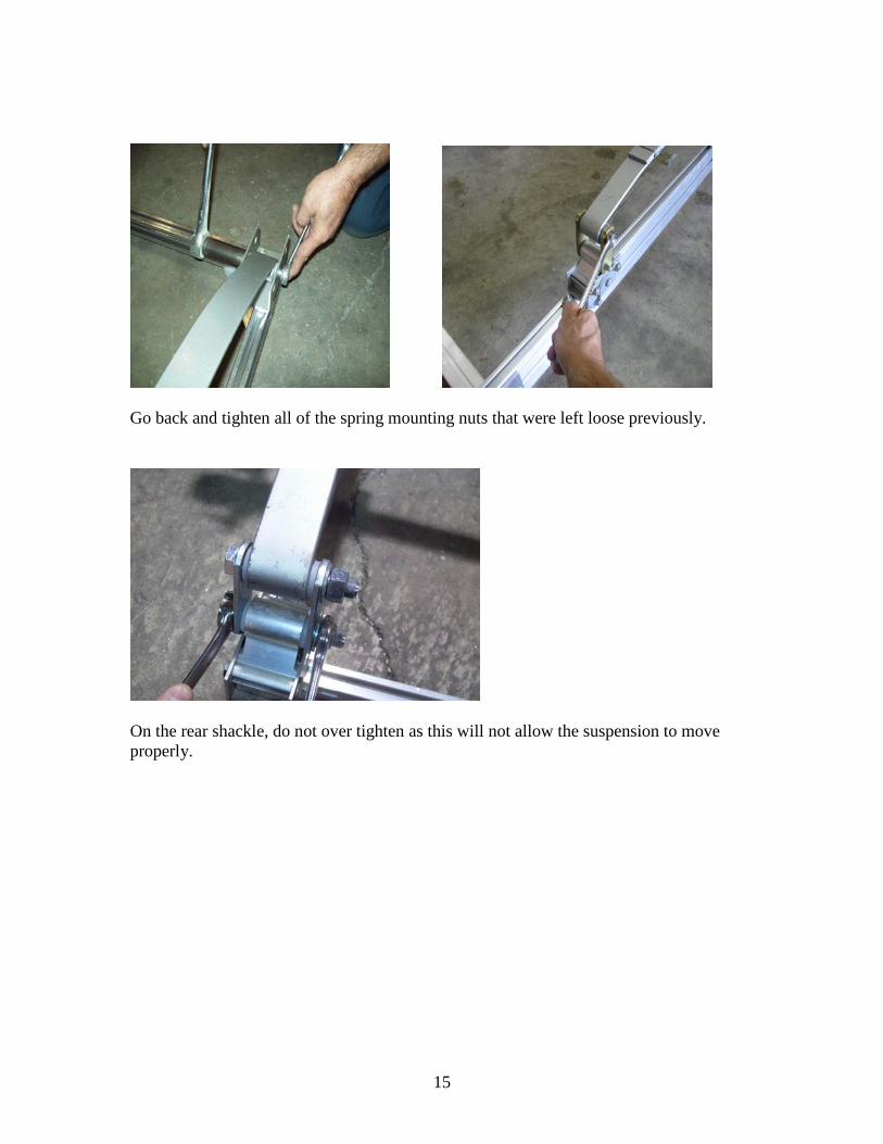
Go back and tighten all of the spring mounting nuts that were left loose previously.
On the rear shackle, do not over tighten as this will not allow the suspension to move properly.
16
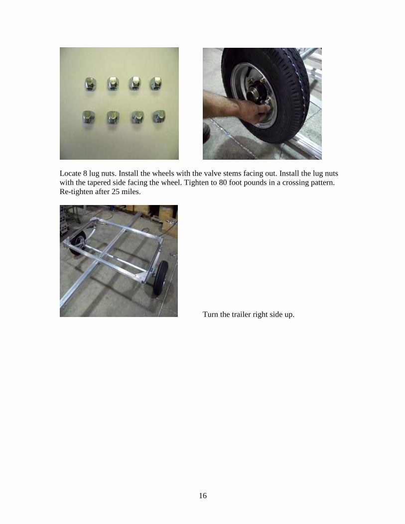
Locate 8 lug nuts. Install the wheels with the valve stems facing out. Install the lug nuts with the tapered side facing the wheel. Tighten to 80 foot pounds in a crossing pattern. Re-tighten after 25 miles.
Turn the trailer right side up.
17
Fender Installation
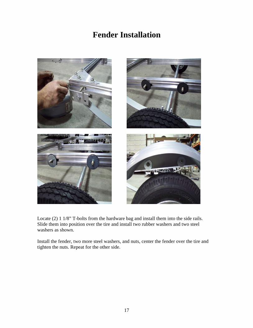
Locate (2) 1 1/8” T-bolts from the hardware bag and install them into the side rails. Slide them into position over the tire and install two rubber washers and two steel washers as shown. Install the fender, two more steel washers, and nuts, center the fender over the tire and tighten the nuts. Repeat for the other side.
18
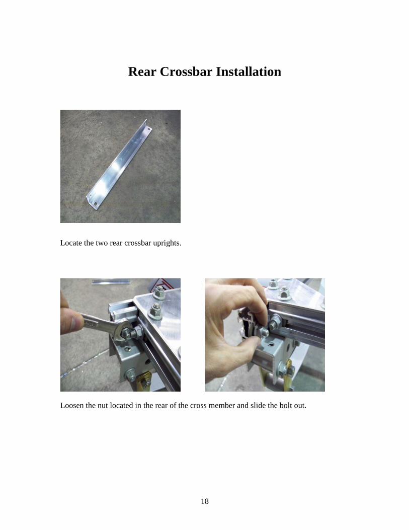
Rear Crossbar Installation
Locate the two rear crossbar uprights.
Loosen the nut located in the rear of the cross member and slide the bolt out.
19
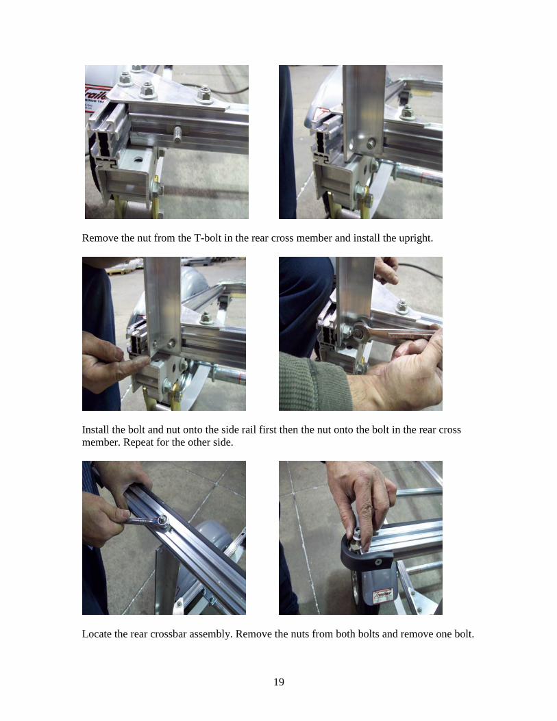
Remove the nut from the T-bolt in the rear cross member and install the upright.
Install the bolt and nut onto the side rail first then the nut onto the bolt in the rear cross member. Repeat for the other side.
Locate the rear crossbar assembly. Remove the nuts from both bolts and remove one bolt.
20
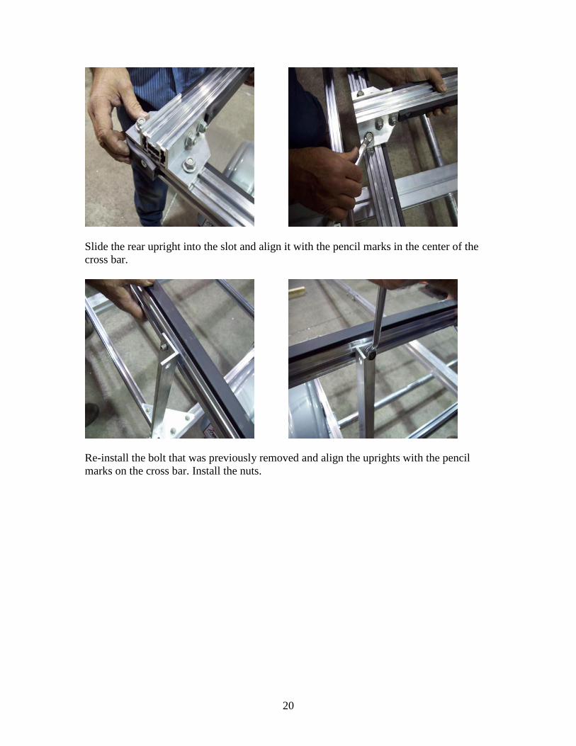
Slide the rear upright into the slot and align it with the pencil marks in the center of the cross bar.
Re-install the bolt that was previously removed and align the uprights with the pencil marks on the cross bar. Install the nuts.
21
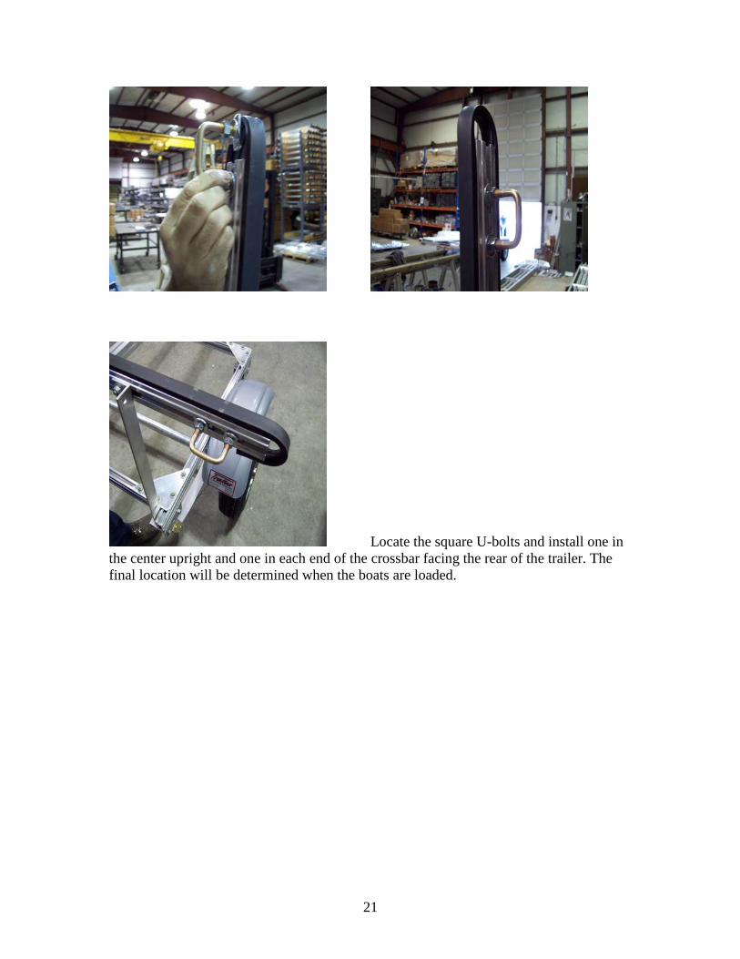
Locate the square U-bolts and install one in the center upright and one in each end of the crossbar facing the rear of the trailer. The final location will be determined when the boats are loaded.
22
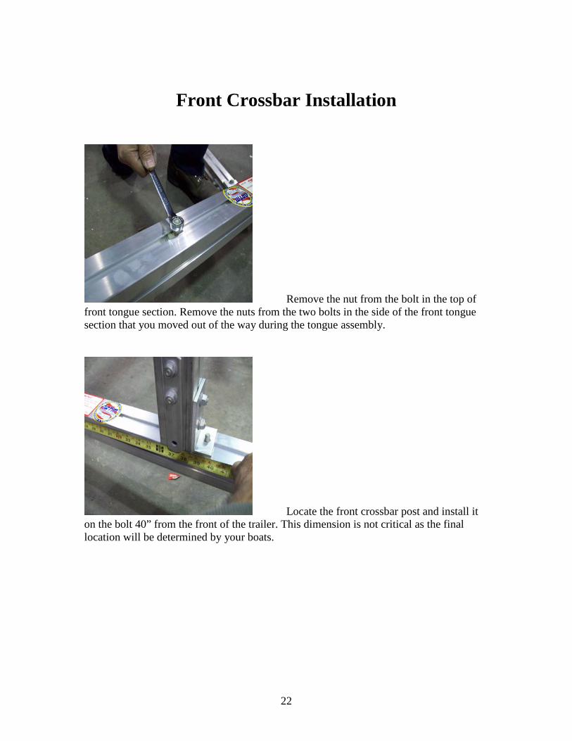
Front Crossbar Installation
Remove the nut from the bolt in the top of front tongue section. Remove the nuts from the two bolts in the side of the front tongue section that you moved out of the way during the tongue assembly.
Locate the front crossbar post and install it on the bolt 40” from the front of the trailer. This dimension is not critical as the final location will be determined by your boats.
23
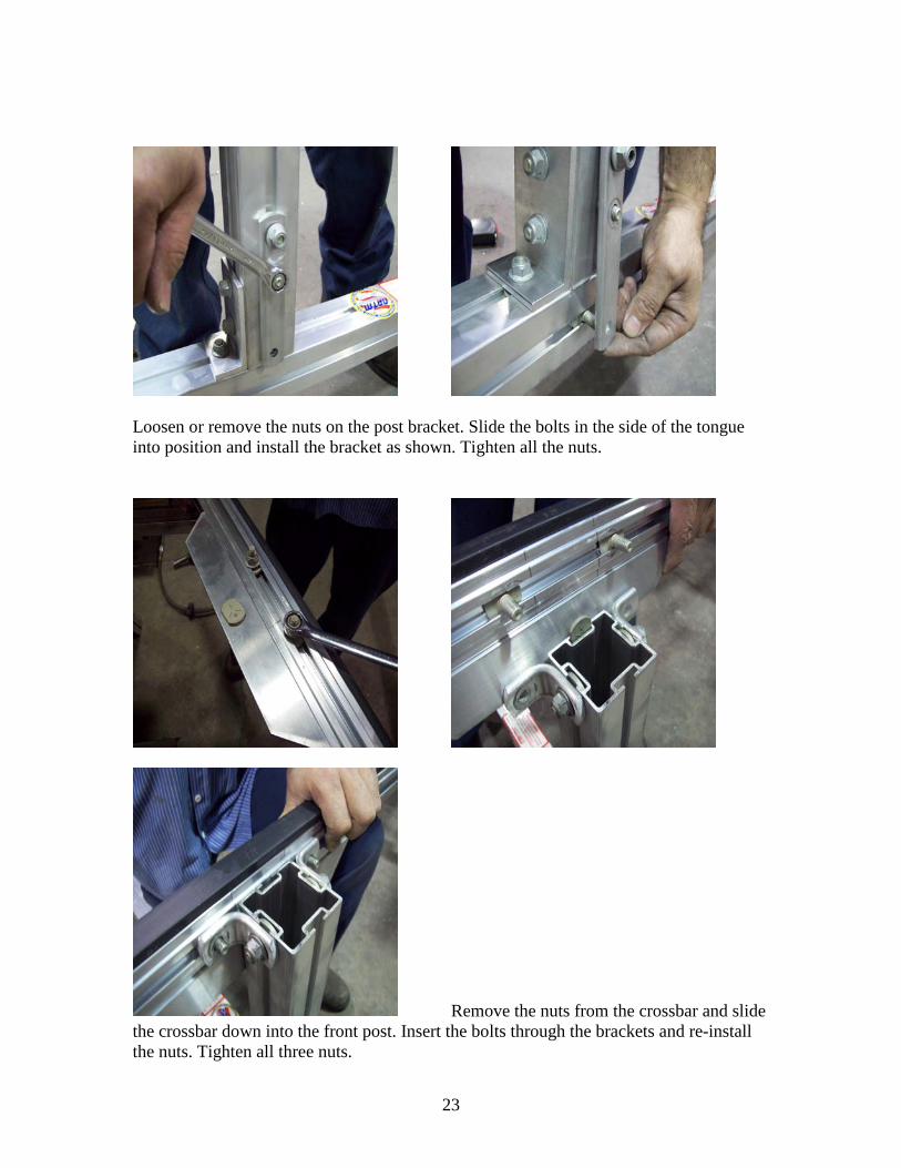
Loosen or remove the nuts on the post bracket. Slide the bolts in the side of the tongue into position and install the bracket as shown. Tighten all the nuts.
Remove the nuts from the crossbar and slide the crossbar down into the front post. Insert the bolts through the brackets and re-install the nuts. Tighten all three nuts.
24
Skid, Running light bracket, running lights.
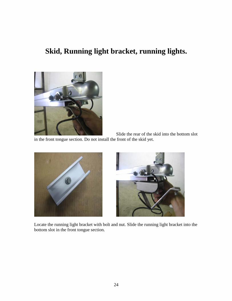
Slide the rear of the skid into the bottom slot in the front tongue section. Do not install the front of the skid yet.
Locate the running light bracket with bolt and nut. Slide the running light bracket into the bottom slot in the front tongue section.
25
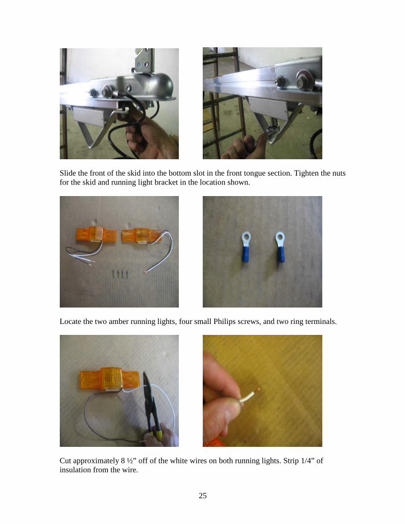
Slide the front of the skid into the bottom slot in the front tongue section. Tighten the nuts for the skid and running light bracket in the location shown.
Locate the two amber running lights, four small Philips screws, and two ring terminals.
Cut approximately 8 ½” off of the white wires on both running lights. Strip 1/4” of insulation from the wire.
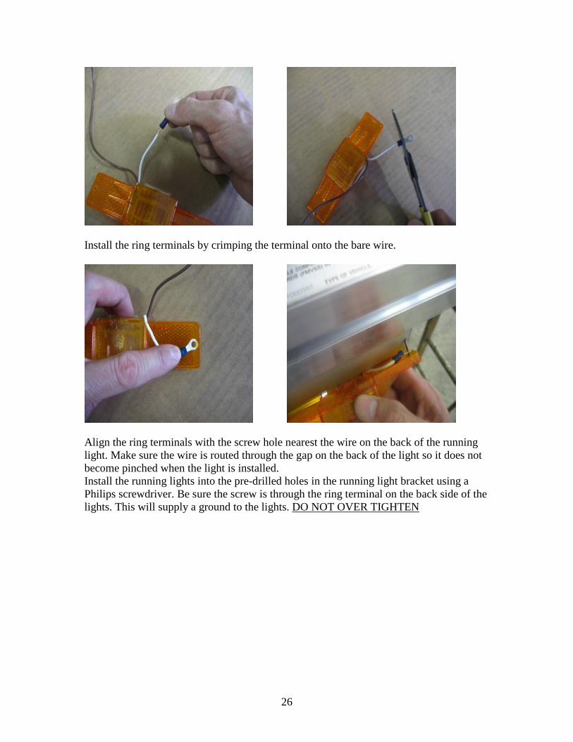
26
Install the ring terminals by crimping the terminal onto the bare wire.
Align the ring terminals with the screw hole nearest the wire on the back of the running light. Make sure the wire is routed through the gap on the back of the light so it does not become pinched when the light is installed. Install the running lights into the pre-drilled holes in the running light bracket using a Philips screwdriver. Be sure the screw is through the ring terminal on the back side of the lights. This will supply a ground to the lights. DO NOT OVER TIGHTEN
27
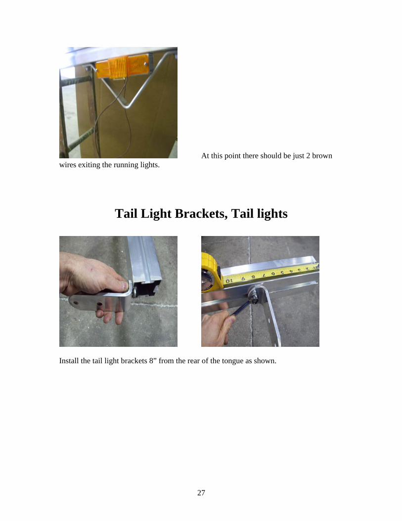
At this point there should be just 2 brown wires exiting the running lights.
Tail Light Brackets, Tail lights
Install the tail light brackets 8” from the rear of the tongue as shown.
28
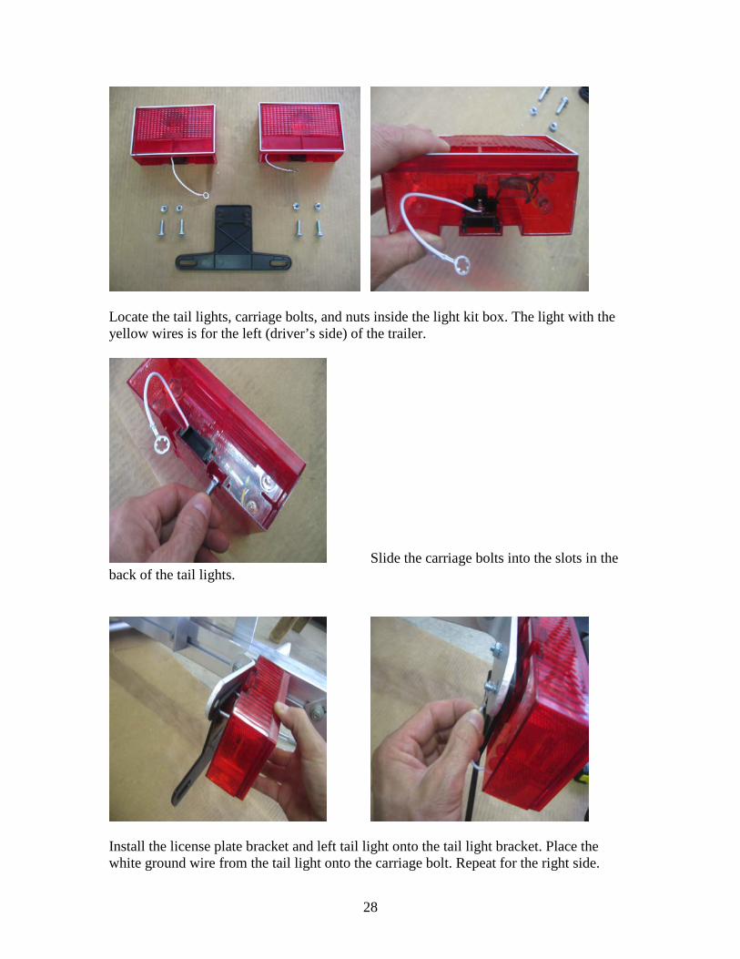
Locate the tail lights, carriage bolts, and nuts inside the light kit box. The light with the yellow wires is for the left (driver’s side) of the trailer.
Slide the carriage bolts into the slots in the back of the tail lights.
Install the license plate bracket and left tail light onto the tail light bracket. Place the white ground wire from the tail light onto the carriage bolt. Repeat for the right side.
29
Wiring
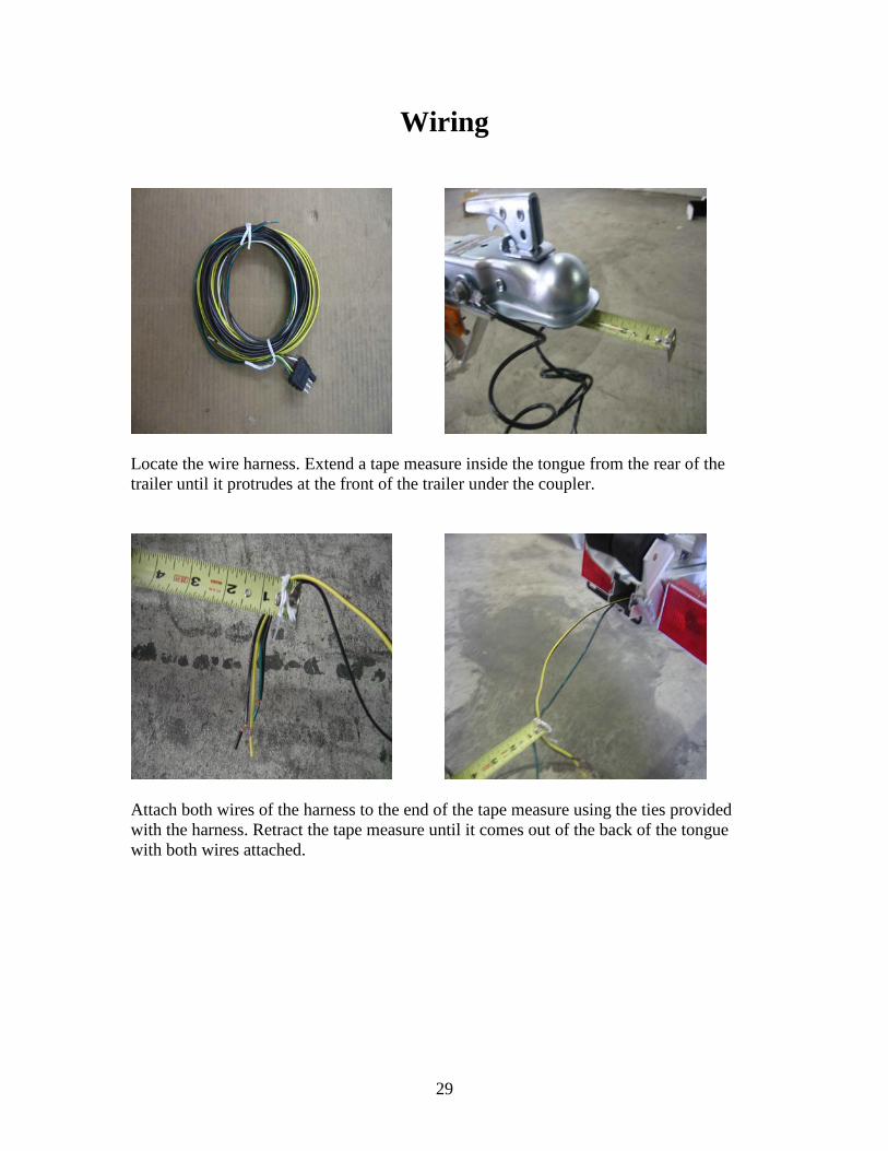
Locate the wire harness. Extend a tape measure inside the tongue from the rear of the trailer until it protrudes at the front of the trailer under the coupler.
Attach both wires of the harness to the end of the tape measure using the ties provided with the harness. Retract the tape measure until it comes out of the back of the tongue with both wires attached.
30
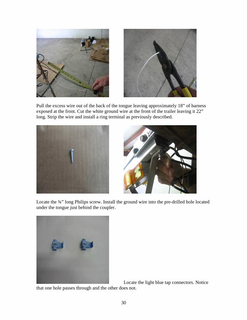
Pull the excess wire out of the back of the tongue leaving approximately 18” of harness exposed at the front. Cut the white ground wire at the front of the trailer leaving it 22” long. Strip the wire and install a ring terminal as previously described.
Locate the ¾” long Philips screw. Install the ground wire into the pre-drilled hole located under the tongue just behind the coupler.
Locate the light blue tap connectors. Notice that one hole passes through and the other does not.
31
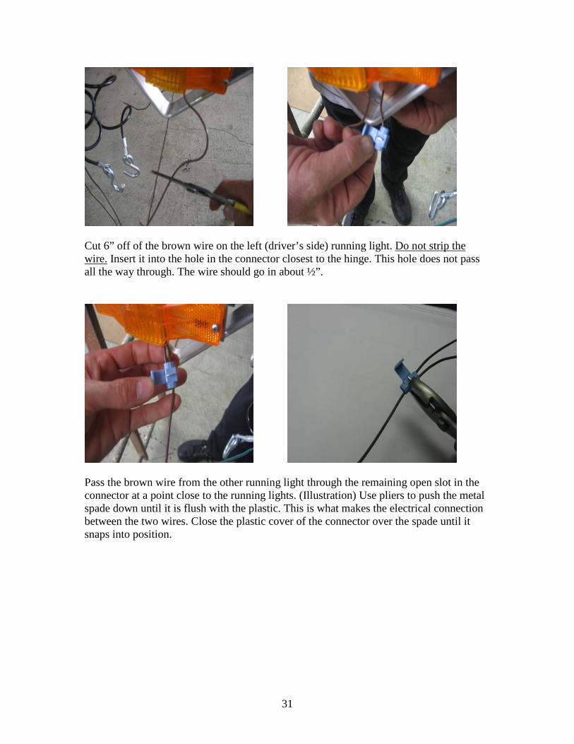
Cut 6” off of the brown wire on the left (driver’s side) running light. Do not strip the wire. Insert it into the hole in the connector closest to the hinge. This hole does not pass all the way through. The wire should go in about ½”.
Pass the brown wire from the other running light through the remaining open slot in the connector at a point close to the running lights. (Illustration) Use pliers to push the metal spade down until it is flush with the plastic. This is what makes the electrical connection between the two wires. Close the plastic cover of the connector over the spade until it snaps into position.
32
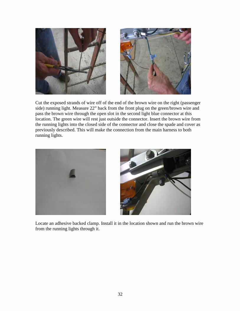
Cut the exposed strands of wire off of the end of the brown wire on the right (passenger side) running light. Measure 22” back from the front plug on the green/brown wire and pass the brown wire through the open slot in the second light blue connector at this location. The green wire will rest just outside the connector. Insert the brown wire from the running lights into the closed side of the connector and close the spade and cover as previously described. This will make the connection from the main harness to both running lights.
Locate an adhesive backed clamp. Install it in the location shown and run the brown wire from the running lights through it.
33
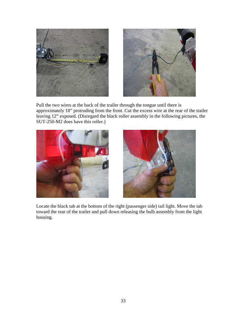
Pull the two wires at the back of the trailer through the tongue until there is approximately 18” protruding from the front. Cut the excess wire at the rear of the trailer leaving 12” exposed. (Disregard the black roller assembly in the following pictures, the SUT-250-M2 does have this roller.)
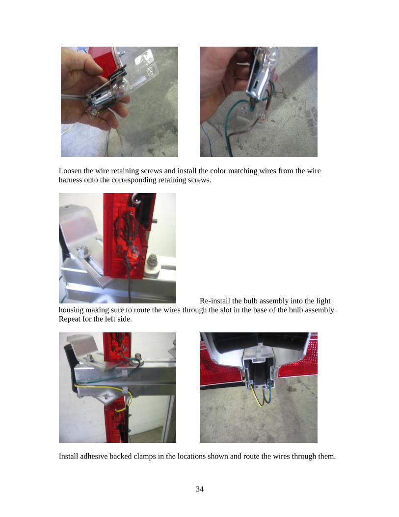
Locate the black tab at the bottom of the right (passenger side) tail light. Move the tab toward the rear of the trailer and pull down releasing the bulb assembly from the light housing.
34
Loosen the wire retaining screws and install the color matching wires from the wire harness onto the corresponding retaining screws.
Re-install the bulb assembly into the light housing making sure to route the wires through the slot in the base of the bulb assembly. Repeat for the left side.
Install adhesive backed clamps in the locations shown and route the wires through them.
35
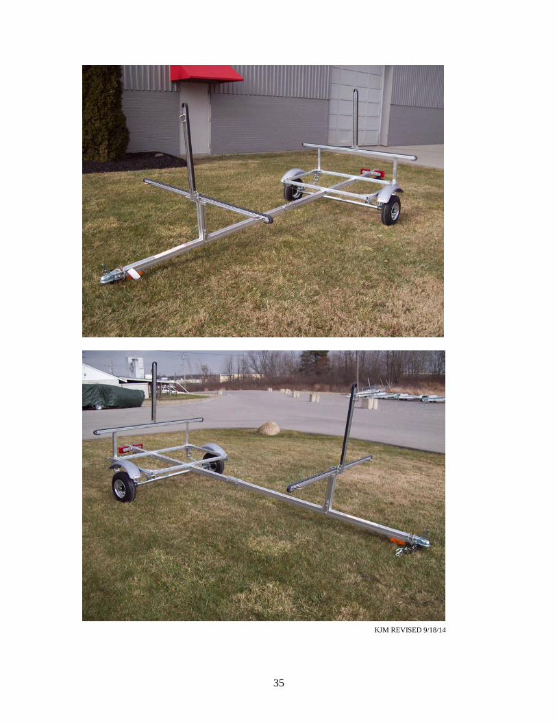
KJM REVISED 9/18/14