Embed Size (px)
DESCRIPTION
Unox XVC/XBC user manual english
Citation preview
Notice d’Utilisation FRANÇAIS
Instruction manual ENGLISH
Manuale d'istruzione ITALIANO
Manual Instrucciones ESPAÑOL
XVC-XBC

English
Explanation of pictograms
2
General pictograms
Danger!Situation presenting immediate danger, or a hazardous situation which could cause injury or death.
Danger: fire hazard!
Danger: high voltage!
Danger: corrosive substances.
Danger: risk of burns.
Caution: non-observance may damage property.
Recommendations for everyday use
Information
English
BakerTop™ChefTop™
Summary of contents
Explanation of pictograms 2
Summary of contents 3
Introduction 4
INSTRUCTIONS FOR THE USER
- Safety regulations 5-8
Appliance operating instructions and Guarantee 9
ChefTouch-BakerTouch digital control panel 10
- Control panel operation 11
Setting the parameters 12-16
Selecting the cooking steps 17
Setting the cooking programs
- Cooking with a set time and oven cavity temperature 18
- Cooking with the core probe at a set oven cavity temperature 19
- Cooking with the core probe at a set Delta T 20
User programming procedures 21
Standard functions
- LASTP function 22
- Automatic washing programs 22
- "COOL" program for oven cavity cooling 23
- ADAPTIVE.Clima function 24
Pre-set cooking procedures 25
MAXI.Link technology 26
Cooking principles 27
Oven-user communication
- Warning messages: 28-29
- Alarm messages: 29-30
- Maintenance in the event of a malfunction: 30
INSTRUCTIONS FOR THE INSTALLER
- Safety regulations 31
Instructions for appliance transportation 32
Appliance installation 33-34
Positioning 35-41
Electrical connections 42-44
Gas connections 45-51
Plumbing connections 52-53
Oven cavity smoke exhaust 54
Connection of accessories 55
Oven stacking 56
Certification 57
3
English
4
Dear Customer, We would like to congratulate and thank you for choosing to purchase an oven in the ChefTop™/ BakerTop™ range; we hope this is just the beginning of a fruitful and long-lasting partnership.As you are aware, the ChefTop™/ BakerTop™ range of ovens and all the complementary accessories designed for it (blast chiller, holding cabinet, special trays and racks) were specifically created to carry out any cooking process, from beginning to end, regardless of its level of complexity.
The innovative Chef Touch digital control panel allows you to control all the UNOX equipment connected to the oven from a single point.
Your ChefTop™ / BakerTop™ oven features exclusive ADAPTIVE.Clima technology, which offers extremely reliable and consistent results, regardless of the number of trays placed inside.In fact, the ChefTop™ / BakerTop™ oven constantly monitors all cooking parameters, not only in terms of temperature, but also the current humidity level inside the cavity. This guarantees the most suitable cooking program is always applied, to help you achieve perfect results every time. ADAPTIVE.Clima technology also means you can repeat a cooking pro-cedure already stored in the memory countless times, in the certainty that the results will always be the same, regardless of whether the oven is operating with all trays inserted or with just one tray placed inside.
AIR.Maxi technology, with the option of setting three different motor revolution speeds and three semi-static operating modes, can be used to adjust the airflow inside the oven cavity to suit your own requirements: from high-speed settings for quick and intense cooking programs, to low-speed settings used for delicate, slow-cooked food, right through to semi-static operation which allows you to control even the most challenging pastry and bread cooking procedures.
MULTI.Time technology can also be used to set up to 9 timers, giving you maximum control, even when cooking several different foods at the same oven cavity temperature and humidity levels for different periods of time.
If your ChefTop™/BakerTop™ oven features two core probes with extra-fine needles (external to the oven), you will also be able to cook vacuum-packed goods perfectly and steam particularly delicate or small foods.
UNOX S.p.A.
Dealer: Installer:
Installation date:
Introduction
English
BakerTop™ChefTop™
5
CautionPlease read this booklet carefully, as it provides important information regarding safe oven operation. Keep it in a safe place so that the various operators may consult it as necessary.
Safety regulationsIncorrect installation, assistance, maintenance or cleaning procedures, or any modifications made to the appliance, may damage property or result in injury or even fatal accidents. Read the operating manual carefully before using the appliance.
General safety regulations
This appliance may only be used by qualified personnel, to cook food in professional and industrial kitchens.Any other application does not conform to the specified use and is therefore considered hazardous.The equipment must be used only for its intended purpose; any other application will be considered improper.
The equipment may be used for the following purposes:- for cooking all Pastry and Bread products, whether fresh or frozen;- for cooking all Gastronomic products, whether fresh or frozen;- for bringing chilled and frozen food back to normal temperatures;- for steam cooking meat, fish and vegetables;- for cooking vacuum-packed food in bags which are suited to that type of cooking procedure.
The equipment should not be used by individuals (including children) with reduced physical, mental and sensory capacities, or by inexperienced or untrained persons, unless they have been given guidance on how to use the product correctly and are supervised by someone who is responsible for their safety. Children should not be allowed to play with the equipment.
Do not use foods containing highly flammable ingredients (e.g. alcohol-based foods).Substances with a low flammability point may burst into flames and therefore constitute a fire and explosion hazard inside the oven cavity; explosions may cause the door to open suddenly or even violently. Detergents, limescale removers and the relevant accessories must only be used for the purposes described in this manual.Any other application does not conform to the specified use and is therefore considered hazardous.If the sheets of glass used to construct the door are damaged, have them replaced immediately.Risk of sudden breakage.To prevent accidents and to avoid damaging the appliance, all personnel should be informed as to normal safety procedures and given the necessary training.
INSTRUCTIONS FOR THE USER
English
6
Safety regulations for gas appliances
If the appliance is installed below a cooker hood, the hood should be switched on while the
If the appliance is connected to a flue, the exhaust hose should be cleaned in accordance with (for further information, please contact your installer).
Do not place any objects on top of the exhaust gas hose connected to the appliance.The area underneath the appliance should not be blocked or obstructed by any objects.The appliance may only be operated in a draught-free environment.
If you smell gas:Cut off the gas supply immediately!Do not touch any of the electrical switches!Make sure the room is well ventilated!Avoid the creation of naked flames and sparks!Use a telephone outside the building and inform your gas supplier immediately (if you experience problems in doing so, contact your local fire station)!
Operation: safety regulations
When using the appliance for the first time, make sure that there are no instruction manuals, plastic bags or accessories inside the oven cavity.
Make sure that any hanging rack frames and tray rack trolleys inside the oven cavity are secured as specified - Containers holding hot liquids may fall or slip inside the oven cavity - risk of burns!
Before cooking with the appliance, make sure that there are no detergent residues inside the oven cavity. Remove any detergent residues using a damp cloth while wearing suitable eye, mouth and hand protection, then rinse thoroughly - Risk of corrosion!
Only use your fingers to operate the control panels; the use of any other objects may cause damage and/or malfunctioning and will invalidate the guarantee.
Operate the appliance at a room temerature between +5°C and +35°C.The temperature of the external parts may exceed 60°C: only touch the components used to control the appliance. Risk of burns!
When the containers are full of liquid or will be filled with liquid during the cooking process, the user must be able to see inside each container; any racks above eye level may not be used - risk of burns!Take extra care to avoid drips or spills when removing trays contining hot liquids.
Safety regulations
English
BakerTop™ChefTop™
7
Take extra care when moving food containers during and after the cooking process: high temperatures could cause burns.
Always wear heat-resistant gloves when handling accessories and other objects which have been inside the hot oven cavity - risk of burns!
Always open the door slowly and carefully: risk of burns caused by hot steam escaping from the oven.
Remove the core probe from the food before taking the tray out of the oven.Before removing food containers from the oven cavity, make sure that the core probe does not present an obstacle to the process. Do not leave the core probe hanging out of the oven door, as this could damage the probe and cause hot steam or liquid to escape from the cavity during the cooking process.
During "COOL" mode operation (cavity cooling), the oven fans run while the oven door is open. Make sure that the air casing is securely fastened before activating the "COOL" mode. Do not remove the air casing while the oven is operating in "COOL" mode, and do not under any circumstances touch the fans or heating elements while the oven is switched on or while the fans are running and/or the heating elements are still hot.
Do not place highly flammable or combustible substances near the appliance - fire hazard!
If mobile appliances and tray rack trolleys do not need to be moved, the wheel lock brake should be applied. Trolleys may roll away on uneven surfaces - risk of injury!
If the tray rack trolleys need to be moved while in use, always make sure the containers are secured properly. Close the containers holding liquids so that no hot liquid can spill out - risk of burns!
When loading and unloading the plate rack trolley and the tray rack trolley, the transportation trolley should be secured to the appliance as directed - risk of injury!
Tray rack trolleys, plate rack trolleys, transportation trolleys and appliances on wheels may tip over when wheeled along uneven surfaces or when crossing the threshold of a room - risk of injury!
Avoid salting food inside the oven cavity. If it cannot be avoided, clean the oven as soon as possible afterwards (see relevant sections below).
Safety regulations
English
8
Maintenance, inspection and cleaning
We recommend the oven cavity is cleaned on a daily basis, in order to maintain acceptable hygiene standards and to prevent the stainless steel inside the cavity from being ruined. We would therefore recommend the use of the Rotor.KLEAN™ washing system, code XC405, which offers automatic washing of the oven cavity.
Caution!If the appliance is not cleaned or not cleaned thoroughly enough, grease or remnants of food which have accumulated inside the oven cavity may start to burn - fire hazard!
To prevent corrosion from occurring inside the oven cavity, the appliance should be cleaned every day, even if it is only used for steam cooking purposes. Do not clean the appliance with a high-pressure cleaners, jets of hot water or high-pressure steam. Only use detergents which have been recommeded by the appliance manufacturer.Detergents from other manufacturers may damage the appliance and therefore invalidate the guarantee. Do not use abrasive substances or corrosive detergents.Daily cleaning of the oven cavity seal using a non-abrasive detergent will extend the working life of the appliance. To clean the oven cavity manually, proceed as follows:Switch on the oven, set the temperature to 55°C and the steam level to 100%, run for 10 minutes, then leave to cool and clean with a damp cloth.Do not use acidic products or abrasive tools and products.Do not use jets of water or pressurised steam to clean the outer surfaces of the oven. Clean steel areas using a damp cloth and specially formulated products. Do not use acidic products, or products containing ammonia.
Installation, inspection, maintenance and repair work
Danger: high voltage!Installation, inspection, maintenance and repair work should be carried out by qualified, suitably trained personnel. Before any work is carried out, the appliance should be disconnected from the electricity supply.
If the appliance is placed on a support structure on wheels, make sure that any movement will not damage electrical wiring, water pipes, exhaust pipes or any other components.Avoid placing sources of heat near the appliance.If the appliance is on wheels, its freedom of movement must be limited so that, if shifted, it does not damage electrical wiring or water pipes in any way.When moving the appliance, make sure the electrical wiring, water pipes and exhaust ducts have been disconnected properly. If the appliance is moved back into its original position, make sure that the anti-shift safety lock is applied, and that all electrical wiring, water pipes and exhaust pipes are connected in compliance with current standards.To ensure the appliance remains in perfect technical condition, maintenance work should be carried out at least once a year, by a partner organisation as recommended by the Assistance Service.
Safety regulations
English
BakerTop™ChefTop™
9
Appliance operating instructions
Avoid placing sources of heat (e.g. grills, fryers, etc.) near the appliance.When the oven door is opened, heating and fan operation stops automatically. The built-in fan brake is activated. The fan continues to rotate for a short time only.If the appliance has been on for over 15 minutes without an operating mode or automatic washing being selected, the standby function is activated automatically in order to minimise energy consumption. To exit standby mode, simply press the "START/STOP" button.
When using the grilling and roasting functions (e.g. for poultry), a drip tray should always be placed at the bottom to collect excess fat.
Always clean the accessories before using them.
When the appliance is switched off for long periods of time (e.g. overnight), leave the door ajar.
If the appliance is not used at all for long periods of time (e.g. when the premises is closed), shut off the electricity and gas supplies.
At the end of its working life, the appliance should not be disposed of using the nomal domestic waste channels, nor should it be placed in the containers for worn-out household appliances at public recycling centres.We will be happy to help you dispose of the appliance in the correct manner.
Guarantee
This UNOX product should be installed by an Authorised UNOX Assistance Centre. The installation date and appliance model must be documented by the end purchaser, by means of written confirmation or an installation invoice issued by the dealer or the Authorised UNOX Assistance Centre, otherwise this guarantee will not be valid;
The UNOX guarantee covers all malfunctions which can clearly be traced back to defects resulting from errors in the manufacturing process. Defects and damage caused by transportation or incorrect product storage, maintenance or operation, by the application of installation procedures not specified by Unox and by environmental factors (e.g. the use of dirty and aggressive water, bad quality gas or unsiutable voltage levels) are not covered. The guarantee does not cover any damage resulting from the application of excess voltage, or from tampering by unauthorised or unskilled individuals. Guarantee rights will also be diminished in the event of damage or malfunctioning resulting from the build-up of limescale inside the appliance. Futhermore, the guarantee does not cover exhaustible parts, namely: seals, light bulbs, glass panels, decorative parts and consumable components after the appliance has been used.Guarantee rights will also be invalidated in the event of damage arising as a result of incorrect installation, or installation which has not been carried out by an Authorised Assistance Centre.
English
10
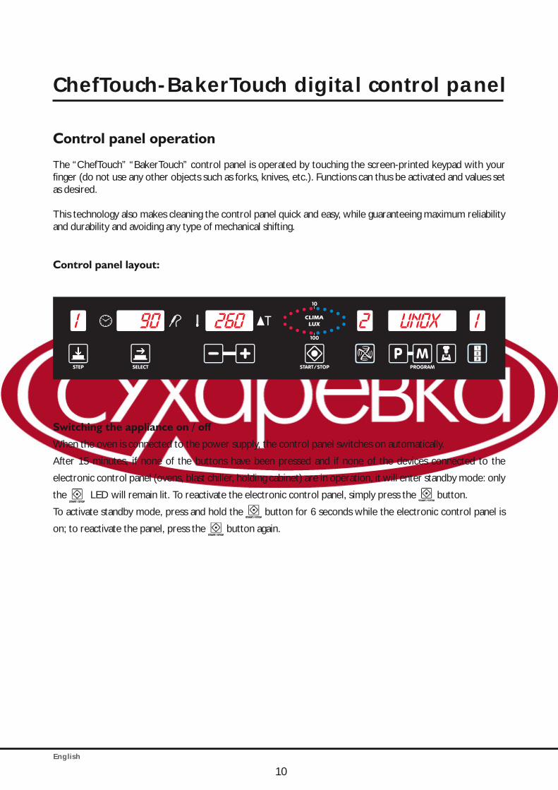
Control panel operation The “ChefTouch” “BakerTouch” control panel is operated by touching the screen-printed keypad with your finger (do not use any other objects such as forks, knives, etc.). Functions can thus be activated and values set as desired.
This technology also makes cleaning the control panel quick and easy, while guaranteeing maximum reliability and durability and avoiding any type of mechanical shifting.
Control panel layout:
Switching the appliance on / off
When the oven is connected to the power supply, the control panel switches on automatically.
After 15 minutes, if none of the buttons have been pressed and if none of the devices connected to the
electronic control panel (ovens, blast chiller, holding cabinet) are in operation, it will enter standby mode: only
the LED will remain lit. To reactivate the electronic control panel, simply press the button.
To activate standby mode, press and hold the button for 6 seconds while the electronic control panel is
on; to reactivate the panel, press the button again.
ChefTouch-BakerTouch digital control panel
English
BakerTop™ChefTop™
11
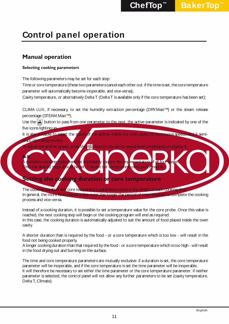
Manual operation
Selecting cooking parameters
The following parameters may be set for each step:Time or core temperature (these two parameters cancel each other out: if the time is set, the core temperature parameter will automatically become inoperable, and vice-versa);Cavity temperature, or alternatively Delta T (Delta T is available only if the core temperature has been set);
CLIMA LUX, if necessary, to set the humidity extraction percentage (DRY.Maxi™) or the steam release percentage (STEAM.Maxi™);Use the button to pass from one parameter to the next; the active parameter is indicated by one of the five icons lighting up.It is also possible to select the speed of the airflow inside the oven cavity (3 continuous speeds and 3 semi-static operating modes).To adjust the airflow speed, press the button; the active speed level is indicated on display 4.
N.B.A complete cooking cycle does not necessarily require the implementation of all four steps.Only the desired steps should be set. This will not compromise oven performance.
Setting the cooking duration or core temperature
The cooking duration and core temperature parameters control the length of each cooking step.In general, the more food placed in the oven, the longer the period of time required to complete the cooking process and vice-versa.
Instead of a cooking duration, it is possible to set a temperature value for the core probe. Once this value is reached, the next cooking step will begin or the cooking program will end as required.In this case, the cooking duration is automatically adjusted to suit the amount of food placed inside the oven cavity.
A shorter duration than is required by the food - or a core temperature which is too low - will result in the food not being cooked properly.A longer cooking duration than that required by the food - or a core temperature which is too high - will result in the food drying out and burning on the surface.
The time and core temperature parameters are mutually exclusive: if a duration is set, the core temperature parameter will be inoperable, and if the core temperature is set the time parameter will be inoperable.It will therefore be necessary to set either the time parameter or the core temperature parameter: if neither parameter is selected, the control panel will not allow any further parameters to be set (cavity temperature, Delta T, Climate).
Control panel operation
English
12
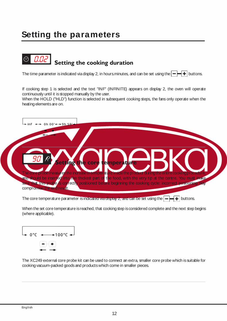
Setting the cooking duration
The time parameter is indicated via display 2, in hours.minutes, and can be set using the buttons.
If cooking step 1 is selected and the text "INF" (INFINITE) appears on display 2, the oven will operate continuously until it is stopped manually by the user.When the HOLD ("HLD") function is selected in subsequent cooking steps, the fans only operate when the heating elements are on.
inF 9h 59 '0h 00 '
Setting the core temperature
The core probe measures the increase in temperature inside the product during the entire cooking procedure, and should be inserted into the thickest part of the food, with the very tip at the centre. You must make sure that this probe is correctly positioned before beginning the cooking cycle: incorrect positioning may compromise the end result.
The core temperature parameter is indicated via display 2, and can be set using the buttons.
When the set core temperature is reached, that cooking step is considered complete and the next step begins (where applicable).
0°C 100°C
The XC249 external core probe kit can be used to connect an extra, smaller core probe which is suitable for cooking vacuum-packed goods and products which come in smaller pieces.
Setting the parameters

English
BakerTop™ChefTop™
13
Setting the cavity temperature or the Delta T value
The exact setting of the temperature inside the cavity ensures the food is cooked properly, both inside and outside.A lower temperature than the specified value dries the food out instead of cooking it.A higher temperature than the specified value burns the surface while the core remains uncooked (sometimes this is the desired result, especially where meat is concerned).Cooking with the DELTA-T parameter is only possible during cooking steps which use the core probe to control the cooking duration. By DELTA-T, we mean the difference between the temperature inside the oven cavity and the value detected by the core probe inside the product.The cavity temperature and Delta T parameters are mutually exclusive: if the cavity temperature is set, the Delta T parameter is inoperable, and if the Delta T is set, the cavity temperature parameter is inoperable.
Setting the parameters
Caution!Protect your arms and hands - Risk of injury!
Always position the core probe as instructed.Risk of damage!
Do not leave the probe hanging out of the oven cavity.Risk of damage!
Remove the probe from the food before taking the pan or the dish out of the oven. Risk of damage!
English
14
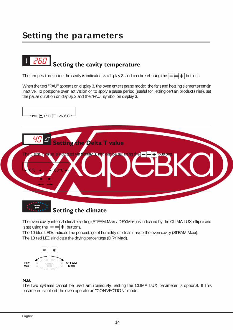
Setting the cavity temperature
The temperature inside the cavity is indicated via display 3, and can be set using the buttons.
When the text "PAU" appears on display 3, the oven enters pause mode: the fans and heating elements remain inactive. To postpone oven activation or to apply a pause period (useful for letting certain products rise), set the pause duration on display 2 and the "PAU" symbol on display 3.
- +PAU 0° C 260° C
Setting the Delta T value
The Delta T value is indicated via display 3, and can be set using the buttons.
0°C 100°C
Setting the climate
The oven cavity internal climate setting (STEAM.Maxi / DRY.Maxi) is indicated by the CLIMA LUX ellipse and is set using the buttons.The 10 blue LEDs indicate the percentage of humidity or steam inside the oven cavity (STEAM Maxi);The 10 red LEDs indicate the drying percentage (DRY Maxi).
STEAMM axi
DRYM axi
N.B.The two systems cannot be used simultaneously. Setting the CLIMA LUX parameter is optional. If this parameter is not set the oven operates in "CONVECTION" mode.
Setting the parameters
English
BakerTop™ChefTop™
15
Steam / Humidity release inside the oven cavity: STEAM.Maxi™
Your oven is equipped with exclusive STEAM.Maxi technology for the generation of steam inside the oven cavity. This innovative technology allows you to carry out any kind of steam cooking, starting from a temperature of 48°C, while guaranteeing maximum accuracy in terms of steam production temperature control.
STEAM.Maxi™ introduces adjustable amounts of steam in conjunction with various temperatures, allowing different types of cooking to take place:
• Steaming (only steam);• Mixed convection-steam cooking (air+steam).
Through the ADAPTIVE.Clima technology, BakerTop™ and ChefTop™ ovens constantly monitor all cooking parameters, not only in terms of temperature, but also the current humidity level inside the cavity. This ensures the most suitable cooking program is always applied, to help each user achieve perfect results every time, regardless of the number of trays placed inside.
The ADAPTIVE.Clima function will release the amount of steam required to create the humidity percentage set by the user.
Caution!During the cooking process, the product inside the oven releases a certain amount of steam: it may happen, therefore, that the appliance does not produce any steam, if the moisture released by the food is sufficient to achieve the value requested by the user. In this case the lack of steam production is not due to an appliance malfunction, but is the result of oven monitoring and control procedures taking place correctly.
To set the desired humidity level inside the oven cavity, proceed as follows:
• Press the button repeatedly until the CLIMA LUX display flashes;
• Use the button to set the desired steam release percentage (STEAM.Maxi™).
The 10 blue LEDs indicate the humidity percentage level inside the cavity requested by the user, which can
vary from 10% to 90% for each step in the cooking cycle. If 100% is selected - and for temperatures below
130°C - the oven will automatically activate its steam only mode.
Setting the parameters
English
16
Extracting humidity/steam from the oven cavity: DRY.Maxi™
The patented DRY.Maxi™ technology makes it possible to quickly extract all the humidity from the oven cavity, whether it was released by the products in the oven or generated by the STEAM.Maxi™ system in a previous cooking step.The DRY.Maxi™ technology means that ChefTop™ and BakerTop™ ovens guarantee enhanced flavours, whether cooking restaurant dishes or baking pastry and bread products.To set the desired humidity extraction level inside the oven cavity, proceed as follows: • Press the button repeatedly until the CLIMA LUX display flashes;• Use the button to set the desired humidity extraction percentage (DRY.Maxi™).The 10 red LEDs indicate the variable humidity percentage (between 10% and 100%) which needs to be extracted from the oven cavity.
Setting the airflow speedThe option of setting 3 airflow speeds inside the oven cavity, in addition to the 3 semi-static operating modes, means it is possible to cook any product, from delicate and light foods to those which require a great deal of heat. The button can be used to set the motor revolution speed and operating mode. There are 3 continuous revolution speeds and 3 semi-static operating modes.The semi-static mode only activates the motors when the heating elements are on, which accurately reproduces the effects of a traditional static oven. The fan is activated for a few moments, in order to evenly distribute the heat produced by the heating elements and to ensure the temperature remains uniform throughout the oven cavity. The speed selected previously is indicated on display 4 and can be selected using the button, in the following sequence:• 1: indicates that the revolution speed is set to minimum• 2: indicates that the revolution speed is between the minimum and maximum settings• 3: indicates that the revolution speed is set to maximum• 1P: indicates semi-static operation, with the revolution speed set to minimum• 2P: indicates semi-static operation, with the revolution speed set to the medium value• 3P: indicates semi-static operation, with the revolution speed set to maximum
Starting / stopping the cooking processOnce you have set all the cooking parameters, press
to start the cooking cycle.
To stop the cooking cycle, press the button again.
When the cooking cycle has finished, both in manual and programmed mode, the oven emits an audible alarm for 15 seconds and the display flashes for 45 seconds.During this 45-second period, the “START / STOP” LED remains on.If you press the button during this period, the set cooking time will be increased and the oven will automatically start again (using the most recent cooking parameters).If you press the button the “START / STOP” LED will switch off and all operating parameters will be reset.If none of the buttons are pressed within 45 seconds, the “START / STOP” LED will switch off and all operating parameters will be reset.
Setting the parameters
English
BakerTop™ChefTop™
17
Starting / stopping the cooking process
Selecting the cooking steps
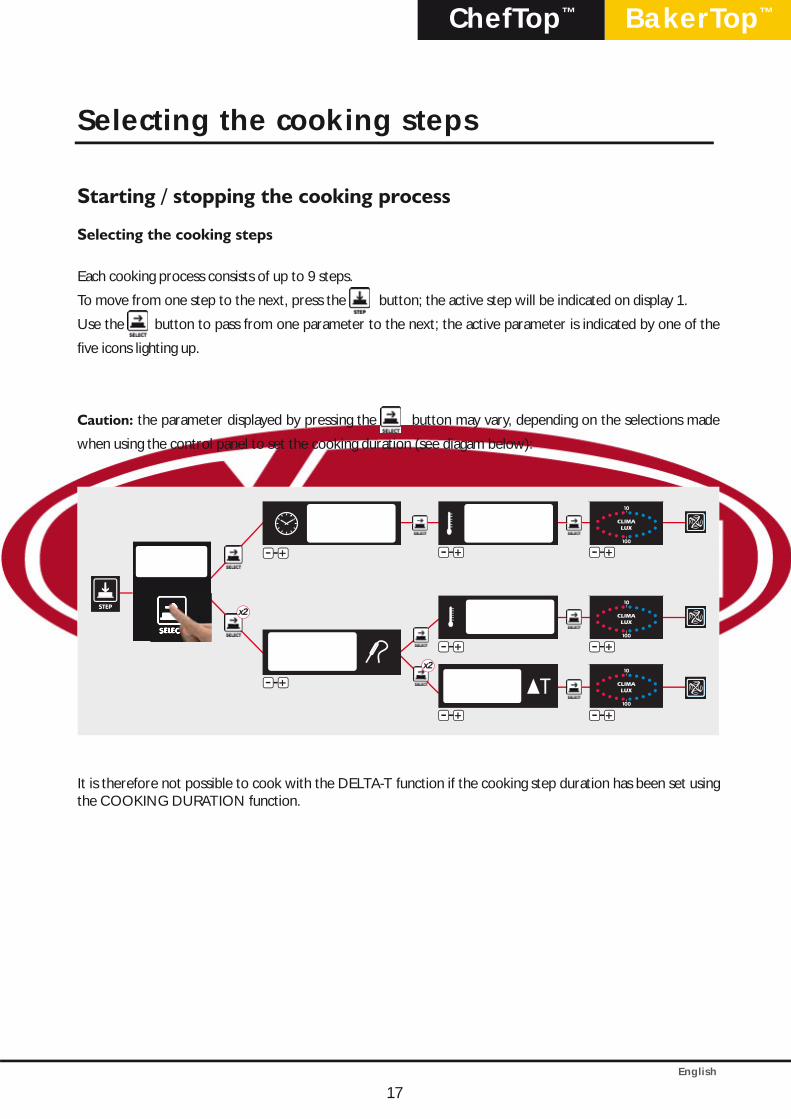
Each cooking process consists of up to 9 steps.
To move from one step to the next, press the button; the active step will be indicated on display 1.
Use the button to pass from one parameter to the next; the active parameter is indicated by one of the
five icons lighting up.
Caution: the parameter displayed by pressing the button may vary, depending on the selections made
when using the control panel to set the cooking duration (see diagam below):
- +-
x2
x2
- +-
- +-
- +-
- +-
- +-
- +-
- +-
It is therefore not possible to cook with the DELTA-T function if the cooking step duration has been set using the COOKING DURATION function.
Selecting the cooking steps
English
18
Cooking with a set duration and cavity temperature
First step:
Press the button until the timer display begins to flash ;
Use the - +- buttons to set the duration as desired.
- +
1° STEP
INF
INF 9h 59’ - +
2° 3° 4°... STEP
HLD
HLD 0h 00’ 9h 59’0h 00’
N.B. During cooking step 1, an indefinite duration "INF" may be set; in this case the oven will maintain the temperature and humidity parameters indefinitely and will have to be stopped manually by the user. During cooking steps 2/3/4, the "HLD" function may be selected in order to maintain a constant cavity temperature of 70°C until the oven is switched off manually; this keeps the food inside the oven hot and ready to be served.
Second step:
Press the button again, until the temperature display begins to flash;
Use the - +- buttons to set the desired cavity temperature.
- +PAU 0° C 260° C
N.B.The pause function, "PAU", may be selected at any time. During this time, the oven will remain in Standby mode, with the fans, heating elements and burner switched off. This is a useful function for many types of cooking, particularly if you wish to limit "Thermal pressure" on the product.
Third step:
CLIMA LUX, if necessary, with a humidity extraction percentage (DRY.Maxi™) or steam release percentage
(STEAM.Maxi™):
• Press the button again, until the CLIMA LUX display
begins to flash;
• Use the + button to set the desired steam release percentage (STEAM.Maxi™);
• Use the - button to set the desired humidity extraction percentage (DRY.Maxi™);
• Leave the setting as Ø for convection-only cooking, without releasing or extracting steam.
Fourth step:
To change the airflow speed, press the button;
the current speed level is indicated on display 4.
Setting the cooking programs
English
BakerTop™ChefTop™
19
Cooking with the core probe at a set oven cavity temperature
First step:
Press the button until the core temperature symbol begins to flash;
Use the - +- buttons to set the desired core temperature.
- +0° C 120° C
N.B.By setting the core temperature, the cooking duration is set automatically.As soon as the set core temperature is reached, the oven moves on to the following step (if selected) or the cooking cycle ends.
Second step:
Press the button again, until the temperature display begins to flash;
Use the - +- buttons to set the desired core temperature.
- +PAU 0° C 260° C
N.B.The pause function, "PAU", may be selected at any time. During this time, the oven will remain in Standby mode, with the fans, heating elements and burner switched off. This is a useful function for many types of cooking, particularly if you wish to limit "Thermal pressure" on the product.
Third step:
CLIMA LUX, if necessary, with a humidity extraction percentage (DRY.Maxi™) or steam release percentage
(STEAM.Maxi™):
• Press the button again, until the CLIMA LUX display begins to flash;
• Use the + button to set the desired steam release percentage (STEAM.Maxi™);
• Use the - button to set the desired humidity extraction percentage (DRY.Maxi™);
• Leave the setting as Ø for convection-only cooking, without releasing or extracting steam.
Fourth step:
To change the airflow speed, press the button;
the current speed level is indicated on display 4.
Setting the cooking programs

English
20
Cooking with the core probe at a set Delta T
First step:
Press the button until the core temperature symbol begins to flash;
Use the - +- buttons to set the desired core temperature.
- +0° C 120° C
N.B.By setting the core temperature, the cooking duration is set automatically.As soon as the set core temperature is reached, the oven moves on to the following step (if selected) or the cooking cycle ends.
Second step:
Press the button again, until the Delta T display begins to flash;
Use the - +- buttons to set the desired Delta T.
-0° C 260° C+
N.B.The oven will never, under any circumstances, operate at temperatures above 260�.
Third step:
CLIMA LUX, if necessary, with a humidity extraction percentage (DRY.Maxi™) or steam release percentage
(STEAM.Maxi™):
• Press the button again, until the CLIMA LUX display begins to flash;
• Use the + button to set the desired steam release percentage (STEAM.Maxi™);
• Use the - button to set the desired humidity extraction percentage (DRY.Maxi™);
• Leave the setting as Ø for convection-only cooking, without releasing or extracting steam.
Fourth step:
To change the airflow speed, press the button;
the current speed level is indicated on display 4.
Setting the cooking programs
English
BakerTop™ChefTop™
21
Operation using programs
The ChefTouch/BakerTouch electronic control panel allows the user to save up to 99 cooking programs, each assigned with a name up to 25 letters long.
Access the programming menu by pressing the button;
Select the location in which you wish to save the program (from P01 to P99) using the - +- buttons indicated
on display 5; press and use the - +- buttons to select the first letter of the name as desired;
Press again and use the - +- buttons to select the second letter;
Repeat this procedure for subsequent letters;
Finally, press the button to select the oven preheating temperature. The text "PRE" will appear;
Use the button to select either an absolute preheating temperature or a temperature difference
between the preheating value and the value for the first cooking step of program;
Use - +- to set the desired value, expressed in degrees;
Press the button to move to the next step and set the desired operating parameters (Duration, Core
Temperature, Cavity Temperature, Delta T, Climate) for the step;
Press the button and set the parameter governing airflow speed inside the oven cavity;
Press and hold the button for 5 seconds to store the program in the memory (after 5 seconds a confirmation
beep will sound).
Using saved programs:
Access the programming menu by pressing the button;
Press the - +- buttons until the number correpsonding to the desired program appears on display 5;
Press the button to start the selected program;
Press the button again to stop the program.
N.B.When a saved cooking program is started, the oven preheats automatically to the setted preheating temperature.When a cooking program is started, the oven begins the set preheating step. During this step, all the LEDs and displays remain off except the "START / STOP" LED, display 2 (which shows the text "PRE") and display 4 (which indicates the program being used). When the desired temperature has been reached and is maintained, the oven beeps and the data corresponding to the first cooking step appears on the display. After the door has been opened, the food placed inside and the door closed again, the cooking program begins automatically.
User programming procedures SH
OR
T W
ASH
ING
LH2O
WA
SHIN
G
CO
OL
SEM
I-AU
TO W
ASH
ING
RES
TAR
T
LAST
P
P01
P02 ... P99
MED
WA
SHIN
G
LON
G W
ASH
ING
PUM
P LO
AD
ING P
- +

English
22
LASTP functionThis can be used to quickly select the most recently used cooking cycle, whether it was activated manually or in programmed mode.When the cooking cycle has finished, press the button. The text "LASTP" will appear on display 5; Press the button to start the most recently used cooking cycle again.
Automatic washing programs
The Rotor.KLEAN™ washing system, code XC405, offers automatic washing of the oven cavity. Automatic washing programs can only be used if the appliance features this option. The Rotor.KLEAN™ washing system may also be installed after the appliance has been commissioned.3 washing programs (SHORT WASHING, MED WASHING and LONG WASHING) are stored in the control P.C.B. memory, as well as a pre-loading program for the detergent and rinse aid pipes (PUMP LOADING).There are another two semi-automatic programs: "LH2O", which can be used to rinse and dry the oven cavity at a temperature of 120°C, without the use of chemicals and “SEMI-AUTOMATIC WASHING” which can wash the oven cavity using a pre setted temperature and chemicals products manually.Access the programming menu by pressing the button;Press the - +- buttons repeatedly until the LH2O, SHORT WASHING, MED WASHING, LONG WASHING or PUMP LOADING washing programs appear on display 5;Press the button to start the selected program;
N.B.The first time the washing system is used, it is advisable to run the PUMP LOADING program to remove any air inside the detergent and rinse aid pipes, so that the quality of the wash is not compromised.These programs are only used if the Rotor.KLEAN™ washing system (XC405) is installed.
Caution!Never open the oven cavity door while a cleaning cycle is in progress - chemical cleaning substances and hot air may escape - risk of corrosion and burns! When the cleaning cycle implemented by the Rotor.KLEAN™ system is complete, make sure that there is no detergent residue remaining in the oven cavity (including the area behind the air channel panelling). Remove any residue and rinse the entire oven cavity thoroughly (including the area behind theair channel panelling) using a hand-held shower head - risk of corrosion!
Standard functions
Caution!We recommend the oven cavity is cleaned on a daily basis, in order to maintain acceptable hygiene standards and to prevent the stainless steel inside the cavity from being ruined. We would therefore recommend the use of the Rotor.KLEAN™ washing system, code XC405, which offers automatic washing of the oven cavity. Caution!If the appliance is not cleaned or not cleaned thoroughly enough, grease or remnants of food which have accumulated inside the oven cavity may start to burn - fire hazard!To prevent corrosion from occurring inside the oven cavity, the appliance should be cleaned every day, even if it is only used for steam cooking purposes. Only use detergents which have been recommeded by the appliance manufacturer. Detergents from other manufacturers may damage the appliance and therefore invalidate the guarantee.
English
BakerTop™ChefTop™
"COOL" program for oven cavity cooling
The “COOL” program is used for oven cavity cooling; it allows the fans inside the cavity to rotate whilst the heating elements remain off. The program can also be started with the door open, to accelerate the cavity cooling process. During this program, the temperature inside the oven cavity is displayed.
• Access the programming menu by pressing the button;• Press the - +- buttons until the LCOOL program appears on display 5;• Press the button to start the selected program.
23
Standard functions
English
24
ADAPTIVE.Clima function*
Through the ADAPTIVE.Clima technology, ChefTop™ and BakerTop™ ovens constantly monitor all cooking parameters, not only in terms of temperature, but also the current humidity level inside the cavity. This ensures the most suitable cooking program is always applied, to help each user achieve perfect results every time, regardless of the number of trays placed inside.
The amount of steam released inside the oven cavity varies in accordance with the amount of food placed inside the appliance, even when the same program is used. As a general rule, the greater the amount of food placed inside the oven, the less steam will be produced by the oven.
The ADAPTIVE.Clima technology can also be used to store the most recently used cooking process in the memory of the appliance. For this use we recommend to use the MULTI.Point core probe in order to prevent positioning mistakes.The constant monitoring of all cooking parameters allows ChefTop™ and BakerTop™ ovens to acquire information regarding changes in the temperature and humidity level during the entire cooking process, while gathering information on the effects of any manual interventions from the user (opening the door, for example).Once the desired result has been achieved, the ADAPTIVE.Clima technology also allows the user to store the implemented process in the memory of the appliance so that it can be repeated as often as necessary in the knowledge that the results will always be the same, without any user intervention or supervision being required.The oven will automatically reproduce the effects of the user's actions during the "pilot" process (the one you wish to repeat): if, for example, the door was opened in the third minute, causing the temperature to drop by 20°C and the humidity inside the cavity to disperse, the oven will also simulate these effects in the subsequent cooking processes.
Caution: to store an ADAPTIVE.Clima program in the memory correctly, the core probe must have been inserted correctly during the “pilot” cooking process, even if the program set on the control panel did not require its application.
To store the cooking process you have just completed in the memory of the appliance using the ADAPTIVE.Clima technology, proceed as follows:
• At the end of the cooking process, press the button;
• Use the + button to select the program memory slot in which you would like to store the “pilot” cooking
process. For example A.C01, A.C02, …
• Press and use the - +- buttons to select the first letter of the name you wish to assign to the
program;
• Press again and use the - +- buttons to select the second letter;
• Repeat this procedure for subsequent letters;
• Press and hold the button for 5 seconds to store the program in the memory (after 5 seconds a
confirmation beep will sound).
Caution: it is not possible to modify any of the parameters for a stored ADAPTIVE.Clima program.
Standard functions
English
BakerTop™ChefTop™
25
ChefUnox - BakerUnox automatic cooking processes
The ChefTouch - BakerTouch digital control panel has a set of suggested automatic cooking settings devised by ChefUnox - BakerUnox stored in its memory.Simply select the desired type of cooking to automatically prepare an endless range of foods.Every type of automatic cooking program offers the option of customising certain parameters, in order to achieve the optimal level of browning and cooking in line with your own requirements.
• Press the button;• Use the - button to select the desired program;• Press the button to start the program;• Press the button again to stop the program.
N.B.Before starting the program, you may change the value of a parameter which can be used to adjust the cooking level as desired. The oven will adjust its cooking performance accordingly, in order to gurantee a perfect result.
• Press the button until the parameter you want to modify flashes;
• Use the - +- buttons to set the new value as desired.
If you want to make this change permanent:
• Press and hold the button for 5 seconds (you will then hear a beep to indicate the program has been saved).
DESCRIPTIONADJUSTABLE PARAMETER
WHEN TO INCREASE WHEN TO DECREASE
ROASTING Roasting meats Core probe 54°C Increase the cooking level Decrease the cooking level
CRISPY ROAST Roasting meats with a crust Core probe 54°C Increase the cooking level Decrease the cooking level
NIGHT ROAST Roasting meats overnight Core probe 54°C Increase the cooking level Decrease the cooking level
BRAISE Braising and stewing meats Cooking time 1 h Increase the cooking level Decrease the cooking level
GRILL Grilling vegetables and meats9 Timers can be set, use
FAKIRO Grill - -
MULTI TIMESimultaneous cooking of
several products for various periods of time
Set temperature and CLIMALUX, press Start and use the step button to set the
9 timers
- -
CHICKENCooking chicken, birds,
poultry, gameTime 5 min Increase external browning Decrease external browning
ROAST POTATO Roast potatoes Time 5 min Increase external browning Decrease external browning
BAKING Cooking frozen baked goods Time 5 min Increase the cooking level Decrease the cooking level
+3 REGEN Regeneration from 3°C Core probe 65°CIncrease the temperature of
the dish for serviceDecrease the temperature
of the dish for service
Pre-set cooking procedures
English
26
MAXI.Link technology:controlling several appliances using the same control panel
The ChefTouch – BakerTouch digital control panel allows the user to control a variety of UNOX ChefTop™ - BakerTop™ appliances connected to the oven. The MAXI.Link technology also allows the user to control several ovens with a single digital control panel. The oven used to control all the other appliances becomes the MASTER oven. The ovens controlled by the MASTER oven become SLAVE ovens, and their digital control panels remain inactive. The MASTER and SLAVE digital control panels are interchangeable in the event of an emergency.
The appliance to be controlled is selected using the button; this selection is indicated by display 6.
Number / appliance correspondence table
ChefTop™
Appliance number Appliance code Device1 ChefTop™ master oven2 ChefTop™ slave oven 1 3 ChefTop™ slave oven 24 ChefTop™ slave oven 35 XK305 Blast chiller6 XVL575 - XVL375 Holding cabinet / Slow cooking oven7 XC235 Reverse osmosis system9 XC236 Kit OVEX.Net 2.0
BakerTop™
Appliance number Appliance code Device1 Forno BakerTop™ master2 Forno BakerTop™ slave 1 3 Forno BakerTop™ slave 24 Forno BakerTop™ slave 36 XL405 Prover7 XC235 Reverse osmosis system
9 XC236 Kit OVEX.Net 2.0
MAXI.Link technology
English
BakerTop™ChefTop™
27
Chef’s recommendations for even cooking
PreheatingIt is always better to preheat the oven to a temperature at least 30-50°C higher than is required for cooking, in order to reduce the effects of heat lost when opening the door.The oven may be preheated to 300°C.Do not heat the oven to a temperature over 260°C for periods of longer than 10 minutes.
Tray typesTo achieve perfect cooking quality and even browning of the product, it is better not to use recipients which are too tall and prevent correct air circulation.
Tray spacingFor even cooking it is important to make sure there is at least 3 cm of free space between the product once it has risen and the tray above.
Quantity of foodTo achieve the best results, it is important not to overload the oven; you should also make sure, when baking bread and pastry, the food on the trays is facing the right direction in relation to the airflow.
Core probe positioningFor correct operation, it is essential that the core probe is inserted from top to bottom, at the thickest point of the food, until the tip reaches the centre.When cooking thinner foods, the core probe should be inserted horizontally to the support surface.
Be careful when opening the door!!!Heat and steam could cause burns.
Cooking principles
English
The digital control panel used in ChefTop™ - BakerTop™ ovens is designed to offer a straightforward interface between the oven and the outside world, by means of existing communication systems and those to be used in the future: USB, Bluetooth, serial port etc.
The USB XC236 interface kit can be used to carry out the following functions:• entering cooking programs• modifying operating parameters (e.g. probe calibration)• diagnosing malfunctions• storing oven cavity or blast chiller temperature changes in the memory of the appliance (data required for the HACCP system)Further information is supplied with the kit.
Warning messages:When a malfunction is detected which allows the appliance to continue operating, abeit in a limited manner, a WARNING message is displayed.The device continues to run and the WARNING message remains on the display until the button is pressed.
Warning messages oven:
Display message Description Effect Problem solution
WF01 An error has been detected in the data recorded by cavity probe 1
The oven contines to operate, using the data from cavity probe 2 only
Contact the Customer Assistance Service
WF02 An error has been detected in the data recorded by cavity probe 2
The oven contines to operate, using the data from cavity probe 1 only
Contact the Customer Assistance Service
WF03 An error has been detected in the data recorded by the core probe
It is not possible to set steps or activate programs which use the core probe; if a stepwhich uses the core probe is in progress, the following step will begin
Contact the Customer Assistance Service
WF04 Non correct fan rotation speed Turn off the motor breaking system Contact the Customer Assistance Service
WF05 An error has been detected in the cooling system for the electronic components
The cooling fan for the electronic components may not work
Contact the Customer Assistance Service
WF06 The temperature of the oven power P.C.B. is too high
There is a risk of permanentdamage to the power P.C.B.
Make sure the positioning standards specified in the installation manual have been observed. Contact the Customer Assistance Service
WF08 Gas board detected while the oven is set as electricThe oven keeps on working but is controlled as electric
Contact the Customer Assistance Service
WF09 Error on the motor breaking systemThe oven keeps on operating but the motor breaking system is not working
Contact the Customer Assistance Service
WF10 Non basic power board setting errorThe oven keeps on working (with some limitations due to the setting involved on the error)
Contact the Customer Assistance Service
WF11 Not correct temperature on the gas board The oven keeps on operating Contact the Customer Assistance Service
WF12 Too high temperature on the external thermocouples board
The oven keeps on operating Contact the Customer Assistance Service
WF13 The external sous-vide probe takes non correct dataThe oven keeps on working but it is not possible to use external sous-vide probe
Contact the Customer Assistance Service
WF14 Error on the data taken by the Multi.point core probe (totally not working)
The oven keeps on working but it is not possible to use cooking programs with the core probe
Contact the Customer Assistance Service
WF15 Error on the board-thermocouples communication system
The oven keeps on working but it is not possible to use external sous-vide probe
Contact the Customer Assistance Service
WF17 Error on the data taken by the Multi.point core probe (partially not working)
The oven keeps on working but the core temperature may be not precisely taken
Contact the Customer Assistance Service
28
Oven-user communication
English
BakerTop™ChefTop™
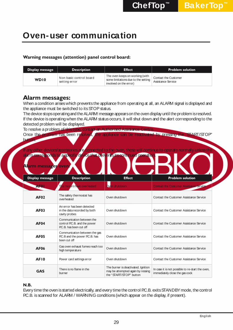
Warning messages (attention) panel control board:
Display message Description Effect Problem solution
WD10 Non basic control board setting error
The oven keeps on working (with some limitations due to the setting involved on the error)
Contact the CustomerAssistance Service
Alarm messages:When a condition arises which prevents the appliance from operating at all, an ALARM signal is displayed and the appliance must be switched to its STOP status.The device stops operating and the ALARM! message appears on the oven display until the problem is resolved. If the device is operating when the ALARM status occurs, it will shut down and the alert corresponding to the detected problem will be displayed.To resolve a problem of this type, contact an Authorised Assistance Centre.Once the problem has been resolved, the appliance can be reactivated by pressing the "START/STOP" button.
If any other devices/accessories are connected to the oven, these will continue to operate normally unless the alarm corresponds to a specific device that prevents its continued operation.
Alarm messages oven:
Display message Description Effect Problem solution
AF01 The motors have overheated Oven shutdown Contact the Customer Assistance Service
AF02 The safety thermostat hasoverheated
Oven shutdown Contact the Customer Assistance Service
AF03 An error has been detectedin the data recorded by bothcavity probes
Oven shutdown Contact the Customer Assistance Service
AF04 Communication between thecontrol P.C.B. and the powerP.C.B. has been cut off
Oven shutdown Contact the Customer Assistance Service
AF05Communication between the gas P.C.B and the power P.C.B. has been cut off
Oven shutdown Contact the Customer Assistance Service
AF06 Gas oven exhaust fumes reach too high temperature
Oven shutdown Contact the Customer Assistance Service
AF10 Power card settings error Oven shutdown Contact the Customer Assistance Service
GAS There is no flame in theburner
The burner is deactivated. Ignition may be attempted again by ressing the “START/STOP” button
In case it is not possible to re-start the oven, immediately close the gas cock
N.B.Every time the oven is started electrically, and every time the control P.C.B. exits STANDBY mode, the control P.C.B. is scanned for ALARM / WARNING conditions (which appear on the display, if present).
Oven-user communication
29
English
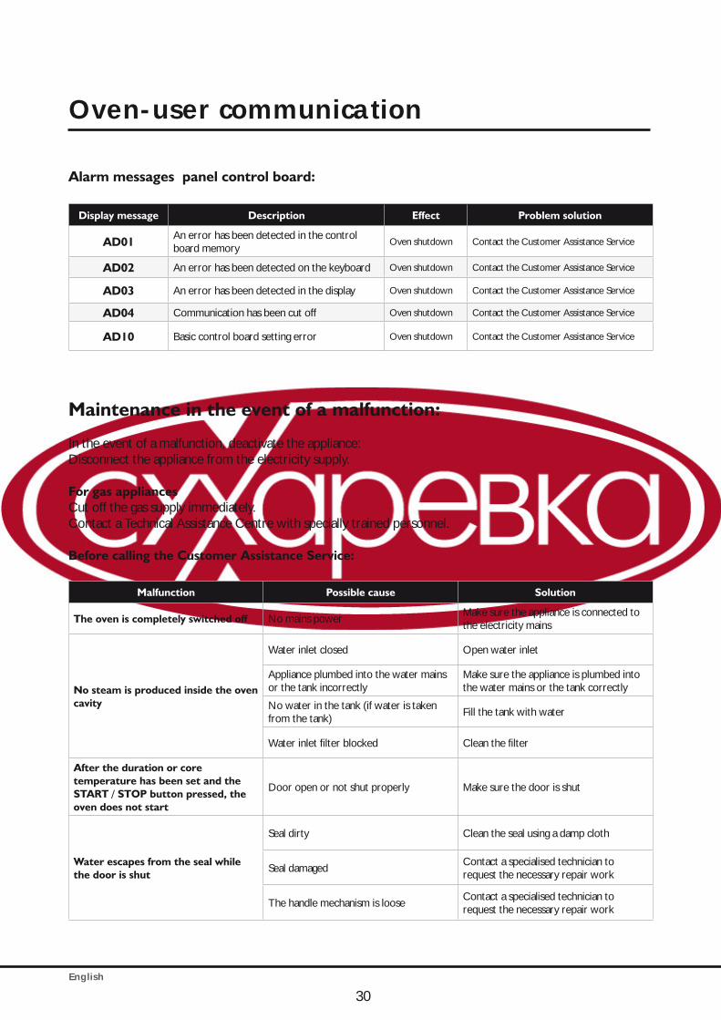
Alarm messages panel control board:
Display message Description Effect Problem solution
AD01 An error has been detected in the control board memory
Oven shutdown Contact the Customer Assistance Service
AD02 An error has been detected on the keyboard Oven shutdown Contact the Customer Assistance Service
AD03 An error has been detected in the display Oven shutdown Contact the Customer Assistance Service
AD04 Communication has been cut off Oven shutdown Contact the Customer Assistance Service
AD10 Basic control board setting error Oven shutdown Contact the Customer Assistance Service
Maintenance in the event of a malfunction:
In the event of a malfunction, deactivate the appliance:Disconnect the appliance from the electricity supply.
For gas appliancesCut off the gas supply immediately.Contact a Technical Assistance Centre with specially trained personnel.
Before calling the Customer Assistance Service:
Malfunction Possible cause Solution
The oven is completely switched off No mains powerMake sure the appliance is connected to the electricity mains
No steam is produced inside the oven cavity
Water inlet closed Open water inlet
Appliance plumbed into the water mains or the tank incorrectly
Make sure the appliance is plumbed into the water mains or the tank correctly
No water in the tank (if water is taken from the tank)
Fill the tank with water
Water inlet filter blocked Clean the filter
After the duration or core temperature has been set and the START / STOP button pressed, the oven does not start
Door open or not shut properly Make sure the door is shut
Water escapes from the seal while the door is shut
Seal dirty Clean the seal using a damp cloth
Seal damagedContact a specialised technician to request the necessary repair work
The handle mechanism is looseContact a specialised technician to request the necessary repair work
Oven-user communication
30
English
BakerTop™ChefTop™
Safety regulations
All installation, assembly, assistance and maintenance procedures must be performed by qualified personnel in accordance with current regulations.These technicians must, nevertheless, be aware of and apply the regulations relating to the safety of repaired products and safety in the workplace. Appliance installation by qualified personnel not authorised by UNOX will invalidate the guarantee. In light of the above information, UNOX accepts no responsibility for any situation resulting from work carried out in an unprofessional manner, or from the incorrect intepretation or application of regulations or the instructions supplied in this manual.
Caution!Incorrect installation, assistance, maintenance or cleaning procedures, or any modifications made to the appliance, may damage property or result in injury or even fatal accidents.Read the installation instructions carefully before installing the appliance.This appliance may only be used to cook food in industrial kitchens.Any other application does not conform to the specified use and is therefore considered hazardous.
Gas appliances onlyIf the appliance is installed below a cooker hood, the hood should be switched on while the operation.If the appliance is connected to a flue, the exhaust hose should be cleaned in accordance with (For further information, please contact your installer).Do not place any objects on top of the exhaust gas hose connected to the appliance - Fire hazard!The area underneath the appliance should not be blocked or obstructed by any objects - Fire hazard!The appliance may only be operated in a draught-free environment - Fire hazard!
If you smell gas:Cut off the gas supply immediately;Do not touch any of the electrical switches;Make sure the room is well ventilated;Avoid the creation of naked flames and sparks;Use a telephone outside the building and inform your gas supplier immediately.------Read the manual carefully before installing and commissioning the appliance. Make sure the appliance has not been damaged during the transportation process.If you suspect any damage may have occurred during transportation, inform your local authorised dealer or the shipping agent.
When disposing of the exhausted appliance, do not use normal waste channels or containers for worn-out household appliancesUNOX is part of the Valere consortium, a national organisation for the recovery of professional hospitality equipment, and will be happy to help you dispose of the appliance in the correct manner.
31
INSTRUCTIONS FOR THE INSTALLER

English
Make sure the unit will fit through all doors, corridors or other passageways required to reach the installation site.The table lists the measurements of the models, with and without packaging:
UNIT/MODEL No packagingLxDxH mm
With packagingLxDxH mm
UNIT/MODEL No packagingLxDxH mm
With packagingLxDxH mm
ChefTop™ electric ChefTop™ gas
XVC 055 574x737x498 740x800x640 - - -
XVC 105/ 105P 750x782x498 880x880x640 - - -
XVC 205 574x758x632 740x800x780 - - -
XVC 305/ 305P 750x792x625 880x880x780 XVC 315G 750x796x840 870x870x1000
XVC 505/ 505P 750x792x813 880x880x970 XVC 515G 750x796x1028 870x870x1200
XVC 705/ 705P 750x792x960 880x880x1120 XVC 715G 750x796x1175 870x870x1400
XVC 1005P/ 905P 866x972x1866 980x1140x2000 XVC 1015G/ 915G 866x970x2072 980x1140x2250
XVC 1205 860x1160x888 990x990x1300 XVC 1215G 860x1160x1028 -
XVC 2005 860x1160x1208 980x1300x1310 XVC 2015G 860x1160x1348 -
XVC 4005P/ 3205P 869x1206x1857 985x130x2000 XVC 4015G/ 3215G 869x1206x2072 -
BakerTop™ electric BakerTop™ gas
XBC 405 860x900x624 980x1060x772 - - -
XBC 605 860x900x820 980x1060x960 XBC 615G 860x900x1028 950x1030x1180
XBC 805 860x900x1140 980x1060x1280 XBC 815G 860x900x1348 980x1060x1470
XBC 1005/ 905 866x972x1866 980x1140x2000 XBC 1015G/ 915G 866x970x2072 980x1140x2250
The appliance should only be transported using pallets supplied by UNOX.
Caution!
Make sure that the appliance is not in danger of tipping over during transportation.Take the weight of the appliance into account. Use suitable supports.Wear protective shoes during the installation process.
32
Instructions for appliance transportation

English
BakerTop™ChefTop™
Oven installation is divided into 5 stages:
1) Preliminary and positioning procedures2) Electrical connection / Gas connection3) Plumbing: water supply4) Plumbing: water drainage5) Smoke exhaust outlet
2
3
5
1
41. Posizionamento2. Collegamento elettrico3. Acqua in ingresso4. Acqua in uscita5. Uscita fumi
Preliminary and positioning procedures
Installation siteBefore positioning the appliance, check the measurements and the exact position of the electrical, plumbing and smoke exhaust connections, in accordance with the figures provided in the enclosed "Technical Data" booklet.
Caution!Do not install the appliance near flammable materials.If the appliance is positioned near walls, partitions, kitchen cabinets, decorative trim, etc., these items must be made from non-flammable material. If this is not the case, they must be coated with a non-flammable heat insulating material, and all fire prevention regulations must be strictly observed.
33
Appliance installation
English
Removing the protective filmCarefully remove the protective film from the outer surfaces of the appliance, so that no glue residue is left behind. Any remaining residue can be removed using a suitable solvent product.
Removing the protective silicone from the tip of the core probe
Fitting the fixed appliance feetThe feet supplied in the bag inside the packaging ensure sufficient airflow for the cooling of electronic components and the outer surfaces of the oven. It is therefore essential that they are fitted correctly. Install the feet at the points indicated in the illustration. Caution! Do not use the oven without feet; this could cause the electronic components to overheat, damaging them beyond repair.
Drip drawerThe drip drawer fixed to the back panel of the oven collects any liquids deposited on the inside of the oven door, thereby preventing them from dripping onto the floor when the door is opened.
Remove the drip drawer from the rear of the oven using a screwdriver, slide the runners (supplied in the bag inside the oven) into position and insert the drawer as illustrated in the figure.
34
Appliance installation
English
BakerTop™ChefTop™
Warning
Position the appliance so that the back panel is easily accessible when performing electrical connection and carrying out maintenance work. The appliance is not suitable for recessed installation, or for use as part of a series of appliances. A minimum gap of 50 mm must be left around the entire perimeter of the appliance.If any fryers or other potential sources of hot liquid spills are used in the kitchen, they should be placed at least 45 cm away from the sides and 70 cm away from the back of the oven.
450 mm 700 mm50 mm
50 mm
For safety reasons, tabletop appliances must only be placed on supporting structures or cabinets from the appliance manufacturer. The maximum operating height for the top shelf level is 1600 mm.
1600 mm
The safety labels «max. height of thelast shelf for containers holding liquids» can be found in the starter kit.After installing theappliance, apply thelabel at aheight of 1600 mm.(see example)
Tabletop ovens require the use of special stands, leavening devices or tray racks, or should be placed on top
of a stainless steel table.
Do not install ovens directly on the floor.
35
Trolley ovens, positioning layout
English
Align the appliance horizontally.
Make sure the appliance is level.
During cooking, hot smoke is produced, along with other odours which need to be removed from the flue; it is therefore advisable to position the oven underneath a suitable cooker hood, or to use the special UNOX hoods and ensure the fumes are channelled outside.
36
Positioning
English
BakerTop™ChefTop™
Positioning
Door closure regulation
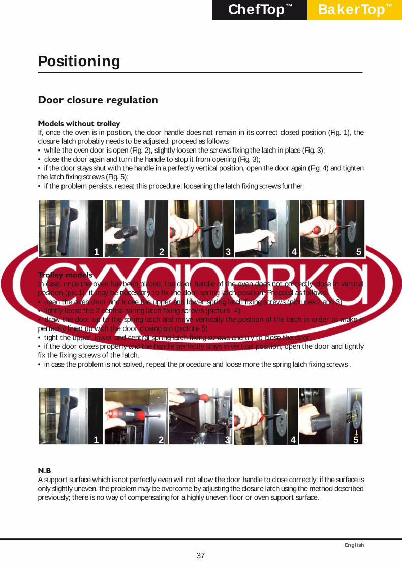
Models without trolleyIf, once the oven is in position, the door handle does not remain in its correct closed position (Fig. 1), the closure latch probably needs to be adjusted; proceed as follows:• while the oven door is open (Fig. 2), slightly loosen the screws fixing the latch in place (Fig. 3); • close the door again and turn the handle to stop it from opening (Fig. 3);• if the door stays shut with the handle in a perfectly vertical position, open the door again (Fig. 4) and tighten the latch fixing screws (Fig. 5);• if the problem persists, repeat this procedure, loosening the latch fixing screws further.
2 3 4 51
Trolley modelsIn case, once the oven has been placed, the door handle of the oven does not correctly close in vertical position (pic.1), it may be necessary to fix the door spring latch position. Proceed as follows:• open the oven door and loose the upper and lower spring latch fixing screws (pictures 2 and 3)• lightly loose the 2 central spring latch fixing screws (picture 4)• draw the door up to the spring latch and move vertically the position of the latch in order to make it perfectly lined up with the door closing pin (picture 5)• tight the upper, lower and central spring latch fixing screws and try to close the door.• if the door closes properly and the handle perfectly stays in vertical position, open the door and tightly fix the fixing screws of the latch.• in case the problem is not solved, repeat the procedure and loose more the spring latch fixing screws .
2 3 4 51
N.BA support surface which is not perfectly even will not allow the door handle to close correctly: if the surface is only slightly uneven, the problem may be overcome by adjusting the closure latch using the method described previously; there is no way of compensating for a highly uneven floor or oven support surface.
37
English
The support surface must be flat and level. The installation site must be able to withstand the weight of the appliance and the maximum load. Please refer to the table below:
UNIT/MODEL Weight (without load) UNIT/MODEL Weight (without load)
ChefTop™ elettrici ChefTop™ gas
XVC 055 35 kg - -
XVC 105/ 105P 45 kg - -
XVC 205 41 kg - -
XVC 305/ 305P 59 kg XVC 315G 73 kg
XVC 505/ 505P 76 kg XVC 515G 90 kg
XVC 705/ 705P 83 kg XVC 715G 97 kg
XVC 1205 150 kg XVC 1215G 170 kg
XVC 2005 165 kg XVC 2015G 185 kg
BakerTop™ elettrici BakerTop™ gas
XBC 405 60 kg - -
XBC 605 86 kg XBC 615G 106 kg
XBC 805 118 kg XBC 815G 132 kg
Once the appliance has been positioned, make sure that there is no danger of it slipping or tipping over.
Caution!If the appliance is to be mounted on a mobile support frame or cabinet, it should be secured with an extra chain or rope to stop it from rolling around and damaging the electricity or gas supply lines.
Positioning
38
English
BakerTop™ChefTop™
Trolley models
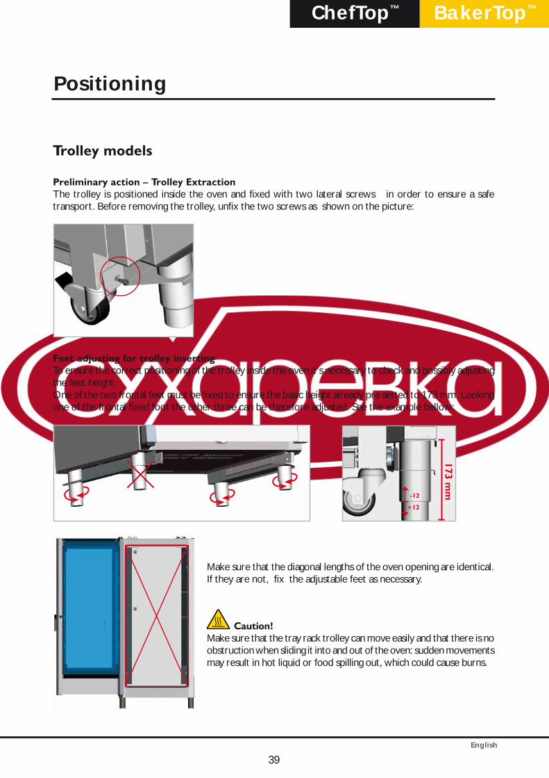
Preliminary action – Trolley ExtractionThe trolley is positioned inside the oven and fixed with two lateral screws in order to ensure a safe transport. Before removing the trolley, unfix the two screws as shown on the picture:
Feet adjusting for trolley insertingTo ensure the correct positioning of the trolley inside the oven it’s necessary to check and possibly adjusting the feet height.One of the two frontal feet must be fixed to ensure the basic height already pre setted to 173 mm. Looking one of the frontal fixed foot the other three can be therefore adjusted. See the example bellow:
173 mm
-12
+12
Make sure that the diagonal lengths of the oven opening are identical. If they are not, fix the adjustable feet as necessary.
Caution!Make sure that the tray rack trolley can move easily and that there is no obstruction when sliding it into and out of the oven: sudden movements may result in hot liquid or food spilling out, which could cause burns.
Positioning
39
English
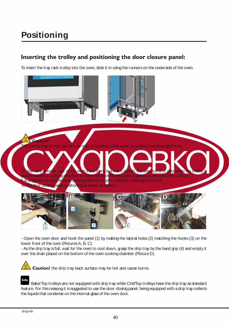
Inserting the trolley and positioning the door closure panel:
To insert the tray rack trolley into the oven, slide it in using the runners on the underside of the oven.
Caution!The trolley may be hot, and should only be handled while wearing suiable protective garments.
On the central lower part of the oven front there is a micro switch; the oven turns of only when the trolley is placed inside the cooking chamber or when the door closing panel is placed as described here above. It is suggested to use the door closing panel during pre-heating or washing programs. To the door closing panel positioning proceed as follows:
AA BB CC DD
1
3
2 4
- Open the oven door and hook the panel (1) by making the lateral holes (2) matching the hooks (3) on the lower front of the oven (Pictures A, B, C).- As the drip tray is full, wait for the oven to cool down, grasp the drip tray by the hand grip (4) and empty it over the drain placed on the bottom of the oven cooking chamber (Picture D).
Caution! the drip tray back surface may be hot and cause burns.
BakerTop trolleys are not equipped with drip tray while ChefTop trolleys have the drip tray as standard feature. For this reasong it is suggested to use the door closing panel, being equipped with a drip tray collects the liquids that condense on the internal glass of the oven door.
40
Positioning
English
BakerTop™ChefTop™
Caution!
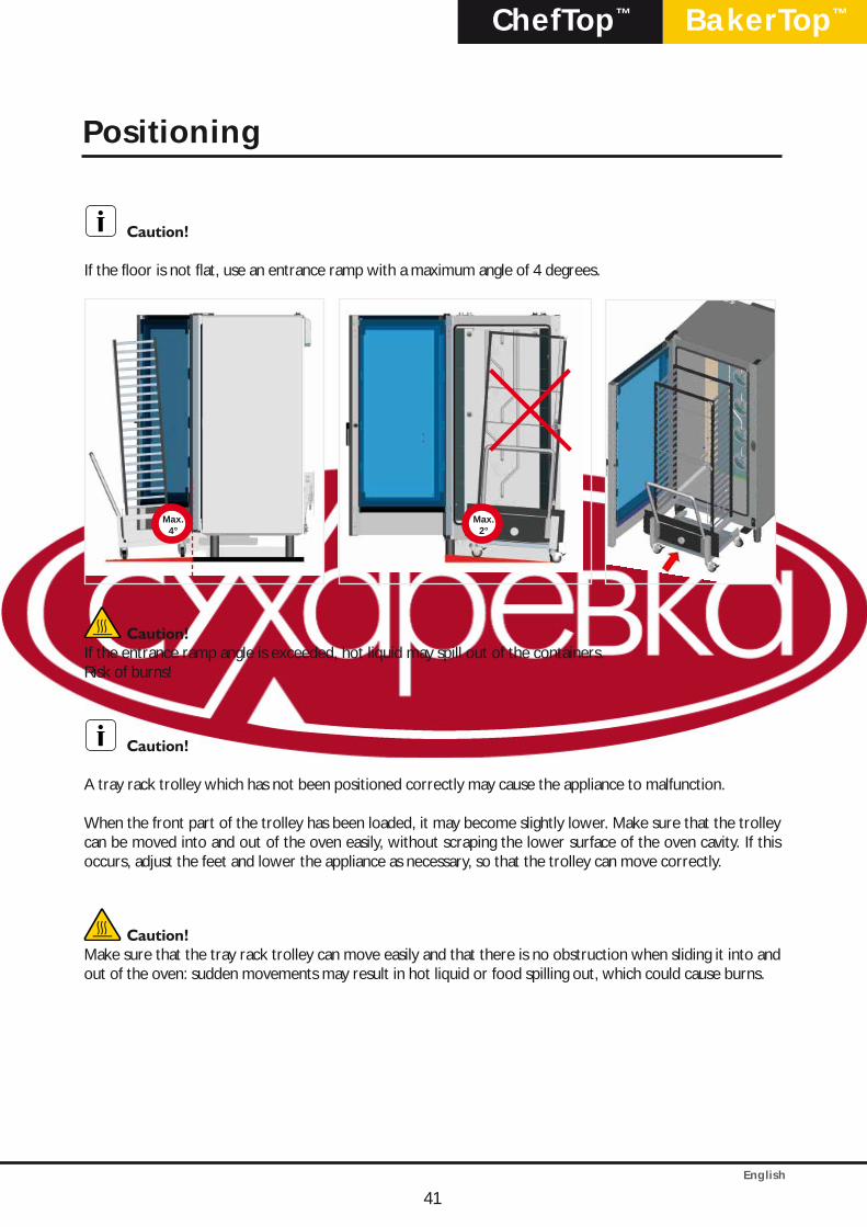
If the floor is not flat, use an entrance ramp with a maximum angle of 4 degrees.
Max.4°
Max.2°
Caution!If the entrance ramp angle is exceeded, hot liquid may spill out of the containers.Risk of burns!
Caution!
A tray rack trolley which has not been positioned correctly may cause the appliance to malfunction.
When the front part of the trolley has been loaded, it may become slightly lower. Make sure that the trolley can be moved into and out of the oven easily, without scraping the lower surface of the oven cavity. If this occurs, adjust the feet and lower the appliance as necessary, so that the trolley can move correctly.
Caution!Make sure that the tray rack trolley can move easily and that there is no obstruction when sliding it into and out of the oven: sudden movements may result in hot liquid or food spilling out, which could cause burns.
41
Positioning
English
Warning
Connection to the electricity mains must be carried out in compliance with current regulations.The appliance must be positioned so that the power plug is accessible (for appliances fitted with Schuko plugs).Fit an omnipolar disconnection switch between the appliance and the electricity mains, making sure it remains accessible after the installation process; it should have a minimum contact opening of 3 mm and a suitable capacity (e.g. magnetothermal switch), with an insulation class of 4000 V.We recommed the use of a safety switch for fault currents. During appliance operation, the power supply voltage should not deviate from the nominal voltage value specified on the appliance rating plate, ± 10%.
Caution!Electrical connections must be performed by technicians registered with the relevant authorities as required by law for the country in which the appliance is installed. These technicians must, nevertheless, be aware of and apply the regulations relating to the safety of repaired products and safety in the workplace. In light of the above information, UNOX accepts no responsibility for any situation resulting from work carried out in an unprofessional manner, or from the incorrect intepretation or application of regulations.
Caution!Observe the colour coding of the wires. Incorrect connection may lead to electric shocks.Incorrect connection may damage the appliance.
Wire colour coding:
Yellow/green = protection (earth) wire Blue = neutral wire Brown, grey or black = phase L1, L2, L3
For gas-powered appliances:
Caution!Observe the electrical connection poles.If the poles are inverted, the burner will not work.
Caution!Always observe local standards and legislation.
42
Electrical connections
English
BakerTop™ChefTop™
Before connecting the oven to the electricity mains, compare the power supply data with the appliance requirements specified on its rating plate.If the voltages and power supply phases are different, adjust and correct the phase wiring, in accordance with the data provided on the attached leaflets. Make sure no electricity is dispersed between the phases and earth. Make sure there is electrical continuity between the outer casing and the electricity mains earth wire. We recommend the use of a digital multimeter when performing these procedures.
Caution!Make sure all electrical connections are secure before connecting the appliance to the electricity mains.
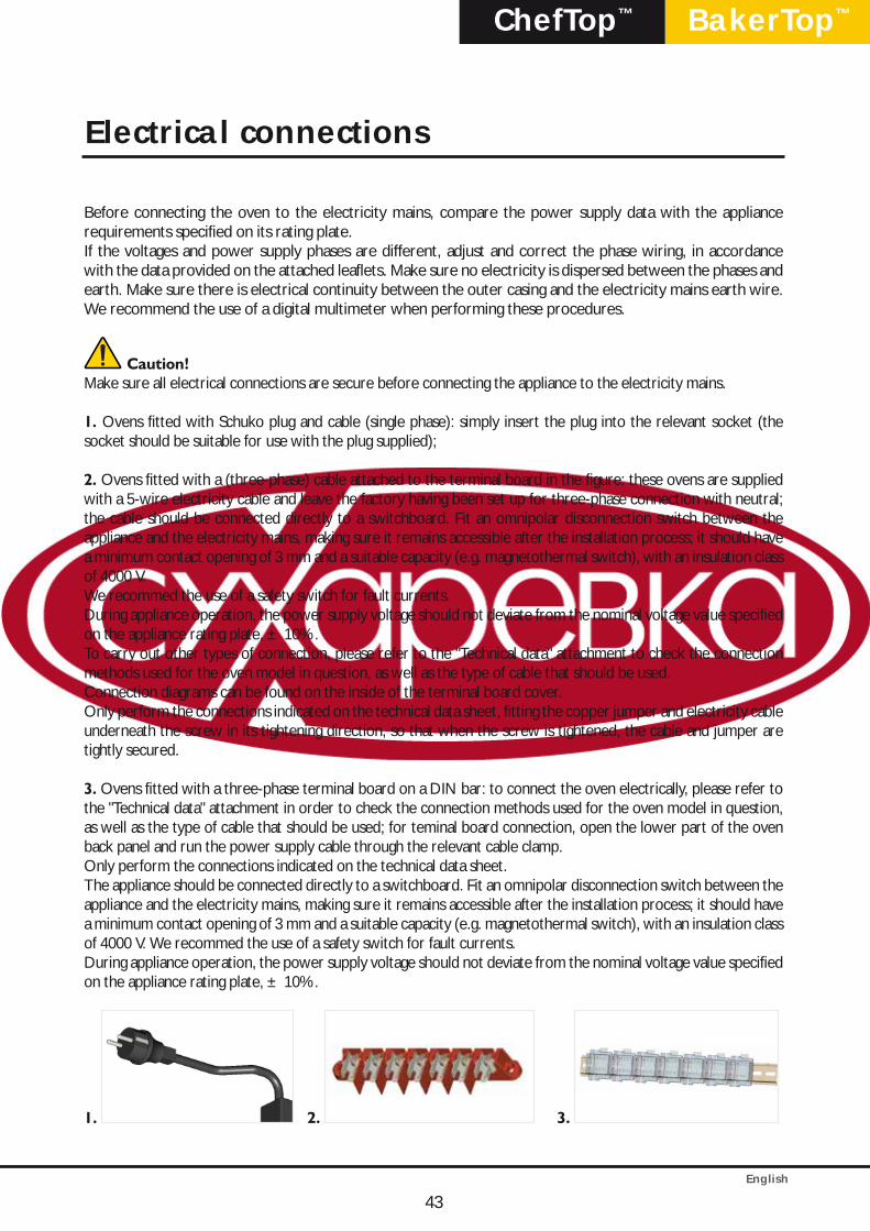
1. Ovens fitted with Schuko plug and cable (single phase): simply insert the plug into the relevant socket (the socket should be suitable for use with the plug supplied);
2. Ovens fitted with a (three-phase) cable attached to the terminal board in the figure: these ovens are supplied with a 5-wire electricity cable and leave the factory having been set up for three-phase connection with neutral; the cable should be connected directly to a switchboard. Fit an omnipolar disconnection switch between the appliance and the electricity mains, making sure it remains accessible after the installation process; it should have a minimum contact opening of 3 mm and a suitable capacity (e.g. magnetothermal switch), with an insulation class of 4000 V.We recommed the use of a safety switch for fault currents.During appliance operation, the power supply voltage should not deviate from the nominal voltage value specified on the appliance rating plate, ± 10%.To carry out other types of connection, please refer to the "Technical data" attachment to check the connection methods used for the oven model in question, as well as the type of cable that should be used.Connection diagrams can be found on the inside of the terminal board cover.Only perform the connections indicated on the technical data sheet, fitting the copper jumper and electricity cable underneath the screw in its tightening direction, so that when the screw is tightened, the cable and jumper are tightly secured.
3. Ovens fitted with a three-phase terminal board on a DIN bar: to connect the oven electrically, please refer to the "Technical data" attachment in order to check the connection methods used for the oven model in question, as well as the type of cable that should be used; for teminal board connection, open the lower part of the oven back panel and run the power supply cable through the relevant cable clamp.Only perform the connections indicated on the technical data sheet.The appliance should be connected directly to a switchboard. Fit an omnipolar disconnection switch between the appliance and the electricity mains, making sure it remains accessible after the installation process; it should have a minimum contact opening of 3 mm and a suitable capacity (e.g. magnetothermal switch), with an insulation class of 4000 V. We recommed the use of a safety switch for fault currents.During appliance operation, the power supply voltage should not deviate from the nominal voltage value specified on the appliance rating plate, ± 10%.
1. 2. 3.
43
Electrical connections
English
44
The cable must only be replaced by authorised personnel. The earthing cable must be yellow and green.To replace the power supply cable (if using a terminal board with a pre-installed cable), proceed as follows:
• Open the terminal board cover by removing the fixing screws• Connect the wires in accordance with the selected connection diagram• Secure the cable using the relevant cable clamp• Close the terminal board cover and tighten the fixing screws
Caution!The power supply cable may only be replaced by the manufacturer, a representative from the Assistance Service or a similarly qualified member of staff.
Incorrect connection may cause the terminal board to overheat so much that it melts.In light of the above information, UNOX accepts no responsibility for any situation resulting from work carried out in an unprofessional manner, or from the incorrect intepretation or application of regulations.The appliance must be connected to the electricity mains earth conductor.
Equipotential connectionThe appliance must be included in an equipotential system, which has been checked for efficiency in accordance with the specifications set out in current regulations.This connection must be performed between different appliances, using the terminal marked as equipotential. The equipotential wire must have a minimum cross-section of 10 mm2 and must be yellow and green.
44
Electrical connections

English
BakerTop™ChefTop™
45
Warning
Caution!Install the appliance in areas with adequate ventilation to prevent the formation of toxic substances. Suffocation hazard!For information relating to ventilation installation and minimum cross-sections, please refer to current installation and safety regulations (and subsequent amendments) for the country in which the oven is installed. Take extra care to ensure that the volume of air required for combustion is not in any way obstructed by objects placed underneath or around the appliance (and especially near the ventilation openings).Always make sure the airflow is sufficient, in order to ensure that combustion takes place properly and that the exchange of air (essential for room hygiene) takes place efficiently.
Caution!Connection to the gas supply, any work required on the gas circuit inside the appliance and all procedures relating to the channelling of exhaust gases must be performed by technicians registered the relevant au-thorities as required by law for the country in which the appliance is installed. These technicians must, nev-ertheless, be aware of and apply the regulations relating to the safety of repaired products and safety in the workplace. In light of the above information, UNOX accepts no responsibility for any situation resulting from work carried out in an unprofessional manner, or from the incorrect intepretation or application of regula-tions or this manual.To ensure that the standard appliance settings correspond to the actual connection conditions, the first time the appliance is operated it will be necessary to perform an analysis of the burner exhaust gases, steam and hot air (CO, CO2), recording the measured values on the appliance.If the undiluted CO value is greater than 1000 ppm, the burner setting should be checked and, if necessary, adjusted by a technician authorised by the company, in accordance with the setting instructions.
Caution!Unsuitable connection may present a fire hazard.Observe the standards established by the local gas authority.Make sure the type of gas available corresponds to the type indicated on the appliance.Do not obstruct or place anything on the combustion gas exhaust located at the top of the appliance.
Caution!Gas connection must only be performed by an authorised installer from the local area.Always make sure the gas connection pipes, and any pipes used in relevant measuring systems, comply with the size indications provided.All parts not supplied by UNOX must be approved in accordance with current regulations.If the pipe pressure differs from the connection flow pressure, contact the local gas authority.If the natural gas connection flow pressure is over 30 mbar, the appliance cannot be operated and the gas part must be shut off.
Caution!The gas system components are designed for a maximum connection flow pressure of 60 mbar. Higher operating pressure values are not permitted.
45
Gas connections
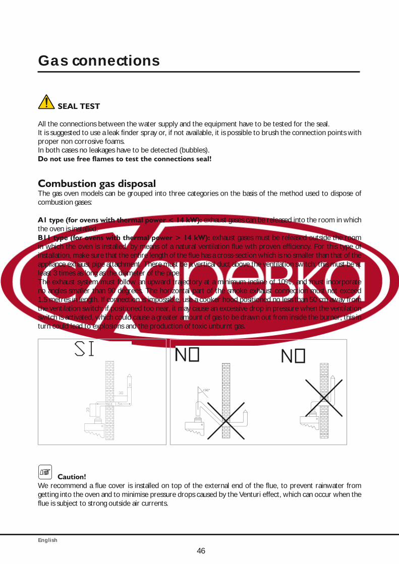
English
SEAL TEST
All the connections between the water supply and the equipment have to be tested for the seal.It is suggested to use a leak finder spray or, if not available, it is possible to brush the connection points with proper non corrosive foams.In both cases no leakages have to be detected (bubbles).Do not use free flames to test the connections seal!
Combustion gas disposalThe gas oven models can be grouped into three categories on the basis of the method used to dispose of combustion gases:
A1 type (for ovens with thermal power < 14 kW): exhaust gases can be released into the room in which the oven is installed.B11 type (for ovens with thermal power > 14 kW): exhaust gases must be released outside the room in which the oven is installed, by means of a natural ventilation flue wth proven efficiency. For this type of installation, make sure that the entire length of the flue has a cross-section which is no smaller than that of the appliance exhaust pipe attachment. There must be a vertical duct above the ventilation switch; this must be at least 3 times as long as the diameter of the pipe.The exhaust system must follow an upward trajectory at a minimum incline of 10%, and must incorporate no angles smaller than 90 degrees. The horizontal part of the smoke exhaust connection must not exceed 1.5 metres in length. If connection is impossible, use a cooker hood positioned no less than 50 cm away from the ventilation switch: if positioned too near, it may cause an excessive drop in pressure when the ventilation switch is activated, which could cause a greater amount of gas to be drawn out from inside the burner; this in turn could lead to explosions and the production of toxic unburnt gas.
Caution!We recommend a flue cover is installed on top of the external end of the flue, to prevent rainwater from getting into the oven and to minimise pressure drops caused by the Venturi effect, which can occur when the flue is subject to strong outside air currents.
46
Gas connections
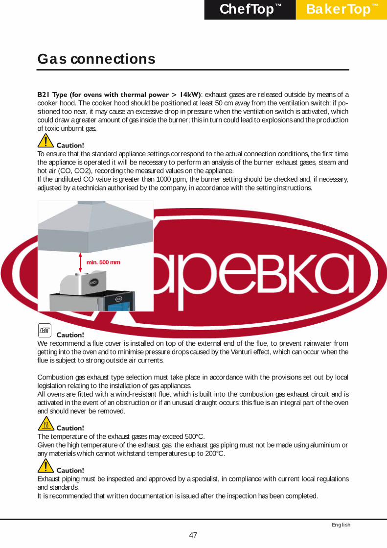
English
BakerTop™ChefTop™
B21 Type (for ovens with thermal power > 14kW): exhaust gases are released outside by means of a cooker hood. The cooker hood should be positioned at least 50 cm away from the ventilation switch: if po-sitioned too near, it may cause an excessive drop in pressure when the ventilation switch is activated, which could draw a greater amount of gas inside the burner; this in turn could lead to explosions and the production of toxic unburnt gas.
Caution!To ensure that the standard appliance settings correspond to the actual connection conditions, the first time the appliance is operated it will be necessary to perform an analysis of the burner exhaust gases, steam and hot air (CO, CO2), recording the measured values on the appliance.If the undiluted CO value is greater than 1000 ppm, the burner setting should be checked and, if necessary, adjusted by a technician authorised by the company, in accordance with the setting instructions.
min. 500 mm
Caution!We recommend a flue cover is installed on top of the external end of the flue, to prevent rainwater from getting into the oven and to minimise pressure drops caused by the Venturi effect, which can occur when the flue is subject to strong outside air currents.
Combustion gas exhaust type selection must take place in accordance with the provisions set out by local legislation relating to the installation of gas appliances.All ovens are fitted with a wind-resistant flue, which is built into the combustion gas exhaust circuit and is activated in the event of an obstruction or if an unusual draught occurs: this flue is an integral part of the oven and should never be removed.
Caution!The temperature of the exhaust gases may exceed 500°C.Given the high temperature of the exhaust gas, the exhaust gas piping must not be made using aluminium or any materials which cannot withstand temperatures up to 200°C.
Caution!Exhaust piping must be inspected and approved by a specialist, in compliance with current local regulations and standards.It is recommended that written documentation is issued after the inspection has been completed.
47
Gas connections
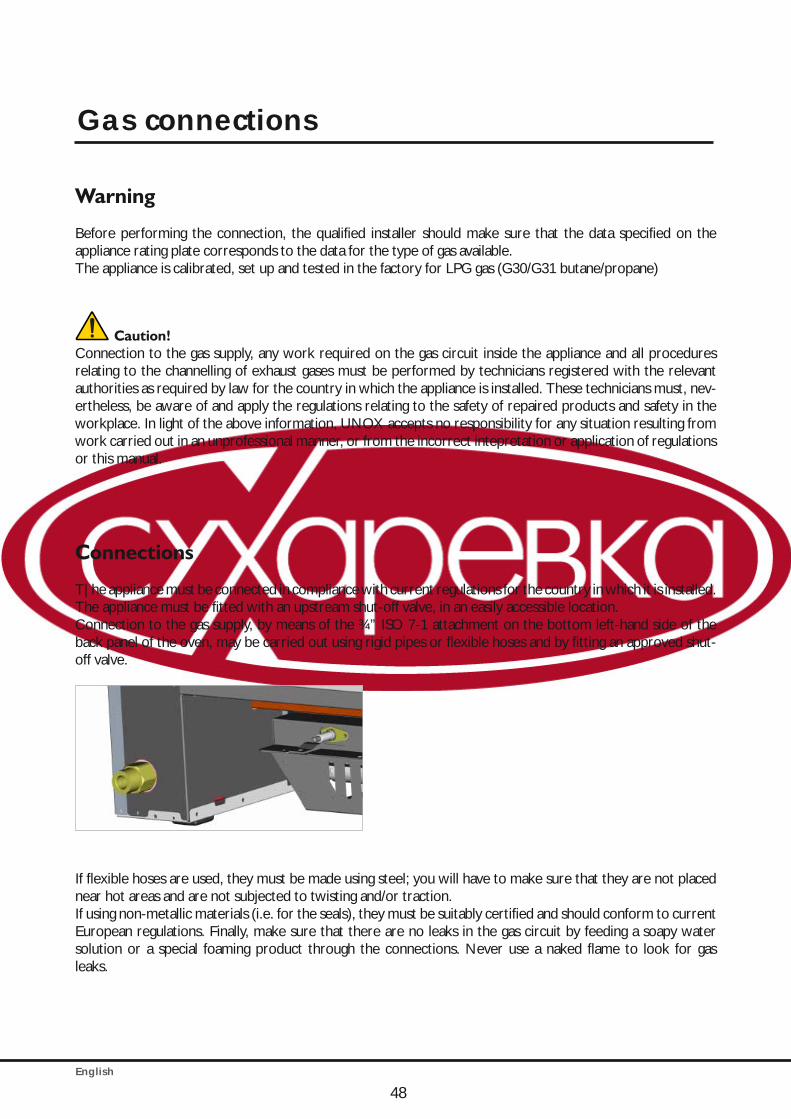
English
Warning
Before performing the connection, the qualified installer should make sure that the data specified on the appliance rating plate corresponds to the data for the type of gas available.The appliance is calibrated, set up and tested in the factory for LPG gas (G30/G31 butane/propane)
Caution!Connection to the gas supply, any work required on the gas circuit inside the appliance and all procedures relating to the channelling of exhaust gases must be performed by technicians registered with the relevant authorities as required by law for the country in which the appliance is installed. These technicians must, nev-ertheless, be aware of and apply the regulations relating to the safety of repaired products and safety in the workplace. In light of the above information, UNOX accepts no responsibility for any situation resulting from work carried out in an unprofessional manner, or from the incorrect intepretation or application of regulations or this manual.
Connections
T|he appliance must be connected in compliance with current regulations for the country in which it is installed. The appliance must be fitted with an upstream shut-off valve, in an easily accessible location.Connection to the gas supply, by means of the ¾” ISO 7-1 attachment on the bottom left-hand side of the back panel of the oven, may be carried out using rigid pipes or flexible hoses and by fitting an approved shut-off valve.
If flexible hoses are used, they must be made using steel; you will have to make sure that they are not placed near hot areas and are not subjected to twisting and/or traction.If using non-metallic materials (i.e. for the seals), they must be suitably certified and should conform to current European regulations. Finally, make sure that there are no leaks in the gas circuit by feeding a soapy water solution or a special foaming product through the connections. Never use a naked flame to look for gas leaks.
48
Gas connections

English
BakerTop™ChefTop™
Gas SetupThe gas type in the gas pipe network must be checked by a qualified technician that, if necessary, replaces the nozzle, adjusts the primary air and sets the type of gas on the oven control panel and apply the label.
Nozzle replacement and primary air adjustment Using the table in the attached technical data sheet, replace the main injector and adjust the primary air using the corresponding bushing. This procedure should only be carried out once the gas valve upstream of the oven has been shut off and the power supply disconnected. Make sure that the diameter measurement of the injector to be replaced is stamped on it, in hundredths of a millimetre (1/100 mm). The injector is located at the rear, on the bottom left-hand side. To replace the injector and adjust the primary air, proceed as follows(see illustration below):
• Loosen screw A.• Adjust bushing B in accordance with the information provided in the attached table.• Unscrew and remove injector C using a 13 mm spanner.• Install the injector most suited to the type of gas supplied (see relevant technical table).• Position bushing B at the correct distance H (see relevant technical table).• Re-tighten screw A.
There are 2 types of nozzle:- one suitable for G20 and G25 gas- one suitable for G30 (G31) gas
OVEN GAS NOZZLE CODENOZZLE DIAMETER
[1/100 mm]PRIMARY AIR
L [mm]INSTALLATION
XBC 615 GG20,G25 BR1275A0 345 All open
L=39 mmIn the appliance
G30,G31 BR1055A0 225 Installed
XBC 815 GG20,G25 UG1001A0 375 All open
L=39 mmIn the appliance
G30,G31 BR1250A0 245 Installed
XVC 315 GG20,G25 BR1020A0 280 All open
L=39 mmIn the appliance
G30,G31 BR1085A0 185 Installed
XVC 515 GG20,G25 BR1270A0 335 All open
L=39 mmIn the appliance
G30,G31 BR1150A0 220 Installed
XVC 715 GG20,G25 BR1280A0 365 All open
L=39 mm
In the appliance
G30,G31 BR1180A0 235 Installed
XVC 1215 GG20,G25 BR1275A0 345 All open
L=39 mmIn the appliance
G30,G31 BR1055A0 225 Installed
XVC 2015 GG20,G25 UG1001A0 375 All open
L=39 mmIn the appliance
G30,G31 BR1250A0 245 Installed
XVC915G - XVC1015G XBC915G - XBC1015G
G20,G25 BR1245A0 355All open
L=39 mmIn the appliance
G30,G31 BR1055A0 225 L=16 mm Installed
XVC3215G - XVC4015GG20,G25 BR1245A0 355
All openL=39 mm
In the appliance
G30,G31 BR1055A0 225 L=16 mm Installed
Gas connections
49
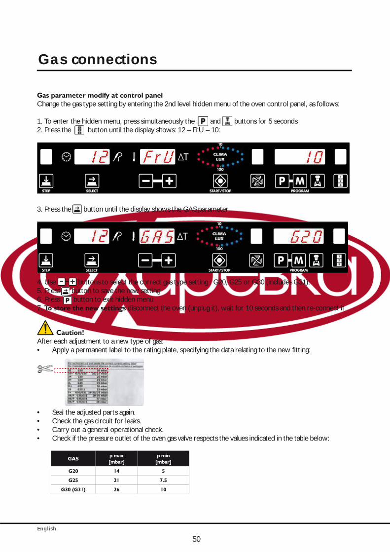
English
50
Gas parameter modify at control panelChange the gas type setting by entering the 2nd level hidden menu of the oven control panel, as follows:
1. To enter the hidden menu, press simultaneously the and buttons for 5 seconds2. Press the button until the display shows: 12 – FrU – 10:
3. Press the button until the display shows the GAS parameter
4. Use - +- buttons to select the correct gas type setting : G20, G25 or G30 (includes G31).5. Press button to save the new setting 6. Press button to exit hidden menu7. To store the new settings disconnect the oven (unplug it), wait for 10 seconds and then re-connect it
Caution!After each adjustment to a new type of gas:• Apply a permanent label to the rating plate, specifying the data relating to the new fitting:
• Seal the adjusted parts again.• Check the gas circuit for leaks.• Carry out a general operational check.• Check if the pressure outlet of the oven gas valve respects the values indicated in the table below:
GASp max [mbar]
p min [mbar]
G20 14 5
G25 21 7.5
G30 (G31) 26 10
Gas connections
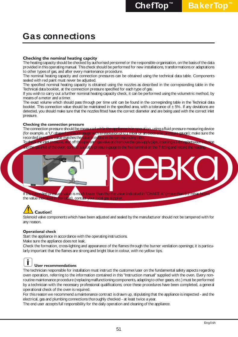
English
BakerTop™ChefTop™
51
Checking the nominal heating capcityThe heating capacity should be checked by authorised personnel or the responsible organisation, on the basis of the data provided in this operating manual. This check should be performed for new installations, transformations or adaptations to other types of gas, and after every maintenance procedure.The nominal heating capacity and connection pressures can be obtained using the technical data table. Components sealed with red paint must never be adjusted.The specified nominal heating capacity is obtained using the nozzles as described in the correpsonding table in the Technical data booklet, at the connection pressure specified for each type of gas.If you wish to carry out a further nominal heating capacity check, it can be performed using the volumetric method, by means of a meter and a timer.The exact volume which should pass through per time unit can be found in the correspinding table in the Technical data booklet. This connection value should be maintained in the specified area, with a tolerance of ±5%. If any deviations are detected, you should make sure that the nozzles fitted have the correct diameter and are being used with the correct inlet pressure.
Checking the connection pressure The connection pressure should be measured while the appliance is in operation, using a fluid pressure measuring device (for example, a "U"-shaped pressure gauge with a resolution of 0.1 mbar or an electronic pressure gauge); make sure the recorded pressure value matches the value provided in the corresponding table. To check the inlet pressure, shut off the upstream gas valve and remove the gas supply pipe, inserting a T-fitting between this pipe and the gas inlet of the oven; connect a suitable pressure gauge to the free terminal on the T-fitting and record the reading.
If the recorded pressure value is much lower than the the value indicated in "CHART A" (more than 0.2 mbar below the value indicated in the table), contact your local gas supplier.
Caution!Solenoid valve components which have been adjusted and sealed by the manufacturer should not be tampered with for any reason.
Operational check Start the appliance in accordance with the operating instructions.Make sure the appliance does not leak.Check the formation, cross-lighting and appearance of the flames through the burner venilation openings; it is particu-larly important that the flames are strong and bright blue in colour, with no yellow tips.
User recommendationsThe technician responsible for installation must instruct the customer/user on the fundamental safety aspects regarding oven operation, referring to the information contained in this "Instruction manual" supplied with the oven. Every non-routine maintenance procedure (replacing malfunctioning components, adapting to other gases, etc.) must be performed by a technician with the necessary professional qualifications; once these procedures have been completed, a general operational check of the oven is required.For this reason we recommend a maintenance contract is drawn up, stipulating that the appliance is inspected - and the electrical, gas and plumbing connections thoroughly checked - at least twice a year.The end user accepts full responsibility for the daily operation and cleaning of the appliance.
Gas connections
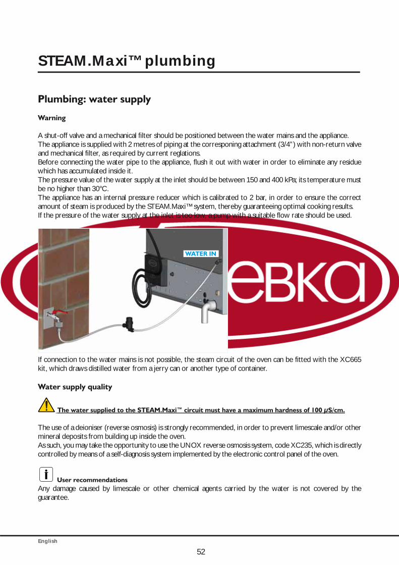
English
52
Plumbing: water supply
Warning
A shut-off valve and a mechanical filter should be positioned between the water mains and the appliance.The appliance is supplied with 2 metres of piping at the corresponing attachment (3/4”) with non-return valve and mechanical filter, as required by current reglations.Before connecting the water pipe to the appliance, flush it out with water in order to eliminate any residue which has accumulated inside it.The pressure value of the water supply at the inlet should be between 150 and 400 kPa; its temperature must be no higher than 30°C.The appliance has an internal pressure reducer which is calibrated to 2 bar, in order to ensure the correct amount of steam is produced by the STEAM.Maxi™ system, thereby guaranteeing optimal cooking results.If the pressure of the water supply at the inlet is too low, a pump with a suitable flow rate should be used.
WATER IN
If connection to the water mains is not possible, the steam circuit of the oven can be fitted with the XC665 kit, which draws distilled water from a jerry can or another type of container.
Water supply quality
The water supplied to the STEAM.Maxi™ circuit must have a maximum hardness of 100 μS/cm.
The use of a deioniser (reverse osmosis) is strongly recommended, in order to prevent limescale and/or other mineral deposits from building up inside the oven.As such, you may take the opportunity to use the UNOX reverse osmosis system, code XC235, which is directly controlled by means of a self-diagnosis system implemented by the electronic control panel of the oven.
User recommendationsAny damage caused by limescale or other chemical agents carried by the water is not covered by the guarantee.
STEAM.Maxi™ plumbing
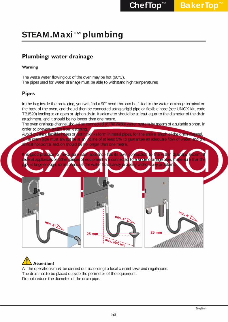
English
BakerTop™ChefTop™
53
Plumbing: water drainage
Warning
The waste water flowing out of the oven may be hot (90°C).The pipes used for water drainage must be able to withstand high temperatures.
Pipes
In the bag inside the packaging, you will find a 90° bend that can be fitted to the water drainage terminal on the back of the oven, and should then be connected using a rigid pipe or flexible hose (see UNOX kit, code TB1520) leading to an open or siphon drain. Its diameter should be at least equal to the diameter of the drain attachment, and it should be no longer than one metre. The oven drainage channel should be connected to the waste water system by means of a suitable siphon, in order to prevent steam from escaping.Avoid crushing flexible hoses or letting kinks form in metal pipes, for the entire length of the drain channel. T|he drain pipe must always be at an incline of at least 5% to guarantee an adequate flow of water, and the almost horizontal section should be no longer than one metre.
It is good practice to make sure each appliance has its own connection to the water drainage system. If several appliances or other pieces of equipment are connected to a single drainage pipe, make sure that the pipe is large enough, so as to ensure the water flows away properly without any problems.
min. 4°
25 mmmax. 2000 mm
min. 4°
min. 4°
25 mm
Attention!All the operations must be carried out according to local current laws and regulations.The drain has to be placed outside the perimeter of the equipment.Do not reduce the diameter of the drain pipe.
STEAM.Maxi™ plumbing
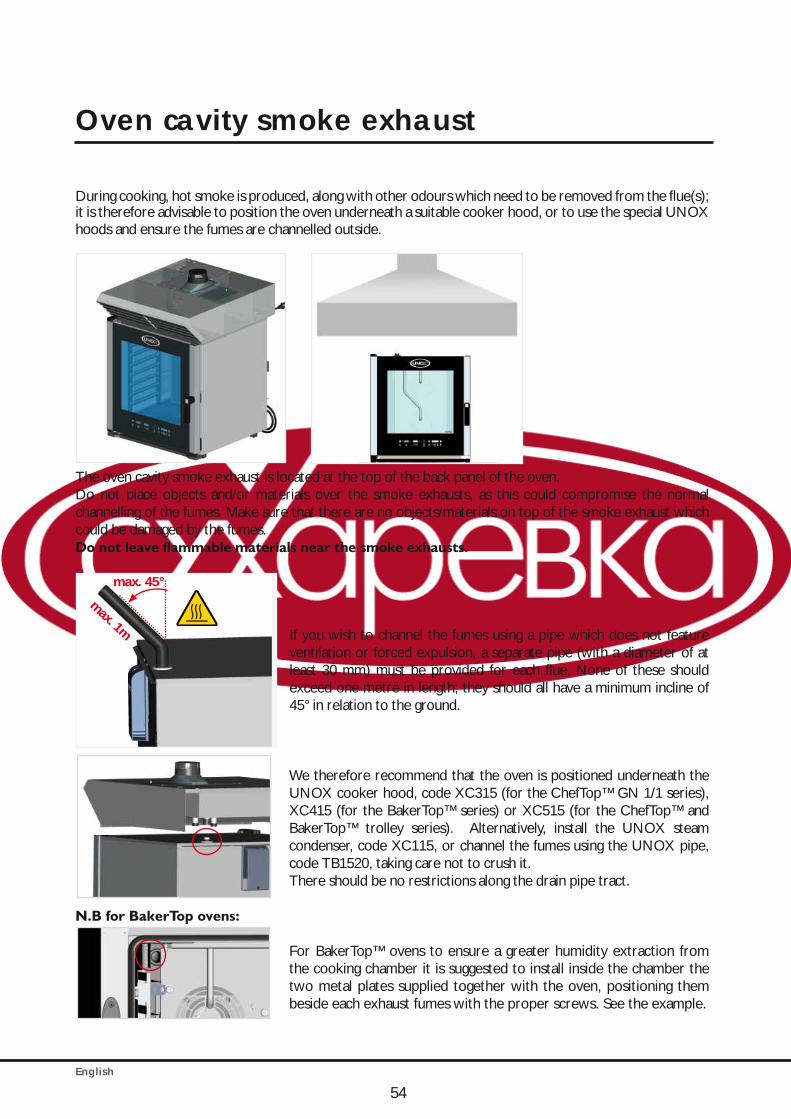
English
During cooking, hot smoke is produced, along with other odours which need to be removed from the flue(s); it is therefore advisable to position the oven underneath a suitable cooker hood, or to use the special UNOX hoods and ensure the fumes are channelled outside.
The oven cavity smoke exhaust is located at the top of the back panel of the oven.Do not place objects and/or materials over the smoke exhausts, as this could compromise the normal channelling of the fumes. Make sure that there are no objects/materials on top of the smoke exhaust which could be damaged by the fumes.Do not leave flammable materials near the smoke exhausts.
If you wish to channel the fumes using a pipe which does not feature ventilation or forced expulsion, a separate pipe (with a diameter of at least 30 mm) must be provided for each flue. None of these should exceed one metre in length; they should all have a minimum incline of 45° in relation to the ground.
We therefore recommend that the oven is positioned underneath the UNOX cooker hood, code XC315 (for the ChefTop™ GN 1/1 series), XC415 (for the BakerTop™ series) or XC515 (for the ChefTop™ and BakerTop™ trolley series). Alternatively, install the UNOX steam condenser, code XC115, or channel the fumes using the UNOX pipe, code TB1520, taking care not to crush it.There should be no restrictions along the drain pipe tract.
N.B for BakerTop ovens:
For BakerTop™ ovens to ensure a greater humidity extraction from the cooking chamber it is suggested to install inside the chamber the two metal plates supplied together with the oven, positioning them beside each exhaust fumes with the proper screws. See the example.
54
Oven cavity smoke exhaust
max. 1m
max. 45°
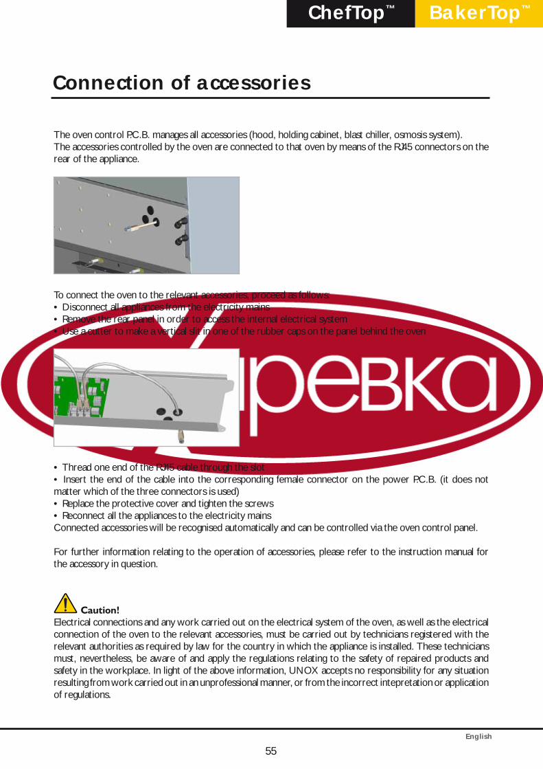
English
BakerTop™ChefTop™
The oven control P.C.B. manages all accessories (hood, holding cabinet, blast chiller, osmosis system).The accessories controlled by the oven are connected to that oven by means of the RJ45 connectors on the rear of the appliance.
To connect the oven to the relevant accessories, proceed as follows:• Disconnect all appliances from the electricity mains• Remove the rear panel in order to access the internal electrical system• Use a cutter to make a vertical slit in one of the rubber caps on the panel behind the oven
• Thread one end of the RJ45 cable through the slot• Insert the end of the cable into the corresponding female connector on the power P.C.B. (it does not matter which of the three connectors is used)• Replace the protective cover and tighten the screws• Reconnect all the appliances to the electricity mainsConnected accessories will be recognised automatically and can be controlled via the oven control panel.
For further information relating to the operation of accessories, please refer to the instruction manual for the accessory in question.
Caution!Electrical connections and any work carried out on the electrical system of the oven, as well as the electrical connection of the oven to the relevant accessories, must be carried out by technicians registered with the relevant authorities as required by law for the country in which the appliance is installed. These technicians must, nevertheless, be aware of and apply the regulations relating to the safety of repaired products and safety in the workplace. In light of the above information, UNOX accepts no responsibility for any situation resulting from work carried out in an unprofessional manner, or from the incorrect intepretation or application of regulations.
55
Connection of accessories
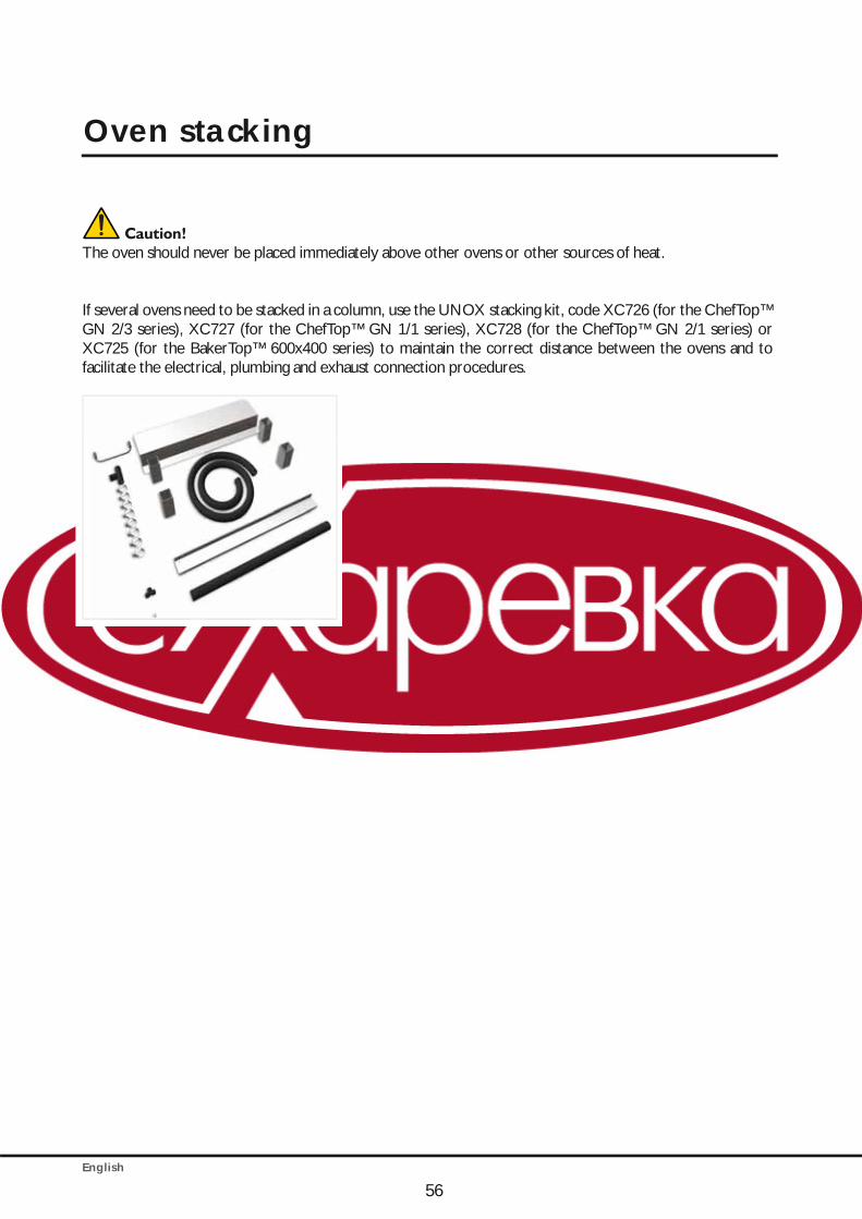
English
Caution!The oven should never be placed immediately above other ovens or other sources of heat.
If several ovens need to be stacked in a column, use the UNOX stacking kit, code XC726 (for the ChefTop™ GN 2/3 series), XC727 (for the ChefTop™ GN 1/1 series), XC728 (for the ChefTop™ GN 2/1 series) or XC725 (for the BakerTop™ 600x400 series) to maintain the correct distance between the ovens and to facilitate the electrical, plumbing and exhaust connection procedures.
Oven stacking
56
English
BakerTop™ChefTop™
Certification
Manufacturer: UNOX S.p.A.Address: Via Dell’Artigianato, 28/30 - I - 35010 - Vigodarzere, Padua, Italy Product: Combined oven for professional use Family: ChefTop™ – BakerTop™
REFERENCE STANDARDSThe "CE" mark on the appliances named in this manual refers to the following directives:
Low Voltage directive 2006/95/EC, in accordance with standards:EN 60335-2-42:2003 + A1:2008 used in conjunction with EN 60335-1:2002 + A11:2004 + A1:2004 + A12:2006 + A2:2006 + A13:2008EN 62233:2008
Electromagnetic Compatibility directive 2004/108/EC, in accordance with standards: EN 55014-1:2006EN 55014-2:1997 + A1:2001EN 61000-3-2:2006EN 61000-3-3:1995 + A1:2001 + A2:2005EN 61000-3-11:2000
Gas Appliances Directive 90/396/CEE, following the rules and current updating:EN203-1EN203-2-2EN347
57

LI21
45A
1 -
Stam
pato
: 05-
2010
OVENS PLANET®
www.unox.com