Embed Size (px)
Citation preview
Unmet Load Hours Troubleshooting Guide
IES Virtual Environment 2013 Feature Pack 1
How to use this Document This guide is designed to help reduce or eliminate unmet load hours in a model. You should begin by
understanding what an unmet load hour is, using the “Definition” section of this document. Next, you should
identify when and where unmet load hours occur in your model. The “Unmet Load Hours Tests” section in
this document will walk you through that process.
To determine the cause of unmet load hours in your model, follow the methodology in the “Common Causes of
Unmet Load Hours” section. You can effectively interrogate the results of your building simulation by working
through each subsection, or you may use the links in the Contents below to skip to a particular section for
reference.
As you troubleshoot your model, you may find it useful to adjust the parameters of your dynamic simulation.
The “Simulation Settings” section of this document will guide you through adjustments that may make your
results easier to interrogate.
Contents
1.0 Definition .......................................................................................................................................... 3
2.0 Unmet Load Hours Tests .................................................................................................................... 4
2.1 Definitions of Terms used in the Unmet Load Hours Range Tests ....................................................... 5
3.0 Common Causes of Unmet Load Hours .............................................................................................. 6
3.1 Setpoints & Profiles .................................................................................................................................. 6
3.2 Controllers ................................................................................................................................................ 9
3.2.1 Flow ...................................................................................................................................................... 9
3.2.2 Temperature ....................................................................................................................................... 11
3.3 Undersizing ............................................................................................................................................. 14
3.3.1 Weather Data ..................................................................................................................................... 14
3.3.2 Sizing vs. Simulation ........................................................................................................................... 15
3.3.3 Enter Air Temperature ........................................................................................................................ 16
3.3.4 Plant Sizing .......................................................................................................................................... 17
4.0 Simulation Settings ......................................................................................................................... 18
4.1 Output Options ....................................................................................................................................... 18
4.2 Time Steps and Intervals ........................................................................................................................ 20
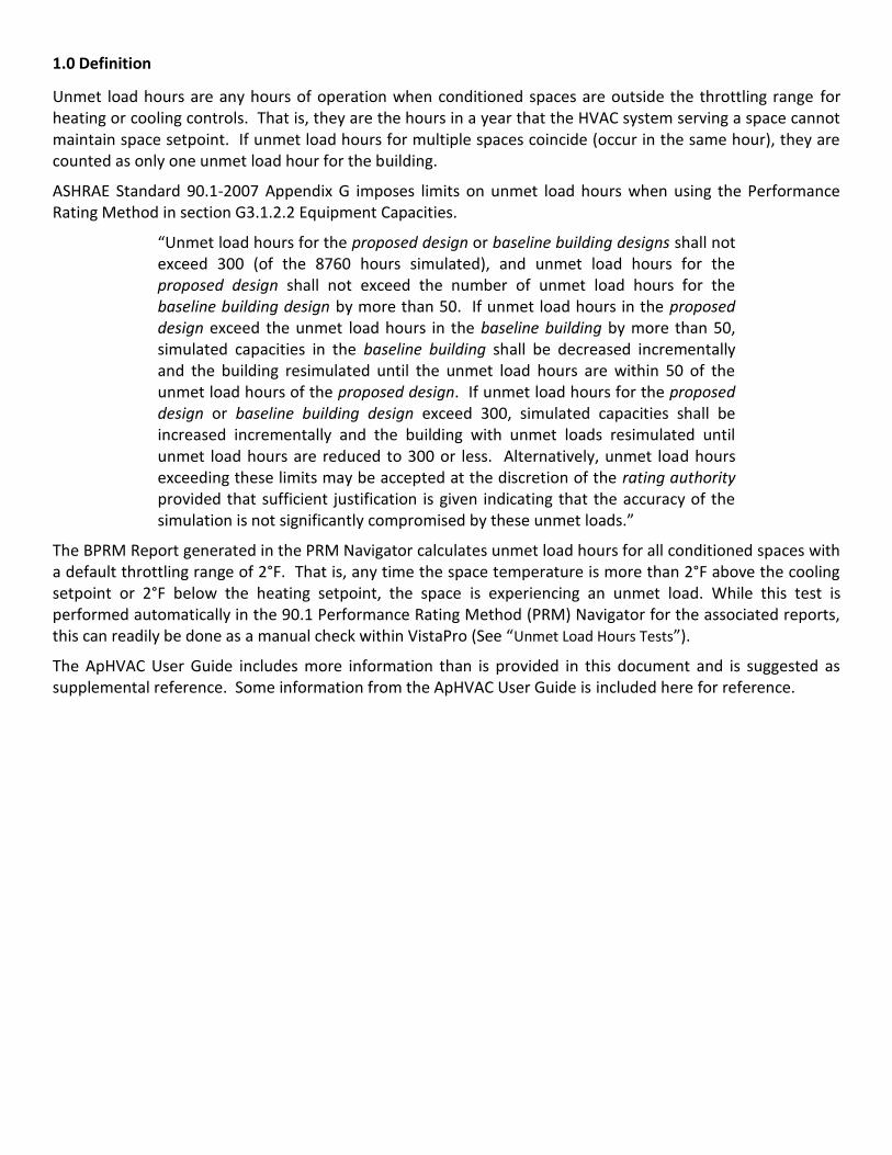
1.0 Definition
Unmet load hours are any hours of operation when conditioned spaces are outside the throttling range for heating or cooling controls. That is, they are the hours in a year that the HVAC system serving a space cannot maintain space setpoint. If unmet load hours for multiple spaces coincide (occur in the same hour), they are counted as only one unmet load hour for the building.
ASHRAE Standard 90.1-2007 Appendix G imposes limits on unmet load hours when using the Performance Rating Method in section G3.1.2.2 Equipment Capacities.
“Unmet load hours for the proposed design or baseline building designs shall not exceed 300 (of the 8760 hours simulated), and unmet load hours for the proposed design shall not exceed the number of unmet load hours for the baseline building design by more than 50. If unmet load hours in the proposed design exceed the unmet load hours in the baseline building by more than 50, simulated capacities in the baseline building shall be decreased incrementally and the building resimulated until the unmet load hours are within 50 of the unmet load hours of the proposed design. If unmet load hours for the proposed design or baseline building design exceed 300, simulated capacities shall be increased incrementally and the building with unmet loads resimulated until unmet load hours are reduced to 300 or less. Alternatively, unmet load hours exceeding these limits may be accepted at the discretion of the rating authority provided that sufficient justification is given indicating that the accuracy of the simulation is not significantly compromised by these unmet loads.”
The BPRM Report generated in the PRM Navigator calculates unmet load hours for all conditioned spaces with a default throttling range of 2°F. That is, any time the space temperature is more than 2°F above the cooling setpoint or 2°F below the heating setpoint, the space is experiencing an unmet load. While this test is performed automatically in the 90.1 Performance Rating Method (PRM) Navigator for the associated reports, this can readily be done as a manual check within VistaPro (See “Unmet Load Hours Tests”).
The ApHVAC User Guide includes more information than is provided in this document and is suggested as supplemental reference. Some information from the ApHVAC User Guide is included here for reference.

2.0 Unmet Load Hours Tests
After you have run a dynamic simulation, go into VistaPro to perform a range test on all of the conditioned spaces in your model with the following settings to identify where the unmet heating & cooling hours occur:
Figure 2.0-1: Range Test for Unmet Load Hours
To determine when unmet hours are occurring for each space, compare the room air temperature with the space setpoint:
Figure 2.0-2: Annual Air Temperature & Cooling Setpoint

2.1 Definitions of Terms used in the Unmet Load Hours Range Tests
The terminology used in the range test tools for unmet load hours is somewhat specialized. The following definitions may be helpful in using the Range Test dialog for unmet load hour tests:
When Occupied: All times for any particular room when occupancy is greater than zero.
When room heated or cooled: Tests for hours out of range relative to the setpoint profiles at all times for each particular room, so long as the value for the on/off profile for either heating or cooling = on. If there are warm-up and after-hours operating periods over which the daytime setpoints are extended, this test will use daytime setpoints during these time periods. This test does not allow for room temperature transition from setback to setpoint.
When plant profile on full: All times for a particular room during which the normal daytime setpoint should be fully met—i.e., fully excluding unoccupied/nighttime operation (outside of “opening hours”) and both morning start-up and after-hours operation.
When conditioned (incl. setback): Tests for hours out of range relative to setpoints, applying the unoccupied/nighttime setback values to any morning start-up and after-hours operating periods during all times for a particular room when the on/off heating or cooling profile = ON. This test assumes, for example, that the full morning warm-up period will be needed to raise a particular zone from the setback temperature to the daytime setpoint, and therefore does allow for room temperature transition from setback to setpoint.
Between room setpoints (+/- differential tolerances): Test to count hours in three categories:
o Below the heating setpoint minus the heating control band tolerances
o Between room setpoints, +/- the set control band tolerances
o Above the cooling setpoint plus the heating control band tolerances
Test temperatures in controlled band, tolerances in °F: These values set the added tolerance above and below the setpoints that should be applied to determine when a temperature is “out of range.” The tolerances allow for the throttling or control of HVAC parameters such as variable water and air flow rates in coils and ducts to address loads. The pre-defined systems all reference profiles that have names beginning with “HVAC,” and so long as they are changed only via the System Schedules dialog, these profiles are maintained with standard throttling ranges relative to the heating and cooling setpoints. Unless you’ve set up your own HVAC controller profiles or have revised values in the pre-defined “HVAC” profiles within ApPro, the
standard 2F for both heating and cooling when working in IP units (1.11C when in metric) should be used here. If you have set up custom control profiles, you will need to set these tolerance values to allow for the throttling range in the custom profiles.
Averaged, shared hours (for ‘unmet hours’ test): This looks at average temperature over the full one-hour period in each room for each hour and then adds any particular out-of-range hour to the total “shared hours” tally only once, regardless of how many rooms or zones were out of range during that hour. The “shared hours” total of each column is displayed in the bottom row of the table.
With all conditioned spaces selected, the total of shared hours reported in the bottom row as outside the control ranges for both heating and cooling are collectively the Unmet Load Hours.
A space temperature is considered out of range (under-heated or under-cooled) for any hour when the average temperature for that hour is below the heating setpoint less the control band tolerance or above the cooling setpoint plus the control band tolerance. The “shared hours” might be thought of as a logical ‘OR’ test, with each hour counted only once when any one or more rooms in the currently selected set of rooms is/are out of range.

3.0 Common Causes of Unmet Load Hours
3.1 Setpoints & Profiles
One common cause of unmet load hours is having an incorrect setpoint. If you notice that the setpoint your room air temperature is compared against for the unmet hours test is correct, adjust the profile selected in the building template manager.
Figure 3.1-1: Heating & Cooling Setpoints in the Building Template Manager
Figure 3.1-2: SYS_Heating Setpoint and SYS_Cooling Setpoint Profiles
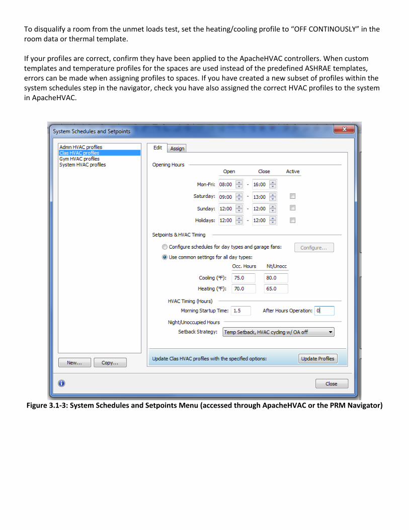
To disqualify a room from the unmet loads test, set the heating/cooling profile to “OFF CONTINOUSLY” in the room data or thermal template. If your profiles are correct, confirm they have been applied to the ApacheHVAC controllers. When custom templates and temperature profiles for the spaces are used instead of the predefined ASHRAE templates, errors can be made when assigning profiles to spaces. If you have created a new subset of profiles within the system schedules step in the navigator, check you have also assigned the correct HVAC profiles to the system in ApacheHVAC.
Figure 3.1-3: System Schedules and Setpoints Menu (accessed through ApacheHVAC or the PRM Navigator)
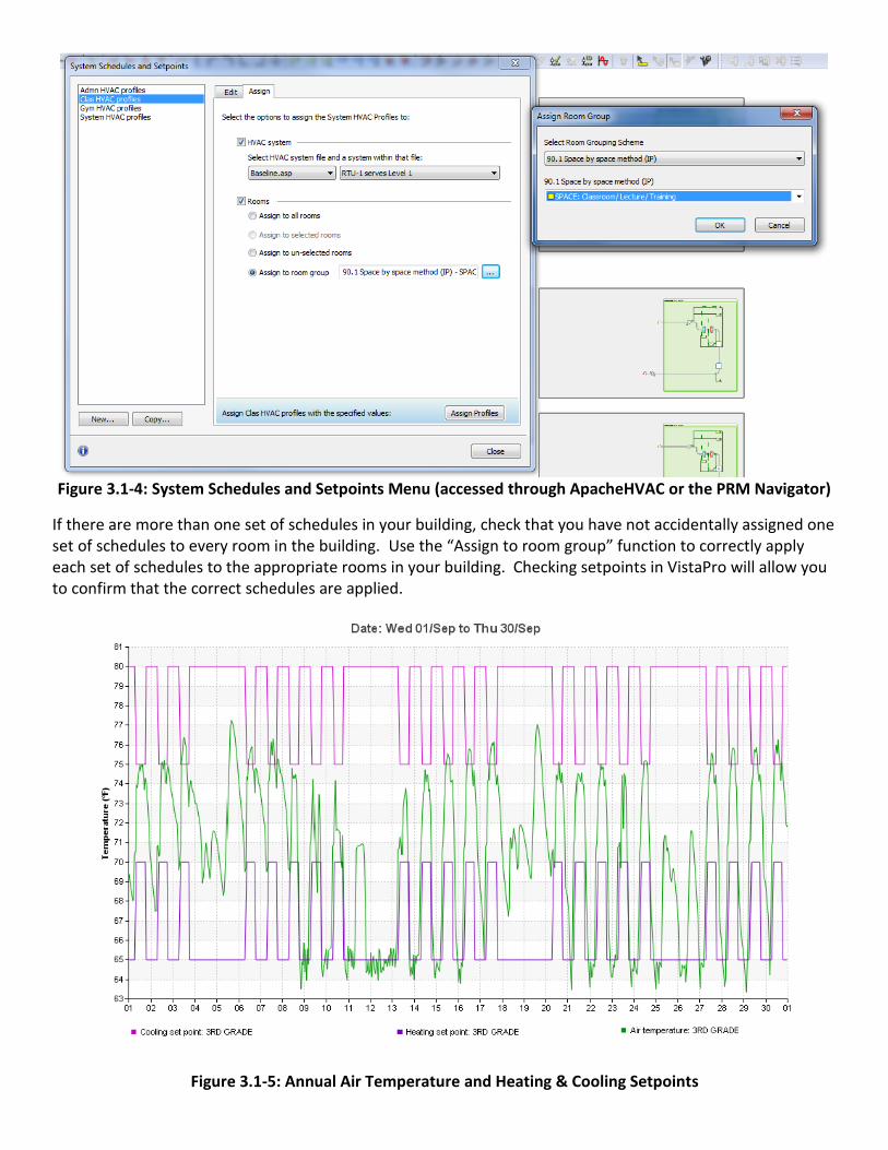
Figure 3.1-4: System Schedules and Setpoints Menu (accessed through ApacheHVAC or the PRM Navigator)
If there are more than one set of schedules in your building, check that you have not accidentally assigned one set of schedules to every room in the building. Use the “Assign to room group” function to correctly apply each set of schedules to the appropriate rooms in your building. Checking setpoints in VistaPro will allow you to confirm that the correct schedules are applied.
Figure 3.1-5: Annual Air Temperature and Heating & Cooling Setpoints
3.2 Controllers
If the profiles & templates are okay, begin examining what is happening in your system & space by looking at the ApacheHVAC network in VistaPro.
3.2.1 Flow
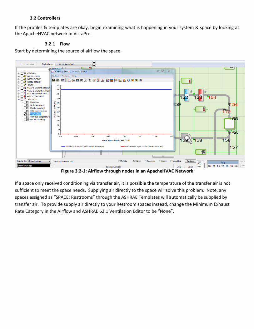
Start by determining the source of airflow the space.
Figure 3.2-1: Airflow through nodes in an ApacheHVAC Network
If a space only received conditioning via transfer air, it is possible the temperature of the transfer air is not
sufficient to meet the space needs. Supplying air directly to the space will solve this problem. Note, any
spaces assigned as “SPACE: Restrooms” through the ASHRAE Templates will automatically be supplied by
transfer air. To provide supply air directly to your Restroom spaces instead, change the Minimum Exhaust
Rate Category in the Airflow and ASHRAE 62.1 Ventilation Editor to be “None”.

Figure 3.2-2: ASHRAE 62.1 Ventilation Editor
As an alternative to supplying air directly to spaces in baseline buildings, the set point can be changed. This method may be preferred in PRM projects if transfer air sufficiently conditions the same spaces in the proposed building as it will not increase the energy used in the baseline building. Changing the set points in the building template manager will not affect the setpoints assigned in Apache HVAC systems and will not require room or system load calculations to be repeated.
Check to see if the space is receiving the proper amount of airflow. A room experiencing unmet load hours should be receiving the maximum designed airflow during those hours.
Figure 3.2-3: Airflow into a Space
If it’s not, check the values in the controllers that specify flow and confirm that they are correct. In variable volume systems, the flow may modulate based on sensed variables. You can check those variables in VistaPro and work backwards to understand the system operation.
3.2.2 Temperature
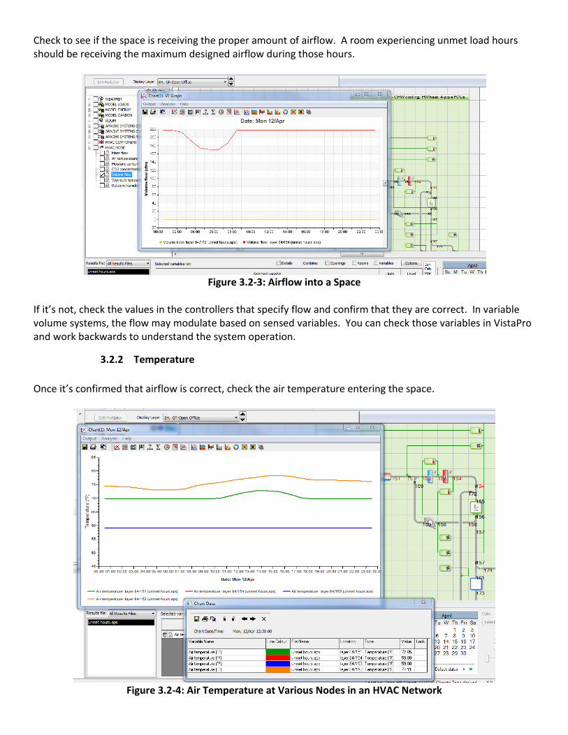
Once it’s confirmed that airflow is correct, check the air temperature entering the space.
Figure 3.2-4: Air Temperature at Various Nodes in an HVAC Network
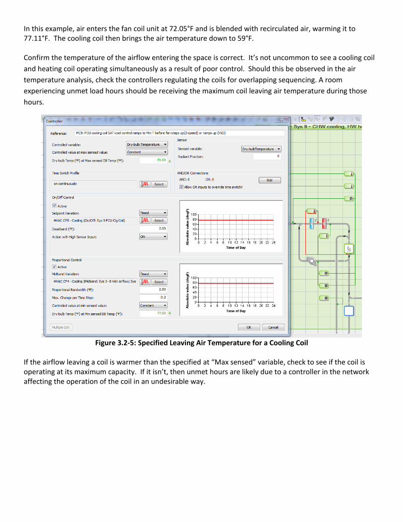
In this example, air enters the fan coil unit at 72.05°F and is blended with recirculated air, warming it to 77.11°F. The cooling coil then brings the air temperature down to 59°F.
Confirm the temperature of the airflow entering the space is correct. It’s not uncommon to see a cooling coil
and heating coil operating simultaneously as a result of poor control. Should this be observed in the air
temperature analysis, check the controllers regulating the coils for overlapping sequencing. A room
experiencing unmet load hours should be receiving the maximum coil leaving air temperature during those
hours.
Figure 3.2-5: Specified Leaving Air Temperature for a Cooling Coil
If the airflow leaving a coil is warmer than the specified at “Max sensed” variable, check to see if the coil is operating at its maximum capacity. If it isn’t, then unmet hours are likely due to a controller in the network affecting the operation of the coil in an undesirable way.

Figure 3.2-6: Cooling Coil Data
Figure 3.2-7: Cooling Coil Operation during Unmet Load Hour

3.3 Undersizing
A coil operating at its maximum capacity and not achieving the proper leaving air temperature is undersized. There are several factors that can cause the coil to be undersized during the autosizing process:
3.3.1 Weather Data
Different weather data is used for the autosizing process than is used for the dynamic simulation. Confirm the correct weather data for the project location is being used in both processes in the Apache weather/location database manager.
Figure 3.3-1: Weather Data use for Autosizing
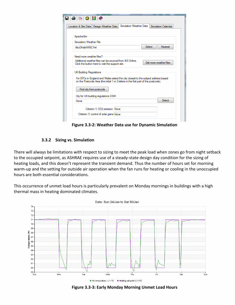
Figure 3.3-2: Weather Data use for Dynamic Simulation
3.3.2 Sizing vs. Simulation
There will always be limitations with respect to sizing to meet the peak load when zones go from night setback to the occupied setpoint, as ASHRAE requires use of a steady-state design day condition for the sizing of heating loads, and this doesn’t represent the transient demand. Thus the number of hours set for morning warm-up and the setting for outside air operation when the fan runs for heating or cooling in the unoccupied hours are both essential considerations. This occurrence of unmet load hours is particularly prevalent on Monday mornings in buildings with a high thermal mass in heating dominated climates.
Figure 3.3-3: Early Monday Morning Unmet Load Hours
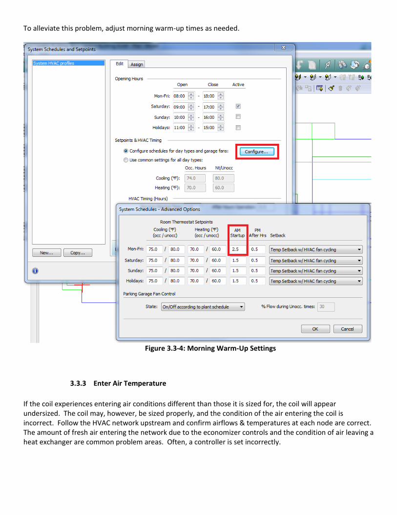
To alleviate this problem, adjust morning warm-up times as needed.
Figure 3.3-4: Morning Warm-Up Settings
3.3.3 Enter Air Temperature
If the coil experiences entering air conditions different than those it is sized for, the coil will appear undersized. The coil may, however, be sized properly, and the condition of the air entering the coil is incorrect. Follow the HVAC network upstream and confirm airflows & temperatures at each node are correct. The amount of fresh air entering the network due to the economizer controls and the condition of air leaving a heat exchanger are common problem areas. Often, a controller is set incorrectly.
3.3.4 Plant Sizing
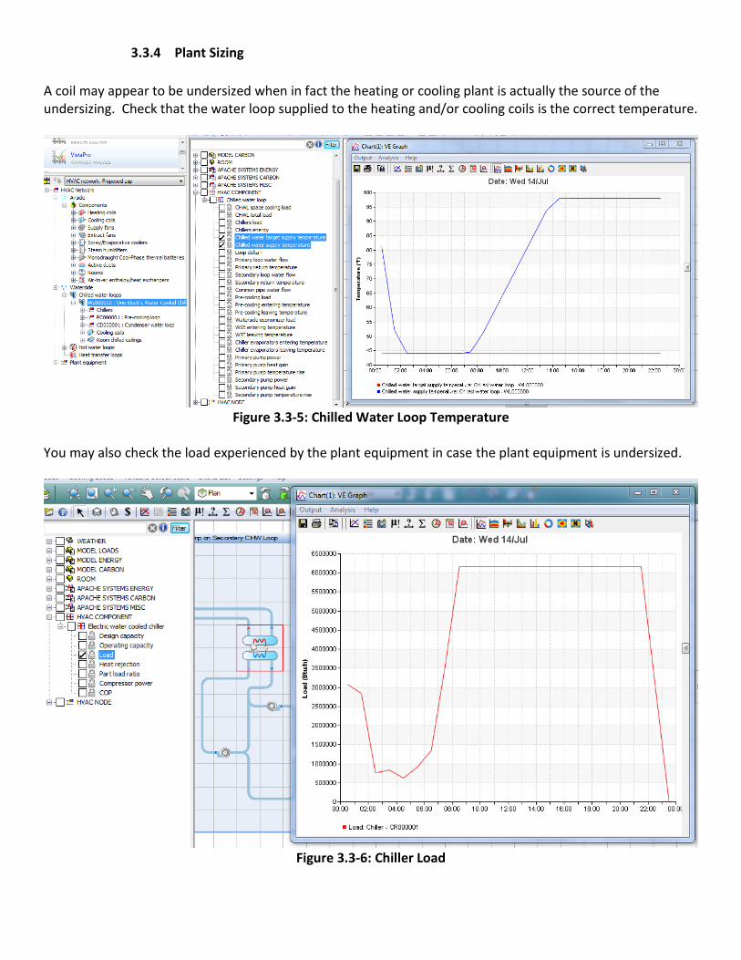
A coil may appear to be undersized when in fact the heating or cooling plant is actually the source of the undersizing. Check that the water loop supplied to the heating and/or cooling coils is the correct temperature.
Figure 3.3-5: Chilled Water Loop Temperature
You may also check the load experienced by the plant equipment in case the plant equipment is undersized.
Figure 3.3-6: Chiller Load
4.0 Simulation Settings
As you interrogate the results of your building simulation to determine the source of unmet load hours, be mindful of your simulation settings.
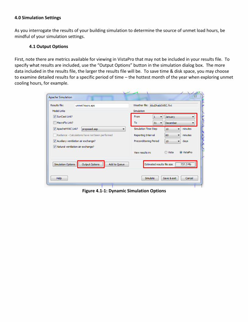
4.1 Output Options
First, note there are metrics available for viewing in VistaPro that may not be included in your results file. To specify what results are included, use the “Output Options” button in the simulation dialog box. The more data included in the results file, the larger the results file will be. To save time & disk space, you may choose to examine detailed results for a specific period of time – the hottest month of the year when exploring unmet cooling hours, for example.
Figure 4.1-1: Dynamic Simulation Options

Figure 4.1-2: Output Options for Dynamic Simulation
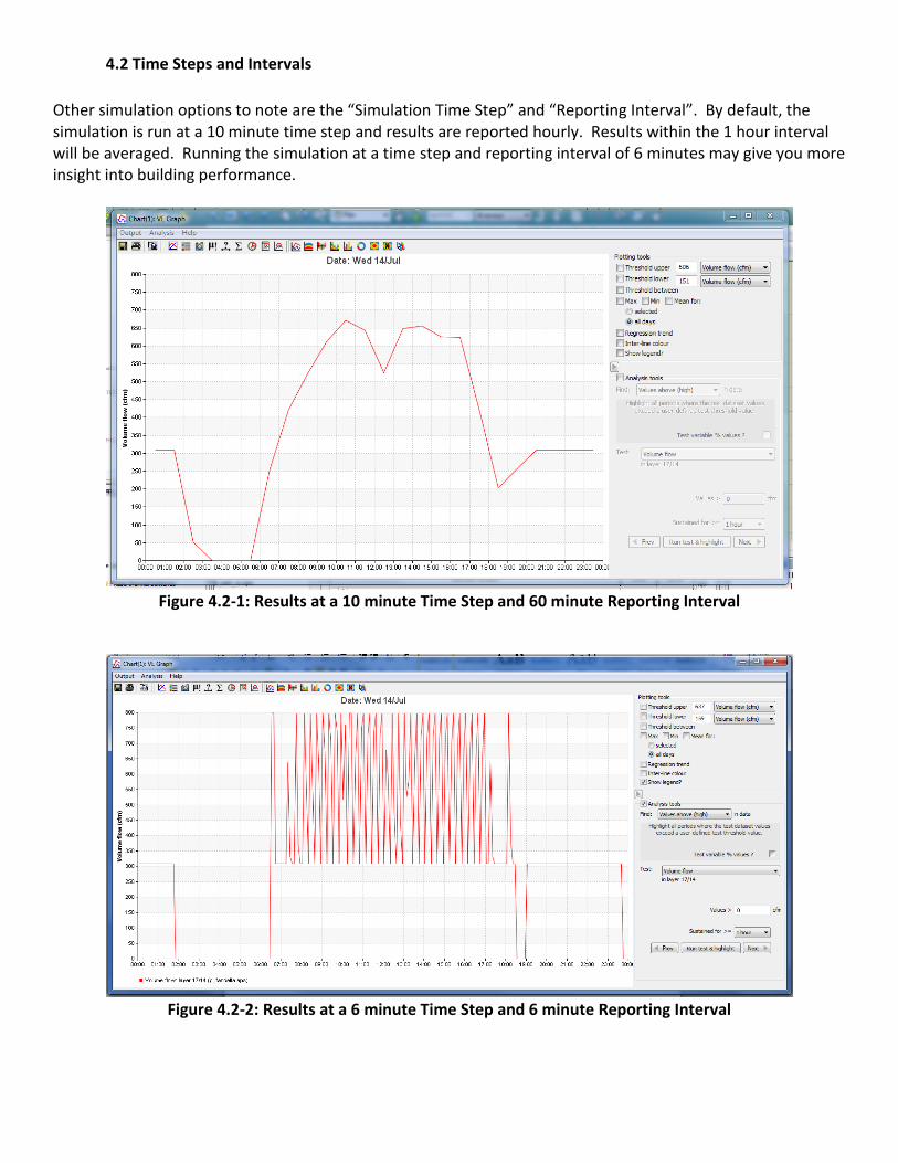
4.2 Time Steps and Intervals
Other simulation options to note are the “Simulation Time Step” and “Reporting Interval”. By default, the simulation is run at a 10 minute time step and results are reported hourly. Results within the 1 hour interval will be averaged. Running the simulation at a time step and reporting interval of 6 minutes may give you more insight into building performance.
Figure 4.2-1: Results at a 10 minute Time Step and 60 minute Reporting Interval
Figure 4.2-2: Results at a 6 minute Time Step and 6 minute Reporting Interval