Embed Size (px)
Citation preview

Student Design Challenge
Page 1 of 26
National Aeronautics and Space Administration
NASA Glenn Research Center
UNIVERSITY STUDENT DESIGN CHALLENGE 2019-2020
AERONAUTICS SPACE
AUTONOMOUS UNMANNED AERIAL SYSTEMS THE NEXT GENERATION OF SPACE TRAVEL
ELECTRIFIED AIRCRAFT PROPULSION SYSTEMS THE LAVA TUBES OF THE MOON
www.nasa.gov 2019 USDC-4
PS-02938-0819

Table of Contents 1.0 Introduction ..........................................................................................................................................3 2.0 Challenge Overview ..............................................................................................................................3
2.1 Aeronautics Challenge I: Automatic Dependence Surveillance Broadcast (ADS-B) Systems for Situational Awareness of Autonomous Unmanned Aerial Systems (UAS)..............................3 2.1.1 Challenge Objective.............................................................................................................4 2.1.2 Mission Performance Requirements...................................................................................5 2.1.3 Conceptual Design...............................................................................................................6
2.2 Aeronautics Challenge II: Integrated Hierarchical Control of Propulsion, Power, and Thermal Management for Electrified Aircraft Propulsion Systems.............................................................9 2.2.1 Challenge Objective...........................................................................................................10 2.2.2 Performance Requirements ..............................................................................................10 2.2.3 Identification of Heat Loads ..............................................................................................11 2.2.4 Performance of Trade Study .............................................................................................11 2.2.5 Design Iteration .................................................................................................................11 2.2.6 Potential Resources...........................................................................................................11
2.3 Space Challenge I: Enabling the Next Generation of Space Travel .............................................12 2.3.1 Challenge Objective...........................................................................................................12 2.3.2 Mission Performance Requirements.................................................................................12 2.3.3 System Design ...................................................................................................................13
2.4 Space Challenge II: Exploring and Utilizing the Lava Tubes of the Moon ...................................14 2.4.1 Challenge Objective...........................................................................................................14 2.4.2 Mission Performance Requirements.................................................................................14 2.4.3 Potential Resources...........................................................................................................16
3.0 Challenge Details.................................................................................................................................16 3.1 Schedule and Milestones ............................................................................................................16 3.2 Judges and Judging......................................................................................................................17 3.3 Challenge Scoring ........................................................................................................................17 3.4 Final Submission and Final Presentations (Virtual Culmination) ................................................18 3.5 Culminating Event .......................................................................................................................18
4.0 Competition Rules and Requirements ................................................................................................18 4.1 Eligibility and Registration...........................................................................................................19 4.2 Rules and Considerations............................................................................................................19
5.0 Data Submission..................................................................................................................................20 5.1 Format.........................................................................................................................................20 5.2 Method........................................................................................................................................20 5.3 Presentation Package..................................................................................................................20
6.0 Roles and Responsibilities...................................................................................................................20 6.1 Role of Faculty Advisor................................................................................................................20 6.2 Role of Technical Experts ............................................................................................................20
Appendix A—Acronyms and Abbreviations..................................................................................................22 Appendix B—Presentation of Written Report ..............................................................................................23 Appendix C—Submission Release Form .......................................................................................................25
GRC—University Student Design Challenge Page 2 of 26

1.0 Introduction
Research and technology (R&T) development of innovative aeronautics- and space-related
technologies at NASA Glenn Research Center (GRC) dates back to 1941. The Center invites teams
of undergraduate students to get involved in its R&T efforts by participating in the fourth-year
implementation of its sponsored University Student Design Challenge (USDC–4) during the 2019– 2020 academic year. The USDC–4 comprises two aeronautics-themed projects and two space-
themed projects, all of which encourage teams of participating students to use out-of-box
approaches to solve specific problems to benefit NASA mission needs.
Eligibility for the USDC–4 competition extends to full-time junior- or senior-year undergraduate
students in accredited U.S. academic institutions who are enrolled in multidisciplinary majors in
science, technology, engineering, arts, and mathematics (STEAM) disciplines. Equally eligible are
students majoring in economics, marketing, graphic arts, or other disciplines that would aid in
successful execution of the Challenge projects. Each team of participating students is required to
have an on-campus faculty advisor. The team of students will have access to GRC subject matter
experts (SMEs) as off-campus technical mentors to complement on-campus faculty advisors.
Like past year offerings, the USDC–4 promotes participation through multidisciplinary teams of
students with STEAM majors to address societal needs for an optimal use of technical and
employable skills to drive and sustain workplace productivity. Using the resourcefulness of students
with diverse knowledge will increase the ability and creativity of the teams and foster team-building
and communication skills which, in turn, can enhance workplace productivity. The Design Challenge
encourages a multidisciplinary view of knowledge resulting from varied ideas and feasibilities.
2.0 Challenge Overview
The USDC-4 presents four Design Challenge options, two focused on Aeronautics and two on
Space:
❖ Aeronautics Challenge I: Design a low-power automatic dependence surveillance
broadcast (ADS-B) system for small unmanned aerial systems (UAS)
❖ Aeronautics Challenge II: Build and demonstrate a model of an electrified aircraft
propulsion (EAP) design
❖ Space Challenge I: Develop a concept for the first real interstellar mission
❖ Space Challenge II: Create robotic systems to explore lava tubes on the Moon for human
habitation
2.1 Aeronautics Challenge I: Automatic Dependence Surveillance Broadcast (ADS-B) Systems for Situational Awareness of Autonomous Unmanned Aerial Systems (UAS)
The evolution of autonomous systems will transform aviation operations and provide
improvements in safety, efficiency, and flexibility of operations to increase the capacity,
GRC—University Student Design Challenge Page 3 of 26

robustness, and flexibility of the National Airspace System. Additional benefits will be realized
through new uses of the airspace, enabled by advances in autonomy such as advanced UAS
operations. Society will gain high confidence in autonomous aviation systems, and large-scale
autonomous systems will achieve goals specified at levels of system governance and
sustainability. Goals will include system-level maintenance, healing, and protection. Systems will
be interconnected and will rely on distributed sensor networks. System elements will be
distributed and collaborative, enabling unprecedented efficiency, agility, robustness, and
resilience.
Communications connectivity requires radios, but radio frequency limitations are forcing
aviation communications higher and higher in the spectrum. The need for increased
communication and information exchanges requires an increasing bandwidth. The student team
designs are expected to solve the bandwidth problem.
2.1.1 Challenge Objective
The objective of this project is to build an ADS-B system for small UAS, inclusive of the
additional features of authentication of the transmissions, call grouping of secondary messages,
and relaying of highly desirable messages. Minimizing the system mass and power consumed
enables a more cost-effective detect-and-avoid payload.
Participating students are asked to create designs for an ADS-B-style system, with provisions
for ground station as infrastructure injection point, electric UAS aircraft vehicle requirements,
communication requirements, traffic system management, and safety.
Other considerations of this ADS-B system for small UAS are as follows:
❖ Assurance of safety message repetition rates
❖ Communications safety margin required for operation in non-clear air (rainy day or fog)
❖ Communication with nearby vehicles of secondary communications payloads (relay
functions)
❖ Determination of an optimum bandwidth
❖ Determination of the optimum size, weight, and power (SWaP) for the operational
capabilities based on the frequency, bandwidth, and required operational needs for
detect and avoid
Important characteristics to address include the following:
❖ State messages concatenation with secondary communications
❖ Authentication of state messages
❖ Energy consumption
❖ Tradeoffs in ADS-B energy consumption, maximum speed, and flight duration
GRC—University Student Design Challenge Page 4 of 26
Small UAS will require low-power detection, avoidance, and communications capabilities.
This effort is to design a low-power ADS-B system for small UAS aircraft traveling less than 55
mph and using the 80- to 90-GHz radio frequency spectrum.
The criteria for this Challenge can be divided into two categories: system design and system
performance. The system design criteria relate to how well the ADS-B data links integrate into
the current environment, e.g., compatibility with other avionics systems. System performance
criteria are designed to describe how well the system will achieve the ADS-B objectives, and in
terms of the applications it is expected to support.
In order to evaluate system performance, two scenarios are chosen as representative of
future environments; they are high- and low-density environments. The two types of
environment are chosen to permit comparison of the ADS-B data links in several different air
traffic situations. Example environments are as follows:
❖ High-air-traffic-density scenario, such as San Francisco/Oakland, California, with a total of
3,000 UAS aircraft
❖ Low-density scenario, with a total of 360 UAS aircraft, city transitioning to rural area,
exemplified by the Cleveland metro area
All UAS aircraft are assumed to be equipped with the ADS-B system and are uniformly
distributed in the horizontal plane within a circle of 400 nautical miles, and varying altitudes from
100 to 3,000 feet above surface. Moreover, the practical implementation of these electric air
vehicles requires leveraging new flight-weight technologies and adapting existing concept of
operations (ConOps) and air traffic management to support the autonomous operations.
This Design Challenge project requires the conceptual development of an ADS-B system for
small UAS that will use their service provider direction and command and control (C2)
communications system for strategic operational control, and will use the ADS-B system for
short-range tactical decisions involving vehicle-to-vehicle and vehicle-to-infrastructure
communications, collision avoidance, and situational awareness.
2.1.2 Mission Performance Requirements
Starting assumptions:
❖ Spectrum band requirements: 90 GHz and 100 MHz bandwidth
❖ Vertical polarization
❖ Reference universal access transceiver (UAT) functional parameters: 1 message per
second, 4 message types, all with state information
❖ Communication link reliability needed is 95%. Operational reliability required is 99.999%.
❖ Terrain and collision avoidance system (TCAS) functionality requires class-size and class-
weight information exchange to determine actions
❖ UAS speed is 55 mph
GRC—University Student Design Challenge Page 5 of 26

❖ 3-dB communications link margin minimum required for operations
❖ 0.5 watts continuous drain on the UAS
❖ Link closure required for sensitivity-level systems is –93 dBm. Nominal sensitivity of
approximately –97 dBm.
Each student design team should consider how their respective design can satisfy the
requirements of the scenario, and each team should determine gross vehicle performance
requirements, range, and airspeed. The mission implies that the aerial system must meet the
following technical requirements for communications:
❖ UAS must be controllable at all times during operations via use of a ground-to-air
communications link.
❖ UAS shall be able to react, avoid, and return to instructed flight path.
❖ UAS shall be able to transmit its position and UAS airframe identification in the
operational space.
❖ UAS shall be able to perform emergency return home over a preset flight path or safely
land upon loss of communication with the control network during autonomous operation.
❖ UAS shall not transmit signals outside of its allocated spectrum at any time.
2.1.3 Conceptual Design
❖ Define mission by Tuesday, November 12, 2019, and specify
➢ Sample electric UAS capability and required municipal airport infrastructure
➢ Payload, range, and speed
➢ Market research (societal impact, public acceptability of electric UAS air vehicles, etc.)
❖ Begin vehicle design by Monday, December 9, 2019, and specify
➢ Airframe selection of UAS
➢ Electrical systems and their thermal management
➢ Other major systems and subsystems
➢ Weight and balance assessment of the new system on UAS
➢ Performance analysis of UAS
If gaps or shortfalls in weight or performance are predicted by the analysis, additional
technologies may be proposed and used to close the vehicle design. Student teams should be
prepared to define what the additional technologies are and how they will be used.
GRC—University Student Design Challenge Page 6 of 26
❖ Importance of Radio Frequency Communication
Radio frequency (RF) communication is the most optimized method for reliable command
and control, and data transmission and reception. RF systems are small and lightweight, with low
power consumption, and are capable of establishing robust communication links over very
specific frequencies.
❖ Factors Limiting Range of Wireless Link
The range of a wireless link is limited by a number of factors. The path loss itself will diminish
the signal when distance increases, and obstacles in the line of sight can give additional
attenuation. Also, other radio transmissions in the operational environment can interfere with
the command/control/data signal. If the interfering signals occur in the same frequency as the
wireless link, it will be observed as noise. This phenomenon reduces the signal-to-noise ratio,
causing command and control issues, as well as noisy video images, while limiting the range of
the link. This problem can be mitigated by using a channel that is far away in frequency from the
interferer or by physically moving the receiver and antenna. There are other sources of
interference that manifest themselves as powerful signals outside the link. Such signals can
penetrate weak front-end channel filtering and affect the performance of the low-noise amplifier
(LNA). These signals are typically radars, broadcast towers, or military radios. The best course of
action here is to operate outside their coverage area.
❖ DO–160G Electromagnetic Interference (EMI) Compliance
The choice of communication equipment can also affect the mass of the entire vehicle. For
example, the automatic direction finder (ADF) radio operates in frequency ranges from 190 KHz
to 1 MHz. The airplane equipment cannot interfere with ADF radio. This explains why the DO– 160G document, Environmental Conditions and Test Procedures for Airborne Equipment,
published by the Radio Technical Commission for Aeronautics (https://do160.org/), has
conducted and radiated emission requirements that start at the low 190-Hz frequency. Currently,
the ADF radio is optional equipment for airplanes. Many airlines select this option, thereby
resulting in installation of ADF radio in many modern airplanes. A considerable number of 787,
777, 777X and older airplanes use the ADF radio. The low-frequency range of the radio results in
larger and heavier filters in power electronics. At the megawatt power level, the yielded mass
can result in less effective payload capacity.
An additional objective of the Challenge project is to use model-based systems engineering
methods to define and refine the systems feasibility for large-scale deployment.
❖ Areas of high interest (weighted)
➢ Power consumed on board the UAS; watts RF/DC consumed. Weight of 5
➢ Frequency reuse plan. Weight of 2
GRC—University Student Design Challenge Page 7 of 26

➢ Current TCAS/UAT minimum message set. Weight of 1
➢ Current TCAS/UAT minimum message set authentication. Weight of 2
➢ Relay function allows greater visibility and message forwarding to adjacent systems.
Weight of 3.
➢ Improvements to fundamental system/design. Weight of 4; decreased power
consumed, increased capacity, or increased reliability.
❖ Figure of Merit (FOM)
➢ FOM of 10 for a system that closes for the communication use case
➢ FOM of 5 for least consumed power
➢ FOM of 3 for maximum margin in decibels
➢ FOM of 2 for defining the UAS reaction time and margins in seconds
❖ Tool Used
➢ Cameo Systems Modeler, SysML, is a modeling tool for model-based systems
engineering
❖ Output
➢ Use case model
○ Derived requirements
○ Constraints
➢ Free space link budget, IF-77 Electromagnetic Wave Propagation Model (Gierhart-
Johnson)
➢ UAV implementation link budget: Receive noise chain analysis and DC power analysis
➢ Optimized parameters: Using the Monte Carlo analysis tool, which is built in to Cameo.
This is to get size, weight, and power (SWaP) and performance. Note that the receiver
noise chain analyses can be done by using any desired tool.
❖ Deliverables
Among the expected deliverables are:
➢ Any assumptions made during the design process, also noted in model
➢ Refined design requirements, From-To format
➢ Optimized models in Cameo Systems Modeler, SysML
➢ PowerPoint (PPT) presentation of final design
GRC—University Student Design Challenge Page 8 of 26

2.2 Aeronautics Challenge II: Integrated Hierarchical Control of Propulsion, Power, and Thermal Management for Electrified Aircraft Propulsion Systems
Electrified aircraft propulsion (EAP) systems have the potential to revolutionize air travel in
the coming generation. This is a time of disruptive change not seen since the advent of the
turbine engine; nontraditional participants are entering a mature market space with very
unconventional aircraft designs. However, traditional market participants, recognizing the threat,
are responding with system architectures and concepts of their own. All these activities focus on
the fundamental promise of EAP, namely, to provide new design flexibility that can open new
markets and produce viable system-level benefits while reducing fuel burn, emissions, and noise.
As with any disruptive technology, propulsion electrification suffers from performance issues
in some of the underlying electric components. As a result, there is tremendous research activity
focusing on many critical technologies. In reality, no one really knows what viable electrified
propulsion concept (Fig. 1) will result in a feasible product for commercial aviation. However, two
facts remain clear for the near future: hydrocarbon fuels are the densest form of storing energy,
and the turbine engine is the most efficient means of producing power.
Figure 1. Electrified Aircraft Propulsion Architecture
GRC—University Student Design Challenge Page 9 of 26

Given this outlook, it is reasonably expected that near-term propulsion system designs will
be based on some type of combination of electric components and turbomachinery. Another
expectation is that system integration and operability will be fundamentally challenging. This is
because EAP systems, which consist of a turbine engine, an electrical power system, and a
thermal management system, operate on time scales covering six orders of magnitude. In
addition, the components are highly multidisciplinary and are generally sourced by different
organizations. Therefore, the integrated hierarchical control of the engine, power, and thermal
management systems is a significant technology to be developed and explored.
2.2.1 Challenge Objective
The objective of this project is to integrate the three major systems of an electrified
propulsion design that comprises a turbine engine, an electric power system, and a thermal
management system. The engine and power systems will be defined by NASA. However, the
thermal management system design will not close (i.e., will not produce any viable vehicle-level
benefits to justify the use of EAP) without new advances in technology. Identifying and resolving
the technology gaps more effectively than efforts by competitors will differentiate a successful
team’s design and the ultimate success of new products.
2.2.2 Performance Requirements
Each multidisciplinary team is expected to build a simulation model of their electrified
propulsion system. NASA will provide details on architecture, individual power and propulsion
components, and constraints. The model will be used to analyze and document the system
performance, identify weaknesses, and improve the design. Problem areas are to be redesigned
in an iterative fashion until the system closes and a realistic design is achieved.
The model developed under this Challenge should be demonstrated in a simulation
environment, utilizing tools that provide dynamic simulation capability sufficient to capture the
interaction of the power, propulsion, and thermal management systems. The use of popular,
widely available codes such as the NASA-developed open-source software T-MATS and EMTAT
(to be released), Simulink (MathWorks), etc., is strongly encouraged.
Among the important characteristics to include are the following:
❖ Power
❖ Stability
❖ Operability
❖ Controllability
❖ Thermal management
GRC—University Student Design Challenge Page 10 of 26

2.2.3 Identification of Heat Loads
After building the EAP model, teams will identify and analyze heat loads across the
turbomachinery and electrical power systems on a component-by-component basis using a
common mission profile provided by NASA. The heat loads will need to be managed to avoid
maintenance and reliability issues, as well as potentially catastrophic system failure.
2.2.4 Performance of Trade Study
Using model data, teams will perform trade studies to analyze how component efficiencies
affect system performance. With this information, teams will identify the most likely areas for
technology improvement that will enable one to close the team’s design and maximize E!P benefits.
2.2.5 Design Iteration
The thermal management system (TMS) will be the primary differentiator in the EAP design.
Not only must the design close, but it will also be evaluated on how well it minimizes peak
temperatures and overall temperature rise. The TMS must be active and either open or closed
loop. Regardless of the design, the TMS is expected to increase system weight, which will offset
performance improvements; It is critical to properly document the team’s design and support all assumptions, especially if there is a lack of engineering data.
2.2.6 Potential Resources
Adibhatla, Shreeder, et al.: Propulsion Control Technology Development Needs to Address NASA
Aeronautics Research Mission Goals for Thrusts 3a and 4. AIAA Propulsion and Energy Forum.
AIAA-2018-4824. https://ntrs.nasa.gov/archive/nasa/casi.ntrs.nasa.gov/20180005340.pdf
Aircraft Configurations/Technologies.
https://www1.grc.nasa.gov/aeronautics/electrified-aircraft-propulsion-eap/eap-for-larger
aircraft/aircraft-configurations-technologies/
Connolly, Joseph W., et al.: Modeling and Control Design for a Turboelectric Single Aisle Aircraft
Propulsion System.
https://ntrs.nasa.gov/archive/nasa/casi.ntrs.nasa.gov/20180005436.pdf
Jansen, Ralph H.; Bowman, Cheryl; Jankovsky, Amy; Dyson, Rodger; and Felder, James. Overview
of NASA Electrified Aircr aft Propulsion Research for Large Subsonic Transports.
https://ntrs.nasa.gov/archive/nasa/casi.ntrs.nasa.gov/20170012222.pdf
Johnson, Wayne; and Silva, Christopher: Observations from Exploration of VTOL Urban Air
Mobility Designs. 2 018.
https://rotorcraft.arc.nasa.gov/Research/Programs/eVTOL_observations_Johnson_Silva_20
18.pdf
National Aeronautics and Space Administration. NASA Aeronautics Strategic Implementation
Plan. 2017 Update. NP-2017-01-2352-HQ.
https://www.nasa.gov/sites/default/files/atoms/files/sip-2017-03-23-17-high.pdf
GRC—University Student Design Challenge Page 11 of 26

2.3 Space Challenge I: Enabling the Next Generation of Space Travel
The Pioneer and Voyager spacecraft were the first interstellar emissaries from Earth. Though
never intended to survive long enough to execute this type of mission, the Voyagers still have
limited function after more than 40 years of deep space travel and have been able to confirm
that they have crossed the boundary between the solar system and interstellar space.
2.3.1 Challenge Objective
The objective of this project is to apply the lessons learned from the Voyager mission to
develop a concept for the first real interstellar mission. The objective is to develop a mission
concept that can deliver a science payload of at least 50 kg to interstellar space in 20 years or
less, and send data back to Earth for a minimum of an additional 20 years after crossing into
interstellar space. The concept development should determine the spacecraft power, propulsion,
and communications system technologies capable of meeting the noted requirements. The
student team(s) will compare the technology needs against current state of the art and identify
the required steps to extend current capabilities to meet the mission requirements. Include any
Earth-based communications technologies or infrastructure that would require technology
development. Develop a concept for the flight system, including all spacecraft subsystems,
launch requirements, and a concept of operations (ConOps) from launch through end of mission
(at least launch + 40 years).
The team(s) should start by researching the Voyager Interstellar Mission and the systems that
have permitted the spacecraft to operate for more than 40 years. The desired science
measurements and data gathering on the environment of interstellar space should also be
researched, starting with the measurements from the Voyager spacecraft and performing a
literature search on published technical papers on interstellar travel. Finally, the team(s) should
familiarize themselves with the deep space network and its current and planned future
capabilities, as well as high-data-rate communications systems currently being studied under the
auspices of N!S!’s Space Communications and Navigation (SCaN) Program; In addition to meetings with the on-campus faculty advisor, tag-ups should be held regularly
with NASA GRC SMEs who support the project to provide any needed guidance to the university
team(s) of students.
2.3.2 Mission Performance Requirements
Requirements include the following:
❖ Assess trajectory options for the mission, beginning with launch. Gravity assist maneuvers
can be utilized to supplement the delta velocity supplied by the launch vehicle.
Nontraditional spacecraft propulsion systems, or even no spacecraft propulsion system,
should be assessed and factor into the technology development needs to meet mission
requirements.
❖ Determine launch vehicle requirements to support the mission concept.
GRC—University Student Design Challenge Page 12 of 26
❖ Determine the scope of science desired for the mission, and prioritize that science against
instrument mass to fulfill the science objective and mission performance capabilities.
❖ Consider secondary mission objectives on a noninterference basis, with the primary
mission objective of returning data on interstellar space. The secondary mission
objectives would include science within the solar system.
Particular attention should be given to the following considerations:
❖ Autonomy
❖ Communications
❖ Safety
❖ Controllability
❖ Traffic and thermal management
❖ Power and propulsion
❖ Weight
2.3.3 System Design
Final report(s) by the team(s) should include the following:
❖ Spacecraft concept with dimensioned drawings or computer-aided design (CAD)
renderings
❖ A mass equipment list (MEL) containing a mass breakdown of the system to subsystems
and components, with mass growth allowances that depend on the maturity of the
system or component (per ANSI/AIAA S-120A-2015 standard, Mass Properties Control for
Space Systems). A suitable margin should then be applied to the spacecraft as
recommended in the ANSI/AIAA standard.
❖ Power consumption by subsystem/component for each mission phase should be
documented in a power equipment list, with allowances as recommended in the
ANSI/AIAA standard.
❖ All trades, assessments, and analyses should be fully documented in the final report(s) by
the team(s). The final report(s) should capture the decision process and all rationales for
anything that requires the team to make a decision based on pros and cons or to meet a
mission requirement (or requirements derived from the mission requirements).
❖ A Concept of Operations (ConOps) should be created. The ConOps should look at mission
operations, beginning at launch and continuing through the end of the mission.
Communications issues should be considered, including how to achieve communications
with Earth from distances of light-hours to light-days. Given that spacecraft consumables
will be at a premium, teams should determine if the operations can conserve any
GRC—University Student Design Challenge Page 13 of 26

consumables to help ensure a 40-year supply. Will the spacecraft need to do active
navigation in the solar system and in interstellar space? Teams should also consider what
can go wrong during the mission and address how the spacecraft can be designed to
withstand potential failures. Additionally, the ConOps should address the infrastructure
required on Earth to support communications with the spacecraft for the time required
and over the distances involved.
2.4 Space Challenge II: Exploring and Utilizing the Lava Tubes of the Moon
For long-duration human occupation at the lunar surface, the ability to make use of local
resources will be a key development. Human survival will require the extraction of oxygen from
rocks or water collected from the cryogenic bottoms of permanently shadowed polar craters. In
addition, long-term hazards to human health, such as unshielded solar radiation and ions, galactic
cosmic radiation, and meteorite bombardment, will need to be avoided or minimized.
One concept for safely sheltering humans at the lunar surface long term is to take advantage
of the likely existence of empty lava tubes as naturally occurring "caves" to shield our fragile
biology from most of the radiation, avoid habitat or atmospheric containment structure impacts
by meteorites, and even reduce the temperature swing from lunar night to day for the habitat
(about –170 C to 120 C at mid-latitudes on the surface).
2.4.1 Challenge Objective
The objective of this project is to create robotic systems that can enter, explore, and map
subsurface lunar cavities of unknown depth and dimension, and return, if not themselves, then
comprehensive information for human habitation evaluation. Lava tube entry may need to be
through a collapsed roof section ("skylight") or via a partially collapsed horizontal tunnel end.
Also required are concepts for how to use an underground cavity as a habitat and how that
habitat volume would be robotically constructed. The method of habitat construction may affect
which underground spaces would be suitable for use, and those constraints need to be specified.
Design Challenge goals include (1) minimizing the mass of any tools, equipment, or structures
needed to accomplish the lunar tasks and (2) minimizing the physical interaction required by the
astronauts by using thoroughly preplanned, highly engineered approaches and employing
robotics with as much autonomy as practical.
2.4.2 Mission Performance Requirements
For initial construction of a cave-sheltered human habitat by potentially autonomous
robotics, what is the minimum mass and/or number of robots to start (e.g., find and map lava
tubes) and then to begin construction?
Could initial construction be unsupervised (autonomous) for at least a minimal habitat
volume? Would a phased approach be feasible, allowing a human visit at an early stage? How
would that be accomplished, what minimum systems would be required, and how long would
local production of life support consumables take?
GRC—University Student Design Challenge Page 14 of 26

For a full self-contained, long-term habitat for a specified number of humans, questions that
will need to be addressed include the following:
❖ What critical subsystems are required, and how are they affected by cave location, size,
and geometry? For instance, how would maintenance access to support subsystems
occur? How would a minimum required underground volume scale with population?
❖ What power source or sources could be used? Would a long-lived nuclear power plant be
required? Would a combination of solar power and batteries or reversible fuel cells be
sufficient? How do power requirements scale with population?
❖ What communications would be necessary? How would access to the surface and/or
surface mobility be accomplished (if necessary)? How much commerce with Earth (or
other human populations) and related infrastructure (landing pads) would be needed?
❖ Assuming recycling/processing of water and biowastes, what percentage recovery
efficiency must be achieved? If nonrecyclable solid waste is generated, how much (or
what percentage of the waste stream) is it, and what is done with it?
Each of the Design Challenge decisions will affect required launch mass, how long processing
of local materials will take, possible phasing of human arrival, and/or level of robotic autonomy
required. Estimates of the quantities should be documented. Among the important
considerations to address are the following:
❖ Habitat construction
❖ Robotic system designs
❖ Launched mass
❖ Life support requirements
❖ Autonomy impacts
Student teams should address required k ey topics for the following milestone dates:
❖ Define the overall habitat system architecture by November 18, 2019, and specify
➢ Assumptions made in system architecture design and operations approach
➢ Initial habitat capacity when first occupied by humans
➢ Number of launches/landings (at what mass capacity) to achieve habitability
➢ Degree of reliance on local source materials when first inhabitable
❖ Undertake subsystem interdependence analyses by December 9, 2019, to determine
➢ Robotics usage impacts on needed resources, including energy
➢ Minimum energy requirements per human inhabitant for basic life support
(nonrenewable)
GRC—University Student Design Challenge Page 15 of 26

➢ Scaling of life support energy required with degree of recycling (e.g., for hydroponics,
greenhouse lights, etc.)
➢ Additional infrastructure and habitation buildout resource requirements, both local
and landed mass
If shortfalls in capabilities are predicted using current state of the art, identify what additional
technologies may be required to close the design.
2.4.3 Potential Resources
Duke, Michael B.; Mendell, Wendell W.; and Roberts, Barney B.: Strategies for a Permanent Lunar
Base. https://www.chicagospace.org/strategies-for-a-permanent-lunar-base/
Heiken, Grant H.; Vaniman, David T.; and French, Bevan M., eds: Lunar Sourcebook. 1991,
Cambridge University Press.
https://www.lpi.usra.edu/publications/books/lunar_sourcebook/
Järvstråt, Niklas; and Toklu, Y. Cengiz. (2004). Design and Construction for Self-sufficiency in a
Lunar Colony.
https://www.researchgate.net/publication/228918710_Design_and_Construction_for_Self
sufficiency_in_a_Lunar_Colony
Lewis, John S.; Matthews, Mildred Shapley; and Guerrieri, Mary L., eds: Resources of Near-Earth
Space. University of Arizona Press, Space Science Series.
https://www.amazon.com/Resources-Near-Earth-Space
Science/dp/0816514046/ref=sr_1_1?qid=1563818585&refinements=p_27%3AMary+L.+Gue
rrieri&s=books&sr=1-1&text=Mary+L.+Guerrieri
O’Handley, Douglas: Final Report on System Architecture Development for a Self-Sustaining
Lunar Colony. https://space.nss.org/media/2000-System-Architecture-Development-For-A
Self-Sustaining-Lunar-Colony.pdf
Scharmen, Fred: What Will Humans Really Need in Space?
https://slate.com/technology/2019/06/chen-qiufan-space-leek-response-agriculture.html
Tate, Karl: How Moon Base Lunar Colony Works (Infographic). Space.com.
https://www.space.com/21588-how-moon-base-lunar-colony-works-infographic.html
3.0 Challenge Details
The following information applies to both the Aeronautics and Space components of the
Challenge.
3.1 Schedule and Milestones
Students must register for the Design Challenge competition between September 16 and
October 18, 2019, the registration deadline. Registered students are required to participate in
the following scheduled activities and deliverables:
GRC—University Student Design Challenge Page 16 of 26

10/18/2019 Registration Deadline
10/25/2019 Submission Release Form Deadline
11/6/2019 Aero Projects Kickoff Presentation and Introductory Workshops I
and II
11/7/2019 Space Projects Kickoff Presentation and Introductory Workshops I
and II
11/18/2019 to 11/19/2019 Aero Projects Virtual Student Team Meetings I and II with GRC
SMEs
11/20/2019 to 11/21/2019 Space Projects Virtual Student Team Meetings I and II with GRC
SMEs
1/22/2020 to 1/23/2020 Virtual Preliminary Design Review and Team Photo
2/19/2020 to 2/20/2020 Virtual Pre-Culminating Design Review and Team Action Photo
3/13/2020 Final Design Report and Team Project Video Deadline
3/23/2020 to 3/27/2020 Final Presentations – Teams Present Final Outcomes
4/13/2020 Winners Announced
6/11/2020 GRC On -Site Culminating Event – Winning Teams Invited
3.2 Judges and Judging
Each USDC–4 Challenge project will have three independent judges: two subject matter
experts (SMEs) and one GRC Office of Education staff member with technical expertise regarding
the Challenge projects. Each team’s final report and presentation will contribute heavily to the
selection of the Challenge winners. The judges, with their collective final decision authority, will
select the winning team based on
❖ Challenge scoring (Section 3.3)
❖ Compliance with USDC–4 requirements and rules (Section 4)
❖ Compliance with USDC–4 data submission guidelines (Section 5)
Judging will be conducted via videoconference using standardized criteria on a scale of 1 (low,
poor) to 5 (high, superb). Judges will provide scores to each team within 3 weeks of the final
presentations.
3.3 Challenge Scoring
Challenge scores will be based on the judges’ assessment of each team’s creativity and
ingenuity, as well as the feasibility and practicality of their approach, in addressing and/or solving
the challenges and issues presented in the USDC–4; Each team’s final submission should reflect a high level of quality and effort. Judges are allotted considerable discretion in Challenge scoring.
GRC—University Student Design Challenge Page 17 of 26

Where data support in a presentation is evident, its inclusion will be factored into the eventual
score for any team.
3.4 Final Submission and Final Presentations (Virtual Culmination)
Each participating team of students shall email their Final Design Report to grc-university
[email protected] no later than March 13, 2020. Team Project Videos are also due
on March 13, 2020; see Section 4.2 for details.
Each team shall make a 20- to 30-minute virtual presentation on their design to the USDC–4
judges between March 23 and March 27, 2020.
3.5 Culminating Event
Winners will be announced on April 13, 2020. Each of the winning and runner-up teams and
their respective faculty advisors will travel to Glenn Research Center in Cleveland, Ohio. First-
place teams of the Aeronautics and Space projects will present their design highlights to the GRC
NASA employees and summer interns and faculty fellow. The winning teams will have a
networking luncheon with NASA managers, as well as participate in a tour of selected GRC
facilities.
Pending availability of funds, NASA (or its business partner) will secure and coordinate travel
arrangements with expenses up to $5,000 per team awarded to the winning and runner-up teams
if their academic institutions are located outside a 50-mile radius of GRC. Lawful permanent
residents of the United States and non-U.S. citizens on the winning and runner-up teams shall
adhere to GRC access policies. Please note that GRC may not be able to provide access to some
international visitors, or may need to restrict access.
4.0 Competition Rules and Requirements
Each team’s final submission must focus on GRC’s areas of expertise and address the
following considerations:
❖ For Aeronautics Project I: Power, Stability, Operability, Controllability, and Thermal
Management
❖ For Aeronautics Project II: Power, Autonomy, Communications, Safety, Controllability,
Traffic and Thermal Management, and Weight and Propulsion
❖ For Space Project I: Power, Autonomy, Communications, Vehicle Requirements, and
Trajectory Options
❖ For Space Project II: Autonomy, Habitat Construction, Robotic System Designs, Launched
Mass, and Life Support Requirements
Student teams must follow USDC rules regarding eligibility, registration, design, deliverables,
monitoring, and review.
GRC—University Student Design Challenge Page 18 of 26

4.1 Eligibility and Registration
Each team must
❖ Comprise full-time undergraduate students in their junior or senior year.
❖ Be enrolled in an accredited U.S. (including Puerto Rico) academic institution.
❖ Have a U.S. citizen as Team Lead/Point of Contact (POC). Other members of each team
must be U.S. citizens or a combination of U.S. citizens and lawful permanent residents of
the United States.
❖ Attend the Virtual Kickoff Meeting of their focused Aeronautics or Space project.
❖ Comprise no fewer than 3 individuals and no more than 6.
❖ Have Team Leads/POCs register all team members through their academic institution no
later than 11:59 p.m. EST on October 18, 2019.
❖ Have an on-campus faculty member volunteer serving as advisor for the complete
duration of the USDC–4.
❖ Have all their members complete the Submission Release Form for University Student
Design Challenge, located in Appendix C, and return the completed form via email to grc
[email protected] no later than 11:59 p.m. EST on October 25,
2019.
4.2 Rules and Considerations
Each team participating in the USDC–4 agrees to
❖ Grant NASA unimpeded visitation to its operations and/or worksites to allow inspection
of its conceptual design, if needed. NASA may use such visits (virtual or in-person) to verify
any team’s compliance with stated USDC–4 rules.
❖ Permit NASA to review any USDC-related information and/or data the team has withheld.
NASA may use such data to validate a team’s final submission;
❖ Provide the following in support of social media and press releases:
➢ Team Project Video: A 2- to 3-minute video that shows the team building or
developing their design from start to finish. Use creativity to tell the story of the
project. Avoid having one person speaking to the camera the entire time. Do not send
a video version of a PowerPoint presentation. Send video as an MP4 file to a medium
that will be identified at a later date (e.g., Dropbox or Google Drive). Due date is
March 13, 2020.
➢ Two photos: One photo of the team with the faculty advisor and one photo of the
team in action (e.g., creating design drawings, charts, or quantitative figures). Photos
GRC—University Student Design Challenge Page 19 of 26

should be at least 1200 pixels wide by 600 pixels high. Photos cannot be blurry or low
resolution. No file sizes greater than 3 MB.
5.0 Data Submission
Each team must follow the submission guidelines below.
5.1 Format
Each team’s written report must not exceed 12 pages (excluding appendices and
bibliography) and must be received via email by the GRC O ffice of Education no later than 11:59
p.m. EST on March 13, 2020. The report shall follow the template in Appendix B.
Presentation and document submissions shall be in Adobe portable document format (PDF)
or PowerPoint (PPT), although PDF is preferred. Any handwritten or drawn document(s) shall be
scanned and delivered via PDF with a minimum resolution of 400 by 400 dots per inch (dpi).
5.2 Method
All USDC–4 material, including each team’s final submission, shall be sent to this email
address: [email protected].
5.3 Presentation Package
Each Presentation Package shall include a cover page bearing the title of the Presentation
Package, each team member’s name, the faculty advisor’s name, the academic affiliation and location, and express reference to “2020 GRC University Student Design Challenge (USDC–4).” POCs for each team shall place their initials next to their name.
6.0 Roles and Responsibilities
There are distinct responsibilities for on-campus faculty advisors and GRC-based technical
experts, as noted in the following subsections.
6.1 Role of Faculty Advisor
The on-campus faculty advisor
❖ Advises students on Challenge project, on campus
❖ Guides students to achieve goals of Design Challenge
❖ Refers students to appropriate institutional resources
❖ Confirms his or her support via email to [email protected]
6.2 Role of Technical Experts
GRC’s highly skilled workforce includes world-renowned researchers, among them rocket
scientists, engineers, physicists, and chemists as well as aviation specialists and others, many of
GRC—University Student Design Challenge Page 20 of 26

whom will serve as technical experts throughout the Design Challenge. Students will be
immersed in NASA-related research and engineering through interaction with these talented,
dedicated, and passionate employees. With countless specializations in numerous fields, the
employees at GRC share one goal: working for the public in support of N!S!’s mission; Technical experts have the following roles and responsibilities:
❖ Serve as content specialists
❖ Serve as Design Challenge judges
❖ Respond to team questions
❖ Review projects
❖ Debrief teams if requested
GRC—University Student Design Challenge Page 21 of 26
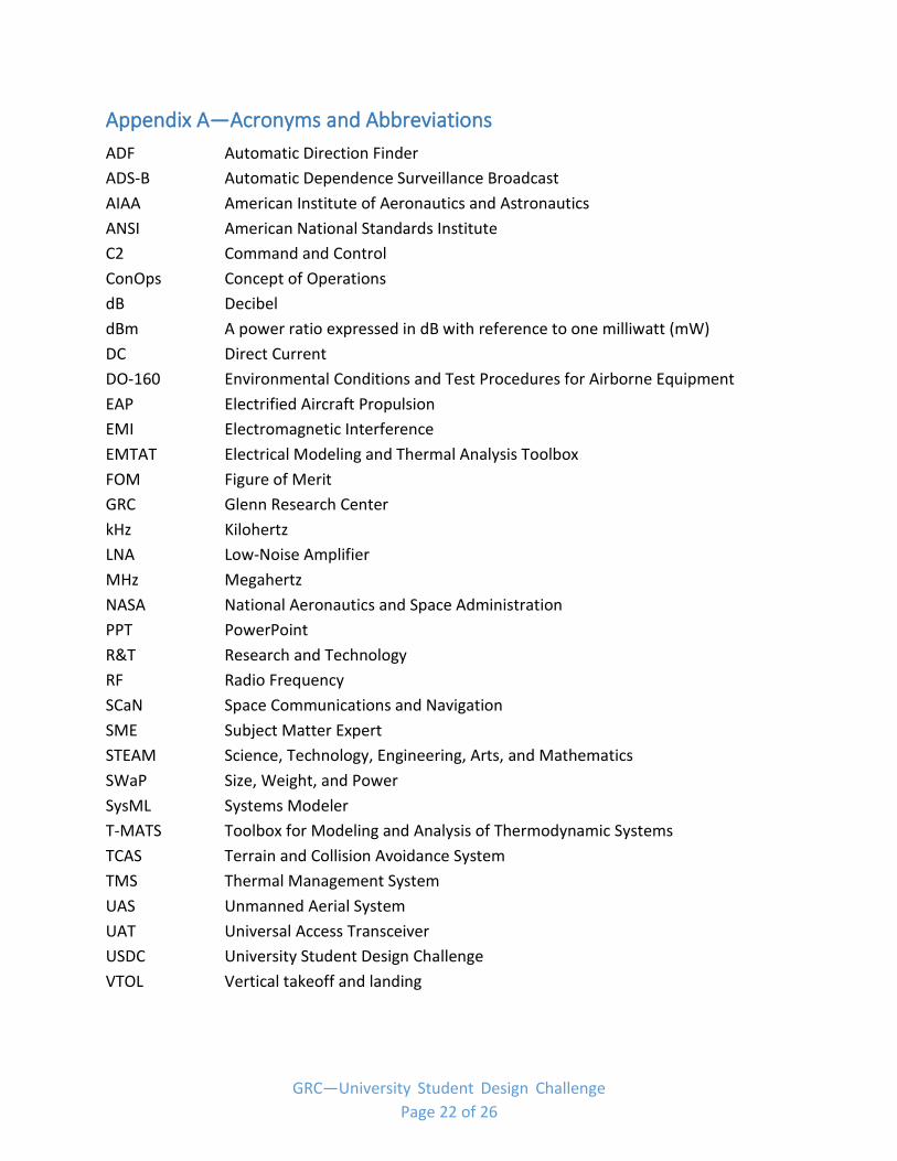
Appendix A—Acronyms and Abbreviations
ADF Automatic Direction Finder
ADS-B Automatic Dependence Surveillance Broadcast
AIAA American Institute of Aeronautics and Astronautics
ANSI American National Standards Institute
C2 Command and Control
ConOps Concept of Operations
dB Decibel
dBm A power ratio expressed in dB with reference to one milliwatt (mW)
DC Direct Current
DO-160 Environmental Conditions and Test Procedures for Airborne Equipment
EAP Electrified Aircraft Propulsion
EMI Electromagnetic Interference
EMTAT Electrical Modeling and Thermal Analysis Toolbox
FOM Figure of Merit
GRC Glenn Research Center
kHz Kilohertz
LNA Low-Noise Amplifier
MHz Megahertz
NASA National Aeronautics and Space Administration
PPT PowerPoint
R&T Research and Technology
RF Radio Frequency
SCaN Space Communications and Navigation
SME Subject Matter Expert
STEAM Science, Technology, Engineering, Arts, and Mathematics
SWaP Size, Weight, and Power
SysML Systems Modeler
T-MATS Toolbox for Modeling and Analysis of Thermodynamic Systems
TCAS Terrain and Collision Avoidance System
TMS Thermal Management System
UAS Unmanned Aerial System
UAT Universal Access Transceiver
USDC University Student Design Challenge
VTOL Vertical takeoff and landing
GRC—University Student Design Challenge Page 22 of 26
Appendix B—Presentation of Written Report
Title of Report (Cover Page)
First A. Author, Second B. Author, Jr., Third Author
Academic Affiliation, City, State, Zip Code
Faculty Advisor/Academic Affiliation
2020 GRC University Student Design Challenge (USDC–4) NASA Glenn Research Center
Cleveland, Ohio
GRC—University Student Design Challenge Page 23 of 26

Title of Report (Title Page) The title of your paper should be typed in bold, 18-point type, with capital and lowercase letters,
and centered at the top of the page.
Abstract
The abstract should appear at the beginning of your paper. It should be one
paragraph long and complete in itself (not an introduction). It should indicate
subjects dealt with in the paper and state the objectives of the investigation.
Newly observed facts and conclusions of the experiment or argument discussed
in the paper must be stated in summary form; readers should not have to read
the paper to understand the abstract. The abstract should be bold, indented
(1/2 in.) on each side, justified, and separated from the rest of the document by
two blank lines.
Keywords: Nomenclature:
Body of Paper
For uniformity, 12-point Calibri font is recommended.
Major report headings should be bold, centered, and numbered with Roman numerals. Subheadings should be bold, flush left, and numbered with capital letters. Sub-subheadings should be italic, flush left, and numbered.
Reports should include the following sections:
I. Introduction/Background
II. Methodology/Approach
III. Discussion of Results/Findings
IV. Conclusions/Recommendations
Appendix (if any)
Acknowledgments
References
GRC—University Student Design Challenge Page 24 of 26

______________________________________________________________________________________________ ______________________________________________________________________________________________ ______________________________________________________________________________________________ ______________________________________________________________________________________________
Appendix C—Submission Release Form
SUBMISSION RELEASE FORM FOR
UNIVERSITY STUDENT DESIGN CHALLENGE
Title of Submission:
(“Submission”).
Submitter’s Name:
(“Student”).
Submission Team Members (if applicable) (“Student’s Team”):
Faculty advisor(s) (if applicable):
Name of School
School Address
City State Zip Phone
Grade/Level of Study
I, the Student, certify that the above Submission, including any text and illustrations, and any
ancillary or attendant material, was made, created, or otherwise developed by the Student or the
Student’s Team and was not copied from another work, photograph, illustration, or website or
made, developed, or created by any other person or entity. I understand that the Submission,
including any text and illustrations, and any ancillary or attendant material, will not be returned.
I give permission to the National Aeronautics and Space Administration (NASA) to use,
reproduce, publish, perform publicly, display publicly, prepare derivative works from, and
distribute copies to the public of the Submission, including any text and illustrations, and any
ancillary or attendant material, and the Student’s name, photo, school, and grade/level of study
for any and all purposes deemed appropriate by NASA. NASA may distribute the Submission,
including text and illustrations, and any ancillary or attendant material, through a variety of
GRC—University Student Design Challenge Page 25 of 26
*** *** ** ** *** ***
media, including, but not limited to, print, television, websites, or any other means digital or
otherwise. NASA may also permit a third party to exercise NASA’s rights, including, but not
limited to, the right to display or distribute the Submission, including text and illustrations, and
any ancillary or attendant material, in a manner NASA deems appropriate. If information from
any other person or entity is included in the Submission, including text and illustrations, and
any ancillary or attendant material, it is the Student’s responsibility to obtain the appropriate permissions for use of such information as provided herein.
Student unconditionally releases, discharges, and agrees to save harmless NASA from and
against any and all claims, liabilities, demands, actions, causes of action, costs and expenses,
whatsoever, at law or in equity, known or unknown, anticipated or unanticipated, suspected or
unsuspected, which Student ever had, now has, or may, shall, or hereafter have by any reason,
matter, cause, or thing whatsoever, arising out of Student’s participation or efforts in making,
creating, or otherwise developing the Submission, including text and illustrations, and any
ancillary or attendant material.
This release and any dispute or claim arising out of or in connection with it or its subject matter
or formation (including non-contractual disputes or claims) shall be governed by and construed
in accordance with the laws of the United States of America, and the Student agrees that the
courts of the United States of America shall have exclusive jurisdiction to settle any dispute or
claim that arises out of or in connection with this release.
If any provision, or portion thereof, of this release is, or becomes, invalid under any applicable
statute or rule of law, it is to be deemed stricken, and the rest of this release shall remain in full
force and effect.
Student hereby affirms that he/she is over the age of 18 and has the right to contract in his/her
own name. Student has read the above release prior to its execution and fully understands the
contents thereof. This release shall be binding upon Student and his/her heirs, legal
representatives, and assigns.
(Participant’s Signature) (Date)
* OR *
I, , am the parent or legal guardian of
the Student and have the right to contract for him/her. I have read the above release prior to
its execution and fully understand the contents thereof. This agreement shall be binding
upon me and my heirs, legal representatives, and assigns and those of the subject(s) listed
above.
(Signature of Parent or Legal Guardian) (Date)
GRC—University Student Design Challenge Page 26 of 26