Embed Size (px)
Citation preview
t~av 18 '83'
University of Hawaii at ManoaHawaii Institute of Geophysics
2525 Correa Road. Honolulu, Hawaii 96822Cable Address: UNIHAW
November 15, 1983
Mr. Jerry LesperanceEnergy DivisionDepartment of Planning and
Economic Development335 Merchant St. Rm. 110Honolulu, Hawaii 96813
Dear Jerry:
Enclosed are copies of five papers that discuss the results of the "HGP-AGeotherma1 Wellhead Envi ronmenta1 Monitoring II Contract (No. 14937}. I hopethat these wi 11 provide sufficient information to sati sfy the reportingrequirements on this project.
Should you have any questions regarding these papers please give me acall.
Sin ely yours,,--//)
~~'-,..L--'~/~..0-~--"-~
Donald Thomas
DT:mdencl.
AN EQUAL OPPORTUNITY EMPLOYER

..",
Geoth rmal Resources Council, TRANSACTIONS Vol. 6, October 1982
PROCESS CHEMISTRY MONITORING AT THE HGP-A POWER PLANT:ANALYTICAL RESULTS, PROCESS PROBLEMS AND MODIFICATIONS
Donald M. Thomas
Hawaii Institute of Geophysics2525 Correa Road, Honolulu, Hawaii 96822
ABSTRACT INTRODUCTION
The HGP~A generator plant began operations onJune 12, 1981 and came on-line on a continuousbasis on March I, 1982. During this period process problems were identified and, in most cases,plant modifications have eliminated the difficulties. Silica in the brine was stable at a pH 7.5,however, at a pH above 9.5 deposition of silicawas triggered in a brine disposal system and required abandonment of the hydrogen sulfide abatement process originally proposed for the brinesystem. The steam phase sulfide abatement systemfor standby conditions was 90% effective, althoughsuperheat in the treatment system reduced abatement efficiency. Brine carryover through theseparator was very low; however, scale depositionon the turbine blades resulted in substantialdamage to the turbine. Non-condensable gases inthe condenser were weakly partitioned into theliquid phase, and about 99% were carried into theoff-gas treatment system which was found to beapproximately 99% effective.
Start-up operations at the HGP-A generatorfacility on the island of Hawaii were initiated onJune 12, 1981; the power plant began providingpower to the utility grid on a continuous basis onMarch I, 1982. During this shakedown period andcontinuing to the present, a number of mechanicaland process problems have arisen from the geothermal fluid characteristics or from proposed operational procedures that were incompatible with thegeothermal fluids. Most of the initial problemshave been resolved and modifications are continuing on the plant facility to correct those thatremain.
BRINE PROCESS MONITORING
The HGP-A well, which powers the generatorfacility, has an output capacity of approximately23,000 kg/hr (50,000 Ib/hr) of brine and 23,000kg/hr (50,000 lb/hr) steam. The total fluid flowfrom the well is directed into a centrifugal separator/demistor vessel (Fig. 1) where the steam
-,IIIIIIII__ J
IIII'--
PERCOLATION
POliO
SILICA SETTLING
POliO
UNOERGROlJNO~
rPRESSURE RELIEF .VALVE I
I
gOTHER/1&
RESERVOIR
Fig. 1 HGP-A Geothermal Generator Project steam supply process.
Hawaii Institute of Geophysics Contribution 1268
401

Thomas
TABLE I. MAJOR ELEMENT CHD1ISTRY OF HGP-A FLUIDS (mg/kg)
The hydrogen sulfide emissions in the steamphase from the flash tank were considered sufficiently large to justify the application of abate-
CO
9. 'VI
12.9 'VI
130.5
125.
609
1297
670
964
6/14/81
2/8/82
TABLE II. GAS CHEMISTRY IN HGP-A STEA}l
STEAM PROCESS MONITORING
The steam fraction from the separator, duringplant stand-by conditions, is diverted through apressure reduction valve and into a rock muffler.The non-condensable gas concentrations present inthe steam phase are summarized in Table II. Thesulfide production rate from this well amounts toapproximately ~ a metric ton per day in the steamphase; thus it was necessary to apply hydrogensulfide abatement procedures to the geothermalsteam emitted to the atmosphere. The abatementtechnique applied was to inject a 10% solution ofsodium hydroxide into the low-pressure steam lineupstream of a static mixer spool. This procedurewas found to be about 90% effective at a moleratio of 3 sodium hydroxide to 1 hydrogen sulfide.Although this may not be the peak efficiency forthis system, we did find that substantially increased caustic injection rates provided only aminimal improvement in the abatement efficiency.
The degree of superheat in the steam wasfound to be a very important factor in the efficiency of the hydrogen sulfide abatement procedure.During the initial start-up period, insufficientwater was added to the steam line downstream ofthe pressure reduction valve and as a result,caustic was being injected into a superheatedsteam. Under these conditions, the efficiency ofthe caustic abatement procedures was reduced by30% to 50% and substantial back pressures werecreated (due to solids deposition) throughout thelow-pressure system. The latter effect may haveprecipitated the failure of a temporary port inthe rock muffler box. Further work with the systemindicated that sulfide abatement and system backpressures were optimized with a slight excess(10%-20%) of desuperheat water being injected.Additional testing of this abatement system isplanned.
ment procedures. The proposed process was an adjustment of the brine pH to approximately 10 pHunits immediately downstream of the pressure reduction valve. This procedure was effective in reducing the sulfide emissions from the brine. However, it also destabilized the colloidal silicaformed at pH 8.5; the colloidal suspension rapidlyflocculated to form a moderately viscous sludgehaving a water content of approximately 95% to 99%.The sludge formed was sufficient to fill the silica settling tank in approximately 48 to 72 hoursand, if passed through the settling tank, causedan immediate and drastic reduction in the performance of the percolation ponds. Although a numberof procedures for handling the silica sludge wereinvestigated, none proved to be economically workable, and thus direct caustic injection into thebrine as hydrogen sulfide abatement procedure wasabandoned. Work is currently under way to construct a hood and treatment stack for the hydrogenHul fld,' ('n1lflfl!onH froll1 Lilt' brine rlllHII Link.
402
1233
795
Ca SO:
15.9 50
72. 63
K Mg
148 .061
250 0.1
Na
806
2190
1593
3700
Well Shut In --
12/22/81 3261 1745 281 0.038 58.3 NO 1004
2/5/82 4226 2253 364 0.054 84.4 NO 850
4/5/82 5119
6/17/81
9/4/81
From the separator, the brine is passedthrough a pressure reduction valve into an atmospheric flash tank. The remaining liquid fractionis passed through a silica settling tank and theninto a percolation pond. The steam phase formed ispresently being emitted to the atmosphere. Thebrine phase fed into the low-pressure flash tankcontains approximately 30 ppm hydrogen sulfide andapproximately 60 ppm carbon dioxide; about 90% to98% of these gases are partitioned into the steamphase formed in the flash tank, resulting in anappreciable pH change in the brine (from about 7.4to 8.5). The steam discharge, as a result of thegas loss from the brine, becomes a small but significant source of hydrogen sulfide emissions fromthe plant. The increase in brine pH occasioned bythe gas loss also has significant impact on thesilica present in the liquid phase. Whereas thedissolved silica in cooled (non-flashed) samplesof brine appeared to be stable indefinitely, theincreased pH of the flashed brine triggered silicapolymerization resulting in the formation of amoderately stable colloidal suspension of silicapolymers. Under these conditions, silica precipitation in the silica settling tank is very slow;after nearly five months of flow, the silica cakeon the walls of the pond is less than 2 em thick.
and brine flows are separated at approximately1,200 kPaa (175 psia). The observed major elementchemical composition from the separator is summarized in Table I. Although a detailed interpretation of the fluid chemistry has not been completed,several general observations can be made. Thetotal dissolved solids content has increased substantially since flow was initiated in June 1981.This increase may be the result of increased seawater intrusion into the production aquifers or,alternatively, it may reflect an increasing fraction of steam formation from the single phase reservoir fluid as the flash front migrates awayfrom the wellbore. It is also noteworthy thatsilica concentrations in the brine have decreased,rather than increased, since the early productionflow. The decrease is thought to result from rapidreequilibration of the reservoir silica concentrations to lower temperatures encountered in theflash zone and in the wellbore. If reequilibraLionIs controlling the silleil conccnLriitlonH. It IHprubable that subsLanLlal sIlIca precipiLaLion isoccurring both within the flash zone and in thewellbore; this situation may, in the long term,reduce the output capacity of the HGP-A well.
•Thomas
SEPARATOR
i - - --)lOAD BANK>
r-----------iI II L - - tHElCD SYST£H>
3MWGENERATOR
H,S ABAT£HENT
ATfiOSPHERE
CDOlI HG TOWER
BASIN
~'C;t::===-::t , 1I I I IPERCOlATION
POND
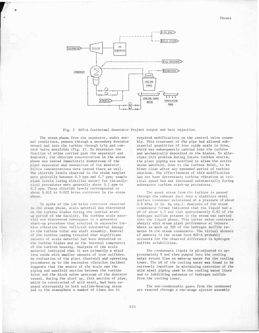
Fig. 2 HGP-A Geothermal Generator Project output and heat rejection.
The steam phase from the separator, under normal conditions, passes through a secondary demistorvessel and into the turbine through trip and control valve manifolds (Fig. 2). To determine thefraction of brine carried past the separator anddemistor, the chloride concentration in the steamphase was tested immediately downstream of theplant separator and downstream of the demistor.Silica concentrations were tested there as well.The chloride levels observed in the steam sampleswere generally between 0.3 ppm and 0.7 ppm; sampleblank levels (using distilled water) for theanalytical procedures were generally about 0.1 ppm to0.2 ppm. These chloride levels corresponded toabout 0.01% to 0.02% brine carryover in the steamphase.
In spite of the low brine carryover observedin the steam phase, scale material was discoveredon the turbine blades during the initial startup period of the facility. The turbine scale material was discovered subsequent to a generatorstart-up procedure that resulted in excessive turbine vibration that inflicted substantial damageto the turbine rotor and shaft assembly. Removalof the turbine casing revealed that significant~nmunts of scale material had been deposited onthe turbine blades and on the internal componentsof the turbine housing. Analysis of the scalematerial indicated that it was primarily a mixediron oxide with smaller amounts of iron sulfides.An evaluation of the plant chemistry and operatingprocedures up to the excessive vibration incidentsuggests that the source of the scale was thepiping and manifold section between the turbineinlet and the block valve upstream of the demistorvessel. During the start up, this section of pipe,which is constructed of mild steel, had been exposed alternately to both sulfide-bearing steamand to the atmosphere a number of times due to
required modifications on the control valve assembly. This treatment of the pipe had allowed substantial quantities of iron oxide scale to form,which was subsequently carried into the turbineand mechanically deposited on the blades. To alleviate this problem during future turbine starts,the plant piping was modified to allow the entiresteam manifold, down to the turbine inlet, to beblown clear after any extended period of turbineshutdown. The effectiveness of this modificationhas not been determined; turbine vibration at critical speed has not increased substantially duringsubsequent turbine start-up procedures.
The spent steam from the turbine is passedthrough the exhaust duct into a stainless steelsurface condenser maintained at a pressure of about0.8 kPaa (6 in. Hg abs.). Analysis of the steamcondensate formed indicated that the liquid had apH of about 4.5 and that approximately 0.6% of thehydrogen sulfide present in the steam was carriedinto the liquid phase. This latter value contrastssharply with steam plant performance at Geyserswhere as much as 30% of the hydrogen sulfide remains in the steam condensate. The virtual absenceof ammonia in the steam from HGP-A probablyaccounts for the observed dIfference in hydrogensulfide solubilities.
The condensate liquid is pH-adjusted to approximately 9 and then pumped into the coolingwater return line as make-up water for the coolingtower. The pH of the cooling water was found to beextremely important in minimizing corrosion of themild st~el piping used in the cooling water linesand to inhibiting emission of hydrogen sulfidefrom the cooling tower.
The non-condensable gases from the condenserare removed through a two-stage ejector assembly
403
L ------"-'

•
•
•
Thomas
and are injected into an incinerator backed by apacked column scrubbing tower. The hydrogen sulfide fraction of the gases is incinerated to sulfur dioxide, which is subsequently removed bysodium hydroxide treatment in the packed column.During the initial start-up of this abatement system, insufficient air flow into the incineratorresulted in an incomplete reaction of the hydrogensulfide to sulfur dioxide, leading to the following reaction: 2H2S + S02 + 3S· + 2H20. Elementalsulfur formed very rapidly, reduced the scrubbercolumn flow capacity, and required a shut down ofthe system for removal and replacement of thetower packing. Modification of the air blower system to provide an excess mole ratio of oxygen inthe incinerator apparently has eliminated thisproblem.
Although the abatement efficiency of the incinerator scrubber was quite high (>99%), thegaseous emissions from the column were found tocarry a significant quantity of sulfur particulates. Because this was considered to be a sourceof visual pollution, piping was installed to transmit the stack gases to the air intake of the cooling tower. Passage of the gas through the coolingwater cascade removed a substantial fraction ofthe sulfur particulate and diluted the remainderto the point that it was not visible in the cooling tower plume. No adverse effects on the coolingtower water from this procedure have been observed.
PRESENT OPERATION
At the present time the power plant isoperating at a capacity of about 2.8 MWE with anoverall plant hydrogen sulfide abatement efficiency of approximately 98%. Work is currentlyunder way to reduce the condenser back pressure to0.5 kPaa (4 in. Hg abs.) or less in order to bringthe plant capacity up to 3 MWE. Modifications arealso under way on the brine steam emission systemthat will attempt to improve the total hydrogensulfide abatement efficiency of the facility tobetter than 99%.
ACKNOWLEDGMENTS
Sampling and analytical assistance of DavidMills, Chuck Fraley, Robert Mitiguy, and RobertKochy, and assistance in the preparation of themanuscript by Leslie Kajiwara and Jan Danek aregratefully acknowledged. This work was supportedby Department of Energy Grant DE-AC03-78ET 28420.
404