Embed Size (px)
Citation preview
University of Washington
Presented by Eric Yost
University of Washington
Electric Pontiac Fiero Project
General: To convert a gas powered ’88 Pontiac Fiero into an electric vehicle able to accelerate from 0–60 MPH in less than 5 seconds.
Specific: Design and integrate the drive train that best meets the requirements of the customer
Problem Statement:Problem Statement:
• Transmission• No transmissionNo transmission
Design Problems:Design Problems:
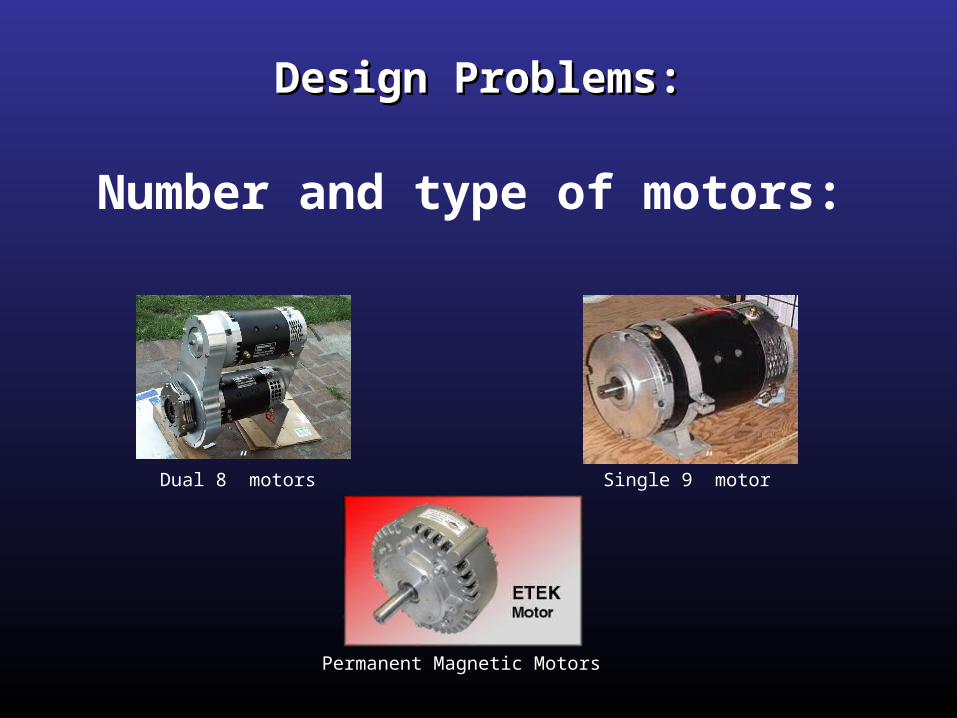
Dual 8” motors Single 9” motor
Permanent Magnetic Motors
Number and type of motors:
Design Problems:Design Problems:
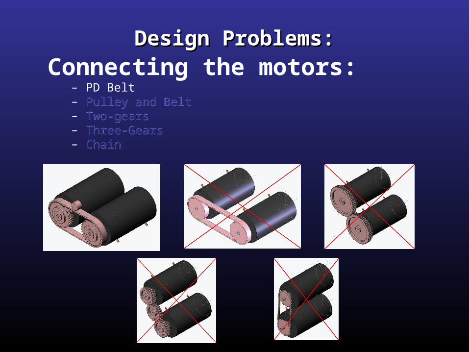
Design Problems:Design Problems:Connecting the motors:
– PD Belt– Pulley and BeltPulley and Belt– Two-gearsTwo-gears– Three-GearsThree-Gears– ChainChain
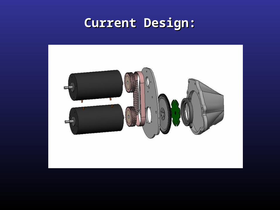
Current Design:Current Design:
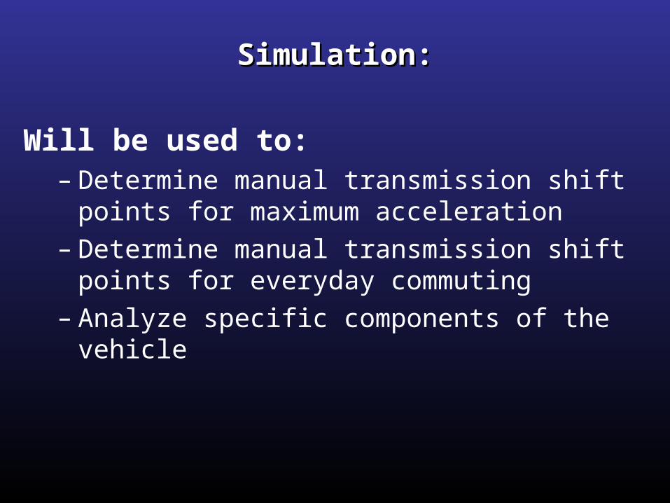
Simulation:Simulation:
Will be used to:– Determine manual transmission shift points for
maximum acceleration– Determine manual transmission shift points for
everyday commuting– Analyze specific components of the vehicle
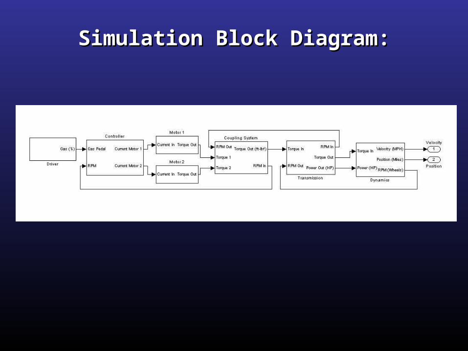
Simulation Block Diagram:Simulation Block Diagram:
Simulation Components:Simulation Components:
• Driver• Controller• Motors• Coupling System• Transmission• Car Dynamics

Driver:Driver:
Assumes pedal to the metal
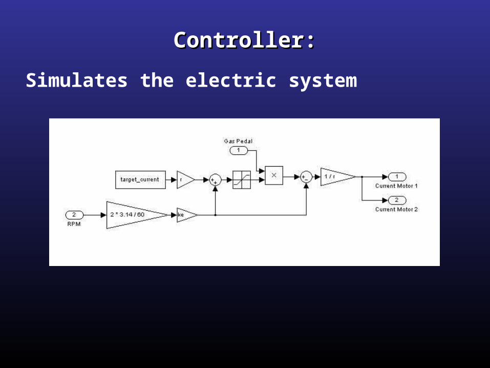
Controller:Controller:
Simulates the electric system
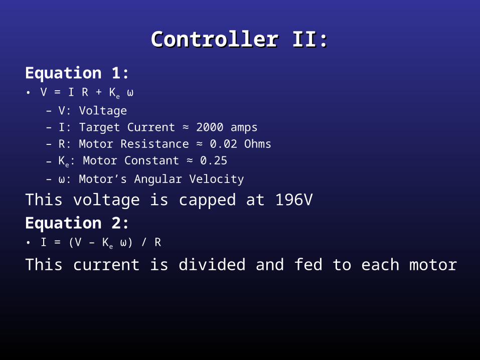
Controller II:Controller II:
Equation 1:• V = I R + Ke ω
– V: Voltage– I: Target Current ≈ 2000 amps– R: Motor Resistance ≈ 0.02 Ohms
– Ke: Motor Constant ≈ 0.25
– ω: Motor’s Angular Velocity
This voltage is capped at 196V
Equation 2:• I = (V – Ke ω) / R
This current is divided and fed to each motor
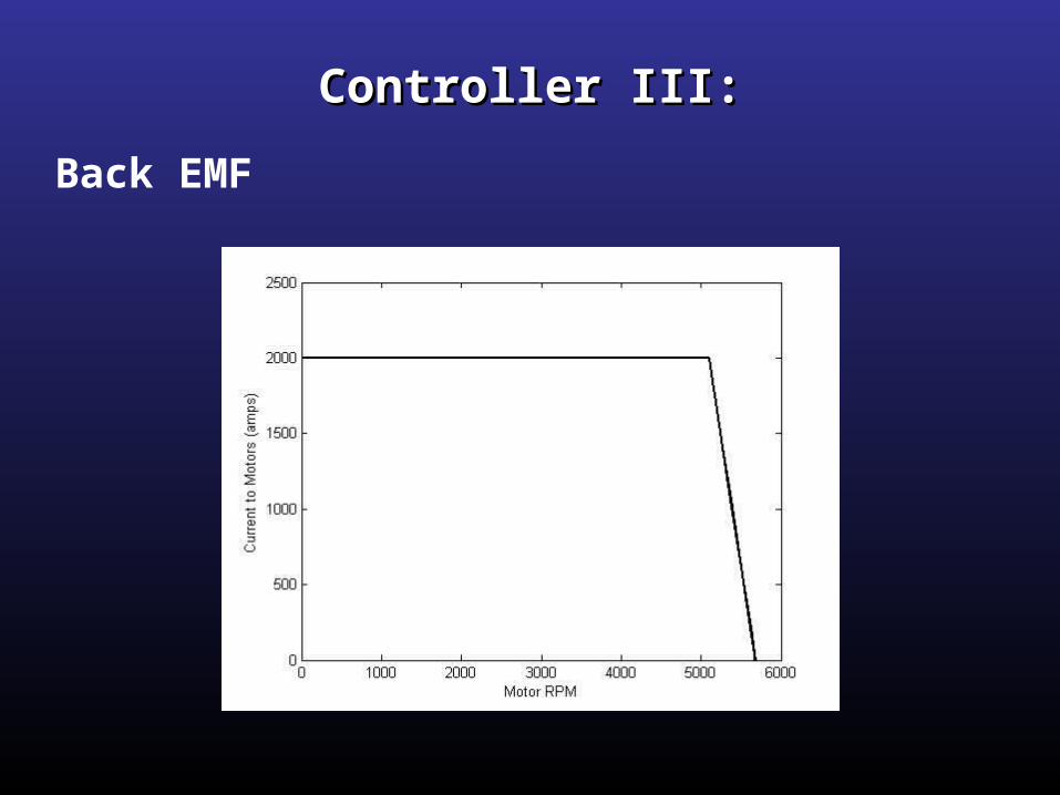
Controller III:Controller III:
Back EMF
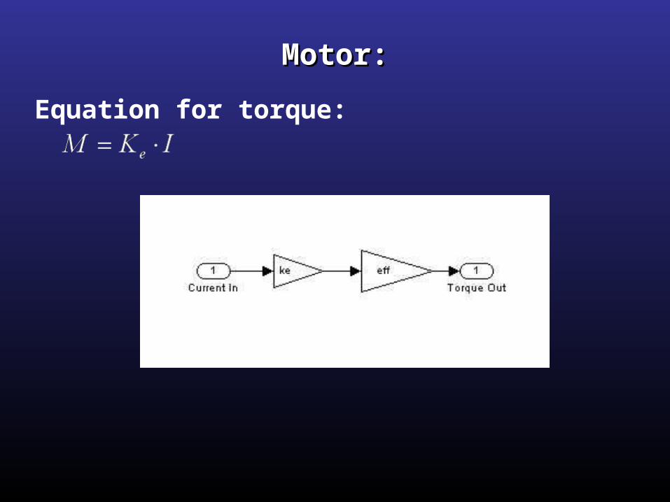
Motor:Motor:
Equation for torque:
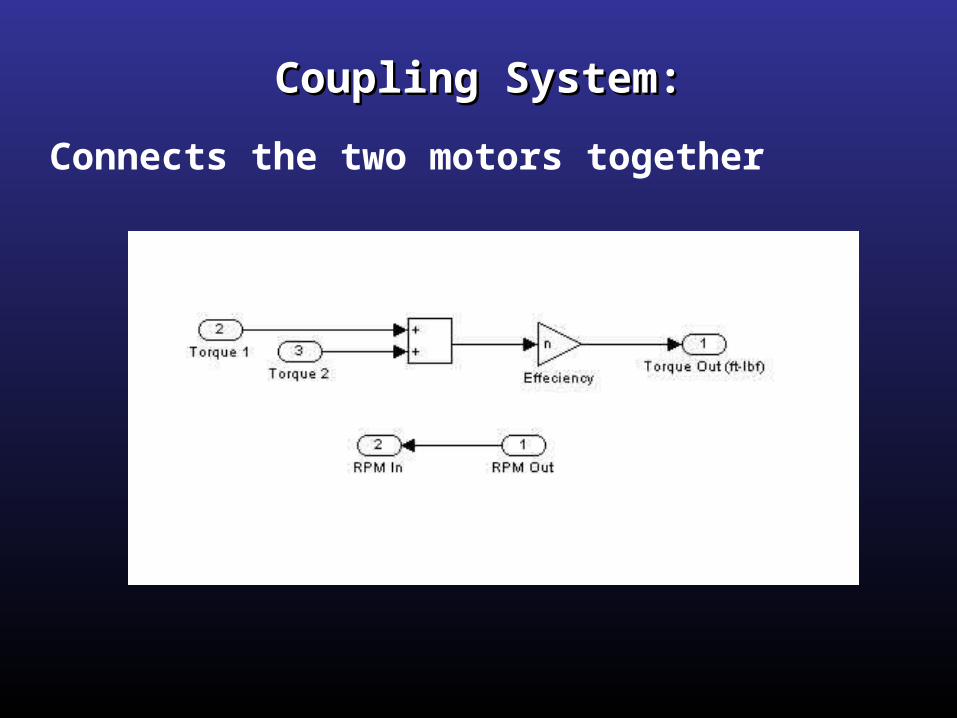
Coupling System:Coupling System:
Connects the two motors together
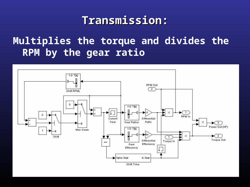
Transmission:Transmission:
Multiplies the torque and divides the RPM by the gear ratio
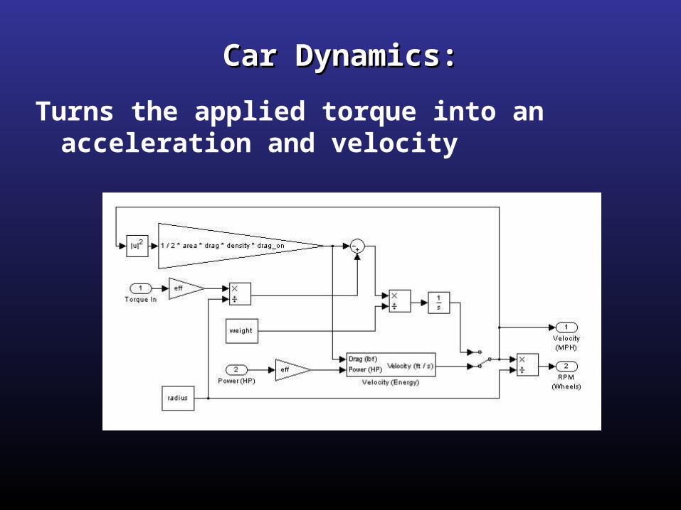
Car Dynamics:Car Dynamics:
Turns the applied torque into an acceleration and velocity
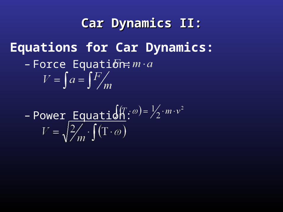
Car Dynamics II:Car Dynamics II:
Equations for Car Dynamics:– Force Equation:
– Power Equation:
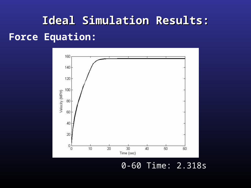
Ideal Simulation Results:Ideal Simulation Results:Force Equation:
0-60 Time: 2.318s
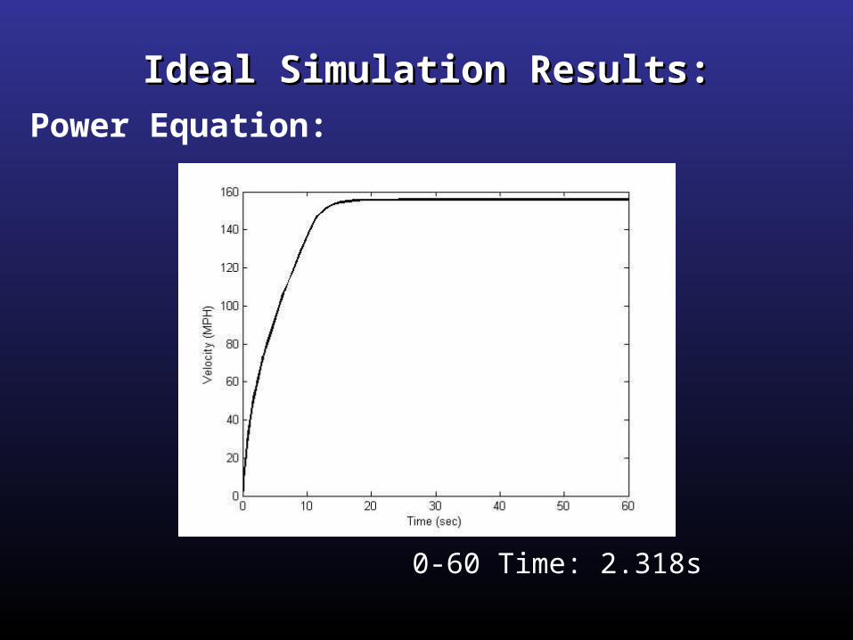
Ideal Simulation Results:Ideal Simulation Results:
0-60 Time: 2.318s
Power Equation:

More Realistic Simulation Results:More Realistic Simulation Results:Force Equation:
0-60 Time: 4.170s
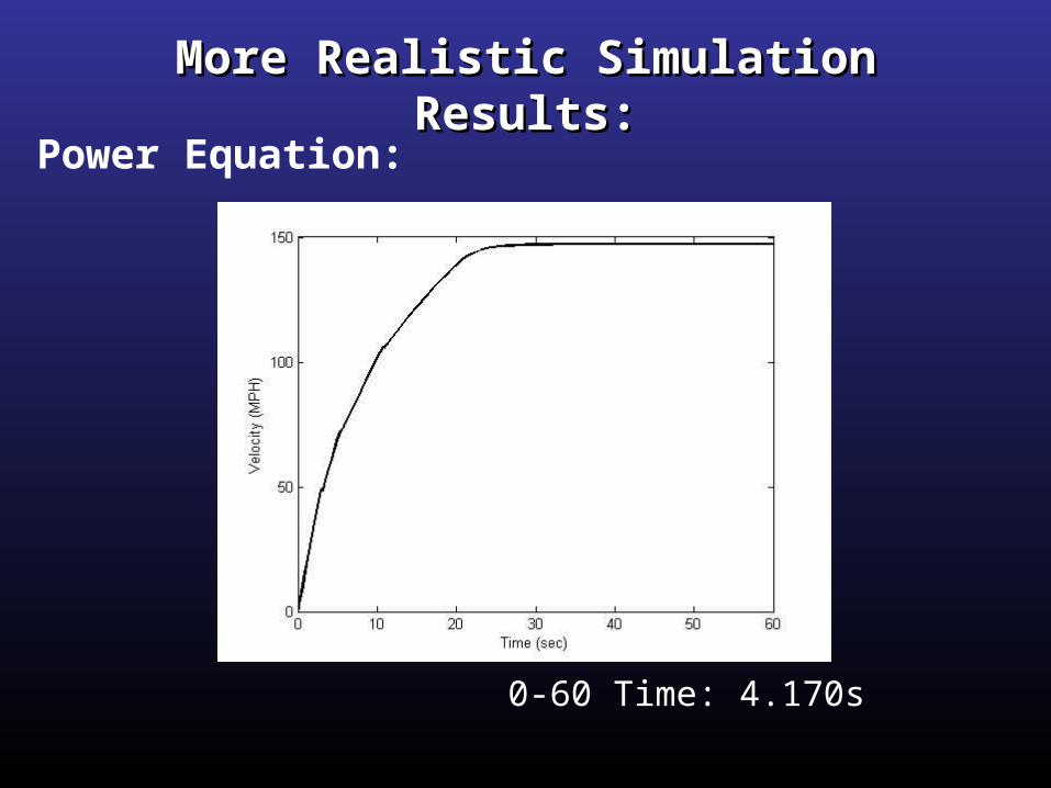
More Realistic Simulation Results:More Realistic Simulation Results:Power Equation:
0-60 Time: 4.170s
Future Addition:Future Addition:Tire SlippageTire Slippage
Two ideas of how to model tire slippage:– Realistic approach: If the torque is too high, the tires slip
– Ideal approach: The torque is capped before the tires can slip
Inaccuracies:Inaccuracies:
• Motor calculations• No tire slippage• Efficiencies • Drag constants• Modeling the driver

Questions?Questions?