Embed Size (px)
Citation preview

PERFORMANCE ANALYSIS OF METAL HYDRIDE-
BASED HYDROGEN STORAGE SYSTEM
NUR AIN AMIRAH BINTI RUSMAN
DISSERTATION SUBMITTED IN FULFILMENT OF
THE REQUIREMENTS FOR THE DEGREE OF MASTER
OF ENGINEERING SCIENCE
FACULTY OF ENGINEERING
UNIVERSITY OF MALAYA
KUALA LUMPUR
2018 Univers
ity of
Mala
ya

ii
UNIVERSITY OF MALAYA
ORIGINAL LITERARY WORK DECLARATION
Name of Candidate: (I.C/Passport No: )
Matric No:
Name of Degree:
Title of Project Paper/Research Report/Dissertation/Thesis (“this Work”):
Field of Study:
I do solemnly and sincerely declare that:
(1) I am the sole author/writer of this Work;
(2) This Work is original;
(3) Any use of any work in which copyright exists was done by way of fair dealing
and for permitted purposes and any excerpt or extract from, or reference to or
reproduction of any copyright work has been disclosed expressly and
sufficiently and the title of the Work and its authorship have been
acknowledged in this Work;
(4) I do not have any actual knowledge nor do I ought reasonably to know that the
making of this work constitutes an infringement of any copyright work;
(5) I hereby assign all and every rights in the copyright to this Work to the
University of Malaya (“UM”), who henceforth shall be owner of the copyright
in this Work and that any reproduction or use in any form or by any means
whatsoever is prohibited without the written consent of UM having been first
had and obtained;
(6) I am fully aware that if in the course of making this Work I have infringed any
copyright whether intentionally or otherwise, I may be subject to legal action
or any other action as may be determined by UM.
Candidate’s Signature Date:
Subscribed and solemnly declared before,
Witness’s Signature Date:
Name:
Designation:
Univers
ity of
Mala
ya

iii
PERFORMANCE ANALYSIS OF METAL HYDRIDE-BASED HYDROGEN
STORAGE SYSTEM
ABSTRACT
Energy is one of the basic requirements in our daily lives. The world’s energy demand
is continuously increasing over the years due to the ever-increasing growth in the human
population as well as economic development. At present, approximately 90% of energy
demand are fulfilled by fossil fuels. With the rising demands of energy throughout the
globe, it can be expected that the availability of fossil fuels is depleting at an alarming
rate since fossil fuels are non-renewable sources of energy. In addition, fossil fuels are
the main contributor of greenhouse gas emissions and therefore, they have a detrimental
impact on human health and environment in the long term. Hence, there is a critical need
to develop alternative sources of energy in replacement of fossil fuels. For that reason,
hydrogen fuels have gained much interest among researchers all over the world since they
are clean, non-toxic and renewable energy source. However, the greatest challenge in
using hydrogen fuels lies in the development of hydrogen storage systems, especially for
on-board applications. Current technologies used for hydrogen storage include high-
pressure compression at about 70 MPa, liquefaction at cryogenic temperature (20 K) and
absorption into solid state compounds. Among the three types of hydrogen storage
technologies, the storage of hydrogen in solid state compounds appears to be the most
feasible solution since it is a safer and more convenient. Because of that, hydrogen stored
in solid state as metal hydride has been studied for this project. In this project, a three-
dimensional dynamic simulation for metal hydride based hydrogen storage tank was
performed using Computational Software COMSOL 5.1a Multiphysics. The software is
used to simulate the charging process in the metal hydride container that is able to
represent the system’s behavior. The model consists of a system of partial differential
Univers
ity of
Mala
ya

iv
equations (PDE) describing three dimensional heat and mass transfer of hydrogen in a
porous matrix and has been implemented in a finite element program that allows obtaining
results on the charging variables at different studied scenarios. The model is validated
against published data and later the simulation result is compared with experimental data
to validate experimentally the numerical simulation. The effects of different parameters
such as porosity (ε), permeability (𝐾), metal thermal conductivity (𝑘𝑚), hydrogen
absorption constant on metal (c𝑎), activation energy (𝐸𝑎) and heat transfer coefficient
(ℎ𝑐𝑡 ) on the metal hydride behavior during hydrogen gas absorption are investigated. The
validation of the mathematical model is concluded to achieve a good agreement between
all the data while the simulation and experimental results show agreement with each other
having small deviation between 0.0~2.5%. Lastly, the sensitivity analysis indicated that
the effective thermal conductivity was the most sensitive parameters for this system while
other parameters such as porosity, permeability and heat transfer coefficient carried little
effect on the system.
Keywords: Energy, Hydrogen storage, Metal hydride, Absorption, COMSOL
Multiphysics
Univers
ity of
Mala
ya

v
ANALISI PRESTASI SISTEM PENYIMPANAN HIDROGEN BERASASKAN
HIDRIDA LOGAM
ABSTRAK
Tenaga adalah salah satu keperluan asas dalam kehidupan seharian manusia. Sejak
beberapa tahun kebelakangan ini, permintaan dunia terhadap tenaga terus meningkat
disebabkan oleh pertumbuhan masyarakat serta pembangunan ekonomi yang semakin
pesat. Pada masa ini, kira-kira 90% daripada permintaan terhadap tenaga dipenuhi oleh
bahan api fosil. Dengan permintaan tenaga yang semakin meningkat di seluruh dunia,
dijangkakan bahawa ketersediaan bahan api fosil akan semakin berkurang pada kadar
yang membimbangkan kerana bahan api fosil adalah sumber tenaga yang tidak boleh
diperbaharui. Selain itu, bahan api fosil adalah penyumbang utama pelepasan gas rumah
hijau yang membawa kesan yang buruk kepada kesihatan manusia dan alam sekitar untuk
jangka masa panjang. Oleh itu, terdapat keperluan kritikal untuk membangunkan sumber
tenaga alternatif untuk menggantikan bahan api fosil. Disebabkan itu, hidrogen sebagai
sumber bahan api telah mendapat perhatian di kalangan penyelidik di seluruh dunia
kerana ianya bersih, tidak toksik dan sejenis sumber tenaga yang boleh diperbaharui.
Walau bagaimanapun, cabaran yang paling besar dalam menggunakan bahan api
hidrogen terletak pada pembangunan sistem penyimpanan hidrogen, terutama untuk
aplikasi system pengangkutan. Teknologi semasa yang digunakan untuk penyimpanan
hidrogen sekarang adalah termasuk mampatan tekanan tinggi pada kira-kira 70 MPa,
pencairan pada suhu kriogenik (20 K) dan penyerapan ke dalam sebatian pepejal. Antara
tiga jenis teknologi penyimpanan hidrogen, penyimpanan hidrogen dalam keadaan
sebatian pepejal muncul sebagai penyelesaian yang paling boleh dilaksanakan kerana ia
adalah lebih selamat dan lebih mudah. Disebabkan itu, hidrogen yang disimpan dalam
keadaan pepejal sebagai hidrida logam telah dikaji dalam projek ini. Dalam projek ini,
simulasi dinamik tiga dimensi untuk tangki simpanan hidrogen berasaskan logam hidrida
Univers
ity of
Mala
ya

vi
telah dilaksanakan dengan menggunakan perisian pengiraan Multiphysics COMSOL
5.1a. Perisian ini digunakan untuk mensimulasikan proses penyerapan hidrogen dalam
logam hidrida yang mampu mewakili kelakuan sistem. Model ini merangkumi sistem
persamaan pembezaan separa (PDE) yang menggambarkan pemindahan haba dan jisim
hidrogen dalam tiga dimensi dalam matriks berliang. Model ini disahkan dengan data
yang pernah diterbitkan oleh penyilidik sebelum ini dan keputusan simulasi kemudian
dibandingkan dengan data eksperimen untuk mengesahkan simulasi berangka. Selepas
itu, kesan parameter yang berbeza seperti keliangan (ε), kebolehtelapan (𝐾),
kekonduksian terma logam (𝑘𝑚), pemalar hidrogen berterusan pada logam (c𝑎), tenaga
pengaktifan (𝐸𝑎) dan pekali pemindahan haba (ℎ𝑐𝑡) Semasa penyerapan gas hidrogen
disiasat. Selain itu, penyelidikan ini juga akan memberi tumpuan kepada pengoptimuman
parameter operasi untuk prestasi sistem hidrida logam. Pengesahan model matematik
disimpulkan untuk mencapai persetujuan yang baik di antara semua data sementara hasil
simulasi dan percubaan menunjukkan kesepakatan antara satu sama lain dengan sisihan
kecil antara 0.0 ~ 2.5%. Akhir sekali, analisis kepekaan menunjukkan bahawa
kekonduksian terma yang berkesan adalah parameter yang paling sensitif untuk sistem
ini sementara parameter lain seperti keliangan, kebolehtelapan dan pekali pemindahan
haba membawa sedikit kesan ke atas sistem.
Kata kunci: Tenaga, Peyimpanan hidrogen, Hidrida logam, Penyerapan, COMSOL
Multiphysics
Univers
ity of
Mala
ya

vii
ACKNOWLEDGEMENTS
First and foremost, I would like to acknowledge the assistance and guidance of my
supervisor, Associate Prof. Ir. Dr. Mahidzal Bin Dahari, who allowed me to work on his
project and helped guide me through my research. I want to thank him for his patience
with me and willingness to spend additional time helping me complete this thesis. I also
would like to express my gratitude to the University Malaya (UM) Hydrogen Fuel Cell
laboratory for giving me the opportunity to do the necessary research work while
providing me with all the necessary resources and elements. Lastly, I would like to thank
my family, especially my parents for their encouragements and my dear friends for their
active assistance.
Univers
ity of
Mala
ya

viii
TABLE OF CONTENTS
performance analysis of metal hydride-based hydrogen storage system ......................... iii
analisi prestasi sistem penyimpanan hidrogen berasaskan hidrida logam ........................ v
Acknowledgements ......................................................................................................... vii
Table of Contents ........................................................................................................... viii
List of Figures ................................................................................................................ xiii
List of Tables.................................................................................................................. xvi
List of Symbols and Abbreviations ............................................................................... xvii
CHAPTER 1: INTRODUCTION .................................................................................. 1
1.1 Energy ……………………………………………………………………………..1
1.2 Hydrogen as Clean Energy ...................................................................................... 2
1.3 Hydrogen Storage .................................................................................................... 4
1.3.1 Compressed Gas Hydrogen ........................................................................ 5
1.3.2 Cryogenic Liquid Storage........................................................................... 5
1.3.3 Physical Storage with High Surface Area Material (Adsorbed hydrogen) 6
1.3.4 Chemical Storage in Solid State Material (Metal Hydrides) ...................... 7
1.4 Hydrogen Storage Target ......................................................................................... 8
1.5 Problem Statement ................................................................................................... 9
1.6 Research Objectives............................................................................................... 10
1.7 Scopes 10
1.8 Thesis Outlines ...................................................................................................... 11
CHAPTER 2: LITERATURE REVIEW .................................................................... 13
2.1 Metal Hydrides ...................................................................................................... 13
2.2 Hydrides Material Review ..................................................................................... 14
Univers
ity of
Mala
ya

ix
2.2.1 Intermetallic Compound ........................................................................... 14
2.2.1.1 AB5- type alloys ........................................................................ 15
2.2.1.2 AB-type alloys ........................................................................... 16
2.2.1.3 AB2-type (Laves phase) alloys .................................................. 17
2.2.1.4 AB3-type alloys ......................................................................... 17
2.2.1.5 A2B-type alloys ......................................................................... 17
2.2.1.6 Solid solution alloys .................................................................. 18
2.2.2 Complex Hydrides .................................................................................... 18
2.2.2.1 Alanates ..................................................................................... 19
2.2.2.2 Borohydrides ............................................................................. 23
2.2.2.3 Nitrides ...................................................................................... 27
2.2.3 Chemical hydrides .................................................................................... 28
2.2.3.1 Ammonia Borane ...................................................................... 28
2.2.4 Magnesium-based Alloys ......................................................................... 29
2.3 Fundamentals of Metal/Hydrogen Interactions ..................................................... 30
2.3.1 Thermodynamics of Metal/Hydrogen Interactions .................................. 30
2.3.2 Kinetics of Metal Hydrides ...................................................................... 33
2.4 Metal Hydrides Modelling Review ....................................................................... 37
2.4.1 One Dimensional Approach: Model Limitations ..................................... 37
2.4.2 Two and Three-Dimensional Models ....................................................... 40
CHAPTER 3: METHODOLOGY ............................................................................... 43
3.1 Introduction............................................................................................................ 43
3.2 Description of Dynamic Model ............................................................................. 44
3.2.1 Model Assumption ................................................................................... 45
3.2.2 Governing Equations ................................................................................ 45
3.2.2.1 Mass conservation ..................................................................... 46
Univers
ity of
Mala
ya

x
3.2.2.2 Momentum conservation ........................................................... 47
3.2.2.3 Energy conservation .................................................................. 47
3.2.3 Initial Conditions ...................................................................................... 48
3.2.4 Boundary Conditions ................................................................................ 49
3.2.5 Implementation of System into COMSOL Multiphysics ......................... 49
3.2.5.1 Physics Mode ............................................................................ 49
3.3 Validation of Mathematical Model ........................................................................ 51
3.3.1 Overview of the Model ............................................................................. 51
3.3.1.1 Geometry ................................................................................... 52
3.3.1.2 Material ..................................................................................... 52
3.3.1.3 Parameters used in Simulation .................................................. 53
3.4 Validation of Actual Simulation ............................................................................ 53
3.4.1 Overview of the Model ............................................................................. 54
3.4.1.1 Geometry ................................................................................... 54
3.4.1.2 Material ..................................................................................... 55
3.4.1.3 Parameters used in Simulation .................................................. 56
3.4.1.4 Mesh Sensitivity Analysis ......................................................... 57
3.4.2 Experimental Set Up ................................................................................ 57
3.5 Sensitivity Analysis of Metal Properties ............................................................... 60
3.6 Optimization on Metal Hydrides System .............................................................. 61
CHAPTER 4: RESULT AND DISCUSSION ............................................................. 62
4.1 Introduction............................................................................................................ 62
4.2 Modelling Results .................................................................................................. 62
4.2.1 Pressure .................................................................................................... 62
4.2.2 Temperature .............................................................................................. 63
4.2.3 Metal Hydrides Density ............................................................................ 64
Univers
ity of
Mala
ya

xi
4.3 Validation of Mathematical Model ........................................................................ 65
4.3.1 Temperature Evolution ............................................................................. 65
4.3.2 Equilibrium Pressure as a Function of hydrogen/ metal (H/M) ............... 66
4.4 Actual Simulation .................................................................................................. 67
4.4.1 Mesh Sensitivity Analysis ........................................................................ 67
4.4.2 Actual Simulation Results ........................................................................ 71
4.4.2.1 Temperature .............................................................................. 71
4.4.2.2 Mass of Hydrogen Absorbed ..................................................... 74
4.5 Validation of Actual Simulation ............................................................................ 77
4.5.1 Temperature .............................................................................................. 77
4.5.2 Mass of Hydrogen Absorbed .................................................................... 78
4.6 Sensitivity Analysis ............................................................................................... 79
4.6.1 Porosity (ε) ............................................................................................... 80
4.6.2 Permeability .............................................................................................. 82
4.6.3 Thermal Conductivity (𝑘𝑚)....................................................................... 83
4.6.4 Hydrogen Absorption Constant on Metal (c𝑎) .......................................... 85
4.6.5 Activation Energy (𝐸𝑎) ............................................................................. 86
4.6.6 Heat Transfer Coefficient (ℎ) ................................................................... 88
4.7 Effect of operating condition ................................................................................. 89
4.7.1 Charging pressure ..................................................................................... 89
4.7.2 Bed Temperature ...................................................................................... 91
CHAPTER 5: CONCLUSION & RECOMMENDATION ....................................... 94
5.1 Conclusion ............................................................................................................. 94
5.2 Recommendation ................................................................................................... 96
References ....................................................................................................................... 97
Univers
ity of
Mala
ya

xii
List of Publications and Papers Presented .................................................................... 107
Univers
ity of
Mala
ya

xiii
LIST OF FIGURES
Figure 2.1: (a) Phase diagram showing the transformation from α-phase to β-phase for
metal hydride; (b) Van’t Hoff plot derived from isotherms for various temperatures
(Züttel, 2003)................................................................................................................... 31
Figure 2.2: Simplified one-dimensional potential energy curve (Züttel, 2003) .............. 34
Figure 3.1: Geometry of metal hydride tank in COMSOL ............................................. 52
Figure 3.2: Geometry of the actual metal hydride tank in COMSOL ............................. 55
Figure 3.3: Hydrogen test rig located at Hydrogen Fuel Cell laboratory of University of
Malaya (UM) ................................................................................................................... 58
Figure 3.4: Simple experimental set up diagram ............................................................ 58
Figure 3.5: MH-350 Metal Hydride Canisters ............................................................... 60
Figure 4.1: Relative gas pressure inside the canister over time. Point located r = 0 mm, z
= 30 mm .......................................................................................................................... 63
Figure 4.2: Temperature inside the canister over time. Point locate r = 25 mm, z = 30 mm
......................................................................................................................................... 64
Figure 4.3: Metal hydride density over time. Point located r=0, z=0 ............................. 65
Figure 4.4: (a) Temperature evolution profiles obtained by Wang et al. (2009); (b)
Temperature evolution profiles obtained in this project ................................................. 66
Figure 4.5: (a) The equilibrium pressure as a function of the H/M atomic ratio and
temperature for hydrogen absorption by Mellouli et al. (2010) (b) The equilibrium
pressure as a function of the H/M atomic ratio and temperature for hydrogen absorption
this project ....................................................................................................................... 66
Figure 4.6: The characteristics of each types of mesh (a) Extra coarse; (b) Coarser; (c)
Coarse; (d) Normal; (e) Fine; (f) Finer; (g) Extra fine .................................................... 68
Figure 4.7: Density of metal hydrides bed for different types of mesh size at point r = 0
mm, z = 150 mm ............................................................................................................. 69
Figure 4.8: Temperature of metal hydrides canister for different types of mesh size at
point r = 0 mm, z = 150 mm ........................................................................................... 70
Figure 4.9: Temperature of metal hydride canister over time. Point located r = 0 mm, z =
322 mm ........................................................................................................................... 72
Univers
ity of
Mala
ya

xiv
Figure 4.10: Temperature profiles in half of a cross-section of the hydrogen storage
canister at (a) 0 s; (b) 100 s; (c) 200 s; (d) 300 s; (e) 400 s; (f) 500 s and (g) 600 s ....... 74
Figure 4.11: Mass of hydrogen gas absorbed over time. Point located at r = 0 mm, z = 150
mm .................................................................................................................................. 75
Figure 4.12: Density distribution in half of a cross-section of the hydrogen storage vessel
at (a) 0 s, (b) 100 s, (c) 200 s, (d) 300 s, (e) 400 s, (f) 500 s and (g)600 s ...................... 76
Figure 4.13: Temperature comparison between simulation and experimental data at point
r = 0 mm, z = 322 mm ..................................................................................................... 77
Figure 4.14: Comparison of hydrogen mass absorbed between simulation and
experimental data at point r = 0 mm, z = 150 mm .......................................................... 79
Figure 4.15: Density of metal hydride over time at different porosity values. Point located
at r = 0 mm, z = 150 mm ................................................................................................. 81
Figure 4.16: Temperature of metal hydride canister over time at different porosity values.
Point located r = 33 mm, z = 150 mm ............................................................................. 82
Figure 4.17: Density of metal hydride over time at different permeability values. Point
located at r = 0 mm, z = 150 mm .................................................................................... 83
Figure 4.18: Temperature of metal hydride canister over time at different permeability
values. Point located r = 33 mm, z = 150 mm ................................................................ 83
Figure 4.19: Density of metal hydride over time at different thermal conductivity values.
Point located at r = 0 mm, z = 150 mm ........................................................................... 85
Figure 4.20: Temperature of metal hydride canister over time at different thermal
conductivity values. Point located r = 33 mm, z = 150 mm ........................................... 85
Figure 4.21: Density of metal hydride over time at absorption rate constant values. Point
located at r = 0 mm, z = 150 mm .................................................................................... 86
Figure 4.22: Temperature of metal hydride canister over time at different absorption rate
constant values. Point located r = 33 mm, z = 150 mm .................................................. 86
Figure 4.23: Density of metal hydride over time at different activation energy values.
Point located at r = 0 mm, z = 150 mm ........................................................................... 87
Figure 4.24: Temperature of metal hydride canister over time at different activation
energy values. Point located r = 33 mm, z = 150 mm ..................................................... 87
Figure 4.25: Density of metal hydride over time at different heat transfer coefficient
values. Point located at r = 0 mm, z = 150 mm ............................................................... 88
Univers
ity of
Mala
ya

xv
Figure 4.26: Temperature of metal hydride canister over time at different heat transfer
coefficient values. Point located r = 33 mm, z = 150 mm .............................................. 89
Figure 4.27: Figure 4.27: Density of metal hydride over time at different charging
pressure values. Point located at r = 0 mm, z = 150 mm ................................................ 90
Figure 4.28: Temperature of metal hydride canister over time at different charging
pressure values. Point located r = 33 mm, z = 150 mm .................................................. 90
Figure 4.29: Density of metal hydride over time at different bed temperature values. Point
located at r = 0 mm, z = 150 mm .................................................................................... 92
Figure 4.30: Temperature of metal hydride canister over time at different bed temperature
values. Point located r = 33 mm, z = 150 mm ................................................................ 92
Univers
ity of
Mala
ya

xvi
LIST OF TABLES
Table 1.1: General characteristics of basic hydrogen storage methods ............................ 4
Table 1.2: Summary of targets for hydrogen storage systems set by DOE ...................... 8
Table 3.1: Table of physics mode and implementation of governed equations .............. 51
Table 3.2: List of parameters used in simulation for 𝐋𝐚𝐍𝐢𝟓 system .............................. 53
Table 3.3: List of properties of Ti0.99Zr0.01V0.43Fe0.09Cr0.05Mn1.5 alloy............................ 56
Table 3.4: List of parameters and operating conditions used in the simulation .............. 56
Table 3.5: List of parameters used in the parametric studies for each parameter. .......... 61
Table 3.6: Operating value used in the optimization studies for charging pressure and
temperature ...................................................................................................................... 61
Table 4.1: Density values of metal hydrides bed for different types of mesh size at point
r = 0 mm, z = 150 mm ..................................................................................................... 69
Table 4.2: Temperature values of metal hydrides canister for different types of mesh size
at point r = 0 mm, z = 150 mm........................................................................................ 70
Table 4.3: Summarization of total mesh size and solution time of each mesh type ....... 71
Table 4.4: Temperature comparison between simulation and experimental data at point r
= 0 mm, z = 322 mm ....................................................................................................... 78
Table 4.5: Comparison of hydrogen mass absorbed between simulation and experimental
data at point r = 0 mm, z = 150 mm ................................................................................ 79
Univers
ity of
Mala
ya

xvii
LIST OF SYMBOLS AND ABBREVIATIONS
General symbols
𝑐 Heat capacity J/kg. K
𝐶𝑎 Absorption constant s−1
𝑑 Diameter m
𝐸 Energy J/mol
𝐸𝑎 Activation energy J/mol
�⃗⃗� Gravity ms−2
ℎ Heat Transfer Coefficient W/m2. K
𝑘 Thermal conductivity W/m.K
𝐾 Permeability m2
𝑚 Mass g
𝑀 Molar weight g/mol
�⃗⃗� Normal vector unit -
𝑃 Pressure 𝑏𝑎𝑟/ 𝑃𝑎
Q Heat J
𝑅 Gas constant J/mol. K
𝑆 Source Term −
𝑡 Time 𝑠
𝑇 Temperature K/ ℃
�⃗⃗� Velocity ms−1
Greek letters
∆𝐻 Reaction enthalpy J/mol
Univers
ity of
Mala
ya

xviii
∆𝑆 Reaction entropy J/mol. K
𝜀 Porosity −
𝜇 Hydrogen dynamic viscosity Pa. s
𝜋 Pie −
𝜌 Density kg/m3
Sub-/ Superscripts
0 Initial
𝑎𝑚𝑏 Ambient
𝑎𝑡𝑚 Atmosphere
𝐶 Chemisorbed
𝐷 Dissociation
𝑒 Effective
𝑒𝑞 Equilibrium
𝑒𝑥𝑡 Exterior
𝑔 Gas
ℎ Hydrogen
𝑖𝑛 Inlet
𝑚 Metal
𝑝 Particle
𝑃 Physisorbed
𝑟𝑒𝑓 Reference
𝑠𝑎𝑡 Saturated
𝑇 Energy (source term)
Univers
ity of
Mala
ya

xix
Abbreviations
DAE Differential Algebraic Equation
DOE Department of Energy
MH Metal Hydride
ODE Ordinary Differential Equation
SEM Scanning Electron Microscope
UM University Malaya
Univers
ity of
Mala
ya

1
CHAPTER 1: INTRODUCTION
1.1 Energy
The world energy demand is increasing with the increase in human population and
pursuit of higher standards of living (Baladincz & Hancsók, 2015). To meet the human
needs for energy, a large amount of fuel is widely utilized from various fossil resources
(Ashraful et al., 2014). This results in the risen of all types of fossil fuels production in
the late 20th and early 21st centuries (Kontorovich et al., 2014). Fossil fuels, mainly
petroleum-based liquid fuels, natural gas and coal, are important for global energy
demands, accounting for more than 80% of the world global primary energy consumption
(Mohr et al., 2015). Therefore, human society, with its expansion and high technological
development, is very dependent on petroleum fuel for its activities (Banković-Ilić et al.,
2014).
Unfortunately, the production and utilization of fossil fuel cause environmental
problems, for example, rising carbon dioxide levels in the atmosphere. Carbon dioxide is
the main greenhouse gas, and about 75% of the carbon dioxide emission is due to the
burning of fossil fuels. Emissions of carbon dioxide have been the topic of worldwide
debate in regard to the sustainability of energy and stability of the global climate (Ball &
Wietschel, 2009). During the next decades, the most challenging environmental tasks is
to reduce the impacts of global warming from the burning of fossil fuels (Hoel &
Kverndokk, 1996).
It is undeniable that combustion of fossil fuels has caused serious detrimental
environmental consequences. Due to their non-renewable nature, fossil fuels are projected
to be exhausted in the near future as it takes millions of years to form with limited reserves
and high prices. This situation has worsened with the rapid rise in energy demand with
significant worldwide population growth (Ashraful et al., 2014). Since fossil fuels are a
Univers
ity of
Mala
ya

2
limited resource, it can be predicted that by 2020–2030 mankind has to face the challenges
arising from the sustainability of conventional oil production.
In conclusion, the world is moving toward an energy crisis with the depletion of
conventional, non-renewable, fossil- based fuel, which forcing the human society to look
for other alternatives. The depleting of fossil fuel based energy has triggered research and
development works on alternative source for reliable, environmentally friendly and yet
economically feasible renewable energy (Issariyakul & Dalai, 2014).
1.2 Hydrogen as Clean Energy
With the existed energy crisis, clean energy technologies, such as biofuels, wind, solar,
hybrid electric, geothermal, and hydrogen has grown worldwide interest in recent years
(Garland et al., 2012). However, for this type of energy sources, a safe and clean energy
carrier is needed to ensure an environmentally friendly energy system. With the
development of the proton exchange membrane (PEM) fuel cell, hydrogen has been seen
as a potential solution for this crisis. Proton exchange membrane (PEM) fuel cell which
is fuelled by hydrogen and oxygen, is harmless to the environment as it produces only
water (Mao et al., 2012).
Assuredly, hydrogen is regarded as a promising solution for the current energy crisis
(Orhan & Babu, 2015) and has attracted worldwide attention as a safe and clean energy
carrier (Nath et al., 2015), (Klindtworth et al., 2018). Across the world, interest in
hydrogen has been growing as a potential fuel for transportation and medium for energy
storage (Ehret & Bonhoff, 2015). Such interest is primarily due to the potency of
hydrogen for replacing fossil fuels in the transport sector and at the fact that hydrogen
can be stored over for a long period of time (López González et al., 2015).
Univers
ity of
Mala
ya

3
Most of world hydrogen productions are mainly from the non-renewable energy
sources (S. Sharma & Ghoshal, 2015). However, hydrogen as energy carrier can be
produced from both renewable and non-renewable sources. Unlike petroleum, which is
non-renewable and produce pollutants, hydrogen can be generated from renewable
energy sources and is free from pollutants, as its only produces water (Orhan & Babu,
2015). For long term sustainable hydrogen production, hydrogen can be produced from
various renewable primary energy sources such as solar, wind, biogases, industrial waste
streams and nuclear power (Brouwer, 2010). In short, hydrogen from renewable sources
is regarded as a potential replacement for common fossil energy carriers (Tietze &
Stolten, 2015).
Hydrogen has unique features that make it a promising secondary energy carrier. This
includes the fact that it can be generated from and converted into electrical energy and is
environmentally friendly since its production, storage and transportation do not produce
any pollutants (Sherif et al., 2005). Hydrogen is very volatile and, possibly, it is very
quickly dissipated in the surroundings. It is also practically impossible to make hydrogen
explode except for a much reduced spaces (Cipriani et al., 2014). Besides, hydrogen is
the lightest element in the periodic table of element, not toxic, nor corrosive and the most
abundant element in the universe (Winter, 2009).
Hence, it is hopeful to promote a '' hydrogen economy '', where hydrogen can be
expected to substitute oil and natural gas in many applications, including transportation
and heating (Shinnar, 2003). According to the approach of ‘hydrogen economy’,
hydrogen can become the main secondary energy carrier at the end of the 21st century and
will gradually replace fossil fuels (Marchenko & Solomin, 2015). The role of hydrogen
in sustainable energy economy which requires full attention in terms of policy studies,
Univers
ity of
Mala
ya

4
researches and developments, as well as commercialization of the potential technologies
(Andrews & Shabani, 2012).
Unfortunately, due to its gaseous property of low density, storage of hydrogen remains
a big challenge (Mori & Hirose, 2009). Hydrogen storage system is regarded as one of
the greatest obstacles, particularly for mobile application which must be resolved before
an economically and technically viable hydrogen fuel system can be produced. Without
an efficient storage system, ‘hydrogen economy’ will be a challenging task to be
accomplished (Ball & Wietschel, 2009).
1.3 Hydrogen Storage
Hydrogen storage is often considered as the most crucial issue in order to obtain a
‘hydrogen economy’ free of environmental pollution and fossil fuel (Aceves et al., 2013).
In order to meet the vehicle restrictive volume constraints, further compressing of the
gaseous fuel is required for the hydrogen storage system. At the same time, the storage
system must not badly affect the performance, design, and utility of the vehicle. At
present, several methods are being considered to store hydrogen, e.g., high-pressure gas
compression, cryogenic liquefaction, physically adsorbing porous materials and chemical
solid storage materials (Paggiaro et al., 2010), (Zheng et al., 2012). Four basic methods
that are used for hydrogen storage are being discussed in this chapter. General
characteristics of the basic hydrogen storage methods are given in Table 1.1 (Demirbas,
2007).
Table 1.1: General characteristics of basic hydrogen storage methods
Storage Method Pressure
(bar)
Temperature
(K)
Max capacity
(wt. %)
Compressed Gas Hydrogen 800 298 13
Cryogenic Liquid Hydrogen 1 21 100
Physically Adsorbed Hydrogen 70 65 14
Chemical Storage (Metal Hydride) 1 298-500 2-18
Univers
ity of
Mala
ya
5
1.3.1 Compressed Gas Hydrogen
Hydrogen act as a gas at room temperature and atmospheric pressure so it can be
compressed at high pressure, typically 350-700 bars, in a vessel capable of high pressure
(Hua et al., 2011). One of the advantages of hydrogen compression is that it provides fast
transfer rates during refuelling and discharging process (Maus et al., 2008). Besides, the
compressed hydrogen gas can be stored at an ambient temperature, thus avoiding costly
thermal insulation (Ananthachar & Duffy, 2005). At present, compressed gas cylinder is
the most commonly used hydrogen storage methods on vehicles (Züttel, 2003).
However, there are several issues with the current compressed hydrogen gas system.
Apparently, the overall efficiency of this method is reduced as there are large energy
losses during the compression of hydrogen. For instance, for compression to 800 bars, the
energy loss is usually in the order of 12-16% (Westerwaal & Haije, 2008). Besides,
compressed hydrogen storage system has relatively low volumetric density compared to
other methods and stores the substantial mechanical compressive energy (∼ 0.6kWh/kg
H2), which can be abruptly discharged in case of vessel breakdown (Aceves et al., 2006;
Paggiaro et al., 2010).
1.3.2 Cryogenic Liquid Storage
In a highly insulated vacuum vessel, hydrogen can be stored as liquid at very low
temperatures (20K) through liquefaction (Ananthachar & Duffy, 2005). Liquefaction of
hydrogen allows higher storage density and represent the ideal solution when a huge scale
of hydrogen storage and long distance transportation is required (Trevisani et al., 2007).
Other benefits of liquid hydrogen is it has high energy mass ratio which is three times
that of gasoline and high volumetric density at low pressure, which allows light, compact
and safe vehicular storage at considerably low cost (Aceves et al., 2013).
Univers
ity of
Mala
ya

6
The liquid hydrogen technology has grown significantly in recent years, allowing fast
(3 min) refuelling without any losses of evaporation and with very low rate of heat transfer
from the environment to the storage vessels (~ 1W in H2 tank 5 kg). However, even at
this very low rate of heat transfer, evaporation losses remain a problem, as hydrogen must
be released from a full container after 3-5 days of inactivity (Aceves et al., 2006). The
storage vessel usually suffers liquid hydrogen losses due to cryogen boil-off caused by
heat flow into the vessel from the higher surrounding temperature (Ho & Rahman, 2008).
Another disadvantage of liquid hydrogen storage is that it requires huge amounts of
energy for the liquefaction process (up to 40% of the lower heating value) which reduces
the overall efficiency of the system (Wolf, 2002). Therefore, cryogenic liquid hydrogen
storage method is limited only to applications where the hydrogen cost is disregarded and
the hydrogen gas is for short period usage (Schlapbach & Züttel, 2001).
1.3.3 Physical Storage with High Surface Area Material (Adsorbed hydrogen)
Another possible method to store hydrogen is by physically adsorbing molecular
hydrogen on material with a high surface area (Ross, 2006). The most popular material
for physical hydrogen storage are of carbonaceous nature, especially activated carbon
and carbon nanotubes (Georgakis et al., 2007). Physical storage with porous material
offers another alternative for safe hydrogen storage with high thermodynamic energy
efficiency and considerably lower storage pressure (S. J. Yang et al., 2012). For
physically adsorbing method, material with high specific surface area and slit pore nano-
structure is preferred as the main mechanism of hydrogen uptake is the monolayer
adsorption (Zhou et al., 2006).
Although this storage method has considerable advantages compared to other
conventional methods, effective storage of hydrogen is challenging because of its
extremely low density (Ho & Rahman, 2008). In fact, compared to conventional storage
Univers
ity of
Mala
ya

7
methods such liquid and gas storage, physically adsorbing porous material is heavier due
to the weight of the storage material. Other drawback of physical storage is that the
adsorption mechanism rely on van der Waals interactions, which are intrinsically low-
energy (S. J. Yang et al., 2012). Because of the weak van der Waals interaction,
significant adsorption can only be observed at low temperature, which is less than 273 K
(Züttel, 2003).
1.3.4 Chemical Storage in Solid State Material (Metal Hydrides)
Hydrogen can be chemically stored in solid material by incorporation into the crystal
structure of the storage material itself. Certain materials such as metals and alloys have
the ability to absorb hydrogen under moderate pressure (<1000psia) at low temperatures,
forming reversible hydrogen compounds called metal hydrides. Hydrogen can be
discharged from metal hydrides material by reducing pressure and by applying heat to the
system (Blackman et al., 2006). In order to satisfy all the conditions need for practical
solid-state hydrogen storage system, the chemical adsorbing hydrogen materials should
have high volumetric density, fast kinetic and low thermodynamic.
It has been proven that metal hydride as solid-state hydrogen storage offers a number
of advantages over compressed hydrogen gas and cryogenic hydrogen liquid methods (P.
Wang & Kang, 2008). Some of the advantages are that metal hydrides are capable of
storing large amounts of hydrogen (high volumetric hydrogen storage densities) and they
are inherently safer compared to mechanical hydrogen storage methods (Hong & Song,
2013). Metal hydrides appear to be the safest method of storing hydrogen since metal
hydrides can be operated at relatively low temperatures and pressures typical of fuel cell
vehicles and the release of hydrogen from metal hydrides is an endothermic process (R.
K. Jain et al., 2007). Different materials that are used for chemical hydrogen storage will
be discussed in much more detail in Chapter 2.
Univers
ity of
Mala
ya
8
1.4 Hydrogen Storage Target
It is expected that the “hydrogen economy” will require two types of hydrogen storage
systems, for stationary and mobile applications, including transportation. Each system
has its own constraints and requirements; however it is evident that mobile applications
are far more demanding (Agrawal et al., 2005). The on-board hydrogen system required
light, compact, safe and affordable containment and should meet the target set by the
United States Department of Energy (US DOE) for hydrogen powered vehicles in order
to compete with other commercialized vehicles in the market. The use of the targets for
hydrogen storage system set by the US DOE is to guide researchers and developers by
specifying system operating conditions in order to develop commercially practical
hydrogen storage systems.
Research is still ongoing to synthesize metal hydrides materials which will fulfil the
targets for hydrogen storage systems set by the US DOE for on-board vehicular
applications (Sai Raman et al., 2002). The reader may refer to the Reference (Srinivasa
Murthy & Anil Kumar, 2014) for a detailed treatment on the targets set by the US DOE
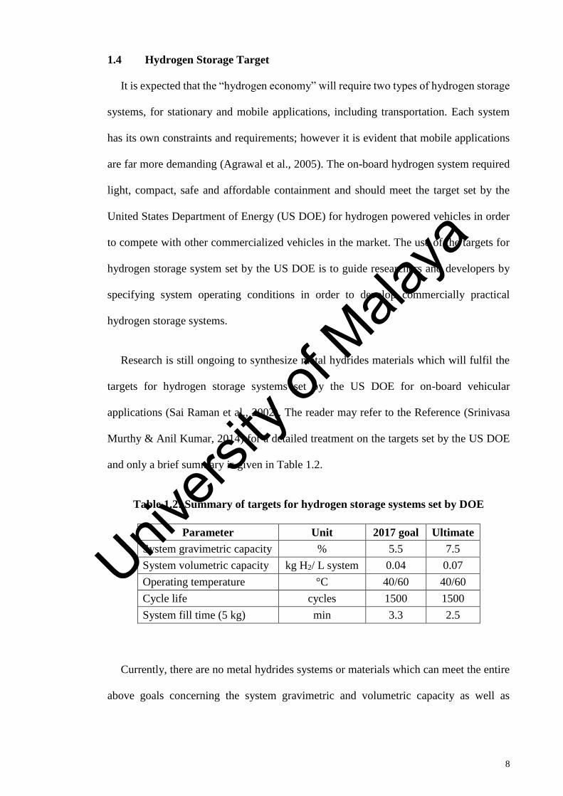
and only a brief summary is given in Table 1.2.
Table 1.2: Summary of targets for hydrogen storage systems set by DOE
Parameter Unit 2017 goal Ultimate
System gravimetric capacity % 5.5 7.5
System volumetric capacity kg H2/ L system 0.04 0.07
Operating temperature °C 40/60 40/60
Cycle life cycles 1500 1500
System fill time (5 kg) min 3.3 2.5
Currently, there are no metal hydrides systems or materials which can meet the entire
above goals concerning the system gravimetric and volumetric capacity as well as
Univers
ity of
Mala
ya

9
reaction kinetics and thermodynamics for practical on-board hydrogen storage systems
for mobile applications.
1.5 Problem Statement
Although there has been considerable research activities on the development of
potential metal hydrides materials, there are still no materials which can fulfil all of the
targets for hydrogen storage systems set by the US DOE, particularly for on-board
vehicular applications. To date, most of the hydrogen storage alloys can effectively store
about 1wt% to 3wt% of hydrogen only, which are insufficient for on-board vehicular
applications.
Besides, there are still a number of issues associated with the metal hydrides system
for hydrogen storage, i.e. slow reaction kinetics, low reversibility and high
dehydrogenation temperatures (Ma et al., 2013). Much effort is being made to synthesize
metal hydrides materials with low thermodynamics, fast reaction kinetics and high
gravimetric hydrogen storage capacities (Principi et al., 2009). Although there is a lot of
pressure to find metal hydrides materials that can meet or indeed exceed, the target set by
US DOE, one must realize the importance of taking into account both the material itself
and the final term use for application specific target.
Many experimental and theoretical studies have been conducted in the past which
focus on the heat and mass transfer aspects of metal hydrides systems for various
applications (Patil & Ram Gopal, 2013). It has been proved that the poor heat and mass
transfer aspects of metal hydrides beds are one of the major disadvantages of metal
hydrides for hydrogen storage systems. Therefore, a research project consists of
simulation analysis of metal hydrides properties for hydrogen storage is suggested. This
research project main purposed is to observe and analyse the effect of metal hydrides
Univers
ity of
Mala
ya

10
properties for hydrogen storage system during the absorption process especially in term
of mass and heat transfer.
1.6 Research Objectives
The main objective of this study is to observe and analyse the metal hydrides behaviour
for solid-state hydrogen storage system during the absorption process. The following sub-
objectives are defined within the frames of the main objective:
1. To simulate and validate a three-dimensional (3D) metal hydrides hydrogen storage
system with published and experimental data using COMSOL Multiphysics 5.1
software.
2. To validate the three-dimensional model with published data and simulation result
with experimental data.
3. To perform a sensitivity analysis on different metal hydrides properties in order to
determine their influence on the absorption process.
4. To perform an optimization study on the effect of operating parameter on metal
hydrides system.
1.7 Scopes
The scopes of this research are mainly focused on the analysis of metal hydrides bed
behaviour for solid-state hydrogen storage system during the hydrogen absorption process
and the effect of different metal hydrides properties on the performance of metal hydrides
system in terms of heat and mass transfer aspects as stated in the objectives. In order to
achieve the objectives stated in Section 1.5, the following activities are carried out.
1. A thorough literature review of current developments of different types of metal
hydrides material for solid-state hydrogen storage system is summarized.
2. Three-dimensional (3D) metal hydrides hydrogen storage system using COMSOL
Multiphysics 5.1 software is conducted to analyze the hydrogen absorption process
Univers
ity of
Mala
ya

11
numerically in order to understand how the absorption process works. The three-
dimensional model later is validated against published data while the simulation
results are compared with experimental data collected from the Hydrogen Fuel Cell
laboratory.
3. Series of parametric studies by modifying preperties of material are performed to
investigate the effects and consequences of different material properties on the metal
hydride based hydrogen storage system. The properties studied are porosity (ε),
permeability (𝐾), metal thermal conductivity (𝑘𝑚), hydrogen absorption constant on
metal (c𝑎), activation energy (𝐸𝑎) and heat transfer coefficient (ℎ).
4. Optimization study has been performed in order to determine the optimum operating
condition such as charging pressure and bed temperature in terms of absorption
efficiency.
1.8 Thesis Outlines
This research consists of 5 chapters. The contents of each chapter are described briefly
below:
CHAPTER 1 is the introductory chapter, which gives a background of study and an
introduction of hydrogen and the main idea and project aim and research objectives are
presented as well.
CHAPTER 2 is the literature review and it shows the previous study of chemical
storage in solid state materials, thermodynamics and kinetics of metal hydrides as well as
the review on metal hydrides modelling.
CHAPTER 3 describes the research methodology. In this chapter the method of
conducting the research has been illustrated.
Univers
ity of
Mala
ya

12
CHAPTER 4 presents the experimental and simulation results with their respective
discussion as well.
CHAPTER 5 where the main conclusions and contributions of the project are
summarized and the aim of this chapter is to clarify the findings of this research and
suggestions for the future works.
Univers
ity of
Mala
ya

13
CHAPTER 2: LITERATURE REVIEW
2.1 Metal Hydrides
Materials such as metals and alloys can form metal hydrides by reacting with hydrogen
which leads hydrogen into a solid state storage system under moderate temperature and
pressure. Using metal hydride as hydrogen storage which requires absorption and
desorption step. Hydrogen can be released from metal hydrides either by an increase in
temperature or a decrease in external pressure (I. P. Jain et al., 2010). Generally, metals
and alloys can reversibly form metal hydrides reversibly according to the following
reaction:
𝑀 +𝑥
2𝐻2 ↔ 𝑀𝐻𝑥 (2.1)
Where M denotes the metal. Metal hydrides consist of metal atoms that include a host
lattice for hydrogen atoms. Metal and hydrogen normally create two different types of
hydrides, 𝛼-phase where only some hydrogen is absorbed and 𝛽-phase where hydrogen
is completely absorbed. Hydrogen stored in metal hydrides depends on different
parameters with some mechanistic steps. Different metals have different ability to release
hydrogen as the ability which depends on surface structure, morphology and purity
(Sakintuna et al., 2007).
Hydride formation is an exothermic reaction due to lower entropy of the hydride
compared to the hydrogen in metal and gaseous phases. Consequently the hydrogen
desorption reaction is endothermic, therefore heat is needed to discharge the hydrogen.
An optimum hydrogen-storage material, should possess the following properties; high
mass and volumetric capacity, low desorption temperature and pressure, low heat of
formation in order to minimize the energy required for hydrogen release, low heat
dissipation during the exothermic hydride formation, minimum energy loss during
Univers
ity of
Mala
ya

14
hydrogen absorption and desorption, fast kinetics, good reversibility and cycle ability,
low cost and high safety (George & Saxena, 2010).
At present, the main materials for metal hydrides are intermetallic compounds (AB5,
AB2, AB and A2B), which has a hydrogen storage capacity of 1.5, 2.0, 1.8 and 3.0 wt%,
respectively. Solid solution alloys are also available such as vanadium-based solid
solution alloys with body-centred cubic structures and Mg-based alloys, which have a
hydrogen storage capacity of approximately 2 and 5 wt% respectively. To date, most of
the hydrogen storage alloys can effectively store about 2 to 3 wt% of hydrogen, but this
is insufficient for on-board vehicular applications based on the targets set by the US DOE.
Metal hydrides composed of lightweight elements such lithium, boron, nitrogen,
magnesium and aluminium have shown great potential for use as hydrogen storage
materials (Wu et al., 2013). Complex hydrides are the only group of metal hydrides
having high volumetric and gravimetric hydrogen storage densities (Varin et al., 2006).
2.2 Hydrides Material Review
Owing to the considerable number of articles pertaining to hydrogen storage materials
available in the literature, it is deemed useful to highlight and summarize the various types
of metal hydrides materials for solid-state hydrogen storage applications. The
summarized storage materials comprise of intermetallic compounds (AB5, AB, AB2, A2B
and AB3-type alloys, as well as solid solution alloys), complex hydrides (alanates,
borohydrides and nitrides), chemical hydrides and Mg-based alloys. The characteristics,
advantages and disadvantages of each type of metal hydride are discussed.
2.2.1 Intermetallic Compound
Intermetallic compounds have gained prominence in recent years due to their
widespread use in the development of hydrogen-absorbing metal alloys (Gasiorowski et
al., 2004). The applications of intermetallic compounds are numerous, which include
Univers
ity of
Mala
ya

15
hydrogen storage systems, nickel metal hydride (NiMH) battery electrodes, hydrogen
purification systems, hydrogen sensors and catalysts, heat pumps, as well as cooling
systems (Falahati & Barz, 2013). Intermetallic compounds are attractive for the
development of metal hydrides since they are capable of absorbing large quantities of
hydrogen. Moreover, they are available in abundance and they come in a variety of
compositions. In general, hydrogen reacts with intermetallic compounds, producing
crystalline or amorphous solid solutions of hydrogen in the respective compounds or in
the hydrides formed (Palewski et al., 2005).
The resultant hydrides are called intermetallic hydrides. The common formula for
intermetallic hydrides is AmBnHx. The properties of the intermetallic compounds are
determined by the interaction between the interstitial hydrogen atoms and the metal atoms
and therefore, they are largely dependent on the crystal structure of the compounds. AB5
(CaCu5 structure), AB2 (Laves phase), AB (CsCl relative structure), A2B (AlB2 relative
structure) and vanadium-based solid solution alloys are among the important types of
intermetallic compounds (Pan et al., 2003). It has been shown that AB5, AB2 and A2B-
type alloys have excellent hydrogen absorbing properties (Okada et al., 2002).
2.2.1.1 AB5- type alloys
AB5-type intermetallic compounds composed of rare earth metals and d-metals have
gained much interest in the last decade because of their hydrogen storage capabilities
(Borzone et al., 2013). AB5-type intermetallic compounds with CaCu5 structures remain
the most promising compounds owing to their high hydrogen absorption/desorption
capacities, good cyclic abilities, low equilibrium pressures, fast kinetics and good
resistance to impurities. However, the gravimetric hydrogen storage capacity of the
intermetallic hydrides produced from these compounds is rather low, with a value less
Univers
ity of
Mala
ya
16
than 1.5 wt%, due to the limitations of the CaCu5-type hexagonal structures (Pan et al.,
2003).
LaNi5-based hydrides are example of AB5-type alloys that has been widely
investigated for use as potential hydrogen storage materials because of their fast kinetics
as well as their ability to store hydrogen reversibly at ambient conditions (V. K. Sharma
& Anil Kumar, 2014), (Prigent et al., 2012). Typical LaNi5-based hydrides can release
about 0.9 wt% of hydrogen at 100oC. The exact amount of hydrogen released can reach
up to 1.2 wt%, with a maximum theoretical value of 1.5 wt% for on-board vehicular
applications (Georgiadis et al., 2009). However, LaNi5-based hydrides are very costly and
they have low theoretical hydrogen storage capacities. Hence, there is a critical need to
develop other cost-effective materials with high hydrogen storage capacities (Zhu et al.,
2011).
2.2.1.2 AB-type alloys
AB-type alloys are among the desirable materials in the development of intermetallic
hydrides because of their light molar mass and high weight capacities. TiFe alloys with
cubic CsCl-type structures are the most well-known alloys of this class and they are
capable of absorbing hydrogen reversibly up to 1.9 wt% (Ćirić et al., 2012). TiFe alloys
are able to absorb and desorb hydrogen provided that the conditions are favourable. These
conditions include fast absorption/desorption kinetics and high hydrogen absorption
capability at a hydrogen atom-to-metal atom (H/M) ratio of 1 near ambient conditions
(Endo et al., 2013). The TiFe alloy produces TiFeH and TiFeH2 hydrides and more
importantly, it is inexpensive compared to the LaNi5 alloy (Principi et al., 2009), (Islam
et al., 2018). However, TiFe alloy suffers from poor absorption/desorption kinetics, low
hydrogen storage capacity (less than 2 wt%), high equilibrium pressure and complicated
activation procedure (Ćirić et al., 2012).
Univers
ity of
Mala
ya
17
2.2.1.3 AB2-type (Laves phase) alloys
In AB2-type alloys, A represents titanium (Ti) or zirconium (Zr), whereas B represents
a transition metal. AB2-type (Laves phase) alloys composed of rare earth metals and non-
magnetic metals appeared to be simpler intermetallic compounds compared to those
containing transition metals (Orgaz, 2001). However, the use of rare earth metal-based
hydrides is rather limited since rare earth metals are very costly. For this reason, several
attempts have been made to synthesize cost-effective intermetallic hydrides without the
need for rare earth metals (Maeda et al., 2013).
Unlike AB5-type alloys, AB2-type alloys are more capable of forming a new phase at
high pressures – however, this is negated by the fact that the properties of these alloys are
easily hampered by the presence of contaminants (Principi et al., 2009). Hence, the
surface reactions of the alloys need to be improved in order to overcome this problem.
This can be done by substituting certain elements in the alloys with other elements which
will increase the surface area and catalytic properties of the alloys (Young et al., 2013).
2.2.1.4 AB3-type alloys
AB3-type alloys (where A = La, Ce, Y) have been studied extensively as potential
hydrogen storage materials in recent years due to their interesting properties for
electrochemical applications (Denys et al., 2007). However, the hydrogen storage
capacity is rather low for AB3-type alloys. LaNi3 is an example of an AB3-type alloy
which reacts with hydrogen during the hydrogenation process to produce the amorphous
hydride, LaNi3H5 (Latroche & Percheron-Guégan, 2003).
2.2.1.5 A2B-type alloys
A2B alloys are composed of an alkali earth metal (A) and a transition metal (B). Ti2Ni
alloys have gained much attention from scientists and researchers among all A2B-type of
alloys because of their desirable structural, magnetic and hydrogen storage properties.
Univers
ity of
Mala
ya

18
The partial substitution of Ti with Zr in Ti2Ni alloys increases the hydrogen desorption
capacity and cyclic ability of the substituted alloys. The stability of the substituted alloys
also decreases compared to the parent alloys which results in lower crystalline
temperatures (Zhao et al., 2012).
2.2.1.6 Solid solution alloys
It has been reported in previous studies that vanadium-based solid solution alloys with
body-centred cubic (BCC) structures have high gravimetric hydrogen storage capacities
up to 4 wt%, low hydrogen absorption/desorption temperatures, fast diffusion rates and
rapid activation. However, these alloys are still considered to be unsatisfactory for
commercial on-board vehicular applications due to their poor initial activation and low
absorption capacities. A large number of studies have been conducted over the years in
order to improve the kinetic and electrochemical properties of vanadium-based solid
solution alloys by implementing methods such as element substitution, annealing
treatment and surface modification (Yanzhi Wang et al., 2009).
Ti-based alloys with BCC structures such as Ti-V-Cr, Ti-V-Mn and Ti-Cr-Mo alloys
have high hydrogen storage capacity of almost 2 wt% and fast hydrogenation kinetics
near ambient conditions (Okada et al., 2002), (Endo et al., 2013). Pickering et al. (2013)
discovered that Ti0.5V0.5Mn alloys have fast absorption/desorption kinetics and high
reversible hydrogen capacities up to 1.9 wt% at a temperature and pressure of 260 K and
35 MPa, indicating that these alloys are potential hydrogen-absorbing materials.
2.2.2 Complex Hydrides
Complex hydrides composed of light elements such as lithium (Li) and sodium (Na)
which have gained significance as hydrogen storage materials since conventional metal
hydrides are mostly composed of heavy elements in the Periodic Table of Elements.
Lightweight complex hydrides emerge as potential candidates for hydrogen storage
Univers
ity of
Mala
ya

19
applications due to their high hydrogen storage capacities, high hydrogen storage
densities, as well as mild dehydrogenation pressures and temperatures (S. Srinivasan et
al., 2008).
Even though complex hydrides have high energy densities, they are difficult to handle
safely and they may decompose into highly stable elements, which are very challenging
to refuel with hydrogen on board a motor vehicle (Ley et al., 2014). More importantly,
most of these complex hydrides do not fulfil the targets set by the US DOE since they
have high thermodynamic stability and slow kinetics during hydrogen cycling (Huang et
al., 2006). However, these problems can be compensated to a certain extent by
thermodynamic destabilization, which involves the addition of a new element into the
system by means of cation or anion substitution, or the addition of reactive hydride
composites. Nanoconfinement or the addition of catalysts can also be used for
thermodynamic destabilization (Albanese et al., 2013).
2.2.2.1 Alanates
Complex aluminium hydrides (also known as complex aluminohydrides or alanates)
are hydrogen storage materials in which the evolution of hydrogen takes place upon
contact with water (Schuth et al., 2004). Aluminium is a good hydride destabilizing
component and it has been studied extensively in the development of alkali metal and
alkaline earth metal-based complex hydrides (Kumar et al., 2013). Alkali metal and
alkaline earth metal-based complex aluminium hydrides, MAlH4 (where M = Na, Li, K),
have shown to be good potential candidates for hydrogen storage materials at mild
pressures and temperatures (S. S. Srinivasan et al., 2004).
These hydrides have been widely studied since they have high theoretical hydrogen
capacities up to 10.4 wt% (Iosub et al., 2009). Unlike conventional metal hydrides,
MAlH4 desorbs through chemical decomposition – a process which begins with melting
Univers
ity of
Mala
ya

20
of the hydride, followed by the formation of an intermediate tri-alkali metal,
hexahydroaluminate (M3AlH6) (Gross et al., 2002). The decomposition process takes
place in a three-step reaction, which is given by Equations (2.2), (2.3) and (2.4).
𝑀AlH4(s) → 𝑀AlH4(l) (2.2)
𝑀AlH4(1) →1
3𝑀3AlH6 +
2
3Al + H2 (2.3)
1
3𝑀3AlH6 → 𝑀H +
1
3Al +
1
2H2 (2.4)
The decomposition temperature of these complex hydrides can be reduced to room
temperature by using a suitable metal catalyst (Wiench et al., 2004). Much efforts have
been given to synthesize mixed alanate compounds which have good thermodynamic and
kinetic properties (Akbarzadeh et al., 2009).
Sodium alanates
Sodium aluminium hydrides or sodium aluminohydrides (more commonly known as
sodium alanates, NaAlH4) are metal hydrides that have high hydrogen storage capacities.
NaAlH4 appear to be viable hydrogen storage materials since they have high hydrogen
content up to 5.6%, as well as desirable operating pressures and temperatures. In addition,
NaAlH4 are inexpensive and easily acquired in bulk (Tang et al., 2007).
However, the main disadvantage of NaAlH4 is the decomposition process of the
hydrides which takes place in a two-step reaction, as represented by Equations (2.5) and
(2.6) (Mosher et al., 2007). In the first step, the NaAlH4 decomposes into an intermediate
compound (Na3AlH6) and metallic Al, and the evolution of hydrogen takes place in this
step. The evolution of hydrogen continues in the second step, whereby the Na3AlH6
decomposes to form NaH and metallic Al. The first and second reaction releases 3.70 and
1.85 wt% of hydrogen, respectively (Thomas et al., 2002).
Univers
ity of
Mala
ya

21
NaAlH4 ↔1
3Na3AlH6 +
2
3Al + H2 (2.5)
Na3AlH6 ↔ NaH + Al +3
2H2 (2.6)
Even though NaAlH4 offer a number of advantages over conventional metal hydrides,
these hydrides suffer from poor reversibility, severe dehydrogenation conditions
(temperature: 473–673 K; pressure: 10–40 MPa) and slow kinetics (Bogdanović et al.,
2009). Hence, the use of NaAlH4 for reversible on-board vehicular applications may
prove to be an insurmountable obstacle in attaining the targets set by the US DOE for
hydrogen storage systems. This necessitates the addition of a suitable catalyst in order to
achieve the desired performance during the absorption/desorption process (Eberle et al.,
2006).
Lithium alanates
Lithium aluminium hydrides or lithium aluminohydrides (more commonly known as
lithium alanates, LiAlH4) have been widely investigated for use as potential hydrogen
storage materials because of their high hydrogen capacities up to 10.6 wt% (Vittetoe et
al., 2009). Unlike NaAlH4, LiAlH4 decomposes into LiH and Al in a three-step reaction,
which is given by Equations (2.7), (2.8) and (2.9). However, it shall be noted that the
hydrogenation process takes place at very high pressures. In the first step, LiAlH4
decomposes into Li3AlH6, Al and H2 at temperatures above 413 K. For second step, the
Li3AlH6 dissociates further into LiH, Al and H2 at temperatures above 463 K. In the third
step, the final decomposition of LiAlH4 takes place at temperatures higher than 673 K,
and these temperatures are extremely high for on-board vehicular applications (Xiong et
al., 2007).
3LiAlH4 → Li3AlH6 + 2Al + 3H2 (2.7)
Univers
ity of
Mala
ya

22
Li3AlH6 → 3LiH + Al +3
2H2 (2.8)
3LiH + 3Al → 3LiAl +3
2H2 (2.9)
The first, second and third reaction releases approximately 5.3, 2.6 and 3.6 wt% of
hydrogen, respectively. However, the third reaction is generally not considered due to the
extremely high temperatures (Vittetoe et al., 2009). Even though LiAlH4 are kinetically
stable, they are very thermodynamically unstable for hydrogen storage since they
decompose easily below room temperature (Schuth et al., 2004), (Bogdanović et al.,
2009), (Barkhordarian et al., 2007). In addition, LiAlH4 cannot be dehydrogenated within
the range of practical pressures due to their poor thermodynamic properties (Akbarzadeh
et al., 2009). Therefore, LiAlH4 are not practical for on-board hydrogen storage
application.
Calcium alanates
Calcium aluminohydrides (more commonly known as calcium alanates, Ca(AlH4)2)
can be synthesized from alkaline earth hydrides and AlCl3 using a simple ball milling
process. However, this process leads to the formation of alkaline earth chloride as a by-
product, which is difficult to be removed from the hydrides (Schuth et al., 2004).
Alternatively, Ca(AlH4)2 can be synthesized by a metathesis reaction between CaCl2 and
NaAlH4 at a molar ratio of 1:2. However, Ca(AlH4)2 suffer from similar issues as with
other alanates since they are thermodynamically unstable at ambient conditions and they
decompose exothermically into CaAlH, Al and H2. It shall be noted that Ca(AlH4)2 are
not suitable for reversible hydrogen storage applications since the first reaction is
exothermic (Akbarzadeh et al., 2009).
During the decomposition of Ca(AlH4)2, the CaAlH5 slowly desorb hydrogen at 373
K and transform into Ca3(AlH6). The nature of the decomposition process of CaAlH5 is
Univers
ity of
Mala
ya

23
inherently complex and therefore, a more detailed study is needed to gain insight into this
process, particularly with regards to the first and second reactions. The third reaction,
which produces CaH2 and Al, indicated favourable candidate for hydrogen storage
material, with a moderate decomposition pressure and temperature (Iosub et al., 2009).
Potassium alanates
Potassium aluminohydrides (more commonly known as potassium alanates, KAlH4)
have been shown to be prospective materials for hydrogen storage applications. The main
advantage of these hydrides is that they are capable of absorbing and releasing hydrogen
without the need for a catalyst. However, the disadvantage of these materials is that their
theoretical hydrogen storage capacity is lower than that for NaAlH, with a value of only
4.3 wt% in the first and second reactions. In addition, the final reaction is irreversible.
This is undesirable, considering that KAlH4 can be easily handled, and the operating
pressure in the first and second reactions is less than 1 MPa. However, the operating
temperature of these hydrides is considerably high for on-board hydrogen storage
applications, with a range of 573–623 K (Bogdanović et al., 2009).
2.2.2.2 Borohydrides
Tetrahydroborates are the highest hydrogen-containing compounds among hydrogen
storage materials with high hydrogen content. Hydroborates are among the rare metal
hydrides that can be dissolved in water without any danger and this unique property is
attributed to their stability. The simpler anion family of hydroborates (typically known as
complex metal borohydrides, MBH4) is the more common group of hydrogen-containing
compounds (Laversenne). Alkali-transition metal borohydrides have gained much
interest among scientists and researchers worldwide due to their high gravimetric
hydrogen storage densities and tuneable properties (Choudhury et al., 2009), (Nickels et
al., 2008). The decomposition of borohydrides differs from the decomposition of alanates
Univers
ity of
Mala
ya

24
since there are no hexahydride intermediate products formed during the process. Binary
metal hydride and elemental boron are the final products of the decomposition process.
The decomposition process of complex metal borohydrides is given by Equations (2.10)
and (2.11).
M(BH4)n → nMH + nB +3
2 nH2 (2.10)
nMH + nB → nB + nM + 1
2 nH2 (2.11)
LiBH4, NaBH4, Mg(BH4)2 and Ca(BH4)2 have been shown to be great prospective
hydrogen storage materials among all complex metal borohydrides owing to their high
gravimetric and volumetric hydrogen storage densities (George & Saxena, 2010).
However, there are a couple of issues associated with these borohydrides which need to
be addressed in order to realize their full potential. Firstly, these borohydrides have high
thermodynamic stability, which is impractical for on-board hydrogen storage
applications. Secondly, these borohydrides form borane, which is an undesirable volatile
by-product, and they have slow kinetics (Barkhordarian et al., 2007). For these reasons,
complex metal borohydrides are not recommended for reversible hydrogen storage
applications. However, the thermodynamics and kinetics of these materials can be
improved by implementing destabilization techniques or doping the materials with other
materials (Choudhury et al., 2009).
Lithium borohydrides
Lithium borohydrides (LiBH4) are compounds that have high gravimetric and
volumetric hydrogen storage capacity of 18.5 wt% at room temperature (Arnbjerg et al.,
2009). LiBH4 was first synthesized in 1940 by reacting ethyl lithium with diborane (B2H6)
(Ichikawa et al., 2005). In LiBH4, four hydrogen atoms are covalently stabilized as [BH4]−
Univers
ity of
Mala
ya

25
anion, and this anion is combined with a counter-cation, Li+ (Nakamori & Orimo, 2004).
The thermal decomposition of LiBH4 is given by the following equation:
LiBH4 → LiH + B + 3
2 H2 (2.12)
In general, the hydrogenation of LiBH4 is a difficult process due to the high
thermodynamic stability of the materials resulting from strong B-H interactions
(Choudhury et al., 2009). The activation energy needed to dissociate hydrogen from
LiBH4 is roughly 180–200 kJmol-1 of hydrogen, which is very high (P. Wang & Kang,
2008). In addition, LiBH4 have a high enthalpy of decomposition (-67 kJmol-1) and thus,
a high decomposition temperature (Ravnsbæk et al., 2009). LiBH4 begin to release
hydrogen at temperatures above 593 K, and the overall decomposition process takes place
within a temperature range of 673–873 K. The total amount of hydrogen desorbed is only
around 50% of the theoretical capacity (Schuth et al., 2004). Hence, LiBH4 are not
suitable for on-board hydrogen storage applications since the decomposition temperature
is too high and the process is irreversible in practical conditions. However, the
thermodynamic properties and decomposition conditions of the compounds can be altered
by the addition of a catalyst (Bogdanović et al., 2009).
Zinc borohydrides
In recent years, a new class of transition-metal complexes, zinc borohydrides
(Zn(BH4)2), have gained attention as potential hydrogen storage materials due to their
high theoretical hydrogen storage capacities of up to 8.4 wt% (S. Srinivasan et al., 2008).
Zn(BH4)2 can be synthesized by a metathesis reaction between NaBH4 and ZnCl2 in a
suitable solvent such as diethyl ether. However, it has been shown that it is difficult to
remove the solvent completely without causing decomposition of the Zn(BH4)2 (Jeon &
Cho, 2006). Zn(BH4)2 decompose thermally and release hydrogen according to the
stoichiometric reactions given by Equations (2.13) and (2.14).
Univers
ity of
Mala
ya
26
Zn(BH4)2(solid) → Zn(BH4)2(liquid) (2.13)
Zn(BH4)2(solid) → Zn + B2H6 + H2 (2.14)
Zn(BH4)2 melt at a temperature around 358 K in Ar-rich environment. However,
Zn(BH4)2 decompose slowly into diborane (B2H6), H2 and Zn as well as traces of B at a
temperature range of 631–686 K. In addition, Zn(BH4)2 are unstable since they
decompose readily at room temperature even though the decomposition process is
endothermic (Jeon & Cho, 2006). The decomposition of Zn(BH4)2 not only releases
hydrogen, but also considerable amounts of boron hydrogen (BH) compounds. The
decomposition temperature of Zn(BH4)2 can be reduced by the addition of a catalyst.
Doping Zn(BH4)2 with a nanomaterial reduces the decomposition temperature by 293 K
and detains the evolution of boranes (Choudhury et al., 2009).
Sodium borohydrides
Sodium borohydrides (NaBH4) are complex metal borohydrides with high reversible
hydrogen storage capacities of up to 10.8 wt%. Hydrogen can only be released from
NaBH4 by hydrolysis (reaction with water), which is an irreversible process. In the
absence of a catalyst or additive, the thermodynamic properties of NaBH4 are deemed
inappropriate for hydrogen storage applications since the decomposition temperature is
extremely high, with a value of 673 K (Schuth et al., 2004). Furthermore, the traces of
BH compounds formed during the thermal decomposition process are not only damaging
to the membranes of the fuel cells, but they are also toxic to the catalysts in the fuel cells
(Bogdanović et al., 2009).
Calcium borohydrides
Calcium borohydrides (Ca(BH4)2) cannot be synthesized from elements at a
temperature and pressure range of 573–673 K and 20–35 MPa. Ca(BH4)2 are favourable
Univers
ity of
Mala
ya

27
materials for hydrogen storage applications because they have high theoretical hydrogen
capacities up to 8.3 wt%. However, Ca(BH4)2 are less stable compared to LiBH4 since
they have lower decomposition temperatures in their pure state. The decomposition of
Ca(BH4)2 is given by Equation (2.15) (Barkhordarian et al., 2007):
CaH2 + MgB2 + 4H2 → Ca(BH4)2 + MgH2 (2.15)
2.2.2.3 Nitrides
A number of studies have shown that metal-nitride-based systems (simply known as
metal-N-H systems) composed of amide and binary hydrides have gained significance as
candidate materials for on-board hydrogen storage applications owing to their capability
in releasing hydrogen in appropriate conditions. It shall be noted that the binary hydrides
used in these systems are compounds formed between hydrogen and an active metal from
the Periodic Table of Elements, which is typically an alkali metal or alkaline earth metal
(Xiong et al., 2007).
Lithium nitrides
Similar to lithium borohydride (LiBH4), two hydrogen atoms are covalently stabilized
in lithium amide (LiNH2) as [NH2]– anion and this anion combines with the counter-
cation, Li+. Even though mixtures of lithium amide and lithium hydride (LiNH2 + LiH)
are able to store hydrogen at high gravimetric hydrogen storage capacities, they are
impractical for on-board hydrogen storage applications because of their high
decomposition temperatures. The reaction between LiNH2 and LiH at a ratio of 1:1 results
in the formation of lithium imide (Li2NH), whereas the reaction between Li2NH, LiH and
H2 results in the formation of lithium nitride (Li3N). These reactions are given by
Equation (2.16).
LiNH2 + 2LiH ⇔ Li2NH + LiH + H2 ⇔ Li3N + 2H2 (2.16)
Univers
ity of
Mala
ya
28
Both of these reactions release up to 5.2 wt% of hydrogen. It shall be noted that the
desorption of LiNH2 generally occurs above 473 K in vacuum conditions (Nakamori &
Orimo, 2004).
2.2.3 Chemical hydrides
Differ than conventional metal hydrides, chemical hydrides are typically composed of
lighter elements (Smythe & Gordon, 2010). This result in higher gravimetric hydrogen
storage capacities, along with ease of hydrogen release which is similar to complex
hydrides (Hwang et al., 2010). Chemical hydrides can exist in either solid or liquid state,
and can be heated directly, passed through a catalyst-containing reactor, or combined with
water (i.e. hydrolysis) or other reactants to produce hydrogen. Unlike reversible complex
hydrides, chemical hydrides are irreversible and generally intended as ‘‘one-way’’ single-
use fuels. Besides, the left-over by-product must be removed from the vehicle for off-
board regeneration (J. Yang et al., 2010). Among chemical hydrides, ammonia borane
(AB) is reported as a potential material for hydrogen storage due to its high hydrogen
capacity.
2.2.3.1 Ammonia Borane
Ammonia borane (NH3BH3 or simply known as AB) has garnered considerable
attention from scientists and researchers due to their favourable properties which can be
exploited for on-board hydrogen storage applications (Kang et al., 2012). According to
Lee and McKee (2009), NH3BH3 has high hydrogen content up to 19.6 wt% and it is
really stable in basic or neutral aqueous solutions. However, NH3BH3 suffers from a
number of disadvantages: (1) NH3BH3 hydrolyses easily in acids (Lee & McKee, 2009),
(2) the synthesis of NH3BH3 is a complex process, and (3) the decomposition of NH3BH3
results in the formation of B2H6 impurities. In spite of these drawbacks, NH3BH3 is still
one of the leading materials for hydrogen storage with assured stability (K. Wang et al.,
Univers
ity of
Mala
ya

29
2013). The exothermic decomposition of NH3BH3 is a multi-step reaction which is given
by Equations (2.17), (2.18) and (2.19) (P. Wang & Kang, 2008).
xNH3BH3(solid) → [NH2BH2]x + xH2(gas) (2.17)
[NH2BH2]x → [NHBH]x + xH2(gas) (2.18)
[NHBH]x → BN + xH2(gas) (2.19)
In addition, the rate of hydrogen released from NH3BH3 is sluggish at moderate
temperatures below 373 K. The hydrogen gets entrapped by the discharge of harmful by-
products due to energy barriers and side reactions. Various techniques have been
proposed and implemented to overcome these issues, which include the addition of
catalysts or chemical promoters which will improve the hydrolysis reactions, as well as
chemical modifications of NH3BH3 by the substitution of its amine protonic hydrogen
with metal cations (Kang et al., 2012).
2.2.4 Magnesium-based Alloys
Magnesium-based alloys have been studied extensively during the last 30 years for use
as hydrogen storage materials (Andreasen, 2008) due to the following reasons: (1) Mg-
based alloys have favourable hydrogenation properties, (2) Mg-based alloys are
lightweight materials for solid-state hydrogen storage applications (Aburto & Orgaz,
2007), and (3) Mg-based alloys have high hydrogen storage capacities up to 7.6 wt% as
well as good kinetics (de Castro et al., 2004), (Dornheim et al., 2007). More importantly,
Mg is inexpensive and it is available in abundance within the Earth’s crust (Shao et al.,
2008), (Zhang et al., 2018). Mg-based alloys also have excellent heat resistivity, good
recyclability, and they are capable of forming solid solutions and compounds with other
elements in their equilibrium states (Liang, 2004). However, Mg-based alloys have poor
thermodynamic and kinetic properties due to the strong bonding between Mg and
Univers
ity of
Mala
ya

30
hydrogen (Ponthieu et al., 2014). Hence, a high decomposition temperature (~573 K) is
required to evolve the absorbed hydrogen due to the poor thermodynamics and slow
hydrogen absorption/desorption kinetics of Mg-based hydrides (Kalisvaart et al., 2010).
There are three factors that inhibit the hydrogen absorption/desorption kinetics of Mg
(Liu et al., 2014). The first factor is the formation of a magnesium oxide (MgO) layer,
resulting from oxidation of the Mg surface. This layer forms a barrier which cannot be
penetrated by hydrogen. However, the MgO layer can be broken down by performing
several cycles of annealing at ∼673 K, which is a form of heat treatment, in both vacuum
and hydrogen environments. The second factor is the limited dissociation rate of the
hydrogen molecules on the Mg surface. However, the dissociation rate can be improved
by the addition of a small amount of catalyst. The third factor is the low hydrogen mobility
of the magnesium hydride (MgH2) phase, which hinders further hydrogen absorption
when the catalysed Mg begins to absorb hydrogen (Yermakov et al., 2006).
Much effort has been made to improve the hydrogenation properties and synthesize of
Mg-based alloys that have higher reversible hydrogen storage capacities and lower
stability than MgH2 (Prigent & Gupta, 2007). A number of techniques have been devised
to achieve this goal, which include alloying, surface modifications, doping the materials
with catalysts, as well as the development of nanocrystalline and amorphous Mg-based
alloys (Ouyang et al., 2014), (He et al., 2008).
2.3 Fundamentals of Metal/Hydrogen Interactions
2.3.1 Thermodynamics of Metal/Hydrogen Interactions
Materials such as metals and alloys can form metal hydrides by reacting with hydrogen
but only a few of them are suitable as storage for hydrogen at moderate temperature and
pressure.. Reaction of metals with hydrogen can be exothermic depending on the type of
Univers
ity of
Mala
ya
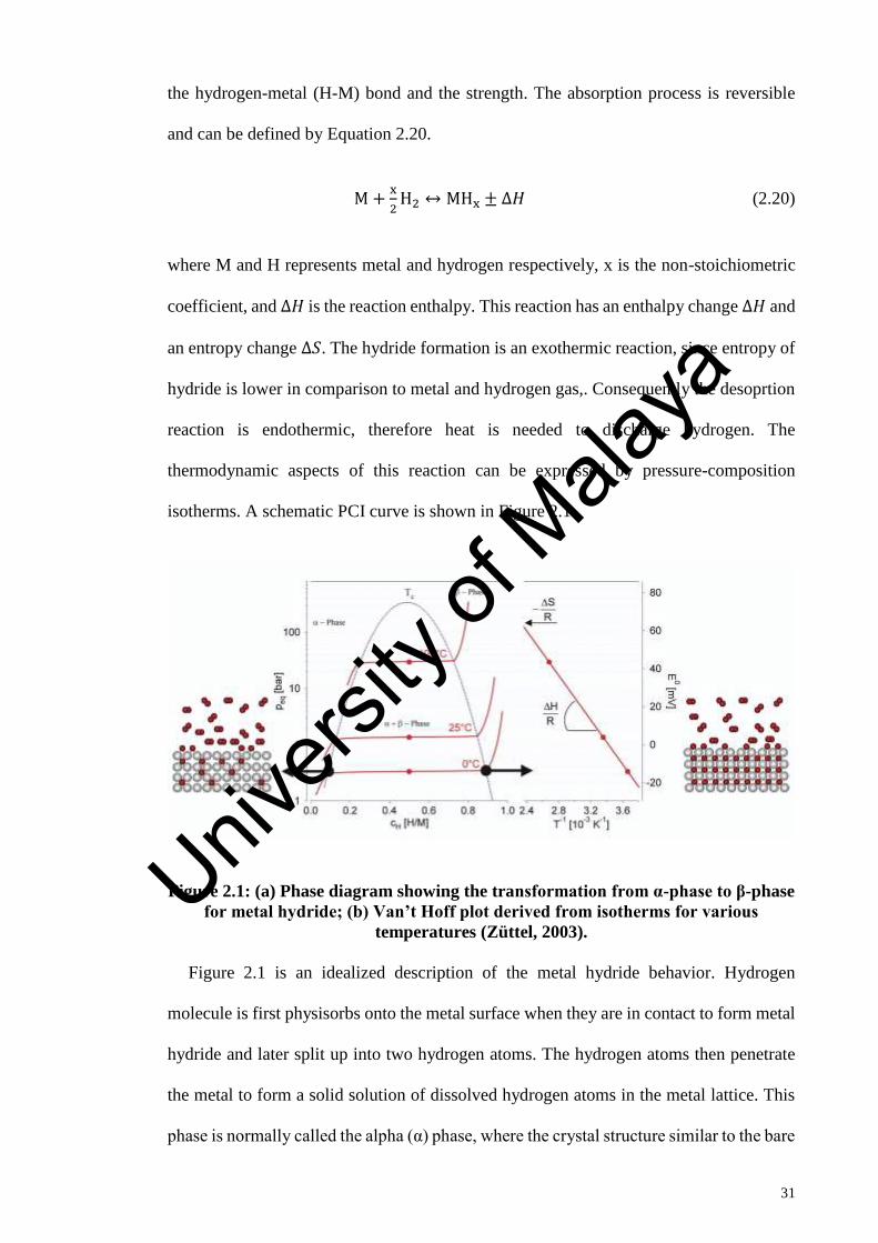
31
the hydrogen-metal (H-M) bond and the strength. The absorption process is reversible
and can be defined by Equation 2.20.
M +x
2H2 ↔ MHx ± ∆𝐻 (2.20)
where M and H represents metal and hydrogen respectively, x is the non-stoichiometric
coefficient, and ∆𝐻 is the reaction enthalpy. This reaction has an enthalpy change Δ𝐻 and
an entropy change Δ𝑆. The hydride formation is an exothermic reaction, since entropy of
hydride is lower in comparison to metal and hydrogen gas,. Consequently the desoprtion
reaction is endothermic, therefore heat is needed to discharge hydrogen. The
thermodynamic aspects of this reaction can be expressed by pressure-composition
isotherms. A schematic PCI curve is shown in Figure 2.1.
Figure 2.1: (a) Phase diagram showing the transformation from α-phase to β-phase
for metal hydride; (b) Van’t Hoff plot derived from isotherms for various
temperatures (Züttel, 2003).
Figure 2.1 is an idealized description of the metal hydride behavior. Hydrogen
molecule is first physisorbs onto the metal surface when they are in contact to form metal
hydride and later split up into two hydrogen atoms. The hydrogen atoms then penetrate
the metal to form a solid solution of dissolved hydrogen atoms in the metal lattice. This
phase is normally called the alpha (α) phase, where the crystal structure similar to the bare
Univers
ity of
Mala
ya

32
metal is observed. When the pressure of the hydrogen increase, the concentration of
hydrogen atoms dissolved into the metal will be in equilibrium with the gas phase
increase. Then, a higher concentration phase (β) begins to form when the concentration
of hydrogen atoms surpass a certain critical value where the H-H interaction becomes
significant. As a result, the system possess three phases which are α, β and hydrogen gas
phases as well as two components which are metal and hydrogen. From the Gibbs phase
rule, the degree of freedom (f) is:
𝑓 = 𝐶 − 𝑃 + 2 (2.21)
Where, C represents the components number and P denotes the phases number.
Therefore, if the process is isothermal (constant temperature), the concentration in the
two-phases region is increasing at a constant hydrogen pressure. When the α phase is
completely dissapeared, the pure β phase will be obtained and the system now has two
degree of freedom. The hydrogen pressure again increases with concentration when the
hydrogen enters into solid solution in the β phase.
During the transformation from the α to β phase, both of the two phases are in
equilibrium with each other as well as the gaseous hydrogen molecules. If the process
takes place at a constant temperature (isothermal process), following the Gibbs’ phase
rule, the hydrogen equilibrium pressure on the metal surface is then set to a value
depending on the specific metal hydride characteristics. This pressure is known as the
equilibrium plateau pressure, because it appears as a plateau in a pressure composition
isotherm (PCI). Derived from Van’t Hoff equation, the equilibrium plateau pressure 𝑃𝑒𝑞
for this reaction is given by:
ln𝑃𝑒𝑞
𝑃0=
∆𝐻
𝑅.𝑇−
∆𝑆
𝑅 (2.22)
Univers
ity of
Mala
ya

33
Where 𝑃0 is the reference pressure, ∆𝐻 and ∆𝑆 are the enthalpy and entropy of the
hydride formation (β phase), based on one mole of H 2. Generally, the ∆𝑆 change is
primarily given by the hydrogen gas standard entropy loss as it enters the metal lattice.
This suggests that the ∆𝑆 term can be assumed to be constant, although this is fairly
correct for complex metal hydrides. The ∆𝐻 term indicates the metal hydrides bond
stability. The enthalpy, ∆𝐻 of metal hydrides formation is negative in most cases,
reflecting its exothermic properties and hence 𝑃𝑒𝑞 rises exponentially with temperature.
From Figure 2.1, it can be seen that in α phase, the amount of hydrogen in the metal is
quite low compared to the actual metal hydride β phase where the amount of hydrogen is
quite high. To refill a metal hydride tank, adequate hydrogen is charged at a pressure
above 𝑃𝑒𝑞. The metal within the tank will then absorb hydrogen until it is completely
transformed to the β phase. By reducing the metal hydrides pressure or increasing the
temperature, the hydride will discharge hydrogen gas and gradually change from β phase
to α phase.
Therefore, the transition process from α phase to β phase, determined by the enthalpy
and entropy of the hydride formation, is very important for any promising metal hydride-
forming material. For a suitable practical applications, the transition pressure must be
near to 1 bar at relatively low temperature (~373 K). Assuming that ∆𝑆 of gaseous
hydrogen is 130 Jmol-1K-1, the ∆𝐻 of the hydride should be between -30 and -55 kJmol-1
to achieve 1 bar hydrogen equilibrium between 313 K and 423 K, based on the Van’t
Hoff equation. Unfortunately, none of the existence hydrides with high hydrogen capacity
has the required thermodynamic properties (Mao, 2011).
2.3.2 Kinetics of Metal Hydrides
Besides thermodynamic factors, the slow absorption kinetics of hydrogen is also an
obstacle for practical applications of metal hydrides. It is crucial to fully understand the
Univers
ity of
Mala
ya

34
hydrogen sorption process in order to determine which step is the rate-limiting step. The
hydrogen gas reaction with metals can be described as a simple one-dimensional potential
energy curve term as shown in Figure 2.2.
Figure 2.2: Simplified one-dimensional potential energy curve (Züttel, 2003)
As shown in Figure 2.2, far from the metal surface, the hydrogen molecule and two
hydrogen atoms potential are splitted by the dissociation energy (H2 → 2H, 𝐸𝐷 =
435.99 kJmol−1). When the hydrogen molecule approaches the metal surface
approximately one radius of hydrogen molecule (≈ 0.2 nm) from the metal surface, the
first interaction between both of them is the Van der Waals force which leads to the
physisorbed state (𝐸𝑃 ≈ 10 kJmol−1). Closer to the surface, for dissociation and
formation of the hydrogen metal bond to occur, the hydrogen needs to surpass the
activation obstacle.
The activation barrier height depends on the involved element surface. On the surface,
the hydrogen atoms that shares electrons with the metal atoms are then in chemisorbed
condition (𝐸𝐶 ≈ 50 kJmol−1 H2). The chemisorbed hydrogen atoms with high surface
mobility then interacting with each other to form surface phases at adequately high
Univers
ity of
Mala
ya

35
coverage. For the final step, the chemisorbed hydrogen atom can enter the subsurface
layer and eventually spread on the interstitial sites through the lattice of the host metal.
Hydride formation contains specific characteristic that makes this process different
from other gas-solid reactions. One of the special characteristic is high diffusivity of
hydrogen dissolved in the metal lattice. The other unique trait is that many metal-
hydrogen interaction starts to fracture at the initial reaction stage. Besides, there are many
factors that controlled the reaction rate of hydrogen. Briefly, the absorption and
desorption process of hydrogen can be divided into several independent steps as proposed
by (M. Martin et al., 1996) and listed below:
Hydrogen absorption
1. Physisorption of hydrogen molecules
on the surface of the metal.
2. Chemisorption and dissociation of
hydrogen molecules.
3. Surface penetration of the atomic
hydrogen into the bulk and formation
of α-solid solution.
4. Diffusion of hydrogen atoms through
the layer of α-solid solution, involving
interstitial and vacancy mechanisms.
5. Hydride formation at the interface of
the metal.
Hydrogen desorption
1. Hydride decomposition at the
hydride/α-solid solution interface.
2. Diffusion of hydrogen atoms through
the α-solid solution.
3. Penetration of hydrogen atoms from
bulk to the surface.
4. Recombination of chemisorbed
hydrogen atoms into the H2 molecules
and the physisorption on the surface.
5. Desorption from the surface into the
gaseous phase.
Univers
ity of
Mala
ya

36
There are certain cases where the conditions may be more complicated, such as by the
existence of subsurface sites with distinct absorption energy. During the hydrogen
desorption, analogous steps can be distinguish. The kinetic curve has its own properties
at each step that can be devised based on the amount of the fractional change over time.
The overall kinetic is limited by the rate-limiting step which is the slowest process. The
pressure and temperature influence on this curve also needs to be studied to infer the
reaction rate-limiting step.
Physisorption of hydrogen is a rapid process, and hence usually not a rate-limiting
process. For that reason, the surface equilibrium concentration can be assumed. Normally,
the rate-limiting step in the hydrogen absorption process is either the hydrogen
dissociation at the surface where surface concentration is important or the hydrogen
diffusion through the hydride to the metal/hydride interface, or both. The system needs to
be provided with sufficient activation energy for the dissociation to occur. For this
circumstance, the dissociation or recombination reaction is slow and might be the rate-
limiting step for the sorption process.
To enhance the rate-limiting step of physical and chemical sorption process, an
appropriate catalyst may be available. Unfortunately, metal surfaces are usually not clean
as it is passivated by oxygen, which inhibits the dissociation of hydrogen molecules and
the diffusion of hydrogen atoms into the bulk. Conversely, if the thickness of the hydride
layer increases (considering hydration occur from the outside to the core of the particle),
the restriction due to the diffusion through the hydride layer can become significant. For
detailed information on kinetic reaction, the apparent activation energy (𝐸𝑎) can be
calculated by using the same Arrhenius equation based on the isothermal
dehydrogenation results:
𝐾 = 𝐴𝑒(−𝐸𝑎𝑅𝑇
) (2.23)
Univers
ity of
Mala
ya

37
Where 𝐾 is the constant reaction rate (temperature dependent), 𝐴 is a pre-exponential
factor, 𝐸𝑎 is the apparent activation energy, 𝑅 is universal gas constant, and 𝑇 is absolute
temperature. Hence, it is crucial to figure out the value of 𝐾 before determining the
activation energy. Typically, 𝐾 can be figured out by analysing the isothermal hydrogen
sorption curves with suitable solid state kinetic rate expressions obtained from the solid
state reaction mechanism model such as nucleation, geometric contraction, diffusion and
reaction order models, which are based on different geometric particles and different
driving forces. Several of different rate expressions have been obtained from these
mechanisms.
2.4 Metal Hydrides Modelling Review
Metal hydride hydrogen storage system needs to have rapid charging and discharging
rates in order to compete with other commercialize energy storage system such as
gasoline tanks and batteries. Enhancing the reaction rate required the rate of heat transfer
in the reaction bed to be improved. There are some improvements that can be applied to
increase the heat and mass transfer in the metal hydride bed. To study the effect of heat
and mass transfer on the reaction rates, a mathematical model can be constructed to
illustrate the phenomena of heat and mass transfer in the metal hydride bed instead of
depending on experimental study only. This section describes a number of the previous
study involving the modelling and simulation of metal hydride tanks.
2.4.1 One Dimensional Approach: Model Limitations
One of the earlier one-dimensional mathematical model of metal hydrides is that of
Lucas & Richards (1984). They developed a detailed one-dimensional mathematical
model of a hydride bed which described the behaviour of the hydride bed during
absoprtion and desorption processes. These processes had been solved analytically based
on a one-dimensional transient heat conduction equation. Unlike the other hydride bed
Univers
ity of
Mala
ya

38
models previously studied in the literature, the model adopted in the study bed simulated
an actual, commercially available hydrogen storage system rather than an abstract ideal
situation. Therefore, this model provides an easy way to predict the time required to
absorb or release a given amount of hydrogen. However, the model implemented by
Lucas & Richards (1984) excluded the heat of reaction which was the main source of heat
produced in the system. In conclusion, there was a large dispute observed between
numerical and experimental results due to the oversimplified model.
Further investigations by using one-dimensional model are carried out by Mayer et al.
(1987). They developed a one-dimenisonal mathematical model that was able to explain
the transient heat and mass transfer reaction within metal hydride beds. The theoretical
predictions of this model were compared with reaction rates and pressure-temperature
distributions within the reaction beds where they were experimentally determined. The
temperature profiles for z direction and the heat transfer by convection were excluded
from the model. However, the experimental results clearly displayed that temperature
variations occur not only with r direction but also with z direction. Therefore, it was
concluded that it is important to consider the process along the z direction while the
convective effect may also be significant in tanks where the charging pressure is high.
In the previous literature, only models with constant physical properties of hydrogen
and metal hydride have been investigated. Da-Wen et al. (1988) felt that acquainting the
heat and mass transfer characteristics of reaction beds is significant and that model with
constant physical properties of hydrogen and metal hydrides could not present the
practical systems well. Hence, in 1988, they created a one dimensional model which
includes the effects of the effective thermal conductivity, the hydride physical properties
and other operating conditions on the metal hydride bed. The results indicate that the
reaction occurs throughout the hydride bed, but the major reaction take place in a rather
Univers
ity of
Mala
ya

39
narrow areas. They also found that the improvement of heat transfer in the metal hydride
bed is extremely important in reducing the time taken for the reaction.
Then, in 1992, Ram Gopal & Srinivasa Murthy (1992) developed another one-
dimensional heat and mass transfer model for metal hydrides beds with annular
cylindrical geometry. They claimed that existed models were restricted to certain alloys
only, and that a general work that predict the performance of different alloy systems were
unavailable. Therefore, a one-dimensional model in dimensionless form, which covers a
variety of alloys and operating parameters was created. As most works reported, Ram
Gopal & Srinivasa Murthy (1992) concluded that the rate-controlling resistance to heat
and mass transfer is the metal hydrides bed thermal resistance and the perfect approach
to design a reactor is to enhance the heat transfer characteristics by minimizing the bed
thickness and improving the bed conductivity. In 1993, Ram Gopal & Srinivasa Murthy
(1993) developed another new one-dimensional model. To make sure the study was a
generalised one, the input and output variables were combined into non-dimensional
parameter and the properties as well as operating parameters is varied. The variation of
the metal hydride properties and operating parameters was large so that the results could
be used for a many alloys and systems. Again, they concluded that an enhancement in
heat transfer is most important for metal hydride system.
By using a revised one-dimensional mathematical model, Gopal et al. (1995) has
displayed a good comparison between numerical and experimental results. They
investigated the effect of different cooling fluid temperatures on hydriding/dehydriding
characteristics theoretically and experimentally and the results showed that higher heat
and mass transfer rates could be achieved at lower cooling fluid temperature.
Unfortunately, some inconsistency in the bed temperatures caused by the reactor thermal
mass was observed. The conclusion of their study was that the presented model can only
Univers
ity of
Mala
ya

40
be used for beds with small thickness and for other mathematical model development, the
effect of pressure drop and reactor thermal mass must be taken into account to correctly
predict the hydride beds performance.
Therefore, it can be assumed that one-dimensional models may not be able to fully
reflect the heat and mass transfer processes in the reaction beds because some of the
important effects of the design and the system behavior prediction are mostly excluded.
This leads researchers to develop other alternative such as two and three dimensional
approach to this problem.
2.4.2 Two and Three-Dimensional Models
In 1989, Da-Wen et al. (1989) created a two-dimensional model as an extension for
their previous one-dimensional model. The model contain the general equations for
effective thermal conductivities and kinetics for metal hydrides beds as well as pressure-
concentration-temperature (P-C-T) curves, thus forming a “more universal” model. The
two-dimensional model has been validated against experimental results with constant and
varying properties to observe which of the models is more accurate. Sun & Deng (1990)
presented their model in more detail in 1990, and present a numerical solution based on
finite difference approximations by using alternating-direction implicit method. There
was good agreement between the numerical and experimental results.
In their series of papers, A. Jemni et al. (1995a, 1995b) created two dimensional
mathematical model for heat and mass transfers during hydrogen sorption process within
metal hydride bed. The numerical simulation showed that the reactor dimensions, the inlet
pressure and temperature during absorption, and the heating fluid outlet pressure and
temperature during desorption, were significant. They also concluded that the assumption
of thermal equilibrium was not valid for the whole reactor and that the heat transfer by
Univers
ity of
Mala
ya

41
convection which could be neglected. This study indicated that enhancing the solid,
effective thermal leads to substantial improvement in reactor performance.
Later, in 1997, Nasrallah & Jemni (1997) also validated the main assumptions
commonly used by different authors in producing mathematical models for metal hydride
reactions. The validation was done by comparing the numerical results with and without
the use of the assumptions for LaNi5-hydrogen reactor. This study concluded that the
assumption of local thermal equilibrium, negligible pressure variation and the effect of
hydrogen concentration on equilibrium pressure were almost valid for all conditions. The
conclusion is important as it allows authors to use the simplified model with given
assumptions to correctly illustrate the heat and mass transfer process in the reactor.
However, even with the simplified mathematical model, there were some parameters
that need to be precisely determined, including the effective thermal conductivity,
equilibrium pressure, reaction kinetics and the conductivity between hydride beds and
fluid around tank. Thus, to address this problem, an attempt was made in the next
experimental study of Jemni et al. (1999) where the developed theoretical model was
validated against experimental results. In this work, they determined all the parameters
experimentally. As conclusion, they obtained good agreement between the experimental
and the calculated results.
In 2000, Nakagawa et al. (2000) proposed a two dimensional mathematical model
which described transient heat and mass transfer in metal hydride bed. They validated the
assumptions of local thermal equilibrium and negligible convection effect on heat transfer
in detail and also bring into account the influence of reacted fraction on thermophysical
properties such as specific heat, thermal conductivity, and metal hydrides particle
diameter. For this study, they came up with the same conclusion by A. Jemni et al. (1995a,
1995b) that temperature equilibrium between gas and solid did not occur throughout the
Univers
ity of
Mala
ya

42
bed but, almost true for the whole volume. Still, they noted that the convection only
improved the hydriding process initially and caused a bad effect afterward.
In 2001, Mat et al. (2001) adopted the mathematical model from A. Jemni et al. (1995a)
and applied it to the available experimental study in literature to investigate the basic
mechanisms of hydride formation and the heat and mass transfer process which occur
within the hydrides bed. It was observed that in the regions with lower equilibrium
pressure, the hydride formation was enhanced where the hydride formation increased
rapidly at the beginning and later started to slow down when the bed temperature increase
due to the exothermic reaction. The model successfully predicted the experimental
results. Afterwards, they extended the analysis to three-dimensional models which
includes three-dimensional complex heat and mass transfer and chemical reaction in
metal hydride (Aldas et al., 2002). The important founding of the analysis was that the
main parameter in the absorption process was equilibrium pressure, which strongly
depended on temperature as in the two-dimensional model. The important implication of
this study was that the absorption process can be represented by a two-dimensional or
three-dimensional model.
Univers
ity of
Mala
ya

43
CHAPTER 3: METHODOLOGY
3.1 Introduction
In this chapter a three-dimensional mathematical model is presented for describing the
absorption processes that take place in porous metal hydride compacts of cylindrical
shape that conforms the actual setup used in the experiment. First, a series of equations
governing the heat and mass transfer process as well as the initial and boundary conditions
are discussed. These equations are first implemented in the COMSOL Multiphysics
simulation using literature data from the references (Yun Wang et al., 2009) and (Nam et
al., 2012) to validate the three-dimensional mathematical model.
After the mathematical model validation, these equations then implemented again in
the COMSOL Multiphysics for the simulation of the three-dimensional model describing
actual hydrogen storage canister used in the prior experiment. The simulation are
conducted using identical conditions, as used in the previous experiment, and both of the
simulation and experiment results are compared for validation purpose. The purpose of
the simulation of the actual metal hydrides canister is to improve the understanding of the
behavior of an actual metal hydride storage system. For instance, in metal hydride system,
the canister is completely sealed, therefore it is impossible to observe the phenomena that
are occurring within the canister.
Moreover, simulation is a flexible process which means that once the model is created,
it can be easily utilized for other work conditions. Therefore, a parametric study is
performed on the three-dimensional model describing actual hydrogen storage canister to
study the effect and consequences of different metal hydrides properties on an actual
metal hydrides storage system performance. Finally, a systematic optimization-based
strategy for the design and operating conditions of metal hydride beds for hydrogen
storage is performed to maximize the amount of hydrogen stored within the hydride.
Univers
ity of
Mala
ya

44
Generally, this study focused on model validation and simulation of an actual AB2 type
metal hydrides canister, for which Ti-Mn based (Ti0.99Zr0.01V0.43Fe0.09Cr0.05Mn1) metal
hydrides system is used in the experimental and simulation procedure.
3.2 Description of Dynamic Model
Metal hydrides bed is solid material with internal pore structures called porous media.
Therefore, the mass and heat transfer aspects of metal hydrides bed are described through
the mechanism of fluid flow and heat transfer in porous media.
In 1856, Darcy first quantified the relation between solid and liquid phases in porous
media by identifying that the flow rate is proportional to the pressure gradient. The
relationship can be applied for most porous media, but cannot be applied for non-
Newtonian fluids, high velocity Newtonian liquids, and gases at very low or high
velocities. Besides, the friction within the fluid and the momentum exchange between
solid and fluid phases also neglected by Darcy.
In porous media, the molecules move follows the tortuous pathway in the void space
(Truskey et al., 2004). There are two approaches that can describe the fluid flow in porous
media which is to numerically solve the governed equation for fluid flow in individual
pores or to assume that the porous medium is a homogenous material which is known as
continuum approach. In the continuum approach, the volume fraction of the void space is
assumed to be volumetric porosity, 𝜀, and the volume fraction of the solid phase is (1 −
𝜀).
For the heat transfer mechanism, the equation that describes the first law of
thermodynamics in a porous medium is used. The medium is adopted to be isotropic
whereas radiation effects, viscous dissipation, and the work done by pressure changes are
negligible for the sake of simplicity. Besides, there is local thermal equilibrium assumed
Univers
ity of
Mala
ya

45
so that the temperatures of the solid and gas phases inside the vessel are the same. In
general, for heat transfer in porous medium, the overall thermal conductivity depends on
the medium geometry. If the conduction of heat in the solid and gas phases occurs in
parallel, then the efficient conductivity, 𝑘𝑒 is the weighted arithmetic mean of the
conductivities 𝑘𝑔 and 𝑘𝑚 where 𝑘𝑒 = 𝜀𝑘𝑔 + (1 − 𝜀)𝑘𝑚.
3.2.1 Model Assumption
The following assumptions are made for the flow and transport process in porous medium
(Nasrallah & Jemni, 1997):
1. The gas phase (hydrogen) is treated as an ideal gas from thermodynamic view.
2. The solid phase (powdery metal alloy) is considered as an isotropic and homogenous
porous medium.
3. The media (solid metal and hydrogen gas) is assumed to be in local thermal
equilibrium. That means that the gas temperature and the metal temperature inside the
vessel is the same.
4. The volumetric expansion of the metal hydride bed during absorption process is
ignored.
5. The metal hydride properties such as porosity, permeability and thermal conductivity
remain constant during the absorption process.
3.2.2 Governing Equations
Under these assumptions, the metal hydrides container is governed by the conservation
equation of mass, momentum and thermal energy (Freni et al., 2009).
Univers
ity of
Mala
ya

46
3.2.2.1 Mass conservation
Mass conservation equation for hydrogen gas is denoted by Equation (3.1):
𝜀𝜕𝜌𝑔
𝜕𝑡+ ∇(𝜌𝑔𝒖𝒈) = −𝑆𝑚 (3.1)
Where the gas density, 𝜌𝑔, can be expressed by Equation (3.2) (ideal gas law):
𝜌𝑔 =𝑝𝑔.𝑀𝐻2
𝑅𝑔𝑇 (3.2)
The mass balance equation of the solid metal hydride then can be presented by Equation
(3.3):
(1 − 𝜀)𝜕𝜌𝑚
𝜕𝑡= 𝑆𝑚 (3.3)
In Equations (3.1) and (3.3), 𝜀 represents the porosity of the metal hydride tank and 𝑆𝑚
denotes the rate of hydrogen absorption per unit volume. Therefore, the volumetric mass
source term, 𝑆𝑚, is zero in the expansion volume sub-region, but nonzero in the metal
hydride sub-region. Then, 𝑆𝑚 can be shown as follows (Jemni & Nasrallah, 1995).
𝑆𝑚 = 𝐶𝑎𝑒𝑥𝑝 (−𝐸𝑎
𝑅𝑔𝑇) 𝐼𝑛 (
𝑃𝑔
𝑃𝑒𝑞) (𝜌𝑚𝑠 − 𝜌𝑚) (3.4)
Where 𝐶𝑎 is absorption rate constant, 𝐸𝑎 the activation energy, 𝜌𝑚𝑠 the density of metal
hydride at the saturation state and 𝑃𝑒𝑞 the equilibrium pressure for hydrogen absorption
that is greatly dependent on the temperature and 𝐻/𝑀 atomic ratio. Their correlation can
be derived through van’t Hoff’s relationship as follows (Nam et al., 2012):
𝑝𝑒𝑞 = 𝑝𝑒𝑞𝑟𝑒𝑓
. 𝑒𝑥𝑝 (∆𝐻
𝑅𝑔𝑇−
∆𝑆
𝑅𝑔) = 𝑓 (
𝐻
𝑀) . 𝑒𝑥𝑝 (
∆𝐻
𝑅𝑔𝑇−
∆𝑆
𝑅𝑔) (3.5)
Univers
ity of
Mala
ya

47
3.2.2.2 Momentum conservation
Momentum balance equation consist of Darcy’s term to describe the momentum transfer
due to pressure gradient in the metal hydrides porous media. The hydrogen gas velocity
(𝒖𝒈) which represent by Equation (3.6), can be computed using the Darcy’s law (Jemni
& Nasrallah, 1995):
𝒖𝒈 = −𝐾
𝜇𝑔∇𝑃𝑔 (3.6)
Where K is permeability, 𝜇𝑔 is hydrogen gas dynamic viscosity, 𝑃𝑔 is gas pressure.
The solid permeability, 𝐾 is given by the Kozeny – Carman’s equation:
𝐾 =𝑑𝑝
2𝑒3
150(1−𝜀)2 (3.7)
Where, 𝑑𝑝 is the diameter of metal hydride particle.
3.2.2.3 Energy conservation
Assuming there is thermal equilibrium between the hydrogen gas and hydride bed, the
energy equation is combined in the simulation instead of separate equations for the
hydrogen gas and hydride bed which is denoted by Equation (3.8):
(𝜌𝐶𝑝)𝑒
𝜕𝑇
𝜕𝑡+ (𝜌𝐶𝑝)𝑔
(𝒖𝒈 ∙ ∇T) = ∇ ∙ (𝑘𝑒∇T) + 𝑆𝑇 (3.8)
Where, 𝑆𝑇 is the heat source term given by Equation (3.9):
𝑆𝑇 = 𝜁 (∆𝐻
𝑀𝑔) = 𝑚 (∆𝐻 − 𝑇(𝐶𝑝𝑔 − 𝐶𝑝𝑚)) (3.9)
Considering only parallel heat conduction in solid and gas phases, the following
expression for effective specific heat and thermal conductivity can be presented by
Equation (3.10):
Univers
ity of
Mala
ya

48
(𝜌𝐶𝑝)𝑒= 𝜀𝜌𝑔𝐶𝑝𝑔 + (1 − 𝜀)𝜌𝑠𝐶𝑝𝑚 (3.10)
The effective thermal conductivity is given by Equation 3.11:
𝑘𝑒 = 𝜀𝑘𝑔 + (1 − 𝜀)𝑘𝑚 (3.11)
The volumetric energy source term, 𝑆𝑇 in Equation (3.8) denotes the heat release during
the exothermic reaction of hydrogen absorption; therefore, the value is positive in the
porous metal sub-region. Thus, 𝑆𝑇 can be indicated as the product of the enthalpy change
during hydrogen absorption (∆𝐻) and the volumetric hydrogen absorption rate, 𝑆𝑚, as
shown by Equation (3.12).
𝑆𝑇 = 𝑆𝑚[∆𝐻 − 𝑇(𝐶𝑝𝑔 − 𝐶𝑝𝑚)] (3.12)
3.2.3 Initial Conditions
Initially, the metal hydride canister is assumed to be in thermodynamic equilibrium, so
the initial conditions are given by Equations (3.13)-(3.15):
𝑇 = 𝑇0; (3.13)
𝑝 = 𝑝0; (3.14)
𝜌𝑚 = 𝜌𝑚,0 (3.15)
where 𝜌𝑚,0 describes the initial hydrogen-empty metal hydride density. The initial value
of hydrogen gas velocity is zero as hydrogen gas is absent in the metal hydride canister.
𝒖𝒈 = 0 (3.16)
Univers
ity of
Mala
ya

49
3.2.4 Boundary Conditions
As for boundary conditions, no-slip velocity and no-flux condition are applied as the
boundary walls are assumed to be impermeable. Therefore, the energy equation becomes
as shown below where convection boundary condition is applied between the canister
walls and exterior air.
𝑘𝑒𝜕𝑇
𝜕�⃗� = ℎ(𝑇𝑒𝑥𝑡 − 𝑇) (3.17)
Where �⃗� is the normal unit vector out of the vessel wall and 𝑇𝑒𝑥𝑡 is the exterior air
temperature. Inlet conditions are enforced to the inlet region of computational domain
according to the specified temperature and pressure.
3.2.5 Implementation of System into COMSOL Multiphysics
The governed mathematical equations are implemented into COMSOL Multiphysics
software. COMSOL Multiphysics software uses the finite element method to solve the
partial differential equations and time-dependent solver in the model since the dynamic
conditions in the metal hydrides tank require time-dependent partial differential equation.
The mathematical sorption model for porous metal hydrides compacts takes into account
mass conservation of hydrogen-absorbed metal alloy, Darcy flow in the porous medium
and heat generation by exothermic reaction during absorption. Besides, the COMSOL
Multiphysics software enables the governing equations implementation by entering each
differential equation as a separate physics mode, therefore permitting each one to have
unique initial and boundary conditions.
3.2.5.1 Physics Mode
ODE and DAE Interfaces
The Domain ODEs and DAEs interface, found under mathematic is used to add space-
independent equations to domains. The field variables can represent additional states and
Univers
ity of
Mala
ya

50
the corresponding equations which can be ODEs, algebraic equations, and DAEs. In this
study, it is used to simulate the mass conversation of hydrogen absorbed and is governed
by Equation (3.3) and state variable 𝜌𝑚.
Darcy’s Law Interface
The Darcy’s Law interface, located under the Porous Media and Subsurface Flow
physics interface, is applied to model fluid flow through interstices in a porous medium.
It is valid for low-velocity flows or media where the value of permeability and porosity
are varied, and for which the pressure gradient is the major driving force and the flow is
mostly determined by the frictional resistance within the pores. Set up multiple Darcy's
Law interfaces to model multiphase flows involving more than one mobile phase. The
Darcy's Law interface can be utilized for stationary and time-dependent analysis. This
physic mode used for hydrogen flow in porous media is the combination of Equations
(3.1) and (3.6) and the state variable 𝑝𝑔.
Heat Transfer Interface
The Heat Transfer in Porous Media interface, located under Heat Transfer physics is
used to simulate heat transfer by conduction, convection, and irradiation. On all domain,
the Heat Transfer in Porous Media model is active by default. All functionality including
other domain types, such as a solid domain, is also applicable. The temperature equation
expresses in the porous media domain corresponds to the convection-diffusion equation
with thermodynamic properties averaging models to account for both solid matrix and
fluid properties. For this study, this physic mode is the final physics mode, which is for
metal hydride energy conservation is governed by Equation (3.8) and the state variable is
𝑇.
The physics mode and implementation of governed equations into COMSOL
Multiphysics simulation is summarized in the Table 3.1.
Univers
ity of
Mala
ya

51
Table 3.1: Table of physics mode and implementation of governed equations
Purpose Module Application mode Governed
equation State
variable
Mass source term
(Mass conservation) Mathematics
ODE and DAE
Interfaces ⇒Domain
ODEs and DAEs
(dode)
Eq. (3.2) 𝜌𝑚
Fluid flow in porous
media (Momentum
conservation) Fluid Flow
Porous Media and
Subsurface Flow
⇒Darcy’s Law
Interface (dl)
Eq. (3.1)
and Eq.
(3.6) 𝑝𝑔
Energy conservation Heat
transfer Heat transfer in
Porous Media (ht) Eq. (3.8) 𝑇
3.3 Validation of Mathematical Model
Numerical simulation is first conducted to validate the presented three-dimensional
mathematical model for metal hydrides system. When a mathematical model of metal
hydrides vessel is developed, it is significant to compare the model predictions to
experimentally validated study. Jemni and Ben Nasrallah have carried out comprehensive
modelling work, including experimental validation, and their experimental data have been
used for model validation by other researchers such as Wang et al. (2009) and Nam et al.,
(2012).
Therefore, it is more convincing to compare the results of the model presented in this
study with the experimentally validated model results from Wang et al. (2009) and Nam
et al., (2012). The purpose of validating against experimentally validated model results
and not directly against the experimental results is because the model results are more
precise and based on a scenario that is easy to replicate while experimental results are
usually limited
3.3.1 Overview of the Model
Since the mathematical model which has been presented in Section 3.2 is been validated
with previous experimentally validated model results from Wang et al. (2009) and Nam et
Univers
ity of
Mala
ya
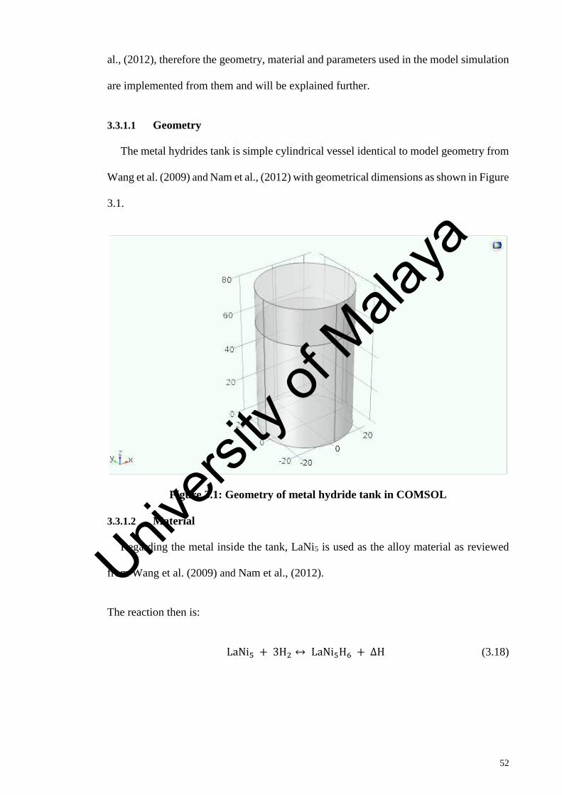
52
al., (2012), therefore the geometry, material and parameters used in the model simulation
are implemented from them and will be explained further.
3.3.1.1 Geometry
The metal hydrides tank is simple cylindrical vessel identical to model geometry from
Wang et al. (2009) and Nam et al., (2012) with geometrical dimensions as shown in Figure
3.1.
Figure 3.1: Geometry of metal hydride tank in COMSOL
3.3.1.2 Material
Regarding the metal inside the tank, LaNi5 is used as the alloy material as reviewed
from Wang et al. (2009) and Nam et al., (2012).
The reaction then is:
LaNi5 + 3H2 ↔ LaNi5H6 + ΔH (3.18)
Univers
ity of
Mala
ya

53
3.3.1.3 Parameters used in Simulation
The kinetic parameters for Equation (3.1), thermal–physical properties of LaNi5 and
LaNi5 hydride (LaNi5H6), and operating conditions for the absorption process used in the
simulation are given in Table 3.2.
Table 3.2: List of parameters used in simulation for 𝐋𝐚𝐍𝐢𝟓 system
Parameter Designation Value
Hydrogen absorption constant on metal alloy 𝐶𝑎ℎ 59.187 s−1
Hydrogen activation energy 𝐸𝑎ℎ 21179.6 J/mol
Hydrogen heat capacity 𝑐𝑝𝑔 14890 J/kg. K
Metal heat capacity 𝑐𝑝𝑚 419 J/kg. K
Reaction enthalpy ∆𝐻 29879 J/mol
Reaction entropy ∆𝑆 108 J/mol. K
Porosity 𝜀 0.63
Heat transfer coefficient ℎ𝑐𝑡 1652 W/m2. K
Permeability 𝐾 1 × 10⁻⁸ m2
Hydrogen thermal conductivity 𝑘𝑔 0.1672 W/m.K
Metal thermal conductivity 𝑘𝑚 3.18 W/m.K
Hydrogen molar weight 𝑀𝑔 2 g/mol
Metal molar weight 𝑀𝑚 432 g/mol
Hydrogen dynamic viscosity 𝜇 8.411 × 10⁻⁶ Pa. s
Empty metal hydride density 𝜌𝑚0 4200 kg/m3
Saturated metal hydride density 𝜌𝑚𝑠 4264 kg/m3
Atm pressure 𝑝𝑎𝑡𝑚 1 bar
Inlet pressure 𝑝𝑖𝑛 10 bar
Reference pressure 𝑝𝑟𝑒𝑓 10 bar
Ambient temperature 𝑇𝑎𝑚𝑏 293 K
Reference temperature 𝑇𝑟𝑒𝑓 303 K
Gas constant R 8.314 J/mol. K
Pie 𝜋 3.142857143
3.4 Validation of Actual Simulation
For the actual simulation of real metal hydrides system, the three-dimensional model
validated in the previous section is implemented into COMSOL Multiphysics using an
actual hydrogen storage canister used in the prior experiment. In order to accurately
present the actual simulation of the real metal hydrides tank, some experimental data is
required. Some experimental data for the absorption of metal hydrides is available from
Univers
ity of
Mala
ya

54
previous study of other researcher’s team which has been developed and performed in the
Hydrogen Fuel Cell laboratory of Universiti Malaya (UM).
Therefore, the simulation is conducted using identical conditions, as used in the
experiment, i.e.: geometry, material, operating condition in order to validate the
computational simulation data with actual metal hydrides data. The objective of the
validation is not to exactly match the values obtained by both methods, but to achieve the
same tendency and the same orders of magnitude.
3.4.1 Overview of the Model
The distinct aspect between the model implemented in Section 3.3 and the final model,
are the geometry, as well as the properties that come with it, for example material,
parameters and operating condition as it is adapted from the actual hydrogen storage
canister used in the prior experiment.
3.4.1.1 Geometry
At first, a simple cylinder identical to model geometry from Wang et al. and Nam et
al. was drawn for model validation purpose, but lastly the actual geometry of the real
metal hydride canister is implemented. To acquire that final geometry few measurements
of the actual canister are taken and a three-dimensional solid geometry is created on
COMSOL Multiphysics. The units are set on millimeters. The geometry dimensions of
the metal hydrides canister is as shown in Figure 3.2. Univers
ity of
Mala
ya

55
Figure 3.2: Geometry of the actual metal hydride tank in COMSOL
3.4.1.2 Material
For this study, an AB2-type (Laves phase) alloy is chosen for their excellent hydrogen-
storage capacity and operating conditions. Most of the Laves phases exhibit high
capacities, fast kinetics, long life and a relatively low cost in comparison to the LaNi5-
related systems. Therefore, a commercially available AB2-type metal hydrides tank is
selected from Horizon Fuel Cell Technologies. The definite composition of the alloy used
in the hydride product is unknown, so a scanning electron microscope (SEM) which is
used to analyze the samples. The electrons interact with the atoms in the sample,
producing various signals that carry information about the sample's surface topography
and composition. Based on the SEM result, Ti0.99Zr0.01V0.43Fe0.09Cr0.05Mn1.5 alloy is
selected considering its similar element number. Some properties of this material are
obtained from (Satheesh & Muthukumar, 2010) and shown in Table 3.3.
Univers
ity of
Mala
ya

56
Table 3.3: List of properties of Ti0.99Zr0.01V0.43Fe0.09Cr0.05Mn1.5 alloy
Parameter Designation Value
Hydrogen absorption constant on metal alloy 𝐶𝑎ℎ 100𝑠−1
Hydrogen activation energy 𝐸𝑎ℎ 28000 J/mol
Metal heat capacity 𝑐𝑝𝑚 500 J/kg. K
Reaction enthalpy ∆𝐻 20120 J/mol
Reaction entropy ∆𝑆 97.4J/mol. K
Porosity 𝜀 0.65
Convection coefficient ℎ𝑐𝑡 500W/m2. K
Permeability 𝐾 1 × 10⁻⁸m2
Metal thermal conductivity 𝑘𝑚 1.6 W/m. K
Metal molar weight 𝑀𝑚 160.24 g/mol
Hydrogen dynamic viscosity 𝜇 9.5 × 10⁻⁶Pa. s
Empty metal hydride density 𝜌𝑚0 5500 kg/m3
Saturated metal hydride density 𝜌𝑚𝑠 5563 kg/m3
3.4.1.3 Parameters used in Simulation
The parameters and operating conditions used in the simulation are listed in Table 3.4.
Table 3.4: List of parameters and operating conditions used in the simulation
Parameter Designation Value
Hydrogen absorption constant on metal alloy 𝐶𝑎ℎ 100𝑠−1
Hydrogen activation energy 𝐸𝑎ℎ 28000 J/mol
Hydrogen heat capacity 𝑐𝑝𝑔 14290 J/kg. K
Metal heat capacity 𝑐𝑝𝑚 500 J/kg. K
Reaction enthalpy ∆𝐻 20120 J/mol
Reaction entropy ∆𝑆 97.4J/mol. K
Porosity 𝜀 0.65
Convection coefficient ℎ𝑐𝑡 500W/m2. K
Permeability 𝐾 1 × 10⁻⁸m2
Hydrogen thermal conductivity 𝑘𝑔 0.182 W/m. K
Metal thermal conductivity 𝑘𝑚 1.6 W/m. K
Hydrogen molar weight 𝑀𝑔 2 g/mol
Metal molar weight 𝑀𝑚 160.24 g/mol
Hydrogen dynamic viscosity 𝜇 9.5 × 10⁻⁶Pa. s
Empty metal hydride density 𝜌𝑚0 5500 kg/m3
Saturated metal hydride density 𝜌𝑚𝑠 5563 kg/m3
Atmospheric pressure 𝑝𝑎𝑡𝑚 1 bar
Inlet pressure 𝑝𝑖𝑛 20 bar
Initial pressure 𝑝0 8 bar
Reference pressure 𝑝𝑟𝑒𝑓 20 bar
Ambient temperature 𝑇𝑎𝑚𝑏 305.15 K
Univers
ity of
Mala
ya

57
Table 3.4 continued.
Parameter Designation Value
Inlet temperature 𝑇𝑖𝑛 306.15 K
Initial temperature 𝑇0 293.15 K
Reference temperature 𝑇𝑟𝑒𝑓 293.15 K
Gas constant R 8.314 J/mol. K
Pie 𝜋 3.142857143
3.4.1.4 Mesh Sensitivity Analysis
Prior to analyzing solutions developed by the model, a mesh sensitivity analysis is
conducted to ascertain that a suitable mesh size and solution time are utilized. The mesh
sensitivity analysis is conducted by observing the effect of modifying the grid size on the
evolution of temperature and density over time. The idea of this sensitivity analysis is to
start with an extremely coarse mesh and refine it gradually in order to get a rather fine
mesh where the meshes are generated by tetrahedral, creating a grid. The computational
simulation will be simulated using all the developed meshes and then the optimum mesh
for the absorption process is decided.
3.4.2 Experimental Set Up
As explained in Section 3.4 of the project, the experimental data for the validation
purpose is collected from previous study of other researcher’s team. The experiment has
been developed and conducted using a test rig at the Hydrogen Fuel Cell laboratory of
Universiti Malaya (UM). Figure 3.3 shows the actual hydrogen test rig located at
Hydrogen Fuel Cell laboratory of Universiti Malaya (UM).
Univers
ity of
Mala
ya

58
Figure 3.3: Hydrogen test rig located at Hydrogen Fuel Cell laboratory of
University of Malaya (UM)
In order to briefly understand the experimental procedure, a simple diagram for the
experimental set up is illustrated in Figure 3.3 and followed by a brief explanation of the
experimental procedure.
Figure 3.4: Simple experimental set up diagram
A simple diagram for the experimental procedure is shown on Figure 3.4. The diagram
explains starting from the process of producing the hydrogen, compression of the gas and
finally the storage system. Filtration of the tap water through the water filtration process
Univers
ity of
Mala
ya

59
produced demineralized water where the allowable conductivity was less than 5 𝜇𝑆. The
pure water was supplied to the electrolyser which broke up the water into two gases,
hydrogen and oxygen as shown in the equation below. The hydrogen gas produced from
this process was 99.9 % pure.
𝐻2𝑂 + 𝑒𝑛𝑒𝑟𝑔𝑦 → 𝑂2(𝑔𝑎𝑠) + 𝐻2(𝑔𝑎𝑠) (3.2)
To summarized the process, the water inside electrolyser is separated by method of
electrolysis. The products of the electrolysis, hydrogen and oxygen gas, entrains the
electrolyte up to separating which separate the gas phase from excess liquid phase by method
of weight separation. Water which is heavier than air and under the pressure of the separating
vessel will fall back down to the bottom of the separating vessel, whereas the hydrogen and
oxygen gas along with any other components that is carried by these gases will rise to the top
of the vessel. Water that has fallen to the bottom of the vessel will again flow into the cell
stack to go through electrolysis again.
Then, the hydrogen gas was supplied to the water piston jet compressor that was
capable of compressing the gas up to 200 bar, but the maximum pressure of the hydrogen
that mass flow meter can withstand was 125 bar. For the sake of compensating the mass
flow meter limit, the hydrogen gas was compressed up to 125 bar only. Finally the gas
was supplied to the storage cylinder type-II as a source tank. A 4 mm tubing was
connected between both type-II and metal hydrides cylinders as the receiver. A globe
valve was fitted at each cylinder and another globe valve was fitted at the coriolis mass
flow meter for control during the experiment. The data collected during the experiment
is recorded using Prolink software.
The metal hydrides canister used in the experiment is a commercial metal hydrides
tank called MH-350 Metal Hydride Canisters. The MH-350 Metal Hydride Canisters are
developed and manufactured by Horizon Fuel Cell Technologies and are designed with
Univers
ity of
Mala
ya

60
aluminum alloy as the canister material and AB2 (Ti-Mn based) alloy for the hydrides bed
material. This AB2 alloy can be able to absorb hydrogen, expand and release heat until
saturation. The internal pressure of the hydrides tank remains at 8 Bar at ambient
temperatures of 20℃-25℃ . When the canister valve is opened and pressure is reduced,
hydrogen gas will be released from the alloy material which will absorb heat. The rate of
hydrogen release will be decreased if the rate of heat absorption decreases. The aluminum
alloy which used for canister enclosure has excellent heat conductivity properties that can
facilitate heat conduction of the alloy during gas intake and release processes. Figure 3.5
shows the geometry of the MH-350 Metal Hydride Canisters.
Figure 3.5: MH-350 Metal Hydride Canisters
3.5 Sensitivity Analysis of Metal Properties
After validating the actual simulation with experimental result, a sensitivity analysis
on metal hydrides properties is performed to study the effect of metal hydrides properties
on the behavior of the hydrogen storage system during the absorption process especially
in term of mass and heat transfer. The metal properties sensitivity analysis is conducted
by performing a parametric studies using computational simulation on variation of small
and major influence parameters such as porosity (ε), permeability (𝐾), metal thermal
conductivity (𝑘𝑚), hydrogen absorption constant on metal (c𝑎), activation energy (𝐸𝑎) and
heat transfer coefficient (ℎ𝑐𝑡 ). Table 3.5 shown the list of parameter values used in the
Univers
ity of
Mala
ya

61
parametric studies for each parameter. The parameter values are selected by reviewing
others studies (Satheesh & Muthukumar, 2010), (Busqué Somacarrera, 2015).
Table 3.5: List of parameters used in the parametric studies for each parameter.
Parameter Values
Porosity ,ε 0.10 0.30 0.50 0.65 0.80
Permeability, 𝐾 (m2)
1 × 10⁻¹⁰ 1 × 10⁻⁸ 1 × 10⁻⁵ 1 × 10⁻³ 1.00
Thermal conductivity, 𝑘𝑚
(W/m.K)
0.10
1.00
1.60
6.50
10.00
Absorption constant , c𝑎
(s−1)
1
10
50
100
305
Activation energy, 𝐸𝑎
(J/mol)
2000
2800
3500
5000
10000
Heat transfer coefficient, ℎ𝑐𝑡
(W/m2. K)
10
50
200
500
1000
3.6 Optimization on Metal Hydrides System
Optimization of the operating condition used for a metal hydride based hydrogen
storage system which can influence the gravimetric hydrogen storage density, and
refueling time. Therefore, a study on the operating condition is presented to find the
optimal operating strategy which includes operating pressure and temperature so as to
minimize the storing time, while satisfying a number of operating constraints. To study
the effect of pressure, five different pressure values are studied by keeping the other
operating parameters as constant. The pressure values are varied from 10 to 50 bar as
shown in Table 3.6. For temperature, the same procedure as pressure is used by varying
the temperature value from 25 to 50 ℃ as illustrated in Table 3.6.
Table 3.6: Operating value used in the optimization studies for charging pressure
and temperature
Parameters Values
Charging pressure (bar) 10 20 30 40 50
Temperature (℃) 25 33 40 43 50
Univers
ity of
Mala
ya

62
CHAPTER 4: RESULT AND DISCUSSION
4.1 Introduction
In this chapter, the results from the three-dimensional simulation of metal hydrides bed
using COMSOL Multiphysics are presented and discussed in detailed.
4.2 Modelling Results
As proposed in Chapter 3, the mathematical model obtained from Freni et al. (2009)
is first simulated using the geometry, material and parameters from Yun Wang et al.
(2009) and Nam et al. (2012) for metal hydrides absorption process. The purpose of the
numerical simulation is to validate the presented three-dimensional mathematical model
in Section 3.2 for metal hydrides system. The model is simulated considering an inlet
pressure of 10 bar at a constant temperature of 30 ℃ over the time interval of 1500 s. The
tank is considered initially at a temperature of 20 ℃ and a pressure of 0 bar. Modelling
results include pressure, temperature, and density of metal hydrides during absorption
process are illustrated below.
4.2.1 Pressure
In Figure 4.1, the graph illustrated the hydrogen gas pressure inside the canister during
absorption process. Initially, the relative pressure of hydrogen gas is 0 bar which means
that the pressure within the canister is atmospheric. As pressurized hydrogen starts to
enter the canister immediately during charging process, a sharp pressure increase is
observed until it gets the value of 10 bar. This is the hydrogen pressure value during the
charging process. The final pressure of 10 bar is quickly achieved because pressure is a
fast traveler, and so within a few seconds the canister is already pressurized completely.
Univers
ity of
Mala
ya

63
Figure 4.1: Relative gas pressure inside the canister over time. Point located r =
0 mm, z = 30 mm
4.2.2 Temperature
As shown in Figure 4.2, the temperature distribution inside the hydrides bed during
absorption process is illustrated. From the simulation result, it can be observed that the
temperature increase sharply at the beginning, which means that the hydrogen absorption
reaction rate is fast at the initial stage. This is due to the abrupt discharge of heat which
dominates over the rate of heat removal by heat convection with exterior air. Then, the
temperature of the canister diminished gradually, due to slower absorption reaction
resulting from an increase in equilibrium pressure which means the hydrogen absorption
close to complete (Nam et al., 2012).
0.0E+00
2.0E+05
4.0E+05
6.0E+05
8.0E+05
1.0E+06
1.2E+06
0 200 400 600 800 1000 1200 1400 1600
Pre
ssu
re, P
a
Time, s
Univers
ity of
Mala
ya

64
Figure 4.2: Temperature inside the canister over time. Point locate r = 25 mm, z
= 30 mm
4.2.3 Metal Hydrides Density
The metal hydride density evolution over time is displayed in Figure 4.3. It can be
observed that there is a sharp increase metal hydride density at the initial stage, which is
due to the fast absorption reaction rate at the beginning where large amount of hydrogen
is absorbed into metal to form metal hydride. The abrupt increase in density corresponds
with the high temperature levels from Figure 4.2, because the chemical reaction occurred.
Then, the density growth rate starts to slow down until the hydrides bed become saturated.
When there are no more available void spaces for hydrogen to be absorbed, the saturated
metal hydride density is achieved.
18
20
22
24
26
28
30
32
34
36
0 200 400 600 800 1000 1200 1400 1600
Tem
pe
rau
re, o
C
Time, s
Univers
ity of
Mala
ya

65
Figure 4.3: Metal hydride density over time. Point located r=0, z=0
4.3 Validation of Mathematical Model
The modelling result from Section 4.2 are then been validated with previous
experimentally validated model results from Yanzhi Wang et al. (2009) and Nam et al.
(2012). The validations focused on the temperature evolution of metal hydrides bed at six
different points and the equilibrium pressure as a function of the hydrogen to metal atomic
ratio and temperature for hydrogen absorption at T = 30 ℃.
4.3.1 Temperature Evolution
The first validation is to compare the evolution of temperature from this project with
other published work. In the left plot, Figure 4.4 (a) there is an evolutions of temperatures
at six different locations of the tank from the work of Wang et al. (2009). It can be
observed that the evolution curve shape is almost similar in both plots, but on the right
graph, the metal hydrides canister cooled down faster. This is due to some assumption
done for missing information, as Wang et al. (2009) didn’t provide all the required
information.
4190
4200
4210
4220
4230
4240
4250
4260
4270
0 200 400 600 800 1000 1200 1400 1600
De
nsi
ty, k
g/m
3
Time, s
Univers
ity of
Mala
ya

66
(a) (b)
Figure 4.4: (a) Temperature evolution profiles obtained by Wang et al. (2009); (b)
Temperature evolution profiles obtained in this project
4.3.2 Equilibrium Pressure as a Function of hydrogen/ metal (H/M)
The next comparison will be focused on the equilibrium pressure as a function of the
hydrogen/ metal (H/M) atomic ratio and temperature for hydrogen absorption at T=30 ℃.
As it can be seen in the Figure 4.5(a) and (b), the shape of curve of both graph are very
similar. The plot on the left is extracted from Nam et al. (2012) and the other is the one
that has been obtained in this work.
Figure 4.5: (a) The equilibrium pressure as a function of the H/M atomic ratio and
temperature for hydrogen absorption by Mellouli et al. (2010) (b) The equilibrium
pressure as a function of the H/M atomic ratio and temperature for hydrogen
absorption this project
Univers
ity of
Mala
ya

67
4.4 Actual Simulation
After validation in Section 4.3, the three-dimensional model is further implemented
into COMSOL Multiphysics using an actual hydrogen storage canister. The model is
simulated considering the actual metal hydrides properties used in the prior experiment
with an inlet pressure of 20 bar and temperature of 33 ℃ over the time interval of 600 s.
The canister is considered initially at a temperature of 20 ℃ and a pressure of 8 bar. The
purpose of this simulation is to study the behaviour of real metal hydrides system
especially in terms of mass and heat transfer.
4.4.1 Mesh Sensitivity Analysis
Prior to implementing the actual simulation, a mesh sensitivity analysis is conducted
to ascertain that a suitable mesh size and solution time are utilized. This sensitivity
analysis is conducted by observing the effect of modifying the grid size on the evolution
of temperature and density over time. The idea of this sensitivity analysis is to start with
an extremely coarse mesh and refine it gradually in order to get a rather fine mesh where
the meshes are formed by tetrahedral, creating a grid. The computational simulation will
be simulated using all the developed meshes and then the optimum mesh for the
absorption process is decided. The characteristics of the mesh are defined in Figure 4.6.
(a) (b) (c)
Univers
ity of
Mala
ya

68
Figure 4.6 continued.
(d) (e)
(f) (g)
Figure 4.6: The characteristics of each types of mesh (a) Extra coarse; (b) Coarser;
(c) Coarse; (d) Normal; (e) Fine; (f) Finer; (g) Extra fine
The results of the mesh analysis are given in terms of temperature and density as shown
in Figure 4.7 and Figure 4.8 for simulation period of 300 s.
Univers
ity of
Mala
ya

69
Figure 4.7: Density of metal hydrides bed for different types of mesh size at point r
= 0 mm, z = 150 mm
Table 4.1: Density values of metal hydrides bed for different types of mesh size at
point r = 0 mm, z = 150 mm
Time
(s)
Density (kg/m3)
Extra
coarse Coarser Coarse Normal Fine Finer
Extra
fine
0 5500.00 5500.00 5500.00 5500.00 5500.00 5500.00 5500.00
50 5513.38 5513.34 5512.55 5512.61 5512.60 5512.61 5512.62
100 5522.21 5522.19 5521.58 5521.62 5521.61 5521.69 5521.74
150 5527.97 5527.99 5527.78 5527.79 5527.81 5527.82 5527.84
200 5531.89 5531.96 5532.23 5532.30 5532.35 5532.39 5532.23
250 5534.87 5534.96 5535.52 5535.58 5535.63 5535.67 5535.55
300 5537.15 5537.25 5537.93 5537.97 5538.03 5538.06 5538.00
5495
5500
5505
5510
5515
5520
5525
5530
5535
5540
0 50 100 150 200 250 300
De
nsi
ty, k
g/m
3
Time, s
Extracoarse
Coarser
Coarse
Normal
Fine
Finer
Extrafine
Univers
ity of
Mala
ya

70
Figure 4.8: Temperature of metal hydrides canister for different types of mesh size
at point r = 0 mm, z = 150 mm
Table 4.2: Temperature values of metal hydrides canister for different types of
mesh size at point r = 0 mm, z = 150 mm
Time
(s)
Temperature (oC)
Extra
coarse Coarser Coarse Normal Fine Finer
Extra
fine
0 20.00 20.00 20.00 20.00 20.00 20.00 20.00
50 53.49 52.61 46.38 46.30 46.16 46.12 46.16
100 70.27 69.46 64.09 63.61 63.21 63.36 63.36
150 79.42 78.86 74.18 73.73 73.26 73.32 73.07
200 84.23 83.92 79.74 79.63 79.24 79.26 78.61
250 86.73 86.40 82.49 82.54 82.22 82.15 81.64
300 87.46 87.26 83.42 83.56 83.30 83.20 82.85
As shown in the Figure 4.7 and Figure 4.8, it can be seen that the different mesh size
result in slightly different curves. The results attained from the normal, the fine, the finer
and the extra fine mesh match closely and did not have much deviation from each other.
The solving time for each of the simulations using different types of mesh sizes are also
compared to optimize the time taken for the whole simulation. The total mesh size and
solution time of each mesh are summarized in Table 4.3.
0.00
10.00
20.00
30.00
40.00
50.00
60.00
70.00
80.00
90.00
100.00
0 50 100 150 200 250 300
Tem
pe
ratu
re, o
C
Time, s
Extracoarse
Coarser
Coarse
Normal
Fine
Finer
Extrafine
Univers
ity of
Mala
ya

71
Table 4.3: Summarization of total mesh size and solution time of each mesh type
Extra
coarse Coarser Coarse Normal Fine Finer
Extra
fine
Domain
Element 4144 7425 12983 32019 51969 86105 172750
Boundary
Element 2054 3315 5166 10078 14878 21654 35280
Edge
Element 412 537 680 918 1126 1410 2016
Solution
Time (s) 71 92 150 461 776 1235 2523
DOF 16655 32351 66203 199685 342623 573109 1062004
4.4.2 Actual Simulation Results
Finally, after all the precise steps in the previous sections, the actual simulations are
performed. The main parameters which are associated with the mass and heat transfer in
the hydride bed include hydride bed temperature and the concentration of hydrogen in
metal hydride. Therefore, the validations focused on the bed temperature and mass of
hydrogen absorbed by the metal hydrides.
4.4.2.1 Temperature
As presented in Figure 4.9, it can be seen that the temperature evolution is quite
different to the one obtained in Section 4.2. The first significant difference is the time
scale. This is because for Section 4.2, the simulation time for absorption process was 1500
s, while for the actual process with the new conditions; the simulation time for the
absorption process is only 600 s. However, it can be observed that the temperature pattern
from this plot is similar to the temperature pattern from Figure 4.4 for r = 0 mm, z = 60
mm at the first 600 s.
Univers
ity of
Mala
ya

72
Figure 4.9: Temperature of metal hydride canister over time. Point located r = 0
mm, z = 322 mm
The temperature distributions in half a cross-section of the hydride canister at six
different points are shown in Figure 4.10. At t=0 s, the canister is at its initial conditions
but the canister temperature rapidly increase as the hydrogen absorption process proceeds.
At t=100 s, the metal hydrides bed achieved its highest temperature on the metal hydride
region which is the core region. This is mainly due to the fact that enormous void space
available for rapid absorption reaction rate. It is noticed that the area near the wall is much
colder than the core region. At t=200 s, the core region stil1 is at a high temperature, but
the walls are starting to cool down due to the convection with surrounding exterior air.
As time proceeds, the area close to the canister wall temperature is reduced to the outside
temperature, which indicates that the absorption of metal hydride nearly complete and the
absorption rate has decreased. However, the core region of the canister is still at higher
temperature due to ongoing absorption reaction at a much higher rate in that region. It can
likewise be mentioned that at t=500 s, some heat is being transmitted to the area between
the void region and the metal hydride zone as the temperature has increased a little in that
area. At t=600 s, the canister temperature seems to return to its initial value as the reaction
has completed.
0
5
10
15
20
25
30
35
40
0 100 200 300 400 500 600
Tem
pe
ratu
re, o
C
Time, s
Univers
ity of
Mala
ya

73
(a) (b) (c)
(d) (e) (d)
Univers
ity of
Mala
ya

74
Figure 4.10 continued.
(g)
Figure 4.10: Temperature profiles in half of a cross-section of the hydrogen
storage canister at (a) 0 s; (b) 100 s; (c) 200 s; (d) 300 s; (e) 400 s; (f) 500 s and (g)
600 s
4.4.2.2 Mass of Hydrogen Absorbed
In the next plot, Figure 4.11 shows the evolution of hydrogen gas absorbed over time.
Similar to density evolution, it can be seen that at the first few seconds, the hydrogen
mass absorbed increases with a sharp rise but then becomes more uniform. This is due to
the charging process that becoming much slower after the first 100 s, because the hydrides
density slowly starting to achieve the saturation value, which means that the canister is
close to completely fill with hydrogen. Univers
ity of
Mala
ya
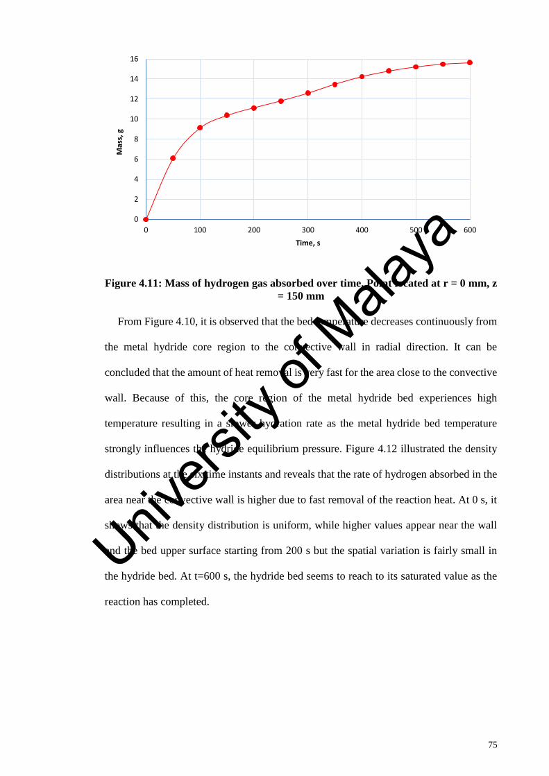
75
Figure 4.11: Mass of hydrogen gas absorbed over time. Point located at r = 0 mm, z
= 150 mm
From Figure 4.10, it is observed that the bed temperature decreases continuously from
the metal hydride core region to the convective wall in radial direction. It can be
concluded that the amount of heat removal is very fast for the area close to the convective
wall. Because of this, the core region of the metal hydride bed experiences high
temperature resulting in a slower hydration rate as the metal hydride bed temperature
strongly influences the hydride equilibrium pressure. Figure 4.12 illustrated the density
distributions at the six time instants and reveals that the rate of hydrogen absorbed in the
area near the convective wall is higher due to fast removal of the reaction heat. At 0 s, it
shows that the density distribution is uniform, while higher values appear near the wall
and the bed upper surface starting from 200 s but the spatial variation is fairly small in
the hydride bed. At t=600 s, the hydride bed seems to reach to its saturated value as the
reaction has completed.
0
2
4
6
8
10
12
14
16
0 100 200 300 400 500 600
Mas
s, g
Time, s
Univers
ity of
Mala
ya
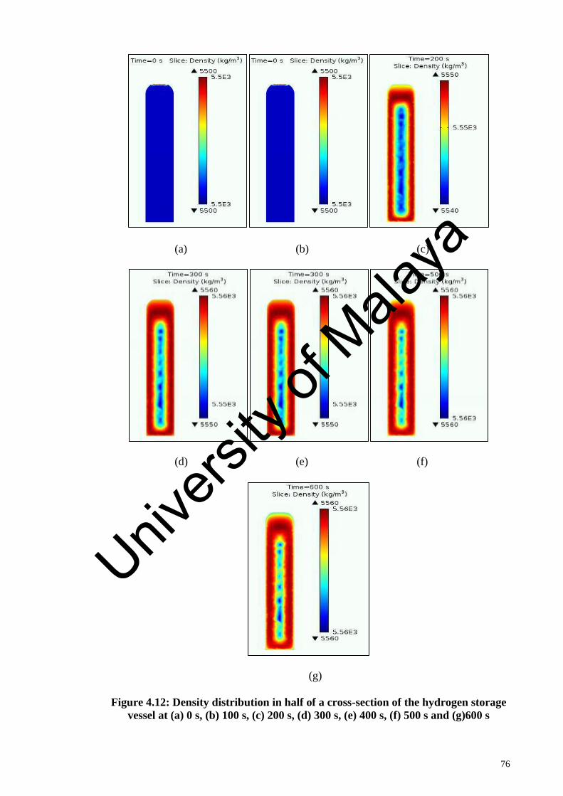
76
(a) (b) (c)
(d) (e) (f)
(g)
Figure 4.12: Density distribution in half of a cross-section of the hydrogen storage
vessel at (a) 0 s, (b) 100 s, (c) 200 s, (d) 300 s, (e) 400 s, (f) 500 s and (g)600 s
Univers
ity of
Mala
ya

77
4.5 Validation of Actual Simulation
As proposed in Section 3.4, the actual simulation results from Section 4.4.2 are being
validated with the prior experiment data collected from Hydrogen Fuel Cell laboratory of
Universiti Malaya (UM). The objective is not to match exactly the values acquired in both
methods but to get the same trend and the same orders of magnitude.
4.5.1 Temperature
A comparison between simulation and experimental data of metal hydride temperature
evolution is demonstrated in Figure 4.13. As can be observed, the experimental and
simulation results match closely having small deviations which is acceptable given the
lack of information about the material’s properties. Although there is some error between
the simulation and the experimental data, the predictions match the reported data quite
well. It is not clear whether the discrepancies between the experimental and the numerical
data are due to experimental issues or minor deficiencies during model implementation
in COMSOL.
Figure 4.13: Temperature comparison between simulation and experimental data
at point r = 0 mm, z = 322 mm
24
26
28
30
32
34
36
0 100 200 300 400 500 600
Tem
pe
ratu
re, o
C
Time, s
Simulation
ExperimentUnivers
ity of
Mala
ya

78
Table 4.4: Temperature comparison between simulation and experimental data at
point r = 0 mm, z = 322 mm
Time (s) Temperature (g) Deviation
(%) Simulation Experimental
0 24.8019 25.0000 0.79
50 33.2897 34.0929 2.36
100 33.9015 34.1861 0.83
150 34.2027 34.2145 0.03
200 34.2220 34.2119 0.03
250 34.2729 34.2200 0.15
300 34.3887 34.1445 0.72
350 34.4077 34.2057 0.59
400 34.2526 34.1811 0.21
450 33.8024 34.2109 1.19
500 33.6922 34.1976 1.48
550 33.5125 34.2233 2.08
600 33.3601 34.1987 2.45
4.5.2 Mass of Hydrogen Absorbed
In Figure 4.14, a comparison between experimental and simulation results based on
the hydrogen mass absorbed can be noticed. It can be seen that the simulation and the
experimental data matches closely having small deviations with the percentages varied
from 0.0~1.2%. With the decay in temperature being linear, and since the heat transfer
coefficient is constant, the rate of heat addition (hydrogen absorption) must also be
constant. This is easily seen in the Figure 4.9 since the concentration increases in a linear
fashion after the initial opening of the valve. If the experiment was continued it would be
expected that the concentration would begin to asymptote as it approaches its
concentration limit and the temperature would begin to decrease in a nonlinear fashion. Univ
ersity
of M
alaya

79
Figure 4.14: Comparison of hydrogen mass absorbed between simulation and
experimental data at point r = 0 mm, z = 150 mm
Table 4.5: Comparison of hydrogen mass absorbed between simulation and
experimental data at point r = 0 mm, z = 150 mm
Time (s) Mass (g) Deviation
(%) Simulation Experiment
0 0.0002 0.0000 0.00
50 6.0991 7.7710 21.51
100 9.1542 9.2090 0.60
150 10.4032 10.3160 0.85
200 11.1065 11.2420 1.21
250 11.7996 12.0330 1.94
300 12.6115 12.7120 0.79
350 13.4740 13.3340 1.05
400 14.2449 13.9020 2.47
450 14.8236 14.4390 2.66
500 15.2287 14.9610 1.79
550 15.4945 15.3720 0.80
600 15.6589 15.8210 1.02
4.6 Sensitivity Analysis
After validating the actual simulation with experimental results, the parametric studies
using computational simulation on variation of small and major influence parameters
such as porosity (ε), permeability (𝐾), metal thermal conductivity (𝑘𝑚), hydrogen
absorption constant on metal (c𝑎), activation energy (𝐸𝑎) and heat transfer coefficient (ℎ)
0
2
4
6
8
10
12
14
16
0 100 200 300 400 500 600
Mas
s, g
Time, s
Simulation
Experiment
Univers
ity of
Mala
ya

80
are conducted. The purpose of this study is to observe the effect of different metal
hydrides properties on the behavior of the hydrogen storage system during the absorption
process especially in terms of mass and heat transfer. The results are illustrated as the
followings.
During analyzing the properties of the material, it is noticed that there are a few
parameters that greatly influence the metal hydrides performance by either reducing the
absorption time or decreasing the maximum temperature. However, there are also some
parameters that do not hold a noticeable effect on the simulation results.
4.6.1 Porosity (ε)
Porosity are one of the parameter that may vary depending on the coating and
compaction process of the storage material, which finally morphed into pellets. The void
fraction or porosity simply represents the void spaces in the pellets since they are formed
by compaction of particles. For the same amount of material, the porosity of the pellets
would vary depending on the compaction pressure applied to form the compacts.
Assuming that other properties remain the same, increasing porosity would actually
increase permeability of hydrogen through the porous space. Thus, the particles will
easily come into contact with the hydrogen gas during the sorption process, which would
eventually accelerate the reaction process and help reach saturation relatively fast. This
is shown in Figure 4.15, where with the increasing of porosity, hydrogen concentration
in the hydride also increases at relatively faster rate during the absorption process.
Meanwhile, Figure 4.16 shows temperature evolution of metal hydride canister over time
at different porosity values. At the beginning, there is sharp growth of temperature curve
reaching a peak of maximum temperature for every porosity values and then diminished
slowly leading to a temperature plateau. Although the maximum temperature reached by
each values were different, the final temperature level is kept more or less similar as the
Univers
ity of
Mala
ya

81
heat produced by exothermic reaction and heat removal due to convection with exterior
air are in equilibrium with similar rate of dissipation. As the volume of the canister is
fixed, objectively when porosity is high (ε= 0.8), the amount of hydrogen stored is lower
as there is less available metal volume within the canister for the hydrogen to be absorbed.
Therefore, the absorption process finish faster and the temperature reduced until it reaches
ambient temperature sooner. Otherwise, when the porosity is low (ε= 0.1), the absorption
process is slower, as there is more metal inside the canister and so more time for hydrogen
to completely fill up. Generally, it can be useful in designing a hydrogen storage system
on how the porosity can influence the metal hydride behavior, with a trade-off between
charge time and storage capacity.
Figure 4.15: Density of metal hydride over time at different porosity values. Point
located at r = 0 mm, z = 150 mm
5490
5500
5510
5520
5530
5540
5550
5560
5570
0 100 200 300 400 500 600
De
nsi
ty, k
g/m
3
Time, s
Ɛ=0.1
Ɛ=0.3
Ɛ=0.5
Ɛ=0.65
Ɛ=0.8
Univers
ity of
Mala
ya

82
Figure 4.16: Temperature of metal hydride canister over time at different porosity
values. Point located r = 33 mm, z = 150 mm
4.6.2 Permeability
The effect of permeability on the density and temperature distribution of metal hydride
canister are shown Figure 4.17 and 4.18. It can be observed that there is not much
deviation for the metal hydrides density and temperature values with different values of
permeability. However, the permeability does influence the results, since this parameter
controls the mass transport. When the permeability decreases, hydrogen gas velocity
through matrix solid reduces, on the basis of Darcy’s law, increasing saturation time. As
it can be seen, for permeability below 1 m2, the system shows a decrease of performance
compared to permeability value higher than 1 m2.
20
25
30
35
40
45
0 100 200 300 400 500 600
Tem
pe
ratu
re, o
C
Time, s
Ɛ=0.1
Ɛ=0.3
Ɛ=0.5
Ɛ=0.65
Ɛ=0.8
Univers
ity of
Mala
ya

83
Figure 4.17: Density of metal hydride over time at different permeability values.
Point located at r = 0 mm, z = 150 mm
Figure 4.18: Temperature of metal hydride canister over time at different
permeability values. Point located r = 33 mm, z = 150 mm
4.6.3 Thermal Conductivity (𝑘𝑚)
The effect of varying thermal conductivity of the pellets on the density and temperature
of metal hydride are displayed in Figure 4.19 and 4.20. The evolution of density for
different values of effective thermal conductivity of the material can be seen in Figure
4.19. It is observed that increasing the thermal conductivity value accelerates the reaction
5490
5500
5510
5520
5530
5540
5550
5560
5570
0 100 200 300 400 500 600
De
nsi
ty, k
g/m
3
Time, s
K=1E-10
K=1E-8
K=1E-5
K=1E-3
K=1
0
10
20
30
40
50
0 100 200 300 400 500 600
Tem
pe
ratu
re, o
C
Time, s
K=1E-10
K=1E-8
K=1E-5
K=1E-3
K=1
Univers
ity of
Mala
ya

84
kinetics hence rapid absorption of hydrogen. This is because better heat transmission in
the hydride bed
It can be seen in Figure 4.20, that for a highly conductive hydride, the heat of reaction
is transported to the environment faster result in lower final bed temperature. Although at
the beginning, the maximum temperature reached for 𝑘𝑚 =10 W/m.K and 𝑘𝑚 = 6.5
W/m. K is higher compared to others due to faster absorption reaction rate, the
temperature quickly slows down as the concentrations becomes saturated, and the heat
generated during the reaction process is extracted faster because of better thermal
conductivity of the metal hydrides material.
Therefore, it is proven that the improved thermal conductivity of the metal would
ensure better heat transmission rate, which eventually translates to faster reaction rate and
hence swifter actuation. Thermal conductivity is sensitive to chemical process duration
which with both copper encapsulation and compaction to pellet process which can
improve overall thermal conductivity of the metal hydrides material. It can be concluded
that a conductivity of 6.5 W/m. K is the best for this system as it provides fastest charging
time at the lowest final hydride canister temperature.
5490
5500
5510
5520
5530
5540
5550
5560
5570
0 100 200 300 400 500 600
De
nsi
ty, k
g/m
3
Time, s
km=0.1
km=1
km=1.6
km=6.5
km=10
Univers
ity of
Mala
ya
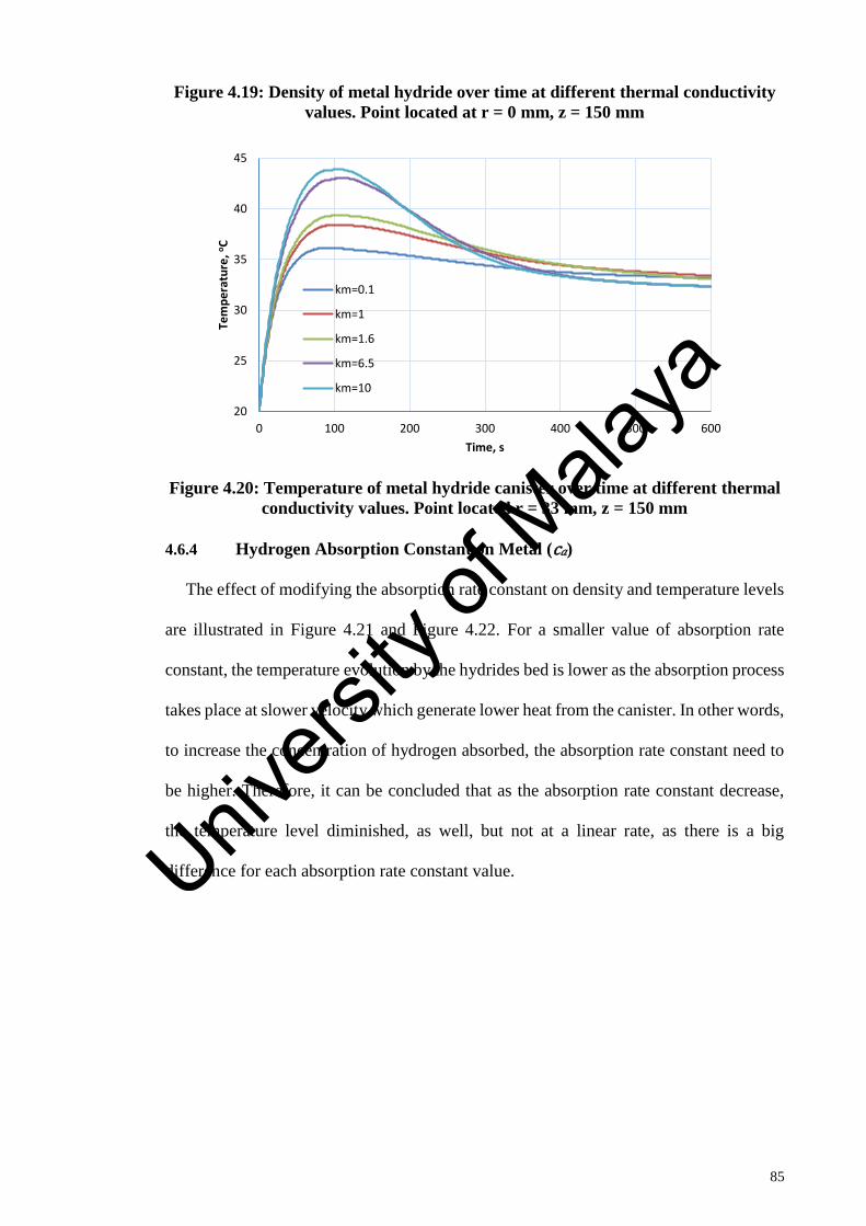
85
Figure 4.19: Density of metal hydride over time at different thermal conductivity
values. Point located at r = 0 mm, z = 150 mm
Figure 4.20: Temperature of metal hydride canister over time at different thermal
conductivity values. Point located r = 33 mm, z = 150 mm
4.6.4 Hydrogen Absorption Constant on Metal (c𝑎)
The effect of modifying the absorption rate constant on density and temperature levels
are illustrated in Figure 4.21 and Figure 4.22. For a smaller value of absorption rate
constant, the temperature evolution by the hydrides bed is lower as the absorption process
takes place at slower velocity which generate lower heat from the canister. In other words,
to increase the concentration of hydrogen absorbed, the absorption rate constant need to
be higher. Therefore, it can be concluded that as the absorption rate constant decrease,
the temperature level diminished, as well, but not at a linear rate, as there is a big
difference for each absorption rate constant value.
20
25
30
35
40
45
0 100 200 300 400 500 600
Tem
pe
ratu
re, o
C
Time, s
km=0.1
km=1
km=1.6
km=6.5
km=10
Univers
ity of
Mala
ya

86
Figure 4.21: Density of metal hydride over time at absorption rate constant values.
Point located at r = 0 mm, z = 150 mm
Figure 4.22: Temperature of metal hydride canister over time at different
absorption rate constant values. Point located r = 33 mm, z = 150 mm
4.6.5 Activation Energy (𝐸𝑎)
For a very high value of activation energy, there is no noticeable distinct values in the
density and temperature of the metal hydride bed as the density and temperature values
for 𝐸𝑎≥ 50000 and 𝐸𝑎≥ 100000 is the same. Meanwhile, when the activation energy is
low a visible difference in the density and temperature evolution is observed. The
different effect of different range of activation energy value is due to the obstacle to start
5490
5500
5510
5520
5530
5540
5550
5560
5570
5580
0 100 200 300 400 500 600
De
nsi
ty, k
g/m
3
Time, s
Ca=1
Ca=10
Ca=50
Ca=100
Ca=305
20
25
30
35
40
45
0 100 200 300 400 500 600
Tem
pe
ratu
re, o
C
Time, s
Ca=1
Ca=10
Ca=50
Ca=100
Ca=305
Univers
ity of
Mala
ya

87
any absorption reaction when the activation energy is too high, as seen in Figure 4.23 and
Figure 4.24. It is even more difficult to start the absorption when the required heat is not
being supplied. For this system, an activation energy of 35000 kg/ m3 and above are
unfavorable. However, it can also been observed that at activation energy of 20000
kg/ m3, the density level fluctuate greatly due to the system become unstable at too low
activation energy.
Figure 4.23: Density of metal hydride over time at different activation energy
values. Point located at r = 0 mm, z = 150 mm
Figure 4.24: Temperature of metal hydride canister over time at different
activation energy values. Point located r = 33 mm, z = 150 mm
5490
5500
5510
5520
5530
5540
5550
5560
5570
0 100 200 300 400 500 600
De
nsi
ty, k
g/m
3
Time, s
Ea=20000
Ea=28000
Ea=35000
Ea=50000
Ea=100000
20
25
30
35
40
45
50
0 100 200 300 400 500 600
Tem
pe
ratu
re, o
C
Time, s
Ea=20000
Ea=28000
Ea=35000
Ea=50000
Ea=100000Univers
ity of
Mala
ya

88
4.6.6 Heat Transfer Coefficient (ℎ)
Absorption reaction can occurs faster due to the heat transfer coefficient. This is
because heat transfer coefficient determines the rate of heat removal from the metal
hydride canister and allows a faster hydrogen mass flow rate into the canister. To study
the effect of heat transfer coefficient on the hydrogen absorption rate, the value of heat
transfer coefficient is varied from 10 to 1000 W/m2. K by keeping the other operating
parameters as constant. As observed, Figure 4.25 and 4.26 show the effect of different
heat transfer coefficient on metal hydrides canister temperature and density distribution
for 600 s.
Figure 4.25: Density of metal hydride over time at different heat transfer
coefficient values. Point located at r = 0 mm, z = 150 mm
5490
5500
5510
5520
5530
5540
5550
5560
5570
0 100 200 300 400 500 600
De
nsi
ty, k
g/m
3
Time, s
h = 10
h = 50
h = 200
h = 500
h = 1000
Univers
ity of
Mala
ya

89
Figure 4.26: Temperature of metal hydride canister over time at different heat
transfer coefficient values. Point located r = 33 mm, z = 150 mm
The heat transfer coefficient plays a significant role during absorption process of
hydrogen. It is observed from Figure 4.26 that for heat transfer coefficient of 1000W/m2
K, the reaction bed temperature reaches the canister initial temperature faster, while for
the other cases it takes more time. However, as it is noticed from Figure 4.25 that the
amount of hydrogen absorbed at different overall heat transfer coefficients is similar
without much deviation. Hence, one can conclude that the selection of overall heat
transfer coefficient should be based on the optimum value of heat transfer coefficient and
not too high as it not give much effect to the hydride density.
4.7 Effect of operating condition
An optimization of the system has been carried out for the operating conditions and
thickness of the metal hydrides canister.
4.7.1 Charging pressure
Charging pressure gives significant effect on the absorption process of metal hydride
as the difference between equilibrium pressure and pressure within the hydride canister
controls the process which effecting the hydration rates. To study the effect of varying
0
10
20
30
40
50
60
70
80
0 100 200 300 400 500 600
Tem
pe
ratu
re, o
C
Time, s
h = 10
h = 50
h = 200
h = 500
h = 1000
Univers
ity of
Mala
ya

90
charging pressure on the hydrides bed density and temperature, numerical simulation is
carried out at five different charging pressures from 10 to 50 bar by keeping the
temperature constant. In Figure 4.27 and 4.28, the effect of hydrogen gas pressure on the
temperature and density distribution during hydrogen absorption process are shown.
Figure 4.27: Figure 4.27: Density of metal hydride over time at different charging
pressure values. Point located at r = 0 mm, z = 150 mm
Figure 4.28: Temperature of metal hydride canister over time at different charging
pressure values. Point located r = 33 mm, z = 150 mm
5490
5500
5510
5520
5530
5540
5550
5560
5570
0 100 200 300 400 500 600
De
nsi
ty, k
g/m
3
Time, s
p=10
p=20
p=30
p=40
p=50
0
5
10
15
20
25
30
35
40
45
0 100 200 300 400 500 600
Tem
pe
ratu
re, o
C
Time, s
p=10
p=20
p=30
p=40
p=50Univ
ersity
of M
alaya
91
As seen in Figure 4.27, a high charging pressure can reduce the time taken for
hydrogen gas to completely fill the metal hydrides bed and reaches the saturated density.
The increase in the hydrogen absorbent capacity with increasing the supply pressure is
due to plateau slope. It can be observed that with high supply pressure, the hydrogen
charging time becomes shorter, but there is not much different in the maximum value of
hydrogen absorbed except when the charging pressure at 10 bar. So it can be concluded
that charging pressure influences the charging time of the hydrides system.
Figure 4.28 shows the temperature evolution of metal hydride bed at different charging
pressures during the absorption process. As it can be observed, the temperature value rise
sharply at about 50 s in the beginning for a given charging pressure. However, after
achieving its maximum temperature, the temperature decreases steadily and approaches
the ambient temperature. The sudden increase in the temperature at the initial stage is due
to rapid absorption rate of hydrogen into metal hydrides canister. Figure 4.28 also
illustrates that for this system, the higher the charging pressure value is, the higher the
rise in bed temperature. This is due to the bigger differences between the charging
pressure and the equilibrium as well as higher generation of heat. Therefore, improvement
in the heat transfer characteristic of the hydrides canister through optimum design can be
done in order to reduce the heat generation. The improvement can be done through the
development of innovative hydride beds. For example, a new metal hydride bed should
be developed with the adoption of graphite matrix or metallic foam, adequate hydrogen
porosity and high equivalent thermal conductivity as well as heat transfer coefficient.
4.7.2 Bed Temperature
The density and temperature of metal hydrides bed at different initial bed temperatures
are shown in Figures 4.29 and 4.30.
Univers
ity of
Mala
ya

92
Figure 4.29: Density of metal hydride over time at different bed temperature
values. Point located at r = 0 mm, z = 150 mm
Figure 4.30: Temperature of metal hydride canister over time at different bed
temperature values. Point located r = 33 mm, z = 150 mm
As observed in Figure 4.30, increase in initial bed temperature increases the maximum
temperature achieved for each given bed temperature value. However, after the peak, the
temperature starting to reduce to initial canister temperature and reach the ambient
temperature approximately at a similar time as the hydrides density starting to become
saturated. Besides, it can be seen in Figure 4.29 that the density of metal hydride also
increases faster with higher value of initial bed temperature. This is due to the kinetics of
5500
5510
5520
5530
5540
5550
5560
5570
0 100 200 300 400 500 600
De
nsi
ty, k
g/m
3
Time, s
T=20
T=33
T=40
T=50
T=55
0
10
20
30
40
50
60
0 100 200 300 400 500 600
Tem
pe
ratu
re, o
C
Time, s
T=20
T=33
T=40
T=50
T=55
Univers
ity of
Mala
ya

93
the metal hydrides material which is faster at higher temperature, which indicates faster
absorption rates of hydrogen and reduces with charging time. Thus, it can be concluded
that the increase in the hydride bed temperature will increase the maximum temperature
and decrease the charging time of the hydrides system.
Univers
ity of
Mala
ya

94
CHAPTER 5: CONCLUSION & RECOMMENDATION
This chapter will conclude the main findings in this thesis and discuss the
recommendations for future work.
In this chapter a three-dimensional mathematical model is presented for describing the
absorption processes that take place in porous metal hydride
5.1 Conclusion
A three dimensional mathematical model which represent the principle of mass,
momentum and energy conversation as well as absorption kinetics is developed to be used
in the simulation of hydrogen absorption process within metal hydride canister. The
validity of the mathematical model is first tested by comparing it with other author’s
published work, which later achieved a good agreement between all the data.
The validated model then has been implemented in COMSOL Multiphysics software
using an actual metal hydrides canister which utilizes the finite element method to solve
the governing equations. The governing equations are numerically solved and the
calculated results are compared with the prior experimental data. The simulation and
experimental results show agreement with each other having small deviation between
0.0~2.5%.
The simulated actual metal hydrides canister is then be applied to study the behavior
of metal hydride canister system. The objectives of the study is to achieve a better metal
hydride system while reducing the amount of time-consuming experiments required since
simulation is robust and has fast solving time. For this purpose, parametric studies have
been conducted. The parametric studies analyze the effect of different metal hydrides
properties on the behavior of metal hydrides system in term of heat and mass transfer.
Univers
ity of
Mala
ya

95
The sensitivity analysis indicated that the effective thermal conductivity was the most
sensitive parameters for this system while other parameters such as porosity, permeability
and heat transfer coefficient carried little effect on the system. However, the permeability
does influence the results, since this parameter controls the mass transport and the effect
of the porosity on the metal hydride behavior which can be useful in designing a hydrogen
storage system with the study of the porosity can influence on the metal hydride behavior,
considering a trade-off between charge time and storage capacity. It can also be observed
that at a very high value of activation energy there is no noticeable difference in the
density and temperature whereas, in order to increase the concentration of hydrogen
absorbed, the absorption rate constant needs to be higher but not exceed the optimum
value.
Furthermore, the improvement in the thermal conductivity of the metal would ensure
better heat transmission rate, which eventually translates to a faster reaction rate and
hence swifter actuation. . It can be concluded that a conductivity of 6.5 W/m. K is the
best for this system as it provides the fastest charging time with the lowest final hydride
canister temperature. For heat transfer coefficient, one can conclude that the selection of
overall heat transfer coefficient should be based on the optimum value of heat transfer
coefficient as increasing of it not give much effect to the hydride density. This is because
the heat transfer by convection not a dominant phenomenon during the absorption
process.
Lastly, considering the operating condition, it can be concluded that the high charging
pressure can reduce the time taken for hydrogen gas to completely fill the metal hydrides
bed and the higher the charging pressure value, the higher the rise in bed temperature.
Besides, it also can be concluded that increase in the hydride bed temperature will
Univers
ity of
Mala
ya

96
increase the maximum temperature and decrease the charging time of the hydrides
system.
5.2 Recommendation
The following suggestion are either plan for the project in the future that are considered
to be beyond the scope of this work, or recommendations for future researchers who are
planning to study in more details the metal hydride hydrogen storage systems:
1. The major focus for the future can be to develop a mathematical model for heat
and mass transfer modelling that will be able to describe kinetics of other complex
materials. For now, the developed mathematical model is only applicable to
describe the behavior of simple type of material.
2. Further research efforts should be focused on the improvement of the thermal
exchange for the storage canister through the development of innovative hydride
beds. For example, a new metal hydride bed should be developed with the
adoption of graphite matrix or metallic foam, adequate hydrogen porosity and
high equivalent thermal conductivity as well as heat transfer coefficient.
3. Lastly, optimum design models for metal hydride storage units is required in order
for the metal hydride technology to compete with existence compressed and liquid
hydrogen storage which can satisfy the goal for public and efficient energy
storage.Univers
ity of
Mala
ya

97
REFERENCES
(Aburto, A., & Orgaz, E. (2007). Ab initio structural and electronic investigation of
magnetic RNiSn (R=La,Ce,Pr,Nd) intermetallics and their hydrides. Physical
Review B, 75(4), 045130.
Aceves, S. M., Berry, G. D., Martinez-Frias, J., & Espinosa-Loza, F. (2006). Vehicular
storage of hydrogen in insulated pressure vessels. International Journal of
Hydrogen Energy, 31(15), 2274-2283.
Aceves, S. M., Petitpas, G., Espinosa-Loza, F., Matthews, M. J., & Ledesma-Orozco, E.
(2013). Safe, long range, inexpensive and rapidly refuelable hydrogen vehicles
with cryogenic pressure vessels. International Journal of Hydrogen Energy,
38(5), 2480-2489.
Agrawal, R., Offutt, M., & Ramage, M. P. (2005). Hydrogen economy - an opportunity
for chemical engineers? AIChE Journal, 51(6), 1582-1589.
Akbarzadeh, A. R., Wolverton, C., & Ozolins, V. (2009). First-principles determination
of crystal structures, phase stability, and reaction thermodynamics in the Li-Mg-
Al-H hydrogen storage system. Physical Review B, 79(18), 184102.
Albanese, E., Kalantzopoulos, G. N., Vitillo, J. G., Pinatel, E., Civalleri, B., Deledda, S.,
. . . Baricco, M. (2013). Theoretical and experimental study on Mg(BH4)2–
Zn(BH4)2 mixed borohydrides. Journal of Alloys and Compounds, 580,
Supplement 1(0), S282-S286.
Aldas, K., Mat, M. D., & Kaplan, Y. (2002). A three-dimensional mathematical model
for absorption in a metal hydride bed. International Journal of Hydrogen Energy,
27(10), 1049-1056.
Ananthachar, V., & Duffy, J. J. (2005). Efficiencies of hydrogen storage systems onboard
fuel cell vehicles. Solar Energy, 78(5), 687-694.
Andreasen, A. (2008). Hydrogenation properties of Mg–Al alloys. International Journal
of Hydrogen Energy, 33(24), 7489-7497.
Andrews, J., & Shabani, B. (2012). Re-envisioning the role of hydrogen in a sustainable
energy economy. International Journal of Hydrogen Energy, 37(2), 1184-1203.
Arnbjerg, L. M., Ravnsbæk, D. B., Filinchuk, Y., Vang, R. T., Cerenius, Y., Besenbacher,
F., . . . Jensen, T. R. (2009). Structure and Dynamics for LiBH4−LiCl Solid
Solutions. Chemistry of Materials, 21(24), 5772-5782.
Ashraful, A. M., Masjuki, H. H., Kalam, M. A., Rizwanul Fattah, I. M., Imtenan, S.,
Shahir, S. A., & Mobarak, H. M. (2014). Production and comparison of fuel
properties, engine performance, and emission characteristics of biodiesel from
various non-edible vegetable oils: A review. Energy Conversion and
Management, 80, 202-228.
Univers
ity of
Mala
ya

98
Baladincz, P., & Hancsók, J. (2015). Fuel from waste animal fats. Chemical Engineering
Journal, 282, 152-160.
Ball, M., & Wietschel, M. (2009). The future of hydrogen – opportunities and challenges.
International Journal of Hydrogen Energy, 34(2), 615-627.
Banković-Ilić, I. B., Stojković, I. J., Stamenković, O. S., Veljkovic, V. B., & Hung, Y.-
T. (2014). Waste animal fats as feedstocks for biodiesel production. Renewable
and Sustainable Energy Reviews, 32, 238-254.
Barkhordarian, G., Klassen, T., Dornheim, M., & Bormann, R. (2007). Unexpected
kinetic effect of MgB2 in reactive hydride composites containing complex
borohydrides. Journal of Alloys and Compounds, 440(1–2), L18-L21.
Blackman, J. M., Patrick, J. W., Arenillas, A., Shi, W., & Snape, C. E. (2006). Activation
of carbon nanofibres for hydrogen storage. Carbon, 44(8), 1376-1385.
Bogdanović, B., Felderhoff, M., & Streukens, G. (2009). Hydrogen storage in complex
metal hydrides. Journal of the Serbian Chemical Society, 74(2), 183-196.
Borzone, E. M., Baruj, A., Blanco, M. V., & Meyer, G. O. (2013). Dynamic
measurements of hydrogen reaction with LaNi5−xSnx alloys. International
Journal of Hydrogen Energy, 38(18), 7335-7343.
Brouwer, J. (2010). On the role of fuel cells and hydrogen in a more sustainable and
renewable energy future. Current Applied Physics, 10(2, Supplement), S9-S17.
Busqué Somacarrera, R. (2015). Metal hydride state of charge estimator. Development
and experimental validation of the hydrogen storage system model.
Choudhury, P., Srinivasan, S. S., Bhethanabotla, V. R., Goswami, Y., McGrath, K., &
Stefanakos, E. K. (2009). Nano-Ni doped Li–Mn–B–H system as a new hydrogen
storage candidate. International Journal of Hydrogen Energy, 34(15), 6325-6334.
Cipriani, G., Di Dio, V., Genduso, F., La Cascia, D., Liga, R., Miceli, R., & Ricco
Galluzzo, G. (2014). Perspective on hydrogen energy carrier and its automotive
applications. International Journal of Hydrogen Energy, 39(16), 8482-8494.
Ćirić, K. D., Kocjan, A., Gradišek, A., Koteski, V. J., Kalijadis, A. M., Ivanovski, V. N.,
. . . Stojić, D. L. (2012). A study on crystal structure, bonding and hydriding
properties of Ti–Fe–Ni intermetallics–Behind substitution of iron by nickel.
International Journal of Hydrogen Energy, 37(10), 8408-8417.
de Castro, J. F. R., Santos, S. F., Costa, A. L. M., Yavari, A. R., Botta F, W. J., &
Ishikawa, T. T. (2004). Structural characterization and dehydrogenation behavior
of Mg–5 at.%Nb nano-composite processed by reactive milling. Journal of Alloys
and Compounds, 376(1–2), 251-256.
Demirbas, A. (2007). Storage and Transportation Opportunities of Hydrogen. Energy
Sources, Part B: Economics, Planning, and Policy, 2(3), 287-295.
Univers
ity of
Mala
ya

99
Denys, R. V., Riabov, B., Yartys, V. A., Delaplane, R. G., & Sato, M. (2007). Hydrogen
storage properties and structure of La1−xMgx(Ni1−yMny)3 intermetallics and
their hydrides. Journal of Alloys and Compounds, 446–447(0), 166-172.
Dornheim, M., Doppiu, S., Barkhordarian, G., Boesenberg, U., Klassen, T., Gutfleisch,
O., & Bormann, R. (2007). Hydrogen storage in magnesium-based hydrides and
hydride composites. Scripta Materialia, 56(10), 841-846.
Eberle, U., Arnold, G., & von Helmolt, R. (2006). Hydrogen storage in metal–hydrogen
systems and their derivatives. Journal of Power Sources, 154(2), 456-460.
Ehret, O., & Bonhoff, K. (2015). Hydrogen as a fuel and energy storage: Success factors
for the German Energiewende. International Journal of Hydrogen Energy,
40(15), 5526-5533.
Endo, N., Saitoh, H., Machida, A., & Katayama, Y. (2013). Formation of BCC TiFe
hydride under high hydrogen pressure. International Journal of Hydrogen
Energy, 38(16), 6726-6729.
Falahati, H., & Barz, D. P. J. (2013). Evaluation of hydrogen sorption models for AB5-
type metal alloys by employing a gravimetric technique. International Journal of
Hydrogen Energy, 38(21), 8838-8851.
Freni, A., Cipitì, F., & Cacciola, G. (2009). Finite element-based simulation of a metal
hydride-based hydrogen storage tank. International Journal of Hydrogen Energy,
34(20), 8574-8582.
Garland, N. L., Papageorgopoulos, D. C., & Stanford, J. M. (2012). Hydrogen and Fuel
Cell Technology: Progress, Challenges, and Future Directions. Energy Procedia,
28, 2-11.
Gasiorowski, A., Iwasieczko, W., Skoryna, D., Drulis, H., & Jurczyk, M. (2004).
Hydriding properties of nanocrystalline Mg2−xMxNi alloys synthesized by
mechanical alloying (M=Mn, Al). Journal of Alloys and Compounds, 364(1–2),
283-288.
Georgakis, M., Stavropoulos, G., & Sakellaropoulos, G. P. (2007). Predictions for
molecular hydrogen adsorption in microporous carbons via molecular dynamics
simulations and a suggestion for a hydrogen storage medium. International
Journal of Hydrogen Energy, 32(15), 3465-3470.
George, L., & Saxena, S. K. (2010). Structural stability of metal hydrides, alanates and
borohydrides of alkali and alkali- earth elements: A review. International Journal
of Hydrogen Energy, 35(11), 5454-5470.
Georgiadis, M. C., Kikkinides, E. S., Makridis, S. S., Kouramas, K., & Pistikopoulos, E.
N. (2009). Design and optimization of advanced materials and processes for
efficient hydrogen storage. Computers & Chemical Engineering, 33(5), 1077-
1090.
Gross, K. J., Sandrock, G., & Thomas, G. J. (2002). Dynamic in situ X-ray diffraction of
catalyzed alanates. Journal of Alloys and Compounds, 330–332(0), 691-695.
Univers
ity of
Mala
ya

100
He, G., Jiao, L.-F., Yuan, H.-T., Zhang, Y.-Y., & Wang, Y.-J. (2008). Preparation and
electrochemical properties of MgNi–MB (M = Co, Ti) composite
alloys. Journal of Alloys and Compounds, 450(1–2), 375-379.
Ho, S. H., & Rahman, M. M. (2008). Three-dimensional analysis for liquid hydrogen in
a cryogenic storage tank with heat pipe–pump system. Cryogenics, 48(1-2), 31-
41.
Hoel, M., & Kverndokk, S. (1996). Depletion of fossil fuels and the impacts of global
warming. Resource and Energy Economics, 18(2), 115-136.
Hong, S.-H., & Song, M. Y. (2013). Hydrogen desorption and absorption properties of
Pd and MgO or nano-sized Ni-added MgH2 + LiBH4 composites.
Materials Research Bulletin, 48(9), 3453-3458.
Huang, Z. G., Guo, Z. P., Calka, A., Wexler, D., Lukey, C., & Liu, H. K. (2006). Effects
of iron oxide (Fe2O3, Fe3O4) on hydrogen storage properties of Mg-based
composites. Journal of Alloys and Compounds, 422(1–2), 299-304.
Hwang, H. T., Al-Kukhun, A., & Varma, A. (2010). Hydrogen for Vehicle Applications
from Hydrothermolysis of Ammonia Borane: Hydrogen Yield, Thermal
Characteristics, and Ammonia Formation. Industrial & Engineering Chemistry
Research, 49(21), 10994-11000.
Ichikawa, T., Hanada, N., Isobe, S., Leng, H., & Fujii, H. (2005). Composite Materials
based on Light Elements for Hydrogen Storage. MATERIALS TRANSACTIONS,
46(1), 1-14.
Iosub, V., Matsunaga, T., Tange, K., & Ishikiriyama, M. (2009). Direct synthesis of
Mg(AlH4)2 and CaAlH5 crystalline compounds by ball milling and their potential
as hydrogen storage materials. International Journal of Hydrogen Energy, 34(2),
906-912.
Islam, M. T., Huda, N., Abdullah, A. B., & Saidur, R. (2018). A comprehensive review
of state-of-the-art concentrating solar power (CSP) technologies: Current status
and research trends. Renewable and Sustainable Energy Reviews, 91, 987-1018.
Issariyakul, T., & Dalai, A. K. (2014). Biodiesel from vegetable oils. Renewable and
Sustainable Energy Reviews, 31, 446-471.
Jain, I. P., Lal, C., & Jain, A. (2010). Hydrogen storage in Mg: A most promising material.
International Journal of Hydrogen Energy, 35(10), 5133-5144.
Jain, R. K., Jain, A., Agarwal, S., Lalla, N. P., Ganesan, V., Phase, D. M., & Jain, I. P.
(2007). Hydrogenation behaviour of Ce-based AB5 intermetallic compounds.
Journal of Alloys and Compounds, 440(1–2), 84-88.
Jemni, A., & Nasrallah, S. B. (1995). Study of two-dimensional heat and mass transfer
during absorption in a metal-hydrogen reactor. International Journal of Hydrogen
Energy, 20(1), 43-52.
Univers
ity of
Mala
ya

101
Jeon, E., & Cho, Y. (2006). Mechanochemical synthesis and thermal decomposition of
zinc borohydride. Journal of Alloys and Compounds, 422(1–2), 273-275.
Kalisvaart, W. P., Harrower, C. T., Haagsma, J., Zahiri, B., Luber, E. J., Ophus, C., . . .
Mitlin, D. (2010). Hydrogen storage in binary and ternary Mg-based alloys: A
comprehensive experimental study. International Journal of Hydrogen Energy,
35(5), 2091-2103.
Kang, X.-D., Luo, J.-H., & Wang, P. (2012). Efficient and highly rapid hydrogen release
from ball-milled 3NH3BH3/MMgH3 (M = Na, K, Rb) mixtures at low
temperatures. International Journal of Hydrogen Energy, 37(5), 4259-4266.
Klindtworth, E., Delidovich, I., & Palkovits, R. (2018). Borohydride in ionic liquids for
tailored hydrogen release. International Journal of Hydrogen Energy, 43(45),
20772-20782.
Kontorovich, A. E., Epov, M. I., & Eder, L. V. (2014). Long-term and medium-term
scenarios and factors in world energy perspectives for the 21st century. Russian
Geology and Geophysics, 55(5–6), 534-543.
Kumar, S., Sonak, S., & Krishnamurthy, N. (2013). Hydrogen solid solution
thermodynamics of V1−xAlx (x: 0, 0.18, 0.37, 0.52) alloys. International Journal
of Hydrogen Energy, 38(23), 9928-9934.
Latroche, M., & Percheron-Guégan, A. (2003). Structural and thermodynamic studies of
some hydride forming RM3-type compounds (R=lanthanide, M=transition metal).
Journal of Alloys and Compounds, 356–357(0), 461-468.
Laversenne, B. B. L. Hydrogen storage using borohydrides Entropy, 184, 183.183-
242.183.
Lee, T. B., & McKee, M. L. (2009). Mechanistic Study of LiNH2BH3 Formation from
(LiH)4 + NH3BH3 and Subsequent Dehydrogenation. Inorganic Chemistry,
48(16), 7564-7575.
Ley, M. B., Jepsen, L. H., Lee, Y.-S., Cho, Y. W., Bellosta von Colbe, J. M., Dornheim,
M., . . . Jensen, T. R. (2014). Complex hydrides for hydrogen storage – new
perspectives. Materials Today, 17(3), 122-128.
Liang, G. (2004). Synthesis and hydrogen storage properties of Mg-based alloys. Journal
of Alloys and Compounds, 370(1–2), 123-128.
Liu, T., Wang, C., & Wu, Y. (2014). Mg-based nanocomposites with improved hydrogen
storage performances. International Journal of Hydrogen Energy, 39(26), 14262-
14274.
López González, E., Isorna Llerena, F., Silva Pérez, M., Rosa Iglesias, F., & Guerra
Macho, J. (2015). Energy evaluation of a solar hydrogen storage facility:
Comparison with other electrical energy storage technologies. International
Journal of Hydrogen Energy, 40(15), 5518-5525.
Univers
ity of
Mala
ya

102
M. Martin, C. Gommel, C. Borkhart, & Fromm, E. (1996). Absorption and desorption
kinetics of hydrogen storage alloys. Journal of Alloys and Compounds, 238(1-2),
193-201.
Ma, L.-J., Jia, J., Wu, H.-S., & Ren, Y. (2013). Ti–η2-(C2H2) and HCC–TiH as high
capacity hydrogen storage media. International Journal of Hydrogen Energy,
38(36), 16185-16192.
Maeda, T., Fuura, T., Matsumoto, I., Kawakami, Y., & Masuda, M. (2013). Cyclic
stability test of AB2 type (Ti, Zr)(Ni, Mn, V, Fe)2.18 for stationary hydrogen
storage in water contaminated hydrogen. Journal of Alloys and Compounds, 580,
Supplement 1(0), S255-S258.
Mao, J. (2011). Light metal hydrides for reversible hydrogen storage applications.
Mao, J., Guo, Z., & Liu, H. (2012). Enhanced hydrogen storage properties of NaAlH 4
co-catalysed with niobium fluoride and single-walled carbon nanotubes. Rsc
Advances, 2(4), 1569-1576.
Marchenko, O. V., & Solomin, S. V. (2015). The future energy: Hydrogen versus
electricity. International Journal of Hydrogen Energy, 40(10), 3801-3805.
Mohr, S. H., Wang, J., Ellem, G., Ward, J., & Giurco, D. (2015). Projection of world
fossil fuels by country. Fuel, 141, 120-135.
Mori, D., & Hirose, K. (2009). Recent challenges of hydrogen storage technologies for
fuel cell vehicles. International Journal of Hydrogen Energy, 34(10), 4569-4574.
Mosher, D. A., Arsenault, S., Tang, X., & Anton, D. L. (2007). Design, fabrication and
testing of NaAlH4 based hydrogen storage systems. Journal of Alloys and
Compounds, 446–447(0), 707-712.
Nakamori, Y., & Orimo, S.-i. (2004). Destabilization of Li-based complex hydrides.
Journal of Alloys and Compounds, 370(1–2), 271-275.
Nam, J., Ko, J., & Ju, H. (2012). Three-dimensional modeling and simulation of hydrogen
absorption in metal hydride hydrogen storage vessels. Applied Energy, 89(1), 164-
175.
Nasrallah, S. B., & Jemni, A. (1997). Heat and mass transfer models in metal-hydrogen
reactor. International Journal of Hydrogen Energy, 22(1), 67-76.
Nath, K., Najafpour, M. M., Voloshin, R. A., Balaghi, S. E., Tyystjärvi, E., Timilsina, R.,
. . . Allakhverdiev, S. I. (2015). Photobiological hydrogen production and artificial
photosynthesis for clean energy: from bio to nanotechnologies. Photosynthesis
Research, 126(2-3), 237-247.
Nickels, E. A., Jones, M. O., David, W. I. F., Johnson, S. R., Lowton, R. L., Sommariva,
M., & Edwards, P. P. (2008). Tuning the Decomposition Temperature in Complex
Hydrides: Synthesis of a Mixed Alkali Metal Borohydride. Angewandte Chemie
International Edition, 47(15), 2817-2819.
Univers
ity of
Mala
ya

103
Okada, M., Kuriiwa, T., Kamegawa, A., & Takamura, H. (2002). Role of intermetallics
in hydrogen storage materials. Materials Science and Engineering: A, 329–
331(0), 305-312.
Orgaz, E. (2001). The electronic structure of the Laves phase intermetallics LnM2 (Ln=Y,
La–Lu, M=Mg, Al) and the LaMg2H7 and CeMg2H7 hydrides. Journal of Alloys
and Compounds, 322(1–2), 45-54.
Orhan, M. F., & Babu, B. S. (2015). Investigation of an integrated hydrogen production
system based on nuclear and renewable energy sources: Comparative evaluation
of hydrogen production options with a regenerative fuel cell system. Energy, 88,
801-820.
Ouyang, L. Z., Cao, Z. J., Yao, L., Wang, H., Liu, J. W., & Zhu, M. (2014). Comparative
investigation on the hydrogenation/dehydrogenation characteristics and hydrogen
storage properties of Mg3Ag and Mg3Y. International Journal of Hydrogen
Energy, 39(25), 13616-13621.
Paggiaro, R., Bénard, P., & Polifke, W. (2010). Cryo-adsorptive hydrogen storage on
activated carbon. I: Thermodynamic analysis of adsorption vessels and
comparison with liquid and compressed gas hydrogen storage. International
Journal of Hydrogen Energy, 35(2), 638-647.
Palewski, T., Tristan, N. V., Drulis, H., & Ćwik, J. (2005). Hydrogenation process of the
Gd3M (M = Ni or Co) intermetallics compound. Journal of Alloys and
Compounds, 404–406(0), 584-587.
Pan, H., Liu, Y., Gao, M., Zhu, Y., & Lei, Y. (2003). The structural and electrochemical
properties of La0.7Mg0.3(Ni0.85Co0.15)x (x=3.0–5.0) hydrogen storage
alloys. International Journal of Hydrogen Energy, 28(11), 1219-1228.
Patil, S. D., & Ram Gopal, M. (2013). Analysis of a metal hydride reactor for hydrogen
storage. International Journal of Hydrogen Energy, 38(2), 942-951.
Ponthieu, M., Fernández, J. F., Cuevas, F., Bodega, J., Ares, J. R., Adeva, P., & Sánchez,
C. (2014). Thermodynamics and reaction pathways of hydrogen sorption in
Mg6(Pd,TM) (TM = Ag, Cu and Ni) pseudo-binary compounds. International
Journal of Hydrogen Energy, 39(32), 18291-18301.
Prigent, J., & Gupta, M. (2007). Ab initio study of the hydrogenation properties of Mg-
based binary and ternary compounds Mg2X (X = Ni, Si) and
YMgNi4. Journal of Alloys and Compounds, 446–447(0), 90-95.
Prigent, J., Joubert, J. M., & Gupta, M. (2012). Modification of the hydrogenation
properties of LaNi5 upon Ni substitution by Rh, Ir, Pt or Au. Journal of Alloys
and Compounds, 511(1), 95-100.
Principi, G., Agresti, F., Maddalena, A., & Lo Russo, S. (2009). The problem of solid
state hydrogen storage. Energy, 34(12), 2087-2091.
Univers
ity of
Mala
ya

104
Ravnsbæk, D., Filinchuk, Y., Cerenius, Y., Jakobsen, H. J., Besenbacher, F., Skibsted, J.,
& Jensen, T. R. (2009). A Series of Mixed-Metal Borohydrides. Angewandte
Chemie International Edition, 48(36), 6659-6663.
Ross, D. K. (2006). Hydrogen storage: The major technological barrier to the
development of hydrogen fuel cell cars. Vacuum, 80(10), 1084-1089.
Sai Raman, S. S., Davidson, D. J., Bobet, J. L., & Srivastava, O. N. (2002). Investigations
on the synthesis, structural and microstructural characterizations of Mg-based
K2PtCl6 type (Mg2FeH6) hydrogen storage material prepared by mechanical
alloying. Journal of Alloys and Compounds, 333(1–2), 282-290.
Sakintuna, B., Lamaridarkrim, F., & Hirscher, M. (2007). Metal hydride materials for
solid hydrogen storage: A review☆. International Journal of Hydrogen Energy,
32(9), 1121-1140.
Satheesh, A., & Muthukumar, P. (2010). Performance investigation of double-stage metal
hydride based heat pump. Applied Thermal Engineering, 30(17–18), 2698-2707.
Schuth, F., Bogdanovic, B., & Felderhoff, M. (2004). Light metal hydrides and complex
hydrides for hydrogen storage. Chemical Communications(20), 2249-2258.
Shao, H., Liu, T., Wang, Y., Xu, H., & Li, X. (2008). Preparation of Mg-based hydrogen
storage materials from metal nanoparticles. Journal of Alloys and Compounds,
465(1–2), 527-533.
Sharma, S., & Ghoshal, S. K. (2015). Hydrogen the future transportation fuel: From
production to applications. Renewable and Sustainable Energy Reviews, 43, 1151-
1158.
Sharma, V. K., & Anil Kumar, E. (2014). Effect of measurement parameters on
thermodynamic properties of La-based metal hydrides. International Journal of
Hydrogen Energy, 39(11), 5888-5898.
Sherif, S. A., Barbir, F., & Veziroglu, T. N. (2005). Towards a Hydrogen Economy. The
Electricity Journal, 18(6), 62-76.
Shinnar, R. (2003). The hydrogen economy, fuel cells, and electric cars. Technology in
Society, 25(4), 455-476.
Smythe, N. C., & Gordon, J. C. (2010). Ammonia Borane as a Hydrogen Carrier:
Dehydrogenation and Regeneration. European Journal of Inorganic Chemistry,
2010(4), 509-521.
Srinivasa Murthy, S., & Anil Kumar, E. (2014). Advanced materials for solid state
hydrogen storage: “Thermal engineering issues”. Applied Thermal Engineering,
72(2), 176-189.
Effects of catalysts doping on the thermal decomposition behavior of Zn(BH4)2.
International Journal of Hydrogen Energy, 33(9), 2268-2272.
Univers
ity of
Mala
ya

105
Srinivasan, S. S., Brinks, H. W., Hauback, B. C., Sun, D., & Jensen, C. M. (2004). Long
term cycling behavior of titanium doped NaAlH4 prepared through solvent
mediated milling of NaH and Al with titanium dopant precursors. Journal of
Alloys and Compounds, 377(1–2), 283-289.
Tang, X., Opalka, S. M., Laube, B. L., Wu, F.-J., Strickler, J. R., & Anton, D. L. (2007).
Hydrogen storage properties of Na–Li–Mg–Al–H complex hydrides. Journal of
Alloys and Compounds, 446–447(0), 228-231.
Thomas, G. J., Gross, K. J., Yang, N. Y. C., & Jensen, C. (2002). Microstructural
characterization of catalyzed NaAlH4. Journal of Alloys and Compounds, 330–
332(0), 702-707.
Tietze, V., & Stolten, D. (2015). Comparison of hydrogen and methane storage by means
of a thermodynamic analysis. International Journal of Hydrogen Energy, 40(35),
11530-11537.
Trevisani, L., Fabbri, M., Negrini, F., & Ribani, P. L. (2007). Advanced energy recovery
systems from liquid hydrogen. Energy Conversion and Management, 48(1), 146-
154.
Truskey, G. A., Yuan, F., & Katz, D. F. (2004). Transport Phenomena in Biological
Systems: Pearson/Prentice Hall.
Varin, R. A., Czujko, T., & Wronski, Z. (2006). Particle size, grain size and γ-MgH 2
effects on the desorption properties of nanocrystalline commercial magnesium
hydride processed by controlled mechanical milling. Nanotechnology, 17(15),
3856.
Vittetoe, A. W., Niemann, M. U., Srinivasan, S. S., McGrath, K., Kumar, A., Goswami,
D. Y., . . . Thomas, S. (2009). Destabilization of LiAlH4 by nanocrystalline
MgH2. International Journal of Hydrogen Energy, 34(5), 2333-2339.
Wang, K., Zhang, J.-G., & He, P. (2013). Theoretical study on the structure and
dehydrogenation mechanism of mixed metal amidoborane, Na[Li(NH2BH3)]2.
Journal of Alloys and Compounds, 581(0), 59-65.
Wang, P., & Kang, X.-d. (2008). Hydrogen-rich boron-containing materials for hydrogen
storage. Dalton Transactions(40), 5400-5413.
Wang, Y., Adroher, X. C., Chen, J., Yang, X. G., & Miller, T. (2009). Three-dimensional
modeling of hydrogen sorption in metal hydride hydrogen storage beds. Journal
of Power Sources, 194(2), 997-1006.
Wang, Y., Zhao, M., & Wang, L. (2009). Effect of La–Mg-based alloy addition on
structure and electrochemical characteristics of Ti0.10 Zr0.15V0.35Cr0.10Ni0.30
hydrogen storage alloy. International Journal of Hydrogen Energy, 34(6), 2646-
2653.
Wiench, J. W., Balema, V. P., Pecharsky, V. K., & Pruski, M. (2004). Solid-state 27Al
NMR investigation of thermal decomposition of LiAlH4. Journal of Solid State
Chemistry, 177(3), 648-653.
Univers
ity of
Mala
ya

106
Winter, C.-J. (2009). Hydrogen energy — Abundant, efficient, clean: A debate over the
energy-system-of-change. International Journal of Hydrogen Energy, 34(14,
Supplement 1), S1-S52.
Wu, Z., Yang, F., Bao, Z., Nyamsi, S. N., & Zhang, Z. (2013). Improvement in hydrogen
storage characteristics of Mg-based metal hydrides by doping nonmetals with high
electronegativity: A first-principle study. Computational Materials Science,
78(0), 83-90.
Xiong, Z., Wu, G., Hu, J., Liu, Y., Chen, P., Luo, W., & Wang, J. (2007). Reversible
Hydrogen Storage by a Li–Al–N–H Complex. Advanced Functional Materials,
17(7), 1137-1142.
Yang, J., Sudik, A., Wolverton, C., & Siegel, D. J. (2010). High capacity hydrogen
storage materials: attributes for automotive applications and techniques for
materials discovery. Chemical Society Reviews, 39(2), 656-675.
Yang, S. J., Jung, H., Kim, T., & Park, C. R. (2012). Recent advances in hydrogen storage
technologies based on nanoporous carbon materials. Progress in Natural Science:
Materials International, 22(6), 631-638.
Yermakov, A. Y., Mushnikov, N. V., Uimin, M. A., Gaviko, V. S., Tankeev, A. P.,
Skripov, A. V., . . . Buzlukov, A. L. (2006). Hydrogen reaction kinetics of Mg-
based alloys synthesized by mechanical milling. Journal of Alloys and
Compounds, 425(1–2), 367-372.
Young, M., Chang, S., Young, K., & Nei, J. (2013). Hydrogen storage properties of
ZrVxNi3.5−x (x = 0.0–0.9) metal hydride alloys. Journal of Alloys
and Compounds, 580, Supplement 1(0), S171-S174.
Zhang, J., Yan, S., Yu, L. P., Zhou, X. J., Zhou, T., & Peng, P. (2018). Enhanced hydrogen
storage properties and mechanisms of magnesium hydride modified by transition
metal dissolved magnesium oxides. International Journal of Hydrogen Energy,
43(48), 21864-21873.
Zhao, X., Zhou, J., Shen, X., Yang, M., & Ma, L. (2012). Structure and electrochemical
hydrogen storage properties of A 2 B-type Ti–Zr–Ni alloys. International Journal
of Hydrogen Energy, 37(6), 5050-5055.
Zheng, J., Liu, X., Xu, P., Liu, P., Zhao, Y., & Yang, J. (2012). Development of high
pressure gaseous hydrogen storage technologies. International Journal of
Hydrogen Energy, 37(1), 1048-1057.
Zhou, L., Zhou, Y., & Sun, Y. (2006). Studies on the mechanism and capacity of
hydrogen uptake by physisorption-based materials. International Journal of
Hydrogen Energy, 31(2), 259-264.
Zhu, Y., Yang, C., Zhu, J., & Li, L. (2011). Structural and electrochemical hydrogen
storage properties of Mg2Ni-based alloys. Journal of Alloys and Compounds,
509(17), 5309-5314.
Züttel, A. (2003). Materials for hydrogen storage. Materials Today, 6(9), 24-33.
Univers
ity of
Mala
ya

107
LIST OF PUBLICATIONS AND PAPERS PRESENTED
1. Rusman, N. A. A., & Dahari, M. (2016). A review on the current progress of
metal hydrides material for solid-state hydrogen storage applications.
International Journal of Hydrogen Energy, 41(28), 12108-12126.
Univers
ity of
Mala
ya