Embed Size (px)
Citation preview

EFFECT OF LASER TEXTURED DLC COATED AISI 52100 STEEL ON THE TRIBOLOGICAL BEHAVIOR FOR ENGINE
APPLICATIONS
ARSLAN AHMED
FACULTY OF ENGINEERING UNIVERSITY OF MALAYA
KUALA LUMPUR
2017
Univers
ity of
Mala
ya

EFFECT OF LASER TEXTURED DLC COATED AISI 52100
STEEL ON THE TRIBOLOGICAL BEHAVIOR FOR
ENGINE APPLICATIONS
ARSLAN AHMED
THESIS SUBMITTED IN FULFILMENT OF THE
REQUIREMENTS FOR THE DEGREE OF DOCTOR OF
PHILOSOPHY
FACULTY OF ENGINEERING UNIVERSITY OF MALAYA
KUALA LUMPUR
2017
Univers
ity of
Mala
ya

ii
UNIVERSITY OF MALAYA
ORIGINAL LITERARY WORK DECLARATION
Name of Candidate: Arslan Ahmed
Matric No: KHA130089
Name of Degree: The Degree of Doctor of Philosophy
Title of Project Paper/Research Report/Dissertation/Thesis (“this Work”):
EFFECT OF LASER TEXTURED DLC COATED AISI 52100 STEEL
ON THE TRIBOLOGICAL BEHAVIOR FOR ENGINE APPLICATIONS.
Field of Study: Energy
I do solemnly and sincerely declare that:
(1) I am the sole author/writer of this Work; (2) This Work is original; (3) Any use of any work in which copyright exists was done by way of fair dealing
and for permitted purposes and any excerpt or extract from, or reference to or reproduction of any copyright work has been disclosed expressly and sufficiently and the title of the Work and its authorship have been acknowledged in this Work;
(4) I do not have any actual knowledge nor do I ought reasonably to know that the making of this work constitutes an infringement of any copyright work;
(5) I hereby assign all and every rights in the copyright to this Work to the University of Malaya (“UM”), who henceforth shall be owner of the copyright in this Work and that any reproduction or use in any form or by any means whatsoever is prohibited without the written consent of UM having been first had and obtained;
(6) I am fully aware that if in the course of making this Work I have infringed any copyright whether intentionally or otherwise, I may be subject to legal action or any other action as may be determined by UM.
Candidate’s Signature Date:
Subscribed and solemnly declared before,
Witness’s Signature Date:
Name:
Designation:
Univers
ity of
Mala
ya
iii
ABSTRACT
The demand of high efficiency from automotive sector has become increasingly higher
in the last few decades because of global attention towards environmental destruction,
fuel economy and depletion of resources. Some of the approaches adopted to improve
efficiency comprise of component's weight reduction, increase in running temperature of
engine and the use of Diamond-like Carbon (DLC) coatings. The demand for higher
performance from industries has pushed DLC coatings performance to their limit.
Alternative methods have to be devised to further improvement their properties. Laser
surface texturing can be one of the most promising techniques for improving performance
of DLC coatings. The tribological performance of laser surface texturing in steel/steel
contact has been found to be dependent on the texture density, diameter and depth. The
first part of this thesis evaluates the possibility of improvement in amorphous
hydrogenated carbon (a-C:H) coating performance through indirect laser texturing; and
also, the effect of variation in texture densities, diameters and depths under the boundary
lubricated conditions. Texture density, diameter and depth were varied from 10-30 %,
50-150 µm and 6-30 µm, respectively. The second, third and fourth parts of this thesis
evaluate the tribological performance of laser textured amorphous hydrogenated carbon
(a-C:H) and tetrahedral amorphous carbon (ta-C) coatings under various temperatures (40
to 125 ºC). To date, most of the automotive lubricants are mineral oil based, which is
toxic and non-biodegradable. Because of this reason, vegetable oils are being explored as
alternative base oils. In this thesis, tribological behavior of palm oil based
trimethylolpropane (TMP) ester was evaluated as an alternative to the conventional base
oil with textured and un-textured DLC’s. Comparison was conducted between
textured/un-textured coatings at various temperatures in the presence of polyalphaolefin
(PAO) and TMP ester lubricants. Coating hardness and Elastic modulus were investigated
using nano-indentation. Adhesion of coating was analyzed using Rockwell-C indentation
Univers
ity of
Mala
ya
iv
test. The tribological testing was conducted using the ball on plate reciprocating test rig.
After the tribological testing, wear track topology was analyzed using a scanning electron
microscope (SEM) and an atomic force microscope (AFM). The chemical composition
of the worn surface was investigated using an energy dispersive spectroscopy (EDX).
Structural changes of DLC coatings were investigated using a micro raman spectroscopy.
The results indicated that the optimum texture density, diameter and depth of 20 %, 100
µm and 6 µm respectively could enhance the tribological performance of textured
amorphous hydrogenated carbon coating. Laser textured a-C:H and ta-C coatings showed
a lower wear coefficient at all temperatures tested; however, coefficient of friction is
higher at 80 ºC and 125 ºC. This can be related to the lower graphitization in the case of
textured coatings. Textured and un-textured ta-C coating showed lower friction and wear
compared to textured and un-textured a-C:H coating. The results also indicated that micro
textured DLC’s show a stable coefficient of friction with TMP ester even at 125 ºC.
.
Univers
ity of
Mala
ya
v
ABSTRAK
Permintaan berkecekapan tinggi dari sektor automotif menjadi semakin meningkat dalam
beberapa dekad yang lalu disebabkan perhatian global ke arah kemusnahan alam sekitar,
ekonomi bahan api dan pengurangan sumber. Antara pendekatan yang diguna pakai untuk
meningkatkan kecekapan terdiri daripada pengurangan komponen berat badan,
peningkatan dalam suhu kendalian enjin dan penggunaan penyalutan Intan seperti Karbon
(DLC). Permintaan untuk prestasi yang lebih tinggi daripada industri telah mendorong
prestasi salutan DLC kepada had mereka. Kaedah alternatif perlu dilakukan untuk
meningkatkan lagi ciri-ciri mereka. Penteksturan permukaan dengan laser boleh menjadi
salah satu teknik yang paling berpotensi untuk meningkatkan prestasi salutan DLC.
Prestasi tribologi penteksturan permukaan denganlaser dalam sentuhan keluli/keluli
didapati bergantung kepada ketumpatan, diameter dan kedalaman tekstur. Bahagian
pertama tesis ini menilai kemungkinan peningkatan prestasi lapisan karbon terhidrogen
amorfus (a-C:H) melalui penteksturan laser tidak langsung; dan juga kesan variasi
kepadatan, diameter dan kedalaman tekstur dibawah keadaan-keadaan pelinciran
sempadan. Ketumpatan, diameter dan kedalaman tekstur juga telah diubah masing-
masing dari 10-30 %, 50-150 µm dan 6-30 µm. Bahagian yang kedua, ketiga dan keempat
dari tesis ini menilai prestasi tribologi tekstur laser karbon terhidrogen amorfus (a-C:H)
dan lapisan karbon tetrahedron (ta-C) dibawah pelbagai suhu (40-125 °C). Kini,
kebanyakan pelincir automotif adalah minyak mineral asas yang bertoksik dan tidak
mesra alam. Oleh sebab itu, minyak sayuran sedang diterokai sebagai alternatif minyak
asas. Dalam tesis ini, tingkah laku tribologi trimethylolpropane berasaskan minyak sawit
(TMP) ester telah dinilai sebagai alternatif kepada minyak asas konvensional dengan
DLC yang bertekstur dan tidak bertekstur. Perbandingan telah dijalankan antara lapisan
bertekstur dan tidak bertekstur pada pelbagai suhu dengan kehadiran pelincir
polyalphaolefin (PAO) dan ester TMP. Kekerasan salutan dan modulus Young telah
Univers
ity of
Mala
ya

vi
dikaji dengan menggunakan lekukan nano. Lekatan salutan telah dianalisis menggunakan
ujian lekukan Rockwell-C. Ujian tribologi dijalankan dengan menggunakan alat uji
salingan bola di atas plat. Selepas ujian tribologi, topologi trek hausan dianalisis
menggunakan mikroskop elektron pengimbas (SEM) dan mikroskop daya atom (AFM).
Komposisi kimia pada permukaan yang haus disiasat menggunakan spektroskopi serakan
tenaga (EDX). Perubahan struktur lapisan DLC disiasat menggunakan raman
spektroskopi mikron. Keputusan menunjukkan bahawa ketumpatan optimum, diameter
dan kedalaman optimum bagi tekstur ialah 20 %, 100 µm dan 6 µm dapat meningkatkan
prestasi tribologi lapisan bertekstur a-C:H. Lapisan tekstur laser dan karbon terhidrogen
amorfus ta-C menunjukkan pekali haus yang lebih rendah pada semua suhu yang diuji,
tetapi pekali geseran adalah lebih tinggi pada suhu 80 dan 125 °C. Ini boleh dikaitkan
dengan penggrafitan yang lebih rendah dalam kes lapisan bertekstur. Lapisan bertekstur
dan tidak bertekstur ta-C menunjukkan geseran dan kehausan yang lebih rendah
berbanding lapisan bertekstur dan tidak bertekstur a-C:H. Keputusan ini juga
menunjukkan bahawa salutan bertekstur mikro DLC dengan ester TMP mempunyai
pekali geseran yang lebih stabil walaupun pada suhu 125 ºC .
Univers
ity of
Mala
ya

vii
ACKNOWLEDGEMENTS
First, I would like to thank ALLAH Almighty for all his blessings throughout my life.
Secondly, I thank Prof. Dr. Masjuki Haji Hassan, Assoc. Prof. Dr. Abul Kalam, Dr.
Mahendra Varman and Prof. Dr. Riaz A. Mufti for the guidance and financial support
throughout this research work. I am also thankful to my father Sarfraz Hussain, my
mother Riffat Shaheen and my wife Mahrukh Liaqat for their patience, support and
kindness throughout this tedious task. Lastly, I thank my friends; M. M. Quazi, K.A.H.
Al Mahmud, L.S.Khuong and M. H. Mosarof for the help they provided in
experimentation and result interpretation.
Univers
ity of
Mala
ya
viii
TABLE OF CONTENTS
Abstract ............................................................................................................................ iii
Abstrak .............................................................................................................................. v
Acknowledgements ......................................................................................................... vii
Table of Contents ........................................................................................................... viii
List of Figures ................................................................................................................ xiii
list of Tables .................................................................................................................. xvii
List of Symbols and Abbreviations .............................................................................. xviii
CHAPTER 1: INTRODUCTION .................................................................................. 1
1.1 Overview.................................................................................................................. 1
1.1.1 Laser surface texturing ............................................................................... 3
1.1.2 Diamond like carbon coating ..................................................................... 4
1.1.3 Environmentally friendly lubricants ........................................................... 5
1.2 Problem statement ................................................................................................... 6
1.3 Research objectives ................................................................................................. 8
1.4 Scopes of research ................................................................................................... 8
1.5 Thesis organization .................................................................................................. 9
CHAPTER 2: LITERATURE REVIEW .................................................................... 11
2.1 Laser surface texturing and tribological effect of laser texture parameters ........... 11
2.1.1 Surface texturing ...................................................................................... 11
2.1.2 Surface texture parameters ....................................................................... 12
2.1.3 Lubrication ............................................................................................... 12
2.1.3.1 Fluid film lubrication ................................................................ 12
2.1.3.2 Elastrohydrodynamic lubrication .............................................. 13
Univers
ity of
Mala
ya

ix
2.1.3.3 Boundary lubrication ................................................................. 13
2.1.4 Mechanisms of tribological improvement ................................................ 14
2.1.4.1 Micro-hydrodynamic bearing .................................................... 15
2.1.4.2 Lubricant reservoir .................................................................... 16
2.1.4.3 Wear debris storage ability ........................................................ 17
2.1.5 Fabrication techniques of surface textures ............................................... 19
2.1.6 Laser surface texturing ............................................................................. 19
2.1.7 Applications of micro surface texturing ................................................... 21
2.1.7.1 Piston ring/cylinder assembly ................................................... 22
2.1.7.2 Cutting tools .............................................................................. 23
2.1.7.3 Mechanical seals ....................................................................... 24
2.1.8 Effect of surface texture parameters on friction and wear characteristics 24
2.1.8.1 Dimple depth and diameter ....................................................... 24
2.1.8.2 Dimple density .......................................................................... 27
2.2 Laser surface textured diamond like carbon coatings............................................ 30
2.2.1 Diamond like carbon coating ................................................................... 30
2.2.1.1 Types and structure of DLC coatings ........................................ 30
2.2.1.2 Deposition technique ................................................................. 32
2.2.1.3 Influence of hydrogen content on DLC coating ........................ 33
2.2.1.4 Effect of sp3/sp2 ratio ................................................................. 34
2.2.1.5 Effect of temperature on friction of DLC coatings ................... 35
2.2.1.6 Effect of temperature on wear of DLC coatings ....................... 36
2.2.2 Combination of laser surface texturing and DLC coatings ...................... 37
2.2.2.1 Lubricant supplying and hydrodynamic effect .......................... 38
2.2.2.2 Wear particle entrapment .......................................................... 40
2.3 Bio-lubricants and their tribological properties ..................................................... 44
Univers
ity of
Mala
ya

x
2.3.1 Trimethylolpropane ester ......................................................................... 45
2.3.1.1 Tribological performance of trimethylolpropane ester ............. 45
CHAPTER 3: RESEARCH METHODOLOGY ....................................................... 47
3.1 Tribological investigation of laser texture density, diameter and depth ................ 47
3.1.1 Sample preparation ................................................................................... 47
3.1.1.1 Polishing .................................................................................... 47
3.1.1.2 Laser surface texturing .............................................................. 47
3.1.1.3 Amorphous hydrogenated carbon coating deposition ............... 51
3.1.2 Mechanical properties .............................................................................. 52
3.1.3 Tribological investigation ......................................................................... 53
3.1.4 Surface characterization ........................................................................... 53
3.2 Tribological behavior of textured and un-textured amorphous hydrogenated carbon
coating at various temperatures ............................................................................. 54
3.2.1 Sample Preparation ................................................................................... 54
3.2.1.1 Polishing .................................................................................... 55
3.2.1.2 Laser surface texturing .............................................................. 55
3.2.1.3 Deposition of amorphous hydrogenated carbon coating ........... 56
3.2.2 Mechanical Properties .............................................................................. 56
3.2.3 Tribological investigation ......................................................................... 56
3.2.4 Surface characterization ........................................................................... 57
3.3 Tribological behavior of textured and un-textured tetrahedral amorphous carbon
coating at various temperatures ............................................................................. 57
3.3.1 Sample preparation ................................................................................... 57
3.3.1.1 Polishing of samples .................................................................. 58
3.3.1.2 Laser surface texturing .............................................................. 58
3.3.1.3 Deposition of tetrahedral amorphous carbon coating ............... 59
Univers
ity of
Mala
ya
xi
3.3.2 Mechanical properties .............................................................................. 59
3.3.3 Tribological investigation ......................................................................... 59
3.3.4 Surface characterization ........................................................................... 59
3.4 Comparison of tribological properties of laser textured amorphous hydrogenated
carbon and tetrahedral amorphous carbon coating ................................................ 60
3.5 Mechanical properties of coatings ......................................................................... 60
3.5.1 Adhesion of DLC coatings ....................................................................... 60
3.5.2 Hardness and elastic modulus of DLC coatings ....................................... 62
3.6 Tribological testing ................................................................................................ 62
3.6.1 Lubricants used for tribological testing .................................................... 65
3.7 Characterization techniques ................................................................................... 65
3.7.1 Profilometer .............................................................................................. 65
3.7.2 Scanning electron microscopy (SEM) ...................................................... 66
3.7.3 Energy Dispersive X-Ray spectroscopy (EDX) ....................................... 66
3.7.4 Raman Spectroscopy ................................................................................ 67
3.7.5 Atomic force microscopy (AFM) ............................................................. 68
CHAPTER 4: RESULTS AND DISCUSSION .......................................................... 69
4.1 Coating and lubricant properties ............................................................................ 69
4.1.1 Hardness and Elastic Modulus ................................................................. 69
4.1.2 Coating adhesion ...................................................................................... 70
4.2 Effect of change in texture density, diameter and depth on tribological behavior of
amorphous hydrogenated carbon coating .............................................................. 71
4.2.1 Friction and wear behavior ....................................................................... 76
4.2.2 Various textured amorphous hydrogenated carbon coating characterization
84
4.2.2.1 SEM/EDX and AFM analysis ................................................... 84
Univers
ity of
Mala
ya

xii
4.2.2.2 Raman analysis .......................................................................... 98
4.3 Effect of surface texture on tribological performance of amorphous hydrogenated
carbon coating at various temperatures ............................................................... 102
4.3.1 Friction and wear behavior ..................................................................... 102
4.3.2 Wear track characterization of amorphous hydrogenated carbon coating
108
4.3.2.1 Raman analysis ........................................................................ 108
4.3.2.2 SEM/EDX and AFM analysis ................................................. 116
4.4 Effect of surface texture on tribological performance of tetrahedral amorphous
carbon coating at various temperatures ............................................................... 130
4.4.1 Friction and wear behavior ..................................................................... 130
4.4.2 Wear track characterization of tetrahedral amorphous carbon coating .. 135
4.4.2.1 Raman analysis ........................................................................ 135
4.4.2.2 SEM/EDX and AFM analysis ................................................. 142
4.4.3 Comparison of tribological behavior of laser textured amorphous
hydrogenated and tetrahedral amorphous carbon coatings at various
temperatures ........................................................................................... 156
CHAPTER 5: CONCLUSIONS AND RECOMMENDATIONS ........................... 159
5.1 Conclusions ......................................................................................................... 159
5.2 Recommendations for future work ...................................................................... 161
REFERENCES .............................................................................................................. 163
List of Publications and Papers Presented .................................................................... 178
Univers
ity of
Mala
ya

xiii
LIST OF FIGURES
Figure 1.1: Energy losses due to friction in a light utility vehicle (Tung & McMillan, 2004) ................................................................................................................................. 2
Figure 1.2: Laser micro textured surface (Nakano et al., 2007) ....................................... 3
Figure 2.1: Different lubrication regime (a) Full film, (b) EHL and (c) Boundary ........ 14
Figure 2.2: Hydrodynamic pressure profiles by a micro asperity (a) without cavitation (b) with cavitation ................................................................................................................. 16
Figure 2.3: Secondary lubrication mechanism (Wang & Kato, 2003) ............................ 17
Figure 2.4: Wear particle storage ability (a) textured surface (b) un-textured surface ... 18
Figure 2.5: Surface textured piston ring .......................................................................... 23
Figure 2.6: Micro-textured drill bit (Ling et al., 2013) ................................................... 24
Figure 2.7: Effect of change in dimple density on coefficient of friction (Wakuda et al., 2003) ............................................................................................................................... 28
Figure 2.8: Effect of change in dimple density on coefficient of friction at various loads (Qiu& Khonsari, 2011a).................................................................................................. 29
Figure 2.9: Variation in coefficient of friction with change in area density (Zhang et al., 2013) ............................................................................................................................... 30
Figure 2.10: Ternary phase diagram showing sp3, sp2, and hydrogen contents of different DLC coatings (Robertson, 2002) .................................................................................... 32
Figure 2.11: Effect of groove area density on coefficient of friction (Ding et al., 2010)38
Figure 2.12: Effect of groove area density on wear rates (Ding et al., 2010) ................. 39
Figure 2.13: Variation of coefficient of friction with structured and unstructured DLC coating (Dumitru et al., 2003) ......................................................................................... 41
Figure 2.14: Variation of coefficient of friction with textured and un-textured a-C film (Ding et al., 2010) ........................................................................................................... 42
Figure 2.15: Coefficient of friction of various textured amorphous hydrogenated carbon coating samples (textured 1: 1 mm, textured 2:0.5 mm, textured 3: 0.3 mm, textured 4: 0.1 mm) in vacuum condition (Song et al., 2014) ........................................................... 44
Figure 3.1: Selection of optimum laser texture parameters ............................................ 50
Univers
ity of
Mala
ya
xiv
Figure 3.2: Flow chart of research activities……………………………………………54
Figure 3.3: Failure modes for Rockwell C adhesion testing (Heinke et al., 1995)…..…61
Figure 3.4: Schematic representation of reciprocating test rig……………………..…..64
Figure 4.1 continued: The micrograph of the Rockwell C-indentation tests (a) amorphous hydrogenated carbon coating (b) tetrahedral amorphous coating ................................... 71
Figure 4.2 continued: SEM topographical images of amorphous hydrogenated carbon coated textured samples (a) Dn30Di50Dp6, (b) Dn20Di50Dp6, (c) Dn10Di50Dp6, (d) Dn30Di100Dp6, (e) Dn20Di100Dp6, (f) Dn10Di100Dp6, (g) Dn30Di150Dp6, (h) Dn20Di150Dp6 and (i) Dn10Di150Dp6………………………………………………..75
Figure 4.3: 2-dimensional profiles of amorphous hydrogenated carbon coated textured samples with different dimple depths ............................................................................. 75
Figure 4.4 continued: Change in coefficient of friction of amorphous hydrogenated carbon coated samples with time (a) dimple density 10 %, (b) dimple density 20 % and (c) dimple density 30 % .................................................................................................. 78
Figure 4.5: Average coefficient of friction of amorphous hydrogenated carbon coated textured/un-textured samples .......................................................................................... 79
Figure 4.6: Wear coefficient of amorphous hydrogenated carbon coated textured/un-textured samples after tribological testing ...................................................................... 80
Figure 4.7 continued: SEM images of wear track after friction testing (a) Dn10Di100Dp6, (b) Dn20Di100Dp6, (c) Dn30Di100Dp6, (d) Dn20Di50Dp6, (e) Dn20Di150Dp6, (f) Dn20Di100Dp15, (g) Dn20Di100Dp30, (h) a-C:H-Untex and (i) Dn30Di150Dp6 ....... 90
Figure 4.8 continued: AFM images of textured amorphous hydrogenated carbon coated samples (a) Dn10Di100Dp6, (b) Dn20Di100Dp6, (c) Dn30Di100Dp6, (d) Dn20Di50Dp6, (e) Dn20Di150Dp6, (f) Dn20Di100Dp15, (g) Dn20Di100Dp30 and (h) a-C:H-Untex .................................................................................................................... 95
Figure 4.9: Average surface roughness values for un-textured/textured amorphous hydrogenated carbon coated samples .............................................................................. 96
Figure 4.10: SEM images of steel balls which rub against (a) a-C:H-Untex (b) Dn20Di100Dp6 ............................................................................................................... 97
Figure 4.11 continued: Raman spectra of various amorphous hydrogenated carbon coated samples after friction testing ......................................................................................... 102
Univers
ity of
Mala
ya

xv
Figure 4.12 continued: Change in coefficient of friction of amorphous hydrogenated carbon coated samples with time (a) temperature 40º C, (b) temperature 80º C and (c) temperature 125º C ........................................................................................................ 104
Figure 4.13: Wear coefficient of amorphous hydrogenated carbon coated textured/un-textured samples after tribological testing at various temperatures .............................. 106
Figure 4.14 continued: Raman spectra of various textured/un-textured amorphous hydrogenated carbon coating at various temperatures in the presence of PAO lubricant ....................................................................................................................................... 112
Figure 4.15 continued: Raman spectra of various textured/un-textured amorphous hydrogenated carbon coating at various temperatures in the presence of palm based TMP lubricant......................................................................................................................... 115
Figure 4.16 continued: SEM images of wear track after friction testing (a) PAO-T40, (b) PAO-C40, (c) TMP-T40, (d) TMP-C40, (e) PAO-T125, (f) PAO-C125, (g) TMP-T125 and (h) TMP-C125 ........................................................................................................ 121
Figure 4.17 continued: AFM images of wear track after friction testing (a) PAO-T40, (b) PAO-C40, (c) PAO-T125, (d) PAO-C125 (e) TMP-T40, (f) TMP-C40, (g) TMP-T125 and (h) TMP-C125 ........................................................................................................ 126
Figure 4.18: Average surface roughness at the wear track after friction testing........... 127
Figure 4.19 continued: SEM images of steel balls which rub against (a) PAO-T125, (b) PAO-C125, (c) TMP-T125 and (d) TMP-C125 ............................................................ 129
Figure 4.20 continued: Change in coefficient of friction of tetrahedral amorphous carbon coated samples with time (a) temperature 40 ºC, (b) temperature 80 ºC and (c) temperature 125 ºC ............................................................................................................................ 133
Figure 4.21: Wear coefficient of tetrahedral amorphous carbon coated textured/un-textured samples after tribological testing at various temperatures .............................. 135
Figure 4.22 continued: Raman spectra of various textured/un-textured tetrahedral amorphous carbon coating at various temperatures in the presence of PAO lubricant 139
Figure 4.23 continued: Raman spectra of various textured/un-textured tetrahedral amorphous carbon coating at various temperatures in the presence of palm based TMP lubricant......................................................................................................................... 141
Figure 4.24 continued: SEM images of wear track after friction testing (a) ta-C.PAO-T40, (b) ta-C.PAO-C40, (c) ta-C.TMP-T40, (d) ta-C.TMP-C40, (e) ta-C.PAO-T125, (f) ta-C.PAO-C125, (g) ta-C.TMP-T125 and (h) ta-C.TMP-C125 ........................................ 146
Univers
ity of
Mala
ya

xvi
Figure 4.25 continued: AFM images of wear track after friction testing (a) ta-C.PAO-T40, (b) ta-C.PAO-C40, (c) ta-C.TMP-T40, (d) ta-C.TMP-C40, (e) ta-C.PAO-T125, (f) ta-C.PAO-C125, (g) ta-C.TMP-T125 and (h) ta-C.TMP-C125 .................................... 151
Figure 4.26: Average surface roughness at the wear track after friction testing........... 152
Figure 4.27 continued: SEM images of steel balls which rub against (a) ta-C.PAO-T125, (b) ta-C.PAO-C125, (c) ta-C.TMP-T125 and (d) ta-C.TMP-C125 .............................. 154
Figure 4.28: Average coefficient of friction of laser micro textured amorphous hydrogenated and tetrahedral amorphous carbon coated samples at temperature 40º C, 80º C and 125º C ................................................................................................................. 157
Figure 4.29: Wear coefficient of laser micro textured amorphous hydrogenated and tetrahedral amorphous carbon coated samples at temperature 40º C, 80º C and 125º C ....................................................................................................................................... 158
Univers
ity of
Mala
ya

xvii
LIST OF TABLES
Table 3.1: Pico second laser specifications ..................................................................... 48
Table 3.2 continued: Various Indirect laser micro textured amorphous hydrogenated carbon coated samples..................................................................................................... 49
Table 3.3: Amorphous hydrogenated carbon coating deposition conditions ................ ..51
Table 3.4: Composition and important properties of the tribological pair……………...52
Table 3.5: Various amorphous hydrogenated carbon coated samples………………….55
Table 3.6: Various laser textured and un-textured tetrahedral amorphous carbon coated samples…………………………………………………………………………………58
Table 4.1: Hardness and elastic modulus of amorphous hydrogenated carbon and tetrahedral amorphous carbon coating………………………………………………….69
Table 4.2: EDX analysis of un-textured/textured coated samples .................................. 97
Table 4.3: EDX analysis of un-textured/textured amorphous hydrogenated carbon coated samples at various temperatures.................................................................................... 121
Table 4.4: EDX analysis of un-textured/textured tetrahedral amorphous coated samples at various temperatures ................................................................................................. 155
Univers
ity of
Mala
ya

xviii
LIST OF SYMBOLS AND ABBREVIATIONS
ZDDP : Zincdialkyldithiophosphate
DLC : Diamond like carbon
a-C:H : Amorphous hydrogenated carbon
a-C : Amorphous carbon
ta-C:H : Tetrahedral hydrogenated carbon
ta-C : Tetrahedral amorphous carbon
AFM : Atomic force microscopy
SEM : Scanning electron microscopy
EHL : Elastrohydrodynamic lubrication
LST : Laser surface texturing
HAZ : Heat affected zone
PACVD : Plasma-activated chemical vapor deposition
PIII-D : Plasma immersion ion implantation and deposition
DLC-Untex : Un-textured Diamond like carbon
V : Wear volume
k : Specific wear rate coefficient
F : Normal load
s : Total distance
PAO Polyalphaolefin
PAO-C40 : Un-textured amorphous hydrogenated carbon coated sample tested in PAO at 40 ºC
PAO-T40 : Textured amorphous hydrogenated carbon coated sample tested in PAO at 40 ºC
PAO-C80 : Un-textured amorphous hydrogenated carbon coated sample tested in PAO at 80 ºC
PAO-T80 : Textured amorphous hydrogenated carbon coated sample tested in PAO at 80 ºC
Univers
ity of
Mala
ya

xix
PAO-C125 : Un-textured amorphous hydrogenated carbon coated sample tested in PAO at 125 ºC
PAO-T125 : Textured amorphous hydrogenated carbon coated sample tested in PAO at 125 ºC
TMP-C40 : Un-textured amorphous hydrogenated carbon coated sample tested in TMP at 40 ºC
TMP-T40 : Textured amorphous hydrogenated carbon coated sample tested in TMP at 40 ºC
TMP-C80 : Un-textured amorphous hydrogenated carbon coated sample tested in TMP at 80 ºC
TMP-T80 : Textured amorphous hydrogenated carbon coated sample tested in TMP at 80 ºC
TMP-C125 : Un-textured amorphous hydrogenated carbon coated sample tested in TMP at 125 ºC
TMP-T125 : Textured amorphous hydrogenated carbon coated sample tested in TMP at 125 ºC
ta-C.PAO-C40 : Un-textured tetrahedral amorphous carbon coated sample tested in PAO at 40 ºC
ta-C.PAO-T40 : Textured tetrahedral amorphous carbon coated sample tested in PAO at 40 ºC
ta-C.PAO-C80 : Un-textured tetrahedral amorphous carbon coated sample tested in PAO at 80 ºC
ta-C.PAO-T80 : Textured tetrahedral amorphous carbon coated sample tested in PAO at 80 ºC
ta-C.PAO-C125 : Un-textured tetrahedral amorphous carbon coated sample tested in PAO at 125 ºC
ta-C.PAO-T125 : Textured tetrahedral amorphous carbon coated sample tested in PAO at 125 ºC
ta-C.TMP-C40 : Un-textured tetrahedral amorphous carbon coated sample tested in TMP at 40 ºC
ta-C.TMP-T40 : Textured tetrahedral amorphous carbon coated sample tested in TMP at 40 ºC
ta-C.TMP-C80 : Un-textured tetrahedral amorphous carbon coated sample tested in TMP at 80 ºC
ta-C.TMP-T80 : Textured tetrahedral amorphous carbon coated sample tested in TMP at 80 ºC
Univers
ity of
Mala
ya

xx
ta-C.TMP-C125 : Un-textured tetrahedral amorphous carbon coated sample tested in TMP at 125 ºC
ta-C.TMP-T125 : Textured tetrahedral amorphous carbon coated sample tested in TMP at 125 ºC
s : Seconds
Univers
ity of
Mala
ya

1
CHAPTER 1: INTRODUCTION
1.1 Overview
The automobile industry is rapidly changing. This change is due to pressures from
several fronts like higher customer expectations, fuel economy, safety, increasing
international competition and stringent emission regulation. That is why automobile
industry has significantly advanced in the last decade. The changes are in terms of items
like electronic engine controls (Willermet et al., 1990), changes in engine design and
surface modifications such as coatings and texturing.
Energy losses in automotive have been studied extensively by many independent
researchers and government-funded research communities. Studies reveal that main
factors, which cause losses, are thermodynamics, emission of heat by cooling process to
retain required operating environment, and loss of heat by exhaust gasses. Power train
mechanical losses contribute as the second largest factor, which can be equally
categorized as transmission losses and engine losses. According to study of European
vehicles, approximately 12% of fuel power is effectively conveyed to wheels of vehicles
(Tung & McMillan, 2004). Mechanical losses which are mainly frictional losses are 15
% (Tung & McMillan, 2004). Frictional losses in a light-duty vehicle are shown in
Figure 1.1. Maximum frictional loss of 25 % is from piston assembly.
Univers
ity of
Mala
ya

2
Figure 1.1: Energy losses due to friction in a light utility vehicle (Tung &
McMillan, 2004)
In case of automotive engines, betterment of energy consumption is very crucial to
improve efficiency and reduces an emission of CO2. Following approaches are typically
adopted to improve efficiency; component’s weight reduction by using fewer massy
materials and redesigning, increase in running temperature of the engine with less heat
removal, and use of fewer viscous oils. These modifications challenge tougher
atmosphere for engine components. For example, increase in the operational temperature
or the use of less viscous oil cause reduction in film thickness and increase in wear rates.
Problem of wear management is usually tackled by introducing additives for wear
reduction in oils. However, a limitation has been observed, some additives such as zinc
dialkyldithiophosphate (ZDDP) have the negative impact on the catalytic converter, with
time effectiveness of the catalytic converter reduces and causes an increase in pollution.
As strict rules for pollution controls have been introduced, an alternative approach for
friction and wear reduction is highly required.
25%
22%
5%6%
19%
23%
Piston skirt friction
Bearing
Crankshaft
Valvetrain
Piston rings
Axle andtransmission
Univers
ity of
Mala
ya

3
1.1.1 Laser surface texturing
Micro/Nano surfaced texturing is one such technique, which has been recognized in
the past few years to reduce friction, wear, and enhance efficiency. In this technique,
micro and nano surface, textures are created on one of the sliding or rolling surfaces.
Figure 1.2 shows an example of micro textured steel surface. Contrary to the belief that
smooth surfaces are required to reduce friction, in the process of surface texturing the
roughness is increased in a particular manner to increase the tribological performance at
the contact. Surface texturing has proven to reduce friction (Li et al., 2016; Qiu &
Khonsari, 2011a; Shukla et al., 2016; Usman & Park, 2016; Wu et al., 2016), wear and
seizer (Wang & Kato, 2003). Various applications like piston ring/cylinder liner
(Tomanik, 2013), mechanical seals (Wang et al., 2014) and cutting tools (Ling et al.,
2013) have been textured to improve their tribological performance.
Figure 1.2: Laser micro textured surface (Nakano et al., 2007)
The major attention of tribology community came towards the surface texturing with
the development of a theoretical model (Etsion, 2004). This model used Reynold's
equation under Half–Sommerfeld boundary conditions for investigating performances of
Univers
ity of
Mala
ya

4
mechanical seal faces. Afterwards, theoretical model was studied for Swift–Steiber
cavitation boundary condition, and comparative studies with experimental analysis
showed close match between the models (Etsion, 2004).
After that, many experimental and analytical studies have been conducted to achieve
better tribological performances by understanding the effects of surface texturing at
different operating conditions. Mechanisms by which micro/nano textures improve the
tribological behavior mentioned throughout the literature are: increases the load carrying
capacity through hydrodynamic effect, reduces third body abrasion by trapping wear
particles, provides lubricant in a mixed lubrication regime by acting as a second
lubrication source and reduces the rise in temperature at contact by keeping the lubricant
at the interface (Oksanen et al., 2014).
Effect of surface texturing for improved tribological performances is determined by
different parameters such as depth, density and diameter of textures. Tribological
performance is also significantly influenced by the lubrication regime (boundary, mixed
and hydrodynamic) and operational environment. Currently adopted surface texturing
techniques are laser texturing, photo etching and CNC machining, which are able to
provide dimensional precision up to few microns.
1.1.2 Diamond like carbon coating
Large number of amorphous carbon are described by term “Diamond- like carbon”,
some of them contain 50% hydrogen content (a-C:H), while others have less than 1%
hydrogen content (a-C). As diamond-like carbon films are comprised of sp3 type C bonds,
they possess appealing mechanical and chemical properties, which are quite similar to
diamond. Generally, amorphous hydrogenated carbon (a-C:H) possesses less than 50%
fraction of sp3 bonds, while a-C films have fraction of sp3 bonds up to 85% or more
(Bewilogua & Hofmann, 2014).
Univers
ity of
Mala
ya

5
Structurally amorphous hydrogenated carbon coatings are arbitrarily arranged
covalent bonds in coordination of trigonal (sp2) and hybridized tetragonal (sp3), some of
bonds having hydrogen at termination. Amorphous hydrogenated carbon can be
described as a network of graphitic clusters connected into islands through sp3 bonds
(Austin, 2014). For particular deposition methods, hard carbon films are combination of
graphite and diamond crystallites, whereas sputtered hard carbon films are generally like
graphite. For that reason, tribological properties of DLC films are often described by
tribological characteristics of diamond or graphite (Grill, 1993).
DLC coatings are increasingly being used to improve the tribological performance of
engineering components like piston, piston ring, tappets, bearings, gears, seals, metal
cutting and forming tools, magnetic hard disks and biomedical, due to their hardness and
excellent mechanical and tribological properties (Kalin et al., 2008). However, the
increasing demand from industry for higher performance has pushed DLC coating
performance to its limits. In order to further enhance the coating performance, combining
laser surface texturing with DLC coatings can be beneficial.
1.1.3 Environmentally friendly lubricants
Automotive engine lubricants are derived from petroleum-based and non-petroleum
synthetic based chemicals. These days they are also derived from hydrocarbons,
polyinternalolefins (PIO) and polyalphaolefins (PAO) (Rudnick & Shubkin, 1999;
Zulkifli, 2014). Environmentally friendly lubricants based on agricultural feedstocks are
gaining more and more attention in the last few decades because of the environmental
concerns over the usage of mineral based lubricants (Mobarak et al., 2014). The impact
of lubricant on the environment is at three stages; production, usage and disposal. Because
of the environmental hazards of petroleum-based lubricants, European countries have
Univers
ity of
Mala
ya

6
passed stringent regulations in order to enhance the use of environmentally acceptable
lubricants (Kodali, 2002).
The interest in bio lubricants derived from vegetable resources is becoming higher.
The reasons for such attention towards vegetable resource based bio lubricant is that they
are biodegradable, less toxic and have good tribological properties. Several vegetable
base oils often times possess better lubricating properties compared to conventional
synthetic and mineral lubricants (Stachowiak & Batchelor, 2013). Ecologically friendly
lubricants are being used in machinery employed in mining, agriculture and forests etc.
(Kalin & Vižintin, 2006). Natural biodegradable oils show lower wear and friction;
however, they possess poor thermal and oxidation stability. Various techniques are used
in order to reduce the problems associated with natural biodegradable oils such as
esterification, transesterification and mixing with various additives (Zulkifli et al., 2014).
Palm oil based Trimethylolpropane (TMP) ester is produced through
transesterification of palm oil methyl ester. The process of transesterification improves
the oxidative and thermal stability by removing the hydrogen molecule at the beta carbon
position of the palm oil (Robiah et al., 2003). Researchers have been studying TMP esters
as bio lubricants for use as engine lubricant and metal working fluids (Zulkifli et al.,
2014).
1.2 Problem statement
In the last few years, few researchers have studied the effect of laser surface texturing
on diamond-like carbon (DLC) coated surfaces. Those who have studied did not conduct
thorough investigation of important texture parameters on the coating performance. Laser
surface textures can be created by two methods; 1) indirect laser texturing in which DLC
coating is deposited after laser texturing on the substrate, 2) direct laser texturing in which
laser texturing is done on DLC deposited substrate. Mostly, researchers have used indirect
Univers
ity of
Mala
ya
7
laser texturing for DLC coatings, in order to avoid coating damage. Ding et al.
investigated the laser surface textured a-C carbon coating in water lubricated sliding
conditions (Ding et al., 2010). The authors found that with textured a-C coating, the
coefficient of friction is 15 % and wear rate is one order of magnitude lower than un-
textured a-C. In another investigation, textured amorphous hydrogenated carbon coating
in vacuum condition showed increased wear life compared to un-textured coating (Song
et al., 2014). As it is well known that laser texture performance is dependent on texture
parameters such as density, diameter and depth (Etsion, 2004). Mostly, research work has
been conducted without changing the texture parameters and in oil-lubricated (Amanov
et al., 2013), water lubricated (Ding et al., 2010) and vacuum (Song et al., 2014) sliding
conditions. In this thesis, thorough investigation is conducted into the effect of laser
texture density, diameter and depth on friction and wear characteristics of DLC coating.
The past research work on the indirect laser surface textured amorphous hydrogenated
carbon coating has been conducted at room temperature (Pettersson & Jacobson, 2004;
Song et al., 2014). The engine components that can be coated with DLC coating operated
at higher temperatures (Al Mahmud et al., 2014), as DLC coating performance is
influenced with temperature (Neville et al., 2007). Therefore, it is important to study the
effect of temperature on the tribological performance of laser textured DLC coatings.
Two important types of DLC coating which are also used for coating automotive
components are used in this research work; namely amorphous hydrogenated carbon
coating and tetrahedral amorphous carbon coating. Until now, no research work has been
conducted in analyzing the temperature effect on these two textured DLC coatings.
Research work on replacing the conventional base oils such as PAO with vegetable-
based bio lubricants is being gone on for several years. One such bio lubricant based on
palm oil is TMP ester. Recent research work conducted by Zulkifli et al. on palm based
Univers
ity of
Mala
ya

8
TMP showed that it has been potential to be used as a biodegradable base oil for
automotive engine application (Zulkifli et al., 2014). The tribological research works on
palm based TMP ester is conducted on steel/steel contacts. As automotive engine
components are also DLC coated and in future, they will be micro textured, therefore, it
is important to analyze the tribological performance of textured DLC coatings with palm
based TMP ester.
1.3 Research objectives
In order to observe the behavior of various texture parameters with DLC coating and
study the effect of engine operating temperature with textured coatings, the following
objectives have been decided for this research work.
i. To investigate and understand the effect of indirect laser surface texture
density, diameter and depth on the tribological performance of
hydrogenated amorphous carbon coating.
ii. To investigate the effect of temperature on the tribological performance of
indirect laser surface textured hydrogenated amorphous carbon coating in
the presence of polyalphaolefin (PAO) and palm based trimethylolpropane
(TMP) lubricants.
iii. To investigate the effect of temperature on the tribological performance of
indirect laser surface textured tetrahedral amorphous carbon coating in the
presence of polyalphaolefin (PAO) and palm based trimethylolpropane
(TMP) lubricants.
1.4 Scopes of research
This thesis focusses on the effect of indirect laser micro surface texture on the
tribological performance of hydrogenated and non-hydrogenated amorphous carbon
films. Texture density, diameter and depth were varied from 10-30, 50-150 µm and 6-30
Univers
ity of
Mala
ya

9
µm respectively; in order to investigate the tribological performance variation of
amorphous hydrogenated carbon coating. These texture ranges were selected by extensive
literature review. After understanding the tribological behavior variation with texture
parameter’s; one texture density, diameter and depth were selected for further
investigations. As the variation in temperature causes the performance of DLC coatings
to change, effect of change in temperature was investigated on indirect laser micro
textured amorphous hydrogenated carbon and tetrahedral carbon coatings in the presence
of PAO and palm based TMP lubricant. Temperature was varied from 40 to 125 ºC. This
temperature range was selected in order to simulate the really automotive engine
conditions. Comparisons were conducted between tribological performances of indirect
laser textured and un-textured coatings, PAO lubricant and palm based TMP ester, and
laser textured amorphous hydrogenated carbon and tetrahedral amorphous carbon
coatings.
The tribological testing was conducted using the ball on plate reciprocating sliding test
rig. The structural change of DLC coating before and after testing was evaluated using
Raman's spectroscopy. Scanning electron microscope (SEM) and atomic force
microscopy (AFM) was used to analyze the wear track surface morphology. Energy
dispersive spectroscopy was used to analyze the elemental composition of the wear track.
1.5 Thesis organization
This thesis is divided into 5 chapters, which are as follows:
1. Chapter 1 gives an overview of the energy scenario. Lasers surface at
texturing and diamond-like carbon coatings. The problems on which this
research work will focus are described briefly.
2. Chapter 2 is the literature survey that includes the importance of laser
surface texturing, various lubricant film regimes, mechanisms of
Univers
ity of
Mala
ya

10
performance enhancement, techniques to fabricate textures, tribological
behavior of textures, structure of diamond-like carbon coatings, tribological
behavior of diamond-like carbon coatings and its variation with
temperature, previous research work on laser textured diamond-like carbon
coatings and tribological studies conducted using bio-lubricants.
3. Chapter 3 presents how the research work was conducted. It also explains
the tribological and characterization techniques that have been used in
present research work.
4. Chapter 4 presents the results and discussions on the variation of texture
parameters and operating conditions on the tribological behavior of
amorphous hydrogenated and tetrahedral carbon coating.
5. Chapter 5 presents the conclusions based upon the results obtained in the
tribological investigation.
Univers
ity of
Mala
ya

11
CHAPTER 2: LITERATURE REVIEW
2.1 Laser surface texturing and tribological effect of laser texture parameters
2.1.1 Surface texturing
Surface texturing is a relatively new technique but the concept of surface texturing to
reduce friction at the contact is not new; it was introduced by Hamilton et al. in 1965
(Hamilton et al., 1966). Contrary to the belief that smooth surfaces are required to reduce
friction, in surface texturing the roughness is increased in a specific manner to increase
the tribological performance at the contact. Although surface texturing is not a new idea,
however, use of lasers to create these textures is relatively new. Laser surface texturing
has been proven both theoretically and experimentally to reduce friction and wear by
several researchers for various applications such as; piston ring/cylinder assembly (
Kligerman et al ., 2005; Ryk & Etsion, 2006), mechanical seals (Wang et al., 2014; Wang
& Kato, 2003), and bearings (Marian et al., 2011; Qiu et al., 2014).
Concept of surface texturing for better tribological performances is not novel. Dimples
are introduced on the surface of golf balls to achieve better aerodynamic properties.
Surface textures are formed by making dimples or protrusions. However, dimple
configuration is more common, particularly in boundary and elastrohydrodynamic
lubrication regime. In the case of protruded surface texturing, contact area between
protruded shape and surface is greater than dimple surface, which causes an increase in
contact pressures and results in greater wear rates. Compared to protruded surface
texturing, less clearance among bearing components can be achieved in dimple surface
texturing, in boundary and elastrohydrodynamic lubrication regimes. By introducing
micro dimples, multiple benefits can be achieved by surface texturing. Some key
advantages include; (1) increase in lubricant retentiveness (Hsu et al., 2014), (2) reduction
in further surface damage by collecting wear debris and other foreign material (Hsu et al.,
2014), (3) increase in hydrodynamic pressure under full hydrodynamic lubrication
Univers
ity of
Mala
ya

12
(Etsion, 2004) and (4) reduction in adhesion due to smaller contact area (Enomoto &
Sugihara, 2010).
2.1.2 Surface texture parameters
The geometric texture parameters that affect the performance of textured surface are
as follows: depth, diameter, density or number of dimples per unit area, aspect ratio or
depth to the diameter ratio (Hsu et al., 2014). Most of the theoretical and experimental
work to investigate the effects of texturing parameters have been conducted for the case
of conformal mechanical contacts.
2.1.3 Lubrication
Lubrication can be defined as a technique to control friction and wear by introducing
a solid, liquid or gaseous material between two interacting surfaces, which are in relative
motion under some load. To meet the complexities of this topic, more simplified
approaches are required to study the lubrication contacts. Three main lubrication regimes
have been distinguished namely, hydrodynamic/full fluid, elastrohydrodynamic and
boundary.
2.1.3.1 Fluid film lubrication
If the layer of the lubricant is so thick that the bodies cannot come into contact, such
as type is called fluid film lubrication (as shown in Figure 2.1 a). This type of lubrication
is considered as ideal for reducing friction and wearing of bodies in contact. The contact
behavior is mainly governed by the physical properties of the lubricant like viscosity, and
due to the viscous shearing of the lubricant, the characteristics of the friction arise (Taylor,
1993).
Univers
ity of
Mala
ya

13
2.1.3.2 Elastrohydrodynamic lubrication
Elastrohydrodynamic lubrication (EHL) refers to the situation, when hydrodynamic
pressure is insufficient to provide full support to load, and surfaces come in contact with
each other (Dowson & Higginson, 1959). Contact takes place at the hills of surfaces and
peaks (as shown in Figure 2.1 b). The extend of these contacts is related to many factors
such as surface roughness, fluid film pressure, hardness of interacting bodies and applied
normal load. Under contacting conditions, elastic deformation is produced in many
asperities and therefore, both thinner fluid film lift and asperity's strength balances the
normal pressure (Stachowiak & Batchelor, 2013).
2.1.3.3 Boundary lubrication
If the lubricant film thickness is so thin that the surfaces of the bodies are in contact
over an area that is similar to the area formed during the dry contact, such as type of
lubrication is called boundary lubrication (as shown in Figure 2.1 c). The friction
characteristics are mostly determined by the in contact solid properties (Hironaka, 1984).
A boundary film is often produced due to activation of chemical reactions between
lubricant molecules and asperity surface, in terms of wear it can be either advantageous
(anti-wear, protective) or disadvantageous (pro-wear) (Pinkus & Sternlicht, 1961). A
complete and comprehensive theory of boundary lubrication has not been presented yet,
involved chemical and physical mechanisms are still not understood, and however, some
models are available on contact mechanism and lubrication geometry. The determination
of contact lubrication type can be conducted using Dowson and Higginson formula. This
is discussed in detail in section 3.6.
Univers
ity of
Mala
ya

14
Figure 2.1: Different lubrication regime (a) Full film, (b) EHL and (c)
Boundary
2.1.4 Mechanisms of tribological improvement
In the case of starved lubrication, micro textures act as micro reservoirs of lubricant
(Amanov et al., 2013; Kovalchenko et al., 2011). In case of full or mixed lubrication
regime, they increase load carrying capacity by serving as micro hydrodynamic bearings
(Amanov et al., 2013; Ramesh et al., 2013; Tomanik, 2013). The increase in
hydrodynamic pressure at different load-speed conditions is the most important benefit
of micro-textures (Brizmer et al., 2003; Wang et al., 2003). Micro textures also remove
debris from the contact and decrease wear (Amanov et al., 2013; Kovalchenko et al.,
2011; Li et al., 2010; Vandoni et al., 2012; Zhan & Yang, 2012). Lubricant providing
ability of textures is present in full, mixed and boundary lubricant. The detailed
description of these mechanisms is discussed below.
Univers
ity of
Mala
ya
15
2.1.4.1 Micro-hydrodynamic bearing
Micro textures act as “micro hydrodynamic bearings” in mixed and hydrodynamic
lubrication regimes. As in the case of a journal bearing, due to the motion of surfaces, the
lubricant is pushed into a converging wedge, and at high speed pressure is developed
which provides load carrying support. This “wedge” action can be observed in the
converging regions of pores. At the converging portion of each micro pore (dimple), this
wedging effect takes place and thus a lifting force is present. The maximum
hydrodynamic pressure can be found at this converging section. This provides
hydrodynamic lift at the contact.
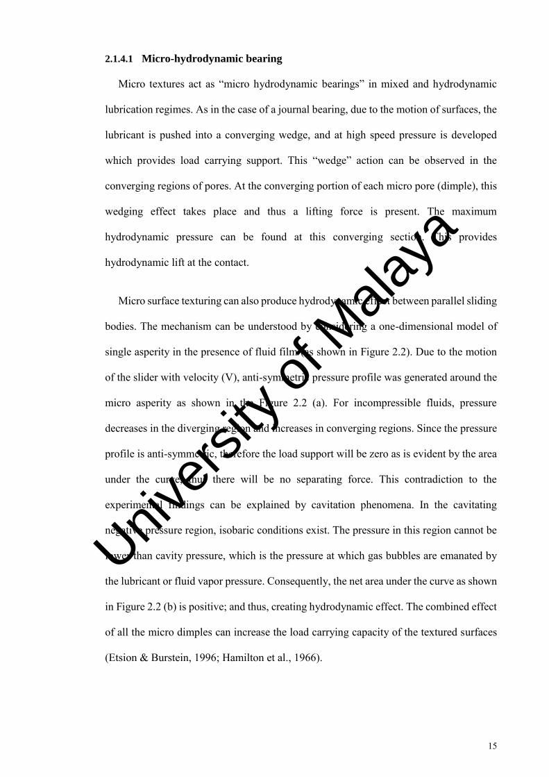
Micro surface texturing can also produce hydrodynamic effect between parallel sliding
bodies. The mechanism can be understood by considering a one-dimensional model of
single asperity in the presence of fluid film (as shown in Figure 2.2). Due to the motion
of the slider with velocity (V), anti-symmetric pressure profile was generated around the
micro asperity as shown in the Figure 2.2 (a). For incompressible fluids, pressure
decreases in the diverging region and increases in converging regions. Since the pressure
profile is anti-symmetric, therefore the load support will be zero as is evident by the area
under the curve, thus there will be no separating force. This contradiction to the
experimental findings can be explained by cavitation phenomena. In the cavitating
negative pressure region, isobaric conditions exist. The pressure in this region cannot be
lower than cavity pressure, which is the pressure at which gas bubbles are emanated by
the lubricant or fluid vapor pressure. Consequently, the net area under the curve as shown
in Figure 2.2 (b) is positive; and thus, creating hydrodynamic effect. The combined effect
of all the micro dimples can increase the load carrying capacity of the textured surfaces
(Etsion & Burstein, 1996; Hamilton et al., 1966).
Univers
ity of
Mala
ya

16
Figure 2.2: Hydrodynamic pressure profiles by a micro asperity (a) without
cavitation (b) with cavitation
2.1.4.2 Lubricant reservoir
Surface textures can act as lubricant reservoirs or secondary lubricant source (Amanov
et al., 2013; Kovalchenko et al., 2011; Vandoni et al., 2012; Wang & Kato, 2003). During
sliding the lubricant will be drawn up to permeate the surfaces (as shown in Figure 2.3).
This phenomenon can reduce friction, wear and seizer.
Univers
ity of
Mala
ya

17
Figure 2.3: Secondary lubrication mechanism (Wang & Kato, 2003)
2.1.4.3 Wear debris storage ability
The most common wear mechanisms in the generation of wear debris are mentioned
below.
I. Abrasive wear: In abrasive wear, material is removed due to hard abrasive
phases. Both 2nd body and 3rd body abrasion is generated according to the
morphology of abrasive phases. In the case of complex morphologies, 2nd
body abrasion is realized, while 3rd body abrasion is possible for simple
morphologies (Rabinowicz, 1995).
II. Adhesive wear: adhesive wear takes place when a surface slides against
another surface, causing shards of one surface to stick to the other surface
and eventually pull out from the original surface. Strong adhesive forces,
which come into existence when atoms come into close contact with one
another, mainly cause adhesive wear (Rabinowicz, 1995). At interfacial
Univers
ity of
Mala
ya
18
pressure or high temperature, a strong bond can be formed between debris
and sliding surfaces.
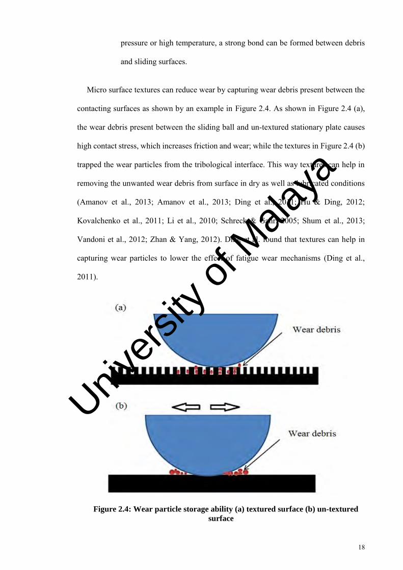
Micro surface textures can reduce wear by capturing wear debris present between the
contacting surfaces as shown by an example in Figure 2.4. As shown in Figure 2.4 (a),
the wear debris present between the sliding ball and un-textured stationary plate causes
high contact stress, which increases friction and wear; while the textures in Figure 2.4 (b)
trapped the wear particles from the tribological interface. This way textures can help in
removing the unwanted wear debris from surface in dry as well as lubricated conditions
(Amanov et al., 2013; Amanov et al., 2013; Ding et al., 2011; Hu & Ding, 2012;
Kovalchenko et al., 2011; Li et al., 2010; Schreck & Gahr, 2005; Shum et al., 2013;
Vandoni et al., 2012; Zhan & Yang, 2012). Ding et al. found that textures can help in
capturing wear particles to lower the effect of fatigue wear mechanisms (Ding et al.,
2011).
Figure 2.4: Wear particle storage ability (a) textured surface (b) un-textured
surface
Univers
ity of
Mala
ya

19
2.1.5 Fabrication techniques of surface textures
Surface textures can be fabricated by using different techniques, which includes
photolithography and etching (Lu & Khonsari, 2007; Yan et al., 2010), shot blasting
(Nakano et al., 2007), CNC micro machining and laser surface texturing (Etsion, 2005;
Wakuda et al., 2003), electric discharge machining (Uhlmann & Doll, 2005), CNC
ultrasonic machining (Churi, 2010), focused ion beam machining (Tseng, 2004), vibro-
mechanical texturing (Greco et al., 2009), micro grinding (Masuzawa, 2000; Nguyen &
Butler, 2005), micro casting (Cannon & King, 2009) and CNC drilling (Roy et al., 2014).
Among these, laser surface texturing has been found to have several advantages like high
spatial resolution, non-contact, processing flexibility (Gao et al., 2011; Kuršelis et al.,
2012) and creation of well-defined patterns with accuracy (Kuršelis et al., 2012).
2.1.6 Laser surface texturing
LST uses high energy pulses to ablate material by rapid melting and vaporizing. Laser
ablation can be defined as the removal of material by direct absorption of laser energy.
The start of ablation occurs above the threshold fluence. This threshold depends on the
micro-structure, morphology, absorption mechanism, material properties and defects, and
laser properties, such as wavelength and pulse duration (Dong et al., 2011). Laser ablation
can be divided into the following two categories depending upon the interaction of laser
energy of the material: pyrolytic and photolytic processes (Meijer, 2004). In the pyrolytic
process, laser energy is absorbed by the material and then transferred into heat, which
causes an increase in temperature. As a result, the material melts and evaporates from the
surface. In the photolytic process, the photon energy absorbed induces chemical reactions
to overcome the chemical binding energy of molecules; this is also called “cold ablation”
(Meijer, 2004).
Univers
ity of
Mala
ya

20
The way in which the laser beam is projected to the substrate determines the texture
accuracy. The methods used in this regard are as follows:
1. A fast-revolving perforated disk is used to practically chop an unfocused
laser beam in order to create patterns; however, this technique is generally
avoided due to its limited resolution, flexibility, and accuracy (Coblas et al.,
2009).
2. A patterned mask is used to split the laser beam projected onto the sample.
This technique is flexible, fast, accurate, and allows the creation of various
shaped micro-features. The production cost of the mask is the main
drawback to this technique.
3. A laser beam can be projected by the use of a galvanometric scanner and a
computer numerical control (CNC) system, which maneuvers the beam over
the sample (Vincent et al., 2008). This technique is extremely accurate due
to the very short pulses (duration of pulse fs and ns). The main drawback is
that this is a time-consuming process, as each texture is machined separately
(Coblas et al., 2014).
Some of the important issues regarding LST are: the heat affected zone (HAZ),
surface defects (burrs or bulges), and the formation of periodical surface structures. Laser
beam heat can affect the substrate and cause variations in its metallurgical properties. For
example, for a pore area ratio of 14–22.5%, the area ratio of the HAZ reaches 50–100%,
while HAZ diameter varies from 300–450 µm around the dimples for SiC rings (Wang
et al., 2001). Similarly, dimensions of the thermally affected area surrounding the hole
with a diameter of 10 µm produced using Nd:YAG pulses are less than 10% of the texture
diameter (Kononenko et al., 2000). Surface defects (burrs or bulges) are another main
problem. Frictional behavior is affected by bulges, as they have significant height, i.e.
Univers
ity of
Mala
ya

21
3.5–4.5 µm (Amanov et al., 2012). This volume of material is commonly removed from
the textured surface by grinding, surface polishing, and lapping. Another issue that has
been observed in ns and fs laser-textured substrate is the formation of periodical surface
structures, such as, ripples that cause an increase in the roughness on the surface. This is
recognized as surface acoustic waves or an interference phenomenon (Coblas et al.,
2014). Researchers have used this issue of LST to their advantage to create periodical
structures for controlling hydrophobicity of metals (Römer et al., 2009) and friction and
wear properties of cutting tools (Sugihara & Enomoto, 2009).
The advantages of laser surface texturing systems are high precision, dimensional
accuracy, and no contact force required. The disadvantages include low machining speed,
high cost of equipment, and difficult maintenance and adjustment.
2.1.7 Applications of micro surface texturing
Different types of surface texturing have been used to obtain the tribological
performance enhancement. These include connected textures like different patterns of
grooves and disconnected independent textures like micro dimples. In the case of
connected textures, the parameters that affect the tribological performance of contacting
surfaces are pitch of textures, width of texture, depth of texture etc. In the case of
disconnected independent textures like micro dimples. The relevant parameters are
dimple depth, dimple diameter, dimple depth to diameter ratio and dimple density, etc.
Several researchers have contributed to the effects of the above-mentioned parameters
for the tribological performance piston ring/cylinder assembly (Abboud et al., 2007;
Bolander & Sadeghi, 2006; Caciu et al., 2008; Checo et al., 2014; Etsion et al., 2006;
Etsion & Sher, 2009; Gadeschi et al., 2012; Kligerman et al., 2005; Ryk & Etsion, 2006;
Ryk et al., 2005; Tomanik, 2013; Wos & Michalski, 2011; Zhan & Yang, 2012),
mechanical seals (Chen et al., 2012; Feldman et al., 2006; Feldman et al., 2006;
Univers
ity of
Mala
ya

22
Kligerman & Shinkarenko, 2011; Qiu and Khonsari 2011a, 2011b; Wan & Xiong, 2008;
Wang et al., 2014; Wang et al., 2006), bearings (Brizmer et al., 2003; Lu & Khonsari,
2007; Marian et al., 2011; Qiu et al., 2014; Qiu et al., 2012; Qiu et al. 2013; Rahmani, et
al., 2010), cutting tools (Deng et al., 2013; Enomoto & Sugihara, 2010, 2011; Enomoto
et al., 2012; Jianxin et al., 2012; Kawasegi et al., 2009; Koshy & Tovey, 2011; Lei et al.,
2009; Ling et al., 2013; Neves et al., 2006; Obikawa et al., 2011; Sugihara & Enomoto,
2009, 2012, 2013; Wu et al., 2012; Xie et al., 2012; Xing et al., 2014; Ze et al., 2012;
Zhao et al., 2010) and hydraulic motors (Pettersson & Jacobson, 2007).
2.1.7.1 Piston ring/cylinder assembly
As the piston ring/cylinder assembly accounts for 25 % of total mechanical loss in
engine, several researchers are working on reducing this power loss. Different types of
surface treatments for piston/cylinder assembly used to reduce the friction and wear.
Reduction of frictional losses by changing the surface roughness in the form of surface
textures has been reported in case of piston rings by several researchers (Abboud et al.,
2007; Bolander & Sadeghi, 2006; Caciu et al., 2008; Checo et al., 2014; Etsion et al.,
2006; Etsion & Sher, 2009; Gadeschi et al., 2012; Kligerman et al., 2005; Ronen et al.,
2001; Ryk & Etsion, 2006; Ryk et al., 2002; Ryk et al., 2005; Tomanik, 2013; Usman &
Park, 2016; Wos & Michalski, 2011; Zhan & Yang, 2012). Mainly the textures created
in case of piston rings are in the form of the array of uniform depressions or pored with
similar geometrical dimensions to one another, these are usually called dimples as shown
in Figure 2.5.
Lasers have been mainly used by researchers to create these dimples on piston rings.
By creating dimples on the piston ring surface, researchers have found the reduction in
friction at the piston ring/cylinder contact in the range of 20-50 % in comparison to un-
textured piston rings (Kligerman et al., 2005; Ryk & Etsion, 2006; Ryk et al., 2005).
Univers
ity of
Mala
ya

23
Figure 2.5: Surface textured piston ring
2.1.7.2 Cutting tools
Surface texturing to improve the cutting performance of tools is a recent endeavor.
Figure 2.6 shows laser surface textured tool with rectangular textures. These textures
improve the cutting performance by enhancing lubricant availability at the contact point,
reducing the tool-chip contact area, and trapping wear debris (Chang et al., 2011; Silva,
et al., 2013; Deng et al., 2013; Enomoto & Sugihara, 2010, 2011; Enomoto et al., 2012;
Jianxin et al., 2012; Kawasegi et al., 2009; Koshy & Tovey, 2011; Lei et al., 2009; Ling
et al., 2013; Obikawa et al., 2011; Sugihara & Enomoto, 2009, 2013; Wu et al., 2012; Xie
et al., 2012; Xing et al., 2012; Ze et al., 2012). The benefits of surface textures have been
observed in both wet and dry cutting of aluminum alloys, titanium alloys, and mild and
hardened steel. To date, this technique has been successfully used in drilling, milling, and
turning operations.
Univers
ity of
Mala
ya

24
Figure 2.6: Micro-textured drill bit (Ling et al., 2013)
2.1.7.3 Mechanical seals
Surface texturing has been recognized to improve the tribological performance of
mechanical seals. Through the surface texturing on mechanical seals researchers have
found the reduction in friction and wear, enhanced ant seizer ability, reduction in leakage,
increase in fluid film thickness and increased load carrying ability (Chen et al., 2012;
Feldman et al., 2006; Feldman et al., 2006; Kligerman & Etsion, 2001; Kligerman &
Shinkarenko, 2011; Qiu & Khonsari, 2011a, 2011b; So & Chen, 2005; Wan & Xiong,
2008; Wang et al., 2014; Wang et al., 2006; Wang & Hsu, 2004).
2.1.8 Effect of surface texture parameters on friction and wear characteristics
2.1.8.1 Dimple depth and diameter
Surface texture performance is dependent on its parameters. If the contact has low
lubricant availability, then the deep dimples detrimental effects were observed in terms
of friction and wear (Bolander & Sadeghi, 2006; Ryk et al., 2002). When there is low
lubricant availability at the contact, deep dimples become micro traps of lubricant. The
Univers
ity of
Mala
ya

25
lubricant starts to get concentrated around the dimples compared to un-textured contact
where it is reasonable to assume that it is evenly distributed over the contact. Due to this,
the hydrodynamic effect of the “micro-hydrodynamic bearing” reduces to only small area
and the clearance between the surfaces reduces, thus increasing friction and wear in
comparison to un-textured surfaces. This phenomenon can occur earlier if the viscosity
of the lubricant is high due to low fluidity of lubricant (Ryk et al., 2002).
Wang et al. (Wang & Kato, 2003) evaluated the anti-seizer ability of a textured silicon
carbide (SiC) specimens in water lubrication using critical load as the performance index.
The authors found that due to an increase in dimple depth in the range (2-13.3 um), the
critical load increases too (Wang & Kato, 2003). This result was in contradiction with the
group’s previous work (Wang et al., 2003). X. Wang et al. found that an increase in
dimple depth is not beneficial for load carrying capacity. They suggested an optimum
range of 2-7 µm depth (90 um diameter) in case of steel rings sliding in oil and 0.015
depth to the diameter ratio in case of SiC bearing working in water (Wang et al., 2003).
Wang et al. recommended that this dissimilarity might be due to the reason that
tribochemical reaction of SiC in water is the more important factor than hydrodynamic
lubrication (Wang & Kato, 2003). Deep dimples can store more water for tribochemical
reaction as a result they increase the anti-seizer ability. In case of oil lubrication, deep
dimples do not enhance the hydrodynamic effect.
Tomanik et al. also investigated various dimple depth and diameter using an one-
dimensional computer program (Tomanik, 2013). Dimple's depth has been varied from 1
to 10 µm and diameter from 10 to 100 µm. They found that higher hydrodynamic pressure
can be obtained by using dimple depth of 1 µm and diameter of 10 µm in comparison to
5 µm depths and 25 µm diameters.
Univers
ity of
Mala
ya

26
In the case of non-conformal contacts and under elastrohydrodynamic lubrication
regime (EHL), the dimple depth is found to have effect on the local change in the lubricant
film thickness (Mourier et al., 2010). Mourier et al. investigated depth effect using EHL
iris Tribometer (Mourier et al., 2010). They found that if the depth of the dimple is high,
the lubricant passing through the dimple has the lower pressure level, and thus, the
viscosity of the lubricant will drop and this prevents the lubricant to separate the surfaces.
They observed that 300 nm dimple depth increased the film thickness.
In mechanical components, i.e., gears, cams, reduction in friction due to surface
texturing in line contacts has been a topic of great interest for many researchers. Hao et
al. investigated the friction and wear performance under non-conformal line contacts.
They observed reduction in wear marks or debris on line contact slider bearing (contact
between flat disc and cylinder) which is used in cam mechanism (Hao et al., 2014).
Deciding the right dimple diameter for non-conformal contact is a bit difficult
compared to conformal contacts. It was stated that surface texturing is not helpful in
friction reduction when the diameter of dimple is equal to or smaller than Hertz contact
width, while the coefficient of friction reduces significantly when dimple diameter is
greater than Hertz contact width (Wakuda et al., 2003). Xiaolei et al observed different
results in pin on disk tests, they observed that if the dimple diameter is equivalent or
smaller than the contact width, the friction reduction can be observed (Xiaolei et al.,
2009). Further investigation is needed in order to clarify these contradictions.
Recently, Wang et al. investigated two-phase mechanical seals with laser surface
textured end faces using transparent rotating rings so that the distribution of liquid/vapour
region can be observed using a camera (Wang et al., 2014). The results showed that the
surface textured rings with small dimples (diameter 1000 µm and depth of 10 µm) have
lower mean temperature at various speeds than flat ring and textured rings with larger
Univers
ity of
Mala
ya
27
dimples (diameter 2000 µm and depth of 40 µm). The authors also found that if the dimple
depth and diameter are both high, the vaporization is higher than plain end face because
larger the diameter of dimples larger will be the cavitation, which will abruptly increase
friction torque (Wang et al., 2014).
2.1.8.2 Dimple density
Dimple density can be defined as number of dimples per unit area. Kligerman et al.
through several numerical simulations found that the area density of the dimples should
be largest in order to get higher friction reduction in the case of conformal contacts. The
range of dimple density chosen by researchers varies between 5-66 % (Kligerman et al.,
2005).
As surface texturing increases, fluid film thickness and creates additional
hydrodynamic pressure between interacting surfaces, subsequently it causes significant
reduction in friction. A lot of research has been conducted with an objective to minimize
the friction by surface texturing, which is equally effective in terms of wear and increases
the operational life of materials. Siripuram & Stephens observed that cross-sectional area
of dimples can affect friction (Siripuram & Stephens, 2004). Tonder analytically studied
effects of micro dimples on pivoted bearings, and observed a significant reduction in
friction under particular conditions due to increased film thickness and load capacity
(Tønder, 2010). Findings of Tonder about the effects of dimple density on friction were
verified experimentally and analytically in several studies (Tanu et al., 2010; Yan et al.,
2010). For example, Wang et al. worked on thrust bearings with circularly textured micro
dimples under water based lubrication condition, and found that friction of a coefficient
reduces tremendously, and this effect becomes more significant with an increase in
density and size (Wang et al., 2003).
Univers
ity of
Mala
ya

28
In the case of non-conformal contact, Wakuda et al. used steel cylinders, which were
sliding on the ceramic plate (Wakuda et al., 2003). They varied the texture density from
7.5 to 30 %. The lowest coefficient of friction at various sliding speeds was shown by 7.5
% density (Figure 2.7). As the density was increased to 30 % coefficient of friction also
increases. Qui et al. used universal tribometer to simulate conformal contact (Qiu &
Khonsari, 2011a). They varied dimple density from 15 to 58.6 %. Figure 2.8 shows that
a highest dimple density of 58 % showed the lower coefficient of friction compared to
less density at 4.5 N and 18 N load. The highest coefficient of friction was shown by un-
textured samples. For conformal contacts, mostly authors found higher dimple density to
be beneficial in reduction of coefficient of friction, whereas for non-conformal lower
density has been found useful.
Figure 2.7: Effect of change in dimple density on coefficient of friction (Wakuda
et al., 2003)
Univers
ity of
Mala
ya

29
For textured 316 stainless steel, relationship between texture density and coefficient
of friction were also analyzed by (Zhang et al., 2013). They reported that coefficient of
friction reduces for 10 % dimple density compared to higher or lower dimple density
(Figure 2.9). Wear depth was also reduced for surface textured steel than un-textured
steel. It was also indicated that reduction in friction caused reduction in wear depth.
Figure 2.8: Effect of change in dimple density on coefficient of friction at
various loads (Qiu& Khonsari, 2011a)
0
0.5
1
1.5
2
2.5
3
Load 4.5 NLoad 18 N
Coef
fici
ent
of
Fri
ctio
n
Dimple Density 40 %
Dimple Density 58 %
Plain Sample
Univers
ity of
Mala
ya

30
Figure 2.9: Variation in coefficient of friction with change in area density
(Zhang et al., 2013)
2.2 Laser surface textured diamond like carbon coatings
2.2.1 Diamond like carbon coating
For several years, beneficial tribological properties of carbon have been
acknowledged. Its performance depends upon form of carbon and its interaction with a
particular operating setup. Due to remarkable lubrication properties of graphite, it has
found countless applications in different fields including electrical contacts, abradable
seals and metallurgical applications. In these applications, performance benefits are
achieved due to sliding of basal planes over each other, which are further enhanced by
adsorptive properties of water or oxygen (Hutchings, 1992). On the other hand, diamond
is considered an ideal material for wear resistance due to its very high chemical inertness
and hardness, which makes it beneficial in variety of applications including grinding and
polishing tools, scalpels and wire drawing dies (Davis, 1991).
2.2.1.1 Types and structure of DLC coatings
Structures of sp2 and sp3 carbon atoms may be different in diamond like-carbon
materials, while the amount of hydrogen contained by these materials can be negligibly
Univers
ity of
Mala
ya

31
small or absent at all. In 1986, Robertson explained the structure of DLC as a random
network in which carbon atoms are covalently bonded and have different hybridizations
(Robertson, 1986). Robertson refined his model in 1997 and showed that energy of π
bonds of sp2 sites controls the structure of both ta-C and a-C:H coatings (Grill, 1999).
Figure 2.10 presents the phase diagram of hydrogen, sp2 and sp3 contents in the different
form of diamond like-carbon. Lower left-hand corner shows the graphitic carbon. The
lower right-hand corner shows higher hydrogen content phases (gas or liquid molecules).
Amorphous hydrogenated carbon (a-C:H) coating is present in the middle of the diagram,
representing varying amounts of sp2, sp3 bonds and hydrogen contents. The tetrahedral
amorphous carbon (ta-C) is present at the left side indicating varying amount of sp2, sp3
bonds.
On the basis of chemical structure, DLC coatings can be distinguished as pure (non-
doped DLC coatings) and modified (doped DLC coatings). Pure or non-doped coating
contained C or/and H only, whereas modified i.e., doped coatings also have some metallic
(W, Mo, Ti etc.) and non-metallic (Si, F, C etc.) components. Based on practical
applications of DLC coating, metal and nonmetal dopant are selected. Based on hydrogen
content, DLC coatings are further classified in two major categories, namely, non-
hydrogenated DLC coatings and hydrogenated DLC coatings. Non-hydrogenated DLC
coatings have negligibly small hydrogen content, and they include tetrahedral (ta-C) and
amorphous (a-C) DLC coatings. While hydrogenated DLC coatings contain the
significant amount of hydrogen; amorphous (a-C:H) and tetrahedral (ta-C:H) DLC
coatings are classified as hydrogenated DLC coatings (Velkavrh et al., 2008).
Univers
ity of
Mala
ya

32
Figure 2.10: Ternary phase diagram showing sp3, sp2, and hydrogen contents
of different DLC coatings (Robertson, 2002)
2.2.1.2 Deposition technique
Deposition technique is one of the main factors, which has significant influence on the
properties of diamond-like carbon coating. Different deposition techniques have been
introduced for depositing DLC films. For DLC coating there exist a wide range of
deposition temperature, varying from sub-zero to 400 ºC. Depending upon the deposition
technique; bias voltage, etching time and deposition gas pressure may also have a wide
range of varying values. Higher flexibility of DLC coating has attracted attention from
many researchers. Some common deposition techniques are magnetron sputtering, ion
beam deposition, hot filament chemical vapor deposition (HFCVD), plasma-activated
chemical vapor deposition (PACVD) and plasma immersion ion implantation and
deposition (PIII-D) (Al Mahmud et al., 2015).
Univers
ity of
Mala
ya
33
Magnetron sputtering is most commonly adopted deposition technique these days.
This technique is applicable for DLC coating under both hydrogenated and non-
hydrogenated conditions. Puchi-Cabrera et al. employed this technique for depositing
hydrogenated DLC coating (Puchi-Cabrera et al., 2010). To improve DLC coating
adhesion, they deposited an interlayer of Cr, and butane gas worked as source of hydrogen
and carbon source. By following the same process Peng et al. coated non-hydrogenated
DLC, but graphite source has been used in their work for deposition (Peng et al., 2001).
By using a pure graphite target in Argon plasma, non-hydrogenated film with thickness
up to 1 µm were made by sputtering. Working principle of magnetron sputtering is
described as follows: high-energy ions created from discharge plasma are bombarded on
a target plate (cathode), the bombardment process removes targeted atoms and thin film
of these atoms is condensed on the substrate. Ion bombardment also caused emission of
secondary electrons from the target surface. Plasma is maintained by emitted secondary
electrons. Magnets are placed parallel to target in such a way that secondary electrons are
trapped that increase the chance of electron collision and thus supports in sustaining
plasma (Johnson & Cote, 2006; Kelly & Arnell, 2000; Tung & McMillan, 2004).
2.2.1.3 Influence of hydrogen content on DLC coating
The influence of hydrogen content on the tribological characteristics of DLC coatings
can explain the sensitivity of a coefficient of friction to various environments such as
humid and dry air. In the case of non-hydrogenated coatings, there exists strong adhesive
forces between tribological surfaces. Therefore, value of COF in the vacuum is usually
greater than 0.5. On the other hand, for hydrogenated coatings, COF is very less (COF<
0.001) (Erdemir, 2001).
For normal air exposed environment, a different behavior has been observed,
coefficient of friction of non-hydrogenated decreases significantly while it increases for
Univers
ity of
Mala
ya

34
hydrogenated DLC coating (Erdemir, 2001). The reason for this difference in behavior
with change in environment can be explained by passivation of DLC coating surface with
hydrogen. In the presence of hydrogen in DLC coatings, or when DLC coatings have
hydrogenated environment, carbon and hydrogen atom's bond with each other, as a result,
number of sites were contacting surfaces can form covalent bond is reduced, and thus
adhesion gets lower. For non-hydrogenated DLC coatings, this mechanism does not occur
due to the absence of hydrogen in the microstructure of the coating, and therefore, in inert
environment or vacuum reactivity of non-hydrogenated DLC coated surfaces caused high
adhesion (Sutton et al., 2013).
DLC interacting surfaces contain some unbound σ bonds. In order to minimize the
coefficient of friction it is important to eliminate this type of bonds. In case of
hydrogenated DLC, hydrogen can continuously passivate such bonds. Hydrogen exists
within the matrix in the molecular and atomic state; and it works like a reservoir.
Unwanted bonds are constantly passivated by these molecules, resulting in the decrease
of surface energy. This process effectively minimizes friction (Semenov & Khrushchov,
2010).
2.2.1.4 Effect of sp3/sp2 ratio
Characteristics of DLC films i.e. hardness, elastic modulus, internal stresses, are
directly related to the fraction of sp3 carbon contained by films. DLC films generally have
high elastic modulus, high hardness and high internal stresses. Higher the sp3 content
higher will be the hardness. Highest amount of sp3 contents (80-88%) is found in
tetrahedral carbon coating.
Al Mahmud et al. compared the tribological performance of tetrahedral amorphous
and amorphous hydrogenated carbon coatings in oil lubricated conditions (Al Mahmud
et al., 2014). The oil lubricated testing results indicated that due to higher sp3 content in
Univers
ity of
Mala
ya

35
tetrahedral amorphous coating the wear rate was lower than amorphous hydrogenated
carbon coating. The Raman spectroscopy results showed lower transformation of sp3 to
sp2 content which indicates that tetrahedral amorphous showed lower graphitization than
amorphous hydrogenated carbon coating (Al Mahmud et al., 2014). Ronkainen et al.
compared the tribological properties of amorphous hydrogenated carbon and tetrahedral
amorphous carbon coatings in dry environment (Ronkainen et al., 2001). The amount of
sp3 bonds in tetrahedral amorphous and amorphous hydrogenated carbon coatings is high,
however amorphous hydrogenated carbon shows more pronounced transformation to
graphite structures. Some hydrogen-depleted sections are formed due to heat induced by
friction. This friction induced heating can easily break down C-H bonds, so such regions
become highly favorable for graphitization. As tetrahedral amorphous carbon coating has
more stable sp3 bonding than amorphous hydrogenated carbon coating, therefore for
tetrahedral amorphous carbon coating graphitization rate is much lower, additionally, less
pronounced transfer layer is formed for tetrahedral amorphous carbon coating compared
to amorphous hydrogenated carbon coating.
2.2.1.5 Effect of temperature on friction of DLC coatings
Diamond-like carbon is a form of diamond, which is thermodynamically metastable.
Graphitization or decomposition of amorphous hydrogenated carbon coating occurs once
the temperature is increased. This process occurs through the release of hydrogen from
the film structure. At a certain temperature normally refers to as threshold temperature,
dehydrogenation of amorphous hydrogenated carbon coating to graphite crystallites
occurs (Liu & Meletis, 1997). The hardness of amorphous hydrogenated carbon coating
remains nearly constant up to 700 ºC, this can be due to the partial crystallization of
graphite grains. The thermal stability of tetrahedral amorphous carbon coating is up to
1000 ºC temperature. This is because of lower hydrogen content in its structure (Kalish
et al., 1999; Ronkainen, 2001).
Univers
ity of
Mala
ya

36
Graham et al. investigated the effects of temperature on wear properties and coefficient
of friction of tungsten doped DLC coating (Gharam et al., 2011). They observed that
above 250 ᵒC, the sp3 to sp2 bond's transformation takes place. As graphite has layered
structures, it serves as a solid lubricant. Between each layer of structure, Van's der Waals
bonds existed, but these bonds are not strong enough and allow the layers to slide over
each other, which results in the decrease of a coefficient of friction. In lower temperature
zone, coefficient of friction gradually increases by the increase in temperature as a result
of evaporation of water molecules attached to the coated surface.
Wang et al. applied thermogravimetric analysis (TGA) to study the oxidation
properties of DLC coating (Wang et al., 1999). They observed intense oxidation at a
temperature range of 350-400 ºC. Frictional properties are also affected at this
temperature range. Frictional properties are affected differently for hydrogenated and
non-hydrogenated DLC coatings. Gao et al. demonstrated that hydrogen desorption
occurs from the coating surface of amorphous hydrogenated carbon coating when it is
heated at 147ᵒ C, which causes the increase in the coefficient of friction (Gao et al., 2005).
2.2.1.6 Effect of temperature on wear of DLC coatings
The thermal instability of DLC coating causes its wear behavior to be dependent on
temperature. Some DLC coatings wear characteristics in ambient air has been observed
to reduce with temperature increase from 100-300 °C (Grill, 1999). In another
investigation, with the increase in temperature to 150 °C, it has been observed in the case
of self-mated amorphous hydrogenated carbon coating that friction reduced and wear rate
increased because of graphitization (Grill, 1999).
Highly disordered structure of DLC film steadily transforms to ordered structure at the
elevated temperatures. Films form an unsteady phase during deposition, when thermal
energy is introduced, structure of these films is re-oriented (Erdemir & Fenske, 1996; Wu
Univers
ity of
Mala
ya

37
& Hon, 1999). At high temperature, diffusion of unbounded hydrogen atoms produced a
spongy structure in the film of hydrogenated DLC. These structural and chemical changes
also cause modifications in friction and wear behavior. After exposing at high
temperature, final product may become highly porous and a soft graphitic thin layer may
appear, which wears out rapidly. At elevated temperature, endurance limit for non-
hydrogenated films is higher than hydrogenated films.
Veverkova et al. proved that at the different number of rotations (10 and 100 cycles)
and loads (7 and 10 N), wear coefficients also increase with the increase in temperature
in the case of tungsten doped DLC coating (Veverkova & Hainsworth, 2008). They
observed that at 7 N and 10 N loads wear coefficient is higher for 10 cycles. Although,
as time increases wear rate gets lower since abrasive wear occurs initially. Krumpiegl et
al. investigated wear behavior and friction of amorphous carbon. Titanium doped DLC
and amorphous hydrogenated carbon at 450ᵒ C for both air-exposed and vacuum chamber
environments. They observed that hardness is not lost after testing under vacuum chamber
environment (Krumpiegl et al., 1999). However, for air exposed environment major loss
of hardness is observed due to oxidation.
2.2.2 Combination of laser surface texturing and DLC coatings
Very few studies can be found related to surfacing at textured DLC coating.
Tribological performance enhancement of DLC coatings using micro textures has been
found by (Amanov et al., 2013; Ding et al., 2010; Dumitru et al., 2003; Enomoto &
Sugihara, 2010; Komlenok et al., 2016; Koskinen et al., 2010; Oksanen et al., 2014;
Pettersson & Jacobson, 2003; Pettersson & Jacobson, 2004; Song et al., 2014; Sugihara
& Enomoto, 2009). Researchers have studied using mostly indirect laser texturing
method, as it is difficult to control coating properties with direct laser texturing. Mostly,
Univers
ity of
Mala
ya
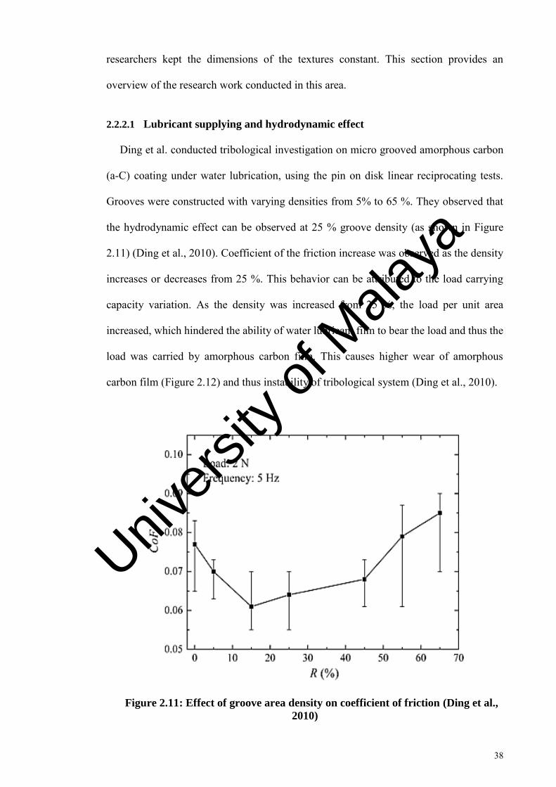
38
researchers kept the dimensions of the textures constant. This section provides an
overview of the research work conducted in this area.
2.2.2.1 Lubricant supplying and hydrodynamic effect
Ding et al. conducted tribological investigation on micro grooved amorphous carbon
(a-C) coating under water lubrication, using the pin on disk linear reciprocating tests.
Grooves were constructed with varying densities from 5% to 65 %. They observed that
the hydrodynamic effect can be observed at 25 % groove density (as shown in Figure
2.11) (Ding et al., 2010). Coefficient of the friction increase was observed as the density
increases or decreases from 25 %. This behavior can be attributed to the load carrying
capacity variation. As the density was increased from 25 %, the load per unit area
increased, which hindered the ability of water lubricant film to bear the load and thus the
load was carried by amorphous carbon film. This causes higher wear of amorphous
carbon film (Figure 2.12) and thus instability of tribological system (Ding et al., 2010).
Figure 2.11: Effect of groove area density on coefficient of friction (Ding et al.,
2010)
Univers
ity of
Mala
ya

39
Figure 2.12: Effect of groove area density on wear rates (Ding et al., 2010)
In order to evaluate lubricating properties of textures under boundary conditions,
Petterson et al. conducted ball on plate reciprocating tribological tests using poly alpha
olefin as a lubricant (Pettersson & Jacobson, 2003). Textures such as grooves and squares
were created with varying widths (5, 20 and 50 µm) using photolithographic technique.
The results indicate that only smallest grooves and squares showed low and stable friction
of 0.05. This behavior was attributed to the well working supply of lubricant from the
textures at the ball/plate contact. In another study conducted by Petterson et al., similar
results were found with the smallest grooves and squares (Pettersson & Jacobson, 2004).
Surface textured and un-textured DLC coatings were compared for cutting application.
Various types of structures were created on the rake face of the tools to explore these
effects on improving cutting tool performance, including DLC-coated sine wave-shaped
Univers
ity of
Mala
ya

40
grooves (Sugihara & Enomoto, 2009); DLC-coated banded grooves in which textures
were sandwiched between polished areas to ensure that lubricant leakage was prevented
(Sugihara & Enomoto, 2009).
Comparison of the DLC coated sine wave grooved tool, and the DLC coated banded
grooved tool in face milling experiments was conducted in dry and wet cutting conditions
in order to analyze the effect of the lubricant storage and supply ability of textures
(Sugihara & Enomoto, 2009). The aluminum atom concentration in EDX-Al imaging was
measured in order to quantitatively analyze aluminum adhesion. In the case of wet
cutting, the concentration of aluminum atoms for banded grooved tools was lowest, as
compared to sine wave (parallel and perpendicular) grooves and un-textured. A reduction
of the friction coefficients has also been found using the banded grooves on the tool rake
face, as compared to the sine wave textured and un-textured tools. The reason for the
superior performance of the DLC coated banded grooves compared to DLC coated sine
wave, and un-textured DLC coated tool is that they retain and provide lubricant at the
interface, keeping the lubricant leakage to a minimum (Enomoto & Sugihara, 2010). The
importance of storing and providing lubricant ability has also been found in the dry
cutting of aluminum. The aluminum atom concentration was found to be higher in the
textured tool than the un-textured tool, which also indicates that lubricant
storing/providing ability is necessary for adhesion reduction (Sugihara & Enomoto,
2009). Additionally, in the case of milling steel, sine-wave grooves did not enhance tool
performance, due to a lack of lubricant storing ability.
2.2.2.2 Wear particle entrapment
Dumitru et al. (2003) evaluated the effect on an increase in load on the tribological
performance of textured and un-textured amorphous hydrogenated carbon coating. The
load was varied from 50 to 200 N. The textures were created using indirect laser texturing.
Univers
ity of
Mala
ya
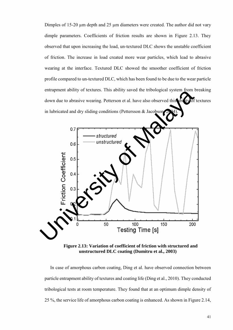
41
Dimples of 15-20 µm depth and 25 µm diameters were created. The author did not vary
dimple parameters. Coefficients of friction results are shown in Figure 2.13. They
observed that upon increasing the load, un-textured DLC shows the unstable coefficient
of friction. The increase in load created more wear particles, which lead to abrasive
wearing at the interface. Textured DLC showed the smoother coefficient of friction
profile compared to un-textured DLC, which has been found to be due to the wear particle
entrapment ability of textures. This ability saved the tribological system from breaking
down due to abrasive wearing. Petterson et al. have also observed this ability of textures
in lubricated and dry sliding conditions (Pettersson & Jacobson, 2004).
Figure 2.13: Variation of coefficient of friction with structured and
unstructured DLC coating (Dumitru et al., 2003)
In case of amorphous carbon coating, Ding et al. have observed connection between
particle entrapment ability of textures and coating life (Ding et al., 2010). They conducted
tribological tests at room temperature. They found that at an optimum dimple density of
25 %, the service life of amorphous carbon coating is enhanced. As shown in Figure 2.14,
Univers
ity of
Mala
ya

42
in the start of the test, both the coatings showed the similar coefficient of friction,
however, as the test progressed towards un-textured amorphous carbon coating showed
the reduced coefficient of friction compared to textured amorphous carbon. At the end of
the test, the tribological system of un-textured amorphous carbon coating broke down,
and textured amorphous carbon survived. The phenomenon which caused a reduction of
a coefficient of friction in case of un-textured amorphous carbon coating after 20
minimums is graphitization transformation. At the end of the test, due to graphitization
the un-textured amorphous carbon coating hardness decreased, and eventually film
delamination occurred and coefficient of friction increased.
Figure 2.14: Variation of coefficient of friction with textured and un-textured
a-C film (Ding et al., 2010)
The atomic structure of a-C coating consists of sp3, sp2 and monovalent hydrogen
bonds (Neville et al., 2007). The release of hydrogen from the DLC matrix triggers the
transformation from a sp3 structure to a graphite-like sp2 structure. Graphitization can
occur because of higher contact temperature and/or high contact stress (Haque et al.,
2009). Haque et al. suggested that due to the micron-sized wear particles produced during
Univers
ity of
Mala
ya
43
the sliding test, the contact pressure reduces the graphitization temperature to as low as
95 ºC (Haque et al., 2009). These particles can be generated from counter ball wear
(Haque et al., 2009). Ding et al. proposed that, due to fatigue wear mechanisms, a-C wear
debris can be created at the contact, which can lower the graphitization temperature (Ding
et al., 2010). This can explain the graphitization transformation at room temperature. The
lower graphitization in the case of textured DLC at higher temperatures may be due to
multiple factors, including the wear debris trapping ability and the lubricant retention
ability of micro dimples. Textures can remove the wear debris from the contacting
surface, which can lessen the increase in contact pressure due to the wear particles
between the tribo-pairs. Amanov et al. based on their tribological investigation suggested
that textures provide an easy escape to micro wear particles (Amanov et al., 2013). These
particles if remain on the wear track will cause higher contact loading, which will
eventually cause coating failure. Additionally, by keeping the lubricant at the interface,
they can lower the rise in temperature due to friction-induced heating. In the case of
textured mechanical seals, Xiao et al. (Xiao & Khonsari, 2012) observed that micro
dimples could lower the interface temperature by keeping lubricant at the interface.
Tribological performance of groove textured amorphous hydrogenated carbon under
the vacuum conditions for space applications, has been investigated recently by Song et
al. The textures created with varying pitch distance from 0.1- 1 mm with 30 µm width
and 35 µm depth. They observed that under vacuum conditions, textured amorphous
hydrogenated carbon with pitch distance 0.5 mm shows prolonged wear life (Figure 2.15).
The reductions in adhesive wear and abrasive wear were mainly found responsible for
this enhancement (Song et al., 2014). Wear particles formed at the steel ball and
amorphous hydrogenated carbon disk contacts were captured by textures, thus preventing
further wear and coating delamination. The un-textured amorphous hydrogenated carbon
coating delaminated at several places after the test. They also observed that by varying
Univers
ity of
Mala
ya

44
texture pitch or changing the density, wear particle capturing ability changes. Higher
density reduced the load carrying ability. Low density affects the wear debris entrapping
ability (Song et al., 2014).
Figure 2.15: Coefficient of friction of various textured amorphous hydrogenated
carbon coating samples (textured 1: 1 mm, textured 2:0.5 mm, textured 3: 0.3
mm, textured 4: 0.1 mm) in vacuum condition (Song et al., 2014)
2.3 Bio-lubricants and their tribological properties
Bio-lubricants have high biodegradability and low environmental and human toxicity.
Bio-lubricants are developed from vegetable oils (soybean, palm, sunflower. Coconut,
etc.), synthetic esters and petroleum oils which satisfied the already recognized toxicity
and biodegradability criteria (Kumar & Sharma, 2011).
Bio-lubricant feedstock’s vary from country to country and is dependent upon the
geographical location. The number of oil bearing crops is higher than 350; however,
worldwide attention has been given to only few; such as palm, cottonseed, peanut oil,
Univers
ity of
Mala
ya

45
Jatropha oil, etc. (Singh & Singh, 2010). Palm oil is the main source of bio-lubricant and
bio-diesel in Malaysia.
Vegetable oils have advantages and disadvantages. Advantages include: excellent
lubricity and are biodegradable compared to mineral oil based lubricant; they have the
higher viscosity index (VI), normally they have VI of 223 compared to mineral oil with
VI of 90-100; they also have higher flash temperature compared to mineral oils. The
disadvantages are: low oxidation stability in the natural form; unpleasant odor; limitations
of low-temperature; filter clogging tendency (Mobarak et al., 2014).
In order to increase the oxidation stability and low temperature property's various
techniques has been used such as esterification, transesterification of TMP and ester from
vegetable feedstock, selective hydrogenation, epoxidation and addition of additives
(Zulkifli et al., 2014).
2.3.1 Trimethylolpropane ester
Trimethylolpropane (TMP) ester is a synthetic lubricant. It can be produced from
biodegradable or mineral resources. Biodegradable oils such as palm, jatropha and
sunflower had been used to produce TMP ester (Arbain & Salimon, 2010; Zulkifli, 2014).
TMP ester is produced by transesterification of methyl ester (Aziz et al., 2016). TMP
ester as a bio-lubricant has been used in metal working fluid and engine oils (Zulkifli et
al., 2013) etc. The main reason for using TMP ester as the bio-lubricant is that it has good
thermal and oxidation stability, high viscosity index, friction and wear reducing ability.
2.3.1.1 Tribological performance of trimethylolpropane ester
Generally, researchers found that vegetable-based TMP ester has good tribological
properties. Zulkifli et al. compared the anti-wear properties of palm based TMP ester with
fully formulated lubricant and paraffin oil (Zulkifli et al., 2016). The authors used four
Univers
ity of
Mala
ya

46
balls tribological testing equipment. At 392 N load, they observed that wear scar diameter
for palm based TMP ester is lower than paraffin oil whereas it is higher than fully
formulated lubricant. This was expected as fully formulated lubricant contains anti-wear
additives. Based on the results the authors concluded that palm based TMP ester has
comparable load carrying ability and tribological properties compared to fully formulated
lubricant. Shah et al. found that TMP ester has better friction reducing properties and
acceptable anti-wear properties (Shah et al., 2010).
The lower coefficient of friction shown by palm based TMP ester is because of its high
polarity; because of this reason, it is easily attracted to metal surfaces. Additionally, due
to longer chain lengths, they have higher lubricity. Palm oil has a carbon chain length of
18-20. That is why the formed film behaves as a crystalline solid and reduces friction
(Bhushan, 2013).
In another investigation, Zulkifli et al. observed the effect of temperature on the
tribological performance of palm based TMP ester (Zulkifli et al., 2014). They used four-
ball tester for this tribological investigation. The authors found that palm TMP ester
showed lower coefficient of friction compared to paraffin oil till 80 ºC temperature.
However, as the temperature was increased from 80 to 100 ºC paraffin oil showed lower
coefficient of friction compared to palm based TMP ester. The reason for this behavior
at the higher temperatures is that the lubricant films formed by the fatty acid are less
stable, and they break down easily.
Univers
ity of
Mala
ya

47
CHAPTER 3: RESEARCH METHODOLOGY
3.1 Tribological investigation of laser texture density, diameter and depth
In order to understand the effect of dimple density, diameter and depth on the
tribological performance of amorphous hydrogenated carbon coating, textured and un-
textured amorphous hydrogenated carbon coated samples were created.
3.1.1 Sample preparation
3.1.1.1 Polishing
AISI 52100 steel with a hardness of approximately 60 HRC was used. Steel samples
were cut into dimensions of 15×15 mm in order to use in tribological testing. Steel
samples were initially polished using silicon carbide papers with a grit size range of 400
to 2500 to reduce surface roughness. Afterward, the samples were polished using
diamond suspension with a particle size varying from 6 µm to 1 µm. After polishing, the
average surface roughness was around 30-40 nm.
3.1.1.2 Laser surface texturing
LST uses high-energy pulses to ablate material by rapid melting and vaporizing. Laser
ablation can be defined as the removal of material by direct absorption of laser energy. In
present research work micro surface textures were fabricated using laser surface texturing
(LST). They were fabricated in Singapore institute of manufacturing technology
(SIMtech), Singapore. The specifications of laser used to create micro surface textures
are given in Table 3.1.
Univers
ity of
Mala
ya

48
Table 3.1: Pico second laser specifications
No Laser Specification Value
1 Power 10 W
2 Wavelength 1640 nm
3 Pulse frequency range 50 kHz to 8200 kHz
4 Pulse duration 10.3 pico second
5 Beam Position Speed 1000 mm/s
The samples were fabricated with various texture density, diameter and depth. After
laser surface texturing, bulges were formed around the dimples. These were around 1.5-
2 µm in height. Frictional behavior is affected by bulges (Amanov et al., 2012). This
volume of material was removed from the textured surface by slight surface polishing
with diamond suspension (particle size 0.5 µm).
Texture density was varied from 10-30 %, diameter from 50-150 µm and depth from
6-30 µm. Different texture dimensions and the sample designations are mentioned in
Table 3.2. These designations will be used while discussing results in next chapters. Each
sample designation indicates its texture dimensions; e.g. Dn10Di50Dp6 indicates that this
sample has a texture density (Dn) of 10 %, texture diameter (Di) of 50 µm and texture
depth (Dp) of 6 µm. The symbols Dn, Di, Dp indicates dimple density, diameter and
depth, respectively. The texture parameter which showed better friction and wear results
was used for sections 3.2, 3.3 and 3.4. The selection of laser texture parameters was
conducted according to the Figure 3.1. The flow chart of experimental activities is
mentioned in Figure 3.2
Univers
ity of
Mala
ya

49
Table 3.2 continued: Various Indirect laser micro textured amorphous
hydrogenated carbon coated samples
Sample Designation Dimple
Density
Dimple Diameter Dimple Depth
Dn10Di50Dp6 10 50 6
Dn10Di50Dp15 10 50 15
Dn10Di50Dp30 10 50 30
Dn10Di100Dp6 10 100 6
Dn10Di100Dp15 10 100 15
Dn10Di100Dp30 10 100 30
Dn10Di150Dp6 10 150 6
Dn10Di150Dp15 10 150 15
Dn10Di150Dp30 10 150 30
Dn20Di50Dp6 20 50 6
Dn20Di50Dp15 20 50 15
Dn20Di50Dp30 20 50 30
Dn20Di100Dp6 20 100 6
Dn20Di100Dp15 20 100 15
Dn20Di100Dp30 20 100 30
Dn20Di150Dp6 20 150 6
Dn20Di150Dp15 20 150 15
Dn20Di150Dp30 20 150 30
Dn30Di50Dp6 30 50 6
Dn30Di50Dp15 30 50 15
Dn30Di50Dp30 30 50 30
Dn30Di100Dp6 30 100 6
Dn30Di100Dp15 30 100 15
Univers
ity of
Mala
ya

50
Dn30Di100Dp30 30 100 30
Dn30Di150Dp6 30 150 6
Dn30Di150Dp15 30 150 15
Dn30Di150Dp30 30 150 30
a-C:H-Untex - - -
Figure 3.1: Selection of optimum laser texture parameters
Univers
ity of
Mala
ya
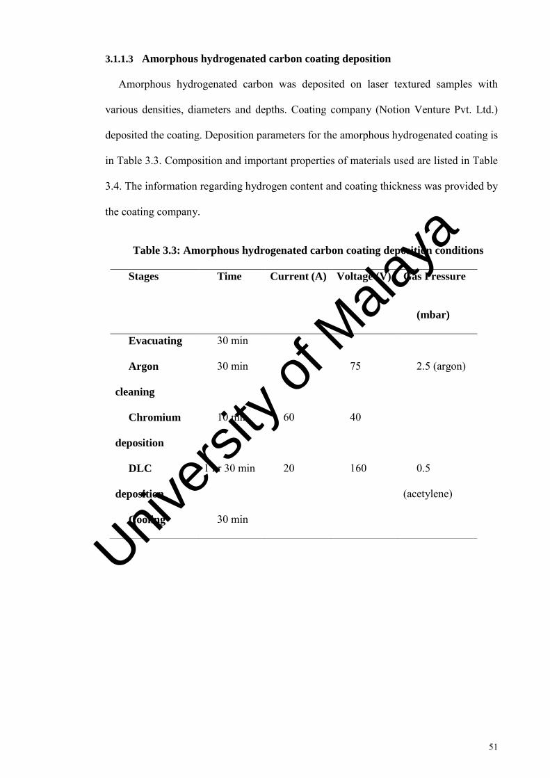
51
3.1.1.3 Amorphous hydrogenated carbon coating deposition
Amorphous hydrogenated carbon was deposited on laser textured samples with
various densities, diameters and depths. Coating company (Notion Venture Pvt. Ltd.)
deposited the coating. Deposition parameters for the amorphous hydrogenated coating is
in Table 3.3. Composition and important properties of materials used are listed in Table
3.4. The information regarding hydrogen content and coating thickness was provided by
the coating company.
Table 3.3: Amorphous hydrogenated carbon coating deposition conditions
Stages Time Current (A) Voltage (V) Gas Pressure
(mbar)
Evacuating 30 min
Argon
cleaning
30 min 75 2.5 (argon)
Chromium
deposition
10 min 60 40
DLC
deposition
1 hr 30 min 20 160 0.5
(acetylene)
Cooling 30 min
Univers
ity of
Mala
ya

52
Table 3.4: Composition and important properties of the tribological pair
Physical
Properties
Steel Ball Substrate number
1
Substrate number
2
Material AISI 52100 a-C:H ta-C
Composition C 0.98 %, Fe 96.5
%, Cr 1.30, Mn
0.250 %, Si 0.150
%,S ≤ 0.0250, P ≤
0.0250
20 at. % Hydrogen -
Roughness ~ 35 nm ~ 40 nm ~ 40 nm
Thickness 1.3-1.6 µm 1.3-1.6 µm
Hybrid magnetron sputtering (well known a physical vapor deposition) was employed
for depositing amorphous hydrogenated carbon coating. The main mechanism of this
technique can be explained as follows: High-energy ions created from discharge plasma
are bombarded on a target plate (cathode), targeted atoms are removed by the
bombardment of ions and thin film of these atoms is condensed on the substrate. Ion
bombardment also causes emission of secondary electrons from the target surface; plasma
is maintained by emitted secondary electrons. Magnets are placed parallel to target in
such a way that secondary electrons are trapped, which increase the probability of
electron collision and thus helps in sustaining plasma.
3.1.2 Mechanical properties
Hardness and elastic modulus of amorphous hydrogenated carbon coating was
determined using nano indenter (TI 750 UBI, Hysitron, Inc.). Adhesion between coating
Univers
ity of
Mala
ya

53
and substrate was determined using Rockwell C indentation test. The details of these tests
can be seen in section 3.5.
3.1.3 Tribological investigation
In order to identify the tribological performance variation with texture density,
diameter and depth, reciprocating sliding test rig (Ducom Instruments) was used. The
applied load, sliding frequency, stroke length, and test duration was 100 N, 5 Hz, 2 mm,
and 2 hours, respectively. This frequency and contact load was selected in order to ensure
boundary lubrication regime at the interface. Two-hour duration was selected in order to
have a measurable wear track. Similar duration for testing has been used by previous
studies (He et al. 2015). Poly alpha olefin (PAO) was used for tribological testing. PAO
was obtained from INEOS Pvt. Limited. The complete detail for the tribo-testing can be
seen in section 3.6. After tribological testing, the samples were washed with n-heptane
for characterization.
3.1.4 Surface characterization
Laser textured and un-textured amorphous hydrogenated carbon coated samples with
various texture density, diameter and depths were characterized before and after the trio-
testing using Profilometer (Veeco Dektak 150 profilometer), Scanning electron
microscope (SEM) (HITACHI, Model No. TM3030), Energy dispersive x-ray
spectroscopy (EDX) (HITACHI, Model No. TM3030), Atomic force microscopy (AFM)
(Q-ScopeTM 250/400, AMBIOS technology) and Raman's spectroscopy (Gloucestershire,
United Kingdom). The details of the equipment used for surface characterization can be
seen in section 3.7.
Univers
ity of
Mala
ya

54
Figure 3.2: Flow chart of research activities
3.2 Tribological behavior of textured and un-textured amorphous
hydrogenated carbon coating at various temperatures
The range of temperature was selected to simulate the actual engine conditions. In
order to analyze and compare the behavior of textured and un-textured amorphous
hydrogenated carbon coating at various temperatures, following steps were taken.
3.2.1 Sample Preparation
Two types of samples were prepared. One is un-textured coated designated as PAO-
C40 (C indicates coated but non-textured sample) and another is textured coated
designated as PAO-T40 (T indicates textured coated). In the designation PAO-C40,
“PAO” represents the lubricant used and “40” represents the temperature at which testing
was conducted. Sample TMP-C40 indicates un-textured coated samples tested at 40 ºC
in palm based TMP ester. The samples used have the dimension of 15mm by 15 mm.
Univers
ity of
Mala
ya
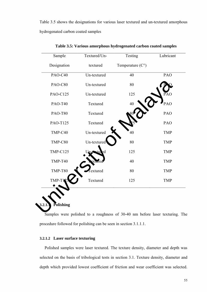
55
Table 3.5 shows the designations for various laser textured and un-textured amorphous
hydrogenated carbon coated samples
Table 3.5: Various amorphous hydrogenated carbon coated samples
Sample
Designation
Textured/Un-
textured
Testing
Temperature (C°)
Lubricant
PAO-C40 Un-textured 40 PAO
PAO-C80 Un-textured 80 PAO
PAO-C125 Un-textured 125 PAO
PAO-T40 Textured 40 PAO
PAO-T80 Textured 80 PAO
PAO-T125 Textured 125 PAO
TMP-C40 Un-textured 40 TMP
TMP-C80 Un-textured 80 TMP
TMP-C125 Un-textured 125 TMP
TMP-T40 Textured 40 TMP
TMP-T80 Textured 80 TMP
TMP-T125 Textured 125 TMP
3.2.1.1 Polishing
Samples were polished to a roughness of 30-40 nm before laser texturing. The
procedure followed for polishing can be seen in section 3.1.1.1.
3.2.1.2 Laser surface texturing
Polished samples were laser textured. The texture density, diameter and depth was
selected on the basis of tribological tests in section 3.1. Texture density, diameter and
depth which provided lowest coefficient of friction and wear coefficient was selected.
Univers
ity of
Mala
ya
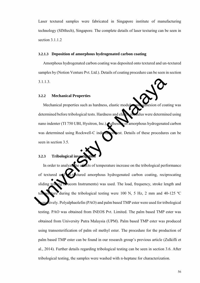
56
Laser textured samples were fabricated in Singapore institute of manufacturing
technology (SIMtech), Singapore. The complete details of laser texturing can be seen in
section 3.1.1.2
3.2.1.3 Deposition of amorphous hydrogenated carbon coating
Amorphous hydrogenated carbon coating was deposited onto textured and un-textured
samples by (Notion Venture Pvt. Ltd.). Details of coating procedure can be seen in section
3.1.1.3.
3.2.2 Mechanical Properties
Mechanical properties such as hardness, elastic modulus and adhesion of coating was
determined before tribological tests. Hardness and elastic modulus were determined using
nano indenter (TI 750 UBI, Hysitron, Inc.). Adhesion of amorphous hydrogenated carbon
was determined using Rockwell-C indentation test. Details of these procedures can be
seen in section 3.5.
3.2.3 Tribological investigation
In order to analyze the effects of temperature increase on the tribological performance
of textured and un-textured amorphous hydrogenated carbon coating, reciprocating
sliding test rig (Ducom Instruments) was used. The load, frequency, stroke length and
temperature during the tribological testing were 100 N, 5 Hz, 2 mm and 40-125 ºC
respectively. Polyalphaolefin (PAO) and palm based TMP ester were used for tribological
testing. PAO was obtained from INEOS Pvt. Limited. The palm based TMP ester was
obtained from University Putra Malaysia (UPM). Palm based TMP ester was produced
using transesterification of palm oil methyl ester. The procedure for the production of
palm based TMP ester can be found in our research group’s previous article (Zulkifli et
al., 2014). Further details regarding tribological testing can be seen in section 3.6. After
tribological testing, the samples were washed with n-heptane for characterization.
Univers
ity of
Mala
ya

57
3.2.4 Surface characterization
Surface characterization was conducted before and after the tribological investigation.
Characterization techniques used can be seen in section 3.7. In order to observe structural
changes in amorphous hydrogenated carbon coating due to temperature change, Raman
spectroscopy (Renishaw, United Kingdom) was used. SEM (HITACHI, Model No.
TM3030) and AFM (Q-ScopeTM 250/400, AMBIOS technology) were used to analyze
the surface of wear track. Profilometer (Veeco Dektak 150 profilometer) was used to
analyze the wear track. EDX (HITACHI, Model No. TM3030) was used to find the
chemical composition at the wear track.
3.3 Tribological behavior of textured and un-textured tetrahedral amorphous
carbon coating at various temperatures
The range of temperature was selected to simulate the actual engine conditions.
Following steps were taken in order to achieve the objective of analyzing the performance
of laser textured and un-textured tetrahedral amorphous carbon coating at various
temperatures.
3.3.1 Sample preparation
Two types of samples were created. Textured coated sample ta-C.PAO-T40 (“ta-C” is
the coating type, letters “PAO” indicates the lubricant tested, letter “T” indicates textured
coated sample and number “40” represents the temperature at which tribo-testing was
conducted) and un-textured coated sample ta-C. PAO-C40 (where C represents un-
textured coated sample). Similarly, ta-C.TMP-C40 and ta-C.TMP-T40 indicates that
TMP lubricant was used with un-textured and textured coating at 40 ºC, respectively.
Textured DLC coated samples have dimension of 15 mm by 15 mm. Table 3.6 shows the
designations for various laser textured and un-textured tetrahedral amorphous carbon
coated samples
Univers
ity of
Mala
ya

58
Table 3.6: Various laser textured and un-textured tetrahedral amorphous
carbon coated samples
Sample Designation Textured/Un-
textured
Testing
Temperature (C°)
Lubricant
ta-C.PAO-C40 Un-textured 40 PAO
ta-C.PAO-C80 Un-textured 80 PAO
ta-C.PAO-C125 Un-textured 125 PAO
ta-C.PAO-T40 Textured 40 PAO
ta-C.PAO-T80 Textured 80 PAO
ta-C.PAO-T125 Textured 125 PAO
ta-C.TMP-C40 Un-textured 40 TMP
ta-C.TMP-C80 Un-textured 80 TMP
ta-C.TMP-C125 Un-textured 125 TMP
ta-C.TMP-T40 Textured 40 TMP
ta-C.TMP-T80 Textured 80 TMP
ta-C.TMP-T125 Textured 125 TMP
3.3.1.1 Polishing of samples
Samples were polished to reduce surface roughness. Similar procedure was used as
described in section 3.1.1.1. Final surface roughness of samples was 30-40 nm.
3.3.1.2 Laser surface texturing
Surface textured samples were created using laser ablation. Laser surface texturing
was conducted in Singapore institute of manufacturing technology (SIMtech), Singapore.
The texture parameters which provided lowest coefficient of friction and wear coefficient
in section 3.1 were used in this section. Further details regarding laser surface texturing
can be seen in section 3.1.1.2.
Univers
ity of
Mala
ya

59
3.3.1.3 Deposition of tetrahedral amorphous carbon coating
Tetrahedral amorphous carbon coating was deposited by Notion Venture Pvt. Ltd. on
textured and un-textured samples. Deposition parameters for the coatings were not
provided by the company. Composition and important properties of materials used are
listed in Table 3.3. The information regarding hydrogen content and coating thickness
was provided by the coating company. Further details regarding deposition can be seen
in section 3.1.1.3.
3.3.2 Mechanical properties
Mechanical properties such as hardness, elastic modulus and adhesion of tetrahedral
amorphous carbon coating was determined using nano indentation (TI 750 UBI, Hysitron,
Inc.) and Rockwell C indentation. The details of these procedures can be seen in section
3.5.
3.3.3 Tribological investigation
Tribological behavior variation of laser textured tetrahedral amorphous carbon coating
with temperature in the presence of PAO and TMP ester was conducted using
reciprocating test rig (Ducom instruments). The load, frequency, stroke length and
temperature during the tribological testing were 100 N, 5 Hz, 2 mm and 40-125 ºC
respectively. As mentioned in section 3.2.3, Poly alpha olefin (PAO) and palm based
TMP ester was used for tribological testing. PAO lubricant was obtained from INEOS
Pvt. Ltd. The palm based TMP ester was obtained from University Putra Malaysia
(UPM). The details of tribological testing is mentioned in section 3.6. After tribological
testing, the samples were washed with n-heptane for characterization.
3.3.4 Surface characterization
Characterization of tetrahedral amorphous carbon coating (textured and un-textured)
was conducted using various technique. Profilometer (Veeco Dektak 150 profilometer)
Univers
ity of
Mala
ya

60
was used to analyze wear track, SEM (HITACHI, Model No. TM3030) and AFM (Q-
ScopeTM 250/400, AMBIOS technology) were used to observe the topography of wear
track, EDX (HITACHI, Model No. TM3030) was used to observe chemical composition
at the wear track and Raman spectroscopy (Renishaw, United Kingdom) was used to
analyze the structural changes. Details of these techniques can be observed in section
3.7.
3.4 Comparison of tribological properties of laser textured amorphous
hydrogenated carbon and tetrahedral amorphous carbon coating
A comparison was conducted in order to analyze whether laser textured amorphous
hydrogenated carbon is better or worse in tribological performance compared to laser
textured tetrahedral amorphous carbon coating. Coefficient of friction and wear
coefficient of amorphous hydrogenated carbon and tetrahedral amorphous carbon coating
were compared.
3.5 Mechanical properties of coatings
3.5.1 Adhesion of DLC coatings
Lifetime of coating highly depends upon the quality of adhesion between substrate and
coating. Working life of coating is reduced by poor adhesion. Therefore, for reliability
better adhesion is required. Number of methods have been introduced for evaluating the
quality of adhesion (Volinsky et al., 2002). Adhesion of DLC coatings was investigated
through a Rockwell C test. The classification of this test is based on the German standard
VDI 3198 and had been used previously by Ronkainen et al. to evaluate amorphous
hydrogenated and tetrahedral amorphous carbon coating adhesion (Ronkainen et al.,
1999). In this test, a standard Rockwell C hardness tester was used to assess Rockwell C
adhesion. The indentation causes layer damage adjacent to the boundary of the
indentation. After indentation, optical microscope was used to evaluate the indented
areas. Three indents were made on each sample, and the damage to the coating was
Univers
ity of
Mala
ya
61
compared with a defined adhesion strength quality shown in Figure 3.3. The types of
defects are classified as HF1 to HF6. HF1-HF4 defines sufficient adhesion whereas HF5
and HF6 indicated insufficient adhesion (Heinke et al., 1995). HF1 indicates the highest
adhesion, and HF6 indicates the lowest adhesion.
Figure 3.3: Failure modes for Rockwell C adhesion testing (Heinke et al.,
1995)
Univers
ity of
Mala
ya
62
3.5.2 Hardness and elastic modulus of DLC coatings
Recently, nano-indention technology has become popular for measuring hardness and
elastic modulus. The working principle of nano-indentation test can be described as
follow: a well-molded indenter, generally a Berkovich shaped diamond having ramped
load is applied vertically on the surface of component. As the indenter moves in the
surface, firstly, elastic then plastic deformations occur, and hardness of material can be
evaluated by measuring depth of residual indentation. A conventional microscope is
unable to show the depths of indentations having dimensions up to 10% of coating
thickness. Because of this reason during indentation, depth is measured constantly instead
of post assessment after indentation.
Hardness and elastic modulus of the amorphous hydrogenated carbon and tetrahedral
amorphous carbon coating were determined through nano-indenter (TI 750 UBI,
Hysitron, Inc.). A Berkovich indentor was used, and depth control function was used. It
is recommended that the indent depth should be less than 10 % of coating thickness, this
is to avoid the influence of the substrate (Austin, 2014). As coating thickness was around
1.3-1.6 µm, therefore, indent depth was kept at 80 nm. A load of 3 N for indentation. In
order to obtain a statistical representation, 10 indentations were performed for each
sample. Similar procedure has been used in (Austin, 2014). After indentation, elastic
modulus and hardness were obtained from the computer program integrated with the
nano-indentor.
3.6 Tribological testing
A reciprocating test rig (Ducom instruments) with a ball-on-plate configuration was
used to examine the friction and wear behavior of textured and un-textured DLC coatings.
Figure 3.4 shows the schematic diagram of reciprocating test rig. Measurement of friction
force during testing is also a common practice in such experimental works. Two main
Univers
ity of
Mala
ya

63
reasons of measuring friction are: (1) coefficient of friction is an important parameter in
all coating applications, and; (2) coating breakdown and lubrication conditions can be
identified by dramatic variations of friction. Friction and wear are described as a function
of a tribo-system (Kato, 2000).
Figure 3.4: Schematic representation of reciprocating test rig (Zulkifli et al.,
2013)
In order to identify the regime in which contact is operating, equation 3.1 for EHL
regime by Dowson and Higginson was used (Mistry et al., 2011; Winer & Peterson,
1980).
ℎ𝑚𝑖𝑛
𝑅′ = 1.79 (𝑈𝜂0
𝐸′𝑅′)0.68
(𝛼𝐸′)0.49 (𝑤
𝐸′𝑅′2)−0.073
3.1
Where ℎ𝑚𝑖𝑛 is representing minimum thickness of film (m). Symbol U shows the
entraining surface velocity (m/s), given as 𝑈 =𝑈𝑎 +𝑈𝑏
2, where Ua denotes the velocities of
counter ball, and Ub refers to the velocities of plate. Symbol 𝜂0 indicates the viscosity of
lubricant at atmospheric pressure (Pa.s). Symbol 𝐸′ represents reduced elastic modulus
(Pa) found through equation 1
𝐸′ =1
2(
1−𝑣𝑎2
𝐸𝑎+
1−𝑣𝑏2
𝐸𝑏), where ν is Poisson’s ratio and Ea and
Univers
ity of
Mala
ya

64
Eb represents the elastic modulus for corresponding ball and plate specimens. Symbol 𝑅′
denotes reduced radius of curvature (m) for a ball on flat configuration, such that 1
𝑅′ =
(1
𝑅𝑎𝑥+
1
𝑅𝑎𝑦), where Ra is the radius of curvature for x and y direction. 𝛼 is the pressure-
viscosity coefficient (m2/N) of lubricant, given as equation 𝛼 = (0.6 + 0.965 log10 𝜂0) ×
10−8. Symbol ‘W’ is representing applied normal load (N).
Lubrication regime was determined by fluid film thickness parameter ‘λ’ (Equation
3.2). Fluid film thickness parameter ‘λ’ is defined as the ratio of fluid film thickness ‘h’
and surface roughness ‘σ’. Equation 3.3 provides composite surface roughness, where σ1
and σ2 are root mean square roughness of interacting surfaces. In order to identify the
regime, value of ‘λ’ should be as follows:
1. If the value of λ is less than 1, boundary lubrication is present.
2. If the value is 1 ≤ 𝜆 ≤ 3, mixed or elastohydrodynamic lubrication exists.
3. If the value λ is greater than 3, hydrodynamic lubrication is present.
𝜆 =ℎ𝑚𝑖𝑛
𝜎 3.2
𝜎 = 𝜎12 + 𝜎2
2 3.3
Before each test was performed, the ball and the DLC coated plate were cleaned with
acetone in an ultrasonic bath. After the test was conducted, the samples were cleaned with
n-heptane and stored in desiccators until surface characterization.
After the tribological testing, volume loss of steel balls was determined by mass loss
method. After the removal of the tribo-layers (if any), the wear rate was calculated by V
= k.F.s (Archard equation), where symbol V is the wear volume, symbol k is the specific
Univers
ity of
Mala
ya

65
wear rate coefficient, symbol F is the normal load and symbol s is the total distance
travelled.
3.6.1 Lubricants used for tribological testing
Polyalphaolefin (PAO) and palm based TMP ester was used for tribological testing.
PAO was obtained from INEOS Pvt. Ltd. The palm based TMP ester was obtained from
University Putra Malaysia (UPM). Palm based TMP ester was produced using
transesterification of palm oil methyl ester. The procedure for the production of palm
based TMP ester can be found in our research group’s previous article (Zulkifli et al.,
2014). The viscosity of obtained PAO and TMP at 40 °C was 65.1 and 40.01 cst
respectively.
In boundary lubrication conditions, the micro asperities of the surfaces are in contact;
that is why the rheological properties such as viscosity do not play an important role in
tribological characteristics. In the boundary lubrication regime, the interaction between
friction surfaces and interactions of friction surfaces and lubricant additives dominated
the tribological behavior (Hironaka, 1984). As in this research work boundary lubrication
was considered and lubricants without additives were used, therefore, the variation in
friction and wear behavior is mostly governed by micro textures and coating type.
3.7 Characterization techniques
3.7.1 Profilometer
Surface roughness of ball and plate was measured with Veeco Dektak 150
profilometer. It is a surface profilometer, which uses contact profilometer technology to
take measurements of surface topography and roughness.
Univers
ity of
Mala
ya

66
3.7.2 Scanning electron microscopy (SEM)
A scanning electron microscope (SEM) (HITACHI, Model No. TM3030) operated at
10 kV, was used for wear track investigation. Scanning electron microscopy (SEM)
solves many issues encountered in optical microscopy. In SEM, electron beam is
bombarded on the surfaces, and images are generated by collecting emitted
electromagnetic radiations. Electron gun is used to generate the electron, which is
directed towards a specific point of sample surface, after passing through a number of
electromagnetic lenses (Handbook for Analytical Methods for Materials, 2014). The
wavelength of electron beams is shorter than reflected light, so electron microscopy has
greater resolution compared to optical microscopy. Maximum theoretical resolution that
can be achieved in SEM is less than 1 nm. However, spot size of the beam (area which is
affected by electrons) limits the practical resolution (Handbook for Analytical Methods
for Materials, 2014).
3.7.3 Energy Dispersive X-Ray spectroscopy (EDX)
Energy dispersive X-ray spectroscopy (HITACHI, Model No. TM3030) has been
employed for identification of chemical composition of DLC coatings after tribological
testing. EDX characterizes the x-rays emitted from the surface bombarded with electron
beams. When high-energy electrons strike the targeted atom, inner shell electrons are
ejected leaving a vacant space called electron hole. An outer shell electron of higher
energy fills this hole, and energy is released in the form of x-ray (Handbook for Analytical
Methods for Materials, 2014). As the difference of energy between shells of an atom can
be quantized by the energy of emitted x-ray, therefore, these rays can be used to
characterize the element from which they are emitted.
Univers
ity of
Mala
ya

67
3.7.4 Raman Spectroscopy
Raman spectra was collected with an InVia Raman microscope (Gloucestershire,
United Kingdom) with laser wavelength of 514 nm. A 10% laser power was used to
minimize the influence of the substrate in the measurements. Three Raman measurements
were taken for each sample to present a statistical representation of results so that the
inaccuracies resulting from peak fitting could be minimized.
In Raman's spectroscopy, light is used to extract structural information of materials
using Raman's effect. Raman spectroscopy is a standard technique for characterizing the
carbon-based materials. When a light beam strikes the carbon substances, large number
of photons gets elastically scattered and no energy shift is observed. However, some
molecules of samples are excited by a small ratio of striking photons, and thus they are
scattered inelasticity. Raman effect can be described briefly as the change in the level of
energy exhibited by inelasticity scattered light. These energy shifts occur due to atomic
arrangement of complex carbon structures (Ferraro, 2003). In Raman's spectrum,
intensity of scattered light is plotted against the energy. In case of amorphous carbon,
Raman spectra are specified by peak centered around D band (1300-1380 cm-1), and peak
centered around G band (1520-1580 cm-1). The D band is linked to breathing mode of sp2
sites only for carbon chains, while stretch vibrations of any pair of sp2 sites derive the G
band. Structural information from Raman's spectra can be extracted by following general
rules. The shift in the G peak and increase in the ID/IG ratio indicates an increase as the
sp2 fraction in the DLC film (Casiraghi et al., 2005; Ferrari & Robertson, 2000).
Deconvolution of the Raman spectra into D and G peaks was conducted using licensed
version of OriginPro 8.5.1 software. This software uses Gaussian function to fit peaks,
which is present under multiple peak fitting tab.
Univers
ity of
Mala
ya

68
3.7.5 Atomic force microscopy (AFM)
Atomic force microscopy (Q-ScopeTM 250/400, AMBIOS technology) was used to
further analyze the wear track surface morphology. AFM test was performed to measure
the changes in surface roughness of samples after tribological testing. The AFM scan was
conducted for 25 µm × 25 µm area of the wear track.
In AFM, a micro scale cantilever is drawn across the surface of sample; it is usually
done by using silicon and a tip radius of nanometers scale. When tip comes in close
contact with the surface of samples, surface forces displace it. A laser is spotted at a
particular angle on the rear surface of cantilever and motion of reflected laser spot is
observed on photodiode arrays to determine the displacement. A very high atomic level
resolution is achieved by controlling the position of probe with the help of piezoelectric
actuators. A three-dimensional image of surface geometry can be built by quantifying the
displacement of cantilever (Handbook for Analytical Methods for Materials, 2014). AFM
is normally adopted for scan areas of small sizes.
Univers
ity of
Mala
ya

69
CHAPTER 4: RESULTS AND DISCUSSION
4.1 Coating and lubricant properties
4.1.1 Hardness and Elastic Modulus
Hardness and elastic modulus of the amorphous hydrogenated carbon and tetrahedral
amorphous carbon coating were determined through nano-indentation testing. Nano
hardness and elastic modulus of DLC coatings can be seen in Table 4.1. Generally
amorphous hydrogenated carbon films exhibit hardness of 15 to 50 Gpa, whereas
tetrahedral amorphous carbons are harder with hardness range of 30-80 Gpa (Hauert,
2004). In this study, tetrahedral amorphous carbon coating showed higher hardness
compared to be amorphous hydrogenated carbon coating. The higher hardness of
tetrahedral coating can be related to higher sp3 content (Bewilogua & Hofmann, 2014;
Robertson, 1991; Ronkainen & Holmberg, 2008). Hardness/elastic modulus (H/E) ratio
was calculated in order to understand the wear behavior of coatings. As H/E ratio is an
indication of wear resistance of a coating (Austin, 2014). The H/E ratio was 0.12 and 0.14
for amorphous hydrogenated carbon and tetrahedral amorphous carbon coating.
Table 4.1: Hardness and elastic modulus of amorphous hydrogenated carbon
and tetrahedral amorphous carbon coating
Coating Hardness
(GPa)
Elastic Modulus
(GPa)
H/E Ratio
a-C:H 18.4 ± 2.2 158.5 ± 14.4 0.12
ta-C 40.5 ± 3.5 280.8 ± 18.2 0.14
Univers
ity of
Mala
ya
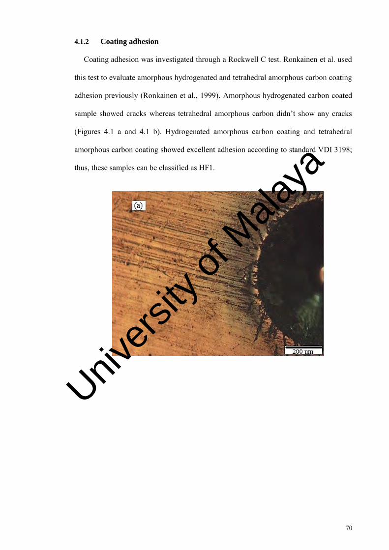
70
4.1.2 Coating adhesion
Coating adhesion was investigated through a Rockwell C test. Ronkainen et al. used
this test to evaluate amorphous hydrogenated and tetrahedral amorphous carbon coating
adhesion previously (Ronkainen et al., 1999). Amorphous hydrogenated carbon coated
sample showed cracks whereas tetrahedral amorphous carbon didn’t show any cracks
(Figures 4.1 a and 4.1 b). Hydrogenated amorphous carbon coating and tetrahedral
amorphous carbon coating showed excellent adhesion according to standard VDI 3198;
thus, these samples can be classified as HF1.
Univers
ity of
Mala
ya

71
Figure 4.1 continued: The micrograph of the Rockwell C-indentation tests (a)
amorphous hydrogenated carbon coating (b) tetrahedral amorphous coating
4.2 Effect of change in texture density, diameter and depth on tribological
behavior of amorphous hydrogenated carbon coating
Effect of change in tribological behavior of amorphous hydrogenated carbon coating
with dimple densities, diameters and depths was conducted using samples shown in
Figure 4.2 and Figure 4.3. Figure 4.2 shows the SEM images of various dimple densities
and diameters, whereas Figure 4.3 shows the two-dimensional profiles of various dimple
depths.
Univers
ity of
Mala
ya

72
Diameter = 50 µm
Density = 30 %
Depth = 6 µm
Diameter = 50 µm
Density = 20 %
Depth = 6 µm
Diameter = 50 µm
Density = 10 %
Depth = 6 µm
(a)
(b)
(c)
Univers
ity of
Mala
ya

73
Diameter = 100 µm
Density = 30 %
Depth = 6 µm
Diameter = 100 µm
Density = 20 %
Depth = 6 µm
Diameter = 100 µm
Density = 10 %
Depth = 6 µm
(d)
(e)
(f)
Univers
ity of
Mala
ya

74
Diameter = 150 µm
Density = 30 %
Depth = 6 µm
Diameter = 150 µm
Density = 20 %
Depth = 6 µm
(g)
(h)
Univers
ity of
Mala
ya

75
Diameter = 150 µm
Density = 10 %
Depth = 6 µm
Figure 4.2 continued: SEM topographical images of amorphous hydrogenated
carbon coated textured samples (a) Dn30Di50Dp6, (b) Dn20Di50Dp6, (c)
Dn10Di50Dp6, (d) Dn30Di100Dp6, (e) Dn20Di100Dp6, (f) Dn10Di100Dp6, (g)
Dn30Di150Dp6, (h) Dn20Di150Dp6 and (i) Dn10Di150Dp6
0 50 100 150 200 250 300-30
-25
-20
-15
-10
-5
0 Dn20Di100Dp6 Dn20Di100Dp15 Dn20Di100Dp30
Dep
th (
m)
Diameter (m)
Figure 4.3: 2-dimensional profiles of amorphous hydrogenated carbon coated
textured samples with different dimple depths
(i)
Univers
ity of
Mala
ya

76
4.2.1 Friction and wear behavior
Figure 4.4 shows the coefficient of friction behavior of un-textured and textured
amorphous hydrogenated carbon coated samples as a function of reciprocating sliding
time. The average coefficient of friction values is shown in Figure 4.5. Average
coefficient of friction was taken from 1600 seconds. Coefficient of friction is minimum
at 30 % dimple density compared to 10 % density for all combinations of diameters and
depths. In the case of 20 % dimple density, most of the dimple diameters and depth's
combination showed the higher coefficient of friction than 30 % and 10 % dimple density
except for the sample Dn20Di100Dp6. Sample Dn20Di100Dp6 yielded the lowest
average coefficient of friction of 0.084 among all the tested samples, whereas a sample
Dn20Di150Dp30 showed the highest coefficient of friction of 0.1406. Un-textured
sample a-C:H-Untex showed the average coefficient of friction of 0.11. Some samples in
various dimple densities showed a lower average coefficient of friction than a-C:H-
Untex. Dimple's diameter of 100 µm showed the lower average coefficient of friction
than 50 and 150 µm at all densities tested. With respect to dimple depth, 6 µm showed
the lower average coefficient of friction regardless of dimple diameters and densities. The
results indicate that the dependence of frictional behavior is on appropriate combination
of dimple density, diameter and depth.
Univers
ity of
Mala
ya

77
Univers
ity of
Mala
ya

78
Figure 4.2 continued: Change in coefficient of friction of amorphous
hydrogenated carbon coated samples with time (a) dimple density 10 %, (b)
dimple density 20 % and (c) dimple density 30 %
Univers
ity of
Mala
ya
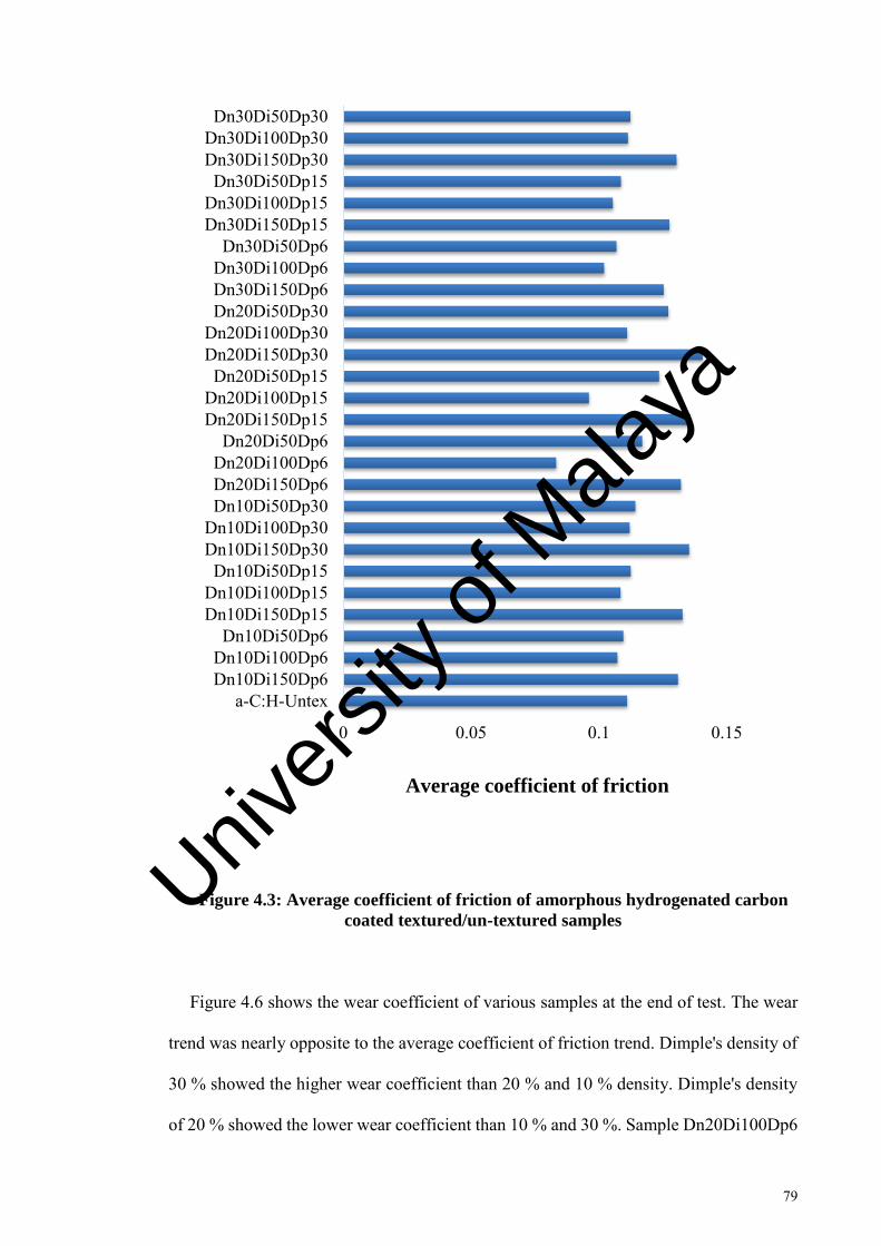
79
Figure 4.3: Average coefficient of friction of amorphous hydrogenated carbon
coated textured/un-textured samples
Figure 4.6 shows the wear coefficient of various samples at the end of test. The wear
trend was nearly opposite to the average coefficient of friction trend. Dimple's density of
30 % showed the higher wear coefficient than 20 % and 10 % density. Dimple's density
of 20 % showed the lower wear coefficient than 10 % and 30 %. Sample Dn20Di100Dp6
0 0.05 0.1 0.15
a-C:H-UntexDn10Di150Dp6Dn10Di100Dp6Dn10Di50Dp6
Dn10Di150Dp15Dn10Di100Dp15Dn10Di50Dp15
Dn10Di150Dp30Dn10Di100Dp30Dn10Di50Dp30Dn20Di150Dp6Dn20Di100Dp6Dn20Di50Dp6
Dn20Di150Dp15Dn20Di100Dp15Dn20Di50Dp15
Dn20Di150Dp30Dn20Di100Dp30Dn20Di50Dp30Dn30Di150Dp6Dn30Di100Dp6Dn30Di50Dp6
Dn30Di150Dp15Dn30Di100Dp15Dn30Di50Dp15
Dn30Di150Dp30Dn30Di100Dp30Dn30Di50Dp30
Average coefficient of friction
Univers
ity of
Mala
ya

80
showed the lowest and Dn30Di150Dp30 showed the highest wear coefficient. Dimple's
diameter of 100 µm showed the lowest wear coefficient at all dimple densities tested. If
the diameter exceeded 100 µm, wear performance degraded (as shown in Figure 4.6). The
wear results also indicated that when the depth was increased from 6 - 30 µm (for various
densities and diameters), the wear coefficient increases. The wear coefficient results also
indicate that wear resistance of the amorphous hydrogenated carbon coating can be
improved with an optimum value of dimple parameters.
Figure 4.4: Wear coefficient of amorphous hydrogenated carbon coated
textured/un-textured samples after tribological testing
0 50 100 150
a-C:H-UntexDn10Di150Dp6Dn10Di100Dp6Dn10Di50Dp6
Dn10Di150Dp15Dn10Di100Dp15Dn10Di50Dp15
Dn10Di150Dp30Dn10Di100Dp30Dn10Di50Dp30Dn20Di150Dp6Dn20Di100Dp6Dn20Di50Dp6
Dn20Di150Dp15Dn20Di100Dp15Dn20Di50Dp15
Dn20Di150Dp30Dn20Di100Dp30Dn20Di50Dp30Dn30Di150Dp6Dn30Di100Dp6Dn30Di50Dp6
Dn30Di150Dp15Dn30Di100Dp15Dn30Di50Dp15
Dn30Di150Dp30Dn30Di100Dp30Dn30Di50Dp30
Wear Coefficient (10-8 mm3 N-1 m-1 )
Steel Ball a-C:H coated plate
Univers
ity of
Mala
ya

81
The fluid film thickness ratio between the ball on flat contact calculated by using the
Dowson and Higginson equation for elastrohydrodynamic lubrication (Mistry et al.,
2011; Winer & Peterson, 1980) was found to be less than 1. The film thickness ratio is
the ratio of minimum film thickness and composite surface roughness (Mistry et al., 2011;
Winer & Peterson, 1980). When the film thickness ratio is lower than 1, the contact
operates in boundary lubrication. Under the boundary conditions considered in the
present study, the friction and wear variation has been thought to be only due to dimple
density, diameter and depth variation. Due to the relative movement, the lubricant stored
in the dimples can be drawn up, which facilitates enhancement in tribological
performance (Amanov, et al., 2013). However, it was observed in the present study that
this enhancement depends upon the selection of appropriate dimple diameter relative to
the contact width, density and depth. The lower coefficient of friction of Dn20Di100Dp6
in the boundary regime can be attributed to the lubricant supplying and wear debris
trapping ability of optimum dimple parameters. Reduction in coefficient of friction at
particular dimple parameters due to lubricant reinforcement ability of textures has been
noticed previously (Ding et al., 2010).
In the case of textured ceramic and steel materials (uncoated), Wakuda et al. found
that with the increase in texture density from 7.5 % to 30 %, coefficient of friction
increases (Wakuda et al., 2003). Whereas in our investigation it was observed that 30%
density showed lower coefficient of friction than 10 % density. This difference can be
due to graphitization phenomenon of DLC coated substrate. The effect of increase in
graphitization with density and diameter is discussed in section 4.2.2.2.
At 20 % dimple density, when dimple diameter is changed and depth is kept at 6 µm,
Dn20Di100Dp6 yielded the lowest coefficient of friction of 0.083, whereas sample
Univers
ity of
Mala
ya

82
Dn20Di150Dp6 showed the highest average coefficient of friction of 0.132. Textured
samples (Dn20Di150Dp6 and Dn20Di50Dp6) exhibited higher average coefficient of
friction of 0.132, 0.117, respectively, compared with un-textured sample (a-C:H-Untex)
with coefficient of friction of 0.111 (as shown in Figure 4.6). The samples where depth
was kept at 15 µm and diameter was varied from 50-150 µm, sample Dn20Di100Dp15
showed lowest average coefficient of friction of 0.096. The samples Dn20Di150Dp15
and Dn20Di50Dp15 showed higher coefficient of friction of 0.136 and 0.124 compared
to a-C:H-Untex. As the depth was further increased to 30 µm and diameter was varied
from 50-150 µm, Dn20Di100Dp30 showed lower coefficient of friction of 0.111
compared to Dn20Di150Dp30 and Dn20Di50Dp30. Among all the samples tested at 20
% density, Dn20Di100Dp6 showed the lowest average coefficient of friction. The
average coefficient of friction behavior shows that at an appropriate dimple diameter
regardless of dimple depth value, reduction in coefficient of friction can be achieved. The
results also show that increasing or decreasing dimple diameter from optimum value can
have negative affect on coefficient of friction. At 10 and 30 % density, similar to 20 %
density when dimple diameter is varied from 100 µm, coefficient of friction and wear
coefficient increases.
The optimum dimple diameter depends on contact width-to-dimple diameter ratio
(Vilhena et al., 2009). At a contact load of 100 N, Hertz contact width is approximately
270 µm. At an optimum dimple depth of 6 µm and density of 20 %, if the dimple diameter
is much smaller (50 µm in the sample Dn20Di50Dp6) compared to contact width, the
coefficient of friction behavior of textured sample is almost similar to sample a-C:H-
Untex. An optimum dimple diameter relative to contact width for point contacts has been
noted by Vilhena et al. (2006) in uncoated steel material investigation. Vilhena et al.
(2006) suggested that contact load per unit area, coefficient of friction, and wear rate
increase if dimple diameter and contact width are nearly similar, as in the case of sample
Univers
ity of
Mala
ya
83
Dn20Di150Dp6; this may explain the increase in the coefficient of friction and wear rate
as dimple diameter exceeds 100 µm.
In the case of samples, where dimple depth is changed by keeping density and diameter
constant, the depth of 6 µm showed the lowest average coefficient of friction (Figure 4.5).
The average coefficient of friction increases as dimple depth increases. Wear trend is
similar to the average coefficient of friction trend. This increase in the coefficient of
friction and wear is due to the change in dimple depth when diameter and density are held
constant. At dimple density of 20 % and diameter of 100 µm (Figure. 4.4 b), at the start
of the test, the three samples (Dn20Di100Dp6, Dn20Di100Dp15 and Dn20Di100Dp30)
exhibited similar coefficient of frictions; as the test progressed, samples
(Dn20Di100Dp15 and Dn20Di100Dp30) showed an increase in the coefficient of
friction. In the case of sample Dn20Di100Dp30, a sudden increase in the coefficient of
friction was observed at 2400 s (Figure. 4.4 b). In the case of sample Dn20Di100Dp15,
this condition occurred after 3600 s. After 5000 s, the coefficient of friction of sample
Dn20Di100Dp30 became unstable (Figure. 4.4 b). This instability can be due to metal-
to-metal contact as amorphous hydrogenated carbon coating delaminated, this wear
behavior will be discussed in section 4.2.2.1. Thus, a possible situation is that as the
dimple depth increases, the deep dimples serve as micro traps of lubricant and remove
the remaining oil from their vicinity, thus changing the lubrication regime from the
boundary to be starved (Ryk et al., 2002). This abrupt increase in the coefficient of friction
due to oil starvation is consistent with previous literature (Demas et al., 2005; Mishra &
Polycarpou, 2011).
Tribological performance is decreased as dimple depth increases in non-conformal
contacts in an elastrohydrodynamic regime (EHL) regime (Mourier et al., 2006). Mourier
et al. found that an increase in dimple depth reduces local film thickness in an EHL regime
Univers
ity of
Mala
ya
84
under rolling-sliding conditions. Moreover, lubricant film thickness may even collapse if
dimples are very deep. By contrast, lubricant film thickness can be significantly enhanced
if dimples are shallow; thus, reducing friction and wear (Mourier et al., 2006). In this
study, it was found that in the case of the boundary lubrication regime, an increase in
dimple depth reduces the lubricant presence to such extent that contact becomes starved.
Increasing in the coefficient of friction due to oil starvation has been noticed previously
(Ryk et al., 2002). If the contact is starved, deep dimples become oil traps, which make
the contact more starved; thus, increasing coefficient of friction (Ryk et al., 2002).
4.2.2 Various textured amorphous hydrogenated carbon coating characterization
4.2.2.1 SEM/EDX and AFM analysis
Figure 4.7 shows the SEM micrographs of the amorphous hydrogenated carbon coated
samples. Sample Dn10Di100Dp6 and Dn30Di100Dp6 showed irregular delamination at
the wear track whereas Dn20Di100Dp6 shows only polishing wear. Sample a-C:H-Untex
also showed delamination at the wear track. EDX results can be seen in Table 4.2. Higher
increase in atomic percentage of Fe and Cr can be observed in case of Dn10Di100Dp6,
Dn30Di100Dp6 and a-C:H-Untex (Figures 4.7a, 4.7c and 4.7h). This indicates that
delamination occurred due to which interlayer was exposed. Increase in atomic
percentage of Cr has been observed in case of Dn20Di100Dp6 whereas small change in
Fe was observed. The EDX elemental analysis also confirms that at 10 % and 30 %
densities, delamination occurs whereas polishing wear occurs at 20 % density. The
instability in the coefficient of friction trend with time for samples Dn10Di100Dp6 and
Dn30Di100Dp6 (Figures 4.4 a and 4.4 c) can be due to delamination at the wear track,
whereas a sample Dn20Di100Dp6 (Figure 4.4 b) showed the smooth and stable
coefficient of friction trend due to only polishing wear.
Univers
ity of
Mala
ya
85
Samples where dimple density and depth were kept at 20 % and 6 µm and diameter
were changed from 50 - 150 µm; Dn20Di50Dp6 and Dn20Di150Dp6 showed irregular
delamination at the wear track (Figures 4.7 d and 4.7 e). Additionally, abrasive wear
marks can be observed at the wear track of Dn20Di50Dp6 and Dn20Di150Dp6 (Figures
4.7 d and 4.7 e). This behavior shows that if dimple density is optimum and dimple
diameter is not optimum, wear particle capturing ability of textures is less. EDX elemental
analysis of Dn20Di50Dp6 and Dn20Di150Dp6 show the higher increase in Fe and Cr
compared to Dn20Di100Dp6. The instability in the coefficient of friction trend of
Dn20Di50Dp6 and Dn20Di150Dp6 can be due to abrasive wear and coating delamination
(Figures 4.4 a and 4.4 c).
Figures 4.7 b, 4.7 f, and 4.7 g show the SEM images of the amorphous hydrogenated
carbon coated samples from various dimple depths at dimple density of 20 % and dimple
diameter of 100 µm after friction testing. Sample Dn20Di100Dp15 (Figure 4.7 f)
exhibited irregular coating delamination, whereas a sample Dn20Di100Dp30 (Figure 4.7
g) showed nearly complete coating delamination. Spallation and delamination are shown
in the case of Dn20Di100Dp15. When the coating is present, but it is loosely bounded to
the surface, the phenomenon is called spallation, where as in delamination the coating is
removed from the surface. Spallation phenomenon comes before delamination. Once the
adhesion of coating is gone, coating spalls. The EDX of the samples is listed in Table
4.2; Fe and Cr increased in the case of samples Dn20Di100Dp15 and Dn20Di100Dp30
compared to Dn20Di100Dp6. The abrupt increase in the coefficient of friction trend
Dn20Di100Dp30 at 5000 s can be due to excessive coating delamination (Figure 4.4 b).
SEM and EDX results indicate that depth of the dimples also has the profound effect on
the wear behavior of amorphous hydrogenated carbon coating.
Univers
ity of
Mala
ya

86
Univers
ity of
Mala
ya

87
Univers
ity of
Mala
ya

88
Univers
ity of
Mala
ya

89
Univers
ity of
Mala
ya

90
Figure 4.5 continued: SEM images of wear track after friction testing (a)
Dn10Di100Dp6, (b) Dn20Di100Dp6, (c) Dn30Di100Dp6, (d) Dn20Di50Dp6, (e)
Dn20Di150Dp6, (f) Dn20Di100Dp15, (g) Dn20Di100Dp30, (h) a-C:H-Untex and
(i) Dn30Di150Dp6
Wear track surface profile was investigated through AFM imaging (Figure 4.8). Figure
4.9 shows the average surface roughness of un-textured sample and textured samples with
varying dimple density, diameter and depth. The surface roughness of the polished
sample was approximately 30-40 nm. Lowest average roughness was shown by 20 %
dimple density compared to 10 % and 30 % density at 6 µm dimple depth and 100 µm
diameter. However, sample with 30 % dimple density showed lower roughness than 10
% dimple density. The lower average roughness of 20 % density is due to polishing wear.
This also represents that wear particle capturing ability was higher in this case. The
morphological characteristics of wear track of sample Dn20Di100Dp6 (Figure 4.8 b)
indicated that asperities were polished; thus, surface roughness was further reduced, and
a smooth surface was obtained. The microgrooves in the case of sample Dn10Di100Dp6
(Figure 4.8 a) was more evident than Dn30Di100Dp6 (Figure 4.8 c). This phenomenon
may be caused by the trapped wear particles that scratched the surface during sliding; this
Univers
ity of
Mala
ya

91
has been observed previously (Amanov et al., 2013). The reason for this behavior shown
by 10 % dimple density can be due to the higher distance between the dimples, which
reduces the chance for capturing wear particles by the textures compared to 20 % and 30
% dimple density at 100 µm dimple diameter.
Figures 4.8 b, 4.8 d and 4.8 e shows the samples with various dimple diameters at 20
% dimple density. Lowest average roughness was shown by Dn20Di100Dp6 compared
to Dn20Di50Dp6 and Dn20Di150Dp6 (Figure 4.9). The lower surface roughness
indicates that polishing of surface roughness occurred. Indeed, the dimples of sample
Dn20Di100Dp6 can remove wear particles from the wear track to prevent further wear;
by contrast, other samples with various dimple diameters failed to efficiently remove
wear particles.
Figures 4.8 b, 4.8 f, and 4.8 g showed AFM images samples from different dimple
depths. Sample Dn20Di100Dp6 shows the lower average surface roughness than samples
Dn20Di100Dp15 and Dn20Di100Dp30 (Figure 4.9). The surface morphological
characteristics of samples Dn20Di100Dp15 and Dn20Di100Dp30 (Figures 4.8 f and 4.8
g) show lower abrasive wear marks than those of sample a-C:H-Untex (Figure 4.8 h).
This result indicated that the wear particle capturing ability of dimples sustained by
maintaining an optimum dimple density and diameter, even by increasing dimple depth.
Thus, the mode of wear in the case of samples Dn20Di100Dp6, Dn20Di100Dp15 and
Dn20Di100Dp30 is mainly adhesive wear.
Univers
ity of
Mala
ya

92
Univers
ity of
Mala
ya

93
Univers
ity of
Mala
ya

94
Univers
ity of
Mala
ya

95
Figure 4.6 continued: AFM images of textured amorphous hydrogenated
carbon coated samples (a) Dn10Di100Dp6, (b) Dn20Di100Dp6, (c)
Dn30Di100Dp6, (d) Dn20Di50Dp6, (e) Dn20Di150Dp6, (f) Dn20Di100Dp15, (g)
Dn20Di100Dp30 and (h) a-C:H-Untex
Univers
ity of
Mala
ya

96
Figure 4.7: Average surface roughness values for un-textured/textured
amorphous hydrogenated carbon coated samples
Scratch marks indicating abrasive wearing were observed on counter surface ball that
rubbed against sample a-C:H-Untex (Figure 4.10 a) compared with counter surface ball
that rubbed against Dn20Di100Dp6 (Figure 4.10 b). This confirms that wear particles
were captured by the textures. Figure 4.6 shows the wear coefficient of the steel ball that
rubbed against various samples. The lower wear coefficient is found in the case of sample
Dn20Di100Dp6 counter ball compared to a-C:H-Untex. Raman spectroscopy revealed
that graphitization rate in the case of sample Dn20Di100Dp6 was lower than that in other
samples (Figure 4.11). Therefore, the reduction in wear of sample Dn20Di100Dp6
counter ball was mainly caused by texture mechanisms.
0 20 40 60
a-C:H-Untex
Dn10Di100Dp6
Dn20Di150Dp6
D20Di100Dp6
Dn20Di50Dp6
Dn20Di100Dp15
Dn20Di100Dp30
Dn30Di100Dp6
Average Surface Roughness (nm)
Univers
ity of
Mala
ya

97
Figure 4.8: SEM images of steel balls which rub against (a) a-C:H-Untex (b)
Dn20Di100Dp6
Table 4.2: EDX analysis of un-textured/textured coated samples
Specimen Elements (Atomic %)
C O Cr Fe Si Mn
Abrasive wearing
No abrasive wearing
Univers
ity of
Mala
ya

98
a-C:H-as
deposited
96.27 0.56 2.83 0.34 - -
a-C:H-Untex 80.81 1.10 10.19 7.90 - -
Dn20Di50Dp6 82.32 1.67 11.09 4.92 - -
Dn20Di100Dp6 95.41 0.43 3.65 0.51 - -
Dn20Di150Dp6 78.81 1.31 13.19 6.69 - -
Dn20Di100Dp15 87.01 1.35 8.98 2.66 - -
Dn20Di100Dp30 39.04 2.10 13.34 44.87 0.42 0.23
Dn10Di100Dp6 84.23 1.99 8.45 5.33 - -
Dn30Di100Dp6 89.71 0.89 6.81 2.59 - -
4.2.2.2 Raman analysis
The lowest average coefficient of friction of sample Dn20Di100Dp6 can be attributed
to graphitization, surface texturing, or both. A thin graphitic transfer film forms on a
counter surface because of coated plate graphitization (Liu et al., 1996); as a result,
coefficient of friction is decreased because the low shear strength of basal planes provides
easy slip between tribo-pairs (Sánchez-López et al., 2003). Raman spectroscopy was
performed to investigate whether or not graphitization is the main reason for the improved
performance of sample Dn20Di100Dp6. As 100 µm diameter and 6 µm depth has shown
better coefficient of friction and wear coefficient results than other dimple dimeters and
depths that is why for comparison purposes Raman spectra of Dn10Di100Dp6,
Dn20Di100Dp6 and Dn30Di100Dp6 were collected.
Figure 4.11 illustrates amorphous hydrogenated carbon coating spectrums for various
textured/un-textured samples before and after friction test. For quantitative analysis, the
Raman spectra was fitted into D and G peaks. The G peak indicates the stretching
vibration of sp2 carbon in C=C chains and aromatic ring, whereas the D peak indicates
Univers
ity of
Mala
ya

99
the breathing mode of sp2 carbon in the aromatic rings (Casiraghi et al., 2005). The ID/IG
ratio and the G peak position can be generally used to characterize sp3/sp2 bonding ratio
(Casiraghi et al., 2005). The shift in G peak and increase in ID/IG ratio indicate an increase
in sp2 fraction (graphite) in the DLC film (Ferrari & Robertson, 2000).
The samples Dn30Di100Dp6, Dn20Di100Dp6 and Dn10Di100Dp6 showed G peak
shift from 1554 to 1564, 1557 and 1560, respectively. The samples Dn30Di100Dp6,
Dn20Di100Dp6 and Dn10Di100Dp6 showed ID/IG ratio increase from 1.32 to 1.50, 1.33
and 1.45, respectively. Higher ID/IG ratio and G peak shift has been observed in the case
of Dn30Di100Dp6 after testing compared to Dn20Di100Dp6 and Dn10Di100Dp6. These
results indicate that with the change in dimple density, the graphitization behavior
changes. Lower average coefficient of friction in the case of Dn30Di100Dp6 than
Dn10Di100Dp6 can be due to higher graphitization. However, Dn20Di100Dp6 showed
lower average coefficient of friction than Dn30Di100Dp6. This result indicates that the
lower average coefficient of friction of Dn20Di100Dp6 is related to mechanism of
textures rather than graphitization. Due to graphitization, the coating becomes soft, which
can increase coating wear (Haque et al., 2009). The sample Dn30Di100Dp6 showed
higher wear coefficient than Dn10Di100Dp6 and Dn20Di100Dp6. Higher graphitization
of Dn30Di100Dp6 compared to Dn10Di100Dp6 can be due to higher contact loading, as
higher number of dimples in the case of Dn30Di100Dp6 causes reduction in contact area.
The higher graphitization transformation in the case of sample Dn10Di100Dp6 and
Dn30Di100Dp6 can be attributed to high contact pressure generated by wear debris. Wear
particle-induced graphitization has been confirmed by Ding et al. (2010) in the case of a-
C coating. Lower graphitization in the case of sample Dn20Di100Dp6 can be due to
capture of wear debris from the interface, which prevented coating graphitization.
Graphitization rates of samples Dn10Di100Dp6 and Dn30Di100Dp6 were different from
Univers
ity of
Mala
ya

100
each other; this result indicated that the wear debris capturing ability varies with dimple
density.
1000 1200 1400 1600 1800 2000
As deposited a-C:HD Peak = 1366 G Peak = 1554ID/IG = 1.32
Before Test
D Peak G Peak Cumulative Fit Peak
Ram
an In
tens
ity (a
u)
Raman Shift (cm-1)
Univers
ity of
Mala
ya

101
1000 1200 1400 1600 1800 2000 2200
Dn20Di100Dp6D Peak = 1368 G Peak = 1557ID/IG = 1.33
After Test
D Peak G Peak Cumulative Fit Peak
Ram
an In
tens
ity (a
u)
Raman Shift (cm-1)
1000 1200 1400 1600 1800 2000
D-peak G-peak Cumulative Fit Peak
Dn30Di100Dp6D Peak = 1380 G Peak = 1564ID/IG = 1.50After Test
Ram
an In
tens
ity (a
u)
Raman Shift (cm-1)
Univers
ity of
Mala
ya

102
1000 1200 1400 1600 1800 2000
D-peak G-peak Cumulative Fit Peak
Dn10Di100Dp6D Peak = 1380 G Peak = 1560ID/IG = 1.45After Test
Ram
an In
tens
ity (a
u)
Raman Shift (cm-1)
Figure 4.9 continued: Raman spectra of various amorphous hydrogenated
carbon coated samples after friction testing
4.3 Effect of surface texture on tribological performance of amorphous
hydrogenated carbon coating at various temperatures
4.3.1 Friction and wear behavior
Figures 4.12 a, 4.12 b, 4.12 c shows the coefficient of friction variation with time for
textured coated and un-textured coated samples under PAO and palm based TMP
lubrication. Figure 4.13 shows the wear coefficient for various samples under PAO and
palm based TMP lubrication. Textured coated samples showed relatively stable
coefficient of friction with time compared to un-textured coated samples. As the
temperature increases, the coefficient of friction for un-textured amorphous hydrogenated
carbon decreases, whereas it increases for textured amorphous hydrogenated carbon
coating.
Univers
ity of
Mala
ya
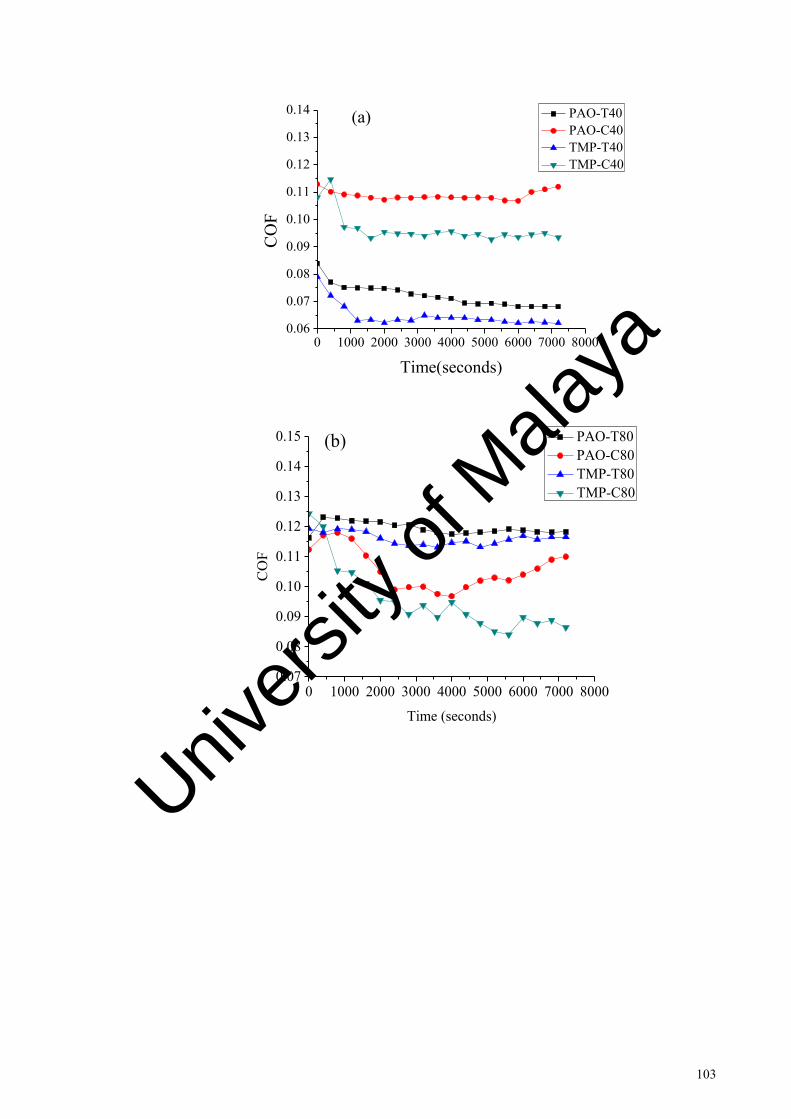
103
0 1000 2000 3000 4000 5000 6000 7000 80000.06
0.07
0.08
0.09
0.10
0.11
0.12
0.13
0.14
CO
F
Time(seconds)
PAO-T40 PAO-C40 TMP-T40 TMP-C40
(a)
0 1000 2000 3000 4000 5000 6000 7000 80000.07
0.08
0.09
0.10
0.11
0.12
0.13
0.14
0.15 (b)
CO
F
Time (seconds)
PAO-T80 PAO-C80 TMP-T80 TMP-C80
Univers
ity of
Mala
ya

104
0 1000 2000 3000 4000 5000 6000 7000 80000.080.090.100.110.120.130.140.150.160.170.18
CO
F
Time (seconds)
PAO-T125 PAO-C125 TMP-T125 TMP-C125
(c)
Figure 4.10 continued: Change in coefficient of friction of amorphous
hydrogenated carbon coated samples with time (a) temperature 40º C, (b)
temperature 80º C and (c) temperature 125º C
Samples PAO-T40 and TMP-T40 showed lower coefficient of friction compared to
samples PAO-C40 and TMP-C40 throughout the friction test (Figure 4.12 a). Textures
helped in lowering the coefficient of friction for lubricants tested by acting as lubricant
reservoirs and wear particle traps. In textured and un-textured cases, palm based TMP
showed lower coefficient of friction throughout the test compared to PAO lubricant.
Samples PAO-T40 and TMP-T40 showed lower wear coefficient compared to un-
textured samples. Sample PAO-C40 showed higher wear coefficient compared to sample
TMP-C40. Better lubricity of palm based TMP lubricant has been observed previously
by Zulkifli et al. (Zulkifli et al., 2014) in steel-steel contact.
Figure 4.12 b shows that coefficient of friction curve of sample PAO-T80 was lower
than PAO-C80 at the start of the test. After 1,000 seconds, the coefficient of friction
reduced for sample PAO-C80, whereas sample PAO-T80 remained stable till the end of
the test; however, sample PAO-C80 showed an increase in coefficient of friction after
4,600 s. Sample TMP-C80 showed similar unstable behavior as sample PAO-C80.
Univers
ity of
Mala
ya
105
Sample TMP-T80 showed lower coefficient of friction nearly throughout the test
compared to sample PAO-T80. Similar to sample PAO-T80, sample TMP-T80 also
showed stable coefficient of friction throughout the test. Textured samples (PAO-T80 and
TMP-T80) showed lower wear coefficient compared to un-textured samples (PAO-C80
and TMP-C80). Samples TMP-C80 and TMP-T80 showed lower wear coefficient than
samples PAO-C80 and PAO-T80, respectively (Figure 4.13).
Coefficient of friction in the case of samples PAO-C125 and PAO-T125, showed a
sudden increase in the start. As the test progressed, coefficient of friction reduced for
sample PAO-C125 until 5,400 s; afterwards, it increased and did not stabilize till the end
of the friction test (Figure 4.12 c). Sample TMP-C125 showed sudden decrease in
coefficient of friction at 2000 s and then showed sudden increase at 5000 s. After the
initial instability, coefficient of friction in the case of sample PAO-T125, steadily
increased to 0.132 at the end of the test (Figure 4.12 c). Sample TMP-T125 showed higher
coefficient of friction compared to sample PAO-T125, the coefficient of friction curve of
the sample TMP-T125 was nearly stable throughout the test. Wear coefficient behavior
at 125 °C with respect to textured and un-textured samples was nearly similar to 40 and
80 °C (Figure 4.13). Textured samples showed lower wear coefficient compared to un-
textured samples. Wear coefficient of samples tested in palm based TMP lubricant was
higher compared to PAO lubricant. This behavior was different to tests conducted at
temperature 40 °C and 80 °C, where palm based TMP showed lower wear coefficient
irrespective of whether they are textured or un-textured.
Palm based TMP ester performance reduces at temperature higher than 80 °C. At
higher temperature the COF and wear increases. This is related to the lower stability of
tribo-film formed by fatty acids at higher temperature (Zulkifli et al. 2013).
Univers
ity of
Mala
ya

106
PAO-T40
PAO-C40
TMP-T40
TMP-C40
PAO-T80
PAO-C80
TMP-T80
TMP-C80
PAO-T125
PAO-C125
TMP-T125
TMP-C125
0
20
40
60
80
100
120
Wea
r Coe
ffic
ient
(10
-8 m
m3 /N
m)
a-C:H Coating Steel Ball
Figure 4.11: Wear coefficient of amorphous hydrogenated carbon coated
textured/un-textured samples after tribological testing at various temperatures
The lower coefficient of friction in the case of palm based TMP lubricant at 40 ºC and
80 ºC in textured and un-textured case can be due to its high polarity (Gellman & Spencer,
2002). Lubricity is a surface energy phenomenon, as palm based TMP has higher polarity
it is easily attracted towards the metal surface (Zulkifli et al., 2013). The higher polarity
forms a higher affinity for metal from one end of the molecule and allows a non-polar
hydrocarbon to extend out and provide a barrier between the tribo-pair (Canter, 2009;
Zulkifli et al., 2014). In addition, palm oil has longer carbon chain length (18-20), due to
which the formed film behaves as a crystalline solid and reduces the coefficient of friction
(Bhushan, 2013). The higher coefficient of friction and wear in case of palm based TMP
lubricant compared to PAO lubricant at 125º C can be due to the unstable film formation
of palm based TMP lubricant at higher temperatures. This has been observed previously.
Univers
ity of
Mala
ya

107
At higher temperature's film formed by fatty acid chains are unstable, thus increasing
friction and wear (Rafiq et al., 2012) (Zulkifli et al., 2014).
The reason for the decrease in coefficient of friction of un-textured amorphous
hydrogenated carbon coating at 40, 80 and 125 °C can be due to graphitization
transformation. The reduction in coefficient of friction due to graphitization has been
noticed previously (López et al., 2003). Highly disordered structure of DLC film steadily
transforms to ordered structure at the elevated temperatures. Films form an unsteady
phase during deposition, when thermal energy is introduced, structure of these films is
re-oriented (Erdemir & Fenske, 1996; Wu & Hon, 1999). At high temperature, diffusion
of unbounded hydrogen atoms produces a spongy structure for the film of hydrogenated
DLC. These structural and chemical changes also cause modifications in friction and wear
behavior. After exposing at high temperature, final product may become highly porous
and a soft graphitic thin layer may appear, which wears out rapidly. At elevated
temperature, endurance limit for non-hydrogenated films is higher than hydrogenated
films.
Due to graphitization, the coating layer becomes soft and the load-bearing capacity
reduces and wear increases (Kalin et al., 2010). This could be the reason for the higher
wear rate in the case of un-textured amorphous hydrogenated carbon at 40 °C, 80 °C and
125 °C, as can be seen in Figure 4.13. Wear coefficient results nearly followed the
coefficient of friction trend in the textured amorphous hydrogenated carbon case,
whereas, in the case of un-textured a-C:H, It was opposite to the coefficient of friction
trend. This opposite trend of un-textured amorphous hydrogenated carbon can be
explained by the fact that graphitization helps in reduction of a coefficient of friction;
However, the adverse effect of graphitization transformation is increased wear rate. This
will be further discussed in section 4.3.2. The increase in the coefficient of friction for
Univers
ity of
Mala
ya

108
un-textured amorphous hydrogenated carbon in palm based TMP and PAO lubricant at
the later part of friction testing may be due to coating delamination. This will be further
discussed in section 4.3.3. The friction and wear performance of amorphous
hydrogenated carbon coating deteriorates with the increase in temperature (Bremond et
al., 2003). It was observed in a previous study that the tribological performance of
amorphous hydrogenated carbon coating starts to change around 100 ºC (Vanhulsel et al.,
1998). However, the textured amorphous hydrogenated carbon showed higher wear
resistance compared to the un-textured amorphous hydrogenated carbon even at
temperature above 100 °C.
4.3.2 Wear track characterization of amorphous hydrogenated carbon coating
4.3.2.1 Raman analysis
Raman spectroscopy was used to investigate the graphitization behavior of amorphous
hydrogenated carbon coating. Three Raman measurements were taken to present a
statistical representation of results so that the inaccuracies resulting from peak fitting
could be minimized.
The atomic structure of amorphous hydrogenated carbon coating consists of sp3, sp2
and monovalent hydrogen bonds (Neville et al., 2007). The release of hydrogen from the
amorphous hydrogenated carbon coating matrix triggers the transformation from a sp3
structure to a graphite-like sp2 structure. Graphitization can occur because of higher
contact temperature and/or high contact stress (Haque et al., 2009). Haque et al. (Haque
et al., 2009) suggested that due to the micron-sized wear particles produced during the
sliding test, the contact pressure reduces the graphitization temperature to as low as 95
ºC. These particles can be generated from counter ball wear (Haque et al., 2009). Ding et
al. (Ding et al., 2010) proposed that, due to fatigue wear mechanisms, DLC wear debris
Univers
ity of
Mala
ya

109
can be created at the contact, which can lower the graphitization temperature. This can
explain the graphitization transformation at 40 ºC in our study.
Figure 4.14 and Figure 4.15 shows the Raman spectra’s for various textured and un-
textured samples tested under PAO and palm based TMP lubrication. Raman spectra were
fitted into D and G peaks for quantitative analysis. The G peak indicates the stretching
vibration of sp2 carbon in C = C chains and aromatic rings, whereas the D peak indicates
the breathing mode of sp2 carbon in the aromatic rings (Casiraghi et al., 2005). The shift
in the G peak and increase in the ID/IG ratio indicate an increase in the sp2 fraction
(graphite) in the DLC film (Casiraghi et al., 2005; Ferrari & Robertson, 2000). The G
peak and ID/IG ratio of as deposited amorphous hydrogenated carbon coating was 1533.77
cm-1 and 1.17 respectively. The G peak, in the case of the samples PAO-T40 and TMP-
T40 (Figures 4.14 and 4.15) shifted slightly from the as deposited coating. Whereas PAO-
C40 and TMP-C40 (Figures 4.14 and 4.15) showed the higher increase in the G peak
shifts from the as deposited value. The ID/IG ratio increase was also low for samples PAO-
T40 and TMP-T40 (Figures 4.14 and 4.15) than PAO-C40 and TMP-C40 (Figures 4.14
and 4.15). This indicates that, at lower temperatures, textured amorphous hydrogenated
carbon showed slight graphitization transformation in the presence of PAO and palm
based TMP lubricants compared to un-textured amorphous hydrogenated carbon. This
result confirms that the lower coefficient of friction of PAO-T40 and TMP-T40, was not
because of graphitization, rather, the mechanism of textures (fluid/ debris reservoir) was
responsible for this. In the case of PAO-C40 (Figure 4.14), G peak shifted from 1533.77
cm-1 to 1555.27 cm-1 and ID/IG ratio increased from 1.17 to 1.51. This shows that at 40 ºC
higher graphitization transformation occurred for un-textured amorphous hydrogenated
carbon. In the case of TMP-C40 change in the G peak position from 1533.77 cm-1 to
1548.39 cm-1 and ID/IG ratio changed from 1.17 to 1.31 has been observed. Due to
graphitization, the coating becomes soft and thus wears coefficient increases. The lower
Univers
ity of
Mala
ya

110
wear coefficient for the case of PAO-T40 and TMP-T40 can be related to reduction in
graphitization. In addition, TMP-C40 showed reduced wear coefficient compared to
PAO-C40. This can also be related to the better lubricity of palm based TMP at the low
temperatures. The dependence of graphitization is on sliding distance, load, and contact
type. PAO and palm based TMP both showed graphitization. No relationship was found,
which indicate that palm based TMP affects the graphitization behavior.
1000 1200 1400 1600 1800 2000
Rama
n Inte
nsity
(au)
Raman Shift (cm -1)
D-Peak G-Peak Cumulative Fit Peak
As deposited a-C:HD Peak = 1351.08G Peak = 1533.77ID/IG = 1.17
Before test
Univers
ity of
Mala
ya

111
1000 1200 1400 1600 1800 2000
D-Peak G-Peak Cumulative Fit Peak
PAO-C40D Peak = 1372.02 G Peak = 1555.27ID/IG = 1.51
After Test
Ram
an I
nte
nsi
ty (
au)
Raman Shift (cm-1)
1000 1200 1400 1600 1800 2000
D-Peak G-Peak Cumulative Fit Peak
PAO-T40D Peak = 1354.30 G Peak = 1536.37ID/IG = 1.19
After Test
Ram
an In
tensit
y (a
u)
Raman Shift (cm-1)
Univers
ity of
Mala
ya

112
1000 1200 1400 1600 1800 2000
D-Peak G-Peak Cumulative Fit Peak
PAO-C125D Peak =1378.79 G Peak = 1552.12ID/IG = 2.01After test
Ram
an In
tensit
y (au
)
Raman Shift (cm -1)
800 1000 1200 1400 1600 1800 2000
D-Peak G-Peak Cumulative Fit Peak
PAO-T125D Peak = 1358.08G Peak = 1537.77ID/IG = 1.18After test
Ram
an I
nten
sity
(au
)
Raman Shift (cm -1)
Figure 4.12 continued: Raman spectra of various textured/un-textured
amorphous hydrogenated carbon coating at various temperatures in the
presence of PAO lubricant
Univers
ity of
Mala
ya

113
1000 1200 1400 1600 1800 2000
Rama
n Inte
nsity
(au)
Raman Shift (cm -1)
D-Peak G-Peak Cumulative Fit Peak
As deposited a-C:HD Peak = 1351.08G Peak = 1533.77ID/IG = 1.17
Before test
1000 1200 1400 1600 1800 2000
D-Peak G-Peak Cumulative Fit Peak
TMP-C40D Peak = 1360.7 G Peak = 1548.39ID/IG = 1.31
After Test
Ram
an In
tens
ity (a
u)
Raman Shift (cm-1)
Univers
ity of
Mala
ya

114
1000 1200 1400 1600 1800 2000
D-Peak G-Peak Cumulative Fit Peak
Raman Shift (cm-1)
Ram
an In
tensit
y (a
u)
TMP-T40D Peak = 1353.87G Peak = 1536.80ID/IG = 1.18
After Test
1000 1200 1400 1600 1800 2000
D-Peak G-Peak Cumulative Fit Peak
TMP-C125D Peak = 1376.03G Peak = 1559.74ID/IG = 1.57
After Test
Ram
an In
tens
ity (a
u)
Raman Shift (cm-1)
Univers
ity of
Mala
ya

115
1000 1200 1400 1600 1800 2000
D-Peak G-Peak Cumulative Fit Peak
TMP-T125D Peak = 1355.11 G Peak = 1535ID/IG = 1.20
After TestRa
man
Inte
nsity
(au)
Raman Shift (cm-1)
Figure 4.13 continued: Raman spectra of various textured/un-textured
amorphous hydrogenated carbon coating at various temperatures in the
presence of palm based TMP lubricant
In the case of samples PAO-C125 and TMP-C125, the G peaks shifted from 1533.77
cm-1 to 1552.12 cm-1 and 1559.74 cm-1, respectively. In addition, the ID/IG ratio for
samples PAO-C125 and TMP-C125 increased from 1.17 to 2.01 and 1.57, respectively
(Figures 4.14 and 4.15). This shows that, as the temperature increased to 125 ºC
graphitization transformation increased. In the case of PAO-T125 and TMP-T125, the G
peaks shifted from 1533.77 cm-1 to 1537.77 cm-1 and 1535 cm-1, respectively. Whereas,
the ID/IG ratio samples PAO-T125 and TMP-T125 increased from 1.17 to 1.18 and 1.20,
respectively. These results indicate that even at higher temperatures a lower
graphitization transformation can be observed from the case of textured coating
irrespective of lubricant used. The Raman analysis shows that graphitization
Univers
ity of
Mala
ya

116
transformation of textured amorphous hydrogenated carbon was too low compared to un-
textured amorphous hydrogenated carbon.
The lower graphitization in the case of textured amorphous hydrogenated carbon at
higher temperatures may be due to multiple factors, including the wear debris trapping
ability and the lubricant retention and providing the ability of micro dimples. Textures
can remove the wear debris from the contacting surface, which can reduce the increase in
contact pressure due to the wear particles between the tribo-pairs. Additionally, by
keeping the lubricant at the interface, they can lower the rise in temperature due to
friction-induced heating. In the case of textured mechanical seals, Xiao et al. (Xiao &
Khonsari, 2012) observed that micro dimples could lower the interface temperature by
keeping lubricant at the interface.
4.3.2.2 SEM/EDX and AFM analysis
Figure 4.16 shows the SEM images of wear tracks; the white arrow indicates the
sliding direction. EDX quantitative analyses of the SEM images, are shown in Table 4.3.
Polishing wear was observed from the case of samples PAO-T40 and TMP-T40 (Figures
4.16 a and 4.16 c). The polishing wear process is the one in which micro grooves are not
seen before the complete removal or delamination of coating. The brighter areas present
on the wear tracks are due to the thinning of coating and exposure of silver-colored CrN.
Samples PAO-C40 and TMP-C40 showed coating spallation and partial delamination on
the wear track (Figures 4.16 b and 4.16 d). Sample PAO-T125 showed coating spallation
on the wear track (Figure 4.16 e), whereas a sample TMP-T125 (Figure 4.16 g) showed
spallation and delamination at few spots. Samples PAO-C125 and TMP-C125 (Figures
4.16 f and 4.16 h) exhibited scratch marks and extensive coating delamination. Samples
PAO-C125 and TMP-C125 showed a higher increase of Fe and decrease of C compared
to as-deposited amorphous hydrogenated carbon coating (Table 4.3), which indicates that
Univers
ity of
Mala
ya

117
coating peeled off during the sliding test. Sample PAO-T125 showed fewer increases in
Fe and decrease in C compared to sample PAO-C125 (Table 4.3). The scratches present
on samples PAO-C125 indicated the abrasive wearing of coating by the wear particles
present at the interface (Figures 4.16 f). The absence of the abrasive wear marks on
samples PAO-T40, TMP-T40, PAO-T125 and TMP-T125 are due to the textures (Figures
4.16 a, 4.16 c, 4.16 e and 4.16 g), which trap these wear particles and causes lower
abrasive wearing.
Univers
ity of
Mala
ya

118
Univers
ity of
Mala
ya

119
Univers
ity of
Mala
ya

120
Univers
ity of
Mala
ya

121
Figure 4.14 continued: SEM images of wear track after friction testing (a)
PAO-T40, (b) PAO-C40, (c) TMP-T40, (d) TMP-C40, (e) PAO-T125, (f) PAO-
C125, (g) TMP-T125 and (h) TMP-C125
Table 4.3: EDX analysis of un-textured/textured amorphous hydrogenated
carbon coated samples at various temperatures
Specimen Elements (Atomic %)
C O Cr Fe Si Mn
a-C:H-as deposited 97.01 0.45 2.20 0.34 - -
PAO-T40 93.48 0.75 4.92 0.85 - -
PAO-C40 84.38 1.12 8.92 5.58 - -
TMP-T40 94.12 2.45 2.91 0.52 - -
TMP-C40 89.99 2.77 5.67 1.57 - -
PAO-T125 85.18 0.84 8.44 5.54 - -
PAO-C125 36.84 1.40 18.32 42.89 0.55 -
TMP-T125 83.01 2.45 9.22 5.32 - -
TMP-C125 34.23 3.45 21.22 41.10 - -
Univers
ity of
Mala
ya

122
To further analyze the wear track, AFM was used. Figure 4.17 shows the AFM images
of samples at various temperatures. Un-textured coated samples PAO-C40, PAO-C125,
TMP-C40 and TMP-C125 showed sharp grooves that were created by the wear particles
present in the interface (Figure 4.17 b, 4.17 d, 4.17 f and 4.17 h). These particles scratch
the surface during sliding. Textured coated samples PAO-T40, PAO-T125, TMP-T40 and
TMP-T125 did not show sharp grooves on the wear tracks (Figure 4.17). As it has been
discussed in the previous paragraph, the wear particle capturing ability of textures helps
in reducing the formation of sharp grooves on the track. Figure 4.18 shows the average
roughness (Ra) of the samples. Sample TMP-T40 showed the lowest and TMP-C125
showed the highest average roughness. The general trend followed by all the samples is
that average surface roughness increases with the increase in temperature. However, this
increase is lower in the case of textured samples. Wear particle capturing and lubricant
providing ability helps in lowering the surface roughness.
Univers
ity of
Mala
ya
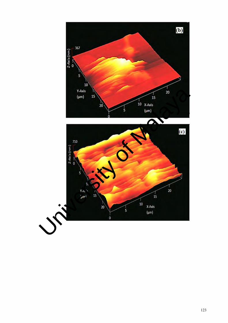
123
Univers
ity of
Mala
ya

124
Univers
ity of
Mala
ya
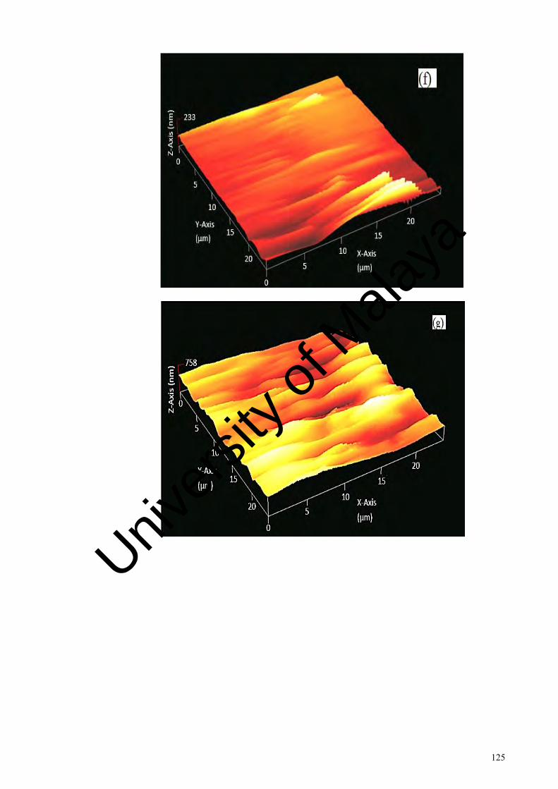
125
Univers
ity of
Mala
ya
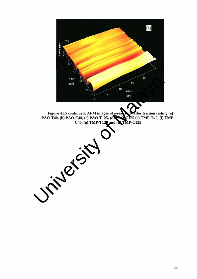
126
Figure 4.15 continued: AFM images of wear track after friction testing (a)
PAO-T40, (b) PAO-C40, (c) PAO-T125, (d) PAO-C125 (e) TMP-T40, (f) TMP-
C40, (g) TMP-T125 and (h) TMP-C125
Univers
ity of
Mala
ya

127
PAO-T40
PAO-C40
TMP-T40
TMP-C40
PAO-T125
PAO-C125
TMP-T125
TMP-C125
0
20
40
60
80
100
Surfa
ce R
ough
ness
(nm
)
Figure 4.16: Average surface roughness at the wear track after friction testing
Figure 4.19 shows the wear rate of the counter ball, in the case of textured and un-
textured amorphous hydrogenated carbon samples. The steel ball, which rubbed against
sample PAO-T125 (Figure 4.19 a), showed smoother surface, whereas the ball which
rubbed against PAO-C125 showed slight grooves (Figure 4.19 b). The ball that rubbed
against sample TMP-T125 (Figure 4.19 c) and TMP-C125 (Figure 4.19 d) showed similar
behavior to PAO-T125 and PAO-C125. The reduction in wear of the PAO-T125 and
TMP-T125 counter ball can be caused by the mechanism of dimples. In the case of
textured amorphous hydrogenated carbon, the counter ball wear rate increases with the
increase in temperature (Figure 4.13). At 125 ºC, the un-textured amorphous
hydrogenated carbon showed lower wear rate than textured amorphous hydrogenated
carbon. The reduction in wear rate in the case of un-textured amorphous hydrogenated
carbon can be attributed to the fact that, due to graphitization, a graphitic transfer film
forms on the counter surface, which provides an easy slip between the contacting surfaces
(C. Donnet, 1998). In the case of textured a-C:H, the increase in wear rate of the counter
ball with regard to temperature can be due to the lower graphitization with temperature,
Univers
ity of
Mala
ya

128
which reduces the formation of graphitic transfer film. This has been confirmed with
raman spectroscopy in section 4.3.2.1.
Smoother
Surface
Univers
ity of
Mala
ya

129
Figure 4.17 continued: SEM images of steel balls which rub against (a) PAO-
T125, (b) PAO-C125, (c) TMP-T125 and (d) TMP-C125
Univers
ity of
Mala
ya

130
4.4 Effect of surface texture on tribological performance of tetrahedral
amorphous carbon coating at various temperatures
4.4.1 Friction and wear behavior
Figure 4.20 shows the coefficient of friction variation with time for textured
tetrahedral amorphous carbon coated and un-textured tetrahedral amorphous carbon
coated samples under PAO and palm based TMP lubrication.
Samples ta-C.PAO-T40 and ta-C.TMP-T40 showed stable and lower coefficient of
friction compared to samples ta-C.PAO-C40 and ta-C.TMP-C40 throughout the friction
test (Figure 4.20 a). Lower coefficient of friction of textured tetrahedral amorphous
carbon coating can be related to the ability of micro textures to provide lubricant at the
interface and capture wear particles. Dumitru et al. observed stable coefficient of friction
with textured DLC compared to un-textured DLC (Dumitru et al., 2003). They concluded
that textures trap hard wear debris which causes abrasive wear and as a result make
friction unstable (Dumitru et al., 2003). In textured and un-textured cases, palm based
TMP showed lower coefficient of friction throughout the test compared to PAO at 40 ºC.
As previously mentioned, in case of amorphous hydrogenated carbon coating that the
lower coefficient of friction in TMP lubricant at 40 ºC in textured and un-textured case
can be due to its high polarity (Gellman & Spencer, 2002). Due to this, it is easily attracted
to steel surface. The higher polarity forms a higher affinity for metal at one end of the
molecule and allows a non-polar hydrocarbon to extend out and provide a barrier between
the tribo-pair (Canter, 2009; Zulkifli et al., 2014). In addition, palm oil has longer carbon
chain length (18-20), due to which the formed film behaves as a crystalline solid and
reduces coefficient of friction (Bhushan, 2013). After 800 s, ta-C.PAO-C40 showed
stable coefficient of friction until 2800 s, ta-C.TMP-C40 showed nearly stable coefficient
of friction until 4800 s. Both the samples nearly stabilized around 5600 s and remained
stable until the end of test. Figure 4.21 shows the wear coefficient for various samples
Univers
ity of
Mala
ya

131
tested with PAO and palm based TMP ester. Sample ta-C.TMP-C40 showed lower wear
coefficient than sample ta-C.PAO-C40 (Figure 4.21). Textured sample ta-C.TMP-T40
showed lower wear coefficient than un-textured sample ta-C.PAO-T40 (Figure 4.21). In
textured and un-textured cases, palm based TMP lubricant showed lower wear coefficient
compared to PAO lubricant at 40 ºC. Better lubricity of palm based TMP lubricant was
also observed in the case of amorphous hydrogenated carbon coating in section 4.3.1.
At 80 ºC temperature, textured samples ta-C.PAO-T80 and ta-C.TMP-T80 exhibited
stable coefficient of friction. PAO lubricated sample ta-C.PAO-T80 showed higher
coefficient of friction compared to palm based TMP lubricated sample ta-C.TMP-T80.
Coefficient of friction of un-textured samples (ta-C.TMP-C80 and ta-C.PAO-C80)
exhibited unstable behavior. The lower coefficient of friction of un-textured tetrahedral
amorphous carbon coating at 80 ºC can be due to graphitization phenomenon. The
graphitization phenomenon will be discussed in detail in section 4.4.2.1. Figure 4.21
shows that textured samples (ta-C.PAO-T80 and ta-C.TMP-T80) showed lower wear
coefficient compared to un-textured samples (ta-C.PAO-C80 and ta-C.TMP-C80).
Amorphous hydrogenated carbon coating also showed similar behavior at 80 ºC in section
4.3.1.
Univers
ity of
Mala
ya

132
0 1000 2000 3000 4000 5000 6000 7000 80000.0500.0550.0600.0650.0700.0750.0800.0850.0900.0950.100
CO
F
Sliding Time (seconds)
ta-C.PAO-C40 ta-C.PAO-T40 ta-C.TMP-C40 ta-C.TMP-T40
(a)
0 1000 2000 3000 4000 5000 6000 7000 80000.0500.0550.0600.0650.0700.0750.0800.0850.0900.0950.100
CO
F
Sliding Time (seconds)
ta-C.PAO-C80 ta-C.PAO-T80 ta-C.TMP-C80 ta-C.TMP-T80
(b)
Univers
ity of
Mala
ya
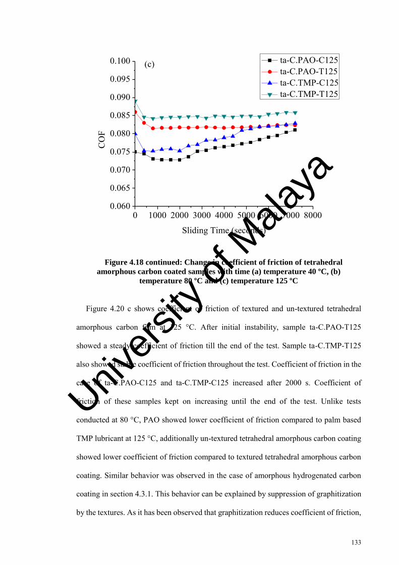
133
0 1000 2000 3000 4000 5000 6000 7000 80000.060
0.065
0.070
0.075
0.080
0.085
0.090
0.095
0.100
CO
F
Sliding Time (seconds)
ta-C.PAO-C125 ta-C.PAO-T125 ta-C.TMP-C125 ta-C.TMP-T125
(c)
Figure 4.18 continued: Change in coefficient of friction of tetrahedral
amorphous carbon coated samples with time (a) temperature 40 ºC, (b)
temperature 80 ºC and (c) temperature 125 ºC
Figure 4.20 c shows coefficient of friction of textured and un-textured tetrahedral
amorphous carbon film at 125 °C. After initial instability, sample ta-C.PAO-T125
showed a steady coefficient of friction till the end of the test. Sample ta-C.TMP-T125
also showed stable coefficient of friction throughout the test. Coefficient of friction in the
case of ta-C.PAO-C125 and ta-C.TMP-C125 increased after 2000 s. Coefficient of
friction of these samples kept on increasing until the end of the test. Unlike tests
conducted at 80 °C, PAO showed lower coefficient of friction compared to palm based
TMP lubricant at 125 °C, additionally un-textured tetrahedral amorphous carbon coating
showed lower coefficient of friction compared to textured tetrahedral amorphous carbon
coating. Similar behavior was observed in the case of amorphous hydrogenated carbon
coating in section 4.3.1. This behavior can be explained by suppression of graphitization
by the textures. As it has been observed that graphitization reduces coefficient of friction,
Univers
ity of
Mala
ya

134
therefore un-textured tetrahedral amorphous carbon coating showed lower coefficient of
friction at 125 °C. The reduction in graphitization transformation can explain the lower
increase in the wear rate of textured tetrahedral amorphous carbon coating compared to
un-textured tetrahedral amorphous carbon coating at various temperatures tested in both
lubricants. Wear coefficient results at 125 °C with respect to textured and un-textured
samples was similar to 40 and 80 °C (Figure 4.21). Samples ta-C.PAO-T125 and ta-
C.TMP-T125 showed lower wear coefficient than samples ta-C.PAO-C125 and ta-
C.TMP-C125. Wear coefficient of samples tested in palm based TMP lubricant was
higher compared to PAO lubricant at 125 °C. This behavior was dissimilar to tests
conducted at temperature 40 and 80 °C where palm based TMP showed lower wear
irrespective of whether they are textured or un-textured. The higher coefficient of friction
and wear in case of PAO compared to palm based TMP at 125 ºC can be due to the
unstable film formation of palm based TMP at higher temperatures. At higher
temperatures film formed by fatty acid chains are unstable, thus increasing friction and
wear (Chiong et al., 2012)
Univers
ity of
Mala
ya

135
ta-C.PAO-C
40
ta-C.PAO-T40
ta-C.TMP-C
40
ta-C.TMP-T40
ta-C.PAO-C
80
ta-C.PAO-T80
ta-C.TMP-C
80
ta-C.TMP-T80
ta-C.PAO-C
125
ta-C.PAO-T125
ta-C.TMP-C
125
ta-C.TMP-T125
0
10
20
30
40
50
60
70
Wea
r Coe
ffici
ent (
10 -8
mm
3 /Nm
) ta-C Coating Steel Ball
Figure 4.19: Wear coefficient of tetrahedral amorphous carbon coated
textured/un-textured samples after tribological testing at various temperatures
Due to graphitization, the coating layer becomes soft and the load bearing capacity
reduces and wear increases (Kalin et al., 2010). This could be the reason for the higher
wear rate in the case of un-textured tetrahedral amorphous carbon coating at 40 °C, 80 °C
and 125 °C, as can be seen in Figure 4.21. With the increase in temperature, graphitization
increases and thus wear coefficient increases for tetrahedral amorphous carbon coating
(Al Mahmud et al., 2014).
4.4.2 Wear track characterization of tetrahedral amorphous carbon coating
4.4.2.1 Raman analysis
In order to investigate the behavior of graphitization for tetrahedral amorphous carbon
coating Raman spectroscopy was used. Tetrahedral amorphous carbon coating is a
metastable form of amorphous carbon and friction induced graphitization can occur
Univers
ity of
Mala
ya
136
(Donnet & Erdemir, 2007). In order to avoid inaccuracies, three Raman spectra was
collected for each sample to avoid inaccuracies from peak fitting.
Figures 4.22 and 4.23 shows the spectra’s for samples tested in PAO and palm based
TMP lubricants respectively. After coating deposition, the G peak position was at 1558.18
cm-1 and the ID/IG ratio was 1.12. After tribological testing, tetrahedral amorphous carbon
coated samples ta-C.PAO-C40 and ta-C.TMP-C40 showed G peak at 1566.39 cm-1 and
1566.32 cm-1 respectively. The ID/IG ratio of 1.42 and 1.5 was shown by tetrahedral
amorphous carbon coated samples ta-C.PAO-C40 and ta-C.TMP-C40 respectively.
Textured tetrahedral amorphous carbon coated samples ta-C.PAO-T40 and ta-C.TMP-
T40 showed G peak at 1560 cm-1 and 1559.55 cm-1 respectively. The ID/IG ratio for
textured tetrahedral amorphous carbon coated samples ta-C.PAO-T40 and ta-C.TMP-T40
was 1.14 and 1.15, respectively (Figures 4.22 and 4.23). The shift in the G peak and
increase in the ID/IG ratio indicate an increase in the sp2 fraction (graphite) in the DLC
film (Casiraghi et al., 2005; Ferrari & Robertson, 2000). The higher increase in G peak
and ID/IG ratio of un-textured coated samples compared to textured samples indicates that
at 40 ºC, un-textured tetrahedral amorphous carbon coated samples ta-C.PAO-C40 and
ta-C.TMP-C40 showed higher graphitic transformation. As was discussed in section
4.3.2.1, graphitic transformation reduces coefficient of friction, whereas it increases wear
coefficient. However, textured tetrahedral amorphous carbon coated samples ta-C.PAO-
T40 and ta-C.TMP-T40 showed less coefficient of friction and wear coefficient than un-
textured samples even though textured tetrahedral amorphous carbon coated samples
showed lower graphitic transformation at 40 ºC. This indicates that lower coefficient of
friction and wear coefficient of textured tetrahedral amorphous carbon coated samples
can be because of textures behaving as lubricant/wear particle reservoirs. Similar results
were observed in the case of amorphous hydrogenated carbon coated samples at 40 ºC in
section 4.3.2.1.
Univers
ity of
Mala
ya

137
1000 1200 1400 1600 1800 2000
D-Peak G-Peak Cumulative Fit Peak
As-deposited ta-CD Peak = 1347.11 G Peak = 1558.18ID/IG = 1.12
Ram
an In
tens
ity (a
u)
Raman Shift (cm-1)
1000 1200 1400 1600 1800 2000
D-Peak G-Peak Cumulative Fit Peak
ta-C.PAO-C40D Peak = 1378.70 G Peak = 1566.39ID/IG = 1.42
Ram
an In
tens
ity (a
u)
Raman Shift (cm-1)
Univers
ity of
Mala
ya

138
1000 1200 1400 1600 1800 2000
D-Peak G-Peak Cumulative Fit Peak
ta-C.PAO-T40D Peak = 1344.22 G Peak = 1560ID/IG = 1.14
Ram
an In
tens
ity (a
u)
Raman Shift (cm-1)
1000 1200 1400 1600 1800 2000
D-Peak G-Peak Cumulative Fit Peak
ta-C.PAO-C125D Peak = 1383.53 G Peak = 1566.21ID/IG = 1.55
Ram
an In
tens
ity (a
u)
Raman Shift (cm-1) Univers
ity of
Mala
ya
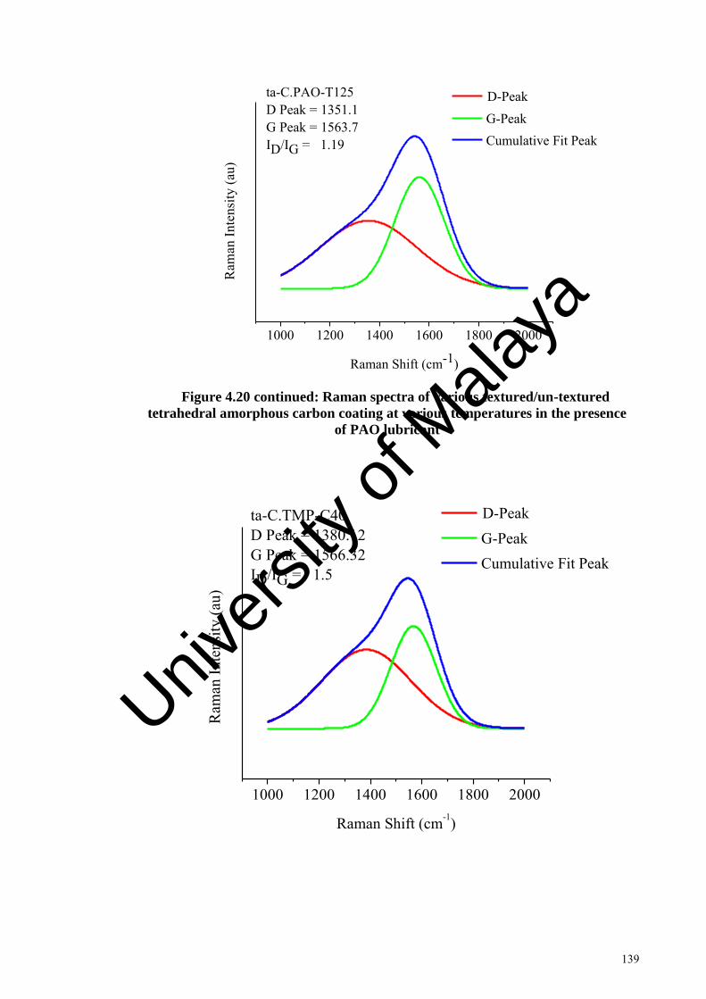
139
1000 1200 1400 1600 1800 2000
D-Peak G-Peak Cumulative Fit Peak
ta-C.PAO-T125D Peak = 1351.1 G Peak = 1563.7ID/IG = 1.19
Ram
an In
tens
ity (a
u)
Raman Shift (cm-1)
Figure 4.20 continued: Raman spectra of various textured/un-textured
tetrahedral amorphous carbon coating at various temperatures in the presence
of PAO lubricant
1000 1200 1400 1600 1800 2000
D-Peak G-Peak Cumulative Fit Peak
ta-C.TMP-C40D Peak = 1380.12 G Peak = 1566.32ID/IG = 1.5
Ram
an In
tens
ity (a
u)
Raman Shift (cm-1)
Univers
ity of
Mala
ya
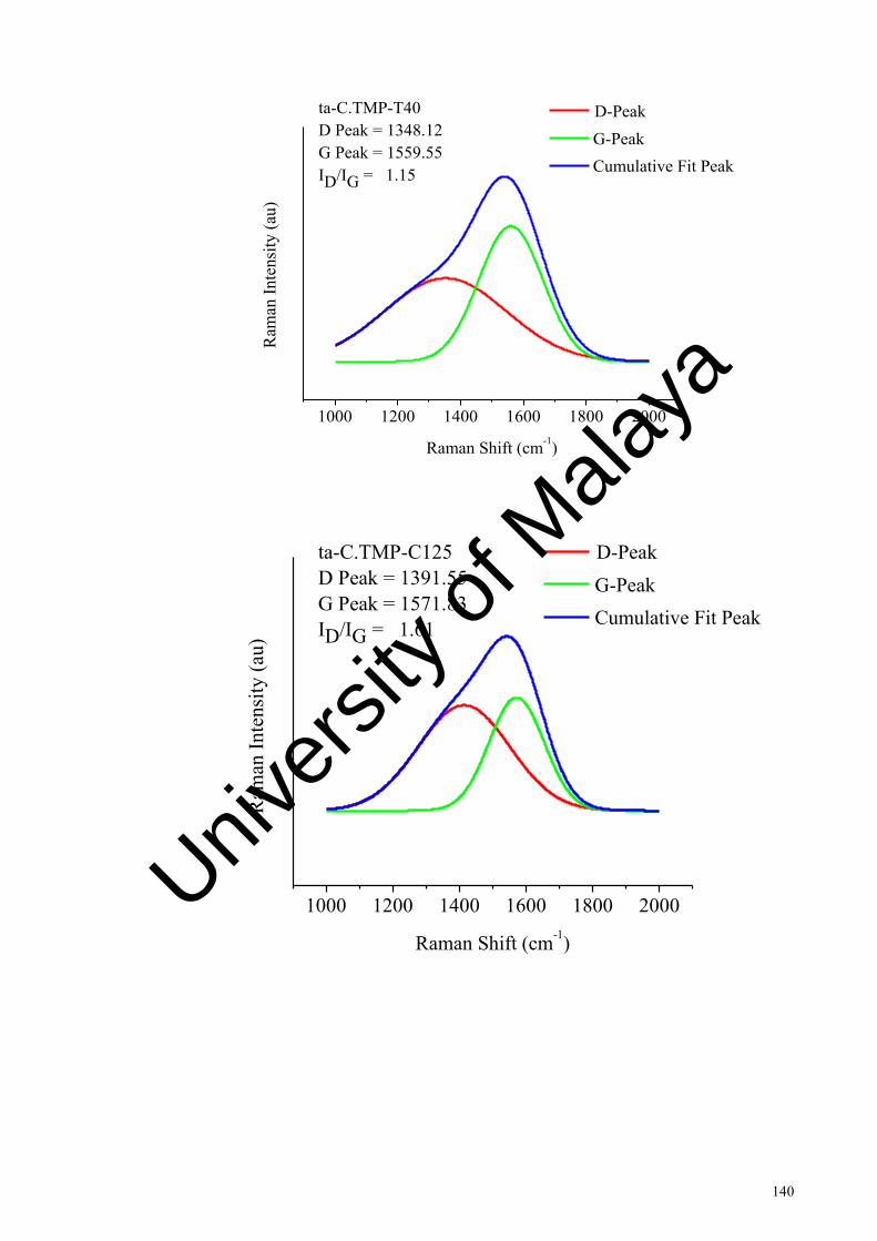
140
1000 1200 1400 1600 1800 2000
D-Peak G-Peak Cumulative Fit Peak
ta-C.TMP-T40D Peak = 1348.12 G Peak = 1559.55ID/IG = 1.15
Ram
an In
tens
ity (a
u)
Raman Shift (cm-1)
1000 1200 1400 1600 1800 2000
D-Peak G-Peak Cumulative Fit Peak
ta-C.TMP-C125D Peak = 1391.55 G Peak = 1571.83ID/IG = 1.61
Ram
an In
tens
ity (a
u)
Raman Shift (cm-1)
Univers
ity of
Mala
ya

141
1000 1200 1400 1600 1800 2000
D-Peak G-Peak Cumulative Fit Peak
ta-C.TMP-T125D Peak = 1353 G Peak = 1561ID/IG = 1.18
Ram
an In
tens
ity (a
u)
Raman Shift (cm-1)
Figure 4.21 continued: Raman spectra of various textured/un-textured
tetrahedral amorphous carbon coating at various temperatures in the presence
of palm based TMP lubricant
At a temperature of 125 ºC, textured tetrahedral amorphous carbon coated samples ta-
C.PAO-T125 and ta-C.TMP-T125 showed G peak at 1563.7 cm-1 and 1561 cm-1 and ID/IG
ratio of 1.19 and 1.18, respectively. Un-textured tetrahedral amorphous carbon coated
samples ta-C.PAO-C125 and ta-C.TMP-C125 showed G peak at 1566.21 cm-1 and
1571.83 cm-1 whereas ID/IG ratio of 1.55 and 1.61 respectively. The higher increase in G
peak position and ID/IG ratio value for un-textured tetrahedral amorphous carbon coated
samples at 125 ºC compared to as deposited tetrahedral amorphous carbon coating can be
due to the absence of textures. As textured tetrahedral amorphous carbon coated samples
showed less increase in G peak shift and ID/IG ratio value. Similar to friction and wear
results found in amorphous hydrogenated carbon coating at 125 ºC, textured tetrahedral
amorphous carbon coated samples showed higher coefficient of friction (Figures 4.20 c)
and lower wear coefficient (Figures 4.21) than un-textured tetrahedral amorphous carbon
Univers
ity of
Mala
ya

142
coated samples. These results can be explained by taking into account the mechanism of
textures to capture wear particles and prevent graphitic transformation, thus preventing
higher wear rate. As higher graphitization occurred in the case of un-textured tetrahedral
amorphous carbon coated samples at 125 ºC, lower coefficient of friction is expected
compared to textured samples.
4.4.2.2 SEM/EDX and AFM analysis
SEM images of wear tracks after friction testing are shown in Figure 4.24. Polishing
wear was observed in the case of samples ta-C.PAO-T40 and ta-C.TMP-T40 (Figure 4.24
a and 4.24 c). Samples ta-C.PAO-C40 and ta-C.TMP-C40 showed slight coating
spallation on the wear track (Figure 4.24 b and 4.24 d). Samples ta-C.PAO-T125 and ta-
C.TMP-T125 (Figures 4.24 e and 4.24 g) did not show spallation at the wear track
whereas samples ta-C.PAO-C125 and ta-C.TMP-C125 exhibited excessive coating
spallation (Figures 4.24 f and 4.24 h).
The wear behavior was confirmed by EDX analysis (Table 4.4). Samples ta-C.PAO-
C125 and ta-C.TMP-C125 showed a higher increase of Fe and decrease of C compared
to as-deposited tetrahedral amorphous carbon coating (Table 4.4), which indicates that
coating spallation occurred during the sliding test. Sample ta-C.PAO-T125 showed slight
increase in Fe and decrease in C compared to ta-C.PAO-C125 (Table 4.4).
Univers
ity of
Mala
ya

143
No spallation and delamination
Univers
ity of
Mala
ya

144
Univers
ity of
Mala
ya
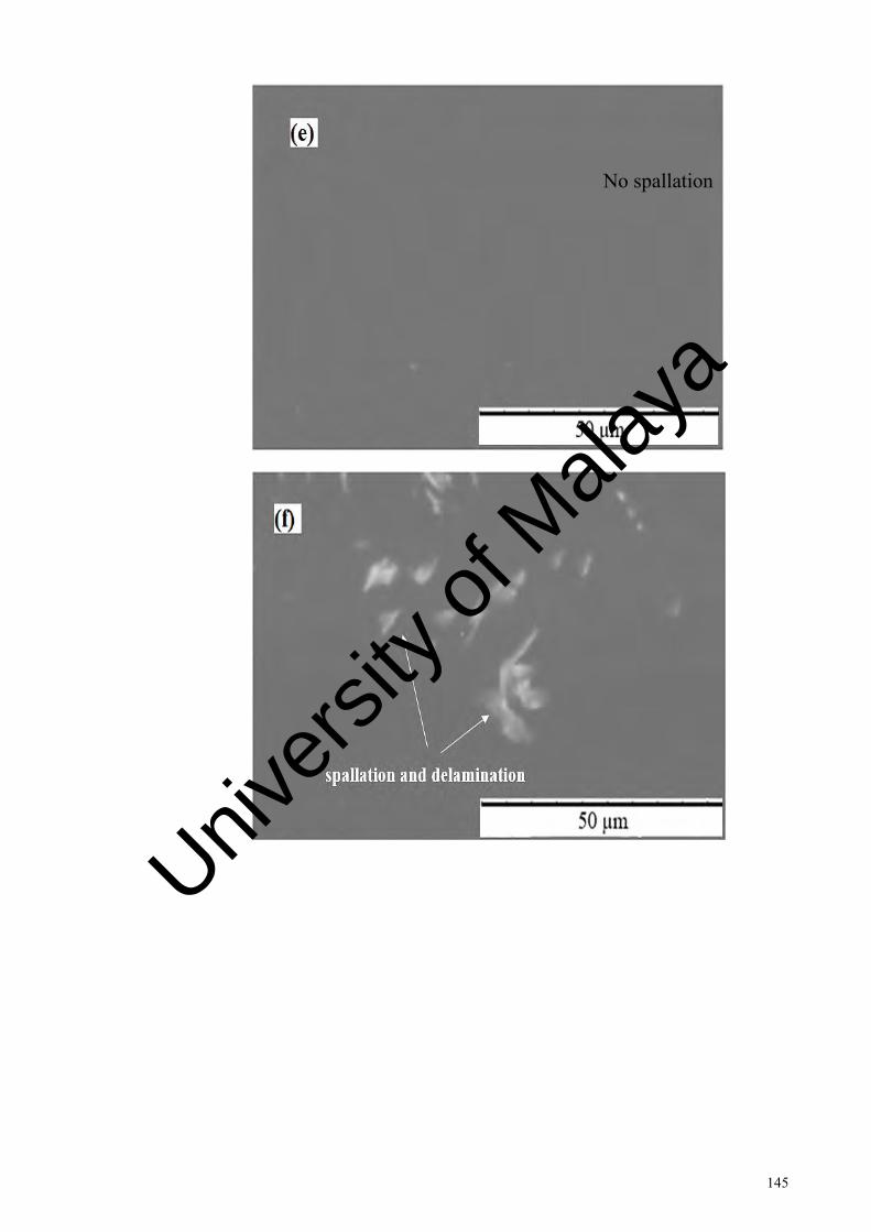
145
No spallation
Univers
ity of
Mala
ya

146
Figure 4.22 continued: SEM images of wear track after friction testing (a) ta-
C.PAO-T40, (b) ta-C.PAO-C40, (c) ta-C.TMP-T40, (d) ta-C.TMP-C40, (e) ta-
C.PAO-T125, (f) ta-C.PAO-C125, (g) ta-C.TMP-T125 and (h) ta-C.TMP-C125
To analyze the topography of the wear scar, AFM was used. Figure 4.25 shows the
AFM images of tetrahedral amorphous carbon coated samples at various temperatures.
Un-textured coated samples (ta-C.PAO-C40, ta-C.TMP-C40, ta-C.PAO-C125 and ta-
C.TMP-C125) showed sharp grooves that can be created by the wear particles present at
No spallation
Univers
ity of
Mala
ya

147
the interface (Figures 4.25 b, 4.25 d, 4.25 f and 4.25 h). During sliding micro wear
particles are formed at the interface; these particles can be from steel ball and/or hard
coating. The coating wear debris are hard enough to scratch the wear track. Textured
coated samples (ta-C.PAO-T40, ta-C.TMP-T40, ta-C.PAO-T125 and ta-C.TMP-T125)
showed smoother wear tracks compared to un-textured samples (Figures 4.25 a, 4.25 c,
4.25 e and 4.25 g). Wear particles formed at the interface are captured by the textures in
order to prevent excessive wearing (Oksanen et al., 2014). Similar behavior has been
observed in the case of amorphous hydrogenated carbon coating in section 4.3.2.2.
Average surface roughness (Ra) of the tetrahedral carbon coated samples is shown in
Figure 4.26. Sample ta-C.TMP-T40 showed the lowest Ra value of 8.12 nm and ta-
C.TMP-C125 showed the highest average roughness of 68.09 nm. Tetrahedral amorphous
carbon coated samples tested in palm based TMP showed lower roughness at 40 ºC
compared to PAO lubricant, however at 125 ºC palm based TMP lubricated samples
showed higher average roughness. With the increase in temperature average surface
roughness increases for textured and un-textured tetrahedral coated samples. In the case
of textured coated samples, the increase in average surface roughness with temperature
is small compared to un-textured coated samples. Due to lower average surface
roughness, coefficient of friction is stable in case of laser textured tetrahedral amorphous
coating compared to un-textured coating (Figure 4.20).
Univers
ity of
Mala
ya

148
Univers
ity of
Mala
ya

149
Univers
ity of
Mala
ya

150
Univers
ity of
Mala
ya
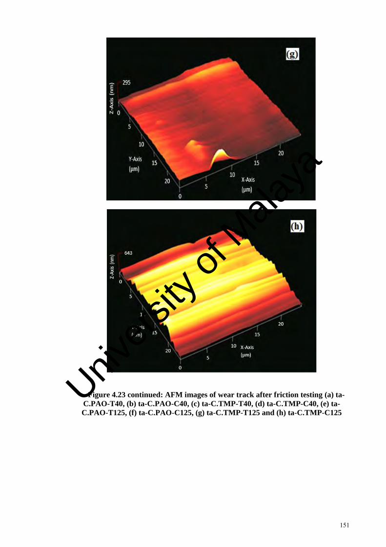
151
Figure 4.23 continued: AFM images of wear track after friction testing (a) ta-
C.PAO-T40, (b) ta-C.PAO-C40, (c) ta-C.TMP-T40, (d) ta-C.TMP-C40, (e) ta-
C.PAO-T125, (f) ta-C.PAO-C125, (g) ta-C.TMP-T125 and (h) ta-C.TMP-C125
Univers
ity of
Mala
ya

152
ta-C.P
AO-C40
ta-C.P
AO-T40
ta-C.TMP-C
40
ta-C.TMP-T
40
ta-C.P
AO-C125
ta-C.P
AO-T125
ta-C.TMP-C
125
ta-C.TMP-T
125
0
10
20
30
40
50
60
70
Ave
rage
Sur
face
Rou
ghne
ss (n
m)
Figure 4.24: Average surface roughness at the wear track after friction testing
The friction and wear behavior of a tribo system is also dependent on the counter
surface body (Stachowiak & Batchelor, 2013). In our case, the counter body is a steel
ball. Counter ball wear for textured and un-textured tetrahedral amorphous carbon coated
samples can be seen in Figure 4.27. Severe scratches indicating abrasive wearing can be
observed in the case of samples ta-C.PAO-C125 and ta-C.TMP-C125 (Figure 4.27 b and
4.27 d). Counter balls which rubbed against textured samples ta-C.PAO-T125 and ta-
C.TMP-T125 showed slight grooves (Figure 4.27 a and 4.27 c). These results can be due
to micro textures which can provide lubricant and capture the wear particles from the
contact, thus lowering counter surface excessive abrasive wearing. At higher
temperatures, textured coated samples showed higher ball wear coefficient compared to
un-textured coating (Figure 4.21). This behavior was also observed in the case of
amorphous hydrogenated carbon coating (section 4.3.2.2). Formation of graphitic transfer
film can be responsible for lowering wear rate of counter body (Mobarak et al., 2014).
Univers
ity of
Mala
ya

153
The increase in counter ball wear rate for textured coated samples can be related to
reduced graphitization transformation caused by the textures. As discussed in Raman
spectroscopy section (Section 4.4.2.1), textured samples show lower graphitization
transformation, whereas higher graphitization transformation was observed in case of un-
textured tetrahedral amorphous carbon coated samples.
-+
Slight abrasion
Univers
ity of
Mala
ya

154
Figure 4.25 continued: SEM images of steel balls which rub against (a) ta-
C.PAO-T125, (b) ta-C.PAO-C125, (c) ta-C.TMP-T125 and (d) ta-C.TMP-C125
Slight abrasion
Univers
ity of
Mala
ya

155
Table 4.4: EDX analysis of un-textured/textured tetrahedral amorphous
coated samples at various temperatures
Specimen Elements (Atomic %)
C O Cr Fe Si Mn
ta-C as deposited 97.93 0.08 - 1.99 - -
ta-C.PAO-T40 94.85 2.01 0 .03 3.11 - -
ta-C.PAO-C40 90.70 2.43 0.09 6.78 - -
ta-C.TMP-T40 94.61 2.33 0.08 2.98 - -
ta-C.TMP-C40 91.56 2.57 0.06 5.81 - -
ta-C.PAO-T125 93.72 3.01 0.04 3.23 - -
ta-C.PAO-C125 89.62 3.2 0.05 7.13 - -
ta-C.TMP-T125 93.91 2.99 0.08 3.02 - -
ta-C.TMP-C125 88.7 3.13 0.05 8.12 - -
Univers
ity of
Mala
ya

156
4.4.3 Comparison of tribological behavior of laser textured amorphous
hydrogenated and tetrahedral amorphous carbon coatings at various
temperatures
As observed in sections 4.3 and 4.4, laser micro texturing improved the tribological
performance of amorphous hydrogenated and tetrahedral amorphous carbon coatings in
PAO and palm based TMP lubrication. In this section, comparison is conducted between
laser textured amorphous hydrogenated and tetrahedral amorphous carbon coatings for
tribological performance. Figure 4.28 shows the average coefficient of friction of both
textured coatings at temperatures 40, 80 and 125 ºC in PAO and palm based TMP
lubricant. Samples ta-C.TMP-T40 and ta-C.PAO-T40 showed the lower average
coefficient of friction values of 0.057 and 0.061 compared to 0.063 and 0.070 shown by
samples TMP-T40 and PAO-T40. Figure 4.29 shows the wear coefficient of textured
coating at 40, 80 and 125 ºC in PAO and palm based TMP lubricant. Lower wear
coefficient can be observed in the case of samples ta-C.TMP-T40 and ta-C.PAO-T40
compared to samples TMP-T40 and PAO-T40.
At 80 ºC temperature, samples ta-C.TMP-T80 and ta-C.PAO-T80 showed lower
average coefficient of friction of 0.077 and 0.078 compared to average coefficient of
friction of 0.115 and 0.119 shown by samples TMP-T80 and PAO-T80. Wear coefficient
was also lower for samples ta-C.TMP-T80 and ta-C.PAO-T80 compared to samples
TMP-T80 and PAO-T80. Similar to tests conducted at 40 and 80 ºC, at 125 ºC the
samples ta-C.TMP-T125 and ta-C.PAO-T125 showed lower coefficient of friction of
0.084 and 0.081 compared to average coefficient of friction of 0.14 and 0.13 shown by
TMP-T125 and PAO-T125. Additionally, wear coefficient was also lower for samples ta-
C.TMP-T125 and ta-C.PAO-T125 compared to samples TMP-T125 and PAO-T125.
Univers
ity of
Mala
ya
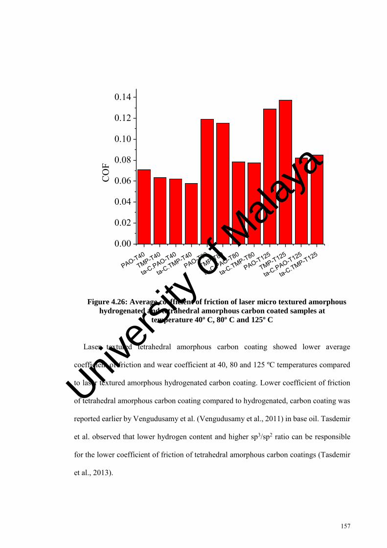
157
PAO-T40
TMP-T40
ta-C.P
AO-T40
ta-C.TMP-T
40
PAO-T80
TMP-T80
ta-C.P
AO-T80
ta-C.TMP-T
80
PAO-T125
TMP-T125
ta-C.P
AO-T125
ta-C.TMP-T
125
0.00
0.02
0.04
0.06
0.08
0.10
0.12
0.14C
OF
Figure 4.26: Average coefficient of friction of laser micro textured amorphous
hydrogenated and tetrahedral amorphous carbon coated samples at
temperature 40º C, 80º C and 125º C
Laser textured tetrahedral amorphous carbon coating showed lower average
coefficient of friction and wear coefficient at 40, 80 and 125 ºC temperatures compared
to laser textured amorphous hydrogenated carbon coating. Lower coefficient of friction
of tetrahedral amorphous carbon coating compared to hydrogenated, carbon coating was
reported earlier by Vengudusamy et al. (Vengudusamy et al., 2011) in base oil. Tasdemir
et al. observed that lower hydrogen content and higher sp3/sp2 ratio can be responsible
for the lower coefficient of friction of tetrahedral amorphous carbon coatings (Tasdemir
et al., 2013).
Univers
ity of
Mala
ya

158
Laser textured tetrahedral amorphous carbon coating showed the lower wear
coefficient than laser textured hydrogenated amorphous carbon coating. Lower wear
coefficient can be related to the higher H/E ratio of tetrahedral amorphous carbon coating.
The H/E ratio of the coating is hypothesized to represent its wear behavior (Pintaude,
2013). The coating possesses maximum tensile elastic stress if H/E ratio is higher (Jiang
et al., 1989), and therefore, can be related to high wear resistance. As tetrahedral
amorphous carbon coating had higher H/E ratio compared to be amorphous hydrogenated
carbon coating, higher wear resistance in case of laser textured tetrahedral amorphous
carbon coating can be expected.
PAO-T40
TMP-T40
ta-C.PAO-T40
ta-C.TMP-T40
PAO-T80
TMP-T80
ta-C.PAO-T80
ta-C.TMP-T80
PAO-T125
TMP-T125
ta-C.PAO-T125
ta-C.TMP-T125
0
10
20
30
40
50
60
70
80
90
Wea
r Coe
ffici
ent (
10 -8
mm
3 /Nm
)
Figure 4.27: Wear coefficient of laser micro textured amorphous
hydrogenated and tetrahedral amorphous carbon coated samples at
temperature 40º C, 80º C and 125º C
Univers
ity of
Mala
ya

159
CHAPTER 5: CONCLUSIONS AND RECOMMENDATIONS
5.1 Conclusions
Tribological effect of laser textured density, diameter and depth were evaluated on
amorphous hydrogenated carbon coating. The tribological behavior of laser textured and
un-textured amorphous hydrogenated carbon coating and tetrahedral carbon coating were
evaluated at various temperatures in the presence of PAO, and palm based TMP
lubrication. Based on the results of these studies following conclusions can be drawn.
1. Textured amorphous hydrogenated carbon coating showed the minimum
coefficient of friction at 30 % dimple density compared to 10 % density for all
combinations of diameters and depths. In the case of 20 % dimple density, dimple
diameter of 100 µm and depth of 6 µm showed lowest coefficient of friction
compared to all other samples.
Sample Dn20Di100Dp6 yielded the lowest average coefficient of friction
and wear coefficient among all the tested amorphous hydrogenated carbon coated
samples. Dimple's diameter of 100 µm showed the lowest wear coefficient at all
dimple densities tested. If the diameter exceeded 100 µm, wear resistance is
reduced. The optimum dimple diameter depends on contact width-to-dimple
diameter ratio. Contact load per unit area, coefficient of friction, and wear
coefficient increase if dimple diameter and contact width are nearly similar.
2. Laser textured amorphous hydrogenated carbon showed higher wear resistance
compared to un-textured coating at 40 ºC, 80 ºC and 125 ºC in the presence of
PAO and palm based TMP lubrication.
At 40 ºC temperature, lower coefficient of friction can be observed for
laser textured amorphous hydrogenated carbon. However, coefficient of friction
was higher as temperature was increased to 80 ºC and 125 ºC for both lubricants
tested.
Univers
ity of
Mala
ya

160
Coefficient of friction trends for laser textured amorphous hydrogenated
carbon coating was stable at 40 ºC, 80 ºC and 125 ºC compared to un-textured
coatings. The stability can be attributed to the fact that micro textures reduced the
abrasive wearing by capturing the wear debris from the interface. This was
confirmed with scanning electron microscope and atomic force microscope.
Palm based TMP lubricant showed lower coefficient of friction and wear
coefficient compared to PAO lubricant for laser textured and un-textured
amorphous hydrogenated carbon coatings at 40 ºC and 80 ºC temperature. As the
temperature increased to 125 ºC, palm based TMP showed higher coefficient of
friction and wear coefficient than PAO lubricant.
The lower coefficient of friction shown by un-textured amorphous
hydrogenated carbon coatings at 80 ºC and 125 ºC can be attributed to
graphitization phenomenon.
3. Tribological behavior of laser textured tetrahedral amorphous carbon coating was
similar to that of laser textured amorphous hydrogenated carbon coating at 40 ºC,
80 ºC and 125 ºC. Laser textured tetrahedral amorphous carbon coating showed
higher wear resistance compared to un-textured tetrahedral amorphous carbon
coating at 40 ºC, 80 ºC and 125 ºC.
As the temperature was increased from 40 ºC, coefficient of friction was
higher in the case of laser textured tetrahedral carbon coating compared to un-
textured coating, whereas wear coefficient remained lower throughout the
temperature range. Lower coefficient of friction at 80 ºC and 125 ºC temperature
in the case of un-textured tetrahedral amorphous carbon coating was due to
graphitization phenomenon.
At 40 ºC and 80 ºC temperature, Palm based TMP ester showed lower
coefficient of friction and wear coefficient in the case of tetrahedral carbon
Univers
ity of
Mala
ya
161
coating compared to PAO lubricant. However, at 125 ºC PAO showed better
coefficient of friction and wear coefficient. This result was similar for both
coatings tested.
Laser textured tetrahedral amorphous carbon coating showed lower
coefficient of friction and wear coefficient at 40 ºC, 80 ºC and 125 ºC compared
to laser textured amorphous hydrogenated carbon coating in both PAO and palm
based TMP lubrication. Coefficient of friction and wear coefficient increased for
both laser textured coatings with the increase in temperature.
Laser textured tetrahedral carbon coating (non-hydrogenated) can be used
to improve friction and wear behavior of automotive components compared to
laser textured amorphous hydrogenated carbon coating.
5.2 Recommendations for future work
1. Effect of various micro texture shapes on the tribological performance of
tetrahedral amorphous carbon coating should be investigated. Until now most of
the experimental work on surface texturing has been conducted using spherical
shaped dimples. The reason for this research trend was that it is easier and less
expensive to form spherical shaped dimples compared to other shapes.
Theoretically, researchers have found that shape of textures effect the tribological
performance (Nanbu, et al., 2008). Various shapes such as ellipse, rectangle etc.
should also be experimentally investigated with tetrahedral amorphous carbon
coating. Other shapes may enhance the tribological performance of coating.
2. Tribological performance of nano and micro textured tetrahedral amorphous
carbon coating should be investigated and compared. Previously, in the case of
cutting tool application, micro and nano textures have been found to show
different tribological behavior (Enomoto et al., 2012; Kawasegi et al., 2009). In
the case of automotive applications, this has to be investigated to find out whether
Univers
ity of
Mala
ya

162
it is tribologically beneficial to use nano textured or micro textured tetrahedral
amorphous carbon coating.
3. Tribological effect of solid lubricants such as tungsten disulfide and molybdenum
disulfide filled micro and nano textured tetrahedral amorphous carbon coating
should be investigated. Previously, researchers have found that solid lubricant
filled textured steel show lower coefficient of friction and higher wear resistance
than un-textured samples (Segu et al., 2013). They observed that textures provide
solid lubricant at the interface and increase the adhesion of solid lubricant coating.
As the properties of DLC coatings deteriorate with temperature, combination of
surface texturing and solid lubricant can further enhance their tribological
performance.
Univers
ity of
Mala
ya

163
REFERENCES
Abboud, J. H., Benyounis, K. Y., Olabi, A. G., & Hashmi, M. S. J. (2007). Laser surface treatments of iron-based substrates for automotive application. Journal of Materials Processing Technology, 182(1-3), 427-431.
Al Mahmud, K., Kalam, M., Masjuki, H., Mobarak, H., & Zulkifli, N. (2015). An updated overview of diamond-like carbon coating in tribology. Critical Reviews in Solid State and Materials Sciences, 40(2), 90-118.
Al Mahmud, K. A. H., Varman, M., Kalam, M. A., Masjuki, H. H., Mobarak, H. M., & Zulkifli, N. W. M. (2014). Tribological characteristics of amorphous hydrogenated (a-C:H) and tetrahedral (ta-C) diamond-like carbon coating at different test temperatures in the presence of commercial lubricating oil. Surface and Coatings Technology.
Amanov, A., Cho, I. S., Pyoun, Y. S., Lee, C. S., & Park, I. G. (2012). Micro-dimpled surface by ultrasonic nanocrystal surface modification and its tribological effects. Wear, 286–287, 136-144.
Amanov, A., Tsuboi, R., Oe, H., & Sasaki, S. (2013). The influence of bulges produced by laser surface texturing on the sliding friction and wear behavior. Tribology International, 60, 216-223.
Amanov, A., Watabe, T., Tsuboi, R., & Sasaki, S. (2013). Improvement in the tribological characteristics of Si-DLC coating by laser surface texturing under oil-lubricated point contacts at various temperatures. Surface and Coatings Technology, 232, 549-560.
Arbain, N. H., & Salimon, J. (2010). Synthesis and characterization of ester trimethylolpropane based Jatropha curcas oil as biolubricant base stocks. Journal of Science and Technology, 2(2).
Austin, L. B. (2014). Evaluation and optimisation of diamond-like carbon for tribological applications: University of Leeds.
Aziz, N. A. M., Yunus, R., Rashid, U., & Zulkifli, N. W. M. (2016). Temperature effect on tribological properties of polyol ester-based environmentally adapted lubricant. Tribology International, 93, 43-49.
Bewilogua, K., & Hofmann, D. (2014). History of diamond-like carbon films—from first experiments to worldwide applications. Surface and Coatings Technology, 242, 214-225.
Bhushan, B. (2013). Principles and applications of tribology: John Wiley & Sons.
Bolander, N. W., & Sadeghi, F. (2006). Surface modification for piston ring and liner (Vol. 134).
Bremond, F., Fournier, P., & Platon, F. (2003). Test temperature effect on the tribological behavior of DLC-coated 100C6-steel couples in dry friction. Wear, 254(7–8), 774-783.
Univers
ity of
Mala
ya

164
Brizmer, V., Kligerman, Y., & Etsion, I. (2003). A laser surface textured parallel thrust bearing. Tribology Transactions, 46(3), 397-403.
Caciu, C., Decenciere, E., & Jeulin, D. (2008). Parametric Optimization of Periodic Textured Surfaces for Friction Reduction in Combustion Engines. Tribology Transactions, 51(4), 533-541.
Cannon, A. H., & King, W. P. (2009). Casting metal microstructures from a flexible and reusable mold. Journal of Micromechanics and Microengineering, 19(9), 095016.
Canter, N. (2009). Special report: Boundary lubricity additives. Tribology & Lubrication Technology, 65(9), 10.
Casiraghi, C., Ferrari, A. C., & Robertson, J. (2005). Raman spectroscopy of hydrogenated amorphous carbons. Physical Review B, 72(8), 085401.
Chang, W., Sun, J., Luo, X., Ritchie, J. M., & Mack, C. (2011). Investigation of microstructured milling tool for deferring tool wear. Wear, 271(9-10), 2433-2437.
Checo, H. M., Ausas, R. F., Jai, M., Cadalen, J.-P., Choukroun, F., & Buscaglia, G. C. (2014). Moving textures: Simulation of a ring sliding on a textured liner. Tribology International, 72, 131-142.
Chen, C.-Y., Chung, C.-J., Wu, B.-H., Li, W.-L., Chien, C.-W., Wu, P.-H., & Cheng, C.-W. (2012). Microstructure and lubricating property of ultra-fast laser pulse textured silicon carbide seals. Applied Physics a-Materials Science & Processing, 107(2), 345-350.
Churi, N. (2010). Rotary ultrasonic machining of hard-to-machine materials. (Doctor of Philosophy), Kansas State University, Manhattan, Kansas.
Coblas, D. G., Fatu, A., Maoui, A., & Hajjam, M. (2014). Manufacturing textured surfaces: State of art and recent developments. Proceedings of the Institution of Mechanical Engineers, Part J: Journal of Engineering Tribology, 229(1), 3-29.
da Silva, W. M., Suarez, M. P., Machado, A. R., & Costa, H. L. (2013). Effect of laser surface modification on the micro-abrasive wear resistance of coated cemented carbide tools. Wear, 302(1-2), 1230-1240.
Davis, R. F. (1991). Diamond films and coatings: development, properties, and applications.
Demas, N. G., Polycarpou, A. A., & Conry, T. F. (2005). Tribological studies on scuffing due to the influence of carbon dioxide used as a refrigerant in compressors. Tribology Transactions, 48(3), 336-342.
Deng, J., Lian, Y., Wu, Z., & Xing, Y. (2013). Performance of femtosecond laser-textured cutting tools deposited with WS2 solid lubricant coatings. Surface and Coatings Technology, 222, 135-143.
Ding, Q., Wang, L., Hu, L., Hu, T., Wang, Y., & Zhang, Y. (2011). An explanation for laser-induced spallation effect in a-C:H films: Altered phase evolution route caused by hydrogen doping. Journal of Applied Physics, 109(1), 013501.
Univers
ity of
Mala
ya
165
Ding, Q., Wang, L., Wang, Y., Wang, S. C., Hu, L., & Xue, Q. (2010). Improved Tribological Behavior of DLC Films Under Water Lubrication by Surface Texturing. Tribology Letters, 41(2), 439-449.
Dong, C., Gu, Y., Zhong, M., Li, L., Sezer, K., Ma, M., & Liu, W. (2011). Fabrication of superhydrophobic Cu surfaces with tunable regular micro and random nano-scale structures by hybrid laser texture and chemical etching. Journal of Materials Processing Technology, 211(7), 1234-1240.
Donnet, C. (1998). Recent progress on the tribology of doped diamond-like and carbon alloy coatings: a review. Surface and Coatings Technology, 100–101(0), 180-186.
Donnet, C., & Erdemir, A. (2007). Tribology of diamond-like carbon films: fundamentals and applications: Springer Science & Business Media.
Dowson, D., & Higginson, G. (1959). A numerical solution to the elasto-hydrodynamic problem. Journal of mechanical engineering science, 1(1), 6-15.
Dumitru, G., Romano, V., Weber, H. P., Pimenov, S., Kononenko, T., Hermann, J., . . . Shupegin, M. (2003). Laser treatment of tribological DLC films. Diamond and Related Materials, 12(3-7), 1034-1040.
Enomoto, T., & Sugihara, T. (2010). Improving anti-adhesive properties of cutting tool surfaces by nano-/micro-textures. CIRP Annals - Manufacturing Technology, 59(1), 597-600.
Enomoto, T., & Sugihara, T. (2011). Improvement of Anti-Adhesive Properties of Cutting Tool by Nano/Micro Textures and Its Mechanism. Procedia Engineering, 19, 100-105.
Enomoto, T., Sugihara, T., Yukinaga, S., Hirose, K., & Satake, U. (2012). Highly wear-resistant cutting tools with textured surfaces in steel cutting. CIRP Annals - Manufacturing Technology, 61(1), 571-574.
Erdemir, A. (2001). The role of hydrogen in tribological properties of diamond-like carbon films. Surface and Coatings Technology, 146–147, 292-297.
Erdemir, A., & Fenske, G. R. (1996). Tribological Performance of Diamond and Diamondlike Carbon Films at Elevated Temperatures. Tribology Transactions, 39(4), 787-794.
Etsion, I. (2004). Improving tribological performance of mechanical components by laser surface texturing. Tribology Letters, 17(4), 733-737.
Etsion, I. (2005). State of the Art in Laser Surface Texturing. Journal of Tribology, 127(1), 248.
Etsion, I., & Burstein, L. (1996). A Model for Mechanical Seals with Regular Microsurface Structure. Tribology Transactions, 39(3), 677-683.
Etsion, I., Halperin, G., & Becker, E. (2006). The effect of various surface treatments on piston pin scuffing resistance. Wear, 261(7-8), 785-791.
Univers
ity of
Mala
ya

166
Etsion, I., & Sher, E. (2009). Improving fuel efficiency with laser surface textured piston rings. Tribology International, 42(4), 542-547.
Feldman, Y., Kligerman, Y., & Etsion, I. (2006). A Hydrostatic Laser Surface Textured Gas Seal. Tribology Letters, 22(1), 21-28.
Feldman, Y., Kligerman, Y., Etsion, I., & Haber, S. (2006). The Validity of the Reynolds Equation in Modeling Hydrostatic Effects in Gas Lubricated Textured Parallel Surfaces. Journal of Tribology, 128(2), 345.
Ferrari, A. C., & Robertson, J. (2000). Interpretation of Raman spectra of disordered and amorphous carbon. Physical Review B, 61(20), 14095-14107.
Ferraro, J. R. (2003). Introductory raman spectroscopy: Academic press.
Gadeschi, G. B., Backhaus, K., & Knoll, G. (2012). Numerical Analysis of Laser-Textured Piston-Rings in the Hydrodynamic Lubrication Regime. Journal of Tribology, 134(4), 041702.
Gao, F., Erdemir, A., & Tysoe, W. T. (2005). The Tribological Properties of Low-friction Hydrogenated Diamond-like Carbon Measured in Ultrahigh Vacuum. Tribology Letters, 20(3-4), 221-227.
Gao, Y., Wu, B., Zhou, Y., & Tao, S. (2011). A two-step nanosecond laser surface texturing process with smooth surface finish. Applied Surface Science, 257(23), 9960-9967.
Gellman, A. J., & Spencer, N. D. (2002). Surface chemistry in tribology. Proceedings of the Institution of Mechanical Engineers, Part J: Journal of Engineering Tribology, 216(6), 443-461.
Gharam, A. A., Lukitsch, M. J., Balogh, M. P., Irish, N., & Alpas, A. T. (2011). High temperature tribological behavior of W-DLC against aluminum. Surface and Coatings Technology, 206(7), 1905-1912.
Greco, A., Raphaelson, S., Ehmann, K., Wang, Q. J., & Lin, C. (2009). Surface Texturing of Tribological Interfaces Using the Vibromechanical Texturing Method. Journal of Manufacturing Science and Engineering, 131(6), 061005.
Grill, A. (1993). Review of the tribology of diamond-like carbon. Wear, 168(1), 143-153.
Grill, A. (1999). Diamond-like carbon: state of the art. Diamond and Related Materials, 8(2–5), 428-434.
Grill, A. (1999). Diamond-like carbon: state of the art. Diamond and Related Materials, 8(2), 428-434.
Hamilton, D. B., Walowit, J. A., & Allen, C. M. (1966). A Theory of Lubrication by Microirregularities. Journal of Fluids Engineering, 88(1), 177-185.
Handbook for Analytical Methods for Materials (2014). from http://www.mee-inc.com/
Univers
ity of
Mala
ya

167
Hao, L., Meng, Y., & Chen, C. (2014). Experimental investigation on effects of surface texturing on lubrication of initial line contacts. Lubrication Science, 26(5), 363-373.
Haque, T., Morina, A., Neville, A., Kapadia, R., & Arrowsmith, S. (2009). Effect of oil additives on the durability of hydrogenated DLC coating under boundary lubrication conditions. Wear, 266(1-2), 147-157.
Hauert, R. (2004). An overview on the tribological behavior of diamond-like carbon in technical and medical applications. Tribology International, 37(11–12), 991-1003.
Heinke, W., Leyland, A., Matthews, A., Berg, G., Friedrich, C., & Broszeit, E. (1995). Evaluation of PVD nitride coatings, using impact, scratch and Rockwell-C adhesion tests. Thin Solid Films, 270(1-2), 431-438.
Hironaka, S. (1984). Boundary lubrication and lubricants. Three bond technical news, 9, 1-6.
Hsu, S. M., Jing, Y., Hua, D., & Zhang, H. (2014). Friction reduction using discrete surface textures: principle and design. Journal of Physics D: Applied Physics, 47(33), 335307.
Hu, T., Hu, L., & Ding, Q. (2012). Effective solution for the tribological problems of Ti-6Al-4V: Combination of laser surface texturing and solid lubricant film. Surface and Coatings Technology, 206(24), 5060-5066.
Hutchings, I. M. (1992). Tribology: friction and wear of engineering materials.
Ing, T. C., Mohammed Rafiq, A., Azli, Y., & Syahrullail, S. (2012). The effect of temperature on the tribological behavior of RBD palm stearin. Tribology Transactions, 55(5), 539-548.
Jiang, X., Reichelt, K., & Stritzker, B. (1989). The hardness and Young’s modulus of amorphous hydrogenated carbon and silicon films measured with an ultralow load indenter. Journal of Applied Physics, 66(12), 5805-5808.
Jianxin, D., Ze, W., Yunsong, L., Ting, Q., & Jie, C. (2012). Performance of carbide tools with textured rake-face filled with solid lubricants in dry cutting processes. International Journal of Refractory Metals and Hard Materials, 30(1), 164-172.
Johnson, M., & Cote, P. (2006). Modeling Magnetron Sputter Deposition. Materials and Manufacturing Processes, 21(6), 628-633.
Kalin, M., Roman, E., Ožbolt, L., & Vižintin, J. (2010). Metal-doped (Ti, WC) diamond-like-carbon coatings: Reactions with extreme-pressure oil additives under tribological and static conditions. Thin Solid Films, 518(15), 4336-4344.
Kalin, M., Velkavrh, I., Vižintin, J., & Ožbolt, L. (2008). Review of boundary lubrication mechanisms of DLC coatings used in mechanical applications. Meccanica, 43(6), 623-637.
Univers
ity of
Mala
ya
168
Kalin, M., & Vižintin, J. (2006). A comparison of the tribological behaviour of steel/steel, steel/DLC and DLC/DLC contacts when lubricated with mineral and biodegradable oils. Wear, 261(1), 22-31.
Kalish, R., Lifshitz, Y., Nugent, K., & Prawer, S. (1999). Thermal stability and relaxation in diamond-like-carbon. A Raman study of films with different sp3 fractions (ta-C to aC). Applied physics letters, 74, 2936.
Kato, K. (2000). Wear in relation to friction—a review. Wear, 241(2), 151-157.
Kawasegi, N., Sugimori, H., Morimoto, H., Morita, N., & Hori, I. (2009). Development of cutting tools with microscale and nanoscale textures to improve frictional behavior. Precision Engineering, 33(3), 248-254.
Kelly, P. J., & Arnell, R. D. (2000). Magnetron sputtering: a review of recent developments and applications. Vacuum, 56(3), 159-172.
Kligerman, Y., & Etsion, I. (2001). Analysis of the Hydrodynamic Effects in a Surface Textured Circumferential Gas Seal. Tribology Transactions, 44(3), 472-478.
Kligerman, Y., Etsion, I., & Shinkarenko, A. (2005). Improving tribological performance of piston rings by partial surface texturing. Journal of Tribology-Transactions of the Asme, 127(3), 632-638.
Kligerman, Y., & Shinkarenko, A. (2011). The effect of tapered edges on lubrication regimes in surface-textured elastomer seals. Tribology International, 44(12), 2059-2066.
Kodali, D. R. (2002). High performance ester lubricants from natural oils. Industrial lubrication and tribology, 54(4), 165-170.
Komlenok, M. S., Arutyunyan, N. R., Kononenko, V. V., Zavedeev, E. V., Frolov, V. D., Chouprik, A. A., . . . Pimenov, S. M. (2016). Structure and friction properties of laser-patterned amorphous carbon films. Diamond and Related Materials, 65, 69-74.
Kononenko, T. V., Garnov, S. V., Pimenov, S. M., Konov, V. I., Romano, V., Borsos, B., & Weber, H. P. (2000). Laser ablation and micropatterning of thin TiN coatings. Applied Physics A, 71(6), 627-631.
Koshy, P., & Tovey, J. (2011). Performance of electrical discharge textured cutting tools. CIRP Annals - Manufacturing Technology, 60(1), 153-156.
Koskinen, J., Tapper, U., Andersson, P., Varjus, S., Kolehmainen, J., Tervakangas, S., & Buss, W. (2010). Friction reduction by texturing of DLC coatings sliding against steel under oil lubrication. Surface and Coatings Technology, 204(23), 3794-3797.
Kovalchenko, A., Ajayi, O., Erdemir, A., & Fenske, G. (2011). Friction and wear behavior of laser textured surface under lubricated initial point contact. Wear, 271(9-10), 1719-1725.
Krumpiegl, T., Meerkamm, H., Fruth, W., Schaufler, C., Erkens, G., & Böhner, H. (1999). Amorphous carbon coatings and their tribological behaviour at high
Univers
ity of
Mala
ya

169
temperatures and in high vacuum. Surface and Coatings Technology, 120–121, 555-560.
Kumar, A., & Sharma, S. (2011). Potential non-edible oil resources as biodiesel feedstock: An Indian perspective. Renewable and Sustainable Energy Reviews, 15(4), 1791-1800.
Kuršelis, K., Kiyan, R., & Chichkov, B. N. (2012). Formation of corrugated and porous steel surfaces by femtosecond laser irradiation. Applied Surface Science, 258(22), 8845-8852.
Lei, S., Devarajan, S., & Chang, Z. (2009). A study of micropool lubricated cutting tool in machining of mild steel. Journal of Materials Processing Technology, 209(3), 1612-1620.
Li, J., Xiong, D., Wu, H., Huang, Z., Dai, J., & Tyagi, R. (2010). Tribological Properties of Laser Surface Texturing and Molybdenizing Duplex-Treated Ni-Base Alloy. Tribology Transactions, 53(2), 195-202.
Li, Y., Deng, J., Chai, Y., & Fan, W. (2016). Surface textures on cemented carbide cutting tools by micro EDM assisted with high-frequency vibration. The International Journal of Advanced Manufacturing Technology, 82(9-12), 2157-2165.
Ling, T. D., Liu, P., Xiong, S., Grzina, D., Cao, J., Wang, Q. J., . . . Talwar, R. (2013). Surface Texturing of Drill Bits for Adhesion Reduction and Tool Life Enhancement. Tribology Letters, 52(1), 113-122.
Liu, H., Wan, D., & Hu, D. (2009). Microstructure and wear behavior of laser-textured and micro-alloyed Co-based WC and TiC composite sintered-carbide coating. Journal of Materials Processing Technology, 209(2), 805-810.
Liu, Y., Erdemir, A., & Meletis, E. I. (1996). An investigation of the relationship between graphitization and frictional behavior of DLC coatings. Surface and Coatings Technology, 86–87, Part 2(0), 564-568.
Liu, Y., & Meletis, E. (1997). Evidence of graphitization of diamond-like carbon films during sliding wear. Journal of Materials Science, 32(13), 3491-3495.
Lu, X., & Khonsari, M. M. (2007). An experimental investigation of dimple effect on the stribeck curve of journal bearings. Tribology Letters, 27(2), 169-176.
Marian, V. G., Gabriel, D., Knoll, G., & Filippone, S. (2011). Theoretical and Experimental Analysis of a Laser Textured Thrust Bearing. Tribology Letters, 44(3), 335-343.
Masuzawa, T. (2000). State of the Art of Micromachining. CIRP Annals - Manufacturing Technology, 49(2), 473-488.
Meijer, J. (2004). Laser beam machining (LBM), state of the art and new opportunities. Journal of Materials Processing Technology, 149(1-3), 2-17.
Mishra, S. P., & Polycarpou, A. A. (2011). Tribological studies of unpolished laser surface textures under starved lubrication conditions for use in air-conditioning and refrigeration compressors. Tribology International, 44(12), 1890-1901.
Univers
ity of
Mala
ya

170
Mistry, K. K., Morina, A., & Neville, A. (2011). A tribochemical evaluation of a WC–DLC coating in EP lubrication conditions. Wear, 271(9-10), 1739-1744.
Mobarak, H., Masjuki, H., Mohamad, E. N., Kalam, M., Rashedul, H., Rashed, M., & Habibullah, M. (2014). Tribological properties of amorphous hydrogenated (aC: H) and hydrogen-free tetrahedral (ta-C) diamond-like carbon coatings under jatropha biodegradable lubricating oil at different temperatures. Applied Surface Science, 317, 581-592.
Mobarak, H. M., Niza Mohamad, E., Masjuki, H. H., Kalam, M. A., Al Mahmud, K. A. H., Habibullah, M., & Ashraful, A. M. (2014). The prospects of biolubricants as alternatives in automotive applications. Renewable and Sustainable Energy Reviews, 33, 34-43.
Mourier, L., Mazuyer, D., Lubrecht, A. A., & Donnet, C. (2006). Transient increase of film thickness in micro-textured EHL contacts. Tribology International, 39(12), 1745-1756.
Mourier, L., Mazuyer, D., Ninove, F. P., & Lubrecht, A. A. (2010). Lubrication mechanisms with laser-surface-textured surfaces in elastohydrodynamic regime. Proceedings of the Institution of Mechanical Engineers Part J-Journal of Engineering Tribology, 224(J8), 697-711.
Nakano, M., Korenaga, A., Korenaga, A., Miyake, K., Murakami, T., Ando, Y., . . . Sasaki, S. (2007). Applying micro-texture to cast iron surfaces to reduce the friction coefficient under lubricated conditions. Tribology Letters, 28(2), 131-137.
Nanbu, T., Ren, N., Yasuda, Y., Zhu, D., & Wang, Q. J. (2008). Micro-Textures in Concentrated Conformal-Contact Lubrication: Effects of Texture Bottom Shape and Surface Relative Motion. Tribology Letters, 29(3), 241-252.
Neves, D., Diniz, A. E., & de Lima, M. S. F. (2006). Efficiency of the laser texturing on the adhesion of the coated twist drills. Journal of Materials Processing Technology, 179(1-3), 139-145.
Neville, A., Morina, A., Haque, T., & Voong, M. (2007). Compatibility between tribological surfaces and lubricant additives—How friction and wear reduction can be controlled by surface/lube synergies. Tribology International, 40(10-12), 1680-1695.
Nguyen, T., & Butler, D. (2005). Simulation of precision grinding process, part 1: generation of the grinding wheel surface. International Journal of Machine Tools and Manufacture, 45(11), 1321-1328.
Obikawa, T., Kamio, A., Takaoka, H., & Osada, A. (2011). Micro-texture at the coated tool face for high performance cutting. International Journal of Machine Tools and Manufacture, 51(12), 966-972.
Oksanen, J., Hakala, T. J., Tervakangas, S., Laakso, P., Kilpi, L., Ronkainen, H., & Koskinen, J. (2014). Tribological properties of laser-textured and ta-C coated surfaces with burnished WS2 at elevated temperatures. Tribology International, 70, 94-103.
Univers
ity of
Mala
ya

171
Peng, X. L., Barber, Z. H., & Clyne, T. W. (2001). Surface roughness of diamond-like carbon films prepared using various techniques. Surface and Coatings Technology, 138(1), 23-32.
Pettersson, U., & Jacobson, S. (2003). Influence of surface texture on boundary lubricated sliding contacts. Tribology International, 36(11), 857-864.
Pettersson, U., & Jacobson, S. (2004). Friction and Wear Properties of Micro Textured DLC Coated Surfaces in Boundary Lubricated Sliding. Tribology Letters, 17(3), 553-559.
Pettersson, U., & Jacobson, S. (2007). Textured surfaces for improved lubrication at high pressure and low sliding speed of roller/piston in hydraulic motors. Tribology International, 40(2), 355-359.
Pinkus, O., & Sternlicht, B. (1961). Theory of hydrodynamic lubrication: McGraw-Hill.
Pintaude, G. (2013). Introduction of the Ratio of the Hardness to the Reduced Elastic Modulus for Abrasion Tribology - Fundamentals and Advancements (pp. 217-230): InTech.
Puchi-Cabrera, E. S., Staia, M. H., Ochoa-Pérez, E. A., Teer, D. G., Santana-Méndez, Y. Y., La Barbera-Sosa, J. G., . . . Lesage, J. (2010). Fatigue behavior of a 316L stainless steel coated with a DLC film deposited by PVD magnetron sputter ion plating. Materials Science and Engineering: A, 527(3), 498-508.
Qiu, M., Bailey, B. N., Stoll, R., & Raeymaekers, B. (2014). The accuracy of the compressible Reynolds equation for predicting the local pressure in gas-lubricated textured parallel slider bearings. Tribology International, 72, 83-89.
Qiu, M., Delic, A., & Raeymaekers, B. (2012). The Effect of Texture Shape on the Load-Carrying Capacity of Gas-Lubricated Parallel Slider Bearings. Tribology Letters, 48(3), 315-327.
Qiu, M., Minson, B. R., & Raeymaekers, B. (2013). The effect of texture shape on the friction coefficient and stiffness of gas-lubricated parallel slider bearings. Tribology International, 67, 278-288.
Qiu, Y. K., M.M. (2011a). Experimental investigation of tribological performance of laser textured stainless steel rings. Tribology International, 44(5), 635-644.
Qiu, Y. K., M.M. (2011b). Performance Analysis of Full-Film Textured Surfaces With Consideration of Roughness Effects. Journal of Tribology, 133(2), 021704.
Rabinowicz, E. (1995). Adhesive wear. Friction and Wear of Materials, 143-190.
Rahmani, R., Mirzaee, I., Shirvani, A., & Shirvani, H. (2010). An analytical approach for analysis and optimisation of slider bearings with infinite width parallel textures. Tribology International, 43(8), 1551-1565.
Ramesh, A., Akram, W., Mishra, S. P., Cannon, A. H., Polycarpou, A. A., & King, W. P. (2013). Friction characteristics of microtextured surfaces under mixed and hydrodynamic lubrication. Tribology International, 57, 170-176.
Univers
ity of
Mala
ya

172
Robertson, J. (1986). Amorphous carbon. Advances in Physics, 35(4), 317-374.
Robertson, J. (1991). Hard amorphous (diamond-like) carbons. Progress in Solid State Chemistry, 21(4), 199-333.
Robertson, J. (2002). Diamond-like amorphous carbon. Materials Science and Engineering: R: Reports, 37(4–6), 129-281.
Robiah, Y. l.-R., Ikuye, A., Indris, S., & A Ooi, T. (2003). Preparation and characterization of trimethylolpropane esters from palm kernel oil methyl esters.
Römer, G. R. B. E., Huis in’t Veld, A. J., Meijer, J., & Groenendijk, M. N. W. (2009). On the formation of laser induced self-organizing nanostructures. CIRP Annals - Manufacturing Technology, 58(1), 201-204.
Ronen, A., Etsion, I., & Kligerman, Y. (2001). Friction-Reducing Surface-Texturing in Reciprocating Automotive Components. Tribology Transactions, 44(3), 359-366.
Ronkainen, H. (2001). Tribological properties of hydrogenated and hydrogen-free diamond-like carbon coatings. Technical Research Centre of Finland. Publications(Finland), 434, 3-52.
Ronkainen, H., & Holmberg, K. (2008). Environmental and thermal effects on the tribological performance of DLC coatings Tribology of diamond-like carbon films (pp. 155-200): Springer.
Ronkainen, H., Koskinen, J., Varjus, S., & Holmberg, K. (1999). Load-carrying capacity evaluation of coating/substrate systems for hydrogen-free and hydrogenated diamond-like carbon films. Tribology Letters, 6(2), 63-73.
Ronkainen, H., Varjus, S., Koskinen, J., & Holmberg, K. (2001). Differentiating the tribological performance of hydrogenated and hydrogen-free DLC coatings. Wear, 249(3–4), 260-266.
Roy, T., Choudhury, D., Bin Mamat, A., & Pingguan-Murphy, B. (2014). Fabrication and characterization of micro-dimple array on Al2O3 surfaces by using a micro-tooling. Ceramics International, 40(1), 2381-2388.
Rudnick, L. R., & Shubkin, R. L. (1999). Synthetic lubricants and high-performance functional fluids, revised and expanded: CRC Press.
Ryk, G., & Etsion, I. (2006). Testing piston rings with partial laser surface texturing for friction reduction. Wear, 261(7-8), 792-796.
Ryk, G., Kligerman, Y., & Etsion, I. (2002). Experimental Investigation of Laser Surface Texturing for Reciprocating Automotive Components. Tribology Transactions, 45(4), 444-449.
Ryk, G., Kligerman, Y., Etsion, I., & Shinkarenko, A. (2005). Experimental Investigation of Partial Laser Surface Texturing for Piston-Ring Friction Reduction. Tribology Transactions, 48(4), 583-588.
Univers
ity of
Mala
ya

173
Sánchez-López, J. C., Erdemir, A., Donnet, C., & Rojas, T. C. (2003). Friction-induced structural transformations of diamondlike carbon coatings under various atmospheres. Surface and Coatings Technology, 163–164(0), 444-450.
Schreck, S., & Zum Gahr, K. H. (2005). Laser-assisted structuring of ceramic and steel surfaces for improving tribological properties. Applied Surface Science, 247(1-4), 616-622.
Segu, D. Z., Kim, J.-H., Choi, S. G., Jung, Y.-S., & Kim, S.-S. (2013). Application of Taguchi techniques to study friction and wear properties of MoS2 coatings deposited on laser textured surface. Surface and Coatings Technology, 232, 504-514.
Semenov, A. P., & Khrushchov, M. M. (2010). Influence of environment and temperature on tribological behavior of diamond and diamond-like coatings. Journal of Friction and Wear, 31(2), 142-158.
Shah, S., Moser, B., & Sharma, B. (2010). Glycerol Tri-Ester Derivatives as Diluent to Improve Low Temperature Properties of Vegetable Oils.
Shukla, P., Waugh, D., Lawrence, J., & Vilar, R. (2016). Laser surface structuring of ceramics, metals and polymers for biomedical applications: a review. Laser Surface Modification of Biomaterials: Techniques and Applications, 281.
Shum, P. W., Zhou, Z. F., & Li, K. Y. (2013). Investigation of the tribological properties of the different textured DLC coatings under reciprocating lubricated conditions. Tribology International, 65, 259-264.
Singh, D., & Singh, S. P. (2010). Low cost production of ester from non edible oil of Argemone mexicana. Biomass and Bioenergy, 34(4), 545-549.
Siripuram, R. B., & Stephens, L. S. (2004). Effect of Deterministic Asperity Geometry on Hydrodynamic Lubrication. Journal of Tribology, 126(3), 527-534.
So, H., & Chen, C. H. (2005). Effects of micro-wedges formed between parallel surfaces on mixed lubrication – Part II: modeling. Tribology Letters, 19(2), 83-91.
Song, H., Ji, L., Li, H., Liu, X., Zhou, H., Liu, L., & Chen, J. (2014). Improving the tribological performance of a-C:H film in a high vacuum by surface texture. Journal of Physics D: Applied Physics, 47(23), 235301.
Stachowiak, G., & Batchelor, A. W. (2013). Engineering tribology: Butterworth-Heinemann.
Sugihara, T., & Enomoto, T. (2009). Development of a cutting tool with a nano/micro-textured surface—Improvement of anti-adhesive effect by considering the texture patterns. Precision Engineering, 33(4), 425-429.
Sugihara, T., & Enomoto, T. (2012). Improving anti-adhesion in aluminum alloy cutting by micro stripe texture. Precision Engineering, 36(2), 229-237.
Sugihara, T., & Enomoto, T. (2013). Crater and flank wear resistance of cutting tools having micro textured surfaces. Precision Engineering, 37(4), 888-896.
Univers
ity of
Mala
ya

174
Sutton, D. C., Limbert, G., Stewart, D., & Wood, R. J. K. (2013). The friction of diamond-like carbon coatings in a water environment. Friction, 1(3), 210-221.
Tanu Suryadi, K., Jian Huei, C., Hong Yee, L., & Sujeet, K. S. (2010). Texturing of UHMWPE surface via NIL for low friction and wear properties. Journal of Physics D: Applied Physics, 43(1), 015301.
Tasdemir, H. A., Wakayama, M., Tokoroyama, T., Kousaka, H., Umehara, N., Mabuchi, Y., & Higuchi, T. (2013). Ultra-low friction of tetrahedral amorphous diamond-like carbon (ta-C DLC) under boundary lubrication in poly alpha-olefin (PAO) with additives. Tribology International, 65, 286-294.
Taylor, C. M. (1993). Engine tribology (Vol. 26): Elsevier.
Tomanik, E. (2013). Modelling the hydrodynamic support of cylinder bore and piston rings with laser textured surfaces. Tribology International, 59, 90-96.
Tønder, K. (2010). Dimpled pivoted plane bearings: Modified coefficients. Tribology International, 43(12), 2303-2307.
Tseng, A. A. (2004). Recent developments in micromilling using focused ion beam technology. Journal of Micromechanics and Microengineering, 14(4), R15-R34.
Tung, S. C., & McMillan, M. L. (2004). Automotive tribology overview of current advances and challenges for the future. Tribology International, 37(7), 517-536.
Uhlmann, E., Piltz, S., & Doll, U. (2005). Machining of micro/miniature dies and moulds by electrical discharge machining—Recent development. Journal of Materials Processing Technology, 167(2-3), 488-493.
Usman, A., & Park, C. W. (2016). Optimizing the tribological performance of textured piston ring–liner contact for reduced frictional losses in SI engine: Warm operating conditions. Tribology International, 99, 224-236.
Vandoni, L., Demir, A., Previtali, B., Lecis, N., & Ugues, D. (2012). Wear Behavior of Fiber Laser Textured TiN Coatings in a Heavy Loaded Sliding Regime. Materials, 5(12), 2360-2382.
Vanhulsel, A., Blanpain, B., Celis, J.-P., Roos, J., Dekempeneer, E., & Smeets, J. (1998). Study of the wear behaviour of diamond-like coatings at elevated temperatures. Surface and Coatings Technology, 98(1), 1047-1052.
Velkavrh, I., Kalin, M., & Vizintin, J. (2008). The performance and mechanisms of DLC-coated surfaces in contact with steel in boundary-lubrication conditions: a review. Strojniški vestnik, 54(3), 189-206.
Vengudusamy, B., Mufti, R. A., Lamb, G. D., Green, J. H., & Spikes, H. A. (2011). Friction properties of DLC/DLC contacts in base oil. Tribology International, 44(7–8), 922-932.
Veverkova, J., & Hainsworth, S. V. (2008). Effect of temperature and counterface on the tribological performance of W-DLC on a steel substrate. Wear, 264(7–8), 518-525.
Univers
ity of
Mala
ya

175
Vilhena, L. M., Sedlaček, M., Podgornik, B., Vižintin, J., Babnik, A., & Možina, J. (2009). Surface texturing by pulsed Nd:YAG laser. Tribology International, 42(10), 1496-1504.
Vincent, C., Monteil, G., Barriere, T., & Gelin, J. C. (2008). Control of the quality of laser surface texturing. Microsystem Technologies, 14(9-11), 1553-1557.
Volinsky, A. A., Moody, N. R., & Gerberich, W. W. (2002). Interfacial toughness measurements for thin films on substrates. Acta Materialia, 50(3), 441-466.
Wakuda, M., Yamauchi, Y., Kanzaki, S., & Yasuda, Y. (2003). Effect of surface texturing on friction reduction between ceramic and steel materials under lubricated sliding contact. Wear, 254(3-4), 356-363.
Wan, Y., & Xiong, D.-S. (2008). The effect of laser surface texturing on frictional performance of face seal. Journal of Materials Processing Technology, 197(1-3), 96-100.
Wang, D.-Y., Chang, C.-L., & Ho, W.-Y. (1999). Oxidation behavior of diamond-like carbon films. Surface and Coatings Technology, 120–121, 138-144.
Wang, T., Huang, W., Liu, X., Li, Y., & Wang, Y. (2014). Experimental study of two-phase mechanical face Seals with laser surface texturing. Tribology International, 72, 90-97.
Wang, X., Adachi, K., Otsuka, K., & Kato, K. (2006). Optimization of the surface texture for silicon carbide sliding in water. Applied Surface Science, 253(3), 1282-1286.
Wang, X., & Hsu, S. (2004). An integrated surface technology for friction control: a new paradigm effects of geometric shapes on friction. Paper presented at the The 4th China International Symposium on Tribology. Xi’an.
Wang, X., & Kato, K. (2003). Improving the anti-seizure ability of SiC seal in water with RIE texturing. Tribology Letters, 14(4), 275-280.
Wang, X., Kato, K., Adachi, K., & Aizawa, K. (2001). The effect of laser texturing of SiC surface on the critical load for the transition of water lubrication mode from hydrodynamic to mixed. Tribology International, 34(10), 703-711.
Wang, X., Kato, K., Adachi, K., & Aizawa, K. (2003). Loads carrying capacity map for the surface texture design of SiC thrust bearing sliding in water. Tribology International, 36(3), 189-197.
Wang, X., Liu, W., Zhou, F., & Zhu, D. (2009). Preliminary investigation of the effect of dimple size on friction in line contacts. Tribology International, 42(7), 1118-1123.
Willermet, P., Pieprzak, J., & Dailey, D. (1990). Tappet rotation and friction reduction in a center pivot rocker arm contact. Journal of Tribology, 112(4), 655-661.
Winer, W. O., & Peterson, M. B. (1980). Wear Control Handbook: American society of mechanical engineers.
Univers
ity of
Mala
ya

176
Wos, P., & Michalski, J. (2011). Effect of Initial Cylinder Liner Honing Surface Roughness on Aircraft Piston Engine Performances. Tribology Letters, 41(3), 555-567.
Wu, W.-J., & Hon, M.-H. (1999). Thermal stability of diamond-like carbon films with added silicon. Surface and Coatings Technology, 111(2–3), 134-140.
Wu, W., Chen, G., Fan, B., & Liu, J. (2016). Effect of Groove Surface Texture on Tribological Characteristics and Energy Consumption under High Temperature Friction. PLoS One, 11(4), e0152100.
Wu, Z., Deng, J., Zhang, H., Lian, Y., & Zhao, J. (2012). Tribological behavior of textured cemented carbide filled with solid lubricants in dry sliding with titanium alloys. Wear, 292-293, 135-143.
Xiao, N., & Khonsari, M. M. (2012). Thermal performance of mechanical seals with textured side-wall. Tribology International, 45(1), 1-7.
Xie, J., Luo, M.-J., He, J.-L., Liu, X.-R., & Tan, T.-W. (2012). Micro-grinding of micro-groove array on tool rake surface for dry cutting of titanium alloy. International Journal of Precision Engineering and Manufacturing, 13(10), 1845-1852.
Xing, Y., Deng, J., Zhao, J., Zhang, G., & Zhang, K. (2014). Cutting performance and wear mechanism of nanoscale and microscale textured Al2O3/TiC ceramic tools in dry cutting of hardened steel. International Journal of Refractory Metals and Hard Materials, 43, 46-58.
Xing, Y. Q., Deng, J. X., Tan, Y. Q., & Zhou, H. M. (2012). Effect of surface textures on friction properties of Al2O3/TiC ceramics. Surface Engineering, 28(8), 605-611.
Yan, D., Qu, N., Li, H., & Wang, X. (2010). Significance of Dimple Parameters on the Friction of Sliding Surfaces Investigated by Orthogonal Experiments. Tribology Transactions, 53(5), 703-712.
Ze, W., Jianxin, D., Yang, C., Youqiang, X., & Jun, Z. (2012). Performance of the self-lubricating textured tools in dry cutting of Ti-6Al-4V. The International Journal of Advanced Manufacturing Technology, 62(9-12), 943-951.
Zhan, J., & Yang, M. (2012). Investigation on Dimples Distribution Angle in Laser Texturing of Cylinder-Piston Ring System. Tribology Transactions, 55(5), 693-697.
Zhang, B., Huang, W., Wang, J., & Wang, X. (2013). Comparison of the effects of surface texture on the surfaces of steel and UHMWPE. Tribology International, 65, 138-145.
Zhao, W., Wang, L., & Xue, Q. (2010). Influence of micro/nano-textures and chemical modification on the nanotribological property of Au surface. Colloids and Surfaces A: Physicochemical and Engineering Aspects, 366(1-3), 191-196.
Zulkifli, N. W. M. (2014). Lubricity and anti-wear characteristics of Trimethylolpropane ester derived from edible and non-edible resources
Univers
ity of
Mala
ya

177
Zulkifli, N. W. M. (2014). Lubricity and anti-wear characterstics of trimethylolpropane ester derived from edible and non-edible resources.
Zulkifli, N. W. M., Azman, S. S. N., Kalam, M. A., Masjuki, H. H., Yunus, R., & Gulzar, M. (2016). Lubricity of bio-based lubricant derived from different chemically modified fatty acid methyl ester. Tribology International, 93, 555-562.
Zulkifli, N. W. M., Kalam, M. A., Masjuki, H. H., Al Mahmud, K. A. H., & Yunus, R. (2014). The Effect of Temperature on Tribological Properties of Chemically Modified Bio-Based Lubricant. Tribology Transactions, 57(3), 408-415.
Zulkifli, N. W. M., Kalam, M. A., Masjuki, H. H., Shahabuddin, M., & Yunus, R. (2013). Wear prevention characteristics of a palm oil-based TMP (trimethylolpropane) ester as an engine lubricant. Energy, 54, 167-173.
Univers
ity of
Mala
ya

178
LIST OF PUBLICATIONS AND PAPERS PRESENTED
ISI Indexed Journal Articles (Accepted)
1. Ahmed, A., Masjuki, H., Varman, M., Kalam, M., Habibullah, M., & Al
Mahmud, K. (2015). An overview of geometrical parameters of surface
texturing for piston/cylinder assembly and mechanical seals. Meccanica, 1-15.
ISI indexed quartile 1
2. Arslan, A., Masjuki, H., Varman, M., Kalam, M., Quazi, M., Al Mahmud, K.,
. . . Habibullah, M. (2015). Effects of texture diameter and depth on the
tribological performance of DLC coating under lubricated sliding condition.
Applied Surface Science, 356, 1135-1149. ISI indexed quartile 1
3. Arslan, A., Masjuki, H. H., Varman, M., Kalam, M. A., Quazi, M. M., &
Mosarof, M. H. (2016). Effect of change in temperature on the tribological
performance of micro surface textured DLC coating. Journal of Materials
Research, 1-11. ISI indexed quartile 2
ISI Indexed Journal Articles (Under Preparation)
1. Arslan, A., Masjuki, H., Kalam, M., Varman, M., Mosarof, M., . . . Quazi, M.
Investigating tribological performance of laser textured tetrahedral carbon
coating at various temperatures in the presence of polyalphaolefin and palm
based trimethylolpropane ester.
2. Arslan, A., Masjuki, H., Kalam, M., Varman, M., Mosarof, M., . . . Quazi, M.
Investigating tribological performance of laser textured amorphous
hydrogenated carbon coating at various temperatures in the presence of palm
based trimethylolpropane ester.
Conference and Symposium
Univers
ity of
Mala
ya

179
1. Arslan, A., Masjuki, H. H., Varman, M., Kalam, A., Mufti, R. A., Gulzar, M.,
& Quazi, M. M. (2015). Effect of surface texture on the tribological
performance of DLC coating. Paper presented at the Malaysian International
Tribology Conference (MITC).
2. Arslan, A., Masjuki, H., Kalam, M., Varman, M., Mufti, R., Mosarof, M., . . .
Quazi, M. (2016). Tribological behaviour of surface textured hydrogenated
amorphous carbon coating in the presence of PAO at various temperatures. 4th
Malaysia-Japan Tribology Symposium 2016 (MJTS 2016).
Univers
ity of
Mala
ya