Embed Size (px)
Citation preview

Attempted Replication of Frank Richtig’s Forgotten Steel Heat Treatments
J. Teague, Ph.D.a, R. LeMaster, Ph.D.b University of Tennessee at Martin Engineering Department, Martin, TN 38237
J. Rinksc
Republic Doors and Frames, McKenzie, TN 38201
A. Winkelmannd Vanderbilt University Department of Mechanical Engineering, Nashville, TN 37235
L. Bartlett, Ph.D. e
Texas State University Department of Engineering Technology, San Marcos, TX 78666 a. [email protected] b. [email protected] c. [email protected] d. [email protected] e. [email protected] Abstract The purpose of this paper is to present an example of providing undergraduate students with a meaningful research experience. Two senior level undergraduate students, each of which worked under the direction of a faculty member, performed the research reported in this paper. Most of the work was experimental in nature and allowed the students to obtain direct hands on experience using a number of instruments. The experimental work was performed at the University of Tennessee at Martin, with electron microscopy evaluation at Texas State University. The opportunity for the students to travel to another educational institution to perform part of the research was one of the benefits associated with working on this project.
The presented work was an attempt to replicate the lost knife heat-treating method of cutler Frank Richtig, using processes based on those proposed by Wadsworth and Lesuer of Lawrence Livermore National Lab. AISI/SAE 1095 steel was Austenitized at varying temperatures and times before being quenched into liquid lead. Austenitization at 815°C for 30 minutes followed by submersion in molten lead at 350°C for 30 minutes was able to produce a matrix microstructure feature identified as Bainite. Experiments produced samples that exceeded the strength of Richtig’s knives (1220MPa), but could not obtain the percent elongation (14.5%). One explanation for the failure to meet elongation expectations was the occurrence of carbide conglomeration along the centerline of the steel in its as-purchased condition. The project is a work in progress; therefore, future work is briefly discussed.
1. Introduction In the early 20th century, a cutler named Frank J. Richtig made knives that became
famous because of their toughness, sharpness, and cutting ability. During the 1930s, he traveled around with his knives to demonstrate the knives’ abilities by hammering them through iron and steel objects. By the time a knife collector interviewed Richtig sometime in the mid-1960s, he had a bulletin board with letters from happy customers such as generals Dwight D. Eisenhower, Douglas MacArthur, George Patton, and Admiral Chester Nimitz1.
Often, there is a tradeoff between toughness and hardness, however the fact that Richtig’s
knives possessed both characteristics made them unique in their day. Richtig’s secret about how he heat-treated his knives to get both toughness and hardness, is still unknown. Blacksmiths typically did not divulge their methods about how they made their knives, unless they found a protégé that they trusted. Richtig never found a person he thought worthy enough to be told the secrets of his knife making. In an attempt to uncover the secret heat treatment, two Richtig knife blades were supplied to the Lawrence Livermore National Lab (University of California). There, Wadsworth and Lesuer performed an investigation on the knife blades, and formed a recipe of how Richtig could have made his knives. The authors believed that Richtig knives were cut from stock instead of forged and were Austempered2. They proposed that the knives possessed strength, hardness, and ductility that were indicative of either Austempered high carbon steel or a quench and tempered (Q&T) steel. It was decided that the knives were Austempered, because tensile testing showed greater strain hardening than typical of Q&T steels and more typical of Austempered steels. This means that the steel knives were made out of a microstructure called Bainite, which is the result of an Austempering heat treatment. Bain and Davenport are credited with the discovery of the process to intentionally produce the microstructure now called Bainite3. Bainite is named after Edgar Collins Bain. There is a significant possibility that Richtig was the first person to intentionally, and repeatedly produce Bainite before anyone had even assigned a name for the microstructure.
Wadsworth and Lesuer formed the recipe based on hardness testing, tensile testing, and
chemical analysis through arc emission spectroscopy. The recipe suggests the following: 1. the material Richtig used was similar in composition to either modern AISI/SAE 1090 or
1095 steels, 2. the steel was Austenitized at a temperature of about 760°C, and 3. the steel was Austempered somewhere in the range of 300-400 °C by submersion in
molten lead. It should be noted that this recipe is intended to replicate only what was observed in Richtig’s knives, and not modern methods and microstructures. Wadsworth and Lesuer noted significant undissolved carbides left from the knife steel’s spheroidized microstructure. Richtig
would not have had metallurgical training and laboratory equipment to know that such carbides were in the microstructure, and would not be preferred in most modern methodology. According to literature database searches performed before starting experimental work, there has been no attempt to test the proposed recipe on actual steel. Additionally, Dr. Jeffrey Wadsworth stated to Jared Teague (an author on this paper) that he was not aware of anyone who tried the recipe. This statement was made during a personal correspondence, when Dr. Wadsworth visited the Missouri University of Science and Technology on March, 5th 2008. The work presented in the following paper is an attempt to replicate Richtig’s heat treatment, using processes based on those proposed by Wadsworth and Lesuer. For a review of steel microstructures, or comparison to figures appearing in this paper, the reader is referred to L. E. Samuels, Light Microscopy of Carbon Steels, ASM International (1999) and/or Metallurgy for the Non-Metallurgist 2nd ed., ASM International (2011). 2. Experimental Process and Materials 2.1 Specimen Material and Fabrication
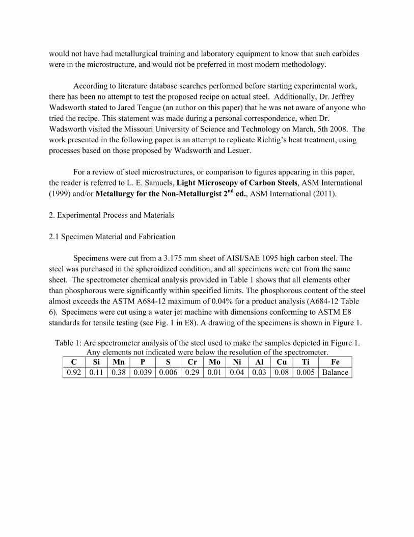
Specimens were cut from a 3.175 mm sheet of AISI/SAE 1095 high carbon steel. The steel was purchased in the spheroidized condition, and all specimens were cut from the same sheet. The spectrometer chemical analysis provided in Table 1 shows that all elements other than phosphorous were significantly within specified limits. The phosphorous content of the steel almost exceeds the ASTM A684-12 maximum of 0.04% for a product analysis (A684-12 Table 6). Specimens were cut using a water jet machine with dimensions conforming to ASTM E8 standards for tensile testing (see Fig. 1 in E8). A drawing of the specimens is shown in Figure 1.
Table 1: Arc spectrometer analysis of the steel used to make the samples depicted in Figure 1. Any elements not indicated were below the resolution of the spectrometer.
C Si Mn P S Cr Mo Ni Al Cu Ti Fe 0.92 0.11 0.38 0.039 0.006 0.29 0.01 0.04 0.03 0.08 0.005 Balance

Figure 1: Dimensions of the steel tensile specimens in millimeters. The specimens were flat
with a thickness of 3.175 mm. The specimens had a taper in the gage section towards the center as allowed by ASTM E8.
2.2 Heat Treatment of Specimens
Heat treatment of the specimens was performed in a double heat treatment furnace with dual digital temperature controls. The top furnace was outfitted with an argon purging system for the purpose of preventing excess surface oxidation of the specimens. Specimens were Austenitized in the top furnace, and then were then quickly transferred to the molten lead bath in the bottom furnace, which was set to a constant temperature. A similar method was used successfully by Desy, Brittain, and Gensamer, when studying Bainite formation4. Prior to heat-treating, a layer of lead-oxide was scraped off the top of the lead bath to prevent coating of the specimens with the oxide, which is a decent thermal insulator and would slow the cooling rate. A series of 15 tests were performed with most tests having a different Austenitizing temperature or time and lead bath temperatures (Table 2).

Table 2: Intended furnace temperatures and times that samples would spend in the furnaces.
Targets Austenitizing Lead Bath No. Temp. (°C) Time (min) Temp. (°C) Time (min) 1 760 30 350 30 2 815 30 350 30 3 815 60 350 30 4 815 30 350 30 5 760 60 350 30 6 760 30 350 30 7 760 30 450 30 8 760 30 450 30 9 760 20 350 30 10 775 30 350 30 11 790 30 350 30 12 800 30 350 30 13 760 30 400 30 14 800 30 400 30 15 900 120 350 30
2.3 Testing of Specimens
Tensile testing of specimens after cleaning was performed on an Instron 1000 HDX load
frame. The unit calculated strain by using displacement measurements from an extensometer (not strain gages). The extensometer was not left on the specimens until failure; therefore, some of the strain data near the end of the tests was not collected. To determine a value for total percent elongation at failure (%EL), marks on the gage section nominally 50mm apart were measured for length with calipers before and after testing. The lack of strain data for the entirety of tensile testing necessitated the operation of the frame in position control instead of strain rate control. Operation of the frame under position control will produce a non-constant strain rate in the specimens that decreases with time. The position change rate was set to 1.9 mm/min. With a starting extensometer length of 50 mm, the maximum strain rate was 0.0381 (mm/mm)/min, which is less than the ASTM E8 maximum of 0.5 (mm/mm)/min.
Hardness testing was performed with a LECO LR-300TD in accordance with ASTM
standard E18. Before testing, standards were checked to make sure that the machine was still in calibration. Rockwell B standards showed that the instrument was still in calibration. Rockwell C standards with hardness values either higher or lower than the heat treated samples showed that the instrument was reading 2.0 low. Hardness values reported have been adjusted to account
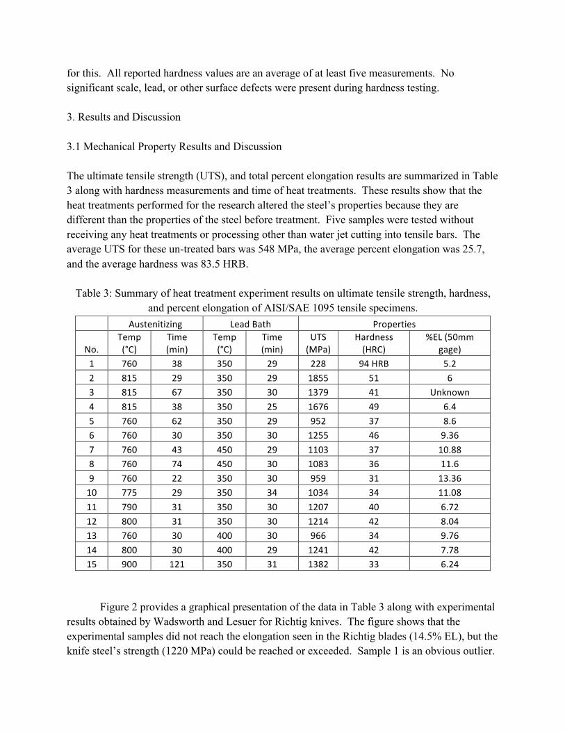
for this. All reported hardness values are an average of at least five measurements. No significant scale, lead, or other surface defects were present during hardness testing. 3. Results and Discussion 3.1 Mechanical Property Results and Discussion The ultimate tensile strength (UTS), and total percent elongation results are summarized in Table 3 along with hardness measurements and time of heat treatments. These results show that the heat treatments performed for the research altered the steel’s properties because they are different than the properties of the steel before treatment. Five samples were tested without receiving any heat treatments or processing other than water jet cutting into tensile bars. The average UTS for these un-treated bars was 548 MPa, the average percent elongation was 25.7, and the average hardness was 83.5 HRB.
Table 3: Summary of heat treatment experiment results on ultimate tensile strength, hardness, and percent elongation of AISI/SAE 1095 tensile specimens.
Austenitizing Lead Bath Properties
No. Temp (°C)
Time (min)
Temp (°C)
Time (min)
UTS (MPa)
Hardness (HRC)
%EL (50mm gage)
1 760 38 350 29 228 94 HRB 5.2 2 815 29 350 29 1855 51 6 3 815 67 350 30 1379 41 Unknown 4 815 38 350 25 1676 49 6.4 5 760 62 350 29 952 37 8.6 6 760 30 350 30 1255 46 9.36 7 760 43 450 29 1103 37 10.88 8 760 74 450 30 1083 36 11.6 9 760 22 350 30 959 31 13.36 10 775 29 350 34 1034 34 11.08 11 790 31 350 30 1207 40 6.72 12 800 31 350 30 1214 42 8.04 13 760 30 400 30 966 34 9.76 14 800 30 400 29 1241 42 7.78 15 900 121 350 31 1382 33 6.24
Figure 2 provides a graphical presentation of the data in Table 3 along with experimental results obtained by Wadsworth and Lesuer for Richtig knives. The figure shows that the experimental samples did not reach the elongation seen in the Richtig blades (14.5% EL), but the knife steel’s strength (1220 MPa) could be reached or exceeded. Sample 1 is an obvious outlier.

The oxide layer on the surface of the lead was not removed before submerging this sample, and the sample was coated with the oxide, which provided enough of a refractory layer so that the Austempering temperature was not achieved fast enough. The result was a microstructure with proeutectoid carbide along pearlite grain boundaries, which made the steel weak and brittle.
Figure 2: Experimental samples could be treated to obtain or exceed the strength of the Richtig knives, but not the elongation and not close to the combination of strength and elongation of the
knives. Sample numbers are shown for each data point followed by Austenitizing temperature(°C), time at temperature (min), then by lead bath temperature (°C) and time in lead
bath (min).
With regard to hardness, Wadsworth and Lesuer found significant variation in the two Richtig knives they studied. A large knife displayed hardness variations along the length between 36 and 46 HRC. The average was approximately 39 HRC. A smaller knife varied between 40 and 56 HRC with an average of approximately 50 HRC. Most of the samples in the present study (Table 3) possessed an average hardness that was within the range of the Richtig knives’ hardness. Frank Richtig likely polished his knives at least some before sale. The effect of surface preparation on the hardness has not been studied and is considered a future interest.
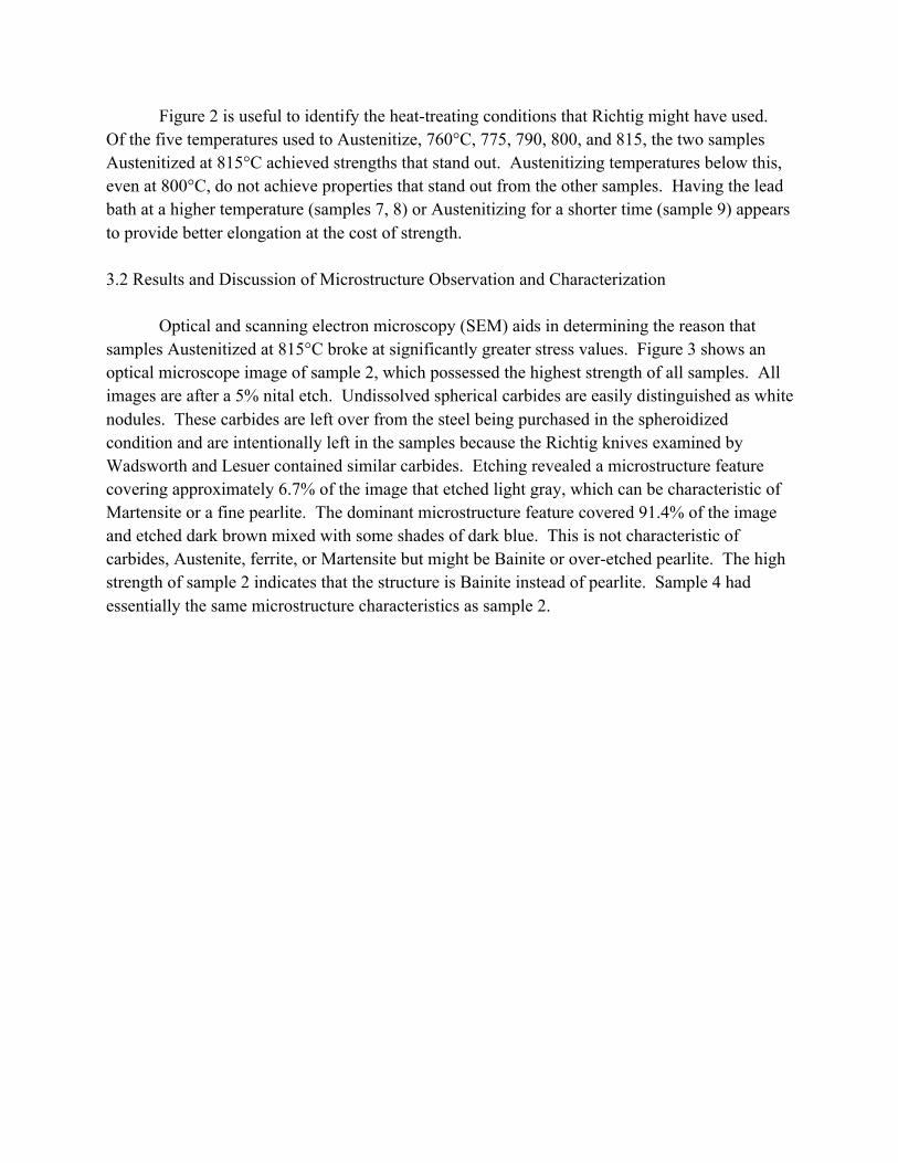
Figure 2 is useful to identify the heat-treating conditions that Richtig might have used. Of the five temperatures used to Austenitize, 760°C, 775, 790, 800, and 815, the two samples Austenitized at 815°C achieved strengths that stand out. Austenitizing temperatures below this, even at 800°C, do not achieve properties that stand out from the other samples. Having the lead bath at a higher temperature (samples 7, 8) or Austenitizing for a shorter time (sample 9) appears to provide better elongation at the cost of strength. 3.2 Results and Discussion of Microstructure Observation and Characterization
Optical and scanning electron microscopy (SEM) aids in determining the reason that
samples Austenitized at 815°C broke at significantly greater stress values. Figure 3 shows an optical microscope image of sample 2, which possessed the highest strength of all samples. All images are after a 5% nital etch. Undissolved spherical carbides are easily distinguished as white nodules. These carbides are left over from the steel being purchased in the spheroidized condition and are intentionally left in the samples because the Richtig knives examined by Wadsworth and Lesuer contained similar carbides. Etching revealed a microstructure feature covering approximately 6.7% of the image that etched light gray, which can be characteristic of Martensite or a fine pearlite. The dominant microstructure feature covered 91.4% of the image and etched dark brown mixed with some shades of dark blue. This is not characteristic of carbides, Austenite, ferrite, or Martensite but might be Bainite or over-etched pearlite. The high strength of sample 2 indicates that the structure is Bainite instead of pearlite. Sample 4 had essentially the same microstructure characteristics as sample 2.

Figure 3: Characteristic image of sample 2 at 1,000X. Carbides that were not dissolved during
Austenitization appear white. Two other microstructure features are distinguishable; the dominant one etched dark brown mixed with some shades of dark blue and the other a light gray. SEM examinations were used in a further attempt to identify the dark-etched, dominant microstructure feature. Figure 4 shows a characteristic image of sample 2 at two-thousand five-hundred times magnification (2,500X). The structure had an appearance difficult to describe but will be referred to as “jagged” containing thin, short alternating plates arranged internally into patterns. This structure is not characteristic of pearlite. Essentially through process of elimination, the dominant microstructure feature of sample 2 is Bainite.

Figure 4: Scanning electron microscope image of sample 2 showing the appearance of the
dominant microstructure observed in Figure 3. The structure is not consistent with pearlite, Austenite, free ferrite, or Martensite. (2,500X)
Optical and SEM examination of sample 9 shows a clear presence of pearlite in the microstructure (see Figures 5, 6). A representative SEM image at 2,500X, provided as Figure 6, shows that the dominant microstructure feature of sample 9 is pearlite. Spherical carbides left over from the spheroidized condition are also present. Gray regions in Figure 5 are potentially pearlite with plate thicknesses small enough to not be distinguished at 1,000X and/or where the etching did not significantly distinguish the ferrite from cementite. Figure 5 also shows a phase colored white after etching. Considering colors alone with a 5% nital etch, the white phase could be carbide, ferrite, or Austenite. Without the presence of Austenite stabilizing alloys (e.g. nickel) or at least carbon trapped in solid solution by a Martensite-forming quench, it is extremely unlikely that the phase is Austenite. The shape of the white-etched phase under consideration is not consistent with carbides and is most likely proeutectoid ferrite. Typically, proeutectoid ferrite should only form in plain carbon steels with carbon contents of less than 0.76%; therefore, an explanation is needed. Although the overall steel should have approximately 0.95% carbon content, the matrix could be of a hypoeutectoid composition if not enough of the spherical carbides were dissolved during Austenitizing. This is a potential explanation for the presence of proeutectoid ferrite. The explanation is made more reasonable by considering that sample 9 was treated at the lowest Austenitizing temperature used (760°C) for the least time (22 minutes), which would allow for the least opportunity to dissolve carbides.

Figure 5: Optical microstructure image of sample 9 at 1,000X showing pearlite, spherical
carbides, and a white phase not explicitly identified with optical observations. The phase was determined to be ferrite because undissolved carbides made the matrix hypoeutectoid. No region
appears to be like the lower Bainite in sample 2 that is shown in Figure 3.
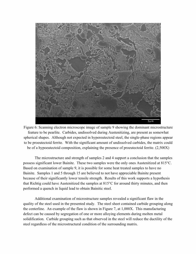
Figure 6: Scanning electron microscope image of sample 9 showing the dominant microstructure
feature to be pearlite. Carbides, undissolved during Austenitizing, are present as somewhat spherical shapes. Although not expected in hypereutectoid steel, the single-phase regions appear to be proeutectoid ferrite. With the significant amount of undissolved carbides, the matrix could
be of a hypoeutectoid composition, explaining the presence of proeutectoid ferrite. (2,500X) The microstructure and strength of samples 2 and 4 support a conclusion that the samples possess significant lower Bainite. These two samples were the only ones Austenitized at 815°C. Based on examination of sample 9, it is possible for some heat treated samples to have no Bainite. Samples 1 and 5 through 15 are believed to not have appreciable Bainite present because of their significantly lower tensile strength. Results of this work supports a hypothesis that Richtig could have Austenitized the samples at 815°C for around thirty minutes, and then performed a quench in liquid lead to obtain Bainitic steel. Additional examination of microstructure samples revealed a significant flaw in the quality of the steel used in the presented study. The steel sheet contained carbide grouping along the centerline. An example of the flaw is shown in Figure 7, at 1,000X. This manufacturing defect can be caused by segregation of one or more alloying elements during molten metal solidification. Carbide grouping such as that observed in the steel will reduce the ductility of the steel regardless of the microstructural condition of the surrounding matrix.

Figure 7: Carbide grouping along center of plate steel. Bands of carbides, such as these in the steel, reduce ductility. Image at 1,000X. Note that the thickness of the plate runs from left to
right with respect to the image. 4. Conclusions
Undergraduate students were successfully incorporated into a research project using
funding from a grant internal to their university. Students were exposed to metallographic techniques and electron microscopy. Additionally, students were guided through contributing to experimental procedures and literature review.
Experiments based on the work of Wadsworth and Lesuer, were conducted in an attempt
to replicate the heat treatment process used by Frank Richtig to make knives in the early 20th century. The results of the tests show the following:
I. Bainite can be generated in AISI/SAE 1095 steel by Austenitizing at 815°C for 30 minutes followed by submersion in molten lead at 350°C for 30 minutes. II. While apparently possible for Richtig to make Bainite before Bainite was even named, the process presented in this paper does not achieve the combination of strength and ductility of the

Richtig knives. This failure is likely due to processing defects during the manufacture of the steel purchased for the study. III. The heat treatments studied in this work were able to produce Rockwell C hardness values within the range of hardness values of Richtig knives. 5. Future Work
The authors intend to redo the study using higher quality steel. Additionally, the effect
on hardness of fine polishing of the steel after heat-treating should be investigated. Fine polishing is of interest because a knife maker would polish a knife after making it. A thin layer of decarburized steel might be removed, or reduced by polishing. Finally, at the end of the work, the authors are interested in a practicing knife maker/blacksmith attempting to replicate a Richtig knife.
6. Acknowledgments Jason Benne and Phillip Thompson for sample preparation, testing assistance, and writing procedures for students to prepare metallography samples. The authors thank the Dean and Department Chairs of the College of Engineering and Natural Sciences at UT Martin for awarding the funding needed for the project. The authors express appreciation for the Blankenship Undergraduate Research Endowment for providing the funding needed for the project. Thanks to Weston Gentry and Craig Ingram at the UTM Instructional Technology Center for assisting the authors with image formatting and resolution requirements. 7. References 1. Lambert, Glen. F.J. Richtig: Believe It or Not Cutler. Annual Edition Knives ’84; 1984. p. 40-4 2. J. Wadsworth and D. Lesuer. The knives of Frank J. Richtig as featured in Ripley's Believe It or Not!. Materials Characterization. 2000; 45: 315-26 3. E. S. Davenport and E. C. Bain, “Transformation of Austenite at Constant Subcritical Temperatures,” Trans AIME. 1930; 90: 117-54 4. Donald H. Desy, J. O. Brittain, and M. Gensamer. (National Advisory Committee for Aeronautics) Strength and Ductility of Bainitic Steels. Technical Note 3989. Columbia University, New York, New York; 1957