Embed Size (px)
Citation preview

1
University of Tartu
Faculty of Science and Technology
Institute of Technology
Miroslav Rolko
UNIVERSAL ANTENNA ROTATOR CONTROLLER FOR SATELLITE
GROUND STATIONS Bachelor’s Thesis (12 ECTS)
Computer Engineering Curriculum
Supervisor(s):
Indrek Sünter
Viljo Allik
Permission for defense:
Supervisor(s): …………………………………………
/ Signature, date /
Tartu 2016

2
Resümee/Abstract
Universaalne pööraja kontroller satelliidi jaamade jaoks
Käesolev lõputöö kirjeldab alalisvoolu mootoritega pöörajatele juhtmooduli arendamise
protsessi. Arendamise protsess koosneb neljast kronoloogilisest sammust:
1. Esimene osa keskendub projekti tehnilistele nõuetele.
2. Teine osa uurib iga liidest ja kirjeldab selle funktsionaalsust.
3. Kolmas osa pühendub trükkplaatide monteerimisele ja korpuse ehitamisele.
4. Viimane osa kirjeldab universaalse pööraja kontrolleri püsivara programmeerimist.
CERCS: T120 Süsteemitehnoloogia, arvutitehnoloogia, T125 Automatiseerimine, robootika,
control engineering, T170 Elektroonika, T190 Elektrotehnika
Marksõnad: kontroller, asimuut, kõrgusnurk, mootor, kodeerija, tarkvara, satelliit
Universal antenna rotator controller for satellite ground stations
This dissertation describes the process of designing simple printed circuit board (PCB),
assembly of components and creating a firmware for turning motors with direct current.
Development of the universal antenna rotator controller consists of four chronological steps in
thesis:
1. The first part is focusing on requirements of the new project.
2. The second part is investigating each interface of the circuit and explains its
functionality.
3. The third part is dedicated to assembling of the printed circuit board and building of an
enclosure.
4. The last part is writing a firmware for the universal rotator controller (URC).
CERCS: T120 Systems engineering, computer technology, T125 Automation, robotics,
control engineering, T170 Electronics, T190 Electrical engineering
Keywords: controller, azimuth, elevation, motor, encoder, software, satellite

3
Contents
Resümee/Abstract ....................................................................................................................... 2
Terms and abbreviations ............................................................................................................ 5
1. Introduction ............................................................................................................................ 7
2. Controller requirements, design and installation .................................................................... 9
2.1 Requirements for turntable rotator controller in RF anechoic chamber ........................... 9
2.1.1 Size requirement ........................................................................................................ 9
2.1.2 Microcontroller .......................................................................................................... 9
2.1.3 Safety features ........................................................................................................... 9
2.1.4 Measurements and output .......................................................................................... 9
2.1.5 Memory ..................................................................................................................... 9
2.1.6 Rotation ..................................................................................................................... 9
2.1.7 Communication ......................................................................................................... 9
2.1.8 Power ....................................................................................................................... 10
2.1.9 Error reporting ......................................................................................................... 10
2.2 Requirements for URC for satellite ground station ........................................................ 11
2.2.1 Rotation axis support ............................................................................................... 11
2.2.2 Antenna position indication and display ................................................................. 11
2.2.3 Size requirement ...................................................................................................... 11
2.2.4 Communication and control .................................................................................... 11
2.2.6 Power ....................................................................................................................... 12
2.2.7 Debugging ............................................................................................................... 12
2.3 Design ............................................................................................................................. 12
2.3.1 Components selection ............................................................................................. 12
2.3.2 Simple block diagram for TRC ............................................................................... 12
2.3.3 Simple block diagram for URC ............................................................................... 13
2.3.4 Schematic design ..................................................................................................... 14
2.3.5 Development of the board and selecting components TRC in RF anechoic chamber
.......................................................................................................................................... 14
2.3.6 Development of the board and selecting components for rotator controller for
satellite ground station. .................................................................................................... 19
2.3.7 Design of the printed circuit board layout (PCB) ................................................... 27
2.4 Assembly and installation .............................................................................................. 28
2.4.1 Components for assembly ....................................................................................... 28
2.4.2 Connection schematics ............................................................................................ 29
2.4.3 Protection elements of the circuit ............................................................................ 31
3. Embedded software diagram ................................................................................................ 32
3.1. Software diagram .......................................................................................................... 32

4
4. Potential improvements ........................................................................................................ 33
5. Applications ......................................................................................................................... 33
6. Conclusion ............................................................................................................................ 33
7. Acknowledgements .............................................................................................................. 33
8. Kokkuvõte ............................................................................................................................ 34
Appendices ............................................................................................................................... 37
Appendix A TRC diagram and PCB boards ........................................................................ 37
Appendix B URC diagram and PCB boards design ............................................................. 39
Appendix C URC prototype photos ..................................................................................... 41
Appendix D BOM ................................................................................................................ 43
Appendix E Motor driver board sample code ...................................................................... 45
Authorization ........................................................................................................................ 48

5
Terms and abbreviations AC Alternating current
ADC Analog-to-digital converter
AGC Automotive glass cartridge
AMP Amplifier
ARM Advanced RISC machine
CCW Counterclockwise
CMOS Complementary metal–oxide–semiconductor
COM-port (communication port) Serial port interface
CS Current sense
CTS Clear to send
CW Clockwise
DAC Digital-to-analog converter
DC Direct current
EU European Union
FET Field effect transistor
F-RAM Ferroelectric random access memory
GPIO General purpose input / output
HEXFET Hexagonal shape field effect transistor
I2C Inter-integrated circuit
IR Infra-red receiver
IRS Interrupt service routine
JTAG Joint Test Action Group
LCD Liquid crystal display
LED Light emitting diode
LEO Low-Earth orbit
LQFP Low profile quad flat pack

6
LS , HS High side, low side
MCU Microcontroller unit
MOSFET Metal–oxide–semiconductor field-effect
transistor
OSC Crystal oscillator
PCB Printed circuit board
Potentiometer Three-thermal resistor
PuTTY Open-source terminal emulator, serial console
and network file transfer application
PWM Pulse width modulation
ROM Read-only memory
RS-232 Standard for serial communication
RTS Request to send
SDA Serial data line
SDC Serial data clock
TRC Turntable universal controller
TTL Transistor-transistor logic
UART Universal asynchronous receiver/transmitter
USB Universal serial bus
URC Universal rotator controller

7
1. Introduction
New satellite ground stations are constantly being developed and built for new CubeSat
projects as the requirements for data rates and signal quality is increasing. This new trend
moves towards increased bandwidth and the need for higher pointing accuracy with higher
frequencies.
Recently, several universities have launched CubeSat projects. University of Tartu has
successfully completed the ESTCube -1. ESTCube-1 mission was launched on 7th of May,
2013 and ended in 17th of Feb, 2015. ESTCube team is currently working on further
CubeSats ESTCube-2 (at the time of writing, the approximate launch window was planned in
2018) and ESTCube-3.
ESTCube-1 is orbiting at an altitude of 650 km with proximately speed of 7,76 km/s and
inclination of 98º. During a 24-hour period in Estonia, there are eleven communication passes
with ESTCube-1. The average pass enables a communication for about 9-10 minutes [1].
In order to establish a good communication between the satellites and earth, proper satellite
ground station must be built. As CubeSat missions are usually low on mass, volume and
power, satellite ground stations need more amplification for the received signal and more
power for transmission. Common solution for CubeSat project is build a custom satellite
ground station as it is more cost effective. Turning the antenna into precise position is crucial,
if high quality communication with CubeSat has to be achieved, since the antenna
performance is very sensitive against pointing errors.
This bachelor thesis project has been performed at the Space Technology Department of Tartu
Observatory.
Tartu Observatory satellite ground station has installed Yagi antenna array, which has full 180
degrees elevation and about 400 degrees azimuth range. The antenna consists of four 70 cm
band cross-yagi antennas (M2-436CP42UG) yielding a gain of 22 dBi and two 2 m band
cross-yagi antennas (M2-2MCP22), all mounted on fiberglass poles. Signals from the same
band antennas are added with off the shelf power dividers. In our project, the antennas are to
be rotated with two motors, MT-3000AEL for azimuth and OR2800PX for elevation.
Communications with ESTCube-1 relied on satellite ground stations that had custom-built
rotator controllers. The controller did not support the remote calibration of antenna direction
and had a cumulative error in azimuth and elevation readings. As a result, it was proposed to
design a new controller module.
Result of this project can be also used to control any antenna system with similar properties.

8
The objectives of this thesis are as followed:
Gather requirements for rotator controller design
Select components, design schematics and PCB layout for the rotator controller
Assemble the PCB
Design an enclosure for the rotator controller and assemble the module
Test the rotator controller in multiple settings
A more detailed list of requirements is provided in section 2.1.

9
2. Controller requirements, design and installation The development of (URC) for antenna and turntable rotator controller (TRC) is divided into
three main sections:
requirements
design
assembly and installation
2.1 Requirements for turntable rotator controller in RF anechoic
chamber
2.1.1 Size requirement The size of the box, where printed circuit board (PCB) will be mounted, is 300x250x150mm
and size of the PCB will be 90x90 mm.
2.1.2 Microcontroller Microcontroller shall be from Advanced RISC Machine (ARM) family, STM32 Cortex-M4
series with 64 pins.
2.1.3 Safety features Design must be compliant to applicable safety electromagnetic compatibility regulation and
protection against short-circuit and eventual overloads has also to be implemented.
2.1.4 Measurements and output The external sensor, which is attached to the motor, will capture 10 impulses per 1 degree
angle. The result shall be readable via serial port with 0.1 degree resolution.
2.1.5 Memory The TRC position shall be saved in external nonvolatile memory (FRAM). At system, power-
up the actual turntable position shall be restored from nonvolatile memory.
One possible option was to use a battery powered backup RAM in STM32, but it would have
been less reliable and probably a more expensive solution than the application of an external
FRAM.
2.1.6 Rotation Motor is capable of turning both clockwise (CW) and counterclockwise (CCW) proximately
at an angular rate of 360 degrees per minute (Minimum voltage has to be applied to release an
electromagnetic brake; otherwise motor will not start any rotation).
2.1.7 Communication Communication between TRC and computer has to be established via serial port RS-232
through UART protocol. The UART1 will be used for PC communication and UART2 for
possible debugging, if needed. Command sets should be based on a four character ASCII
command separated parameters by comma.

10
List of the commands shall be as followed:
Command Explanation of command
"VERS" Print out version of the firmware
"HELP" Print out all implemented commands
"BAUD" Set up a baud rate for RS-232 serial port
"ECHO" Print current command echo state
"GOAZ" Set an azimuth value to turn the motor to
"RDAZ" Print current position in degrees
"WRAZ" Write motor current position in degrees
"RDAP" Print the state of the position pulse counter
"HALT" Emergency stop of motor
"OVRA" Setup azimuth and elevation mechanical inertia for position
accuracy
Figure 1: Table of command for TRC
2.1.8 Power The rotator controller should have a toggle power switch to power it on or off. The TRC
should be connected to 27 V supply, as the motor is supplied with 27 Volts at 2.25 Watts (W).
2.1.9 Error reporting Indication of system errors should be reported via light emitting diode (LED) and via RS-232
serial port.

11
2.2 Requirements for URC for satellite ground station
All requirements that applied to the turning table, also apply to the satellite ground station URC, with
the following additional requirements:
2.2.1 Rotation axis support URC should be able to rotate the antenna system in azimuth and elevation axis.
2.2.2 Antenna position indication and display Both antennas, azimuth and elevation shall be calculated and shown on the LCD via inter-
integrated circuit (I2C) and via serial port for the purpose of remote control. The values have
to be displayed in format xxx.x with 0.1 degree resolution.
2.2.3 Size requirement URC can also be used as a general purpose rotator controller and supposed to have good
portability for easy installation and access. The maximum size of the enclosure of the antenna
controller is approximately 300x250x150 mm and the size of the controller PCB shall be less
or equal to 100 x100 mm.
2.2.4 Communication and control List of the commands will be as followed:
Command Explanation of command
"GOAZ", "GOEL" Set an azimuth or elevation value to turn the motor to
"GOAE" Set an azimuth and elevation value to turn the motor to
"RDAZ" Print current position of azimuth in degrees
"RDEL" Print current position of elevation in degrees
"WRAZ" Write a motor current position of azimuth in degrees
"WREL" Write a motor current position of elevation in degrees
"RDAP", "RDEP" Print amount of impulses for azimuth or for elevation
"OVRA" , "OVRE" Setup azimuth or elevation mechanical inertia for
position accuracy
"HALT", "HLTA",
"HLTE"
Stop both motors, stop azimuth motor, stop elevation
motor
"LCDC" Set up contract for LCD display
Figure 2: Table of command for URC
The URC should implement manual control of the antenna direction by using push-buttons or
switches or using infrared remote control from range of at least 5 meters from the controller
location.

12
2.2.6 Power The external supply voltage of the URC shall be single phase 230 V AC mains voltage.
The supply voltage to the rotator DC motors shall be 24… 32 V DC at 2 A DC current.
2.2.7 Debugging Additionally, an ARM Joint Test Action Group (JTAG) maybe be is implemented as optional
feature for debugging.
2.3 Design
2.3.1 Components selection Most of the components were ordered from Farnell [2] and some of the components (which
were out of stock) from the Mouser Electronics [3]. Passive components were already stocked
at the electronics laboratory in Tartu Observatory.
2.3.2 Simple block diagram for TRC
Figure 3: Simple diagram TRC

13
2.3.3 Simple block diagram for URC
Figure 4: Simple diagram URC

14
2.3.4 Schematic design For schematics and PCB layout design, DesignSpark PCB 6.1 was recommended by our lead
engineer. DesignSpark is a free of charge PCB layout drawing environment [4].
2.3.5 Development of the board and selecting components TRC in RF
anechoic chamber
2.3.5.1 Power supply and schematics
A power supply system 19” AC/DC linear regulators with very low interference optimized for
medical and science applications had been chosen.
Voltage Current Power Dimension Model name
24V 2.5A 60W 180x100x130mm PSG 124 13105-014
The power supply is suitable for our application as the hardware will be installed next to RF
anechoic chamber [5].
Figure 5: Power supply schematics
Power supply of 24 V and 2.5 A is connected to circuit board. First passive component
capacitor F050VDC02A is used as a low pass filter or alternatively called feed-through
capacitor. Then the voltage flow continues into three following sections:
The 24 V supplies the IRF4905 HEXFET, which is used to drive the motor. With the
help of LM7812, a down-conversion from 24 V to 12 V is performed. As standard
solution, two 10 µF capacitors are added for lowering impedance and one ferrite to
filter out potential high frequency noise.
The 12 V supplies the incremental encoder’s interfaces and then the supply is down-
converted via regulator LT1129 IQ to further 3.3 V. Two capacitors of 1µF and one
ferrite have been added for the same purpose as mentioned earlier.
The 3.3 V supplies the control electronics like microcontroller, FRAM or LEDS.

15
2.3.5.2 Microcontroller for TRC
For main component of building the TRC the ARM microcontroller (MCU) had to be chosen,
partly because it is the preferred chip set of the ESTCube team and secondly it is predefine via
requirements the project.
The microcontroller is offering enough pins for solving our design requirements as followed:
Transmit and receive data between computer and microcontroller should be solved via
UART communication port. The transmit data pin (TxD) and receive data pin (RxD)
are required for UART1 and UART2. UART1 will be used as the main
communication between the electronic board and PC.
MCU has two Inter-Integrated circuits (I2C bus) for exchanging data with
FRAM.
MCU has two pins for a high speed crystal oscillator. The oscillator should provide the
MCU with a frequency of 8 MHz
MCU has a four different incremental encoder interfaces (16 or 32 bit resolution).
Enough pins for LEDs, controlling transistors circuit and optional output for Serial
Peripheral interface (SPI).
On above mentioned features STM32F401RET6 32 bit microcontroller was selected as it is
fulfilling all requirements for the circuit [6].
Model name Architecture RAM Number of
Pins
CPU speed
STM32F401RET6 ARM Cortex-M4 96KB 64 84MHz
2.3.5.3 TRC motor driver circuit schematics
Figure 6: TRC schematics

16
The fifth generations IRF4905 HEXFET P-Channel are implemented in the circuit. IRF4905
has very fast switching properties. This high power MOSFET is enough efficient and reliable
for our application. In our schematics MOSFET (IRF4905S) P-Channel is installed with
combination of the FDV303N Digital FET, N-channel.
The digital FET, N-channel is making the gate of the switching MOSFET (IRF4905S)
negative compared to the source via pulling the voltage level down. When an N-channel is
open, current is flowing through a resistor (R10, R11). At the moment when the gates V4 or
V5 gets more negative than the source, V4 respectively V5 drain will open and the current
starts to flow.
2.3.5.4 Incremental encoder interface
Figure 7: TRC incremental encoder interface schematics
Incremental encoder consists of 5 kΩ potentiometer 938 GA (voltage divider), and low pass
filters. Zener 24V diode is protecting the MCU against higher voltage. The motor is
producing a rotation of 360 degrees by 3600 impulses, which correspond to exactly 10
impulses per 1 degree.
2.3.5.4.1 Potentiometer settings
𝑉𝑜𝑢𝑡 = (R2
R1+R2)* 𝑉𝑖𝑛 3.3 V = (
1 kΩ
3 kΩ+1 kΩ)* 12 V
Potentiometer R2 shall be set on 3 kΩ.
2.3.5.4.2 Low pass filter
𝑓𝑐 = 1
2𝜋𝑅𝐶 𝑓𝑐 = (1
2𝜋∗4000∗3300∗10−12)
𝑓𝑐 = 12057.1926585 HZ
[7]

17
2.3.5.5 Serial communication port
Figure 8: RS-232 driver schematics
Communication between PC and URC is established by serial port RS-232 through UART
protocol. The control of the board requires downloading free open-source terminal emulator
PuTTY [8]. Serial port option is selected in PuTTy software and serial port channel gets
connected. The controlling of URC is performed in command window via four-character-
commands by the user.
The UART interface consists of block of circuit responsible for sending and receiving a
sequence of bits. It is a protocol where level of the voltage represents individual bits. Those
bits are transferred to RS-232 line driver. Serial standard RS-232 is transmitting data to the
computer via USB serial adapter converter.
ADM3202 chip standard solution for RS-232 has been provided by Tõravere laboratory. The
chip has 16 pins of which eight are reserved for data transmission (TxD) and reception(RxD)
lines. Rest eight pins are used for decoupling and inverting voltage.
RS-232 has negative and positive voltage level in our project ±6.6V. The negative voltage
level is called ‘mark’ and has logical value (1) and the positive voltage is called a ‘space’ has
logical value (0) [9].
In order to establish serial connection between PC and UART, six parameters have to be
configured:
1. Setup of baud rate is 115200 bit/s
2. Setup for number of data bits is 8 bit
3. No parity is set.
4. Number of stop bits is 1
5. Full duplex mode is selected
6. No hardware flow control

18
For the moment two UARTs are initialized, UART1 is for command line and UART2 is for
indicating errors. Therefore while UART is initialized, additional seventh parameter has to be
selected: UART1 or UART2.
Each UART is using one interrupt vector which supports several interrupt causes. Only two of
them are used by the driver software: "Rx buffer not empty" and "TX buffer empty".
[10] [11]
2.3.5.6 Ferroelectric Random access memory (FRAM)
Figure 9: FRAM schematics
External non-volatile memory is required, as MCU internal RAM will be erased after power is
disconnected. In this situation, an absolute position of the table is not stored. But in our
project we need to update the current position every time motor turns. To save the actual
antenna position after eventual power loss an external non-volatile memory is needed. MCU
internal flash memory can also be used but it has a too limited number of erase/write cycles
available to ensure reliable operation of the controller.
For this purpose FM24CL16B was chosen, which is using Inter-Integrated Circuit (I2C).
2.3.5.6.1 I2C
I2C is one of the most used buses - a serial protocol for two-wire interface to connect devices
like microcontrollers, input/output interfaces and other peripherals.
Hardware level: I2C is bus is using two signals - SCL clock signal and SDA data signal. The
clock is generated by master device. If some slave has own internal clock and master is
sending more data, then it result in clock stretching.
I2C bus drivers are two bidirectional open-drains, where devices are pulling signal line low.
To get the high line signal at suitable level, a pull-up resistor is added to the circuit. Also it
prevents a damage of the driver or excessive power dissipation. In our project a 3.3 V level of
voltage and 3.3 kΩ pull-up resistors are applied. To improve the noise performance, a 1uF
capacitor is connected between supply voltage and ground pin on each i2C device. [12]

19
2.3.6 Development of the board and selecting components for rotator
controller for satellite ground station.
2.3.6.1 Power supply and schematics Power supply for satellite ground station is almost identical as for the previous rotator. The
manufacturer is Schroff and it is a little more powerful model [13].
Voltage Current Power Dimension Model name
24V 3.5A 84W 180x100x130mm PGG 124
The power supply is suitable for turning two separate motors for elevation and azimuth.
All components and schematics are the identical as for TRC. To the circuit only one fuse (SR-
5 T3, 15A 250V DIP) was added between the F050VDC02A and 24V terminal; for better
protection of the circuit.
2.3.6.2 Microcontroller for URC
All requirements choosing MCU that applied to the TRC, also apply to the URC for the
satellite ground station, with the following exceptions:
More pins are needed, as board has more functionality, suitable is 100 pins.
More cpu speed is needed, as the board is for universal purposes, preferably 168 MHz
The URC also requires bigger programming and internal memory, because its task will
be to measure two DC motors.
For URC, theSTM32F407VGT6TR 32 Bit microcontroller had been chosen [14] .
Model name Architecture RAM Number
of Pins
CPU speed
STM32F407VGT6TR ARM Cortex-M4 192KB 100 168MHz
.

20
2.3.6.3 Internal driver schematics
Figure 10: Internal driver schematics
The internal rotator schematics consist of two quad channel high side drivers (VNQ-810).
Every chip has eight inputs and four outputs. The outputs are following OUT1, OUT2,
BRAKE, and LED. First four inputs are for general purpose and next four inputs are status
ports. Status ports can be used for error indication or if they are configured as inputs, for error
detection e.g. detecting external overcurrent or over temperature sensor signal.
Command Explanation of command
OUT1 output for clockwise(CW)
OUT2 output for counter clockwise(CCW)
BRAKE output for braking a motor
LED output for optional use
Figure 11: Internal rotator outputs table

21
Every chip has four separate N-channels MOSFETS, drivers, voltage clamp, temperature
sensor and current limiter. The application is operating on two regimes: with 12V and by
actual original source voltage, so in our case 24V (operating maximum level is 36V) by two
separate terminals.
The activation of the transistor proceeds by sending a signal of 3.3 V into input of the driver
via MCU pin. That will open the drain of the MOSFET inside of VNQ-810 for the current to
flow and motor starts to rotate in suitable direction For some applications one chip would be
sufficient enough to operate two motors, but only if the motor current consumption is low
enough to not overload the chip.
These drivers were implemented to the PCB layout for general purposes and for every kind of
other possible application, but they are not suitable for turning antenna, as those driver-chips
are not capable of reversing the voltage. Additionally, they are not too efficient. One
alternative would be to implement two relays to the circuit, but it would make the installation
and assembly of device more complicated. Therefore we decided to make an external board
with other drivers to keep it simpler [15].
2.3.6.4 External driver schematics
Figure 12: External driver schematics

22
2.3.6.4.1 Drivers settings
For our application, we have created external motor driver board which includes two full
bridge motor drivers (VHN5019A-E). These allow us to reverse the voltage, which was
fulfilling our requirement for antenna rotators (MT-3000-AEL) for azimuth and (OR2800PX)
for elevation. Both motors have only four input cables - two cables for the voltage source
(S1+/-24V) for motors and two cables for an external sensor (S2+12V) for reading impulses.
Every motor driver chip consists of four N-channel-Powers MOSFET. They are divided to the
two blocks of pair transistors. On the left side HSA, LSA on the right side and HSB, LSB. Left
block of the driver gets activated via DIAGA /ENA (logical ‘1’), and right block of the driver
gets activated via DIAGB /ENB (logical ‘1’).
In case MOSFET HSA and LSB transistors are opened (logical ‘1’), current is flowing through
HSA, LSB in diagonal and turning the motor in CW direction for azimuth or up direction for
elevation.
In case MOSFET HSB and LSA transistors are opened (logical ‘1’), current is flowing through
HSB, LSA in diagonal and turning the motor in CCW direction for azimuth or down direction
for elevation.
In both cases pulse wide modulation (PWM) must be in switch on or has to be as constant
(logical ‘1’). [16].
Following truth table describing all operating conditions:
INA INB DIAGA/ENA DIAGB/ENB OUTA OUTB CS Op. Mode
1 1 1 1 H H High imp. Brake VCC
1 0 1 1 H L ISENSE=IOUT/K CW
0 1 1 1 L H ISENSE=IOUT/K CCW
0 0 1 1 L L High imp. Brake GND
Figure 12: External driver settings
2.3.6.4.2 ADC settings
The output of current sense pin. This output delivers a current proportional to the motor
current, if CS_DIS is low or left open. The information can be read back via MCU pin as an
analog voltage across and external resistor [17].
2.3.6.5 Incremental encoder interface with three channels

23
Figure 13: URC Incremental encoder interface schematics All components and schematics are the identical as for TRC; the only difference is a multi-capture of
signal instead of single-capture. The reason this is that schematics becoming more universal and we
can observe CW and CCW signal separately. We also added double pins for optional resolution of 16-
bit or 32-bit capture for various applications. As the excessive amounts of impulses are sent by the motor, it is comfortable to use 32-bit channel.
Unfortunately, if this option is selected, then MCU will exclude one DAC pin (PA5), which is used to
control speed of motor rotation. Choice has to be made, if both DAC ports are implemented then only
one incremental encoder interfaces of 32-bit can be used or vice versa. To recognize CW and CCW turning direction of the motor, the incremental encoder interface should
capture both signals separately by Track A and B. The idea is that rising and dropping signal edges are
shifted by period generated via timers (each timer has different clock). Therefore Track A and B with rising or falling edge are never same. Thus, we can observe on the
Track A the rising or falling edge and on Track B low- or high-level signal. This way we manage to
determine the CW and the CCW signal. Also Track N was implemented to measure one complete cycle of rotation (360°).

24
Figure 14: Incremental encoder interface clocks. [18]
2.3.6.6 Liquid crystal display and schematics
For the URC a display (MIDAS MCCOG22005A6W-BNMLWI) was selected [19].
The display supports white alphanumeric characters 20 x 2 on blue background and operates
in 3V to 5V in logic voltage. It has also an Inter-integrated circuit (I2C) feature to meet
hardware requirements. I2C interface bus is described in section 2.3.5.6.1
Figure 14: LCD interface schematics
For the LCD display we have designed a small external PCB layout for easier installation and
attaching of display to the front panel. On external board are also placed two pull up resistors
(3.3kΩ) and two capacitors (1µF) for booster circuit, as placing those passive components at
the end of the line is improving signals at LCD terminal.

25
2.3.6.7 Speed control interface
Figure 14: Speed interface schematics
The chosen MCU has digital analog converter (DAC) pin outputs PA4 and PA5, which can
control non-inverting operational amplifiers to intermediate the voltages in the range of
0….10V.
For this purpose are installed LMC6482 CMOS [20] dual rail-to-rail input and output
operational amplifier with power supply of 12V. The operating amplifiers have good
properties for protecting the circuit against eventual voltage or current spikes, which occur
from the motor drivers or cables. Resistors R23, R24, R26 and R27 are optional to lower
impedance for the case when firmware leaves GPIO pin in high state.
2.3.6.7.1 Voltage gain
A𝑣 =𝑉𝑜𝑢𝑡
𝑉𝑖𝑛= 1 +
𝑅𝐹
𝑅2
A𝑣 =10𝑉
3.3𝑉= 1 +
4.7 kΩ
2 kΩ= 3.35 𝑥
[21]

26
2.3.6.8 User interface schematics
Figure 15: User interface schematics
As second option to control URC are sets of buttons. For the moment we intended to connect
only four buttons covering left and right axis for azimuth and up and down axis for elevation
and kept the fifth button optionally to use as a reset button or for other alternative functions.
For each set of rotation we installed one separate toggle switch on the front panel. Pressing
the switch left or right we configured for the azimuth respectively up and down for the
elevation. Capacitors (10 ηF) were added for filtering the noise while pressing the button and
pull-up 4.7 kΩ resistors to define high or low state of the pin.
2.3.6.8.1 Floating
MCU will not recognize high or low state of the pin if there is nothing connected to the pin.
This unknown state is being called "floating". To distinguish high or low state, pull-up or
down resistors are added to the circuit. Pull-up resistors are pulling the current into MCU or to
the ground via switching the button on or off. The current will not be pulled into MCU pin
because of the high impedance - the internal resistor of the MCU will push current away to
the ground if button is pressed.
2.3.6.8.2 High and low state of the pin
Each button has separate power supply voltage of 3.3V and pull-up 4.7 kΩ resistors. Buttons
have two following states:
High state - input pin indicate high state when the button is not pressed. The pin is not
connected to the ground and small amount of current is flowing between resistor and the
MCU input pin.
Low state - input pin indicate a low state when the button is pressed. The pin will connect
directly to the ground and current will flow through the resistor to the ground instead of the
MCU input pin [22].

27
2.3.6.9 Remote control
Figure 16: Remote control schematics
As URC has difficult access site a remote control is required. For this purpose Infra-Red(IR)
TSOP22 [23] receiver module was chosen for remote control systems.
IR radiation is a light we cannot see by human eye, that is brilliant property for data
transmission. IR signal is modulated which gives a sort of pattern for data transfer, so receiver
is able to receive the message. Our standard modulation scheme for IR communication is 40
kHz modulation. As there is not many frequencies in nature which could produce regularity of
40 kHz, IR transmitter has a safe passage to transfer the data to the IR receiver. When you
press the button on the remote, an IR LED will repeatedly turn on and off, 40 000 times a
second, to transmit a data.
IR transmitter is sending a modulate signal to the IR transmitter receiver. IR transmitter
receiver is checking for the empty spaces and transforms the modulated signal to the digital
waveform which can be read and decoded by a pin of microcontroller [24].
2.3.6.10 LEDS
We have connected to our schematic five 3.3V standard LEDs [25]. Four of those are
connected directly to MCU through 470Ω resistors to limit the current. They are indication of
CW, CCW and Up, Down directions. The last LED is installed on the LED output of external
rotator circuit for reporting errors.
2.3.7 Design of the printed circuit board layout (PCB) The size of the PCB layout for TRC is 90x90mm and URC is 100x100mm with four layers. A
second layer is dedicated only to plain ground. Whole PCB layout was designed in
DesignSpark PCB 6.1. The PCB layout has been ordered from seeedstudio [26] its
approximate delivery time is taking four weeks.

28
2.4 Assembly and installation
2.4.1 Components for assembly The PCB board is installed to aluminum box which has been provided by Tartu Observatory. Design
of the box was drawn in Solidworks Student Edition [27] and all necessary wiring and soldering was
performed at the electronics laboratory in Tartu Observatory.
Figure 17: The new enclosure design

29
2.4.2 Connection schematics
Figure 18: Connection and assembly schematics

30
2.4.2.1 Pin configuration for Az driver_ctrl
Microcontroller pins Driver pins
PA6 IN B
PA7 EN_B/DIAG_B
PB0 EN_A/DIAG_A
PB1 IN A
PE9 PWM
2.4.2.2 Pin configuration for El_driver_ctrl
Microcontroller pins Driver pins
PE10 IN B
PE11 PWM
PE12 EN_B/DIAG_B
PE13 EN_A/DIAG_A
PE14 IN A
2.4.2.2 Pin configuration for encoder interface azimuth
Microcontroller pins Encoders interface pins
PA5 or PC6 Track A
PB3 or PC7 Track B
PB10 or PC8 Track N
2.4.2.3 Pin configuration for encoder interface elevation
Microcontroller pins Encoders interface pins
PA0 Track A
PA1 Track B
PA2 Track N
31
2.4.2.3 Pin configuration for encoder interface elevation
Microcontroller pins LED pins
PD8 CW LED
PD9 CCW LED
PD10 UP LED
PD11 DOWN LED
2.4.3 Protection elements of the circuit Five AGC fuses and two internal fuses (SR-5 T3, 15A 250V DIP) are installed to protect the
circuit against short-circuit and eventual overloads.
The 250V AC circuit has installed AGC fuse of 1, 5 A between the power switch button and
250V AC socket.
Two AGC fuses of 1,5 A also includes in 24V DC power supply. Eventually two AGC fuses
of 1, 5 A are installed between support board and rotators lines.
Both, main and support board have an internal fuse (SR-5 T3, 15A 250V DIP) installed.
The 250V AC socket ground cable is connected to the ground of 24V DC power supply
corpus. The external motor driver board grounds are connected to the enclosure.

32
3. Embedded software diagram
URC programming environment is Atollic TrueSTUDIO for ARM, Built on Eclipse. Version 5.4.0.
[28].
3.1. Software diagram
Figure 19: Software diagram

33
4. Potential improvements
All cables will be labeled for easy installation and reassembly. New remote controlled should
be order soon for testing IR receiver.
All firmware code will have to be reviewed and tested before defense of the Bachelor work.
At the moment half of the URC is operational, some of the code is written, but not tested.
There is not written any program code neither for buttons nor remote control. At the moment
the URC is controlled via serial port through the command line. Tartu Observatory will
provide two external motors which will simulate a satellite ground station antenna
environment.
5. Applications
The first prototype has been installed next to RF anechoic chamber and is fully operational.
The user can turn a table in 360 degrees CW and CCW inside the RF anechoic chamber for
RF testing.
6. Conclusion
TRC and URC project have fully fulfilled all requirements assigned by thesis. For both
prototypes all requirements information has been gather and right components were selected
for design. Two new PCB layouts were designed, assembled and ordered.
Precise sizes of the designs are for TRC 90x90 mm and for URC 100x100 mm PCB layouts.
Two identical enclosures 280mm x 240mm x 140mm were mechanically designed and all
components of TRC and URC we assembled together. TRC is operating already on the site
and URC is ready for the testing. Before the old URC will be replaced by new URC for
satellite ground station, the new URC has to be fully tested. Testing harmonogram is planned
as soon as possible.
7. Acknowledgements
I would like to thank my supervisors Viljo Allik and Indrek Sünter for all their support and
knowledge they shared with me. They truly demonstrated their professionality in their field
and they were guiding me through the whole project at all the time. Also special thanks to
Viljo for both, providing all necessary building components to build prototypes and for useful
tips to solve variety of tasks.
Thank you to whole ESTcube team for teaching me many new things about space technology
and the world of electronics. Many thanks to Erik Ilbis for providing training courses, many
useful tips, information and support. Big thanks to Jaanus Kalde sharing some knowledge and
ordering some missing components.

34
8. Kokkuvõte
Käesolev bakalaureusetöö kirjeldab lihtsa kuid universaalse pööraja kontrolleri arendustööd.
Antud lõputöö käigus arendatud laua pööraja kontroller ja antennide pööraja kontroller
täidavad täielikult nendele esitatud nõuded.
Kõik projekti nõuded on kirjeldatud ja pandud kokku mõlema projekti jaoks. Kaks erinevat
trükkplaadi disaini on arendatud, tellitud ja kokku pandud . Täpsed plaatide suurused on laua
pööraja kontrolleril 90x90 mm ja universaalse pööraja kontrolleril 100x100 mm. Töö käigus
projekteeriti kaks ühesugust karpi 280 mm x 240 mm x 140 mm ning koostati laua pööraja
kontrolleri ja antennide pööraja kontrolleri jaoks.
Laua pööraja kontroller on olnud kasutusel juba 1 aasta ja universaalne pööraja kontroller on
valmis testimiseks. Vana maajaama antennide pööraja kontroller asendatakse uue universaalse
pööraja kontrolleriga. Hetkel käib uue kontrolleri testimine.
35
References
[1] Wikipedia, "ESTCube-1," 7 May 2013. [Online]. Available:
https://en.wikipedia.org/wiki/ESTCube-1.
[2] "Farnell element14," Farnell, 1939. [Online]. Available: http://ee.farnell.com/.
[3] J. M. i. 1. i. E. C. Physics teacher, "Mouser Electronics," Electronic component, 1964.
[Online]. Available: http://www.mouser.ee/.
[4] A. E. &. R. components, "DesignSpark PCB is a free-of-charge schematic capture and
PCB layout tool for electronics design automation," RS Components is a trading brand
of Electrocomponents PLC, 2010. [Online]. Available: http://www.rs-
online.com/designspark/electronics/eng/page/designspark-pcb-home-
page?/designspark/electronics/page/designspark-pcb-home-page=.
[5] M. Arden Hills, "Pentair Electronics Protection," Pentair plc (PNR) Worsley, Greater
Manchester, UK, August 1966. [Online]. Available:
http://schroff.pentair.com/en/schroff-na/power-supplies/19-AC-DC-linear-regulators-
Linear-regulators-single.
[6] S.-T. 1987, "ST," STMICROELECTRONICS, 1957 as Società Generale
Semiconduttori. [Online]. Available:
http://www.st.com/en/microcontrollers/stm32f401re.html.
[7] L. R.Fortney, PRINCIPLES OF Electronics Analog & Digital, Orlando, Florida:
Harcourt Brace Jovanovich, 1987.
[8] S. Tatham, "PuTTY free and open-source terminal emulator," 19 11 1998. [Online].
Available: http://www.putty.org/.
[9] M. L. Ray Stata, "www.analog.com," Analog Devices, 1998 - 2011. [Online].
Available: http://www.analog.com/media/en/technical-documentation/data-
sheets/ADM3202_3222_1385.pdf.
[10] K. Arnold, Embedded Controller Hardware Design, CA: Harry Helms, LLH
Technology Publishing, 2011.
[11] S. Wilson, "ARM," Advanced RISC Machine, 1985. [Online]. Available:
http://infocenter.arm.com/help/index.jsp?topic=/com.arm.doc.dui0159b/Cjaehbbf.html.
[12] (. N. Seidle, "SparkFun Electronics," Electronics manufacturing and education, 2003.
[Online]. Available: https://learn.sparkfun.com/tutorials/i2c.
[13] "РКС Компоненты," [Online]. Available:
https://www.rcscomponents.kiev.ua/datasheets/89nfy9eryf786b8r4376r8734.pdf.
[14] "Farnell," [Online]. Available:
http://ee.farnell.com/stmicroelectronics/stm32f407vgt6tr/mcu-32bit-cortex-m4-
168mhz-lqfp/dp/2333297.
[15] "ALLDATASHEET.com," [Online]. Available: http://pdf1.alldatasheet.com/datasheet-
pdf/view/25693/STMICROELECTRONICS/VNQ810.html.
[16] 1. a. S. G. S. a. 1. a. SGS-Thomson, "ST," STMICROELECTRONICS, 1957.
[Online]. Available: http://www.st.com/content/st_com/en/products/automotive-
analog-power-ics/motor-driver-ics/vnh5019a-e.html.
[17] R. Bhatt, "Embedded- Lab," Embedded- Lab, 2010. [Online]. Available:
http://embedded-lab.com/blog/stm32-adc-2/.
36
[18] "Dynapar Encoders: Absolute Encoder & Rotary Encoder," [Online]. Available:
http://www.dynapar.com/Technology/Encoder_Basics/Quadrature_Encoder/.
[19] "Farnell element14," Farnell, 1939. [Online]. Available:
http://ee.farnell.com/midas/mccog22005a6w-bnmlwi/lcd-cog-20x2-i2c-bstn-white-
on/dp/2218944.
[20] P. a. C. Rich Templeton (Chairman, "ti.com," Texas Instruments, 1951. [Online].
Available: http://www.ti.com/product/LMC6482.
[21] "Basic Electronics Tutorials," Basic Electronics Tutorials, 1999 − 2016. [Online].
Available: http://www.electronics-tutorials.ws/opamp/opamp_3.html.
[22] (. N. Seidle, "SparkFun Electronics," Electronics manufacturing and education, 2003.
[Online]. Available: https://learn.sparkfun.com/tutorials/pull-up-resistors.
[23] "Farnell element14," Farnell, 1939. [Online]. Available:
http://www.farnell.com/datasheets/30485.pdf.
[24] (. N. Seidle, "SparkFun Electornics," Electronics manufacturing and education, 2003.
[Online]. Available: https://learn.sparkfun.com/tutorials/ir-communication.
[25] "Farnell element14," Farnell, 1939. [Online]. Available:
http://www.farnell.com/datasheets/1448773.pdf.
[26] "Seeed Grow to the difference," Seeed Development Limited , [Online]. Available:
http://www.seeedstudio.com/service/index.php?r=pcb.
[27] G. P. B. CEO, "BS Solidworks," Dassault Systèmes SolidWorks Corp., 1 11 1995.
[Online]. Available: https://www.solidworks.com/sw/education/student-software-3d-
mcad.htm.
[28] "Atollic TrueSTUDIO for STMicroelectronics STM32 Lite," Atollic, 2003. [Online].
Available: http://timor.atollic.com/resources/downloads.

37
Appendices
Appendix A TRC diagram and PCB boards
Figure 20: TRC schematics
38
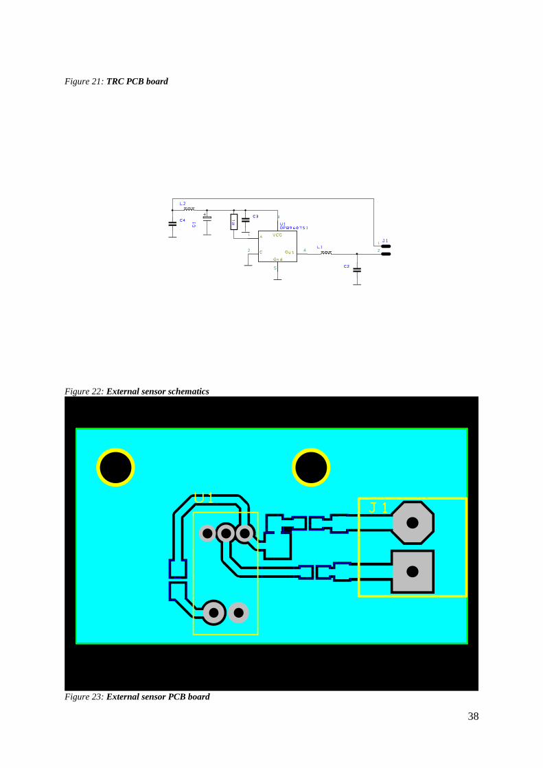
Figure 21: TRC PCB board
Figure 22: External sensor schematics
Figure 23: External sensor PCB board

39
Appendix B URC diagram and PCB boards design
Figure 24: Main URC schematics
Figure 25: Main URC PCB board

40
Figure 26: LCD schematics
Figure 27: LCD PCB board mounting pannel

41
Figure 28: LCD PCB board
Appendix C URC prototype photos
Figure 29: URC prototype starting screen

42
Figure 30: URC prototype azimuth and elevation screen
Figure 31: URC prototype wiring

43
Figure 32: URC prototype back panel
Appendix D BOM
NAME BOM QTTY
2 way Pin Header DSC 1
3 way Pin Header DSC 1
4 way Pin Header DSC 1
5 way Pin Header DSC 1
6 WP USER 2
8 PIN USER 1
10 WP USER 1
12 WP USER 1

44
FUSE T2a/250v 2
Voltage Regulator DSC 1
2 WP_Screw 2
6 PIN_SCREW 2
5 PIN 2
ADM3202
1
C0603 Capacitor 100nF 13
C0805 Capacitor 1uF 44
C1206 Capacitor 1uF 2
C7343 Capacitor 10uF 2
CRYSTALSMD 8MHz CrystalsVarious standard crystals 1
FB0603 15
FM24V10 SM 1
LMC6482A 2
LT1129-3.3 USER 1
NFM21_0805 Capacitor 47nF 1
VISHAY SEMICONDUCTOR TSOP4840 IR RECEIVER, 40KHZ 1
R0603 Resistor 3.3
28
RV_5mm 20k RV_5mm USER 6
STM32F405VGT6 IC MCU, 32BIT, 1MB FLASH, 100LQFP
QFP50P1600X1600X160-100N
1
VNQ810-E 2
Zener 6
MIDAS MCCOG22005A6W-BNMLWI LCD, COG 20X2, I2C BSTN WHITE
ON BLUE
1
VNH5019A-E 2
Figure 33: Bill of material

45
Appendix E Motor driver board sample code
/*
* motors.c
*
* Created on: 15.05.2016
* Author: Miroslav Rolko
*/
#include "motors.h"
#include "encoders.h"
#include "timers.h"
volatile uint8_t motor_state_az;
volatile uint8_t motor_state_el;
volatile uint8_t motor_pwr_state_az;
volatile uint8_t motor_pwr_state_el;
volatile uint16_t motor_voltage;
motor_map_t motor_ctrl_map[]= // Set number of output pins in array
.port=GPIOB, .pin=GPIO_Pin_1, //Settings azimuth
.port=GPIOA, .pin=GPIO_Pin_6,
.port=GPIOB, .pin=GPIO_Pin_0,
.port=GPIOA, .pin=GPIO_Pin_7,
.port=GPIOE, .pin=GPIO_Pin_9, //PWM pin
.port=GPIOE, .pin=GPIO_Pin_14, //Settings elevation
.port=GPIOE, .pin=GPIO_Pin_10,
.port=GPIOE, .pin=GPIO_Pin_13,
.port=GPIOE, .pin=GPIO_Pin_12,
.port=GPIOE, .pin=GPIO_Pin_11 //PWM pin
;
led_map_t led_map[]=
.port=GPIOD, .pin=GPIO_Pin_8,
.port=GPIOD, .pin=GPIO_Pin_9,
.port=GPIOD, .pin=GPIO_Pin_10,
.port=GPIOD, .pin=GPIO_Pin_11,
.port=GPIOD, .pin=GPIO_Pin_15, //LEDS ###
;
void motor_init(void)
GPIO_InitTypeDef GPIO_InitStructure; //Motor initializing
uint8_t i;
GPIO_InitStructure.GPIO_Mode=GPIO_Mode_OUT;
GPIO_InitStructure.GPIO_PuPd = GPIO_PuPd_NOPULL;
GPIO_InitStructure.GPIO_OType=GPIO_OType_PP;
GPIO_InitStructure.GPIO_Speed = GPIO_Speed_50MHz;
for( i=0; i<11; i++) //Add number of output pins in array
GPIO_InitStructure.GPIO_Pin = motor_ctrl_map[i].pin;
GPIO_Init( motor_ctrl_map[i].port, &GPIO_InitStructure);
for( i=0; i<11; i++) //Reset bits for motor outputs

46
GPIO_ResetBits( motor_ctrl_map[i].port, motor_ctrl_map[i].pin );
for( i=0; i<5; i++) //Reset bits for LED outputs
GPIO_InitStructure.GPIO_Pin = led_map[i].pin;
GPIO_Init( led_map[i].port, &GPIO_InitStructure);
for( i=0; i<5; i++)
GPIO_ResetBits( led_map[i].port, led_map[i].pin );
motor_state_az = MOTOR_OFF;
motor_state_el = MOTOR_OFF;
motor_pwr_state_az = 0;
motor_pwr_state_el = 0;
void motor_ctrl(uint8_t az_el, uint8_t state)
if( az_el == MOTOR_AZ)
if(!motor_pwr_state_az) motor_pwr_ctrl( MOTOR_AZ, ON );
if( state == MOTOR_CW )
GPIO_SetBits(motor_ctrl_map[MOTOR_CTRL_AZ_PWM].port,
motor_ctrl_map[MOTOR_CTRL_AZ_PWM].pin); //PWM ON
GPIO_SetBits(motor_ctrl_map[MOTOR_CTRL_AZ_IN_A].port,
motor_ctrl_map[MOTOR_CTRL_AZ_IN_A].pin); //1 //1
GPIO_ResetBits(motor_ctrl_map[MOTOR_CTRL_AZ_IN_B].port,
motor_ctrl_map[MOTOR_CTRL_AZ_IN_B].pin); //0
GPIO_SetBits(motor_ctrl_map[MOTOR_CTRL_AZ_EN_A_DIAG_A].port,
motor_ctrl_map[MOTOR_CTRL_AZ_EN_A_DIAG_A].pin); //1
GPIO_SetBits(motor_ctrl_map[MOTOR_CTRL_AZ_EN_B_DIAG_B].port,
motor_ctrl_map[MOTOR_CTRL_AZ_EN_B_DIAG_B].pin); //1 ###
led_ctrl(LED_CW, ON);
Delay(2000);
led_ctrl(LED_CW, OFF);
else if( state == MOTOR_CCW )
//GPIO_SetBits(motor_ctrl_map[MOTOR_CTRL_AZ_PWM].port,
motor_ctrl_map[MOTOR_CTRL_AZ_PWM].pin); //PWM ON
GPIO_ResetBits(motor_ctrl_map[MOTOR_CTRL_AZ_IN_A].port,
motor_ctrl_map[MOTOR_CTRL_AZ_IN_A].pin); //0
GPIO_SetBits(motor_ctrl_map[MOTOR_CTRL_AZ_IN_B].port,
motor_ctrl_map[MOTOR_CTRL_AZ_IN_B].pin); //1
GPIO_SetBits(motor_ctrl_map[MOTOR_CTRL_AZ_EN_A_DIAG_A].port,
motor_ctrl_map[MOTOR_CTRL_AZ_EN_A_DIAG_A].pin); //1
GPIO_SetBits(motor_ctrl_map[MOTOR_CTRL_AZ_EN_B_DIAG_B].port,
motor_ctrl_map[MOTOR_CTRL_AZ_EN_B_DIAG_B].pin); //1 ###
led_ctrl(LED_CCW, ON);
Delay(2000);
led_ctrl(LED_CCW, OFF);
motor_state_az = state;

47
else if( az_el == MOTOR_EL)
if(!motor_pwr_state_el) motor_pwr_ctrl( MOTOR_EL, ON );
if( state == MOTOR_UP )
GPIO_SetBits(motor_ctrl_map[MOTOR_CTRL_AZ_PWM].port,
motor_ctrl_map[MOTOR_CTRL_AZ_PWM].pin); //PWM ON
GPIO_SetBits(motor_ctrl_map[MOTOR_CTRL_EL_IN_A].port,
motor_ctrl_map[MOTOR_CTRL_EL_IN_A].pin); //1
GPIO_ResetBits(motor_ctrl_map[MOTOR_CTRL_EL_IN_B].port,
motor_ctrl_map[MOTOR_CTRL_EL_IN_B].pin); //0
GPIO_SetBits(motor_ctrl_map[MOTOR_CTRL_EL_EN_A_DIAG_A].port,
motor_ctrl_map[MOTOR_CTRL_EL_EN_A_DIAG_A].pin); //1
GPIO_SetBits(motor_ctrl_map[MOTOR_CTRL_EL_EN_B_DIAG_B].port,
motor_ctrl_map[MOTOR_CTRL_EL_EN_B_DIAG_B].pin); //1 ###
else if( state == MOTOR_DN )
// GPIO_SetBits(motor_ctrl_map[MOTOR_CTRL_AZ_PWM].port,
motor_ctrl_map[MOTOR_CTRL_AZ_PWM].pin); //PWM ON
GPIO_ResetBits(motor_ctrl_map[MOTOR_CTRL_EL_IN_A].port,
motor_ctrl_map[MOTOR_CTRL_EL_IN_A].pin); //0
GPIO_SetBits(motor_ctrl_map[MOTOR_CTRL_EL_IN_B].port,
motor_ctrl_map[MOTOR_CTRL_EL_IN_B].pin); //1
GPIO_SetBits(motor_ctrl_map[MOTOR_CTRL_EL_EN_A_DIAG_A].port,
motor_ctrl_map[MOTOR_CTRL_EL_EN_A_DIAG_A].pin); //1
GPIO_SetBits(motor_ctrl_map[MOTOR_CTRL_EL_EN_B_DIAG_B].port,
motor_ctrl_map[MOTOR_CTRL_EL_EN_B_DIAG_B].pin); //1 ###
else
motor_state_el = state;
int8_t motor_get_state( uint8_t az_el) //state of the motor
if( az_el == MOTOR_AZ)
return motor_state_az;
else if( az_el == MOTOR_EL)
return motor_state_el;
else return -1;
void led_ctrl(uint8_t led, bool_t state) //set state of the LEDS

48
if( state ) GPIO_SetBits(led_map[led].port, led_map[led].pin);
else GPIO_ResetBits( led_map[led].port, led_map[led].pin );
void motor_pwr_ctrl( uint8_t az_el, bool_t state ) //power of the LEDS
if(az_el == MOTOR_AZ)
if( state )
GPIO_SetBits(led_map[LED_PW].port, led_map[LED_PW].pin);
motor_pwr_state_az = ON;
else
GPIO_ResetBits(led_map[LED_PW].port, led_map[LED_PW].pin);
motor_pwr_state_az = OFF;
else
if( state )
GPIO_SetBits(led_map[LED_PW].port, led_map[LED_PW].pin);
motor_pwr_state_el = ON;
else
GPIO_ResetBits(motor_ctrl_map[LED_PW].port, motor_ctrl_map[LED_PW].pin);
motor_pwr_state_el = OFF;
bool_t motor_get_pwr_state( uint8_t az_el ) //power of the motor
if(az_el == MOTOR_AZ)
return motor_pwr_state_az;
else
return motor_pwr_state_el;
Figure 34: Sample of code for rotating motor in azimuth and elevation
Authorization

49
Non-exclusive license to reproduce thesis and make thesis public
I, Miroslav Rolko ,
herewith grant the University of Tartu a free permit (non-exclusive license) to:
1.1. reproduce, for the purpose of preservation and making available to the public, including
for addition to the DSpace digital archives until expiry of the term of validity of the copyright,
and
1.2. make available to the public via the web environment of the University of Tartu,
including via the DSpace digital archives until expiry of the term of validity of the copyright,
Universal antenna rotator controller for satellite ground stations,
supervised by Viljo Allik and Indrek Sünter,
2. I am aware of the fact that the author retains these rights.
3. I certify that granting the non-exclusive license does not infringe the intellectual property
rights or rights arising from the Personal Data Protection Act.
Tartu, 23.05.2016