Embed Size (px)
Citation preview

UNIVERSITY OF NORTHERN COLORADO June 2015 FACILITY STANDARDS
16-1
DIVISION 16 - ELECTRICAL GENERAL PROVISIONS
Facility Services will provide information regarding preferred locations for tie-ins to existing utilities.
Utility outages will generally need to be scheduled outside of normal working hours and will often include weekends and holidays. Specifications will need to include this requirement at no additional cost to the owner.
Utilize 277/480 VAC for all lighting systems and equipment loads where feasible.
Provide training for all systems
Provide minimum of three copies of O&M Manuals covering:
Alphabetical listing of all system components with Name, address & phone number of company responsible for first year service and source of replacement parts
Operating Instructions normal starting, operating & shut-down emergency procedures summer & winter special procedures (if any) day & night special procedures (if any)
Maintenance Instructions lubricating instructions cleaning, replacement or adjustment schedule
Manufacturers data for each piece of equipment Installation instructions drawings and specifications parts list, including recommended spares complete wiring diagrams
marked prints showing all concealed parts and variations from the original system design
test and inspection certifications

UNIVERSITY OF NORTHERN COLORADO June 2015 FACILITY STANDARDS
16-2
DESIGN DATA
Electrical designer shall provide a report indicating the complete load data for each project. Data to include total connected load, connected lighting load, connected mechanical load and other connected loads.
Designer will also submit calculations of available fault current at all points within the electrical distribution system. Interrupt or withstand ratings that exceed the values determined in these calculations will be required for all electrical equipment specified in the design.
ELECTRICAL IDENTIFICATION
Buried raceways shall be installed with suitable marker tape approximately 1' above the raceway.
Paint covers of all boxes for fire alarm systems red.
Provide arc flash labeling on all equipment, panel boards, switchgear, etc.
Label all box covers with permanent marker indicating the circuits contained.
Provide circuit and panel identification on the inside face of all switch and receptacle covers. Label with permanent marker.
Use wire markers to ID circuits in junction boxes
Label panel boards with engraved plastic nameplates indicating Panel designation, voltage, loads served. Nameplate to be mechanically fastened.
Provide typed panel schedule in each panel and switchboard. Panel schedules shall provide specific information for each circuit indicating rooms or equipment served.
Switches, starters and similar equipment shall be labeled with load served and source of power. Use engraved plastic nameplates.
SPARE FUSES
Provide a minimum of three spare fuses of each size and type used.

UNIVERSITY OF NORTHERN COLORADO June 2015 FACILITY STANDARDS
16-3
Provide a suitable spare fuse cabinet, mounted securely in a location designated by the owner.
Specifically include fuses for high voltage equipment and transformers. HIGH VOLTAGE EQUIPMENT
For most buildings high voltage power will be connected to University owned distribution systems and will be routed via new concrete encased duct banks.
The University primary system voltage is 12,470 VAC. Delta Primary, Wye secondary.
Transformers for high voltage systems shall be exterior pad mounted equipment. Locate as directed by the owner. Transformers shall be non-PCB liquid cooled. Transformer size to be determined by the Engineer and reviewed by Facilities Management.
All transformers to include internal switching capability with an “OFF” position to isolate the secondary.
High Voltage sectionalizing switch gear for west campus shall be pad mounted S&C Vista switches. High voltage switches for the Central Campus are incorporated into the transformers.
High voltage cable shall be installed in a concrete encased underground duct bank. Conduit may be PVC type 1 or equivalent. All elbows shall be PVC coated galvanized rigid steel.
High voltage cable shall be manufactured by Okanite. Okoguard – Okoseal Type MV-105
Provide fault indicators for all high voltage cable runs. FCI load tracker by Power Delivery Products Inc.
Load break elbow terminations shall be Elastimold #166LR and 655LR submersible, or approved equivalent
Splices and lug type terminations shall be Elastimold or Ray-chem. RACEWAYS / BOXES

UNIVERSITY OF NORTHERN COLORADO June 2015 FACILITY STANDARDS
16-4
Conduit
Use EMT, Rigid and PVC in areas as required by code. Flexible conduit and MC cable shall be limited to light fixture whips, and final connections to equipment.
All conduit of any type must contain a ground wire.
All panels shall have a minimum of 4 empty 1" conduits stubbed out to an accessible location for future use.
Provide minimum ¾” trade size conduit for all branch circuit homerun conduits to allow for potential future expansion. Verify with Owner for each facility.
Raceways shall be supported from structure. Raceways shall not be supported by suspended ceiling system members or support wires.
Fittings for EMT shall be steel compression gland or steel set screw type only.
Provide conduits with pull wires for telecommunications use. Provide blank cover plates for all unused conduits.
Conduits to be installed in floor slabs shall be approved by structural engineer. No conduit larger than ¾” trade size shall be installed in any floor slab.
All elbows for PVC conduits shall be plastic coated rigid steel.
Provide empty conduits with pull wires in all classrooms for projection equipment and control, instructors stations, TV and video equipment, ceiling mounted projectors, etc.
Surface raceway shall be metal. Do not specify plastic products.
Provide a minimum of 3 – 4”, schedule 40 PVC conduits between the building and the nearest utility tunnel for telephone, data, TV, etc. Confirm size, quantity and location with Facilities Management.
Provide warning tape buried above all exterior underground conduits and ductbanks.
UNIVERSITY OF NORTHERN COLORADO June 2015 FACILITY STANDARDS
16-5
Boxes
Sectionalized type boxes are not permitted
Boxes for outlets, switches etc. shall be 4" x 4" minimum with appropriate mud ring.
Coordinate access doors as required to provide access to boxes in hard ceilings and similar inaccessible areas. Type of access door shall be coordinated with the Architect.
Do not allow back to back boxes. WIRE AND CABLE
All conductors shall be copper. Use of aluminum conductors is not permitted. All conductors that attach to devices shall be solid conductors.
Wire and cable shall generally be type THHN, THWN or THW
Do not specify non-metallic cable (type NM oro NM-C), Metal clad cable (type AC or MC)
In no case shall conductor smaller than # 12 AWG be used for lighting or receptacle branch circuits. For branch circuits whose length from panel to the furthest outlet exceeds 100 feet for 120V circuits use # 10 AWG or larger.
Wire or cable for specialized installations shall be as recommended by the Project Engineer
Specify a grounding conductor in all branch circuit raceways.
All circuits to have separate neutral. Do not use handle ties.
Color coding shall be as follows: VOLTAGE A PHASE B PHASE C PHASE NEUTRAL GND 120/208V Black Red Blue White Green 277/480V Brown Orange Yellow Gray Green

UNIVERSITY OF NORTHERN COLORADO June 2015 FACILITY STANDARDS
16-6
Switch legs shall be separate colors from those identified above. WIRE JOINTS AND CONNECTIONS
Joints in wires
# 8 and smaller - twist wires and secure with twist-on, expandable spring type solderless connectors with insulated shell
# 6 and larger - use solderless compression type lugs and connectors, insulated with half lapped layers of vinyl plastic electrical tape
WIRING DEVICES
All wiring devices shall be specification grade, suitable for high abuse locations, grounding type with separate grounding screw.
Do not specify “Decora” style devices.
All devices shall be designed for mechanical screw connection. Push in connections are not permitted.
Lighting switches in mechanical rooms and similar locations shall be a lighted when off handle type switch.
Devices shall be connected to a circuit with a pigtail from a splice. Do not wire the circuit directly through the device.
Face plates for classrooms, offices labs and similar spaces shall be 302 stainless steel. Face plates for residential applications should generally be nylon. Where two or more devices are shown in one location, mount under a common plate.
Switches - quiet operating, toggle operator, self grounding metal strap. Rated 20A at 120-277V.
Duplex convenience receptacles shall be 3 pole, 2 parallel blades and 1 grounding blade. Rated 20A at 125V AC.
Devices to be ivory or white in color unless approved by owner. Special purpose outlets shall be color coded:
Isolated ground – Orange
Emergency – Red.

UNIVERSITY OF NORTHERN COLORADO June 2015 FACILITY STANDARDS
16-7
Provide a welding outlet in each mechanical room located as directed by Facilities Management. NEMA 10-30R, 30 A, 125 / 250V
MOTORS
Specify a motor control center whenever possible.
Motors to be high quality, long life, general purpose, continuous duty, design “B” except “C” where required for high starting torque. Premium Efficiency (91% – 94%)
Phase protection shall be supplied on all 3 Phase motor loads.
Motors 3/4 HP and larger to be 3 phase, ½ HP and smaller to be capacitor start single phase except 1/16 HP and smaller may be split phase type. All motors rated greater than 1000 watts shall have a power factor not less than 85% under rated load conditions. Service factor for three phase motors 1.15, single phase motors 1.35. Three phase motors shall have under voltage, phase failure and phase reversal protection on all legs.
Bearings to be L-50, 200,000 hour rated. Re-greasable except where motor is in-accessible for regular maintenance.
Provide “quiet” rating on motors. 80 DB or less at full speed and power.
Motors to have an expected useful of life 17 years.
Specify Invertor rated for use with Variable Frequency Drives.
Motors to be manufactured by Baldor, Century, US, Reliance, Westinghous.
Provide magnetic starters for motors 1/2 HP and larger and for smaller motors where interlock or automatic operation is required.
PANELBOARDS / SWITCHBOARDS
Panels to be three phase unless otherwise approved by Facilities Management.
Lighting and receptacle branch circuits shall be minimum 20 ampere.

UNIVERSITY OF NORTHERN COLORADO June 2015 FACILITY STANDARDS
16-8
Provide a minimum of 4 spare conduits out of each panel, routed to an accessible location.
A/E to provide panel schedules on the contract drawings. Drawings and schedules shall be consistent with room numbering as provided by Facilities Management.
All panels to have bolt-in breakers and hinged covers.
All panels to be lockable, and keyed alike for each particular project.
New panels shall be designed with a minimum of 30% spare capacity.
Panel designation shall be by type (lighting, power, emergency), floor and panel (A, B, etc.) ie: L2A, P3B, E1A
Panels to be manufactured by Square D, Cutler Hammer, Siemans. Panel Location
Panels shall be located on the same floor as the load served.
Panels are not to be located in custodial or other storage type spaces. Do not locate panels in laboratories, classrooms or behind doors. Locate in dedicated rooms wherever possible.
Switching of lighting with circuit breakers will only be acceptable when specifically approved by Facilities Management. Use contactors or low voltage switching systems. If switching at panels is approved, a separate panel shall be provided for circuits which are to be controlled. No circuits other than lighting will originate from this panel.
Main switchroom
Main switchboard rooms shall not contain other systems or equipment not related to the electrical distribution system
Specify filtered, thermostatically controlled ventilation for all main switchboard rooms.
Provide battery powered of emergency lighting in all main switchboard rooms.
METERING

UNIVERSITY OF NORTHERN COLORADO June 2015 FACILITY STANDARDS
16-9
All new buildings shall be individually metered with a microprocessor based metering package with digital readout. Meter to be Square D Power Logic Series 2000 or equivalent. Provide the following display functions:
AC amperes for each phase
AC voltage - phase to phase, phase to neutral
Watts
Power factor
Frequency
Watt demand
Watt Hours
Provide factory meter start up during commissioning. LIGHTING Interior lighting
All light fixtures shall be located so that they are easily accessible for re-lamping and maintenance activities. For example, do not locate ceiling fixtures over stairs or open light wells.
All lighting design shall be based on the latest edition of IES Lighting Handbook
Preferred lighting for classrooms, corridors and common areas is 2’ X 4’ or 2’ X 2’ direct / indirect type fixture. Consider special needs such as lighting on chalk / marker boards in classrooms. Specialty lighting for classrooms and other spaces shall be reviewed with the Owner.
All office or classroom lighting where three or four lamp fluorescent lighting fixtures are used shall be controlled by separately switched ballast’s to provide two level lighting capability.
Linerar fluorescent lamps shall be T6 or T8, color rendering index as approved by Facilities Management.
Incandescent lamps shall be extended service type, inside frosted rated at 130Volts. Avoid the use of incandescent lighting.
Utilize LED type lamps where possible in lieu of incandescent.

UNIVERSITY OF NORTHERN COLORADO June 2015 FACILITY STANDARDS
16-10
Fluorescent light fixtures shall use electronic ballasts. as manufactured by Motorolla, triad Ultrad or Advance VII. Total harmonic distortion shall be less than 10% with third harmonic distortion less than 8%. Crest factor less than 1.5 . Power factor .98 or higher and ballast efficiency 90% or higher. UL listed class P, sound rating better than A. Electromagnetic interference less than 54 db from 450 KHz to 30 MHz. Provide 3 year manufacturers warranty.
Limit the use of two stage ballasts.
Use of dimming fluorescent lighting must be approved by Facilities Management.
Consider the use of highly polished reflectors, occupancy sensors (Watt Stopper, Hubble, Leviton) and other energy savings devices and equipment. Ceiling mounted motion detectors shall also be wired to a wall switch.
Require independent support for all fixtures. Do not rely on ceiling tiles for support.
Specify wire guards on fixtures in mechanical spaces and other locations as appropriate.
Exit lighting shall be LED type as manufactured by Lithonia, Prescolite
Emergency lighting units and battery pack units shall be by Lithonia, Exide or as approved by Facilities Management. Consider use of emergency generators for new facilities rather than battery packs if the load and budget permits.
Do not specify standard light fixtures with emergency batteries. Exterior lighting
The outdoor pole light to be specified for use in campus parking lots is as follows: One or two head Metal Halide luminaires, on square straight steel poles (25 ft). Luminaire manufactured by Gardco. EH-19-1-3-250MH-277-SC-GTS-25-11-7-DI-SC-UNC Norton Blue. Equivalent by Kim Lighting.(Designer to confirm voltage, lamp size etc.) LED options should be evaluated.
Design for 2.5 to 3 foot candles minimum in parking lots with a uniformity ratio of 4 to1.

UNIVERSITY OF NORTHERN COLORADO June 2015 FACILITY STANDARDS
16-11
Lighting for walkways on West campus shall be as follows: Lumec 70MH-DMS50-SG3-277-CNI-IA-FB-SC-SM6-14-SC-UNC Norton Blue. (12 ft poles may be appropriate for some locations.) Equivalent by Architectural Area Lighting.
The decorative exterior pole lights in use for walkways on central campus are as follows: pole mounted luminaries with cast iron base, acorn globe with solid lid, 15 ft. cast iron pole, powder coat finish and stainless steel tamper resistant hardware. Antique street lamps Inc. by Lithonia Lighting. Product number: Holophane NY15/17-CIS/CM Pole, L_ _ _/5RSL9P_CM-S150/277 Luminaire. 1- 150W HPS lamp. Also consider 40 watt induction and LED options.
Design walkway lighting for 1.5 to 2 fc.
Custom Color poles and luminaries are required. Powder coat color RAL 5003 Sapphire blue.
Outdoor pole bases shall be 6” above finish grade in landscaped areas and 2’ above grade where vehicular contact is possible. Coordinate concrete base detail and decorative collar with Facilities Management.
Pole bases shall have one additional conduit stub out for future
Outdoor lighting is to be controlled by the building automation system where possible. Coordinate with the mechanical controls specifications.
Do not specify Bollard Lighting Systems
Provide a luminaire schedule on the drawings listing the following information:
luminaire identification
description
manufacturer and catalog number
voltage
lamps (number and type)
mounting with required recess depth
mounting height
two alternate manufacturers
watts per fixture
Submit catalog information for owners review during design for all proposed light fixtures

UNIVERSITY OF NORTHERN COLORADO June 2015 FACILITY STANDARDS
16-12
SECTION 16721 FIRE DETECTION AND ALARM PART 1.0 - GENERAL
1.1. DESCRIPTION:
A. This section of the specification includes the furnishing, installation, and
connection and certification of a microprocessor controlled, analog addressable,
intelligent fire alarm equipment required to form a complete coordinated system
ready for operation. It shall include, but not be limited to, alarm initiating devices,
alarm notification appliances, control panels, auxiliary control devices,
annunciators, power supplies, and wiring as shown on the drawings and specified
herein.
B. The fire alarm system shall comply with requirements of NFPA Standard
72 for Protected Premises Signaling Systems except as modified and
supplemented by this specification. The system shall be electrically supervised
and monitor the integrity of all conductors.
C. The system shall be an active/interrogative type system where each
addressable device is repetitively scanned, causing a signal to be transmitted to the
main fire alarm control panel (FACP) indicating that the device and its associated
circuit wiring is functional. Loss of this signal at the main FACP shall result in a
trouble indication as specified hereinafter for the particular input.
D. The fire alarm system shall be manufactured by an ISO 9001 certified
company and meet the requirements of BS EN9001: ANSI/ASQC Q9001-1994.
E. The system and its components shall be Underwriters Laboratories, Inc.
listed under the appropriate UL testing standard as listed herein for fire alarm
applications and the installation shall be in compliance with the UL listing.
1.2. SCOPE:
A. A new intelligent reporting, microprocessor controlled fire detection
system shall be installed in accordance with the specifications and drawings.
B. The system shall be designed such that each signaling line circuit (SLC) is
limited to only 80% of its total capacity at initial installation.

UNIVERSITY OF NORTHERN COLORADO June 2015 FACILITY STANDARDS
16-13
C. Basic Performance:
1. Alarm, trouble and supervisory signals from all intelligent reporting
devices shall be encoded on NFPA Style 4 (Class B) Signaling Line
Circuits (SLC).
2. Initiation Device Circuits (IDC) shall be wired Class B (NFPA Style Z)
as part of an addressable device connected by the SLC Circuit.
3. Notification Appliance Circuits (NAC) shall be wired Class B (NFPA
Style Y) as part of an addressable device connected by the SLC Circuit.
4. On Style 4 (Class B) configurations a single ground fault or open
circuit on the system Signaling Line Circuit (SLC) shall not cause system
malfunction, loss of operating power or the ability to report an alarm.
5. Alarm signals arriving at the FACP shall not be lost following a
primary power failure (or outage) until the alarm signal is processed and
recorded.
D. BASIC SYSTEM FUNCTIONAL OPERATION
When a fire alarm condition is detected and reported by one of the system
initiating devices, the following functions shall immediately occur:
1. The system alarm LED on the system display shall flash.
2. A local piezo electric signal in the control panel shall sound.
3. A backlit LCD display shall indicate all information associated with the
fire alarm condition, including the type of alarm point and its location
within the protected premises.
4. History storage equipment shall log the information associated with
each new fire alarm control panel condition, along with time and date of
occurrence.
5. All system output programs assigned via control-by-event interlock
programming to be activated by the particular point in alarm shall be
executed, and the associated system outputs (notification appliances and/or
relays) shall be activated.
1.3. SUBMITTALS

UNIVERSITY OF NORTHERN COLORADO June 2015 FACILITY STANDARDS
16-14
A. General:
1. Submission of submittals for review and comment. In addition to
distribution requirements for Submittals specified in Division 1 Section
“Submittals”, make an identical submission to UNC facilities for review
and comment. After incorporating any Engineer/UNC Facilities
comments submit to Union Colony Fire/Rescue Authority (AHJ). Include
copies of annotated Contract Drawings as needed to depict component
locations to facilitate review. Resubmit if required to make clarifications
or revisions to obtain approval. Fire alarm shop drawings shall be sealed
and signed by a professional engineer (P.E.) licensed in Colorado, who
shall certify that the fire alarm installation meets requirements of the local
codes and applicable sections of NFPA. Additionally, a NICET level 3 or
4 Technician shall stamp fire alarm shop drawings. On receipt of
comments from authorities having jurisdiction, submit them to the Project
Architect/Engineer for review. Include all AHJ comments with the
submittal.
2. All references to manufacturer's model numbers and other pertinent
information herein is intended to establish minimum standards of
performance, function and quality. Equivalent compatible UL-listed
equipment from other manufacturers may be substituted for the specified
equipment as long as the minimum standards are met.
3. For equipment other than that specified, the contractor shall supply
proof that such substitute equipment equals or exceeds the features,
functions, performance, and quality of the specified equipment.
B. Shop Drawings:
1. Sufficient information, clearly presented, shall be included to determine
compliance with drawings and specifications.
2. Include manufacturer's name(s), model numbers, ratings, power
requirements, equipment layout, device arrangement, complete wiring
point-to-point diagrams, and conduit layouts.
3. Show annunciator layout, configurations, and terminations.
4. Battery back-up calculations will be submitted for approval.
C. Manuals:

UNIVERSITY OF NORTHERN COLORADO June 2015 FACILITY STANDARDS
16-15
1. Submit simultaneously with the shop drawings, complete operating and
maintenance manuals listing the manufacturer's name(s), including
technical data sheets.
2. Wiring diagrams shall indicate internal wiring for each device and the
interconnections between the items of equipment.
3. Provide a clear and concise description of operation that gives, in
detail, the information required to properly operate the equipment and
system.
D. Software Modifications
1. Provide the services of a factory trained and authorized technician to
perform all system software modifications, upgrades or changes.
Response time of the technician to the site shall not exceed 2 hours.
2. Provide all hardware, software, programming tools, source codes and
documentation necessary to modify the fire alarm system on site.
Modification includes addition and deletion of devices, circuits, zones and
changes to system operation and custom label changes for devices or
zones. The system structure and software shall place no limit on the type
or extent of software modifications on-site.
E. Certifications:
1. Together with the shop drawing submittal, submit a certification from
the major equipment manufacturer indicating that the proposed supervisor
of the installation and the proposed performer of contract maintenance is
an authorized representative of the major equipment manufacturer. Include
names and addresses in the certification.
2. Certificate of Completion: Comply with NFPA 72.
1.4. GUARANTY:
A. All work performed and all material and equipment furnished under this
contract shall be free from defects and shall remain so for a period of at
least one (1) year from the date of acceptance. The full cost of
maintenance, labor and materials required to correct any defect during this
one year period shall be included in the submittal bid.
B. Provide the Owner with a three year guaranteed price list of parts used on
the project for replacement.

UNIVERSITY OF NORTHERN COLORADO June 2015 FACILITY STANDARDS
16-16
1.5. APPLICABLE STANDARDS AND SPECIFICATIONS:
The specifications and standards listed below form a part of this specification. The
system shall fully comply with the latest issue of these standards, if applicable.
A. National Fire Protection Association (NFPA) - USA:
No. 12 CO2 Extinguishing Systems (low and high)
No. 12B Halon 1211 Extinguishing Systems
No. 13 Sprinkler Systems
No. 13A Halon 1301 Extinguishing Systems
No. 15 Water Spray Systems
No. 16 Foam/Water Deluge and Spray Systems
No. 17 Dry Chemical Extinguishing Systems
No. 17A Wet Chemical Extinguishing Systems
Clean Agent Extinguishing Systems
No. 72 National Fire Alarm Code
No. 101 Life Safety Code
B. Underwriters Laboratories Inc. (UL) - USA:
No. 268 Smoke Detectors for Fire Protective Signaling Systems
No. 864 Control Units for Fire Protective Signaling Systems
No. 268A Smoke Detectors for Duct Applications
No. 521 Heat Detectors for Fire Protective Signaling Systems
No. 464 Audible Signaling Appliances
No. 38 Manually Actuated Signaling Boxes
No. 346 Water flow Indicators for Fire Protective Signaling
Systems
No. 1076 Control Units for Burglar Alarm Proprietary Protective
Signaling Systems
No. 1971 Visual Notification Appliances
UUKL
C. Local and State Building Codes.
D. All requirements of the Authority Having Jurisdiction (AHJ).
1.6. APPROVALS:
A. The system shall have proper listing and/or approval from the following
nationally recognized agencies:

UNIVERSITY OF NORTHERN COLORADO June 2015 FACILITY STANDARDS
16-17
UL Underwriters Laboratories Inc
ULC Underwriters Laboratories Canada
FM Factory Mutual
MEA Material Equipment Acceptance (NYC)
CSFM California State Fire Marshal
B. The fire alarm control panel shall meet UL Standard 864 (Control Units)
and UL Standard 1076 (Proprietary Burglar Alarm Systems).
C. The system shall be listed by the national agencies as suitable for
extinguishing release applications. The system shall support release of
high and low pressure CO2.
D. Modular Labeling: The fire alarm control panel shall meet the modular
listing requirements of Underwriters Laboratories Inc. To facilitate system
changes and expansions, and to ensure that all subassemblies have the
proper listing, each subassembly of the FACP shall carry the appropriate
UL modular label. This includes all printed circuit board assemblies,
power supplies, and enclosure parts.
1.7 QUALITY ASSURANCE
A. Installer Qualifications: An experienced installer with a minimum of 5
years fire alarm installation experience and NICET Level 2 Technician or
greater supervising the installation. The installing technician shall provide
written proof of NICET level 2 certification to UNC.
B. Authorized distributor: The manufacturer’s authorized distributor shall
confirm that they have an established agency which stocks a full
complement of parts and offers service during normal working hours on
all equipment to be furnished and that the agency will supply parts and
service without delay and at a reasonable cost. Maximum response time
for service calls is two hours or less.
C. The work described in this specification consists of all labor, materials,
equipment, and services necessary and required to complete and test the

UNIVERSITY OF NORTHERN COLORADO June 2015 FACILITY STANDARDS
16-18
automatic fire detection and alarm system. Any material not specifically
mentioned in this specification or not shown on drawings, but required for
proper performance and operation as specified, shall be furnished and
installed and considered part of the system at no extra charge to the
Owner.
1.8 EXTRA MATERIALS
A. Furnish extra materials described below that match products installed for
all systems and that are packaged with protective covering for storage and
identified with labels describing contents.
1. Strobe Units, Horn units and horn/strobe combination units, speaker
and speaker/strobe combination units: Quantity equal to 5 percent of
amount installed, but not less than one unit of each type.
2. Smoke Detectors, Heat/Fire Detectors, and Flame Detectors: Quantity
equal to 5 percent of amount of each type installed, but not less than one
unit of each type.
3. Detector Bases: Quantity equal to 2 percent of amount of each type
installed, but not less than one unit of each type.
4. Manual pull stations, monitor modules and control modules: Quantity
equal to 5 percent of amount of each type installed, but not less than one unit of
each type.
5. Keys and Tools: One extra set for access to locked and tamper proof
components.
PART 2.0 - PRODUCTS
2.1 MANUFACTURERS
A. Subject to compliance with the specified requirements, provide products
by either Notifier or Honeywell. Dependingupon project size requirements,
provide either a Notifier NFS-2 -3030, NFS-2 640, NFS-2 320 system or a
Honeywell XLS140-2, XLS-200, XLS-1000 or XLS-3000 with system sensor
devices. These systems are to be networked into the campus Honeywell EBi
network in the case of a Honeywell system and the campus Notifier Onyxworks
network in the case of a Notifier system.

UNIVERSITY OF NORTHERN COLORADO June 2015 FACILITY STANDARDS
16-19
2.2. EQUIPMENT AND MATERIAL, GENERAL:
A. All equipment and components shall be new, and the manufacturer's
current model. The materials, appliances, equipment and devices shall be tested
and listed by a nationally recognized approvals agency for use as part of a
protected premises protective signaling (fire alarm) system. The authorized
representative of the manufacturer of the major equipment, such as control panels,
shall be responsible for the satisfactory installation of the complete system.
B. All equipment and components shall be installed in strict compliance with
manufacturers' recommendations. Consult the manufacturer's installation manuals
for all wiring diagrams, schematics, physical equipment sizes, etc., before
beginning system installation. Refer to the Riser/Connection diagram for all
specific system installation/termination/wiring data.
C. All equipment shall be attached to walls and ceiling/floor assemblies and
shall be held firmly in place (e.g., detectors shall not be supported solely by
suspended ceilings). Fasteners and supports shall be adequate to support the
required load.
2.3. CONDUIT AND WIRE:
A. Conduit:
1. Conduit shall be in accordance with The National Electrical Code
(NEC), local and state requirements.
2. Where possible, all wiring shall be installed in conduit or raceway.
Conduit fill shall not exceed 40 percent of interior cross sectional area
where three or more cables are contained within a single conduit.
3. Cable must be separated from any open conductors of Power, or Class
1 circuits, and shall not be placed in any conduit, junction box or raceway
containing these conductors, as per NEC Article 760-29.
4. Wiring for 24 volt control, alarm notification, emergency
communication and similar power-limited auxiliary functions shall not be
run in the same conduit as initiating and signaling line circuits. All circuits
shall be provided with transient suppression devices and the system shall
UNIVERSITY OF NORTHERN COLORADO June 2015 FACILITY STANDARDS
16-20
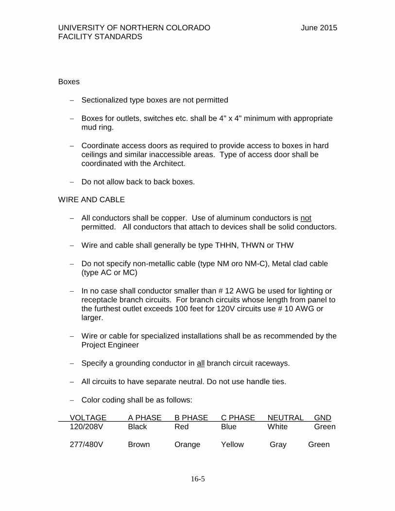
be designed to permit simultaneous operation of all circuits without
interference or loss of signals.
5. Conduit shall not enter the fire alarm control panel, or any other
remotely mounted control panel equipment or back boxes, except where
conduit entry is specified by the FACP manufacturer.
6. Conduit shall be 3/4 inch (19.1 mm) minimum.
B. Wire:
1. All fire alarm system wiring must be new.
2. Wiring shall be in accordance with local, state and national codes (e.g.,
NEC Article 760) and as recommended by the manufacturer of the fire
alarm system. Number and size of conductors shall be as recommended by
the fire alarm system manufacturer, but not less than 18 AWG (1.02 mm)
for initiating device circuits and signaling line circuits, and 14 AWG (1.63
mm) for notification appliance circuits.
3. All wire and cable shall be listed and/or approved by a recognized
testing agency for use with a protective signaling system.
4. Wire and cable not installed in conduit shall have a fire resistance
rating suitable for the installation as indicated in NFPA 70 (e.g., FPLR).
5. Wiring used for the multiplex communication circuit (SLC) shall be
twisted and unshielded and support a minimum wiring distance of 12,500
feet. The design of the system shall permit use of IDC and NAC wiring in
the same conduit with the SLC communication circuit.
6. All field wiring shall be electrically supervised for open circuit and
ground fault.
7. The Fire Alarm Control panel shall be capable of T-Tapping Class B
(NFPA Style 4) Signaling Line Circuits. Systems which do not allow, have
restrictions to, for example, the amount of T-Taps, length of T-Taps etc.,
are not acceptable.
8. Wiring connecting remote fire alarm panels shall be capable of
supporting voice signals.
C. Terminal Boxes, Junction Boxes and Cabinets:

UNIVERSITY OF NORTHERN COLORADO June 2015 FACILITY STANDARDS
16-21
All boxes and cabinets shall be UL listed for their use and purpose.
D. Initiating circuits shall be arranged to serve like categories (manual,
smoke, water flow). Mixed category circuitry shall not be permitted except on
signaling line circuits connected to intelligent reporting devices.
E. The fire alarm control panel shall be connected to a separate dedicated
branch circuit, maximum 20 amperes. This circuit shall be labeled at the main
power distribution panel as FIRE ALARM. Fire alarm control panel primary
power wiring shall be 12 AWG.
2.4. MAIN FIRE ALARM CONTROL PANEL OR NETWORK NODE:
A. The main FACP Central Console shall contain a microprocessor based
Central Processing Unit (CPU). The CPU shall communicate with and control the
following types of equipment used to make up the system: intelligent addressable
smoke and thermal (heat) detectors, addressable modules, panel modules
including initiating circuits, control circuits, and notification appliance circuits,
local and remote operator terminals, printers, annunciators, and other system
controlled devices.
1. In conjunction with intelligent Loop Control Modules and Loop
Expander Modules, the main FACP shall perform the following functions:
a. Supervise and monitor all intelligent addressable detectors and
monitor modules connected to the system for normal, trouble and
alarm conditions.
b. Supervise all initiating signaling and notification appliance
circuits throughout the facility by way of connection to monitor
and control modules.
c. Detect the activation of any initiating device and the location of
the alarm condition. Operate all notification appliances and
auxiliary devices as programmed. In the event of CPU failure, all
SLC loop modules shall fallback to degrade mode. Such degrade
mode shall treat the corresponding SLC loop control modules and
associated detection devices as conventional two-wire operation.
Any activation of a detector in this mode shall automatically
activate associated Notification Appliance Circuits.
d. Visually and audibly annunciate any trouble, supervisory,
security or alarm condition on operator's terminals, panel display,
and annunciators.

UNIVERSITY OF NORTHERN COLORADO June 2015 FACILITY STANDARDS
16-22
2. When a fire alarm condition is detected and reported by one of the
system initiating devices or appliances, the following functions shall
immediately occur:
a. The system alarm LED shall flash.
b. A local piezo-electric audible device in the control panel shall
sound a distinctive signal.
c. The 640-character backlit LCD display shall indicate all
information associated with the fire alarm condition, including the type
of alarm point and its location within the protected premises.
d. History storage equipment shall log the event information along
with a time and date stamp.
e. All system outputs assigned via pre-programmed equations for a
particular point in alarm shall be executed, and the associated
system outputs (alarm notification appliances and/or relays) shall
be activated.
3. When a trouble condition is detected and reported by one of the system
initiating devices or appliances, the following functions shall immediately
occur:
a. The system trouble LED shall flash.
b. A local piezo-electric audible device in the control panel shall
sound a distinctive signal.
c. The 640-character backlit LCD display shall indicate all
information associated with the trouble condition, including the
type of trouble point and its location within the protected premises.
d. History storage equipment shall log the event information along
with a time and date stamp.
4. When a supervisory condition is detected and reported by one of the
system initiating devices or appliances, the following functions shall
immediately occur:
a. The system supervisory LED shall flash.

UNIVERSITY OF NORTHERN COLORADO June 2015 FACILITY STANDARDS
16-23
b. A local piezo-electric audible device in the control panel shall
sound a distinctive signal.
c. The 640-character backlit LCD display shall indicate all
information associated with the supervisory condition, including
the type of trouble point and its location within the protected
premises.
d. History storage equipment shall log the event information along
with a time and date stamp.
e. All system outputs assigned via pre-programmed equations for a
particular point in supervisory alarm shall be executed, and the
associated system outputs shall be activated.
5. When a pre-alarm condition is detected and reported by one of the
system initiating devices or appliances, the following functions shall
immediately occur:
a. The system pre-alarm LED shall flash.
b. A local piezo-electric audible device in the control panel shall
sound a distinctive signal.
c. The 640-character backlit LCD display shall indicate all
information associated with the pre-alarm condition, including the
type of alarm point and its location within the protected premises.
d. History storage equipment shall log the event information along
with a time and date stamp.
e. All system outputs assigned via pre-programmed equations for a
particular point in pre-alarm shall be executed, and the associated
system outputs shall be activated.
B. Operator Control
1. Acknowledge Switch:
a. Activation of the control panel acknowledge switch in response
to new alarms and/or troubles shall silence the local panel piezo
electric signal and change the alarm and trouble LEDs from
flashing mode to steady-ON mode. If multiple alarm or trouble

UNIVERSITY OF NORTHERN COLORADO June 2015 FACILITY STANDARDS
16-24
conditions exist, depression of this switch shall advance the LCD
display to the next alarm or trouble condition. In addition, the
FACP shall support Block Acknowledge to allow multiple trouble
conditions to be acknowledged with a single depression of this
switch.
b. Depression of the Acknowledge switch shall also silence all
remote annunciator piezo sounders.
C. Signal Silence Switch:
Depression of the Signal Silence switch shall cause all programmed
audible alarm notification appliances to return to the normal condition.
The selection of audible notification circuits that are silenceable by this
switch shall be fully field programmable within the confines of all
applicable standards. The FACP software shall include silence inhibit and
auto-silence timers.
1. Drill Switch: Depression of the Drill switch shall activate all
programmed notification appliance circuits. The drill function shall latch
until the panel is silenced or reset.
2. System Reset Switch: Depression of the System Reset switch shall
cause all electronically latched initiating devices to return to their normal
condition. Initiating devices shall re-report if active. Active notification
appliance circuits shall silence upon Reset. Systems that de-activate and
subsequently re-activate notification appliance circuits shall not be
considered equal. All programmed Control-By-Event equations shall be
re-evaluated after the reset sequence is complete if the initiating condition
has cleared. Non-latching trouble conditions shall not clear and re-report
upon reset.
3. Lamp Test: The Lamp Test switch shall activate all local system LEDs,
light each segment of the liquid crystal display and display the panel
software revision for service personal.
4. Scroll Display Keys: There shall be Scroll Display keys for FIRE
ALARM, SECURITY, SUPERVISORY, TROUBLE, and OTHER
EVENTS. Depression of the Scroll Display key shall display the next
event in the selected queue allowing the operator to view events by type.
D. System Capacity and General Operation

UNIVERSITY OF NORTHERN COLORADO June 2015 FACILITY STANDARDS
16-25
1. The control panel shall be sized with at least 10 % spare points per SLC
circuit.
2. The Fire Alarm Control Panel shall include a full featured operator
interface control and annunciation panel that shall include a backlit 640-
character liquid crystal display, individual, color coded system status
LEDs, and a QWERTY style alphanumeric keypad for the field
programming and control of the fire alarm system. Said LCD shall also
support graphic bit maps capable of displaying the company name and
logo of either the owner or installing company.
3. All programming or editing of the existing program in the system shall
be achieved without special equipment and without interrupting the alarm
monitoring functions of the fire alarm control panel.
4. The FACP shall be able to provide the following software and
hardware features:
a. Pre-signal and Positive Alarm Sequence: The system shall
provide means to cause alarm signals to only sound in specific
areas with a delay of the alarm from 60 to up to 180 seconds after
start of alarm processing. In addition, a Positive Alarm Sequence
selection shall be available that allows a 15-second time period for
acknowledging an alarm signal from a fire detection/initiating
device. If the alarm is not acknowledged within 15 seconds, all
local and remote outputs shall automatically activate immediately.
b. Smoke Detector Pre-alarm Indication at Control Panel: To
obtain early warning of incipient or potential fire conditions, the
system shall support a programmable option to determine system
response to real-time detector sensing values above the
programmed setting. Two levels of Pre-alarm indication shall be
available at the control panel: alert and action.
c. Alert: It shall be possible to set individual smoke detectors for
pre-programmed pre-alarm thresholds. If the individual threshold
is reached, the pre-alarm condition shall be activated.
d. Action: If programmed for action and the detector reaches a
level exceeding the pre-programmed level, the control panel shall
indicate an action condition. Sounder bases installed with either
heat or smoke detectors shall automatically activate on action Pre-
Alarm level, with general evacuation on alarm level.
UNIVERSITY OF NORTHERN COLORADO June 2015 FACILITY STANDARDS
16-26
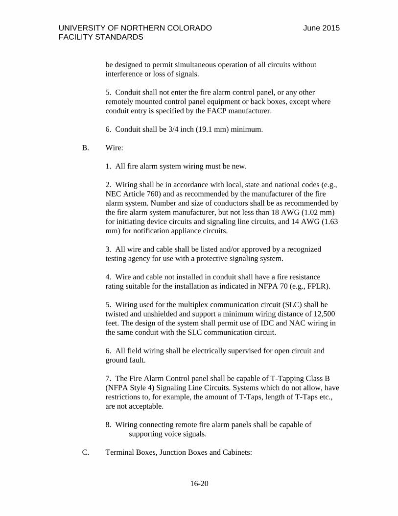
e. The system shall support a detector response time to meet world
annunciation requirements of less than 3 seconds.
f. Device Blink Control: Means shall be provided to turn off
detector/module LED strobes for special areas.
g. NFPA 72 Smoke Detector Sensitivity Test: The system shall
provide an automatic smoke detector test function that meets the
requirements of NFPA 72.
h. Programmable Trouble Reminder: The system shall provide
means to automatically initiate a reminder that troubles exist in the
system. The reminder will appear on the system display and (if
enabled) will sound a piezo alarm.
i. On-line or Off-line programming: The system shall provide
means to allow panel programming either through an off-line
software utility program away from the panel or while connected
and on-line. The system shall also support upload and download of
programmed database and panel executive system program to a
Personal Computer/laptop.
j. History Events: The panel shall maintain a history file of the last
4000 events, each with a time and date stamp. History events shall
include all alarms, troubles, operator actions, and programming
entries. The control panels shall also maintain a 1000 event Alarm
History buffer, which consists of the 1000 most recent alarm
events from the 4000 event history file.
k. Smoke Control Modes: The system shall provide means to
perform FSCS mode Smoke Control to meet NFPA-92A and 90B
and HVAC mode to meet NFPA 90A.
l. The system shall provide means for all SLC devices on any SLC
loop to be auto programmed into the system by specific address.
The system shall recognize specific device type ID's and associate
that ID with the corresponding address of the device.
m. Drill: The system shall support means to activate all silenceable
fire output circuits in the event of a practice evacuation or "drill". If
enabled for local control, the front panel switch shall be held for a
minimum of 2 seconds prior to activating the drill function
UNIVERSITY OF NORTHERN COLORADO June 2015 FACILITY STANDARDS
16-27
n. Passwords and Users: The system shall support two password
levels, master and user. Up to 9 user passwords shall be available,
each of which may be assigned access to the programming change
menus, the alter status menus, or both. Only the master password
shall allow access to password change screens.
o. Two Wire Detection: The system shall support standard two
wire detection devices specifically all models of System Sensor
devices.
p. Block Acknowledge: The system shall support a block
Acknowledge for Trouble Conditions
q. Sensitivity Adjust: The system shall provide Automatic Detector
Sensitivity Adjust based on Occupancy schedules including a
Holiday list of up to 15 days.
r. Environmental Drift Control: The system shall provide means for
setting Environmental Drift Compensation by device. When a
detector accumulates dust in the chamber and reaches an
unacceptable level but yet still below the allowed limit, the control
panel shall indicate a maintenance alert warning. When the
detector accumulates dust in the chamber above the allowed limit,
the control panel shall indicate a maintenance urgent warning.
s. Custom Action Messages: The system shall provide means to
enter up to 100 custom action messages of up to 160 characters
each. It shall be possible to assign any of the 100 messages to any
point.
t. Log Functions: The system shall provide means to log a variety
of reports listing all event, alarm, trouble, supervisory, or security
history. Additional reports shall be available for point activation
for the last Walk Test performed, detector maintenance report
containing the detector maintenance status of each installed
addressable detector, all network parameters, all panel settings
including broadcast time, event ordering, and block acknowledge,
panel timer values for Auto Silence, Silence Inhibit, AC Fail Delay
time and if enabled, Proprietary Reminder, and Remote Reminder
timers, supervision settings for power supply and printers, all
programmed logic equations, all custom action messages, all non-
fire and output activations (if pre-programmed for logging) all
active points filtered by alarms only, troubles only, supervisory
alarms, pre-alarms, disabled points and activated points, all

UNIVERSITY OF NORTHERN COLORADO June 2015 FACILITY STANDARDS
16-28
installed points filtered by SLC points, panel circuits, logic zones,
annunciators, releasing zones, special zones, and trouble zones.
u. Local Mode: If communication is lost to the central processor
the system shall provide added survivability through the intelligent
loop control modules. Inputs from devices connected to the SLC
and loop control modules shall activate outputs on the same loop
when the inputs and outputs have been set with point programming
to participate in local mode or when the type codes are of the same
type: that is, an input with a fire alarm type code shall activate an
output with a fire alarm type code.
v. Resound based on type for security or supervisory: The system
shall indicate a Security alarm when a monitor module point
programmed with a security Type Code activates. If silenced
alarms exist, a Security alarm will resound the panel sounder. The
system shall indicate a Supervisory alarm when a monitor module
point programmed with a supervisory Type Code activates. If there
are silenced alarms, a Supervisory alarm will resound the panel
sounder.
w. Read status preview - enabled and disabled points: Prior to re-
enabling points, the system shall inform the user that a disabled
device is in the alarm state. This shall provide notice that the
device must be reset before the device is enabled thereby avoiding
activation of the notification circuits.
x. Custom Graphics: When fitted with an LCD display, the panel
shall permit uploading of a custom bit-mapped graphic to the
display screen. Graphic shall display when all systems are normal.
y. Multi-Detector and Cooperating Detectors: The system shall
provide means to link one detector to up to two detectors at other
addresses on the same loop in cooperative multi-detector sensing.
There shall be no requirement for sequential addresses on the
detectors and the alarm event shall be a result or product of all
cooperating detectors chamber readings.
z. Tracking/Latching Duct (ion and photo): The system shall
support both tracking and latching duct detectors either ion or
photo types.
aa. ACTIVE EVENT: The system shall provide a Type ID called
FIRE CONTROL for purposes of air-handling shutdown, which

UNIVERSITY OF NORTHERN COLORADO June 2015 FACILITY STANDARDS
16-29
shall be intended to override normal operating automatic functions.
Activation of a FIRE CONTROL point shall cause the control
panel to (1) initiate the monitor module Control-by-Event, (2) send
a message to the panel display, history buffer, installed printer and
annunciators, (3) shall not light an indicator at the control panel,
(4) Shall display ACTIVE on the LCD as well a display a FIRE
CONTROL Type Code and other information specific to the
device.
bb. NON-FIRE Alarm Module Reporting: A point with a type ID
of NON-FIRE shall be available for use for energy management or
other non-fire situations. NON-FIRE point operation shall not
affect control panel operation nor shall it display a message at the
panel LDC. Activation of a NON-FIRE point shall activate control
by event logic but shall not cause any indication on the control
panel.
cc. Security Monitor Points: The system shall provide means to
monitor any point as a type security.
dd. One-Man Walk Test: The system shall provide both a basic
and advanced walk test for testing the entire fire alarm system.
The basic walk test shall allow a single operator to run audible
tests on the panel. All logic equation automation shall be
suspended during the test and while annunciators can be enabled
for the test, all shall default to the disabled state. During an
advanced walk test, field-supplied output point programming will
react to input stimuli such as CBE and logic equations. When
points are activated in advanced test mode, each initiating event
shall latch the input. The advanced test shall be audible and shall
be used for pull station verification, magnet activated tests on input
devices, input and output device and wiring operation/verification.
ee. Control By Event Functions: CBE software functions shall
provide means to program a variety of output responses based on
various initiating events. The control panel shall operate CBE
through lists of zones. A zone shall become listed when it is added
to a point's zone map through point programming. Each input point
such as detector, monitor module or panel circuit module shall
support listing of up to 10 zones into its programmed zone map.
ff. Permitted zone types shall be general zone, releasing zone and
special zone. Each output point (control module, panel circuit
module) can support a list of up to 10 zones including general

UNIVERSITY OF NORTHERN COLORADO June 2015 FACILITY STANDARDS
16-30
zone, logic zone, releasing zone and trouble zone. It shall be
possible for output points to be assigned to list general alarm.
Non-Alarm or Supervisory points shall not activate the general
alarm zone.
gg. 1000 General Zones: The system shall support up to 1000
general purpose software zones for linking inputs to outputs.
When an input device activates, any general zone programmed into
that device's zone map will be active and any output device that has
an active general zone in its map will be active. It shall also be
possible to use general zone as arguments in logic equations.
hh. 1000 Logic Equations: The system shall support up to 1000
logic equations for AND, OR, NOT, ONLY1, ANYX, XZONE or
RANGE operators that allow conditional I/O linking. When any
logic equation becomes true, all output points mapped to the logic
zone shall activate.
ii. Ten trouble equations per device: The system shall provide
support for up to 10 trouble equations for each device, which shall
permit programming parameters to be altered, based on specific
fault conditions. If the trouble equation becomes true, all output
points mapped to the trouble zone shall activate.
jj. Control-By-Time: A time based logic function shall be
available to delay an action for a specific period of time based
upon a logic input with tracking feature. A latched version shall
also be available. Another version of this shall permit activation
on specific days of the week or year with ability to set and restore
based on a 24 hour time schedule on any day of the week or year.
kk. Multiple agent releasing zones: The system shall support up to
10 releasing zones to protect against 10 independent hazards.
Releasing zones shall provide up to three cross-zones with four
abort options to satisfy any local jurisdiction requirements.
ll. Alarm Verification, by device, with timer and tally: The system
shall provide a user-defined global software timer function that can
be set for a specific detector or indicating panel module input. The
timer function shall delay an alarm signal for a user-specified time
period and the control panel shall ignore the alarm verification
timer if another alarm is detected during the verification period. It
shall also be possible to set a maximum verification count between
0 and 20 with the "0" setting producing no alarm verification.

UNIVERSITY OF NORTHERN COLORADO June 2015 FACILITY STANDARDS
16-31
When the counter exceeds the threshold value entered, a trouble
shall be generated to the panel.
E. Central Processing Unit
1. The Central Processing Unit shall communicate with, monitor, and
control all other modules within the control panel. Removal, disconnection
or failure of any control panel module shall be detected and reported to the
system display by the Central Processing Unit.
2. The Central Processing Unit shall contain and execute all control-by-
event (including Boolean functions including but not limited to AND, OR,
NOT, ANYx, and CROSSZONE) programs for specific action to be taken
if an alarm condition is detected by the system. Such control-by-event
programs shall be held in non-volatile programmable memory, and shall
not be lost with system primary and secondary power failure.
3. The Central Processing Unit shall also provide a real-time clock for
time annotation, to the second, of all system events. The time-of-day and
date shall not be lost if system primary and secondary power supplies fail.
4. The CPU shall be capable of being programmed on site without
requiring the use of any external programming equipment. Systems that
require the use of external programmers or change of EPROMs are not
acceptable.
5. Consistent with UL864 standards, the CPU and associated equipment
are to be protected so that voltage surges or line transients will not affect
them.
6. Each peripheral device connected to the CPU shall be continuously
scanned for proper operation. Data transmissions between the CPU and
peripheral devices shall be reliable and error free. The transmission
scheme used shall employ dual transmission or other equivalent error
checking techniques.
7. The CPU shall provide an EIA-232 interface between the fire alarm
control panel and the UL Listed Electronic Data Processing (EDP)
peripherals.
8. The CPU shall provide two EIA-485 ports for the serial connection to
annunciation and control subsystem components.

UNIVERSITY OF NORTHERN COLORADO June 2015 FACILITY STANDARDS
16-32
9. The EIA-232 serial output circuit shall be optically isolated to assure
protection from earth ground.
10. The CPU shall provide one high-speed serial connection for support
of network communication modules.
11. The CPU shall provide double pole relays for FIRE ALARM,
SYSTEM TROUBLE, SUPERVISORY, and SECURITY. The
SUPERVISORY and SECURITY relays shall provide selection for
additional FIRE ALARM contacts.
12. BACnet or LON interface devices will be provided as needed for
other control systems to interface with the fire alarm system.
13. A Honeywell system shall have a Fire Network Adapter (FNA) and a
Notifier system shall be provided with a BACnet Gateway card along with
an NFN-GW-EM-3 card for direct connection and transmission of fire
alarm signals to the UNC Honeywell EBi Server and the 2 Notifier
Onyxworks workstations located in the IT equipment Room Q1206 in
Gray Hall and the UNC Police dispatch desk in room 2206 Gray Hall.
14. All Notifier fire alarm panels require 2 CAT-6 data drops per panel.
F. Display
1. The system display shall provide all the controls and indicators used by
the system operator and may also be used to program all system
operational parameters.
2. The display assembly shall contain, and display as required, custom
alphanumeric labels for all intelligent detectors, addressable modules, and
software zones.
3. The system display shall provide a 640-character backlit alphanumeric
Liquid Crystal Display (LCD). It shall also provide ten Light-Emitting-
Diodes (LEDs) that indicate the status of the following system parameters:
AC POWER, FIRE ALARM, PREALARM, SECURITY,
SUPERVISORY, SYSTEM TROUBLE, OTHER EVENT, SIGNALS
SILENCED, POINT DISABLED, and CPU FAILURE.
4. The system display shall provide a QWERTY style keypad with control
capability to command all system functions, entry of any alphabetic or
numeric information, and field programming. Two different password
levels with up to ten (one Master and nine User) passwords shall be

UNIVERSITY OF NORTHERN COLORADO June 2015 FACILITY STANDARDS
16-33
accessible through the display interface assembly to prevent unauthorized
system control or programming.
5. The system display shall include the following operator control
switches: ACKNOWLEDGE, SIGNAL SILENCE, RESET, DRILL, and
LAMP TEST. Additionally, the display interface shall allow scrolling of
events by event type including, FIRE ALARM, SECURITY,
SUPERVISORY, TROUBLE, and OTHER EVENTS. A PRINT
SCREEN button shall be provided for printing the event currently
displayed on the 640-character LCD.
G. Loop (Signaling Line Circuit) Control Module:
1. The Loop Control Module shall monitor and control a minimum of 318
intelligent addressable devices. This includes 159 intelligent detectors
(Ionization, Photoelectric, or Thermal) and 159 monitor or control
modules.
2. The Loop Control Module shall contain its own microprocessor and
shall be capable of operating in a local/degrade mode (any addressable
device input shall be capable of activating any or all addressable device
outputs) in the unlikely event of a failure in the main CPU.
3. The Loop Control Module shall provide power and communicate with
all intelligent addressable detectors and modules on a single pair of wires.
This SLC Loop shall be capable of operating as a NFPA Style 4 (Class B)
circuit.
4. The SLC interface board shall be able to drive an NFPA Style 4 twisted
shielded circuit up to 12,500 feet in length. The SLC Interface shall also be
capable of driving an NFPA Style 4, no twist, no shield circuit up to 3,000
feet in length. In addition, SLC wiring shall meet the listing requirements
for it to exit the building or structure. "T"-tapping shall be allowed in
either case.
5. The SLC interface board shall receive analog or digital information
from all intelligent detectors and shall process this information to
determine whether normal, alarm, or trouble conditions exist for that
particular device. Each SLC Loop shall be isolated and equipped to
annunciate an Earth Fault condition. The SLC interface board software
shall include software to automatically maintain the detector's desired
sensitivity level by adjusting for the effects of environmental factors,
including the accumulation of dust in each detector. The analog

UNIVERSITY OF NORTHERN COLORADO June 2015 FACILITY STANDARDS
16-34
information may also be used for automatic detector testing and the
automatic determination of detector maintenance requirements.
H. Enclosures:
1. The control panel shall be housed in a UL-listed cabinet suitable for
surface or semi-flush mounting. The cabinet and front shall be corrosion
protected, given a rust-resistant prime coat, and manufacturer's standard
finish.
2. The back box and door shall be constructed of 0.060 steel with
provisions for electrical conduit connections into the sides and top.
3. The door shall provide a key lock and shall include a glass or other
transparent opening for viewing of all indicators. For convenience, the
door may be site configured for either right or left hand hinging.
4. The control unit shall be modular in structure for ease of installation,
maintenance, and future expansion.
I. Power Supply:
1. The Addressable Main Power Supply shall operate on 120/240 VAC,
50/60 Hz, and shall provide all necessary power for the FACP.
2. The Addressable Main Power Supply shall provide 9 amps of power to
the CPU, using a switching 24 VDC regulator and shall incorporate a
battery charger for 24 hours of standby power using dual-rate charging
techniques for fast battery recharge.
3. The Addressable Main Power Supply shall provide a battery charger for
24 hours of standby using dual-rate charging techniques for fast battery
recharge. The supply shall be capable of charging batteries ranging in
capacity from 25-200 amp-hours within a 48-hour period.
4. The Addressable Main Power Supply shall provide a very low
frequency sweep earth detect circuit, capable of detecting earth faults.
5. The Addressable Main Power Supply shall be power-limited per 1995
UL864 requirements.
J. Digital Voice Command

UNIVERSITY OF NORTHERN COLORADO June 2015 FACILITY STANDARDS
16-35
1. A Digital Voice Command System shall be available and integrated
into the fire alarm system. It shall have evacuation messaging, paging, and
fire fighter telephone capabilities for high-rise applications.
2. Shall have as minimum requirements:
a. Integral 25 Watt, 25 Vrms audio amplifier.
b. Speaker circuits that can be wired either Class A or B.
c. Integral Digital Message Generator with a capacity of up to 60
seconds. The Digital Message Generator shall be capable of
primary and secondary messages (30 seconds each). These
messages shall be field programmable without the use of additional
equipment.
d. Built in alert tone generators with steady, slow whoop, high/low
and chime tone field programmable.
e. Integral Diagnostic LEDs for Power, System Trouble, Message
Generator Trouble, Tone Generator Trouble, and Alarm.
4. The Voice Control Panel shall be fully supervised including
microphone, amplifier output, message generator, speaker wiring, and tone
generators.
5. Speaker outputs shall be fully power-limited.
K. Auxiliary Field Power Supply - Addressable
1. The auxiliary addressable power supply is a remote 24 VDC power
supply used to power Notification Devices and field devices that require
regulated 24VDC power. The power supply shall also include and charge
backup batteries.
2. The addressable power supply for the fire alarm system shall provide
up a minimum of 6.0 amps of 24 volt DC regulated power for Notification
Appliance Circuit (NAC) power or 5 amps of 24 volt DC general power.
The power supply shall have an additional .5 amp of 24 VDC auxiliary
power for use within the same cabinet as the power supply. It shall include
an integral charger designed to charge 7.0 - 25.0 amp hour batteries.
3. The addressable power supply shall provide four individually
addressable Notification Appliance Circuits that may be configured as two

UNIVERSITY OF NORTHERN COLORADO June 2015 FACILITY STANDARDS
16-36
Class "A" and two Class "B" or four Class "B" only circuits. All circuits
shall be power-limited per UL 864 requirements.
4. The addressable power supply shall provide built-in synchronization for
certain Notification Appliances on each circuit without the need for
additional synchronization modules. The power supply's output circuits
shall be individually selected for synchronization. A single addressable
power supply shall be capable of supporting both synchronized and non-
synchronized Notification Devices at the same time.
5. The addressable power supply shall operate on 120 or 240 VAC, 50/60
Hz.
6. The interface to the power supply from the Fire Alarm Control Panel
(FACP) shall be via the Signaling Line Circuit (SLC) or other multiplexed
means. Power supplies that do not use an intelligent interface are not
suitable substitutes. The required wiring from the FACP to the
addressable power supply shall be a single unshielded twisted pair wire.
7. The addressable power supply shall supervise for battery charging
failure, AC power loss, power brownout, battery failure, NAC loss, and
optional ground fault detection. In the event of a trouble condition, the
addressable power supply shall report the incident and the applicable
address to the FACP via the SLC.
8. The addressable power supply shall have an AC Power Loss Delay
option. If this option is utilized and the addressable power supply
experiences an AC power loss, reporting of the incident to the FACP will
be delayed. A delay time of eight or sixteen hours shall be Dip-switch
selected.
9. The addressable power supply mounts in either the FACP back box or
its own dedicated surface mounted back box with cover.
10. Each of the power supply's four output circuits shall be DIP-switch
selected for Notification Appliance Circuit or General Purpose 24 VDC
power. Any output circuit shall be able to provide up to 2.5 amps of 24
VDC power.
11. The addressable power supply's output circuits shall be individually
supervised when they are selected to be either a Notification Appliance
Circuit when wired Class "A" or by the use of and end-of-line resistor.
When the power supply's output circuit is selected as General 24VDC

UNIVERSITY OF NORTHERN COLORADO June 2015 FACILITY STANDARDS
16-37
power, the circuit shall be individually supervised when an end-of-line
relay is used.
12. When selected for Notification Appliance Circuits, the output circuits
shall be individually DIP-switch selectable for Steady, March Time, Dual
Stage or Temporal.
13. When selected as a Notification Appliance Circuit, the output circuits
of the addressable power supply shall have the option to be coded by the
use of a universal zone coder.
14. The addressable power supply shall interface and synchronize with
other power supplies of the same type. The required wiring to interface
multiple addressable power supplies shall be a single unshielded, twisted
pair wire.
15. An individual or multiple interfaced addressable power supplies shall
have the option to use an external charger for battery charging. Interfaced
power supplies shall have the option to share backup battery power.
L. Field Charging Power Supply: The FCPS is a device designed for use as
either a remote 24 volt power supply or to power Notification Appliances
and provide synchronization signals to visual strobe devices.
1. The FCPS shall be available in two models offering either up to 6.0
amps (4.0 amps continuous) or 8.0 amps (6.0 amps continuous) of
regulated 24-volt power. It shall include an integral charger designed to
charge 7.0 amp hour batteries and to support 60-hour standby.
2. The Field Charging Power Supply shall have two input triggers. The
input trigger shall be a Notification Appliance Circuit (from the fire alarm
control panel) or a relay. Four outputs (two Style Y or Z and two style Y)
shall be available for connection to the Notification devices.
3. The FCPS shall include an attractive surface mount back box.
4. The Field Charging Power Supply shall include the ability to delay the
AC fail delay per NFPA requirements.
5. The FCPS include power limited circuitry, per 1995 UL standards.
M. System Circuit Supervision:

UNIVERSITY OF NORTHERN COLORADO June 2015 FACILITY STANDARDS
16-38
1. The FACP shall supervise all circuits to intelligent devices,
annunciators and conventional peripherals and annunciate loss of
communications with these devices. The CPU shall continuously scan
above devices for proper system operation and upon loss of response from
a device shall sound an audible trouble, indicate that device or devices are
not responding and print the information in the history buffer and on a
printer.
2. Sprinkler system valves, standpipe control valves, PIV and main gate
valves shall be supervised for off-normal position.
N. Field Wiring Terminal Blocks: All wiring terminal blocks shall be
the plug-in/removable type and shall be capable of terminating up to 12
AWG wire. Terminal blocks that are permanently fixed to the PC board
are not acceptable.
O. System Expansion: Design the main FACP so that the system can be
expanded in the future (to include the addition of twenty percent more
circuits or zones) without disruption or replacement of the existing control
panel. This shall include hardware capacity, software capacity and cabinet
space.
P. Field Programming
1. The system shall be programmable, configurable and expandable in the
field without the need for special tools, laptop computers, or other
electronic interface equipment. There shall be no firmware changes
required to field modify the system time, point information, equations, or
annunciator programming/information.
2. It shall be possible to program through the standard FACP keyboard all
system functions.
3. All field defined programs shall be stored in non-volatile memory.
4. Two levels of password protection shall be provided in addition to a
key-lock cabinet. One level shall be used for status level changes such as
point/zone disable or manual on/off commands (Building Manager). A
second (higher-level) shall be used for actual change of the life safety
program (installer). These passwords shall be five (5) digits at a minimum.
Upon entry of an invalid password for the third time within a one minute
time period an encrypted number shall be displayed. This number can be
used as a reference for determining a forgotten password.

UNIVERSITY OF NORTHERN COLORADO June 2015 FACILITY STANDARDS
16-39
5. The system programming shall be "backed" up on a CD ROM utilizing
an upload/download program. This system back-up disk shall be
completed and given in duplicate to the building owner and/or operator
upon completion of the final inspection. The program that performs this
function shall be "non-proprietary", in that, it shall be possible to forward
it to the building owner/operator upon his or her request.
Q. The installer's field programming and hardware shall be functionally tested
on a computer against known parameters/norms which are established by
the FACP manufacturer. A software program shall test Input-to-Output
correlations, device Type ID associations, point associations, time
equations, etc. This test shall be performed on an IBM-compatible PC
with a verification software package. A report shall be generated of the
test results and two copies turned in to the engineer(s) on record.
R. It shall be the responsibility of the equipment supplier /installer to ensure
that all equipment supplied will fit in locations designated on plans and in
the specifications.
S. Specific System Operations
1. Smoke Detector Sensitivity Adjust: Means shall be provided for
adjusting the sensitivity of any or all analog intelligent smoke detectors in
the system from the system keypad or from the keyboard of the video
terminal. Sensitivity range shall be within the allowed UL window.
2. Alarm Verification: Each of the Intelligent Addressable Smoke
Detectors in the system may be independently selected and enabled to be
an alarm verified detector. The alarm verification function shall be
programmable from 5 to 50 seconds and each detector shall be able to be
selected for verification during the field programming of the system or
anytime after system turn-on. Alarm verification shall not require any
additional hardware to be added to the control panel. The FACP shall keep
a count of the number of times that each detector has entered the
verification cycle. These counters may be displayed and reset by the proper
operator commands.
3. System Point Operations:
a. Any addressable device in the system shall have the capability to
be enabled or disabled through the system keypad or video
terminal.

UNIVERSITY OF NORTHERN COLORADO June 2015 FACILITY STANDARDS
16-40
b. System output points shall be capable of being turned on or off
from the system keypad or the video terminal.
4. Point Read: The system shall be able to display the following point
status diagnostic functions without the need for peripheral equipment.
Each point shall be annunciated for the parameters listed:
a. Device Status.
b. Device Type.
c. Custom Device Label.
d. Software Zone Label.
e. Device Zone Assignments.
f. Analog Detector Sensitivity.
g. All Program Parameters.
5. System Status Reports: Upon command from an operator of the system,
a status report will be generated listing all system statuses:
6. System History Recording and Reporting: The fire alarm control panel
shall contain a history buffer that will be capable of storing up to 4000
system events. Each of these events will be stored, with time and date
stamp, until an operator requests that the contents be displayed. The
contents of the history buffer may be manually reviewed, one event at a
time, and the actual number of activations may also be displayed. The
history buffer shall use non-volatile memory. Systems that use volatile
memory for history storage are not acceptable.
7. Automatic Detector Maintenance Alert: The fire alarm control panel
shall automatically interrogate each intelligent system detector and shall
analyze the detector responses over a period of time. If any intelligent
detector in the system responds with a reading that is below or above
normal limits, then the system will enter the trouble mode, and the
particular Intelligent Detector will be annunciated on the system display.
This feature shall in no way inhibit the receipt of alarm conditions in the
system, nor shall it require any special hardware, special tools or computer
expertise to perform.
8. The system shall include the ability (programmable) to indicate a "pre-
alarm" condition. This will be used to alert maintenance personal when a
detector is at 80% of its alarm threshold in a 60 second period.
2.5. SYSTEM COMPONENTS:
A. Programmable Electronic Sounders:

UNIVERSITY OF NORTHERN COLORADO June 2015 FACILITY STANDARDS
16-41
1. Electronic sounders shall operate on 24 VDC nominal.
2. Electronic sounders shall be field programmable without the use of
special tools, at a sound level of at least 102 dBA measured at 10 feet from
the device.
3. Shall be flush or surface mounted as shown on plans.
4. All speakers shall operate on 25 VRMS or with not less than 4 field
selectable output taps from 0.5 to 2.0 Watts.
5. Speakers in corridors and public spaces shall produce a nominal sound
output of 84 dBA at 10 feet (3m).
6. Speakers shall be suitable for voice communication and tone signals
with frequency response that is flat within 3 dB between 400 HZ to 4000
HZ.
7. The back of each speaker shall be sealed to protect the speaker cone
from damage and dust.
B. Strobe lights shall meet the requirements of the ADA, UL Standard 1971,
be fully synchronized, and shall meet the following criteria:
1. The maximum pulse duration shall be 2/10 of one second.
2. Strobe intensity shall meet the requirements of UL 1971.
3. The flash rate shall meet the requirements of UL 1971.
C. Audible/Visual Combination Devices:
1. Shall meet the applicable requirements of Section A listed above for
audibility.
2. Shall meet the requirements of Section B listed above for visibility.
D. Addressable Devices - General
1. Addressable devices shall provide an address-setting means using
rotary decimal switches.

UNIVERSITY OF NORTHERN COLORADO June 2015 FACILITY STANDARDS
16-42
2. Addressable devices shall use simple to install and maintain decade
(numbered 0 to 9) type address switches. Devices which use a binary
address or special tools for setting the device address, such as a dip switch
are not an allowable substitute.
3. Detectors shall be analog and addressable, and shall connect to the fire
alarm control panel's Signaling Line Circuits.
4. Addressable smoke and thermal detectors shall provide dual (2) status
LEDs. Both LEDs shall flash under normal conditions, indicating that the
detector is operational and in regular communication with the control
panel, and both LEDs shall be placed into steady illumination by the
control panel, indicating that an alarm condition has been detected. If
required, the flashing mode operation of the detector LEDs can be
programmed off via the fire control panel program.
5. The fire alarm control panel shall permit detector sensitivity adjustment
through field programming of the system. Sensitivity can be automatically
adjusted by the panel on a time-of-day basis.
6. Using software in the FACP, detectors shall automatically compensate
for dust accumulation and other slow environmental changes that may
affect their performance. The detectors shall be listed by UL as meeting
the calibrated sensitivity test requirements of NFPA Standard 72, Chapter
7.
7. The detectors shall be ceiling-mount and shall include a separate twist-
lock base which includes a tamper proof feature.
8. The following bases and auxiliary functions shall be available:
a. Sounder base rated at 85 DBA minimum.
b. Form-C Relay base rated 30VDC, 2.0A
c. Isolator base
9. The detectors shall provide a test means whereby they will simulate an
alarm condition and report that condition to the control panel. Such a test
may be initiated at the detector itself (by activating a magnetic switch) or
initiated remotely on command from the control panel.

UNIVERSITY OF NORTHERN COLORADO June 2015 FACILITY STANDARDS
16-43
10. Detectors shall also store an internal identifying type code that the
control panel shall use to identify the type of device (ION, PHOTO,
THERMAL).
E. Addressable Pull Box (manual station)
1. Addressable pull boxes shall, on command from the control panel, send
data to the panel representing the state of the manual switch and the
addressable communication module status. They shall use a key operated
test-reset lock, and shall be designed so that after actual emergency
operation, they cannot be restored to normal use except by the use of a
key.
2. All operated stations shall have a positive, visual indication of operation
and utilize a key type reset.
3. Manual stations shall be constructed of Lexan with clearly visible
operating instructions provided on the cover. The word FIRE shall appear
on the front of the stations in raised letters, 1.75 inches (44 mm) or larger.
4. Manual pull stations shall be protected from accidental activation and/or
physical damage by use of a STI ™ “Stopper II” cover.
F. Intelligent Photoelectric Smoke Detector
1. The detectors shall use the photoelectric (light-scattering) principal to
measure smoke density and shall, on command from the control panel,
send data to the panel representing the analog level of smoke density.
G. Intelligent Ionization Smoke Detector
1. Not an acceptable means of detection.
H. Intelligent Multi Criteria Acclimating Detector
1. The intelligent multi criteria Acclimate detector shall be an addressable
device that is designed to monitor a minimum of photoelectric and thermal
technologies in a single sensing device. The design shall include the
ability to adapt to its environment by utilizing a built-in microprocessor to
determine it's environment and choose the appropriate sensing settings.
The detector design shall allow a wide sensitivity window, no less than 1
to 4% per foot obscuration. This detector shall utilize advanced
electronics that react to slow smoldering fires and thermal properties all
within a single sensing device.

UNIVERSITY OF NORTHERN COLORADO June 2015 FACILITY STANDARDS
16-44
2. The microprocessor design shall be capable of selecting the appropriate
sensitivity levels based on the environment type it is in (office,
manufacturing, kitchen etc.) and then have the ability to automatically
change the setting as the environment changes (as walls are moved or as
the occupancy changes).
3. The intelligent multi criteria detection device shall include the ability to
combine the signal of the thermal sensor with the signal of the
photoelectric signal in an effort to react hastily in the event of a fire
situation. It shall also include the inherent ability to distinguish between a
fire condition and a false alarm condition by examining the characteristics
of the thermal and smoke sensing chambers and comparing them to a
database of actual fire and deceptive phenomena.
I. Intelligent Thermal Detectors
1. Thermal detectors shall be intelligent addressable devices rated at 135
degrees Fahrenheit (58 degrees Celsius) and have a rate-of-rise element
rated at 15 degrees F (9.4 degrees C) per minute. It shall connect via two
wires to the fire alarm control panel signaling line circuit.
J. Intelligent Duct Smoke Detector
1. The smoke detector housing shall accommodate an intelligent
photoelectric detector, that provides continuous analog monitoring and
alarm verification from the panel. Provide an extra Form C contact for
direct fan shutdown.
2. When sufficient smoke is sensed, an alarm signal is initiated at the
FACP, and appropriate action taken to change over air handling systems to
help prevent the rapid distribution of toxic smoke and fire gases
throughout the areas served by the duct system.
K. Hostile-Area Smoke Detector
1. The detector shall be designed to provide early warning smoke
detection in environments where traditional smoke detectors are not
practical.
2. The detector shall have a filter system to remove particles down to 25
microns.

UNIVERSITY OF NORTHERN COLORADO June 2015 FACILITY STANDARDS
16-45
3. This filter system shall remove unwanted airborne particles and water
mist. This shall allow the detector to operate in environments where
traditional smoke detectors would have nuisance alarms.
4. The filter system shall consist of 2 filters one of which is field
replaceable.
5. The filter system shall have an intake fan to draw air and smoke
through the filters into the sensing chamber.
6. The filter system shall be supervised so that if the filter is clogged or
the fan fails the control panel reports trouble.
7. The filter system shall be powered from 24 VDC separate from the
SLC communications.
8. The detector shall utilize a photoelectric sensing chamber.
L. Addressable Dry Contact Monitor Module
1. Addressable monitor modules shall be provided to connect one
supervised IDC zone of conventional alarm initiating devices (any N.O.
dry contact device) to one of the fire alarm control panel SLCs.
2. The monitor module shall mount in a 4-inch square (101.6 mm square),
2-1/8 inch (54 mm) minimum depth electrical box.
3. The IDC zone shall be suitable for Style D or Style B operation. An
LED shall be provided that shall flash under normal conditions, indicating
that the monitor module is operational and in regular communication with
the control panel.
4. For difficult to reach areas, the monitor module shall be available in a
miniature package and shall be no larger than 2-3/4 inch (70 mm) x 1-1/4
inch (31.7 mm) x 1/2 inch (12.7 mm). This version need not include Style
D or an LED.
M. Two Wire Detector Monitor Module
1. Addressable monitor modules shall be provided to connect one
supervised IDC zone of conventional 2-wire smoke detectors or alarm
initiating devices (any N.O. dry contact device).

UNIVERSITY OF NORTHERN COLORADO June 2015 FACILITY STANDARDS
16-46
2. The two-wire monitor module shall mount in a 4-inch square (101.6
mm square), 2-1/8 inch (54 mm) minimum deep electrical box or with an
optional surface back box.
3. The IDC zone shall be wired for Class B (Style B) operation. An LED
shall be provided that shall flash under normal conditions, indicating that
the monitor module is operational and in regular communication with the
control panel.
N. Addressable Control Module
1. Addressable control modules shall be provided to supervise and control
the operation of one conventional NACs of compatible, 24 VDC powered
polarized audio/visual notification appliances. For fan shutdown and other
auxiliary control functions, the control module may be set to operate as a
dry contact relay.
2. The control module shall mount in a standard 4-inch square (101.6 mm
square), 2-1/8 inch (54 mm) minimum deep electrical box, or to a surface
mounted back box.
3. The control module NAC shall be wired for Style Y (Class B) with up
to 1 amp of inductive A/V signal, or 2 amps of resistive A/V signal
operation, or as a dry contact (Form-C) relay. The relay coil shall be
magnetically latched to reduce wiring connection requirements, and to
insure that 100% of all auxiliary relay or NACs may be energized at the
same time on the same pair of wires.
4. Audio/visual power shall be provided by a separate supervised power
circuit from the main fire alarm control panel or from a supervised, UL
listed remote power supply.
5. The control module shall be suitable for pilot duty applications and
rated for a minimum of 0.6 amps at 30 VDC.
O. Addressable Relay Module
1. Addressable Relay Modules shall be available for HVAC control and
other building functions. The relay shall be form C and rated for a
minimum of 2.0 Amps resistive or 1.0 Amps inductive. The relay coil
shall be magnetically latched to reduce wiring connection requirements,
and to insure that 100% of all auxiliary relay or NACs may be energized at
the same time on the same pair of wires.

UNIVERSITY OF NORTHERN COLORADO June 2015 FACILITY STANDARDS
16-47
P. Custom Point Graphic Annunciator Requirements
1. The annunciator will have an "ON-LINE" LED, local piezo sounder,
local acknowledge, lamp test and reset switches and custom floor plan
graphics to show where alarm conditions are present as shown with
LED’s.
2. The annunciator may be field configured to operate as a "Smoke
Control Annunciator" when needed. When configured as "Fan Control,"
the annunciator may be used to manually control fan or damper operation
and can be set to override automatic commands to all fans/dampers
programmed to the annunciator.
R. Water flow Indicators:
1. Waterflow Switches shall be an integral, mechanical, non-coded, non-
accumulative retard type.
2. Water flow Switches shall have an alarm transmission delay time
which is conveniently adjustable from 0 to 60 seconds. Initial settings shall
be 30-45 seconds.
3. All water flow switches shall come from a single manufacturer and
series.
4. Water flow switches shall be provided and connected under this section
but installed by the mechanical contractor.
5. Where possible, locate water flow switches a minimum of one (1) foot
from a fitting which changes the direction of the flow and a minimum of
three (3) feet from a valve.
S. Sprinkler and Standpipe Valve Supervisory Switches:
1. Each sprinkler system water supply control valve riser, zone control
valve, and standpipe system riser control valve shall be equipped with a
supervisory switch. Standpipe hose valves, and test and drain valves shall
not be equipped with supervisory switches.
2. PIV (post indicator valve) or main gate valves shall be equipped with a
supervisory switch.

UNIVERSITY OF NORTHERN COLORADO June 2015 FACILITY STANDARDS
16-48
3. The switch shall be mounted so as not to interfere with the normal
operation of the valve and adjusted to operate within two revolutions
toward the closed position of the valve control, or when the stem has
moved no more than one-fifth of the distance from its normal position.
4. The supervisory switch shall be contained in a weatherproof aluminum
housing, which shall provide a 3/4 inch (19 mm) conduit entrance and
incorporate the necessary facilities for attachment to the valves.
5. The switch housing shall be finished in red baked enamel.
6. The entire installed assembly shall be tamper proof and arranged to
cause a switch operation if the housing cover is removed, or if the unit is
removed from its mounting.
7. Valve supervisory switches shall be provided and connected under this
section and installed by the mechanical contractor.
2.6. BATTERIES AND EXTERNAL CHARGER:
A. Battery:
1. Shall be 12 volt, Gel-Cell type.
2. Battery shall have sufficient capacity to power the fire alarm system for
not less than twenty-four hours of standby plus 15 minutes of alarm upon a
normal AC power failure.
3. The batteries are to be completely maintenance free. No liquids are
required. Fluid level checks refilling, spills and leakage shall not be
required.
B. External Battery Charger:
1. Shall be completely automatic, with constant potential charger
maintaining the battery fully charged under all service conditions. Charger
shall operate from a 120/240-volt 50/60 hertz source.
2. Shall be rated for fully charging a completely discharged battery within
48 hours while simultaneously supplying any loads connected to the
battery.
3. Shall have protection to prevent discharge through the charger.

UNIVERSITY OF NORTHERN COLORADO June 2015 FACILITY STANDARDS
16-49
4. Shall have protection for overloads and short circuits on both AC and
DC sides.
2.7. NETWORK INTERFACE
A. A Honeywell FACP shall be provided with a Fire Network Adapter card
and a Notifier FACP shall be provided with a BACnet Gateway card along
with an NFN-GW-EM-3 card for interface with the existing Honeywell
EBi network server and the Notifier Onyxworks workstations located in
the Gray Hall IT equipment room Q1206 and the UNC Police dispatch
desk in room 2206 Gray Hall.
PART 3.0 – EXECUTION
3.1. INSTALLATION:
A. Installation shall be in accordance with the NEC, NFPA 72, local and state
codes, as shown on the drawings, and as recommended by the major equipment
manufacturer.
B. All conduit, junction boxes, conduit supports and hangers shall be
concealed in finished areas and may be exposed in unfinished areas. Smoke
detectors shall not be installed prior to the system programming and test period. If
construction is ongoing during this period, measures shall be taken to protect
smoke detectors from contamination and physical damage.
C. All fire detection and alarm system devices, control panels and remote
annunciators shall be flush mounted when located in finished areas and may be
surface mounted when located in unfinished areas.
D. The Honeywell factory trained technician in the event of a Honeywell system
installation or the Notifier factory trained technician in the event of a Notifier
system installation, shall provide and install data, programming and graphics at
the Honeywell EBi server in the event of a Honeywell system or the Notifier
Onyxworks workstations in the event of a Notifier system. The Honeywell EBI
server and one of the Notifier workstations are located in the Gray Hall IT
equipment Room Q1206 and the other Notifier workstation located in the UNC
police dispatch desk in Room 2206. Include distribution of monitoring, control
and security profiles as requested by owner, area diagrams, floor plans, key plans,
key maps and screen titles, auto-navigations criteria, and guidance text including
alarm messages as indicated by the owner.

UNIVERSITY OF NORTHERN COLORADO June 2015 FACILITY STANDARDS
16-50
3.2. TYPICAL OPERATION:
A. Except for resident living areas, actuation of any manual station, smoke
detector, heat detector or sprinkler water flow switch shall cause the following
operations to occur unless otherwise specified:
1. Activate all audible notification appliance circuits until silenced.
2. Activate all visual notification appliance circuits until the panel is reset.
3. Annunciate the active initiating devices and zones at the FACP and
graphic annunciator.
.
4. Release all magnetic door holders on doors leading to adjacent zones
on the floor from which the alarm was initiated.
5. A smoke detector in any elevator lobby shall, in addition to the above
functions, return all elevators to the primary or alternate floor of egress.
6. Smoke detectors in the elevator machine room or top of hoist way shall
return all elevators in to the primary or alternate floor of egress. Smoke
detectors or heat detectors installed to shut down elevator power shall do
so in accordance with ANSI A17.1 requirements and be coordinated with
the electrical contractor.
7. Duct type smoke detectors shall produce a “supervisory” alarm signal
at the FACP and shut down the ventilation system or close associated
control dampers as appropriate.
8. Activation of any sprinkler system low air pressure switch or valve
tamper switch shall cause a system supervisory alarm indication at the
FACP.
B. Actuation of any Resident Living area (student dorm room) smoke
detector shall cause the following operations to occur unless otherwise
specified:
1. Activate the audible sounder base(s) in the unit where the alarm is
initiated.
2. Activate the visual ADA notification appliances in the unit where the
alarm is initiated.

UNIVERSITY OF NORTHERN COLORADO June 2015 FACILITY STANDARDS
16-51
3. Annunciate the active initiating devices and zones at the FACP and
graphic annunciator.
C. HVAC/Smoke Control System Operation:
1. On/Auto/Off switches and status indicators (LEDS) shall be provided
for monitoring and manual control of each fan, damper, HVAC control
unit, stairwell pressurization fan, and smoke exhaust fan. To ensure
compliance the units supplied shall meet the following UL categories:
UUKL, PAZX, UDTZ, QVAX as well as the requirements of NFPA 90A,
HVAC, and NFPA 92A & 92B, Smoke Control. The control System shall
be field programmable for either 90A operation or 92A/B operation to
allow for future use and system expansion.
2. The OFF LED shall be Yellow, the ON LED shall be green, the
Trouble/Fault LED shall be Amber/Orange for each switch. The
Trouble/Fault indicator shall indicate a trouble in the control and/or
monitor points associated with that switch. In addition, each group of eight
switches shall have two LEDS and one momentary switch which allow the
following functions: An Amber LED to indicate an OFF-NORMAL switch
position, in the ON or OFF position; A Green LED to indicate ALL
AUTO switch position; A Local Acknowledge/Lamp Test momentary
switch.
3. Each switch shall have the capability to monitor and control two
addressable inputs and two addressable outputs. In all modes, the ON and
OFF indicators shall continuously follow the device status not the switch
position. Positive feedback shall be employed to verify correct operation
of the device being controlled. Systems that indicate on/off/auto by
physical switch position only are not acceptable.
4. All HVAC switches (i.e., limit switches, vane switches, etc.) shall be
provided and installed by the HVAC contractor.
5. It shall be possible to meet the requirements mentioned above utilizing
wall mounted custom graphic annunciators if the project requires such.
3.3. TEST:
Provide the service of a competent, factory-trained engineer or technician
authorized by the manufacturer of the fire alarm equipment to technically
supervise and participate during all of the adjustments and tests for the system.

UNIVERSITY OF NORTHERN COLORADO June 2015 FACILITY STANDARDS
16-52
1. Before energizing the cables and wires, check for correct connections
and test for short circuits, ground faults, continuity, and insulation integrity
with a “megger” type insulation tester.
2. Close each sprinkler system flow valve and verify proper supervisory
alarm at the FACP.
3. Verify activation of all sprinkler water flow switches.
4. Open initiating device circuits and verify that the trouble signal actuates
at the FACP.
5. Open signaling line circuits and verify that the trouble signal actuates at
the FACP.
6. Open and short notification appliance circuits and verify that trouble
signal actuates at the FACP.
7. Ground initiating device circuits and verify response of trouble signals
at the FACP.
8. Ground signaling line circuits and verify response of trouble signals at
the FACP.
9. Ground notification appliance circuits and verify response of trouble
signals at the FACP.
10. Check presence and audibility of tone at all alarm notification devices.
11. Check installation, supervision, and operation of all intelligent smoke
detectors during a walk test.
12. Each of the alarm conditions that the system is required to detect shall
be introduced on the system. Verify the proper receipt and processing of
the signals at the FACP and the two Honeywell EBi Workstations, one at
Parsons Hall BAS office 1147 and one at Gray Hall located in the police
department dispatch center in room 2206 and the Notifier Onyxworks
workstations in Gray Hall IT equipment Room Q1206 and the UNC
police dispatch desk in room 2206 Gray Hall and the correct activation of
the associated control points.
13. When the system is equipped with optional features, the
manufacturer’s manual should be consulted to determine the proper testing
procedures. This is intended to address such items as verifying controls

UNIVERSITY OF NORTHERN COLORADO June 2015 FACILITY STANDARDS
16-53
performed by individually addressed or grouped devices, sensitivity
monitoring, verification functionality and similar.
3.4. FINAL INSPECTION:
At the final inspection a factory trained representative of the manufacturer of the
major equipment shall demonstrate that the systems function properly in every
respect including alarm /trouble transmission to the UNC monitoring workstations
in the presence of the AHJ, Owner’s Representative, and General Contractor.
3.5. INSTRUCTION:
A. Provide a more general on site training and hands-on demonstration of the
operation of all system components for all personnel at the site.
B. The contractor and/or the systems manufacturer’s representatives shall
provide a typewritten “Sequence of Operation.”
-END OF SECTION 16721-
CLOCK SYSTEM
In general, clock systems are not require. If required for the facility, provide surface mounted, 110 V, 12” diameter wall clocks. Specify units that do not require any disassembly to adjust time.
TELECOMMUNICATIONS / VIDEO
Telecommunications requirements are constantlly increasing on campus. Please allow adequate space for addition of future equipment in the telecommunications room. Refer to the specific requirements in Division one.
Telecommunications requirements for telephone and data have been defined by the University Information Services Division. Refer to the appendix. Generally all areas will require wiring for both voice and data. Installation will also include any required outside plant extensions to the main telephone switch in Gray Hall as well as to the data backbone at locations to be determined.
UNIVERSITY OF NORTHERN COLORADO June 2015 FACILITY STANDARDS
16-54
Telecommunications requirements for classroom video service will be defined by the University.
Connection to the tunnel cable TV system is to be coordinated with UNC Information Technology. Television service on campus is currently provided by Campus Televideo. All television wiring is to be included in the project requirements. Electronics will be provided by UNC.
Closed circuit television requirements will be determined by the University but are to be included in the project scope.
A 3/4" plywood backboard shall be provided for mounting of the telecommunications equipment. Backboard shall be located in a secure area as defined by Facilities Management. Provide a 4 plex grounded outlet and a separate grounding conductor at the backboard.
Generally, each telephone, data or video outlet location will require a 4" x 4" box with single gang mud ring, 3/4" conduit stubbed up into the ceiling space. Coordinate specific design requirements with Facilities Management.
Provide a minimum of 2 –4” empty conduits from the telecommunications system backboard to the campus tunnel system.
All classrooms shall have at least one telephone, data and video jack located near the instructors station.
Requirements for CCTV systems will be determined for each project. CAMPUS EMERGENCY PHONES
Campus emergency phones shall be GAI – TRONICS #234 Stanchion, # 530B Beacon/Strobe, Blue Lamp and # 297 Emergency flush mount telephone. Provide speaker unit compatible with phone poles.
NOTE: Custom Color poles and luminaries to be RAL 5003 Sapphire blue powder coat..
CARD ACCESS SYSTEM
The University has installed a proprietary card access system for most buildings on campus. Design shall include a raceway and wiring system from

UNIVERSITY OF NORTHERN COLORADO June 2015 FACILITY STANDARDS
16-55
each exterior door to the main telephone equipment room for connection to the card system.
Power should also be provided to each exterior door for powered locking devices as well as automatic door operators.
Exterior conduit will need to be provided for push buttons controlling the handicapped operators, card readers and proximity devices tied to the card system.
Coordinate with the door hardware requirements in Division 8.
Refer to the attached card system specification in the appendix. COMMISSIONING
Specify General Contractor led commissioning of all mechanical, plumbing, controls and electrical systems to verify operational and functional performance and compliance with “design intent”.
Coordinate commissioning requirements with other divisions as needed.
All system tests and inspections are to be full documented.
Complete commissioning of mechanical and electrical systems during initial start-up
Provide advance notice to UNC Facilities Management prior to all commissioning activities.
Contractor to submit for review, an outline of the organizational plan, commissioning schedule, documentation process and commissioning plan specific to the project.
Establish the requirements and plan for the commissioning process throughout the construction phase of the project.
Commissioning shall begin after equipment and systems are complete. Include:

UNIVERSITY OF NORTHERN COLORADO June 2015 FACILITY STANDARDS
16-56
Review and verification of TAB readings
Verify calibration of thermostats and related controls
Verify readings of remote data and control systems
Verify operation of system modes
Verify that total system is performing to provide conditions as outlined in the contract documents.