Embed Size (px)
Citation preview

University of Dundee
On solitary wave diffraction by multiple, in-line vertical cylinders
Neill, Douglas R.; Hayatdavoodi, Masoud; Ertekin, R. Cengiz
Published in:Nonlinear Dynamics
DOI:10.1007/s11071-017-3923-1
Publication date:2018
Document VersionPeer reviewed version
Link to publication in Discovery Research Portal
Citation for published version (APA):Neill, D. R., Hayatdavoodi, M., & Ertekin, R. C. (2018). On solitary wave diffraction by multiple, in-line verticalcylinders. Nonlinear Dynamics, 91(2), 975-994. https://doi.org/10.1007/s11071-017-3923-1
General rightsCopyright and moral rights for the publications made accessible in Discovery Research Portal are retained by the authors and/or othercopyright owners and it is a condition of accessing publications that users recognise and abide by the legal requirements associated withthese rights.
• Users may download and print one copy of any publication from Discovery Research Portal for the purpose of private study or research. • You may not further distribute the material or use it for any profit-making activity or commercial gain. • You may freely distribute the URL identifying the publication in the public portal.
Take down policyIf you believe that this document breaches copyright please contact us providing details, and we will remove access to the work immediatelyand investigate your claim.
Download date: 27. Nov. 2021

Author
acce
pted m
anus
cript
Not co
pyed
ited b
y the
journ
al
Nonlinear Dynamics manuscript No.(will be inserted by the editor)
On Solitary Wave Diffraction by Multiple, In-line
Vertical Cylinders
Douglas R. Neill
Masoud Hayatdavoodi
R. Cengiz Ertekin
Received: date / Accepted: date
Abstract The interaction of solitary waves with multiple, in-line vertical
cylinders is investigated. The fixed cylinders are of constant circular cross-
section and extend from the sea floor to the free surface. In general, there are
N of them lined in a row parallel to the incoming wave direction. Both the non-
linear, generalized Boussinesq and the Green-Naghdi shallow-water wave equa-
tions are used. A boundary-fitted curvilinear coordinate system is employed
to facilitate the use of the finite-difference method on curved boundaries. The
governing equations and boundary conditions are transformed from the phys-
ical plane onto the computational plane. These equations are then solved in
time on the computational plane that contains a uniform grid and by use
of the successive over relaxation method and a second-order finite-difference
method to determine the horizontal force and overturning moment on the
cylinders. Resulting solitary wave forces from the nonlinear Green-Naghdi and
the Boussinesq equations are presented, and the forces are compared with the
experimental data when available.
D. R. NeillNational Optical Astronomy Observatory, 950 N Cherry Ave., Tucson, AZ 85719, USA
M. HayatdavoodiCivil Engineering Department, School of Science and Engineering, University of Dundee,Dundee DD1 4HN, UKE-mail: [email protected]
R.C. ErtekinGuest Professor, College of Shipbuilding Engineering, Harbin Engineering University,Harbin, China

Author
acce
pted m
anus
cript
Not co
pyed
ited b
y the
journ
al
2 D. R. Neill, M. Hayatdavoodi and R. C. Ertekin
Keywords Solitary wave · multiple inline vertical circular cylinders · waveforce and moment · Boussinesq equations · Green-Naghdi equations
1 Introduction1
Many marine structures are built on vertical cylinders; consequently, the de-2
termination of the forces which are a result of the wave-cylinder interaction is3
an important problem in ocean engineering. However, very few studies have4
considered nonlinear shallow-water wave equations to investigate solitary- and5
cnoidal-wave diffraction by vertical cylinders and calculated the forces and6
moments acting on it.7
We consider here the interaction of solitary waves with fixed, multiple in-8
line vertical cylinders of constant circular cross section. The cylinders extend9
from the seafloor to the free surface, and the still-water depth is held constant.10
Different shallow-water wave equations can produce different solitary waves,11
and may describe the flow field differently, and thereby can lead to different12
wave loads. Both the generalized Boussinesq (gB) (Wu (1981)) and the Green-13
Naghdi (GN) (Green and Naghdi (1977)) Level I equations are used to solve14
numerically the initial-boundary-value problem to obtain the horizontal forces15
and overturning moments on multiple cylinders in shallow water.16
The linearized potential problem of wave diffraction by a single vertical17
cylinder was solved by MacCamy and Fuchs (1954) for an ideal fluid. The18
infinite depth solution of the same problem was obtained earlier by Havelock19
(1940). Scattering of waves for very long wave length (solitary wave) by a20
cylindrical object (island) was first solved by Omer and Hall (1949).21
Only few investigations of nonlinear effects in the time domain exist com-22
pared with the linear ones. Isaacson (1983) studied the interaction of a solitary23
wave with an isolated cylinder by an approximate method by using the linear24
boundary conditions although the solitary wave problem has to be nonlin-25
ear. Isaacson and Cheung (1992) used a second-order time-domain method to26
investigate this problem. These studies showed good agreement between the27
numerical predictions and experimental data. Wang et al. (1992) used a gen-28
eralized Boussinesq model to investigate the nonlinear effects of wave-cylinder29
interaction on hydrodynamic forces. Their investigation indicated that linear30
equations may produce wave forces that are 40% less than those predicted31
by nonlinear equations. Yang and Ertekin (1992) used the boundary-element32
method to solve the fully nonlinear diffraction problem to investigate the33

Author
acce
pted m
anus
cript
Not co
pyed
ited b
y the
journ
al
Solitary Wave Diffraction by Vertical Cylinders 3
diffraction of a solitary wave and Stokes waves by a vertical circular cylin-34
der in finite water depth; they solved Laplace’s equation for an ideal fluid35
subject to the exact boundary conditions to determine nonlinear wave diffrac-36
tion and loading. Neill and Ertekin (1997) studied the diffraction of solitary37
waves by a vertical cylinder in shallow waters and presented some preliminary38
results. More recently, Ghadimi et al. (2012) studied the diffraction of linear39
waves by a floating, vertical circular cylinder and solved Laplace’s equations40
by use of the strip theory.41
Most of the previous works have been extended to wave diffraction by42
isolated cylinders, and the influence of neighboring cylinders is more limited.43
McIver and Evans (1984) estimated the wave forces on a group of fixed, vertical44
cylinders by solving Laplace’s equation subject to linear boundary conditions,45
and by use of an approximated method to account for the effect of neighboring46
cylinders in the array. Similar approach was followed by Linton and Evans47
(1990) to determine wave loads on an array of cylinders; they solved the linear48
equations exactly, closely following a method suggested earlier by Spring and49
Monkmeyer (1974). Other studies on wave diffraction by an array of vertical50
cylinders include Malenica et al. (1999); Kagemoto et al. (2002); Han et al.51
(2015); Kamath et al. (2015); Barlas (2012). Solitary wave interaction with a52
group of vertical cylinders is studied by Mo and Liu (2009); Mo (2010) by use53
of numerical models based on the Navier-Stokes and Euler’s equations. Kudeih54
et al. (2010) conducted laboratory experiments to study random wave loads55
on an array of vertical cylinders in shallow water.56
Our goal in this paper is to study the problem of diffraction of solitary57
waves by multiple-inline vertical cylinders in shallow water, by use of the58
Level I GN equations and the generalized Boussinesq equations, and discuss59
the nonlinearity effect on the wave loads on the cylinders. Our objectives are60
(i) to develop two models based on these well-known nonlinear, shallow-water61
wave equations, (ii) to study the flow field and the wave impact on multiple62
inline cylinders, including the effects of the neighbouring cylinders, and (iii)63
to compare the results of these models with each other, and with the existing64
data.65
We first introduce the nonlinear shallow-water wave equations that we use66
and formulate the initial-boundary-value problem and discuss the wavemaker67
solutions of these equations. This is followed by the discussion on grid gen-68
eration, where we reformulate the problem in the computational plane after69
transforming the problem from the physical plane. We then discuss the numer-70
Author
acce
pted m
anus
cript
Not co
pyed
ited b
y the
journ
al
4 D. R. Neill, M. Hayatdavoodi and R. C. Ertekin
ical method used and finally present the results obtained for multiple in-line71
cylinders. Both the predicted forces and moments on the vertical cylinders are72
compared with the experimental data and predictions by others whenever they73
are available, see e.g., Yates and Wang (1994). Finally, results are discussed74
with an emphasis on how these two sets of shallow-water equations can predict75
the flow field around multiple, in-line vertical cylinders.76
2 Theory77
A Cartesian coordinate system, whose origin is on the upwave or entrance78
boundary where the numerical wave maker is located, is used. In this three-79
dimensional system, the x−direction is along the line of symmetry, which also80
is perpendicular to the incident wave crest-line. The y−direction is parallel to81
the entrance boundary, and the z−direction is vertical, with positive z up, see82
Fig 1. It is assumed that the vertical cylinders have constant, circular cross83
section and the still-water depth, h, is held constant. The problem is symmetric84
with respect to the line that passes through the in-line cylinders center and85
is perpendicular to the wave crest-line. Since the problem is symmetric, only86
one half of the physical region needs to be considered. The physical problem is87
modeled as an initial-boundary-value problem. In Fig. 1, the upwave boundary88
is where the numerical wavemaker is located and the downwave boundary is89
the ”open” boundary or absorbing boundary to prevent possible reflections90
as much as possible. On the symmetry, far wall and the cylinder boundaries,91
the normal component of the fluid velocities must vanish but we allow the92
tangential component as the fluid is assumed to be inviscid in this work.93
2.1 Shallow-water wave equations94
The solitary wave scattering, horizontal forces and overturning moment on the95
vertical, in-line cylinders are calculated in time by solving either the GN or96
gB equations. In this section, the governing equations and assumptions made97
in developing the theoretical models are discussed.98
2.1.1 The Green-Naghdi (GN) Equations99
The GN equations use the assumption that the fluid is incompressible and100
homogeneous. In this study, the fluid is assumed inviscid, although this is not101

Author
acce
pted m
anus
cript
Not co
pyed
ited b
y the
journ
al
Solitary Wave Diffraction by Vertical Cylinders 5
Fig. 1 Schematic of the numerical wave tank, showing different boundaries discussed in thetext, and showing three in-line cylinders. Not to scale.
a requirement for the GN equations in general, see Green and Naghdi (1984).102
The derivation of the equations does not require the flow to be irrotational,103
therefore, the velocity potential does not exist. Investigations of these equa-104
tions were made by Green and Naghdi (1976a,b); Ertekin (1984); Ertekin et al.105
(1986); Ertekin (1988); Shields and Webster (1988); Demirbilek and Webster106
(1992); Ertekin et al. (2014), among others.107
Unlike the Boussinesq-class equations, the GN equations do not follow108
from a perturbation expansion. The order of error, therefore, cannot be de-109
fined. The range of applicable wave lengths and heights must be determined by110
comparisons with experimental data. The kinematic and dynamic free-surface111
conditions are satisfied exactly. However, the conservation equations are satis-112
fied exactly in the depth averaged sense only. Ertekin (1984) obtained rather113
a classical form of the GN equations (see also Ertekin et al. (1986)). The GN114
equations can be specialized to our case by setting the pressure on the top115

Author
acce
pted m
anus
cript
Not co
pyed
ited b
y the
journ
al
6 D. R. Neill, M. Hayatdavoodi and R. C. Ertekin
surface of the fluid sheet (p) to atmospheric, and further assume that it is116
negligible, and by setting the water depth to constant (α = 0) in the original117
equations given by Ertekin (1984):118
ζt +∇ · (h+ ζ)V = 0 , (1)
u+ gζx = −1
32ζxζ + (h+ ζ)ζx , (2)
v + gζy = −1
32ζyζ + (h+ ζ)ζy , (3)
where h is the constant water depth, g is the gravitational acceleration, ζ is119
the free surface elevation measured from the still-water level, and ∇ is the120
gradient vector operator, ∇ = (∂/∂x)e1 + (∂/∂y)e2, and V = ue1 + ve2 is121
the particle velocity vector on the horizontal plane as these are assumed to122
not depend on the vertical z coordinate in the Level I GN equations. In higher123
level GN equations, however, they would depend on the z coordinate, see e.g.,124
Shields and Webster (1988); Zhao et al. (2014a, 2015). e1 and e2 are the unit125
base vectors in the x and y directions, respectively. It is understood that the126
subscripts denote differentiation with respect to them. The superposed dot127
denotes the material time derivative, i.e., for any physical quantity f , we have128
f = ft+ufx+vfy. A double superposed dot denotes the second material time129
derivative. Note that Eq. (1) is a statement of conservation of mass and Eqs.130
(2) and (3) are statements of conservation of linear momentum and director131
momentum (moment of momentum) combined, in the x and y directions,132
respectively.133
The following dimensionless variables are used in this study by selecting134
(ρ, g, h) as a dimensionally independent set:135
t =t
h
√
gh, F =F
ρgh2R, M =
M
ρgh3R, P =
P
ρgh, (4)
where the bars represent the dimensionless quantities, and ρ is the mass den-136
sity, F is the horizontal force on the cylinder, M is the overturning moment137
with respect to the sea floor, P is the pressure, and R is the cylinder radius.138
Any quantity whose dimension is length is scaled by h and any quantity which139
has the dimension of velocity is scaled by√gh. The same nondimensionaliza-140
tion is used for the gB equations and the linear equations and the bars over the141
physical quantities will be dropped for convenience unless otherwise stated.142
A close look at Eqs. (2) and (3) shows that they involve the second order143
time derivative of the surface elevation. By combining the definition of mate-144

Author
acce
pted m
anus
cript
Not co
pyed
ited b
y the
journ
al
Solitary Wave Diffraction by Vertical Cylinders 7
rial derivative with the continuity equation, Eq. (1), a new equation for the145
second derivative of ζ can be obtained. This procedure results in removing the146
difficulties associated with the presence of the time derivatives of the surface147
elevation on the right-hand sides of Eqs. (2) and (3). As discussed by Qian148
(1994), this is accomplished by first isolating ζt in Eq. (1) and then substi-149
tuting it into the first material derivative of ζ. As a result, the first material150
derivative of ζ no longer contains a partial derivative with respect to time, t,151
i.e., ζ = −∇ · [(h + ζ)V ] + V · ∇ζ. The local time derivative of the surface152
elevation, ζ, is again removed from its second material derivative to obtain153
ζ = (h+ ζ)[(ux+vy)2− (utx+vty)−u(uxx+vxy)−v(uxy+vyy)]. Substituting154
these into Eqs. (2) and (3) produces a set of component equations that do155
not contain the second derivatives with respect to time, and this is a very156
significant step to efficiently and accurately obtain the numerical solutions of157
these equations. The dimensionless form of the GN equations, Eqs. (1)-(3), af-158
ter eliminating the time derivatives of ζ from the right-side of the momentum159
equations can be obtained as160
ζt = −ζxu− ζyv − (ζ + 1) (ux + vy) , (5)
161
ut − (ζ + 1) ζx (uxt + vyt)−1
3(ζ + 1)
2(uxxt + vxyt) = −ζx − uux − vuy
− (ζ + 1) ζx
[
(ux + vy)2 − u (uxx + vxy)− v (uxy + vyy)
]
− 1
3(ζ + 1)
2 ·
· ((ux + 2vy) (uxx + vxy)− vx (uxy + vyy)− u (uxxx + vxxy)− v (uxxy + vxyy)) ,
(6)
vt − (ζ + 1) ζy (uxt + vyt)−1
3(ζ + 1)2 (uxyt + vyyt) = −ζy − uvx − vvy
− (ζ + 1) ζy
[
(ux + vy)2 − u (uxx + vxy)− v (uxy + vyy)
]
− 1
3(ζ + 1)
2 ·
· [(2ux + vy) (uxy + vyy)− vy (uxx + vxy)− u (uxxy + vxyy)− v (uxyy + vyyy)] .
(7)
2.1.2 The generalized Boussinesq (gB) Equations162
We use the generalized Boussinesq equations based in the form derived by Wu163
(1981) for constant water depth and for zero atmospheric pressure. We give164
here the dimensionless form of these equations after we use Eq. (4) and remove165
Author
acce
pted m
anus
cript
Not co
pyed
ited b
y the
journ
al
8 D. R. Neill, M. Hayatdavoodi and R. C. Ertekin
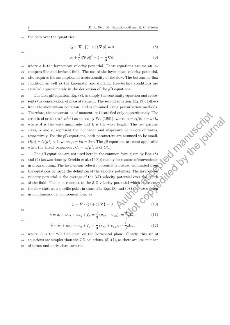
the bars over the quantities:166
ζt +∇ · (1 + ζ)∇φ = 0 , (8)
167
φt +1
2||∇φ||2 + ζ =
1
3∇φt , (9)
where φ is the layer-mean velocity potential. These equations assume an in-168
compressible and inviscid fluid. The use of the layer-mean velocity potential,169
also requires the assumption of irrotationality of the flow. The bottom no-flux170
condition as well as the kinematic and dynamic free-surface conditions are171
satisfied approximately in the derivation of the gB equations.172
The first gB equation, Eq. (8), is simply the continuity equation and repre-173
sents the conservation of mass statement. The second equation, Eq. (9), follows174
from the momentum equation, and is obtained using perturbation methods.175
Therefore, the conservation of momentum is satisfied only approximately. The176
error is of order (αǫ4, α2ǫ2) as shown by Wu (1981), where α = A/h, ǫ = h/L,177
where A is the wave amplitude and L is the wave length. The two param-178
eters, α and ǫ, represent the nonlinear and dispersive behaviors of waves,179
respectively. For the gB equations, both parameters are assumed to be small,180
O(α) = O(µ2) < 1, where µ = kh = 2πǫ. The gB equations are most applicable181
when the Ursell parameter, Ur = α/µ2, is of O(1).182
The gB equations are not used here in the common form given by Eqs. (8)183
and (9) (as was done by Ertekin et al. (1990)) mainly for reasons of convenience184
in programming. The layer-mean velocity potential is instead eliminated from185
the equations by using the definition of the velocity potential. The layer-mean186
velocity potential is the average of the 3-D velocity potential over the depth187
of the fluid. This is in contrast to the 3-D velocity potential which represents188
the flow state at a specific point in time. The Eqs. (8) and (9) then are written189
in nondimensional component form as190
ζt +∇ · (1 + ζ)V = 0 , (10)
191
u = ut + uux + vuy + ζx =1
3(uxx + uyy)t =
1
3∆ut , (11)
192
v = vt + uvx + vvy + ζy =1
3(vxx + vyy)t =
1
3∆vt , (12)
where ∆ is the 2-D Laplacian on the horizontal plane. Clearly, this set of193
equations are simpler than the GN equations, (5)-(7), as there are less number194
of terms and derivatives involved.195

Author
acce
pted m
anus
cript
Not co
pyed
ited b
y the
journ
al
Solitary Wave Diffraction by Vertical Cylinders 9
2.2 Initial and Boundary Conditions196
The initial conditions are chosen to correspond to a quiescent fluid, i.e., ζ(x, y, 0) =197
u(x, y, 0) = 0. Therefore, the velocities and surface elevations are initially set198
to zero at which time the incident waves are located outside the computational199
domain on the upwave side. The boundary conditions along the line of sym-200
metry, the surface of the cylinder, and the far wall, are the no-flux condition.201
This line of symmetry is along the wave propagation direction. The symmetry202
axis acts like a rigid surface, therefore, no flow is allowed through this surface.203
The normal velocity (v) therefore is equal to zero. The downwave boundary204
is an open boundary. The waves must be absorbed by this boundary without205
reflection. At the upwave boundary, the wavemaker solution, will be presented206
in subsequent sections for the solitary wave.207
The sea-floor no-flux condition, as well as the kinematic and dynamic free-208
surface conditions, are accounted for directly in the derivations of the gB209
(approximately) and GN (exactly) equations, and therefore, they are not given210
here. See Green and Naghdi (1976a) and Wu (1981) for details on how the211
boundary conditions are embedded into the GN and gB equations, respectively.212
Although we use a large computational domain for greater accuracy, it213
is necessary to use an absorption boundary on the downwave side. Previous214
works of Wu and Wu (1982) and Ertekin (1984) showed that the relatively215
simple Orlanski’s condition with constant phase speed c = ±√gh prevents216
significant reflections from the open-boundary. We use this open-boundary217
condition here which reads218
Ωt + cΩx = 0, (13)
where Ω may be ζ(x, t) or u(x, t) at the downwave boundary.219
It is noted that after the solitary wave has completely entered into the220
computational domain through the upwave boundary, the upwave boundary221
converts to the Orlanski condition, Eq. (13) (see e.g., Ertekin et al. (1986)) to222
absorb any reflected waves, similar to the downwave boundary.223
We note that with regards to the implementation of the open boundary224
condition, Eq. (13), the use of the incident wave speed on the downwave open225
boundary instead of the linear wave speed provides superior wave absorption.226
Since this boundary needs to absorb supercritical solitary waves, the introduc-227
tion of the incident wave speed in the Orlanski condition allows this radiation228
boundary to absorb the remainder of the incident wave after it had traversed229
Author
acce
pted m
anus
cript
Not co
pyed
ited b
y the
journ
al
10 D. R. Neill, M. Hayatdavoodi and R. C. Ertekin
the entire domain. The upwave boundary where the wavemaker is located need230
to absorb any reflections due to the diffraction of solitary waves, and therefore,231
the linear long-wavelength limit, c =√gh, is used for the wave speed in the232
Orlanski condition on the upwave boundary. We monitored the wave eleva-233
tions at various numerical wave gauges and observed that the open-boundary234
conditions work well with minimum amount of reflections.235
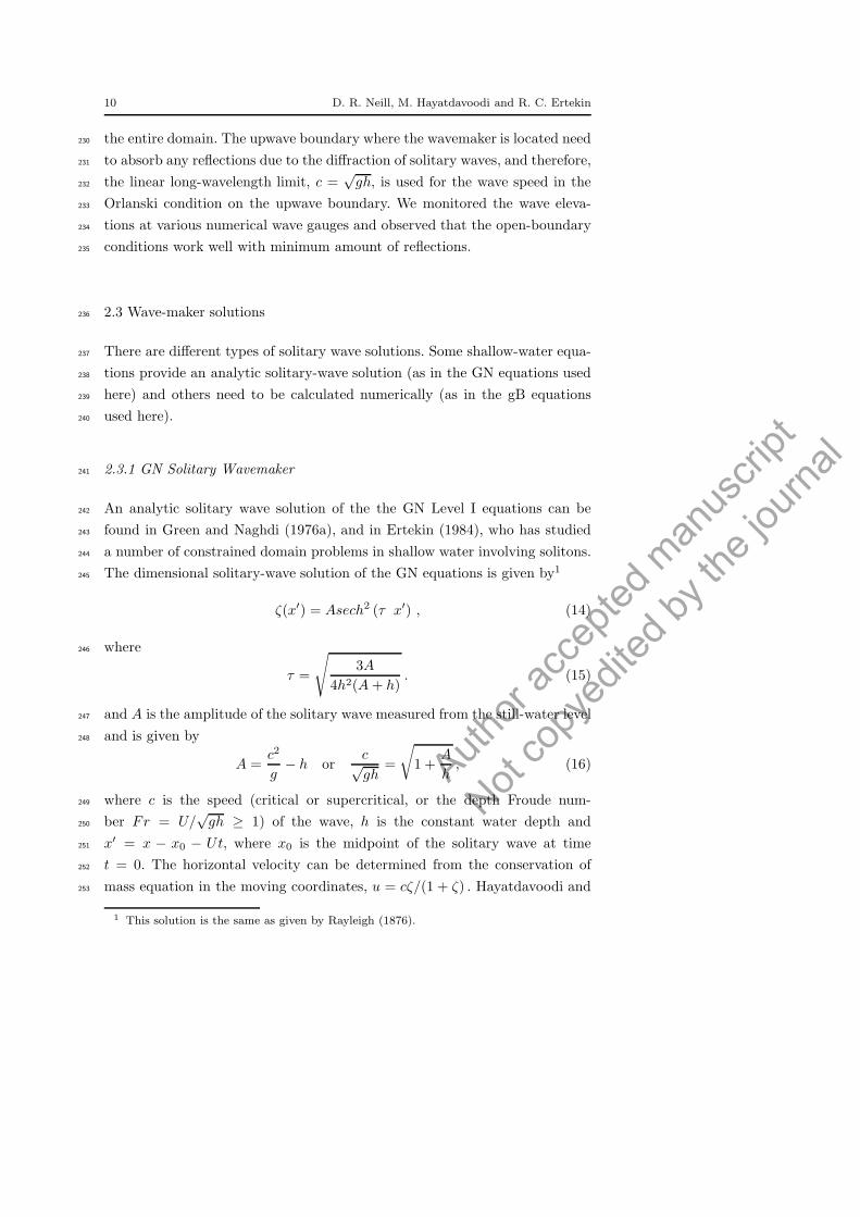
2.3 Wave-maker solutions236
There are different types of solitary wave solutions. Some shallow-water equa-237
tions provide an analytic solitary-wave solution (as in the GN equations used238
here) and others need to be calculated numerically (as in the gB equations239
used here).240
2.3.1 GN Solitary Wavemaker241
An analytic solitary wave solution of the the GN Level I equations can be242
found in Green and Naghdi (1976a), and in Ertekin (1984), who has studied243
a number of constrained domain problems in shallow water involving solitons.244
The dimensional solitary-wave solution of the GN equations is given by1245
ζ(x′) = Asech2 (τ x′) , (14)
where246
τ =
√
3A
4h2(A+ h). (15)
and A is the amplitude of the solitary wave measured from the still-water level247
and is given by248
A =c2
g− h or
c√gh
=
√
1 +A
h, (16)
where c is the speed (critical or supercritical, or the depth Froude num-249
ber Fr = U/√gh ≥ 1) of the wave, h is the constant water depth and250
x′ = x − x0 − Ut, where x0 is the midpoint of the solitary wave at time251
t = 0. The horizontal velocity can be determined from the conservation of252
mass equation in the moving coordinates, u = cζ/(1 + ζ) . Hayatdavoodi and253
1 This solution is the same as given by Rayleigh (1876).

Author
acce
pted m
anus
cript
Not co
pyed
ited b
y the
journ
al
Solitary Wave Diffraction by Vertical Cylinders 11
Ertekin (2015c) presented a closed-form of the GN solitary wave horizontal254
and vertical velocities as255
u(x′, 0) =√
g(A+ h)Asech2 (τx′)
h+Asech2 (τx′), (17)
w(x′, z, 0) =z + h
h+Asech2 (τx′)
(
2Asech2 (τx′) tanh (τx′))
(
√
g(A+ h)− u)
.
(18)
Since the solitary wave in theory has an infinite length, it is not necessary256
to modulate it as long as it is located well to the left of the upwave boundary257
at time t = 0. Discussion on the steady, solitary-wave solution of high-level258
GN equations can be found in Zhao et al. (2014b).259
2.3.2 gB Solitary Wavemaker260
The solitary wave solution of the gB equations uses the same numerically261
determined wave solution used by Qian (1994); Roddier and Ertekin (1999)262
(see also Teng and Wu (1992)). This solution is found by eliminating the time263
derivatives from the gB equations by converting them to the moving or wave264
coordinates. The gB equations then can be combined into a single differential265
equation:266
ζ2x =6
Fr2(1+ζ)4 ln(1+ζ)+
(
2 +6
Fr2
)
(1+ζ)4−(
3 +6
Fr2
)
(1+ζ3)+(1+ζ) ,
(19)
where Fr = c/√gh is the depth Froude number and c is the dimensional wave267
celerity as before. The wave profile then is determined iteratively from Eq.268
(19). The amplitude, A, of the soliton is input into Eq. (19) as the initial value269
of ζ at the wave crest. We then use the 4th-order Runge-Kutta method to270
determine the slope for other values of x′ to determine ζ(x′) at the next step271
x′
i+1 = x′
i +∆x′. This process is repeated until the wave profile is completed,272
also see e.g., Roddier (1994); Neill (1996) for more details.273
Author
acce
pted m
anus
cript
Not co
pyed
ited b
y the
journ
al
12 D. R. Neill, M. Hayatdavoodi and R. C. Ertekin
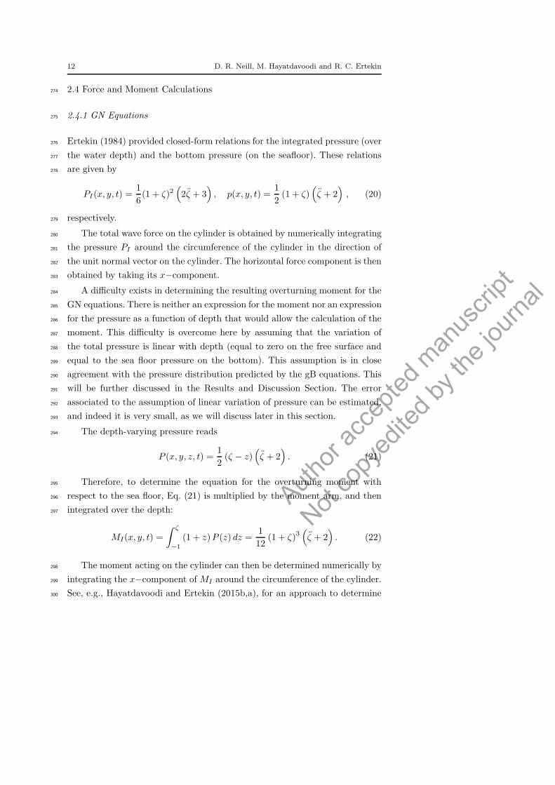
2.4 Force and Moment Calculations274
2.4.1 GN Equations275
Ertekin (1984) provided closed-form relations for the integrated pressure (over276
the water depth) and the bottom pressure (on the seafloor). These relations277
are given by278
PI(x, y, t) =1
6(1 + ζ)2
(
2ζ + 3)
, p(x, y, t) =1
2(1 + ζ)
(
ζ + 2)
, (20)
respectively.279
The total wave force on the cylinder is obtained by numerically integrating280
the pressure PI around the circumference of the cylinder in the direction of281
the unit normal vector on the cylinder. The horizontal force component is then282
obtained by taking its x−component.283
A difficulty exists in determining the resulting overturning moment for the284
GN equations. There is neither an expression for the moment nor an expression285
for the pressure as a function of depth that would allow the calculation of the286
moment. This difficulty is overcome here by assuming that the variation of287
the total pressure is linear with depth (equal to zero on the free surface and288
equal to the sea floor pressure on the bottom). This assumption is in close289
agreement with the pressure distribution predicted by the gB equations. This290
will be further discussed in the Results and Discussion Section. The error291
associated to the assumption of linear variation of pressure can be estimated,292
and indeed it is very small, as we will discuss later in this section.293
The depth-varying pressure reads294
P (x, y, z, t) =1
2(ζ − z)
(
ζ + 2)
. (21)
Therefore, to determine the equation for the overturning moment with295
respect to the sea floor, Eq. (21) is multiplied by the moment arm, and then296
integrated over the depth:297
MI(x, y, t) =
∫ ζ
−1
(1 + z)P (z) dz =1
12(1 + ζ)3
(
ζ + 2)
. (22)
The moment acting on the cylinder can then be determined numerically by298
integrating the x−component of MI around the circumference of the cylinder.299
See, e.g., Hayatdavoodi and Ertekin (2015b,a), for an approach to determine300

Author
acce
pted m
anus
cript
Not co
pyed
ited b
y the
journ
al
Solitary Wave Diffraction by Vertical Cylinders 13
the wave-induced loads on horizontal objects by use of the Level I GN equa-301
tions.302
To determine the error of using Eq. (21) in approximating the pressure303
distribution in the z direction, we integrate P (x, y, z, t) of Eq. (21) over the304
water depth:305
PIL(x, y, t) =
∫ ζ
−1
P (x, y, z, t) dz =1
4(1 + ζ)
2(
ζ + 2)
. (23)
The percent error, ǫ, made by the assumption of linearly-varying total pres-306
sure along the water column is then determined by comparing the integrated307
(linearly-varying) pressure, PIL, with the integrated pressure of the GN equa-308
tions given by Eq. (20):309
ǫ =
∣
∣
∣
∣
PI − PIL
PI
∣
∣
∣
∣
× 100 =
∣
∣
∣
∣
∣
ζ
4ζ + 6
∣
∣
∣
∣
∣
× 100. (24)
Although Eq. (24) determines the error produced by the integrated pressure,310
it also is a reasonable estimate of the error produced by the moment equation311
(22). This error is determined for every node along the cylinder boundary and312
then an average is calculated. This average is then used as an approximate313
error value in the moment calculations as discussed later in Section 5.3.314
2.4.2 gB Equations315
Unlike the GN equations, the pressure as a function of depth is provided by the316
gB equations in terms of the layer-mean potential, see Wu (1981). However,317
we write the gB pressure equation in dimensionless velocity form:318
P (z) = ζ − z +
(
z +1
2z2)
∇ · V t. (25)
To facilitate the determination of the force, we integrate Eq. (25) over the319
water column and obtain320
PI =1
2(1 + ζ)
2+
1
6(1 + ζ)
(
ζ2 + 2(ζ − 1))
∇ · V . (26)
Multiplying Eq. (25) by the moment arm and integrating over the depth321
gives the expression for the overturning moment (about the y axis) with respect322

Author
acce
pted m
anus
cript
Not co
pyed
ited b
y the
journ
al
14 D. R. Neill, M. Hayatdavoodi and R. C. Ertekin
to the seafloor:323
MI =1
6(1 + ζ)
3+
1
8(1 + ζ)
2(
(1 + ζ)2 − 2
)
∇ · V t . (27)
Finally, the integrated pressure and moment, PI and MI , are numerically324
integrated around the circumference of the cylinder in the direction of the unit325
normals on the cylinder to determine the horizontal force in the x direction326
and the overturning moment about the y axis, respectively.327
3 Grid Generation328
To facilitate the use of finite-difference methods to solve shallow water wave329
equations in the presence of irregular boundaries, numerical grid generation is330
used in this study. The use of numerical grid generation allows the inclusion331
of irregular boundaries conveniently by mapping the physical domain into a332
rectangular computational domain. The grid chosen for the computational333
domain is both regular and rectangular. This is not a requirement for the use334
of the grid-generation transformation system. It does, however, significantly335
reduce the complexity of the computations. The present study uses an elliptical336
generation technique in a connected 2-D region. Since the problem contains a337
symmetry axis, only one half of the region needs to be analyzed. Therefore, the338
grid system does not need to have re-entrant boundaries in either the physical339
or transformed plan.340
The use of elliptical grid generation technique has been described exten-341
sively by, for example, Thompson et al. (1977). In this technique, a one-to-one342
mapping is developed between the physical plane and the computational plane343
by use of the Laplace equation. A uniform computational grid system with unit344
interval spacings is used in the solution of all the governing equations. This345
greatly simplifies the use of finite-difference methods. The minimization of the346
Euler integral ensures a one-to-one mapping. Details on the transformation347
of the governing equations as used in this work can be found in Qian (1988);348
Ertekin et al. (1990).349
4 Numerical Method350
We use the finite-difference method to solve the partial differential equations351
that govern the fluid motion. The difference equations are found through the352

Author
acce
pted m
anus
cript
Not co
pyed
ited b
y the
journ
al
Solitary Wave Diffraction by Vertical Cylinders 15
use of the second-order central difference formulas in space. To use the dif-353
ference equations along the boundaries, a fictitious point method is used. For354
example, along any boundary x = x1, the equation for the first derivative355
would be356
f ′(x1) =f(x0)− f(x2)
2∆x+O(∆x2). (28)
However, since x0 is outside of the boundary, f(x0) is undefined. A fictitious357
value for f(x0) is found through a parabolic approximation: f0 = 3f1−3f2+f3.358
By combining this equation with Eq.(28), a new equation is produced for the359
first derivative along the boundary:360
f ′(x1) =−3f(x1) + 4f(x2)− f(x3)
2∆x+O(∆x2). (29)
This method can be used to produce equations for all the derivatives along the361
boundaries, see Roddier (1994); Roddier and Ertekin (1999) for more details.362
We use the time marching technique known as the modified Euler method,363
see e.g., Burden and Faires (1985). This two-step method has second-order364
accuracy. This method was also used successfully by Ertekin (1984); Ertekin365
et al. (1986); Roddier and Ertekin (1999); Hayatdavoodi and Ertekin (2015c),366
among others, in the solution of the GN and gB equations in 2-D.367
The Successive Over-Relaxation (SOR) iterative method is used to solve368
the transformed forms of three sets of equations: GN Eqs. (5), (6), (7); and gB369
Eqs. (10), (11), (12). Two modifications are made to this method to improve370
the computational efficiency. Normally, the solution for u and v at the last371
time step is used as the initial guess for the next time step. In this analysis,372
however, the initial guess is extrapolated from the last two time steps using373
uk+1(i, j)−2uk(i, j)−uk−1(i, j) and vk+1(i, j)−2vk(i, j)−vk−1(i, j), where k is374
the time counter. Shown by Roddier and Ertekin (1999), this method reduces375
the number of SOR iterations by more than 40%. The second modification is376
to alternate the starting point and order of the iterations. Instead of always377
starting at i = 1, j = 1, the starting point is alternated between the four378
corners of the computational domain, A(i = 1, j = 1), D(i = 1, j = n), E(i =379
m, j = 1) and F (i = m, j = n). This technique also reduced the number of380
iterations.381
The analysis carried out here requires filtering to remove numerical noise382
and ensure stability as pointed out by Ertekin et al. (1986). Much of this383
noise is the result of the central-difference scheme. When insufficient filtering384
is applied, the results become unstable. The third-order filtering by itself does385

Author
acce
pted m
anus
cript
Not co
pyed
ited b
y the
journ
al
16 D. R. Neill, M. Hayatdavoodi and R. C. Ertekin
not provide sufficient stability. Our studies show that a combination of the386
five- (2nd order) and seven-point (3rd order) linear filtering schemes used here387
was developed by Shapiro (1975) and proved adequate to ensure stability.388
This includes the use of a third-order filtering in the direction normal to the389
prevailing wave crests, the ξ direction, and a second-order filtering parallel390
to the wave crests, the η direction. This does not modify the shape of the391
incoming waves. The filtering formulas that we use are given by392
fj =1
16(−fj−2 + 4fj−1 + 10fj + 4fj+1 − fj−2) ,
fi =1
64(−fi−3 − 6fi−2 + 15fi−1 + 44fi + 15fi+1 − 6fi+2 + fi+3) ,
(30)
where f is a generic variable that can represent ζ, u or v.393
5 Error Monitoring394
5.1 Conservation of Mass395
To monitor the accuracy of the numerical solutions, the change in the mass396
due to numerical errors is determined following the approach used by Qian397
(1994); Roddier (1994). Conservation of mass is satisfied exactly for both the398
Green-Naghdi and the Boussinesq equations. Except for mass passing through399
the upstream or downstream boundaries, any change in mass is due to nu-400
merical errors. The Green-Naghdi equations exactly satisfy the conservation401
of momentum in the depth averaged sense, while the Boussinesq equations402
satisfy the momentum conservation approximately. Therefore, to monitor the403
numerical errors, the change in mass is chosen (preferred) here over the change404
in momentum or mechanical energy.405
The total excess mass inside the physical domain (M), at a specific time,406
is determined by numerically integrating over the water column and over the407
surface area of the physical domain:408
M =
∫
A
(1 + ζ) dA. (31)
The mass flow through the open boundaries is determined by integrating409
over these boundaries:410

Author
acce
pted m
anus
cript
Not co
pyed
ited b
y the
journ
al
Solitary Wave Diffraction by Vertical Cylinders 17
dmUS =
∫
US
(1 + ζ) (v.n) ds , (32)
dmDS =
∫
DS
(1 + ζ) (v.n) ds , (33)
where, dmUS is the mass flow through the upstream boundary, and dmDS is411
the mass flow through the downstream boundary. These boundaries are normal412
to the y-axis, therefore, the dot product of the velocity vector (v) and the unit413
normal (n) is simply the horizontal velocity in the x-direction (u). Therefore,414
Eqs. (32) and (33) are simplified to415
dmUS =
∫
US
(1 + ζ) uds , (34)
dmDS =
∫
DS
(1 + ζ) uds . (35)
These equations must also be integrated over time to determine the total416
loss or gain of mass across these boundaries.417
dmUS =
∫
t
∫
US
(1 + ζ) (v.n) dsdt′ , (36)
dmDS =
∫
t
∫
DS
(1 + ζ) (v.n) dsdt′ , (37)
where both the temporal and spacial integrations are performed numerically418
using Simpsons rule.419
The total change in mass (dMe) which is a result of numerical errors is420
found through the following relationship:421
dMe = M −M0 − dMUS + dMDS , (38)
where M0 is the initial total mass which is equal to ρVD, where VD is the422
volume of the quiescent body of fluid. The percent change in mass due to423
numerical errors can then be calculated through424
ME =dMe
M0
∗ 100(%) . (39)
The percent change in mass, as a function of time, is determined for each425
case. Some sample values for ME for both the Green-Naghdi and the Boussi-426
Author
acce
pted m
anus
cript
Not co
pyed
ited b
y the
journ
al
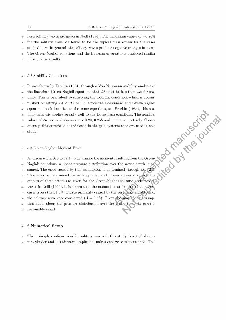
18 D. R. Neill, M. Hayatdavoodi and R. C. Ertekin
nesq solitary waves are given in Neill (1996). The maximum values of −0.20%427
for the solitary wave are found to be the typical mass excess for the cases428
studied here. In general, the solitary waves produce negative changes in mass.429
The Green-Naghdi equations and the Boussinesq equations produced similar430
mass change results.431
5.2 Stability Conditions432
It was shown by Ertekin (1984) through a Von Neumann stability analysis of433
the linearized Green-Naghdi equations that ∆t must be less than ∆x for sta-434
bility. This is equivalent to satisfying the Courant condition, which is accom-435
plished by setting ∆t < ∆x or ∆y. Since the Boussinesq and Green-Naghdi436
equations both linearize to the same equations, see Ertekin (1984), this sta-437
bility analysis applies equally well to the Boussinesq equations. The nominal438
values of ∆t, ∆x and ∆y used are 0.20, 0.25h and 0.33h, respectively. Conse-439
quently, this criteria is not violated in the grid systems that are used in this440
study.441
5.3 Green-Naghdi Moment Error442
As discussed in Section 2.4, to determine the moment resulting from the Green-443
Naghdi equations, a linear pressure distribution over the water depth is as-444
sumed. The error caused by this assumption is determined through Eq. (24).445
This error is determined for each cylinder and in every case analyzed. Ex-446
amples of these errors are given for the Green-Naghdi solitary, and cnoidal,447
waves in Neill (1996). It is shown that the moment error for the solitary wave448
cases is less than 1.8%. This is primarily caused by the very large amplitude of449
the solitary wave case considered (A = 0.5h). Given the simplifying assump-450
tion made about the pressure distribution over the z direction, the error is451
reasonably small.452
6 Numerical Setup453
The principle configuration for solitary waves in this study is a 4.0h diame-454
ter cylinder and a 0.5h wave amplitude, unless otherwise is mentioned. This455

Author
acce
pted m
anus
cript
Not co
pyed
ited b
y the
journ
al
Solitary Wave Diffraction by Vertical Cylinders 19
configuration is used in many solitary wave cases and is chosen primarily to fa-456
cilitate the comparison with other studies. Moreover, the 0.5h wave amplitude457
is at the practical limit of use for the gB equations. According to Mei (1989),458
these equations are applicable for O(A) < 1. This limit is a result of the as-459
sumptions that led to the derivation of these equations. Although the GN460
equations do not have an explicit limit, they must, nevertheless, have similar461
implicit limitations. Any such limitations of the GN equations must be judged462
by comparison with experiments.463
The 4.0h cylinder diameter is also a convenient and reasonable size. This464
size is large enough to produce significant diffraction, and is easily modeled465
numerically. Smaller cylinders would require finer grids for the same accuracy466
and viscous forces may become important. A larger diameter cylinder would467
require a larger domain. Clearly, the latter two factors would increase the468
computational time significantly.469
The domain used includes a 20h distance from the upwave boundary to470
the first cylinder surface, a 20h distance from the last cylinder surface to the471
downwave boundary and a 20h distance from the far wall to the symmetry472
axis. It will be shown later that this domain is large enough to avoid problems473
of wave interactions at the boundaries that affect the resulting forces and474
moments on the cylinders.475
The nominal (dimensionless) grid sizes used in this domain are ∆x = 0.25476
and ∆y = 0.33. These sizes are small enough to adequately model the surface477
displacements and large enough to not require excessive CPU (central process-478
ing unit) time. To insure stability, the time step must be smaller than the grid479
size as discussed before. Therefore, the time step is chosen as ∆t = 0.2.480
7 Results and Discussion481
Results of the GN and the gB equations for solitary wave interaction with ver-482
tical cylinders are presented and discussed in this section. We will first start483
by solitary wave interaction with a single cylinder and compare the results of484
the theoretical models with the existing laboratory measurements and other485
theories. This is then followed by results and discussion on solitary wave in-486
teraction with two and three in-line vertical cylinders. We note that in this487
study, and for the two and three cylinder configurations, all cylinders have the488
same diameter.489
Author
acce
pted m
anus
cript
Not co
pyed
ited b
y the
journ
al
20 D. R. Neill, M. Hayatdavoodi and R. C. Ertekin
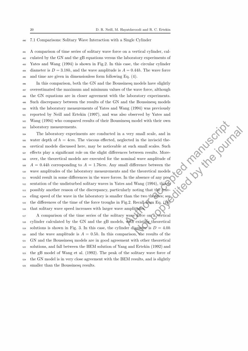
7.1 Comparisons: Solitary Wave Interaction with a Single Cylinder490
A comparison of time series of solitary wave force on a vertical cylinder, cal-491
culated by the GN and the gB equations versus the laboratory experiments of492
Yates and Wang (1994) is shown in Fig.2. In this case, the circular cylinder493
diameter is D = 3.18h, and the wave amplitude is A = 0.44h. The wave force494
and time are given in dimensionless form following Eq. (4).495
In this comparison, both the GN and the Boussinesq models have slightly496
overestimated the maximum and minimum values of the wave force, although497
the GN equations are in closer agreement with the laboratory experiments.498
Such discrepancy between the results of the GN and the Boussinesq models499
with the laboratory measurements of Yates and Wang (1994) was previously500
reported by Neill and Ertekin (1997), and was also observed by Yates and501
Wang (1994) who compared results of their Boussinesq model with their own502
laboratory measurements.503
The laboratory experiments are conducted in a very small scale, and in504
water depth of h = 4cm. The viscous effected, neglected in the inviscid the-505
oretical models discussed here, may be noticeable at such small scales. Such506
effects play a significant role on the slight differences between results. More-507
over, the theoretical models are executed for the nominal wave amplitude of508
A = 0.44h corresponding to A = 1.76cm. Any small difference between the509
wave amplitudes of the laboratory measurements and the theoretical models510
would result in some differences in the wave forces. In the absence of any pre-511
sentation of the undisturbed solitary waves in Yates and Wang (1994), this is512
possibly another reason of the discrepancy, particularly noting that the trav-513
eling speed of the wave in the laboratory is smaller than the two theories; see514
the differences of the time of the force troughs in Fig.2. Recall from Eq. (16)515
that solitary wave speed increases with larger wave amplitudes.516
A comparison of the time series of the solitary wave force on a vertical517
cylinder calculated by the GN and the gB models, with existing theoretical518
solutions is shown in Fig. 3. In this case, the cylinder diameter is D = 4.0h519
and the wave amplitude is A = 0.5h. In this comparison, the results of the520
GN and the Boussinesq models are in good agreement with other theoretical521
solutions, and fall between the BEM solution of Yang and Ertekin (1992) and522
the gB model of Wang et al. (1992). The peak of the solitary wave force of523
the GN model is in very close agreement with the BEM results, and is slightly524
smaller than the Boussinesq results.525

Author
acce
pted m
anus
cript
Not co
pyed
ited b
y the
journ
al
Solitary Wave Diffraction by Vertical Cylinders 21
t
0 5 10 15 20 25 30
F
-2
-1.5
-1
-0.5
0
0.5
1
1.5
2Experiments (Yates and Wang 1994)GNBoussinesq
Fig. 2 Comparison of time series of solitary wave force on a single, vertical cylinder calcu-lated by the GN and gB equations versus the laboratory experiments of Yates and Wang(1994). A = 0.44h and D = 3.18h.
The analytical solution of Isaacson (1978) of wave force on the vertical526
cylinder has underestimated the force amplitude when compared to other so-527
lutions. In contrast, the Boussinesq model results of Wang et al. (1992) over528
estimates the force amplitude when compared to other results. Such overesti-529
mation appears to be due to the error associated to the mesh and the numerical530
solution of the equations. As discussed by Neill (1996), the wave run-up on the531
cylinder, and consequently the peak of the solitary wave forces, would increase532
if grid repulsion is not used, as in the Boussinseq model of Wang et al. (1992).533
The use of the grid repulsion improves the grid line orthogonality along the534
curved boundaries. The larger wave run-up in the Wang et al. (1992) model,535
also causes a larger wave reflection, resulting in smaller force trough when536
compared with the Boussinesq model discussed here, see Fig. 3.537
Further results and discussion of the GN and the gB models on solitary538
wave interaction with a single cylinder can be found in Neill and Ertekin539
(1997).540
7.2 Solitary Wave Interaction with Two Cylinders541
The two cylinder solitary wave case also uses the same 4.0h diameter cylinder542
and 0.5h wave amplitude used before. This allows direct comparison with543

Author
acce
pted m
anus
cript
Not co
pyed
ited b
y the
journ
al
22 D. R. Neill, M. Hayatdavoodi and R. C. Ertekin
t
0 5 10 15 20 25 30 35 40
F
-2
-1
0
1
2 Closed form (Isaacson 1978)BEM (Yang and Ertekin 1992)Boussinesq (Wang et al. 1992)GNBoussinesq (present)
Fig. 3 Comparison of time series of solitary wave force on a single, vertical cylinder cal-culated by the GN and gB equations and existing theoretical solutions. A = 0.5h andD = 4.0h.
Wang and Jiang (1994) who used the gB equations to study this configuration.544
Various spacings are used between the cylinders. In this section, the spacings545
used are 0.50D, 0.75D, 1.00D, 2.00D and 3.00D, where D, the diameter of546
the cylinder, is the same for both cylinders. The spacing between the two547
cylinders is measured as the closest distance between the cylinders. This is the548
same definition for spacing used by Wang and Jiang (1994). These spacings549
correspond to distances from the wave maker to the second cylinder center of550
28h, 29h, 30h, 34h and 38h, respectively. Wang and Jiang (1994) also used the551
spacings of 0.0D and 0.25D. For the S = 0.0D spacing, the cylinder surfaces552
are in direct contact with each other.553
Sample snapshots of the solitary wave surface elevations, calculated by554
the gB and the GN equations, are shown in Figs. 4 and 5, respectively. The555
resultant forces and moments in our study are shown in Figs. 6 and 7 for the556
gB equations and in Figs. 8 and 9. for the GN equations. Note that, the single557
cylinder results are also shown in these figures.558
In general, the GN equations predict less shielding than the gB equations.559
Shielding is the reduction in force and moment on the downwave cylinder560
caused by the interaction of the waves on the upwave cylinder. The gB equa-561
tions predict a greater run-up on the first cylinder. This greater run-up causes562
more significant wave reflection and therefore there is a greater reduction in563

Author
acce
pted m
anus
cript
Not co
pyed
ited b
y the
journ
al
Solitary Wave Diffraction by Vertical Cylinders 23
Fig. 4 3-D snapshots of solitary wave surface elevation around two cylinders, calculated bythe gB equations, S = 1.0D,D = 4.0h and H = 0.5h.
Fig. 5 3-D snapshots of solitary wave surface elevation around two cylinders, calculated bythe GN equations, S = 1.0D,D = 4.0h and H = 0.5h.
the wave amplitude downwave of the cylinder, and hence a greater reduction564
in the resulting force on the downwave cylinder.565
The shielding described by Wang and Jiang (1994) is similar to the shield-566
ing found in this study. After the wave impacts the first cylinder, a 3-dimensional567
back-scattered wave emerges in front of the first cylinder. The primary wave568
deforms behind the first cylinder with a reduced wave amplitude. Therefore,569
the wave runup, force and moment are less for the second cylinder than the570

Author
acce
pted m
anus
cript
Not co
pyed
ited b
y the
journ
al
24 D. R. Neill, M. Hayatdavoodi and R. C. Ertekin
Fig. 6 Solitary wave forces on the (a)first and (b)second cylinder, for the two cylinder case,calculated by the gB equations, H = 0.5h,D = 4.0h.
Fig. 7 Solitary wave moment on the (a)first and (b)second cylinder, for the two cylindercase, calculated by the gB equations, H = 0.5h,D = 4.0h.
first. The gB solution in this study consistently produces similar result to that571
of Wang and Jiang (1994), see Figs. 6 and 7. The small differences may be572
due to the lack of boundary orthogonality control in Wang and Jiang (1994)573
which causes the peak force value to be over-predicted. In both this study and574
Wang and Jiang (1994), the maximum force on the first cylinder is unaffected575
by the presence of the second cylinder. The maximum force on the second576
cylinder (Fmax = 1.60), calculated by the gB equations in this study, is 21.6%577
Author
acce
pted m
anus
cript
Not co
pyed
ited b
y the
journ
al
Solitary Wave Diffraction by Vertical Cylinders 25
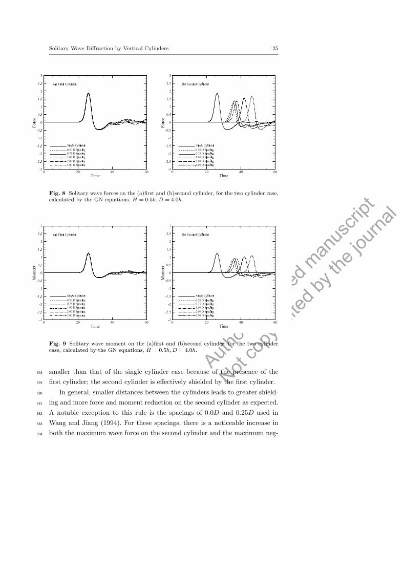
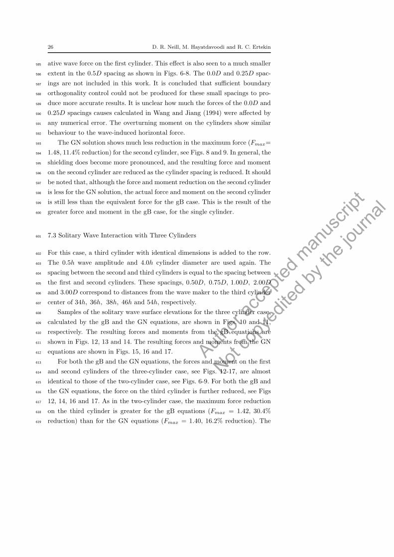
Fig. 8 Solitary wave forces on the (a)first and (b)second cylinder, for the two cylinder case,calculated by the GN equations, H = 0.5h,D = 4.0h.
Fig. 9 Solitary wave moment on the (a)first and (b)second cylinder, for the two cylindercase, calculated by the GN equations, H = 0.5h,D = 4.0h.
smaller than that of the single cylinder case because of the presence of the578
first cylinder; the second cylinder is effectively shielded by the first cylinder.579
In general, smaller distances between the cylinders leads to greater shield-580
ing and more force and moment reduction on the second cylinder as expected.581
A notable exception to this rule is the spacings of 0.0D and 0.25D used in582
Wang and Jiang (1994). For these spacings, there is a noticeable increase in583
both the maximum wave force on the second cylinder and the maximum neg-584
Author
acce
pted m
anus
cript
Not co
pyed
ited b
y the
journ
al
26 D. R. Neill, M. Hayatdavoodi and R. C. Ertekin
ative wave force on the first cylinder. This effect is also seen to a much smaller585
extent in the 0.5D spacing as shown in Figs. 6-8. The 0.0D and 0.25D spac-586
ings are not included in this work. It is concluded that sufficient boundary587
orthogonality control could not be produced for these small spacings to pro-588
duce more accurate results. It is unclear how much the forces of the 0.0D and589
0.25D spacings causes calculated in Wang and Jiang (1994) were affected by590
any numerical error. The overturning moment on the cylinders show similar591
behaviour to the wave-induced horizontal force.592
The GN solution shows much less reduction in the maximum force (Fmax=593
1.48, 11.4% reduction) for the second cylinder, see Figs. 8 and 9. In general, the594
shielding does become more pronounced, and the resulting force and moment595
on the second cylinder are reduced as the cylinder spacing is reduced. It should596
be noted that, although the force and moment reduction on the second cylinder597
is less for the GN solution, the actual force and moment on the second cylinder598
is still less than the equivalent force for the gB case. This is the result of the599
greater force and moment in the gB case, for the single cylinder.600
7.3 Solitary Wave Interaction with Three Cylinders601
For this case, a third cylinder with identical dimensions is added to the row.602
The 0.5h wave amplitude and 4.0h cylinder diameter are used again. The603
spacing between the second and third cylinders is equal to the spacing between604
the first and second cylinders. These spacings, 0.50D, 0.75D, 1.00D, 2.00D605
and 3.00D correspond to distances from the wave maker to the third cylinder606
center of 34h, 36h, 38h, 46h and 54h, respectively.607
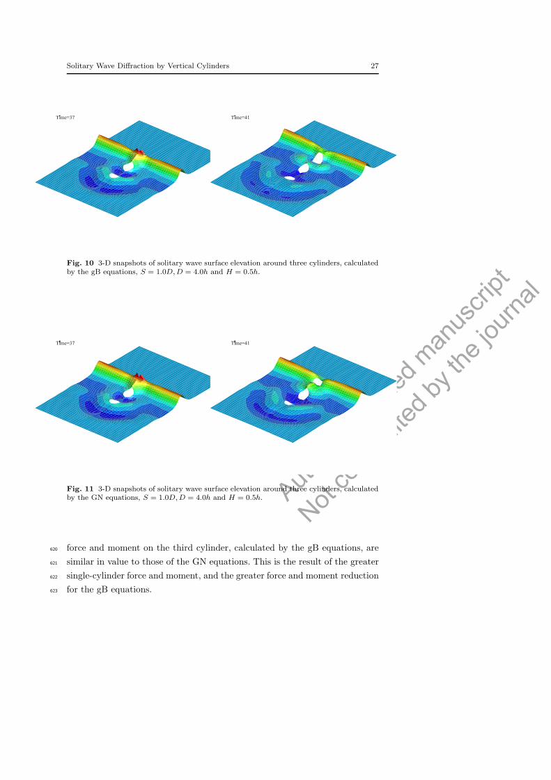
Samples of the solitary wave surface elevations for the three cylinder case,608
calculated by the gB and the GN equations, are shown in Figs. 10 and 11,609
respectively. The resulting forces and moments from the gB equations are610
shown in Figs. 12, 13 and 14. The resulting forces and moments from the GN611
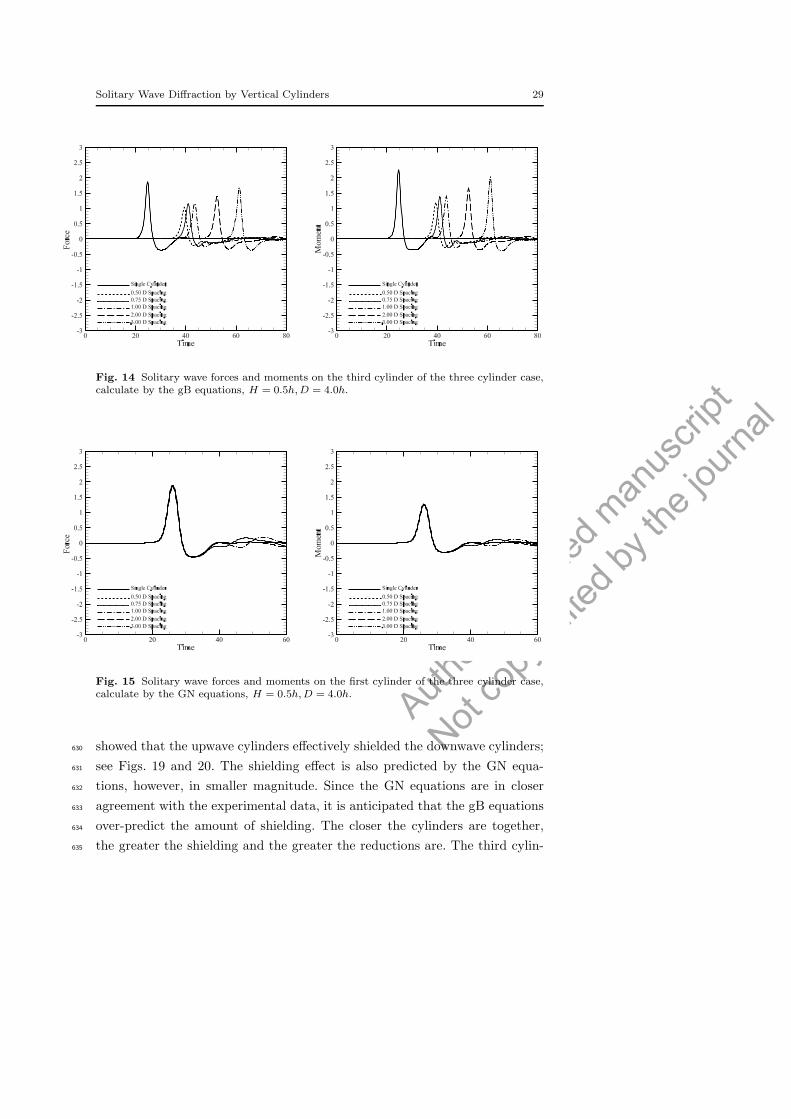
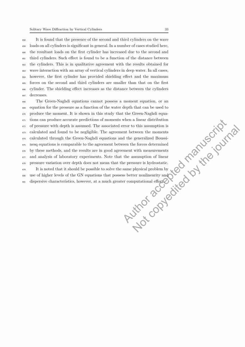
equations are shown in Figs. 15, 16 and 17.612
For both the gB and the GN equations, the forces and moment on the first613
and second cylinders of the three-cylinder case, see Figs. 12-17, are almost614
identical to those of the two-cylinder case, see Figs. 6-9. For both the gB and615
the GN equations, the force on the third cylinder is further reduced, see Figs616
12, 14, 16 and 17. As in the two-cylinder case, the maximum force reduction617
on the third cylinder is greater for the gB equations (Fmax = 1.42, 30.4%618
reduction) than for the GN equations (Fmax = 1.40, 16.2% reduction). The619
Author
acce
pted m
anus
cript
Not co
pyed
ited b
y the
journ
al
Solitary Wave Diffraction by Vertical Cylinders 27
Fig. 10 3-D snapshots of solitary wave surface elevation around three cylinders, calculatedby the gB equations, S = 1.0D,D = 4.0h and H = 0.5h.
Fig. 11 3-D snapshots of solitary wave surface elevation around three cylinders, calculatedby the GN equations, S = 1.0D,D = 4.0h and H = 0.5h.
force and moment on the third cylinder, calculated by the gB equations, are620
similar in value to those of the GN equations. This is the result of the greater621
single-cylinder force and moment, and the greater force and moment reduction622
for the gB equations.623

Author
acce
pted m
anus
cript
Not co
pyed
ited b
y the
journ
al
28 D. R. Neill, M. Hayatdavoodi and R. C. Ertekin
Fig. 12 Solitary wave forces and moments on the first cylinder of the three cylinder case,calculate by the gB equations, H = 0.5h,D = 4.0h.
Fig. 13 Solitary wave forces and moments on the second cylinder of the three cylinder case,calculate by the gB equations, H = 0.5h,D = 4.0h.
7.4 Further Discussion on Solitary Wave Forces624
The maximum forces resulting from solitary waves for the one, two and the625
three cylinder cases are shown in Figs. 18, 19 and 20. The single cylinder case626
corresponds to (S/D) → ∞. The maximum force is the maximum absolute627
value of the horizontal force acting on the individual cylinders. The gB equa-628
tions, both in this study and in the earlier study of Wang and Jiang (1994),629
Author
acce
pted m
anus
cript
Not co
pyed
ited b
y the
journ
al
Solitary Wave Diffraction by Vertical Cylinders 29
Fig. 14 Solitary wave forces and moments on the third cylinder of the three cylinder case,calculate by the gB equations, H = 0.5h,D = 4.0h.
Fig. 15 Solitary wave forces and moments on the first cylinder of the three cylinder case,calculate by the GN equations, H = 0.5h,D = 4.0h.
showed that the upwave cylinders effectively shielded the downwave cylinders;630
see Figs. 19 and 20. The shielding effect is also predicted by the GN equa-631
tions, however, in smaller magnitude. Since the GN equations are in closer632
agreement with the experimental data, it is anticipated that the gB equations633
over-predict the amount of shielding. The closer the cylinders are together,634
the greater the shielding and the greater the reductions are. The third cylin-635

Author
acce
pted m
anus
cript
Not co
pyed
ited b
y the
journ
al
30 D. R. Neill, M. Hayatdavoodi and R. C. Ertekin
Fig. 16 Solitary wave forces and moments on the second cylinder of the three cylinder case,calculate by the GN equations, H = 0.5h,D = 4.0h.
Fig. 17 Solitary wave forces and moments on the third cylinder of the three cylinder case,calculate by the GN equations, H = 0.5h,D = 4.0h.
der receives more shielding than the second cylinder. The downwave cylinders636
have negligible effect on the upwave cylinders.637
8 Concluding Remarks638
The problem of interaction of solitary waves with multiple in-line fixed, verti-639
cal, circular cylinders in shallow water is studied by use of the Green-Naghdi640

Author
acce
pted m
anus
cript
Not co
pyed
ited b
y the
journ
al
Solitary Wave Diffraction by Vertical Cylinders 31
0 0.5 1 1.5 2 2.5 3 3.51
1.5
2
2.5
Cylinder Spacing (S/D)
Max
imum
For
ce
Boussinesq, 1st of 2 cyl.GN, 1st of 2 cyl.Boussinesq, 1st of 3 cyl.GN, 1st of 3 cyl.Boussinesq, single cyl.GN, single cyl.
Fig. 18 Solitary wave maximum forces on the first cylinder, for one, two and three cylinderscases, versus cylinder spacing, H = 0.5h and D = 4.0h
0 0.5 1 1.5 2 2.5 3 3.51
1.5
2
2.5
Cylinder Spacing (S/D)
Max
imum
For
ce
Boussinesq, 2nd of 2 cyl.GN, 2nd of 2 cyl.Boussinesq, 2nd of 3 cyl.GN, 2nd of 3 cyl.Boussinesq, single cyl.GN, single cyl.
Fig. 19 Solitary wave maximum forces on the second cylinder, for one, two and threecylinders cases, versus cylinder spacing, H = 0.5h and D = 4.0h

Author
acce
pted m
anus
cript
Not co
pyed
ited b
y the
journ
al
32 D. R. Neill, M. Hayatdavoodi and R. C. Ertekin
0 0.5 1 1.5 2 2.5 3 3.51
1.5
2
2.5
Cylinder Spacing (S/D)
Max
imum
For
ce
Boussinesq, 3rd of 3 cyl.GN, 3rd of 3 cyl.Boussinesq, single cyl.GN, single cyl.
Fig. 20 Solitary wave maximum forces on the third cylinder, for one, two and three cylinderscases, versus cylinder spacing, H = 0.5h and D = 4.0h
equations and the Boussinesq equations. The solution is formulated using a641
boundary-fitted curvilinear coordinate system that allows utilizing a finite-642
difference method in solving the problem. The wave-induced horizontal force643
and the overturning moment are obtained by integrating the pressure around644
the vertical cylinders. In the model developed based on the Green-Naghdi645
equations, the total pressure distribution around the vertical cylinders is ob-646
tained assuming a linear distribution of pressure over the water column. Ac-647
curacy and error associated with the numerical calculations can be assessed648
by monitoring the mass and moment throughout the computations.649
Overall, close agreement is observed between the results of the Green-650
Naghdi equations and the Boussinesq equations with laboratory measurements651
and existing theoretical solutions. The performance of the Green-Naghdi equa-652
tions is found to be generally better than the Boussinesq equations. They pro-653
duce values for the forces and the moments that are in slightly closer agreement654
with both the experimental data and other predictions. The results of the GN655
equations and the Boussinesq equations are in closer agreement for smaller656
cylinder spacings.657
Author
acce
pted m
anus
cript
Not co
pyed
ited b
y the
journ
al
Solitary Wave Diffraction by Vertical Cylinders 33
It is found that the presence of the second and third cylinders on the wave658
loads on all cylinders is significant in general. In a number of cases studied here,659
the resultant loads on the first cylinder has increased due to the second and660
third cylinders. Such effect is found to be a function of the distance between661
the cylinders. This is in qualitative agreement with the results obtained for662
wave interaction with an array of vertical cylinders in deep water. In all cases,663
however, the first cylinder has provided shielding effect and the maximum664
forces on the second and third cylinders are smaller than that on the first665
cylinder. The shielding effect increases as the distance between the cylinders666
decreases.667
The Green-Naghdi equations cannot possess a moment equation, or an668
equation for the pressure as a function of the water depth that can be used to669
produce the moment. It is shown in this study that the Green-Naghdi equa-670
tions can produce accurate predictions of moments when a linear distribution671
of pressure with depth is assumed. The associated error to this assumption is672
calculated and found to be negligible. The agreement between the moments673
calculated through the Green-Naghdi equations and the generalized Boussi-674
nesq equations is comparable to the agreement between the forces determined675
by these methods, and the results are in good agreement with measurements676
and analysis of laboratory experiments. Note that the assumption of linear677
pressure variation over depth does not mean that the pressure is hydrostatic.678
It is noted that it should be possible to solve the same physical problem by679
use of higher levels of the GN equations that possess better nonlinearity and680
dispersive characteristics, however, at a much greater computational effort.681

Author
acce
pted m
anus
cript
Not co
pyed
ited b
y the
journ
al
34 D. R. Neill, M. Hayatdavoodi and R. C. Ertekin
References682
Barlas B (2012) Interactions of waves with an array of tandem placed bottom-683
mounted cylinders. J of Marine Science and Technology 20(1):103–110684
Burden RL, Faires JD (1985) Numerical Analysis, 3rd edn. Prindle, Weber &685
Schmidt Publishers, Boston686
Demirbilek Z, Webster WC (1992) Application of the Green-Naghdi theory of687
fluid sheets to shallow water wave problems. Tech. Rep. CERC-92-11, US688
Army Corps of Engineers, Vicksburg, Mississippi, 48 p.689
Ertekin RC (1984) Soliton generation by moving disturbances in shallow wa-690
ter: Theory, computation and experiment. PhD thesis, Ph.D. Dissertation,691
University of California at Berkeley, May, v+352 pp.692
Ertekin RC (1988) Nonlinear shallow water waves: The Green-Naghdi equa-693
tions. In: Proc. Pacific Congress on Marine Sci. and Techno., PACON ’88,694
Honolulu, pp OST6/42–52695
Ertekin RC, Webster WC, Wehausen JV (1986) Waves caused by a moving696
disturbance in a shallow channel of finite width. J Fluid Mechanics 169:275–697
292698
Ertekin RC, Qian ZM, Wehausen JV (1990) Upstream Solitons and Wave699
Resistance, World Scientific, New Jersey. Chapter in Engineering Science,700
Fluid Dynamics, pp 29–43701
Ertekin RC, Hayatdavoodi M, Kim JW (2014) On some solitary and cnoidal702
wave diffraction solutions of the Green-Naghdi equations. Applied Ocean703
Research 47:125–137, DOI: 10.1016/j.apor.2014.04.005704
Ghadimi P, Bandari HP, Rostami AB (2012) Determination of the heave and705
pitch motions of a floating cylinder by analytical solution of its diffraction706
problem and examination of the effects of geometric parameters on its dy-707
namics in regular waves. International Journal of Applied Mathematical708
Research 1(4):611–633709
Green AE, Naghdi PM (1976a) A derivation of equations for wave propagation710
in water of variable depth. Journal of Fluid Mechanics 78:237–246711
Green AE, Naghdi PM (1976b) Directed fluid sheets. Proc of the Royal Society712
of London Series A, Mathematical and Physical Sciences 347(1651):447–473713
Green AE, Naghdi PM (1977) Water waves in a nonhomogeneous incompress-714
ible fluid. J Applied Mechanics 44(4):523–528715
Green AE, Naghdi PM (1984) A direct theory of viscous flow in channels. Arch716
for Rat Mech and Analysis 86(1):39–64717
Author
acce
pted m
anus
cript
Not co
pyed
ited b
y the
journ
al
Solitary Wave Diffraction by Vertical Cylinders 35
Han Y, Zhan JM, Su W, Li YS, Zhou Q (2015) Comparison of flow fields718
induced by fixed and oscillatory vertical cylinders in regular waves using 3D719
numerical model. Ocean Engineering 106:238–251, DOI 10.1016/j.oceaneng.720
2015.06.050721
Havelock TH (1940) The pressure of water waves upon a fixed obstacle on722
water. Proc Roy Soc London A 175:409–421723
Hayatdavoodi M, Ertekin RC (2015a) Nonlinear wave loads on a submerged724
deck by the Green-Naghdi equations. J of Offshore Mechanics and Arctic725
Engineering 137(1):011,102 (1–9), DOI: 10.1115/1.4028,997726
Hayatdavoodi M, Ertekin RC (2015b) Wave forces on a submerged horizontal727
plate. Part I: Theory and modelling. J Fluids and Structures 54(April):566–728
579, DOI: 10.1016/j.jfluidstructs.2014.12.010729
Hayatdavoodi M, Ertekin RC (2015c) Wave forces on a submerged horizon-730
tal plate. Part II: Solitary and cnoidal waves. J Fluids and Structures731
54(April):580–596, DOI: 10.1016/j.jfluidstructs.2014.12.009732
Isaacson MQ (1978) Interference effects between large cylinders in waves. Proc733
10th Offshore Tech Conf, Houston, Vol. I(Paper No. OTC 3069):185–192734
Isaacson MQ (1983) Solitary wave diffraction around large cylinders. J Wa-735
terways, Port, Coastal and Ocean Eng 109(1):121–127736
Isaacson MQ, Cheung KF (1992) Time-domain second-order wave diffraction737
in three dimensions. J Waterways, Port, Coastal and Ocean Engineering738
118(5):496–517739
Kagemoto H, Murai M, Saito M, Molin B, Malenica S (2002) Experimental740
and theoretical analysis of the wave decay along a long array of vertical741
cylinders. J of Fluid Mechanics 456:113–135742
Kamath A, Alagan Chella M, Bihs H, Arntsen ØA (2015) Evaluating wave743
forces on groups of three and nine cylinders using a 3D numerical wave tank.744
Engineering Applications of Computational Fluid Mechanics 9(1):343–354745
Kudeih M, Cornett A, Nistor I (2010) An experimental study of wave and746
current-induced forces on a compact linear array of vertical cylinders in747
shallow water. 32nd Conference on Coastal Engineering, Shanghai, China748
1(32):10749
Linton CM, Evans DV (1990) The interaction of waves with arrays of vertical750
circular cylinders. J Fluid Mechanics 215:549–569751
MacCamy RC, Fuchs RA (1954) Wave forces on a pile: a diffraction theory.752
Tech Memo 69, US Army Corps of Engineers753
Author
acce
pted m
anus
cript
Not co
pyed
ited b
y the
journ
al
36 D. R. Neill, M. Hayatdavoodi and R. C. Ertekin
Malenica S, Eatock Taylor R, Huang JB (1999) Second-order water wave754
diffraction by an array of vertical cylinders. Journal of Fluid Mechanics755
390:349–373, DOI 10.1017/S0022112099005273756
McIver P, Evans D (1984) Approximation of wave forces on cylinder arrays.757
Applied Ocean Research 6(2):101–107758
Mei CC (1989) The Applied Dynamics of Ocean Surface Waves. World Scien-759
tific, Singapore760
Mo W (2010) Numerical investigation of solitary wave interaction with group761
of cylinders. PhD thesis, Cornell University, xvi+169 p.762
Mo W, Liu PLF (2009) Three dimensional numerical simulations for non-763
breaking solitary wave interacting with a group of slender vertical cylinders.764
International Journal of Naval Architecture and Ocean Engineering 1(1):20–765
28766
Neill DR (1996) The nonlinear interaction of waves with multiple, vertical, in-767
line cylinders. Ph.D. Dissertation, Dept. of Ocean Engineering, University768
of Hawaii769
Neill DR, Ertekin RC (1997) Diffraction of solitary waves by a vertical cylinder:770
Green-Naghdi and Boussinesq equations. Proc 16th Int Conf on Offshore771
Mechanics and Arctic Engineering, OMAE ’97, ASME, Yokohama, Japan,772
I-B:63–71773
Omer GC, Hall HH (1949) The scattering of a tsunami by a cylindrical island.774
Bulletin of the Seismological Society of America 39(4):257–260775
Qian ZM (1988) Numerical grid generation and nonlinear waves generated by776
a ship in a shallow-water channel. M.S. Thesis, Dept of Ocean Engineering,777
University of Hawaii, v+121 pp.778
Qian ZM (1994) Calculations of three dimensional nonlinear ship waves and779
ship resistance in a shallow water channel. Ph.D. Dissertation, Dept. of780
Ocean Engineering, University of Hawaii781
Rayleigh L (1876) On waves. Phil Mag I(5):257–279782
Roddier D (1994) Diffraction and refraction of solitons around a false wall.783
M.S. Thesis, Dept. of Ocean Engineering, University of Hawaii784
Roddier D, Ertekin RC (1999) Diffraction and remodelization of solitons785
around a false wall. Chaos, Solitons and Fractals 10(7):1221–1240786
Shapiro R (1975) Linear filtering. Mats Comput 29:1094–1097787
Shields JJ, Webster WC (1988) On direct methods in water-wave theory. J788
Fluid Mechanics 197:171–199789

Author
acce
pted m
anus
cript
Not co
pyed
ited b
y the
journ
al
Solitary Wave Diffraction by Vertical Cylinders 37
Spring BH, Monkmeyer PL (1974) Interaction of plane waves with vertical790
cylinders. In: Proceedings of the 14th international conference on coastal791
engineering, Copenhagen, Denmark, vol 107, pp 1828–1845792
Teng M, Wu TY (1992) Nonlinear water waves in channels of arbitrary shape.793
J Fluid Mechanics 242:211–233794
Thompson JF, Thames FC, Mastin CW (1977) Boundary-fitted curvilinear795
system for solutions of partial differential equations on fields containing any796
number of arbitrary two dimensional bodies. Report No. CR2729, NASA797
Wang KH, Jiang L (1994) Interactions of solitary waves with cylinder arrays.798
In: Proc. 13th Int. Conf. on Offshore Mechanics and Arctic Engineering,799
ASME, Houston, Texas, USA,, vol I, pp 99–107800
Wang KH, Wu TY, Yates GT (1992) Three-dimensional scattering of solitary801
waves by vertical cylinder. J Waterway, Port, Coastal and Ocean Engineer-802
ing, 118(5):551–566803
Wu D, Wu TY (1982) Three-dimensional nonlinear long waves due to moving804
surface pressure. In: Proc. 14th Symp. on Naval Hydrodynamics, Washing-805
ton, D.C., National Academy Press, Washington, D.C., 1983, pp 103–125806
Wu TY (1981) Long waves in ocean and coastal waters. J Engineering Me-807
chanics Division 107(3):501–522808
Yang C, Ertekin RC (1992) Numerical simulation of nonlinear wave diffrac-809
tion by a vertical cylinder. J Offshore Mechanics and Arctic Engineering810
114(1):36–44811
Yates GT, Wang KH (1994) Solitary wave scattering by a vertical cylinder: Ex-812
perimental study. Proc 4th Int Offshore and Polar Engineering Conference,813
ISOPE ’94, Osaka, Japan, III:118–124814
Zhao BB, Duan WY, Ertekin RC (2014a) Application of higher-level GN the-815
ory to some wave transformation problems. Coastal Engineering 83:177–189,816
DOI:10.1016/j.coastaleng.2013.10.010817
Zhao BB, Ertekin RC, Duan WY, Hayatdavoodi M (2014b) On the steady818
solitary-wave solution of the Green–Naghdi equations of different levels.819
Wave Motion 51(8):1382–1395, DOI:10.1016/j.wavemoti.2014.08.009820
Zhao BB, Duan WY, Ertekin RC, Hayatdavoodi M (2015) High-level Green–821
Naghdi wave models for nonlinear wave transformation in three dimen-822
sions. Journal of Ocean Engineering and Marine Energy 1(2):121–132,823
DOI:10.1007/s40,722–014–0009–8824