Embed Size (px)
Citation preview
Aerospace Senior Projects ASEN 4018 2014
Conceptual Design Assignment
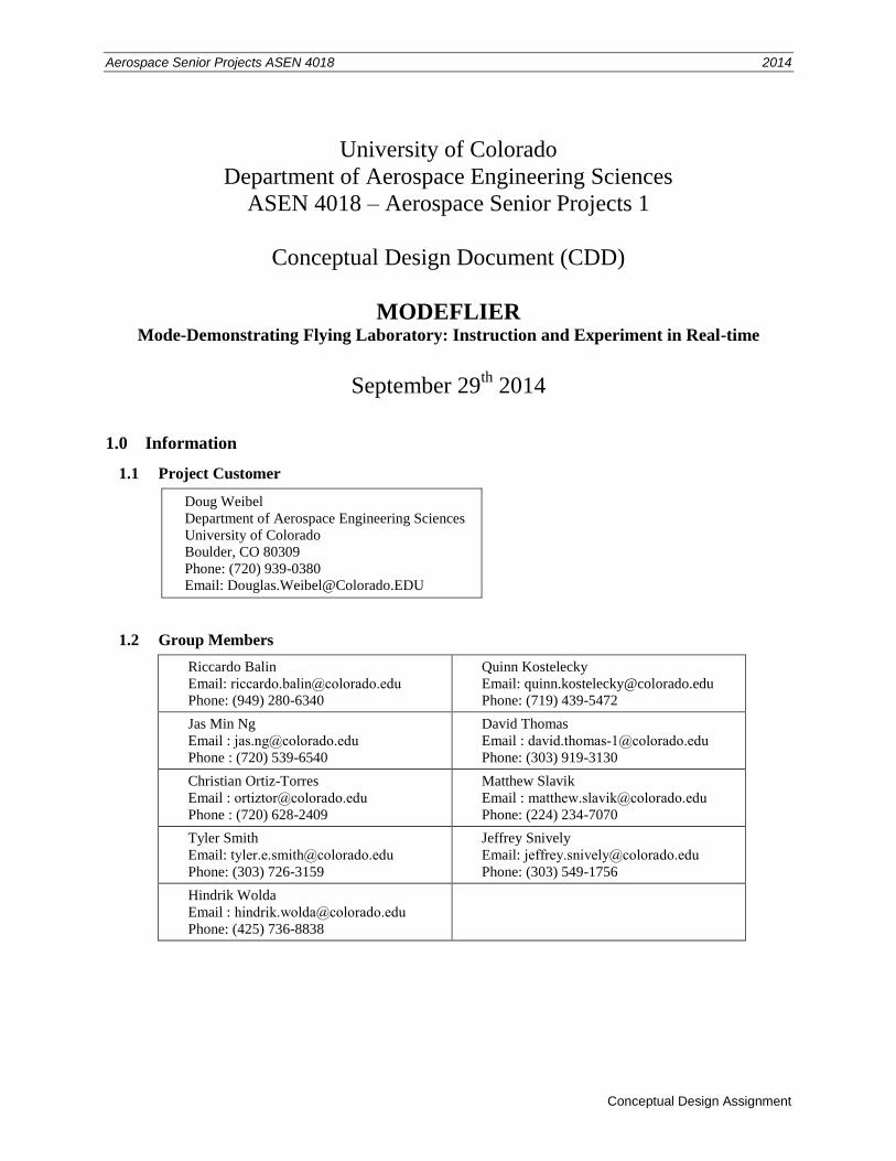
University of Colorado
Department of Aerospace Engineering Sciences
ASEN 4018 – Aerospace Senior Projects 1
Conceptual Design Document (CDD)
MODEFLIER Mode-Demonstrating Flying Laboratory: Instruction and Experiment in Real-time
September 29th
2014
1.0 Information
1.1 Project Customer
Doug Weibel
Department of Aerospace Engineering Sciences
University of Colorado
Boulder, CO 80309
Phone: (720) 939-0380 Email: [email protected]
1.2 Group Members
Riccardo Balin
Email: [email protected]
Phone: (949) 280-6340
Quinn Kostelecky
Email: [email protected]
Phone: (719) 439-5472
Jas Min Ng
Email : [email protected]
Phone : (720) 539-6540
David Thomas
Email : [email protected]
Phone: (303) 919-3130
Christian Ortiz-Torres
Email : [email protected]
Phone : (720) 628-2409
Matthew Slavik
Email : [email protected]
Phone: (224) 234-7070
Tyler Smith
Email: [email protected]
Phone: (303) 726-3159
Jeffrey Snively
Email: [email protected]
Phone: (303) 549-1756
Hindrik Wolda
Email : [email protected]
Phone: (425) 736-8838
Conceptual Design Document 2014 Aerospace Senior Projects ASEN 4018
2
2.0 Project Description
The MODEFLIER system will be a flying laboratory that will serve to demonstrate the phugoid, spiral and
Dutch roll modes of an aircraft for the ASEN 3128 course. This section outlines the purpose, objectives, operational
concepts, functional requirements, and critical project elements of this project.
2.1 Purpose
The flight dynamics of a conventional aircraft are highly complex and nonlinear. In order to model these
dynamics they are often linearized, resulting in approximations of the characteristic aircraft longitudinal and lateral
modes, namely the phugoid, short-period, roll, Dutch roll, and spiral modes. The complexity of the equations
defining these modes makes it difficult to conceptualize the physical effects a perturbation has on the motion of the
aircraft. Additionally, the natural flight modes of an aircraft are hard to observe, due to their brief duration, subtlety,
or both. Software simulations are currently used as a teaching tool for students learning this new material, providing
general insight to the aircraft modes. Nevertheless, simulations do not provide the physical insight that a live
demonstration can offer.
The intent of this project is ultimately to develop a flying system that will benefit future ASEN 3128
students by providing them with a physical and visual demonstration, enhancing their understanding of aircraft
modes beyond what current methods of instruction provide.
2.2 Objectives
The objective for this project is to deliver a small, low-cost, flying system that shall demonstrate the
phugoid, spiral and Dutch roll modes of an aircraft to the junior-level course, ASEN 3128. The flying system shall
be controlled by a remote ground station, which will also display real-time flight data (i.e. aircraft state variables*
plotted against time) at a resolution with respect to a change of 1° for Euler angles, 1 m for position and 0.5 m/s for
velocities. The combined system shall also allow for the ground station operator to switch any of the modes “ON” or
“OFF” during flight. The flying system will record and store video on-board to provide additional perspective for
each aircraft mode. The entire system must also fit in a conventional Sport Utility Vehicle (SUV) with cargo space
of approximately 150 cm x 100 cm x 90 cm, for easy transportation. Finally, the aircraft shall be reproducible for a
maximum of $1,000, and the ground station for a maximum of $2,000.
* The aircraft state variables include inertial position, inertial velocity in body frame, angular velocity in body frame, and Euler
angles1.
Conceptual Design Document 2014 Aerospace Senior Projects ASEN 4018
3
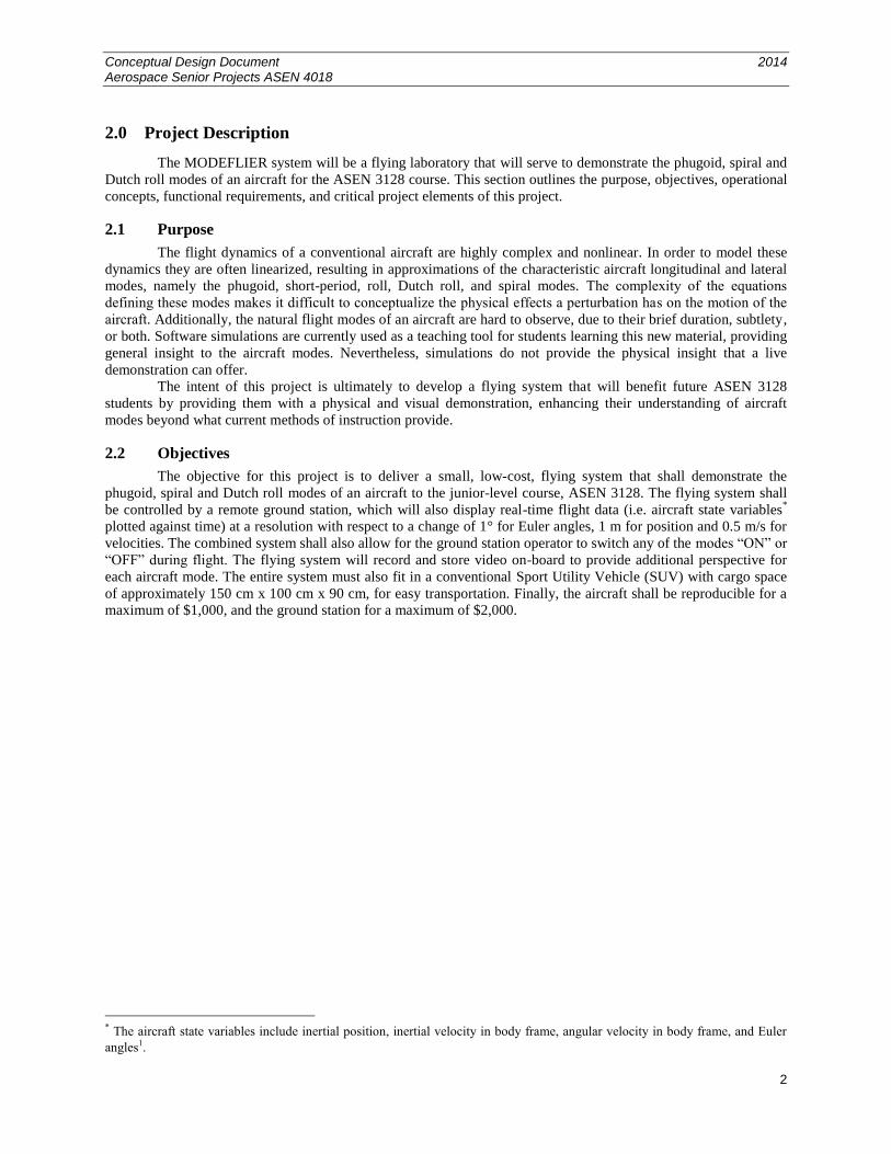
2.3 Concept of Operations (CONOPS)
Outlined in Figure 2.1 is the MODEFLIER system concept of operations. This diagram illustrates how the
customer will eventually use the system to instruct students. A brief description of the CONOPS diagram is included
below.
A/C – Aircraft, GS – Ground Station, LOS – Line of Sight, RC – Radio Controlled, TBD – To be Decided
Figure 2.1: Concept of Operations (CONOPS) Diagram.
1. Transport & Arrival – The aircraft and ground station are transported to the test site in a conventional SUV with
cargo dimensions approximately 150 cm x 100 cm x 90 cm. The aircraft and ground station will fit into a single
container.
2. Setup & Assembly – The aircraft and ground station are removed from the SUV and assembled for the mission.
Both systems will be subjected to functional and safety checks to ensure operational capability before an
attempted flight.
3. Launch & Ascent – The aircraft is launched into the air using a method appropriate to the test environment as
no terrain modifications are permissible. Whether take-off is performed autonomously or by remote pilot
control will be decided in later design documentation; the decision depends on aircraft configuration, test
location, and capabilities of the onboard autopilot.
4. Steady Flight – The aircraft will autonomously follow a predefined flight path at a prescribed altitude. The
footprint of the flight area will be defined such that any flight anomalies will not endanger ground personnel
and/or observers.
5. Mode Demonstration – Each of the three aircraft dynamic modes (phugoid, Dutch roll, and spiral) will be
demonstrated such that they are visible by ground observers. The time at which these mode demonstrations
occur will be commanded from the ground station. Onboard sensors will record the aircraft state variables and
downlink them to the ground system. The ground system shall process this data and display live updating plots
Conceptual Design Document 2014 Aerospace Senior Projects ASEN 4018
4
at a rate of 10 Hz for the observers. Additionally, an onboard camera will collect video of the flight and store it
onboard for download at a later time. If at any point during steps 3, 4, or 5 a flight anomaly occurs, an
experienced pilot will have the capability of overriding the autopilot with Radio Controlled (RC) commands in
order to recover the aircraft to a steady flight path or land the aircraft safely away from ground personnel.
6. Descent and Landing – The aircraft will land on the ground with a method appropriate for the test environment
as no terrain modifications are permitted. Whether landing is performed autonomously or by remote pilot
control will be decided in later design documentation; the decision depends on aircraft configuration, test
location, and capabilities of the onboard autopilot. Steps 3-6 (or subsets of these steps) can be repeated for a
class of approximately 40 students in 110 minutes (duration of ASEN 3128 lab) such that every student will be
able to view the ground station display at least one time during each of the three different aircraft mode
demonstrations.
7. Disassembly – The aircraft and ground station will be disassembled and placed in the SUV. Checks will be
performed to ensure every component of the aircraft and ground station are accounted for. The onboard video
will be downloaded from the aircraft and stored for later viewings.
8. Departure – The entire system will be returned to the customer’s desired location to store the aircraft and
ground station until the next mission.
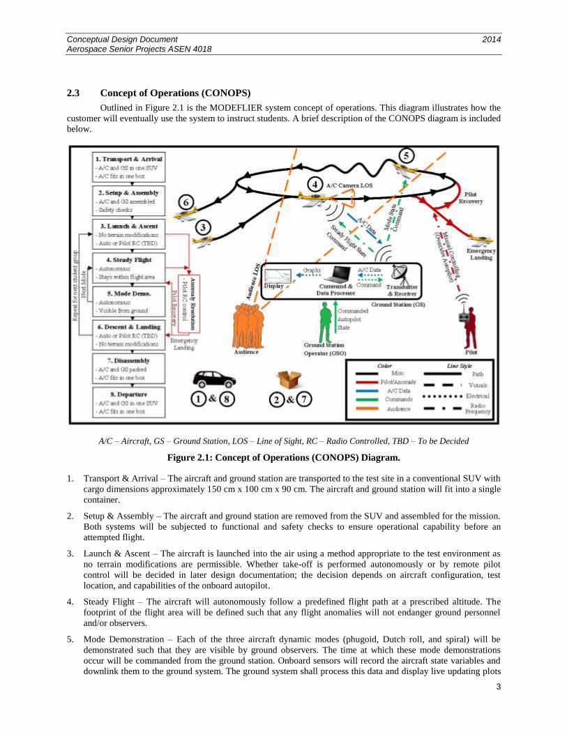
2.4 Functional Block Diagram
The MODEFLIER project consists of two primary components: the aircraft and the ground station. Figure
2.2 shows these systems, their components, their interaction with each other, operational personnel, and the
audience.
GS – Ground Station, RC – Radio Controlled
Figure 2.2: Functional Block Diagram (FBD)
A few key takeaways from the Functional Block Diagram are:
The MODEFLIER system consists of the aircraft and the ground station. These two systems communicate
through Radio-Frequency (RF) signals, where the ground station uplinks commands and the aircraft downlinks
telemetry.
All aircraft subsystems (with the exception of the video camera) will be routed through the flight computer. The
flight control computer will take into account ground commands and (aircraft state) sensor readings to
Conceptual Design Document 2014 Aerospace Senior Projects ASEN 4018
5
determine the proper response in the form of control surface positioning. The flight computer will communicate
with an onboard autopilot; the type and form of communication between the flight computer and the autopilot
will be determined by the type and capabilities of the autopilot.
The ground station can command the aircraft by two distinctly different methods. The first method is performed
by the autopilot control system which will tell the flight computer the general behavior the aircraft should
display (e.g. steady flight in a specific flight path). The aircraft behavior will be input into the system by a
ground station operator. The second method is accomplished by a handheld transmitter where the pilot can
directly command control surface deflections of the aircraft via RC. The method of commanding will be
determined by a control switch that the pilot can toggle between the two methods.
The ground station will also process downlinked aircraft state variables and display them graphically for the
observers. The observers will also be able to view the aircraft directly by viewing the physical aircraft as it
demonstrates each mode.
The boxes named “Aircraft Battery” and “Ground Station Power” indicate the power sources of the two
components. All components with the lightning symbol are powered by the source corresponding to the same
color indication. No lines were extended from the power source boxes to the other components to reduce clutter
in the diagram.
2.5 Critical Project Elements
2.5.1 Technical Elements
2.5.1.1 Phugoid, spiral, and Dutch roll mode demonstration
It is vital to the success of this project for the aircraft to be able to exhibit the phugoid, spiral, and Dutch
roll modes in a manner that is clearly visible from an audience located on the ground. This requirement constitutes
an unusual design driver for the airframe as most aircraft and control systems are designed to be very stable whereas
this project intends to make the aircraft very close to neutral stability in several modes. Moreover, it is central to all
the other functional requirements and to the objective of the project.
2.5.1.2 Autopilot design
The aircraft must fly autonomously, and the modes are to be triggered during flight by a method
commanded from the ground station. Not only is this project element necessary for the complete success of the
system, but it also requires a large amount of time and expertise due to the fact that the aircraft will be required to do
more than fly in a fixed flight pattern, as most autopilots do. This system must be able to integrate with the mode
excitation method. The autopilot will most likely be purchased, but will have to be significantly modified for the
purposes of this project.
2.5.1.3 Ground station electronics and communication
The ground station is inherently tied to success of the mission as it must handle commanding, pilot RC
manual override, telemetry downlink, processing, and display. It is an aspect of the project that carries high risk and
is required to be highly reliable (e.g. if the pilot RC manual override fails, there are significant safety concerns).
Additionally, there are no team members that carry much communication or electronic experience, making the
ground system and communications a particularly involved challenge.
2.5.2 Logistical Elements
2.5.2.1 FAA approval
As a flying, unmanned vehicle, the aircraft must meet the criteria for Federal Aviation Administration
(FAA) authorization for commercial autonomous outdoor flight. This process of obtaining a Certificate of
Authorization (COA) takes time and introduces a large amount of risk and uncertainty for the design strategy to
adopt. In addition, no team member has experience with the process.
Conceptual Design Document 2014 Aerospace Senior Projects ASEN 4018
6
2.5.2.2 Location
A suitable flight location for the aircraft must be determined and acquired. Due to FAA restrictions, limited
time, and availability of flight locations, several feasible options will need to be considered, including both indoor
and outdoor locations. The flight location is a critical component that will drive the method adopted for testing and
validation of the functional requirements, as well as the aircraft design. In addition, its uncertainty adds a
considerable amount of risk to the project.
2.5.3 Financial Elements
There are financial constraints on the reproducible costs of the airframe and the ground station—$1,000
and $2,000, respectively—but at this time these constraints are not considered to be critical.
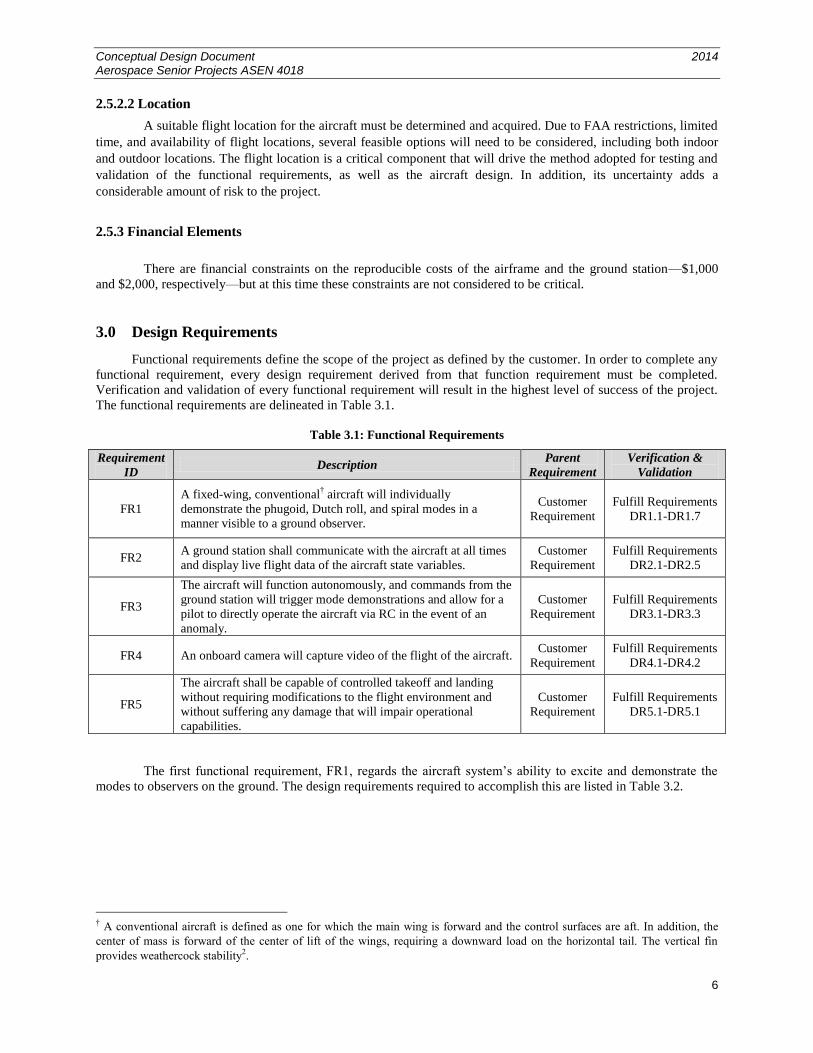
3.0 Design Requirements
Functional requirements define the scope of the project as defined by the customer. In order to complete any
functional requirement, every design requirement derived from that function requirement must be completed.
Verification and validation of every functional requirement will result in the highest level of success of the project.
The functional requirements are delineated in Table 3.1.
Table 3.1: Functional Requirements
Requirement
ID Description
Parent
Requirement
Verification &
Validation
FR1
A fixed-wing, conventional† aircraft will individually
demonstrate the phugoid, Dutch roll, and spiral modes in a
manner visible to a ground observer.
Customer
Requirement
Fulfill Requirements
DR1.1-DR1.7
FR2 A ground station shall communicate with the aircraft at all times
and display live flight data of the aircraft state variables.
Customer
Requirement
Fulfill Requirements
DR2.1-DR2.5
FR3
The aircraft will function autonomously, and commands from the
ground station will trigger mode demonstrations and allow for a
pilot to directly operate the aircraft via RC in the event of an
anomaly.
Customer
Requirement
Fulfill Requirements
DR3.1-DR3.3
FR4 An onboard camera will capture video of the flight of the aircraft. Customer
Requirement
Fulfill Requirements
DR4.1-DR4.2
FR5
The aircraft shall be capable of controlled takeoff and landing
without requiring modifications to the flight environment and
without suffering any damage that will impair operational
capabilities.
Customer
Requirement
Fulfill Requirements
DR5.1-DR5.1
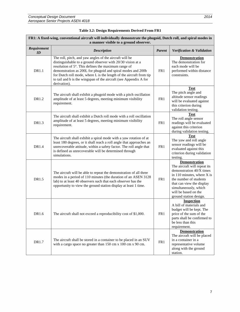
The first functional requirement, FR1, regards the aircraft system’s ability to excite and demonstrate the
modes to observers on the ground. The design requirements required to accomplish this are listed in Table 3.2.
† A conventional aircraft is defined as one for which the main wing is forward and the control surfaces are aft. In addition, the
center of mass is forward of the center of lift of the wings, requiring a downward load on the horizontal tail. The vertical fin
provides weathercock stability2.
Conceptual Design Document 2014 Aerospace Senior Projects ASEN 4018
7
Table 3.2: Design Requirements Derived From FR1
FR1: A fixed-wing, conventional aircraft will individually demonstrate the phugoid, Dutch roll, and spiral modes in
a manner visible to a ground observer.
Requirement
ID Description Parent Verification & Validation
DR1.1
The roll, pitch, and yaw angles of the aircraft will be
distinguishable to a ground observer with 20/30 vision at a
resolution of 5°. This defines the maximum range of
demonstration as 200L for phugoid and spiral modes and 200b
for Dutch roll mode, where L is the length of the aircraft from tip
to tail and b is the wingspan of the aircraft (see Appendix A for
derivation).
FR1
Demonstration
The demonstration for
each mode will be
performed within distance
constraints.
DR1.2
The aircraft shall exhibit a phugoid mode with a pitch oscillation
amplitude of at least 5 degrees, meeting minimum visibility
requirement.
FR1
Test
The pitch angle and
altitude sensor readings
will be evaluated against
this criterion during
validation testing.
DR1.3
The aircraft shall exhibit a Dutch roll mode with a roll oscillation
amplitude of at least 5 degrees, meeting minimum visibility
requirement.
FR1
Test
The roll angle sensor
readings will be evaluated
against this criterion
during validation testing.
DR1.4
The aircraft shall exhibit a spiral mode with a yaw rotation of at
least 180 degrees, or it shall reach a roll angle that approaches an
unrecoverable attitude, within a safety factor. The roll angle that
is defined as unrecoverable will be determined through
simulations.
FR1
Test
The yaw and roll angle
sensor readings will be
evaluated against this
criterion during validation
testing.
DR1.5
The aircraft will be able to repeat the demonstration of all three
modes in a period of 110 minutes (the duration of an ASEN 3128
lab) to at least 40 observers such that each observer has the
opportunity to view the ground station display at least 1 time.
FR1
Demonstration
The aircraft will repeat its
demonstration 40/X times
in 110 minutes, where X is
the number of students
that can view the display
simultaneously, which
will be based on the
ground station design.
DR1.6 The aircraft shall not exceed a reproducibility cost of $1,000. FR1
Inspection
A bill of materials and
budget will be kept. The
price of the sum of the
parts shall be confirmed to
be less than this
requirement.
DR1.7 The aircraft shall be stored in a container to be placed in an SUV
with a cargo space no greater than 150 cm x 100 cm x 90 cm. FR1
Demonstration
The aircraft will be placed
in a container in a
representative volume
along with the ground
station.
Conceptual Design Document 2014 Aerospace Senior Projects ASEN 4018
8
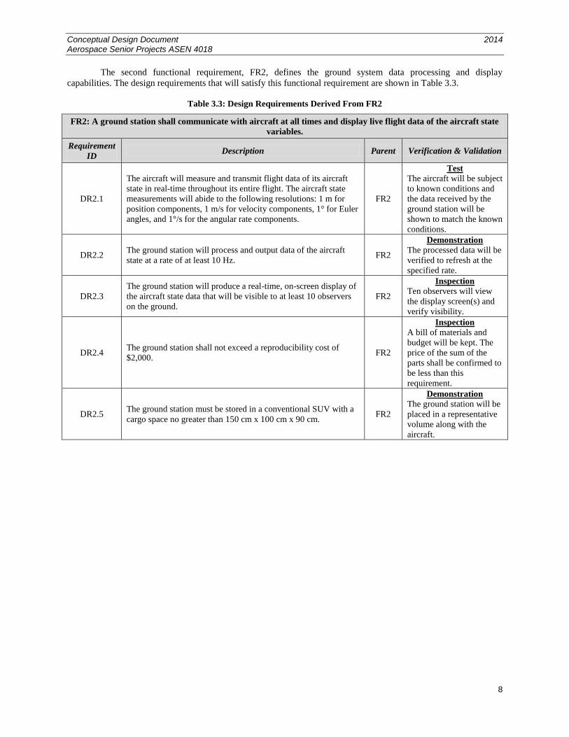
The second functional requirement, FR2, defines the ground system data processing and display
capabilities. The design requirements that will satisfy this functional requirement are shown in Table 3.3.
Table 3.3: Design Requirements Derived From FR2
FR2: A ground station shall communicate with aircraft at all times and display live flight data of the aircraft state
variables.
Requirement
ID Description Parent Verification & Validation
DR2.1
The aircraft will measure and transmit flight data of its aircraft
state in real-time throughout its entire flight. The aircraft state
measurements will abide to the following resolutions: 1 m for
position components, 1 m/s for velocity components, 1° for Euler
angles, and 1°/s for the angular rate components.
FR2
Test
The aircraft will be subject
to known conditions and
the data received by the
ground station will be
shown to match the known
conditions.
DR2.2 The ground station will process and output data of the aircraft
state at a rate of at least 10 Hz. FR2
Demonstration
The processed data will be
verified to refresh at the
specified rate.
DR2.3
The ground station will produce a real-time, on-screen display of
the aircraft state data that will be visible to at least 10 observers
on the ground.
FR2
Inspection
Ten observers will view
the display screen(s) and
verify visibility.
DR2.4 The ground station shall not exceed a reproducibility cost of
$2,000. FR2
Inspection
A bill of materials and
budget will be kept. The
price of the sum of the
parts shall be confirmed to
be less than this
requirement.
DR2.5 The ground station must be stored in a conventional SUV with a
cargo space no greater than 150 cm x 100 cm x 90 cm. FR2
Demonstration
The ground station will be
placed in a representative
volume along with the
aircraft.
Conceptual Design Document 2014 Aerospace Senior Projects ASEN 4018
9
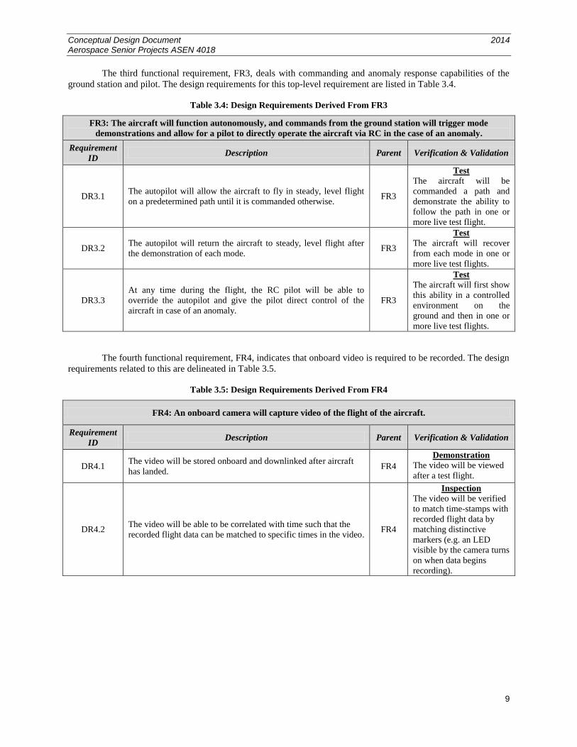
The third functional requirement, FR3, deals with commanding and anomaly response capabilities of the
ground station and pilot. The design requirements for this top-level requirement are listed in Table 3.4.
Table 3.4: Design Requirements Derived From FR3
FR3: The aircraft will function autonomously, and commands from the ground station will trigger mode
demonstrations and allow for a pilot to directly operate the aircraft via RC in the case of an anomaly.
Requirement
ID Description Parent Verification & Validation
DR3.1 The autopilot will allow the aircraft to fly in steady, level flight
on a predetermined path until it is commanded otherwise. FR3
Test
The aircraft will be
commanded a path and
demonstrate the ability to
follow the path in one or
more live test flight.
DR3.2 The autopilot will return the aircraft to steady, level flight after
the demonstration of each mode. FR3
Test
The aircraft will recover
from each mode in one or
more live test flights.
DR3.3
At any time during the flight, the RC pilot will be able to
override the autopilot and give the pilot direct control of the
aircraft in case of an anomaly.
FR3
Test
The aircraft will first show
this ability in a controlled
environment on the
ground and then in one or
more live test flights.
The fourth functional requirement, FR4, indicates that onboard video is required to be recorded. The design
requirements related to this are delineated in Table 3.5.
Table 3.5: Design Requirements Derived From FR4
FR4: An onboard camera will capture video of the flight of the aircraft.
Requirement
ID Description Parent Verification & Validation
DR4.1 The video will be stored onboard and downlinked after aircraft
has landed. FR4
Demonstration
The video will be viewed
after a test flight.
DR4.2 The video will be able to be correlated with time such that the
recorded flight data can be matched to specific times in the video. FR4
Inspection
The video will be verified
to match time-stamps with
recorded flight data by
matching distinctive
markers (e.g. an LED
visible by the camera turns
on when data begins
recording).
Conceptual Design Document 2014 Aerospace Senior Projects ASEN 4018
10
The fifth functional requirement, FR5, necessitates that the aircraft must be able to take off and land
without modifying the test environment or damaging the airframe. The design requirements for this functional
requirement are displayed in Table 3.6.
Table 3.6: Design Requirements Derived From FR5
FR5: The aircraft shall be capable of takeoff and landing without requiring modifications to the flight environment
and without suffering any damage that will impair operational capabilities.
Requirement
ID Description Parent Verification & Validation
DR5.1
The launch method will be appropriate for the test environment.
The three methods being considered are hand-launched, bungee-
launched, and ground take-off with landing gear. This will be
highly dependent on the selected airframe.
FR5
Demonstration
The aircraft can
successfully take-off.
DR5.2
The landing method will also be appropriate for the test
environment. Methods considered will include landing gear and
controlled belly-landing. This will be highly dependent on the
selected airframe.
FR5
Demonstration
The aircraft can
successfully land
4.0 Key Design Options Considered
4.1 Aircraft Configuration
For the MODEFLIER to be successful, its stability characteristics must be evaluated and optimized to
perform the phugoid, Dutch roll and spiral modes. This does not mean that the MODEFLIER will have great
stability, rather it will actually need to have relatively poor stability; otherwise the natural modes might not be
distinguishable. In order to design for bad stability, the MODEFLIER’s configuration must be chosen carefully.
As the MODEFLIER will be, by definition, a conventional aircraft, the configuration choices are limited. For an
aircraft to be considered conventional, the aircraft will have a narrow fuselage with a forward-mounted wing and an
aft-mounted empennage, or tail assembly. Between the wing and empennage, there are many design choices to be
considered, each with their own advantages and disadvantages. For this project, the wing and empennage designs
will be chosen independently to find the optimal design for each. If a problem is realized where the design
combination is not feasible or rational, the design options will be reevaluated. Engine configuration is not included
in this study as it is heavily dependent on the result of these studies, and does not impede the requirements.
The configuration investigation will not take into account availability for acquiring the aircraft, either
bought or borrowed. Rather, an optimal configuration will be chosen, and availability will be evaluated afterwards.
It should be noted that the optimal aircraft for this project has been determined to be that which has low stability in
order to adequately demonstrate the natural dynamic modes. For many conventional aircraft, the spiral mode is
unstable but recoverable. The spiral mode response is also a function of flight speed, so it is possible to adjust spiral
stability by changing the cruise velocity. These factors lead to the conclusion that the spiral mode shall not be a main
design driver for the MODEFLIER, while emphasis will be placed on the phugoid and Dutch roll modes. This is
significant because the Dutch roll and spiral modes are affected oppositely by certain aircraft characteristics, such as
the dihedral effect. The dihedral will be designed to optimize the Dutch roll response, although the effect on the
spiral mode will also be taken into consideration when choosing the configuration.
4.1.1 Wing Configuration
A sample has been taken of various RC aircraft and other UAVs to see the available wing configuration
options for the MODEFLIER aircraft. The purpose of this survey is to observe common wing configurations that are
used in conventional aircraft. Four primary types of wing configurations have been identified by this sample: the
mid wing with a large wingspan, the low wing with a dihedral angle, the high wing, and the mid wing with sweep.
These four design options form the basis for the wing configuration trade study.
It is worth noting that the grouping of all of the possible wing configurations into these four categories may
limit the possible design options and so not span the entire design space. However, this grouping has been done for a
couple of reasons. One is the practical reason of keeping the total number of options under consideration down to a
manageable number for a trade study. Furthermore, since these options have been chosen as representative of the
different types of existing aircraft, they do reflect the current types of conventional UAVs. Also, the results of the
Conceptual Design Document 2014 Aerospace Senior Projects ASEN 4018
11
trade study may indicate that two or more of the options can be combined in such a way so as to capture the
advantages of both options, while limiting their disadvantages. In other words, other possible configurations have
not yet been eliminated. The trade study may be repeated to include new design options that arise from the
combination of options that score highly in the first iteration of the study.
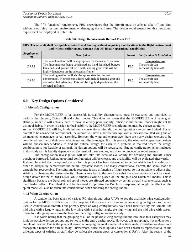
4.1.1.1 Mid Wing with a Large Wingspan
Figure 4.1.1.1: Adagio 280 BNF Basic3
One general type of wing design is characterized by wings in the middle of the fuselage with a large
wingspan and a high aspect ratio. The Adagio 280 BNF Basic illustrates this basic design; it has an aspect ratio of
13. In addition, the wingspan (142 cm) is almost twice the length of the fuselage (76 cm)3. The large wingspan of
this type of aircraft, however, necessitates that there is no (or a very small) dihedral angle, since dihedral decreases
the lift produced by the wings, offsetting the advantage of using large wings4. Furthermore, these wings are usually
unswept, so as to take full advantage of the wingspan and to maximize the lift produced by the wings.
Table 4.1.1.1: Mid Wing with a Large Wingspan Advantages and Disadvantages
Advantages Disadvantages
The high aspect ratio lowers the induced drag,
creating a good lift-to-drag ratio and decreasing
phugoid mode damping.
The large wingspan makes the aircraft harder to store
in specified trunk of an SUV.
The large wing area decreases the necessary speed
needed to produce the same lift, allowing for a slower
trim speed.
The size of the wings prevents the use of many lateral
stability techniques, such as a dihedral angle.
The large wings increase the visibility of the aircraft
to ground observers.
Conceptual Design Document 2014 Aerospace Senior Projects ASEN 4018
12
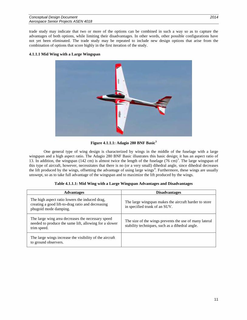
4.1.1.2 Low Wing with Dihedral
Figure 4.1.1.2: F4U Corsair RTF5
Another type of wing configuration under consideration employs wings at the bottom of the fuselage that
possess a significant dihedral angle. One such plane is the F4U Corsair RTF, modeled after the WWII fighter plane5.
The large dihedral angle of this type of aircraft significantly improves the lateral stability of the aircraft through the
stabilizing dihedral effect for roll perturbations. However, large dihedral has also been known to contribute to a
more pronounced Dutch roll mode4. Aircraft with large dihedral angles often have the wings mounted at the bottom
of the fuselage, in contrast to the next type of wing configuration to be considered.
Table 4.1.1.2: Low Wing with Dihedral Advantages and Disadvantages
Advantages Disadvantages
The large dihedral angle increase lateral stability in
response to roll disturbances, which contributes to a
larger Dutch roll mode with less damping.
The dihedral decreases the lift produced and may
require a greater trim speed.
The dihedral of the wings decreases the effective
wingspan and makes storage more manageable.
The low position of the wings relative to the center of
mass slightly limits the lateral stability.
Conceptual Design Document 2014 Aerospace Senior Projects ASEN 4018
13
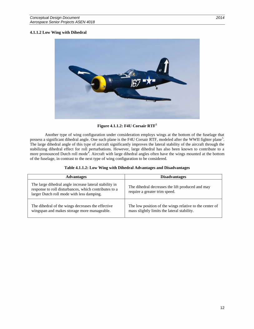
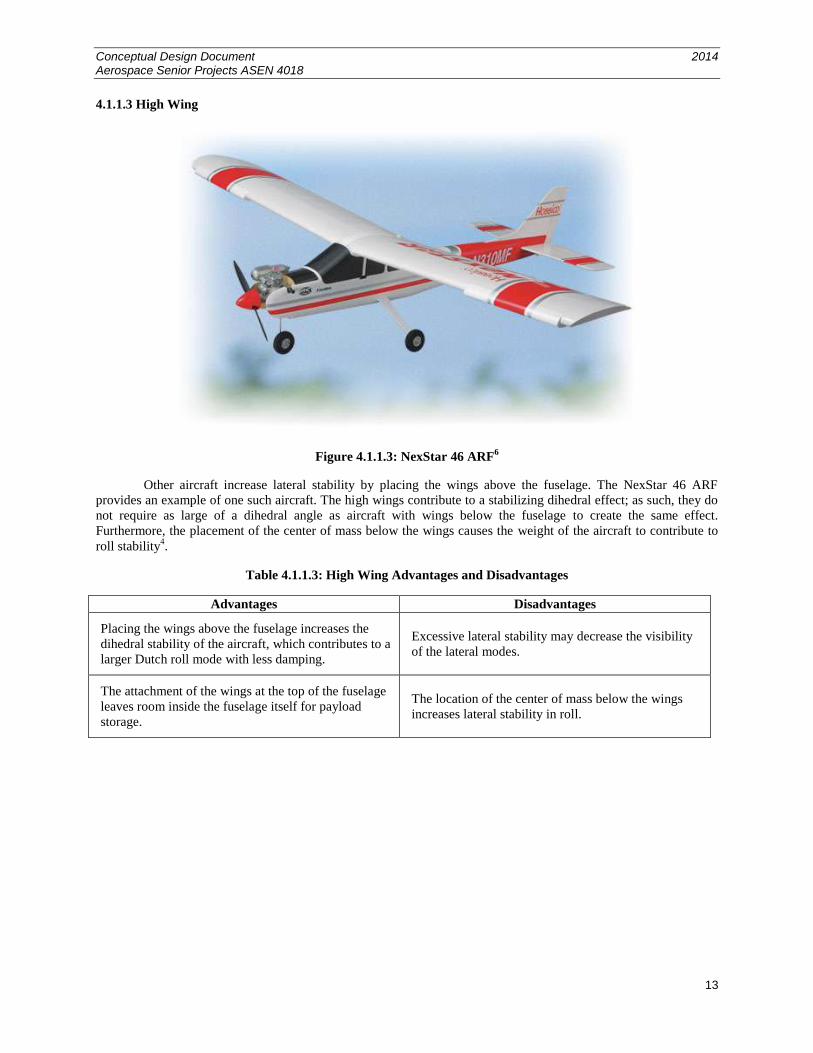
4.1.1.3 High Wing
Figure 4.1.1.3: NexStar 46 ARF6
Other aircraft increase lateral stability by placing the wings above the fuselage. The NexStar 46 ARF
provides an example of one such aircraft. The high wings contribute to a stabilizing dihedral effect; as such, they do
not require as large of a dihedral angle as aircraft with wings below the fuselage to create the same effect.
Furthermore, the placement of the center of mass below the wings causes the weight of the aircraft to contribute to
roll stability4.
Table 4.1.1.3: High Wing Advantages and Disadvantages
Advantages Disadvantages
Placing the wings above the fuselage increases the
dihedral stability of the aircraft, which contributes to a
larger Dutch roll mode with less damping.
Excessive lateral stability may decrease the visibility
of the lateral modes.
The attachment of the wings at the top of the fuselage
leaves room inside the fuselage itself for payload
storage.
The location of the center of mass below the wings
increases lateral stability in roll.
Conceptual Design Document 2014 Aerospace Senior Projects ASEN 4018
14
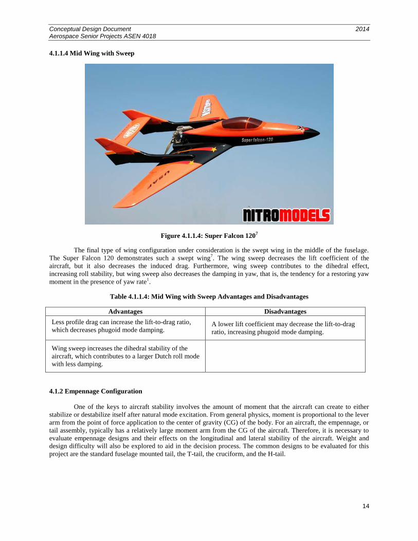
4.1.1.4 Mid Wing with Sweep
Figure 4.1.1.4: Super Falcon 1207
The final type of wing configuration under consideration is the swept wing in the middle of the fuselage.
The Super Falcon 120 demonstrates such a swept wing7. The wing sweep decreases the lift coefficient of the
aircraft, but it also decreases the induced drag. Furthermore, wing sweep contributes to the dihedral effect,
increasing roll stability, but wing sweep also decreases the damping in yaw, that is, the tendency for a restoring yaw
moment in the presence of yaw rate1.
Table 4.1.1.4: Mid Wing with Sweep Advantages and Disadvantages
Advantages Disadvantages
Less profile drag can increase the lift-to-drag ratio,
which decreases phugoid mode damping. A lower lift coefficient may decrease the lift-to-drag
ratio, increasing phugoid mode damping.
Wing sweep increases the dihedral stability of the
aircraft, which contributes to a larger Dutch roll mode
with less damping.
4.1.2 Empennage Configuration
One of the keys to aircraft stability involves the amount of moment that the aircraft can create to either
stabilize or destabilize itself after natural mode excitation. From general physics, moment is proportional to the lever
arm from the point of force application to the center of gravity (CG) of the body. For an aircraft, the empennage, or
tail assembly, typically has a relatively large moment arm from the CG of the aircraft. Therefore, it is necessary to
evaluate empennage designs and their effects on the longitudinal and lateral stability of the aircraft. Weight and
design difficulty will also be explored to aid in the decision process. The common designs to be evaluated for this
project are the standard fuselage mounted tail, the T-tail, the cruciform, and the H-tail.
Conceptual Design Document 2014 Aerospace Senior Projects ASEN 4018
15
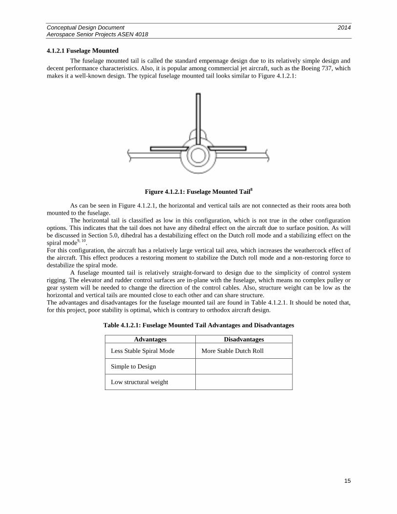
4.1.2.1 Fuselage Mounted
The fuselage mounted tail is called the standard empennage design due to its relatively simple design and
decent performance characteristics. Also, it is popular among commercial jet aircraft, such as the Boeing 737, which
makes it a well-known design. The typical fuselage mounted tail looks similar to Figure 4.1.2.1:
Figure 4.1.2.1: Fuselage Mounted Tail8
As can be seen in Figure 4.1.2.1, the horizontal and vertical tails are not connected as their roots area both
mounted to the fuselage.
The horizontal tail is classified as low in this configuration, which is not true in the other configuration
options. This indicates that the tail does not have any dihedral effect on the aircraft due to surface position. As will
be discussed in Section 5.0, dihedral has a destabilizing effect on the Dutch roll mode and a stabilizing effect on the
spiral mode9, 10
.
For this configuration, the aircraft has a relatively large vertical tail area, which increases the weathercock effect of
the aircraft. This effect produces a restoring moment to stabilize the Dutch roll mode and a non-restoring force to
destabilize the spiral mode.
A fuselage mounted tail is relatively straight-forward to design due to the simplicity of control system
rigging. The elevator and rudder control surfaces are in-plane with the fuselage, which means no complex pulley or
gear system will be needed to change the direction of the control cables. Also, structure weight can be low as the
horizontal and vertical tails are mounted close to each other and can share structure.
The advantages and disadvantages for the fuselage mounted tail are found in Table 4.1.2.1. It should be noted that,
for this project, poor stability is optimal, which is contrary to orthodox aircraft design.
Table 4.1.2.1: Fuselage Mounted Tail Advantages and Disadvantages
Advantages Disadvantages
Less Stable Spiral Mode More Stable Dutch Roll
Simple to Design
Low structural weight
Conceptual Design Document 2014 Aerospace Senior Projects ASEN 4018
16
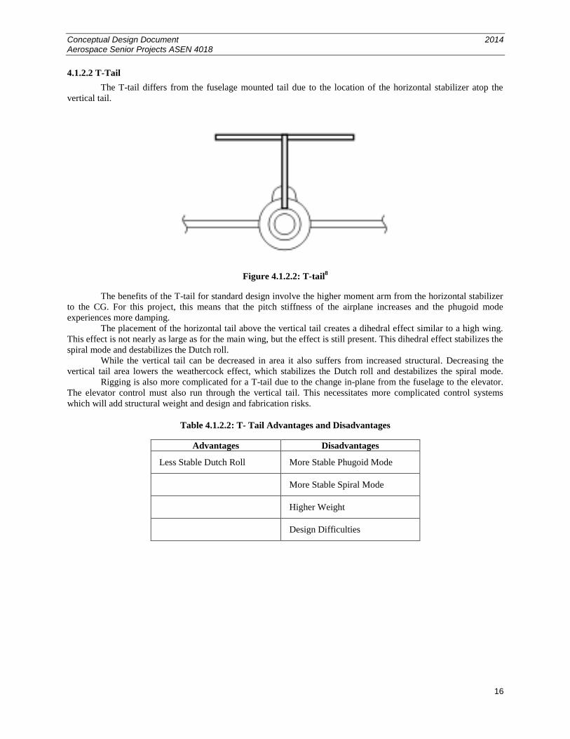
4.1.2.2 T-Tail
The T-tail differs from the fuselage mounted tail due to the location of the horizontal stabilizer atop the
vertical tail.
Figure 4.1.2.2: T-tail8
The benefits of the T-tail for standard design involve the higher moment arm from the horizontal stabilizer
to the CG. For this project, this means that the pitch stiffness of the airplane increases and the phugoid mode
experiences more damping.
The placement of the horizontal tail above the vertical tail creates a dihedral effect similar to a high wing.
This effect is not nearly as large as for the main wing, but the effect is still present. This dihedral effect stabilizes the
spiral mode and destabilizes the Dutch roll.
While the vertical tail can be decreased in area it also suffers from increased structural. Decreasing the
vertical tail area lowers the weathercock effect, which stabilizes the Dutch roll and destabilizes the spiral mode.
Rigging is also more complicated for a T-tail due to the change in-plane from the fuselage to the elevator.
The elevator control must also run through the vertical tail. This necessitates more complicated control systems
which will add structural weight and design and fabrication risks.
Table 4.1.2.2: T- Tail Advantages and Disadvantages
Advantages Disadvantages
Less Stable Dutch Roll More Stable Phugoid Mode
More Stable Spiral Mode
Higher Weight
Design Difficulties
Conceptual Design Document 2014 Aerospace Senior Projects ASEN 4018
17
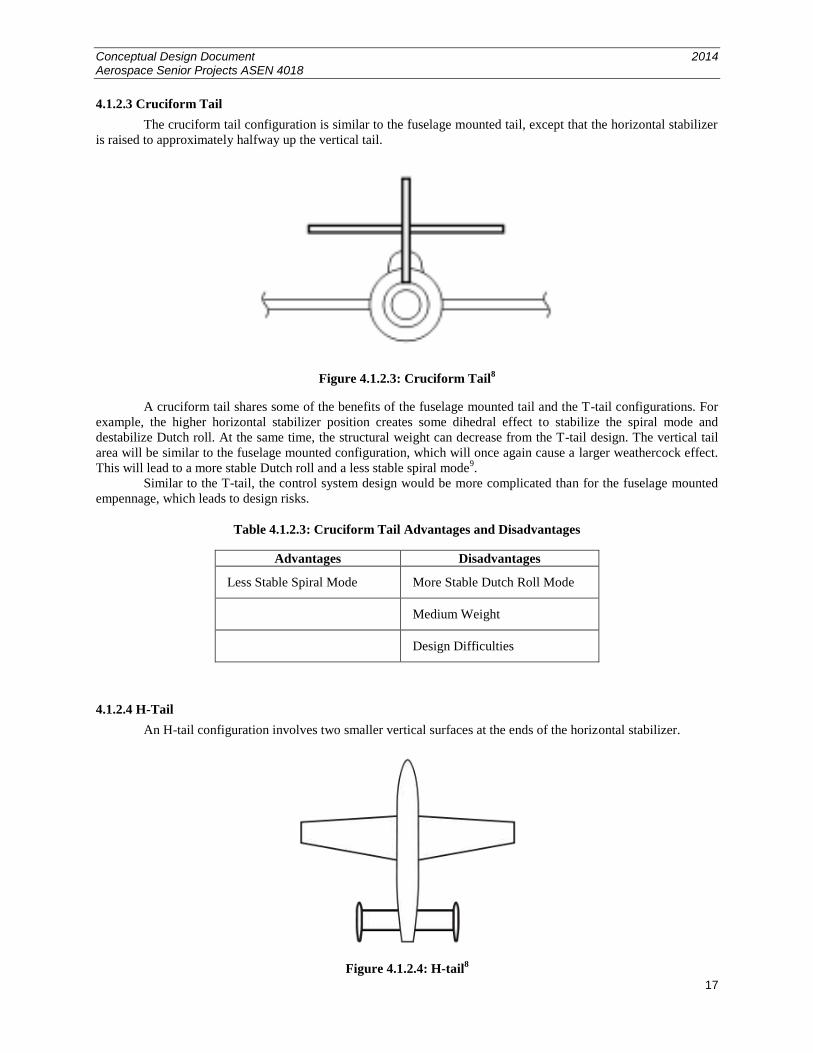
4.1.2.3 Cruciform Tail
The cruciform tail configuration is similar to the fuselage mounted tail, except that the horizontal stabilizer
is raised to approximately halfway up the vertical tail.
Figure 4.1.2.3: Cruciform Tail8
A cruciform tail shares some of the benefits of the fuselage mounted tail and the T-tail configurations. For
example, the higher horizontal stabilizer position creates some dihedral effect to stabilize the spiral mode and
destabilize Dutch roll. At the same time, the structural weight can decrease from the T-tail design. The vertical tail
area will be similar to the fuselage mounted configuration, which will once again cause a larger weathercock effect.
This will lead to a more stable Dutch roll and a less stable spiral mode9.
Similar to the T-tail, the control system design would be more complicated than for the fuselage mounted
empennage, which leads to design risks.
Table 4.1.2.3: Cruciform Tail Advantages and Disadvantages
Advantages Disadvantages
Less Stable Spiral Mode More Stable Dutch Roll Mode
Medium Weight
Design Difficulties
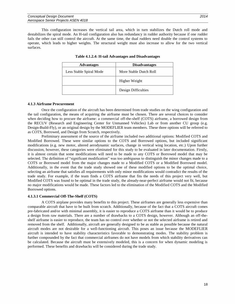
4.1.2.4 H-Tail
An H-tail configuration involves two smaller vertical surfaces at the ends of the horizontal stabilizer.
Figure 4.1.2.4: H-tail8
Conceptual Design Document 2014 Aerospace Senior Projects ASEN 4018
18
This configuration increases the vertical tail area, which in turn stabilizes the Dutch roll mode and
destabilizes the spiral mode. An H-tail configuration also has redundancy in rudder authority because if one rudder
fails the other can still control the aircraft. At the same time, the dual rudders need double the control systems to
operate, which leads to higher weights. The structural weight must also increase to allow for the two vertical
surfaces.
Table 4.1.2.4: H-tail Advantages and Disadvantages
Advantages Disadvantages
Less Stable Spiral Mode More Stable Dutch Roll
Higher Weight
Design Difficulties
4.1.3 Airframe Procurement
Once the configuration of the aircraft has been determined from trade studies on the wing configuration and
the tail configuration, the means of acquiring the airframe must be chosen. There are several choices to consider
when deciding how to procure the airframe: a commercial off-the-shelf (COTS) airframe, a borrowed design from
the RECUV (Research and Engineering Center for Unmanned Vehicles) Lab or from another CU group (e.g.
Design-Build-Fly), or an original design by the MODEFLIER team members. These three options will be referred to
as COTS, Borrowed, and Design from Scratch, respectively.
Preliminary assessment of the source of the airframe included two additional options: Modified COTS and
Modified Borrowed. These were similar options to the COTS and Borrowed options, but included significant
modifications (e.g. new motor, altered aerodynamic surfaces, change in vertical wing location, etc.) Upon further
discussion, however, these categories were eliminated for this study to be evaluated in later documentation. Firstly,
it is almost certain that some modifications will need to be made to any COTS or Borrowed model that may be
selected. The definition of “significant modification” was too ambiguous to distinguish the minor changes made to a
COTS or Borrowed model from the major changes made to a Modified COTS or a Modified Borrowed model.
Additionally, in the event that the trade study showed one of these modified options to be the optimal choice,
selecting an airframe that satisfies all requirements with only minor modifications would contradict the results of the
trade study. For example, if the team finds a COTS airframe that fits the needs of this project very well, but
Modified COTS was found to be optimal in the trade study, the already-near-perfect airframe would not fit, because
no major modifications would be made. These factors led to the elimination of the Modified COTS and the Modified
Borrowed options.
4.1.3.1 Commercial Off-The-Shelf (COTS)
A COTS airplane provides many benefits to this project. These airframes are generally less expensive than
comparable aircraft that have to be built from scratch. Additionally, because of the fact that a COTS aircraft comes
pre-fabricated and/or with minimal assembly, it is easier to reproduce a COTS airframe than it would be to produce
a design from raw materials. There are a number of drawbacks to a COTS design, however. Although an off-the-
shelf airframe is easier to reproduce, the team has no control over whether or not the selected airframe is retired and
removed from the shelf. Additionally, aircraft are generally designed to be as stable as possible because the natural
aircraft modes are not desirable for a well-functioning aircraft. This poses an issue because the MODEFLIER
aircraft is intended to have stability characteristics favorable to demonstrating modes. The stability problem is
further compounded by the fact that commercial airframes do not have models from which stability derivatives can
be calculated. Because the aircraft must be extensively modeled, this is a concern for when dynamic modeling is
performed. These benefits and drawbacks will be considered during the trade study.
Conceptual Design Document 2014 Aerospace Senior Projects ASEN 4018
19
Table 4.1.3.1: COTS Airframe Advantages and Disadvantages
Advantages Disadvantages
Comparably inexpensive Potential for discontinuation
Minimal or no assembly Typically highly stable
Easy to reproduce Difficult to model, no included
model simulations
Large selection variety
Airworthiness is known
4.1.3.2 Borrowed Design
A design that has been borrowed from another team affiliated with CU – notable teams include the RECUV
Lab and the Design-Build-Fly (DBF) club – is also a potential option. A borrowed design may likely already have
models from which stability derivatives can be determined. On top of this, the design already exists and its
airworthiness has already been proven. Unfortunately, borrowed designs have similar drawbacks as the COTS
airframe in that high stability is a desirable trait for these aircraft, and as such, a borrowed design would potentially
be unable to meet the mode demonstration requirements. A borrowed design also must be fabricated by the team
rather than simply buying an airframe, so the reliability of a borrowed design cannot be proven immediately.
Table 4.1.3.2: Borrowed Design Advantages and Disadvantages
Advantages Disadvantages
Potential for model
simulations to be included
with the design
Small selection variety
Typically highly stable
Potential for high material cost
Fabrication required
Airworthiness relies on
successful fabrication
4.1.3.3 Design from Scratch
The last acquisition method is the option to design the aircraft from scratch. The most notable advantage
that comes from designing an original airframe is the extreme freedom of design choices. From sizing to
aerodynamic stability, the choices are limitless. That being said, the most notable disadvantage is the extremely high
workload this imposes on the team. If every facet of the airframe is considered, it means conducting many trade
studies. Just the development of these trade studies would require a lot of time to research on aircraft design and
stability, not to mention the extra research to assign values and actually conduct the trade study. Because the
potential design is so open ended, the cost of materials and fabrication could vary widely based on the nature of the
design. Even a design with inexpensive materials could quickly escalate in cost as the design is modified and edited.
The airworthiness of the design would need to be evaluated as well. Dynamic modeling of an original design would
be straightforward, since model simulations of the aircraft would be developed prior to fabrication. Reproduction of
an original design would be dependent on the nature of the design itself. It could range from a wide range of
difficulty, but full fabrication will be required regardless.
Conceptual Design Document 2014 Aerospace Senior Projects ASEN 4018
20
Table 4.1.3.3: Borrowed Design Advantages and Disadvantages
Advantages Disadvantages
Freedom to make all design
choices of the airframe
Extremely high work load:
design and fabrication
Model simulations developed
simultaneously with the design
Airworthiness relies on
successful design and successful
fabrication
Potential for high material cost
Potential for difficult
reproducibility
4.2 Mode Excitation
A critical aspect of this project is to demonstrate three natural aircraft dynamical modes: the phugoid mode,
spiral mode, and Dutch roll mode. This section proposes different methods to excite these natural modes as the
MODEFLIER aircraft is in flight. The methods of mode excitation analyzed in this study are the use of unstable
control gains with a stable aircraft, an unstable aircraft (without considering control feedback), autopilot control
surface impulse, and RC control surface impulse.
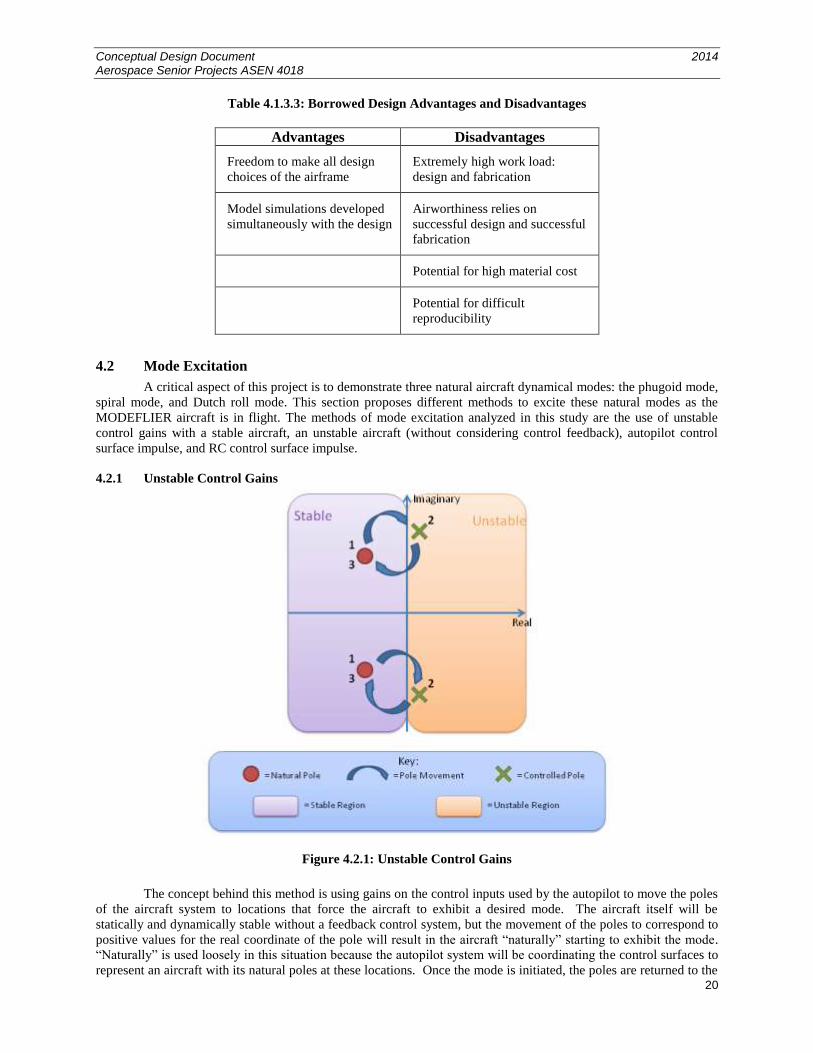
4.2.1 Unstable Control Gains
Figure 4.2.1: Unstable Control Gains
The concept behind this method is using gains on the control inputs used by the autopilot to move the poles
of the aircraft system to locations that force the aircraft to exhibit a desired mode. The aircraft itself will be
statically and dynamically stable without a feedback control system, but the movement of the poles to correspond to
positive values for the real coordinate of the pole will result in the aircraft “naturally” starting to exhibit the mode.
“Naturally” is used loosely in this situation because the autopilot system will be coordinating the control surfaces to
represent an aircraft with its natural poles at these locations. Once the mode is initiated, the poles are returned to the
Conceptual Design Document 2014 Aerospace Senior Projects ASEN 4018
21
natural values of the aircraft and the physical response is allowed to dampen out the oscillations. The coupled nature
of aircraft stability modes produces a difficult situation using this method: implementing a particular control gain
input might cause multiple mode poles to lie in the positive real plane. If multiple modes occur simultaneously, the
physical response will be difficult to identify as one particular mode and therefore incapable of satisfying functional
requirement FR1.
Table 4.2.1: Unstable Control Gains Advantages and Disadvantages
Advantages Disadvantages
Having unstable control gains will allow the
aircraft to go into each of the modes: phugoid,
Dutch roll, and spiral.
Coupled modes will be harder to distinguish with
general control gain input.
Likely to stimulate multiple modes at once.
Risk for the aircraft to go into uncontrollable
flight.
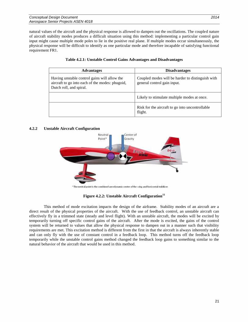
4.2.2 Unstable Aircraft Configuration
Figure 4.2.2: Unstable Aircraft Configuration11
This method of mode excitation impacts the design of the airframe. Stability modes of an aircraft are a
direct result of the physical properties of the aircraft. With the use of feedback control, an unstable aircraft can
effectively fly in a trimmed state (steady and level flight). With an unstable aircraft, the modes will be excited by
temporarily turning off specific control gains of the aircraft. After the mode is excited, the gains of the control
system will be returned to values that allow the physical response to dampen out in a manner such that visibility
requirements are met. This excitation method is different from the first in that the aircraft is always inherently stable
and can only fly with the use of constant control in a feedback loop. This method turns off the feedback loop
temporarily while the unstable control gains method changed the feedback loop gains to something similar to the
natural behavior of the aircraft that would be used in this method.
Conceptual Design Document 2014 Aerospace Senior Projects ASEN 4018
22
Table 4.2.2: Unstable Aircraft Advantages and Disadvantages
Advantages Disadvantages
The modes being demonstrated will happen
naturally without the need of an impulse.
Due to the instability of the aircraft, it could
potentially run into the problem of not being able
to recover from a mode.
The concept of the natural modes is better
understood by the observers since it happens
naturally.
An unstable configuration does not guarantee to
achieve the desired attitude as required for each
of the modes.
Has the potential to cause difficulties in take-off
and landing.
Will be extremely difficult for a pilot to safely fly
and land using RC.
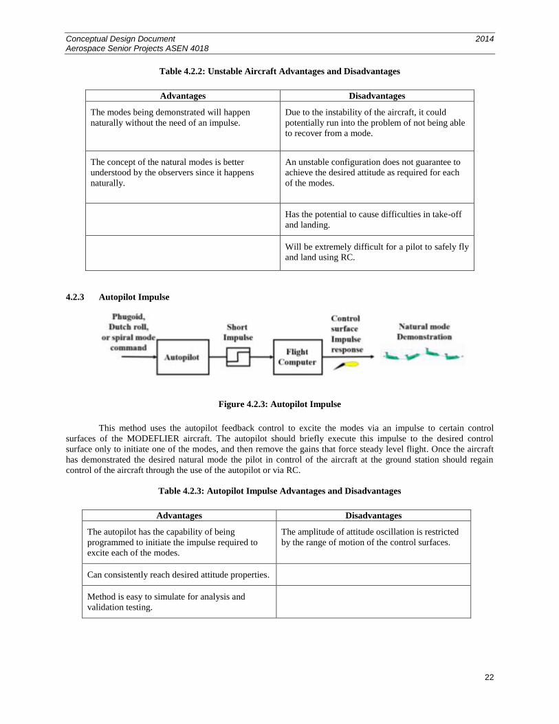
4.2.3 Autopilot Impulse
Figure 4.2.3: Autopilot Impulse
This method uses the autopilot feedback control to excite the modes via an impulse to certain control
surfaces of the MODEFLIER aircraft. The autopilot should briefly execute this impulse to the desired control
surface only to initiate one of the modes, and then remove the gains that force steady level flight. Once the aircraft
has demonstrated the desired natural mode the pilot in control of the aircraft at the ground station should regain
control of the aircraft through the use of the autopilot or via RC.
Table 4.2.3: Autopilot Impulse Advantages and Disadvantages
Advantages Disadvantages
The autopilot has the capability of being
programmed to initiate the impulse required to
excite each of the modes.
The amplitude of attitude oscillation is restricted
by the range of motion of the control surfaces.
Can consistently reach desired attitude properties.
Method is easy to simulate for analysis and
validation testing.
Conceptual Design Document 2014 Aerospace Senior Projects ASEN 4018
23
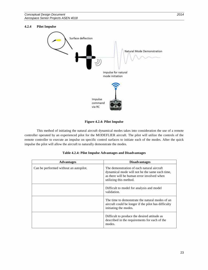
4.2.4 Pilot Impulse
Figure 4.2.4: Pilot Impulse
This method of initiating the natural aircraft dynamical modes takes into consideration the use of a remote
controller operated by an experienced pilot for the MODEFLIER aircraft. The pilot will utilize the controls of the
remote controller to execute an impulse on specific control surfaces to initiate each of the modes. After the quick
impulse the pilot will allow the aircraft to naturally demonstrate the modes.
Table 4.2.4: Pilot Impulse Advantages and Disadvantages
Advantages Disadvantages
Can be performed without an autopilot. The demonstration of each natural aircraft
dynamical mode will not be the same each time,
as there will be human error involved when
utilizing this method.
Difficult to model for analysis and model
validation.
The time to demonstrate the natural modes of an
aircraft could be longer if the pilot has difficulty
initiating the modes.
Difficult to produce the desired attitude as
described in the requirements for each of the
modes.

Conceptual Design Document 2014 Aerospace Senior Projects ASEN 4018
24
4.3 Ground Station
Functional requirement 2 (FR2) for the ground station states that a ground station shall communicate with
the aircraft at all times, and it must display flight data of the aircraft state variables in real-time. From this top level
requirement, four design requirements were derived, which specify the maximum allowed size, the reproducibility
cost of the system, the rate at which flight data must be processed and displayed, and the minimum number of
observers that must be able to simultaneously see the flight data display (See Table 3.3 for detailed description).
Given these requirements, four different design options were taken into consideration. The distinction between them
was based on the idea of creating multiple ground station systems performing the same task in different ways.
It should be noted that aspects of the design such as the processing unit, transceiver, antenna type, and
navigation method were deemed to be too specific and low-level for the purpose of this document. However, the
trade studies on all of those aspects will be conducted in later documentation. In addition, three different
communication media were taken into consideration before developing the design options. These were laser, fiber
optic cables, and radio waves. Research suggested that for this particular project, the most convenient
communication media is radio waves, thus every design option assumes communication between ground and the
aircraft is done via electromagnetic radiation2. Moreover, it was concluded that the more efficient method for
displaying the flight data consisting of the 12 aircraft state variables is in the form of plots as a function of time.
Finally, for safety reasons, it was established that the aircraft would not be flying over the audience, but to the side,
allowing room for an emergency landing in case of anomaly.
4.3.1 Conventional Ground Station
Figure 4.3.1: Conventional ground station
For this design option, the ground station consists of a data processor, a transceiver, the RC control for the
pilot, and two monitors for data display. The transceiver is necessary in order to provide a real-time communication
link between the aircraft and the ground station. This link involves both uplink of commands from the ground to the
vehicle, and the downlink of the aircraft state variables from the vehicle to the ground. The raw data transmitted will
Conceptual Design Document 2014 Aerospace Senior Projects ASEN 4018
25
be processed and stored in real-time by the processing unit, which is also capable of sending commands to the
vehicle via the transceiver. Data processing involves manipulating the raw data to obtain other derived parameters,
as well as manipulating it and organizing it so that it is presented in form of a plot varying over time. The graphs of
the relevant flight data (e.g. pitch, forward speed, height, and pitch rate for the phugoid mode) are displayed on two
monitors of size greater than 15 inches, viewable to a minimum number of 10 observers, as by DR2.3. 15 inches is
the size of an average laptop monitor, and it is estimated that at least two of these are necessary to clearly display the
flight data. The remaining of the audience is located on the field looking at the aircraft perform the modes. In the
scenario depicted by this design option, each mode must be demonstrated approximately 4 times to allow for every
member of the audience (composed of an average ASEN lab divided into groups of 10 students) to observe the flight
data on the monitors. Moreover, in this design solution, the entire ground station is situated outside the flight path of
the vehicle, as shown in Figure 4.3.1. Consequently, both the transceiver and the monitors are connected to the
processing unit via cable. For this reason, there exists the possibility that the antenna will have to be constantly
pointed at the aircraft, thus require an additional ground station operator to perform this task. The advantages and
disadvantages of this design option are presented in Table 4.3.1.
Table 4.3.1: Advantages and disadvantages of conventional ground station
Advantages Disadvantages
The ground station has a small number of
components which can be easily assembled, and all
components are readily available.
The antenna might have to constantly track the
aircraft, therefore needing an additional ground
station operator and creating the risk of losing link
with the aircraft.
The lapse time between the aircraft’s physical
motion and the corresponding data being displayed
is minimized.
Each mode has to be demonstrated multiple times to
allow for every student group to see the data display
on the monitors. This requirement affects the
structural and propulsion systems of the aircraft.
The flight data is displayed clearly on two monitors. The monitors must be fairly large for clear data
display, thus increasing the overall size of the
ground station.
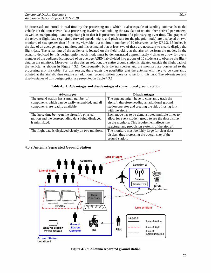
4.3.2 Antenna Separated Ground Station
Figure 4.3.2: Antenna separated ground station
Conceptual Design Document 2014 Aerospace Senior Projects ASEN 4018
26
The second design option involves a ground station composed of a processing unit, 2 monitor displays, the
pilot’s RC controller, and a transceiver. This design differs from the previous concept in that the ground station is
separated into two locations, as shown in Figure 4.3.2. A transceiver linking the aircraft to the ground is placed in
the center of the flight path (Location 2), and it is then constantly linked to the rest of the ground station (Location 1)
via radio waves or cable. Consequently, this design requires two additional transceivers or a fairly long cable. This
design optimizes the downlink and uplink between aircraft and ground, and reduces the possibility of having to track
the aircraft to maintain communication since the range of the link is reduced. The data downlink is composed of the
raw flight data, similarly to the previous design solution, and the data processing consists of manipulating the raw
data to display the relevant parameters in real-time in the form of plots as a function of time. These displays are
made apparent on the monitors (at least 15 inches in size), which are visible to at least 10 observers. The remaining
of the audience is located outside the flight path of the aircraft observing the modes.
The advantages and disadvantages of the second design option are tabulated in Table 4.3.2.
Table 4.3.2: Advantages and disadvantages of antenna separated
Advantages Disadvantages
The aircraft does not have to be tracked with an
antenna since a transceiver is placed in the center if
the flight path.
One additional link is required for communication
between the ground station processing unit and the
aircraft. This increases the risk of loss of link, and
increases the link budget.
The lapse time between the aircraft physical motion
and the data display is kept minimal even if an extra
link is required.
Each mode has to be demonstrated multiple times to
allow for every student group to see the data display
on the monitors. This requirement affects the
structural and propulsion systems of the aircraft.
The flight data is displayed clearly on two monitors. The monitors must be fairly large for clear data
display, thus increasing the overall size of the
ground station, and more components are required
for communication.
It is necessary to supply power to Location 2 in
Figure 4.3.2.
Conceptual Design Document 2014 Aerospace Senior Projects ASEN 4018
27
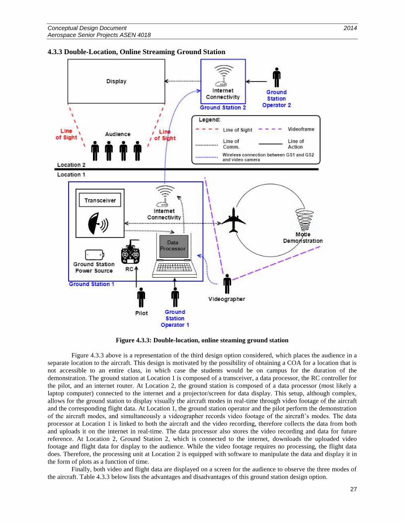
4.3.3 Double-Location, Online Streaming Ground Station
Figure 4.3.3: Double-location, online steaming ground station
Figure 4.3.3 above is a representation of the third design option considered, which places the audience in a
separate location to the aircraft. This design is motivated by the possibility of obtaining a COA for a location that is
not accessible to an entire class, in which case the students would be on campus for the duration of the
demonstration. The ground station at Location 1 is composed of a transceiver, a data processor, the RC controller for
the pilot, and an internet router. At Location 2, the ground station is composed of a data processor (most likely a
laptop computer) connected to the internet and a projector/screen for data display. This setup, although complex,
allows for the ground station to display visually the aircraft modes in real-time through video footage of the aircraft
and the corresponding flight data. At Location 1, the ground station operator and the pilot perform the demonstration
of the aircraft modes, and simultaneously a videographer records video footage of the aircraft’s modes. The data
processor at Location 1 is linked to both the aircraft and the video recording, therefore collects the data from both
and uploads it on the internet in real-time. The data processor also stores the video recording and data for future
reference. At Location 2, Ground Station 2, which is connected to the internet, downloads the uploaded video
footage and flight data for display to the audience. While the video footage requires no processing, the flight data
does. Therefore, the processing unit at Location 2 is equipped with software to manipulate the data and display it in
the form of plots as a function of time.
Finally, both video and flight data are displayed on a screen for the audience to observe the three modes of
the aircraft. Table 4.3.3 below lists the advantages and disadvantages of this ground station design option.
Conceptual Design Document 2014 Aerospace Senior Projects ASEN 4018
28
Table 4.3.3: Advantages and disadvantages of double-location, online streaming ground station
Advantages Disadvantages
Audience does not have to be physically present at
the same location as the pilot during aircraft mode
demonstration.
Increases the number of people operating the
ground station system.
A demonstration of each of the three modes can be
performed just once for the viewing of a large
audience.
Highly dependent on Internet connectivity, thus
reliability of communication is decreased.
Reduces the size and weight of the entire ground
station without large display screens.
Additional costs to purchase an Internet router.
The lapse time is increased and video footage and
flight data might not be synchronized at the display.
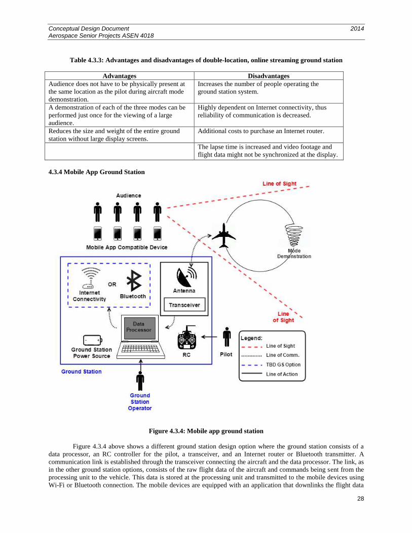
4.3.4 Mobile App Ground Station
Figure 4.3.4: Mobile app ground station
Figure 4.3.4 above shows a different ground station design option where the ground station consists of a
data processor, an RC controller for the pilot, a transceiver, and an Internet router or Bluetooth transmitter. A
communication link is established through the transceiver connecting the aircraft and the data processor. The link, as
in the other ground station options, consists of the raw flight data of the aircraft and commands being sent from the
processing unit to the vehicle. This data is stored at the processing unit and transmitted to the mobile devices using
Wi-Fi or Bluetooth connection. The mobile devices are equipped with an application that downlinks the flight data
Conceptual Design Document 2014 Aerospace Senior Projects ASEN 4018
29
and displays the parameters on a plot as a function of time. Table 4.3.4 below presents the advantages and
disadvantages of this ground station design option.
Table 4.3.4: Advantages and disadvantages of mobile app ground station
Advantages Disadvantages
Improves audience visibility of data; each individual
has a personal view of the data.
Highly dependent on Internet/Bluetooth
connectivity, increased risk of loss of signal.
A demonstration of each of the three modes can be
performed just once for the viewing of a large
audience.
Additional safety measures have to be taken into
consideration with the presence of the audience
during flight operation.
Reduces the size of the entire ground station without
large display screens. Lapse time for data display increases.
Requires that every observer has a mobile device
capable of operating the application.
Flight data display screen is small, making display
less clear and harder to see.
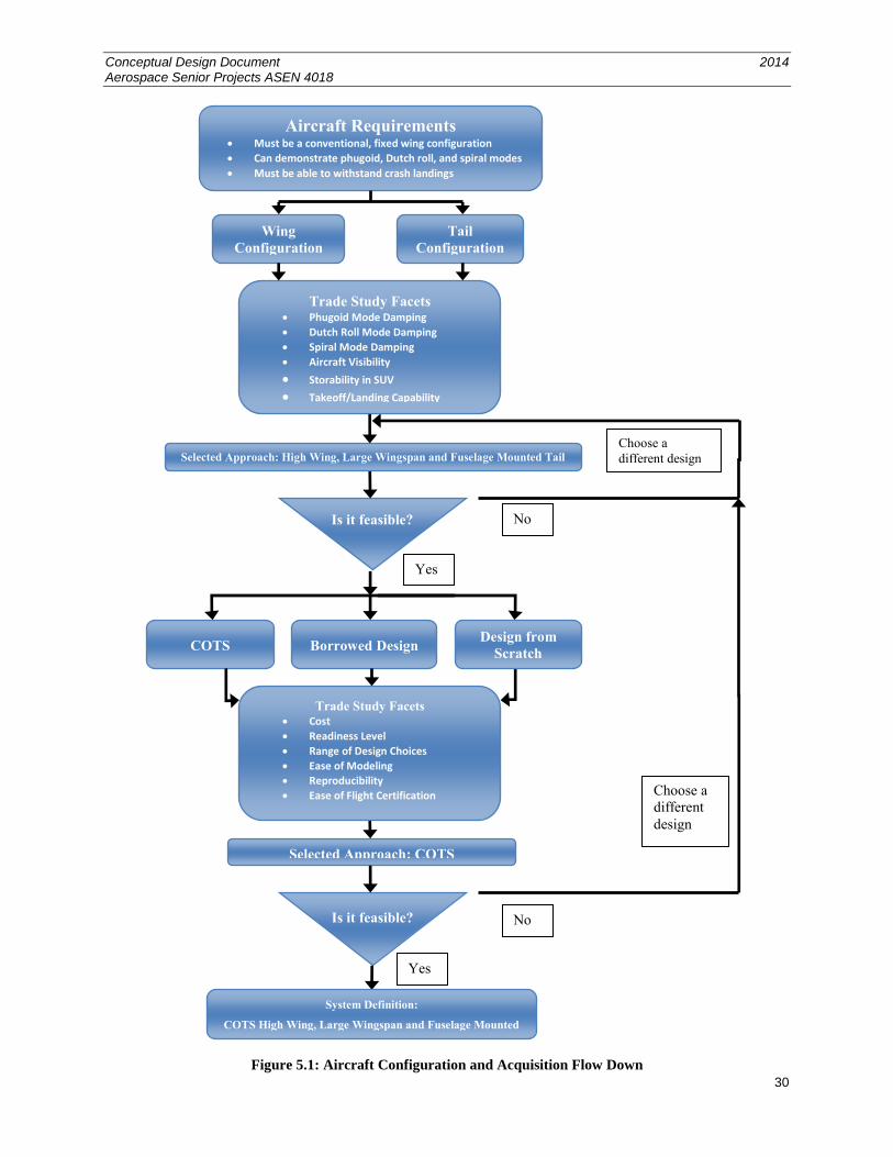
5.0 Trade Study Process and Results
5.1 Aircraft Configuration Trade Study
Figure 5.1 displays the process through which the aircraft configuration trade study was completed. The
diagram flows from the top down and incorporates the locations where feasibility checks were performed.
Conceptual Design Document 2014 Aerospace Senior Projects ASEN 4018
30
Figure 5.1: Aircraft Configuration and Acquisition Flow Down
Choose a
different
design
Aircraft Requirements Must be a conventional, fixed wing configuration
Can demonstrate phugoid, Dutch roll, and spiral modes
Must be able to withstand crash landings
COTS
Selected Approach: COTS
Is it feasible?
Yes
No
Borrowed Design Design from
Scratch
System Definition:
COTS High Wing, Large Wingspan and Fuselage Mounted
Tail
Trade Study Facets Phugoid Mode Damping
Dutch Roll Mode Damping
Spiral Mode Damping
Aircraft Visibility
Storability in SUV Takeoff/Landing Capability
Selected Approach: High Wing, Large Wingspan and Fuselage Mounted Tail
Is it feasible? No
Wing
Configuration
Tail
Configuration
Yes
Choose a
different design
Trade Study Facets Cost
Readiness Level
Range of Design Choices
Ease of Modeling
Reproducibility
Ease of Flight Certification
Conceptual Design Document 2014 Aerospace Senior Projects ASEN 4018
31
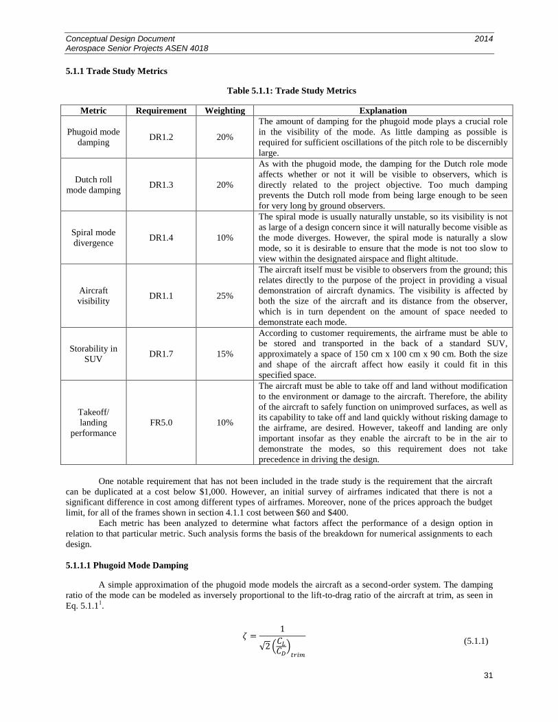
5.1.1 Trade Study Metrics
Table 5.1.1: Trade Study Metrics
Metric Requirement Weighting Explanation
Phugoid mode
damping DR1.2 20%
The amount of damping for the phugoid mode plays a crucial role
in the visibility of the mode. As little damping as possible is
required for sufficient oscillations of the pitch role to be discernibly
large.
Dutch roll
mode damping DR1.3 20%
As with the phugoid mode, the damping for the Dutch role mode
affects whether or not it will be visible to observers, which is
directly related to the project objective. Too much damping
prevents the Dutch roll mode from being large enough to be seen
for very long by ground observers.
Spiral mode
divergence DR1.4 10%
The spiral mode is usually naturally unstable, so its visibility is not
as large of a design concern since it will naturally become visible as
the mode diverges. However, the spiral mode is naturally a slow
mode, so it is desirable to ensure that the mode is not too slow to
view within the designated airspace and flight altitude.
Aircraft
visibility DR1.1 25%
The aircraft itself must be visible to observers from the ground; this
relates directly to the purpose of the project in providing a visual
demonstration of aircraft dynamics. The visibility is affected by
both the size of the aircraft and its distance from the observer,
which is in turn dependent on the amount of space needed to
demonstrate each mode.
Storability in
SUV DR1.7 15%
According to customer requirements, the airframe must be able to
be stored and transported in the back of a standard SUV,
approximately a space of 150 cm x 100 cm x 90 cm. Both the size
and shape of the aircraft affect how easily it could fit in this
specified space.
Takeoff/
landing
performance
FR5.0 10%
The aircraft must be able to take off and land without modification
to the environment or damage to the aircraft. Therefore, the ability
of the aircraft to safely function on unimproved surfaces, as well as
its capability to take off and land quickly without risking damage to
the airframe, are desired. However, takeoff and landing are only
important insofar as they enable the aircraft to be in the air to
demonstrate the modes, so this requirement does not take
precedence in driving the design.
One notable requirement that has not been included in the trade study is the requirement that the aircraft
can be duplicated at a cost below $1,000. However, an initial survey of airframes indicated that there is not a
significant difference in cost among different types of airframes. Moreover, none of the prices approach the budget
limit, for all of the frames shown in section 4.1.1 cost between $60 and $400.
Each metric has been analyzed to determine what factors affect the performance of a design option in
relation to that particular metric. Such analysis forms the basis of the breakdown for numerical assignments to each
design.
5.1.1.1 Phugoid Mode Damping
A simple approximation of the phugoid mode models the aircraft as a second-order system. The damping
ratio of the mode can be modeled as inversely proportional to the lift-to-drag ratio of the aircraft at trim, as seen in
Eq. 5.1.11.
(5.1.1)
Conceptual Design Document 2014 Aerospace Senior Projects ASEN 4018
32
To ensure that the phugoid mode is visible for a significant period of time, the damping ratio must be as
low as possible, so it is optimal to increase the lift-to-drag ratio. It is desirable for the aircraft to possess traits that
increase the lift—such as large wings with no sweep or dihedral—and traits that decrease the drag—such as a large
aspect ratio.
As the aircraft has a small change in angle of attack during the phugoid mode, the size of the horizontal
stabilizer does little to affect the mode. For the tail trade study, stabilizer size will not be considered. For this trade,
the size of the empennage surfaces will be considered for their effect on drag. A larger surface will have more drag
effects, which will subsequently increase the damping of the phugoid mode.
Numbers for the trade study are assigned based on what traits an aircraft possesses:
Wing Traits
1. Traits that produce both low lift and high drag
2. Traits that produce either low lift or high drag
3. Traits that do not significantly increase or decrease or decrease lift or drag, or else affect lift and drag in
ways that balance each other
4. Traits that produce either high lift or low drag
5. Traits that produce both high lift and low drag
Empennage Traits
1. Large surface area plus extra drag effects
2. Large surface area
3. Medium surface area
4. Small surface area
5. Small surface area plus low drag effects
5.1.1.2 Dutch Roll Mode Damping
The Dutch roll mode can also be modeled with a simple second order system using lateral stability
derivatives, as given in Eq. 5.1.21.
(5.1.2)
The terms are eigenvalues, is the forward speed, and the rest of the variables are functions of stability
derivatives. Solving this system and neglecting smaller terms gives the eigenvalue approximations seen in Eq. 5.1.3.
This equation indicates that the real part of the eigenvalue, which determines the damping of the system, depends on
the stability terms v and r. These terms approximately correspond to side force due to sideslip and yaw moment
due to yaw rate.
(5.1.3)
Equation 5.1.3 provides some insight into the effects on the Dutch roll mode, such as how wing sweep,
which tends to decrease the magnitude of yaw damping, moves the real part of the eigenvalue closer to zero, thus
decreasing the damping on the mode. However, many other effects are not readily obvious from this simplified
equation.
Further research indicates that aircraft with traits that increase the (restoring) roll moment have a large
Dutch roll mode12
. Three primary characteristics include placing the wings above the center of mass, sweeping the
wings, and giving the wings a positive dihedral angle12
. These three traits, commonly associated with the dihedral
affect, indicate that a larger dihedral effect increases Dutch roll tendencies. As such, the traits that contribute to the
dihedral effect are used to assign numbers for this metric. Emphasis is placed on the dihedral angle because it is the
most significant contribution to the dihedral effect.
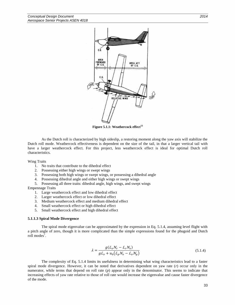
Another significant effect on the Dutch roll mode is due to the weathercock effect9. This effect occurs when
the aircraft has a nonzero sideslip angle, causing the vertical fin to apply a restoring moment on the aircraft.
Conceptual Design Document 2014 Aerospace Senior Projects ASEN 4018
33
Figure 5.1.1: Weathercock effect13
As the Dutch roll is characterized by high sideslip, a restoring moment along the yaw axis will stabilize the
Dutch roll mode. Weathercock effectiveness is dependent on the size of the tail, in that a larger vertical tail with
have a larger weathercock effect. For this project, less weathercock effect is ideal for optimal Dutch roll
characteristics.
Wing Traits
1. No traits that contribute to the dihedral effect
2. Possessing either high wings or swept wings
3. Possessing both high wings or swept wings, or possessing a dihedral angle
4. Possessing dihedral angle and either high wings or swept wings
5. Possessing all three traits: dihedral angle, high wings, and swept wings
Empennage Traits
1. Large weathercock effect and low dihedral effect
2. Larger weathercock effect or low dihedral effect
3. Medium weathercock effect and medium dihedral effect
4. Small weathercock effect or high dihedral effect
5. Small weathercock effect and high dihedral effect
5.1.1.3 Spiral Mode Divergence
The spiral mode eigenvalue can be approximated by the expression in Eq. 5.1.4, assuming level flight with
a pitch angle of zero, though it is more complicated than the simple expressions found for the phugoid and Dutch
roll modes1.
(5.1.4)
The complexity of Eq. 5.1.4 limits its usefulness in determining what wing characteristics lead to a faster
spiral mode divergence. However, it can be noted that derivatives dependent on yaw rate (r) occur only in the
numerator, while terms that depend on roll rate (p) appear only in the denominator. This seems to indicate that
increasing effects of yaw rate relative to those of roll rate would increase the eigenvalue and cause faster divergence
of the mode.
Conceptual Design Document 2014 Aerospace Senior Projects ASEN 4018
34
One such instance is in the term r, which indicates the roll moment due to yaw rate. The non-dimensional
derivative is proportional to the lift coefficient1, so a larger lift coefficient increases the magnitude of this term.
Likewise, the other term dependent on yaw rate, the yaw damping r, has already been noted to decrease in
magnitude with wing sweep. This indicates that while wing sweep may lead to less Dutch roll damping, it also slows
the spiral mode divergence. Numerical values are assigned based on these effects of lift coefficient and wing sweep.
Although the term v appears in the numerator and denominator of Equation 5.1.4, this term tends to increase the
spiral eigenvalue, thus decreasing its stability9. This term represents the weathercock effect, which is dependent on
tail size. A larger tail will have a larger weathercock effect, thus decreasing the stability of the spiral mode.
Recovery from the spiral mode is also an important factor for this project. Multiple tail surfaces can assist with
spiral recovery when the tail surfaces experience low air flow near stall conditions.
Wing Traits
1. Low lift coefficient, wing sweep, and a small tail
2. Low lift coefficient or wing sweep
3. Average lift coefficient, no wing sweep
4. High lift coefficient or forward wing sweep
5. High lift coefficient, forward wing sweep, and a large tail
Empennage Traits
1. High dihedral effect and small weathercock effect
2. High dihedral effect or small weathercock effect
3. Some dihedral effect and some weathercock effect
4. Low dihedral effect and large weathercock effect
5. Low dihedral effect, large weathercock effect and spiral recovery
5.1.1.4 Aircraft Visibility
The visibility of the aircraft is a metric of great importance, for the aircraft must be visible to ground
observers for a successful demonstration of the aircraft modes. The size of the wings understandably affects
visibility; larger wings make the aircraft more visible. However, the amount of space needed to demonstrate each
mode also determines how far away the aircraft will be from the observer, which directly affects the visibility of the
aircraft.
The second-order approximation of the phugoid mode models the period of the mode to be proportional to
the trim speed uo of the aircraft, as seen in Eq. 5.1.51. Since the distance covered by the aircraft for a single period is
proportional to both flight speed and period, the distance required for one period of the phugoid mode is
proportional to the square of the trim speed, as seen in Eq. 5.1.6.
(5.1.5)
(5.1.6)
The period of the Dutch roll mode has less dependence on speed, as seen from the imaginary term of Eq.
5.1.6. In fact, substituting for the term v eliminates forward speed from the expression for the distance needed for
a single Dutch roll oscillation, since the dimensional term v is proportional to the trim speed, as seen in Eq. 5.1.7
and Eq. 5.1.8.
(5.1.7)
(5.1.8)
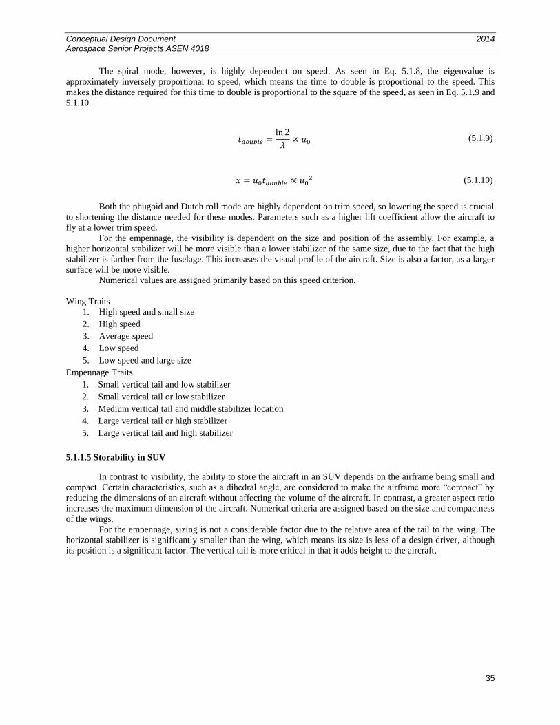
Conceptual Design Document 2014 Aerospace Senior Projects ASEN 4018
35
The spiral mode, however, is highly dependent on speed. As seen in Eq. 5.1.8, the eigenvalue is
approximately inversely proportional to speed, which means the time to double is proportional to the speed. This
makes the distance required for this time to double is proportional to the square of the speed, as seen in Eq. 5.1.9 and
5.1.10.
(5.1.9)
(5.1.10)
Both the phugoid and Dutch roll mode are highly dependent on trim speed, so lowering the speed is crucial
to shortening the distance needed for these modes. Parameters such as a higher lift coefficient allow the aircraft to
fly at a lower trim speed.
For the empennage, the visibility is dependent on the size and position of the assembly. For example, a
higher horizontal stabilizer will be more visible than a lower stabilizer of the same size, due to the fact that the high
stabilizer is farther from the fuselage. This increases the visual profile of the aircraft. Size is also a factor, as a larger
surface will be more visible.
Numerical values are assigned primarily based on this speed criterion.
Wing Traits
1. High speed and small size
2. High speed
3. Average speed
4. Low speed
5. Low speed and large size
Empennage Traits
1. Small vertical tail and low stabilizer
2. Small vertical tail or low stabilizer
3. Medium vertical tail and middle stabilizer location
4. Large vertical tail or high stabilizer
5. Large vertical tail and high stabilizer
5.1.1.5 Storability in SUV
In contrast to visibility, the ability to store the aircraft in an SUV depends on the airframe being small and
compact. Certain characteristics, such as a dihedral angle, are considered to make the airframe more “compact” by
reducing the dimensions of an aircraft without affecting the volume of the aircraft. In contrast, a greater aspect ratio
increases the maximum dimension of the aircraft. Numerical criteria are assigned based on the size and compactness
of the wings.
For the empennage, sizing is not a considerable factor due to the relative area of the tail to the wing. The
horizontal stabilizer is significantly smaller than the wing, which means its size is less of a design driver, although
its position is a significant factor. The vertical tail is more critical in that it adds height to the aircraft.
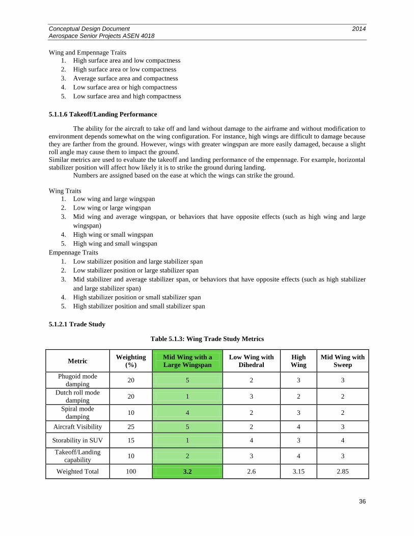
Conceptual Design Document 2014 Aerospace Senior Projects ASEN 4018
36
Wing and Empennage Traits
1. High surface area and low compactness
2. High surface area or low compactness
3. Average surface area and compactness
4. Low surface area or high compactness
5. Low surface area and high compactness
5.1.1.6 Takeoff/Landing Performance
The ability for the aircraft to take off and land without damage to the airframe and without modification to
environment depends somewhat on the wing configuration. For instance, high wings are difficult to damage because
they are farther from the ground. However, wings with greater wingspan are more easily damaged, because a slight
roll angle may cause them to impact the ground.
Similar metrics are used to evaluate the takeoff and landing performance of the empennage. For example, horizontal
stabilizer position will affect how likely it is to strike the ground during landing.
Numbers are assigned based on the ease at which the wings can strike the ground.
Wing Traits
1. Low wing and large wingspan
2. Low wing or large wingspan
3. Mid wing and average wingspan, or behaviors that have opposite effects (such as high wing and large
wingspan)
4. High wing or small wingspan
5. High wing and small wingspan
Empennage Traits
1. Low stabilizer position and large stabilizer span
2. Low stabilizer position or large stabilizer span
3. Mid stabilizer and average stabilizer span, or behaviors that have opposite effects (such as high stabilizer
and large stabilizer span)
4. High stabilizer position or small stabilizer span
5. High stabilizer position and small stabilizer span
5.1.2.1 Trade Study
Table 5.1.3: Wing Trade Study Metrics
Metric Weighting
(%)
Mid Wing with a
Large Wingspan
Low Wing with
Dihedral
High
Wing
Mid Wing with
Sweep
Phugoid mode
damping 20 5 2 3 3
Dutch roll mode
damping 20 1 3 2 2
Spiral mode
damping 10 4 2 3 2
Aircraft Visibility 25 5 2 4 3
Storability in SUV 15 1 4 3 4
Takeoff/Landing
capability 10 2 3 4 3
Weighted Total 100 3.2 2.6 3.15 2.85
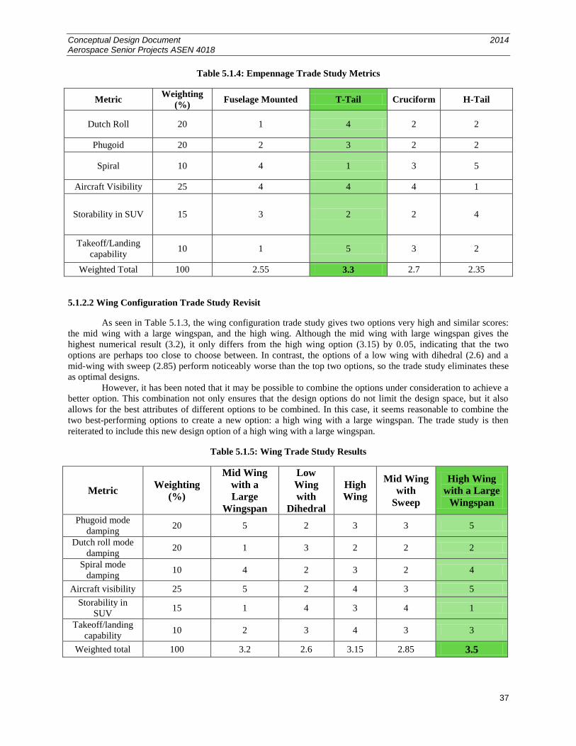
Conceptual Design Document 2014 Aerospace Senior Projects ASEN 4018
37
Table 5.1.4: Empennage Trade Study Metrics
Metric Weighting
(%) Fuselage Mounted T-Tail Cruciform H-Tail
Dutch Roll 20 1 4 2 2
Phugoid 20 2 3 2 2
Spiral 10 4 1 3 5
Aircraft Visibility 25 4 4 4 1
Storability in SUV 15 3 2 2 4
Takeoff/Landing
capability 10 1 5 3 2
Weighted Total 100 2.55 3.3 2.7 2.35
5.1.2.2 Wing Configuration Trade Study Revisit
As seen in Table 5.1.3, the wing configuration trade study gives two options very high and similar scores:
the mid wing with a large wingspan, and the high wing. Although the mid wing with large wingspan gives the
highest numerical result (3.2), it only differs from the high wing option (3.15) by 0.05, indicating that the two
options are perhaps too close to choose between. In contrast, the options of a low wing with dihedral (2.6) and a
mid-wing with sweep (2.85) perform noticeably worse than the top two options, so the trade study eliminates these
as optimal designs.
However, it has been noted that it may be possible to combine the options under consideration to achieve a
better option. This combination not only ensures that the design options do not limit the design space, but it also
allows for the best attributes of different options to be combined. In this case, it seems reasonable to combine the
two best-performing options to create a new option: a high wing with a large wingspan. The trade study is then
reiterated to include this new design option of a high wing with a large wingspan.
Table 5.1.5: Wing Trade Study Results
Metric Weighting
(%)
Mid Wing
with a
Large
Wingspan
Low
Wing
with
Dihedral
High
Wing
Mid Wing
with
Sweep
High Wing
with a Large
Wingspan
Phugoid mode
damping 20 5 2 3 3 5
Dutch roll mode
damping 20 1 3 2 2 2
Spiral mode
damping 10 4 2 3 2 4
Aircraft visibility 25 5 2 4 3 5
Storability in
SUV 15 1 4 3 4 1
Takeoff/landing
capability 10 2 3 4 3 3
Weighted total 100 3.2 2.6 3.15 2.85 3.5
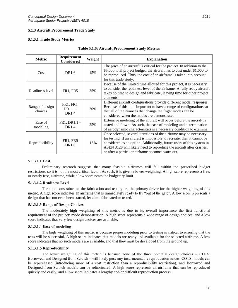
Conceptual Design Document 2014 Aerospace Senior Projects ASEN 4018
38
5.1.3 Aircraft Procurement Trade Study
5.1.3.1 Trade Study Metrics
Table 5.1.6: Aircraft Procurement Study Metrics
Metric Requirement
Considered Weight Explanation
Cost DR1.6 15%
The price of an aircraft is critical for the project. In addition to the
$5,000 total project budget, the aircraft has to cost under $1,000 to
be reproduced. Thus, the cost of an airframe is taken into account
for this trade study.
Readiness level FR1, FR5 25%
Because of the limited time allotted for this project, it is necessary
to consider the readiness level of the airframe. A fully ready aircraft
takes no time to design and fabricate, leaving time for other project
elements.
Range of design
choices
FR1, FR5,
DR1.1 –
DR1.4
20%
Different aircraft configurations provide different modal responses.
Because of this, it is important to have a range of configurations so
that all of the nuances that change the flight modes can be
considered when the modes are demonstrated.
Ease of
modeling
FR1, DR1.1 –
DR1.4 25%
Extensive modeling of the aircraft will occur before the aircraft is
tested and flown. As such, the ease of modeling and determination
of aerodynamic characteristics is a necessary condition to examine.
Reproducibility FR1, FR5
DR1.6 15%
Once selected, several iterations of the airframe may be necessary
for testing. If an aircraft is impossible to recreate, then it cannot be
considered as an option. Additionally, future users of this system in
ASEN 3128 will likely need to reproduce the aircraft after crashes,
or after a particular airframe becomes worn out.
5.1.3.1.1 Cost
Preliminary research suggests that many feasible airframes will fall within the prescribed budget
restrictions, so it is not the most critical factor. As such, it is given a lower weighting. A high score represents a free,
or nearly free, airframe, while a low score nears the budgetary limit.
5.1.3.1.2 Readiness Level
The time constraints on the fabrication and testing are the primary driver for the higher weighting of this
metric. A high score indicates an airframe that is immediately ready to fly “out of the gate”. A low score represents a
design that has not even been started, let alone fabricated or tested.
5.1.3.1.3 Range of Design Choices
The moderately high weighting of this metric is due to its overall importance the first functional
requirement of the project: mode demonstration. A high score represents a wide range of design choices, and a low
score indicates that very few design choices are available.
5.1.3.1.4 Ease of modeling
The high weighting of this metric is because proper modeling prior to testing is critical to ensuring that the
tests will be successful. A high score indicates that models are ready and available for the selected airframe. A low
score indicates that no such models are available, and that they must be developed from the ground up.
5.1.3.1.5 Reproducibility
The lower weighting of this metric is because none of the three potential design choices – COTS,
Borrowed, and Designed from Scratch – will likely pose any insurmountable reproduction issues. COTS models can
be repurchased (introducing more of a cost restriction than a reproducibility restriction), and Borrowed and
Designed from Scratch models can be refabricated. A high score represents an airframe that can be reproduced
quickly and easily, and a low score indicates a lengthy and/or difficult reproduction process.
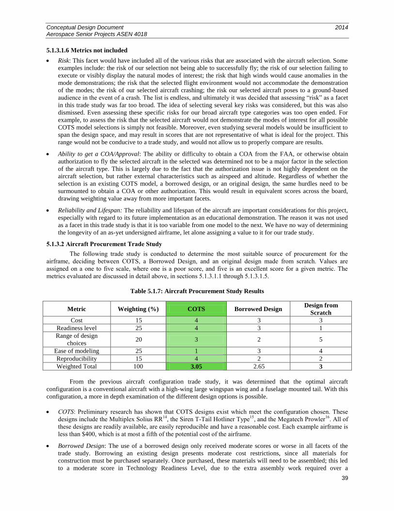
Conceptual Design Document 2014 Aerospace Senior Projects ASEN 4018
39
5.1.3.1.6 Metrics not included
Risk: This facet would have included all of the various risks that are associated with the aircraft selection. Some
examples include: the risk of our selection not being able to successfully fly; the risk of our selection failing to
execute or visibly display the natural modes of interest; the risk that high winds would cause anomalies in the
mode demonstrations; the risk that the selected flight environment would not accommodate the demonstration
of the modes; the risk of our selected aircraft crashing; the risk our selected aircraft poses to a ground-based
audience in the event of a crash. The list is endless, and ultimately it was decided that assessing “risk” as a facet
in this trade study was far too broad. The idea of selecting several key risks was considered, but this was also
dismissed. Even assessing these specific risks for our broad aircraft type categories was too open ended. For
example, to assess the risk that the selected aircraft would not demonstrate the modes of interest for all possible
COTS model selections is simply not feasible. Moreover, even studying several models would be insufficient to
span the design space, and may result in scores that are not representative of what is ideal for the project. This
range would not be conducive to a trade study, and would not allow us to properly compare are results.
Ability to get a COA/Approval: The ability or difficulty to obtain a COA from the FAA, or otherwise obtain
authorization to fly the selected aircraft in the selected was determined not to be a major factor in the selection
of the aircraft type. This is largely due to the fact that the authorization issue is not highly dependent on the
aircraft selection, but rather external characteristics such as airspeed and altitude. Regardless of whether the
selection is an existing COTS model, a borrowed design, or an original design, the same hurdles need to be
surmounted to obtain a COA or other authorization. This would result in equivalent scores across the board,
drawing weighting value away from more important facets.
Reliability and Lifespan: The reliability and lifespan of the aircraft are important considerations for this project,
especially with regard to its future implementation as an educational demonstration. The reason it was not used
as a facet in this trade study is that it is too variable from one model to the next. We have no way of determining
the longevity of an as-yet undersigned airframe, let alone assigning a value to it for our trade study.
5.1.3.2 Aircraft Procurement Trade Study
The following trade study is conducted to determine the most suitable source of procurement for the
airframe, deciding between COTS, a Borrowed Design, and an original design made from scratch. Values are
assigned on a one to five scale, where one is a poor score, and five is an excellent score for a given metric. The
metrics evaluated are discussed in detail above, in sections 5.1.3.1.1 through 5.1.3.1.5.
Table 5.1.7: Aircraft Procurement Study Results
Metric Weighting (%) COTS Borrowed Design Design from
Scratch
Cost 15 4 3 3
Readiness level 25 4 3 1
Range of design
choices 20 3 2 5
Ease of modeling 25 1 3 4
Reproducibility 15 4 2 2
Weighted Total 100 3.05 2.65 3
From the previous aircraft configuration trade study, it was determined that the optimal aircraft
configuration is a conventional aircraft with a high-wing large wingspan wing and a fuselage mounted tail. With this
configuration, a more in depth examination of the different design options is possible.
COTS: Preliminary research has shown that COTS designs exist which meet the configuration chosen. These
designs include the Multiplex Solius RR14
, the Siren T-Tail Hotliner Type15
, and the Megatech Prowler16
. All of
these designs are readily available, are easily reproducible and have a reasonable cost. Each example airframe is
less than $400, which is at most a fifth of the potential cost of the airframe.
Borrowed Design: The use of a borrowed design only received moderate scores or worse in all facets of the
trade study. Borrowing an existing design presents moderate cost restrictions, since all materials for
construction must be purchased separately. Once purchased, these materials will need to be assembled; this led
to a moderate score in Technology Readiness Level, due to the extra assembly work required over a
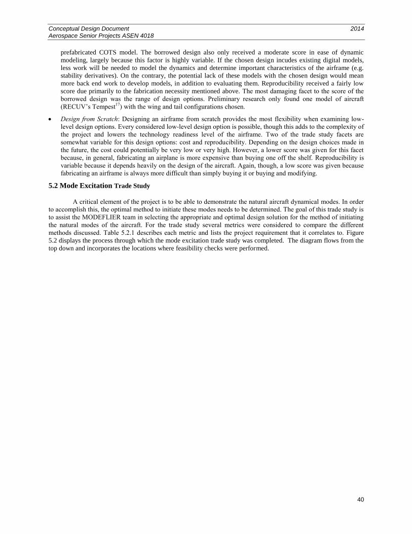
Conceptual Design Document 2014 Aerospace Senior Projects ASEN 4018
40
prefabricated COTS model. The borrowed design also only received a moderate score in ease of dynamic
modeling, largely because this factor is highly variable. If the chosen design incudes existing digital models,
less work will be needed to model the dynamics and determine important characteristics of the airframe (e.g.
stability derivatives). On the contrary, the potential lack of these models with the chosen design would mean
more back end work to develop models, in addition to evaluating them. Reproducibility received a fairly low
score due primarily to the fabrication necessity mentioned above. The most damaging facet to the score of the
borrowed design was the range of design options. Preliminary research only found one model of aircraft
(RECUV’s Tempest17
) with the wing and tail configurations chosen.
Design from Scratch: Designing an airframe from scratch provides the most flexibility when examining low-
level design options. Every considered low-level design option is possible, though this adds to the complexity of
the project and lowers the technology readiness level of the airframe. Two of the trade study facets are
somewhat variable for this design options: cost and reproducibility. Depending on the design choices made in
the future, the cost could potentially be very low or very high. However, a lower score was given for this facet
because, in general, fabricating an airplane is more expensive than buying one off the shelf. Reproducibility is
variable because it depends heavily on the design of the aircraft. Again, though, a low score was given because
fabricating an airframe is always more difficult than simply buying it or buying and modifying.
5.2 Mode Excitation Trade Study
A critical element of the project is to be able to demonstrate the natural aircraft dynamical modes. In order
to accomplish this, the optimal method to initiate these modes needs to be determined. The goal of this trade study is
to assist the MODEFLIER team in selecting the appropriate and optimal design solution for the method of initiating
the natural modes of the aircraft. For the trade study several metrics were considered to compare the different
methods discussed. Table 5.2.1 describes each metric and lists the project requirement that it correlates to. Figure
5.2 displays the process through which the mode excitation trade study was completed. The diagram flows from the
top down and incorporates the locations where feasibility checks were performed.
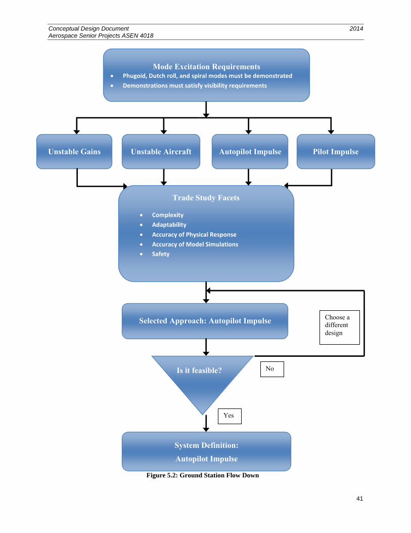
Conceptual Design Document 2014 Aerospace Senior Projects ASEN 4018
41
Figure 5.2: Ground Station Flow Down
Mode Excitation Requirements Phugoid, Dutch roll, and spiral modes must be demonstrated
Demonstrations must satisfy visibility requirements
Unstable Gains Unstable Aircraft Autopilot Impulse
Trade Study Facets
Complexity
Adaptability
Accuracy of Physical Response
Accuracy of Model Simulations
Safety
Selected Approach: Autopilot Impulse
Is it feasible?
Is it feasible?
System Definition:
Autopilot Impulse
Yes
No
Choose a
different
design
Pilot Impulse
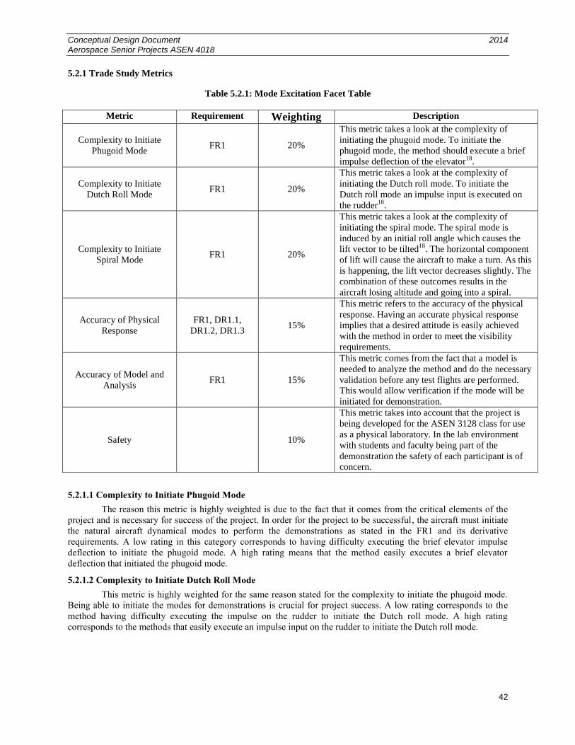
Conceptual Design Document 2014 Aerospace Senior Projects ASEN 4018
42
5.2.1 Trade Study Metrics
Table 5.2.1: Mode Excitation Facet Table
Metric Requirement Weighting Description
Complexity to Initiate
Phugoid Mode FR1 20%
This metric takes a look at the complexity of
initiating the phugoid mode. To initiate the
phugoid mode, the method should execute a brief
impulse deflection of the elevator18
.
Complexity to Initiate
Dutch Roll Mode FR1 20%
This metric takes a look at the complexity of
initiating the Dutch roll mode. To initiate the
Dutch roll mode an impulse input is executed on
the rudder18
.
Complexity to Initiate
Spiral Mode FR1 20%
This metric takes a look at the complexity of
initiating the spiral mode. The spiral mode is
induced by an initial roll angle which causes the
lift vector to be tilted18
. The horizontal component
of lift will cause the aircraft to make a turn. As this
is happening, the lift vector decreases slightly. The
combination of these outcomes results in the
aircraft losing altitude and going into a spiral.
Accuracy of Physical
Response
FR1, DR1.1,
DR1.2, DR1.3 15%
This metric refers to the accuracy of the physical
response. Having an accurate physical response
implies that a desired attitude is easily achieved
with the method in order to meet the visibility
requirements.
Accuracy of Model and
Analysis FR1 15%
This metric comes from the fact that a model is
needed to analyze the method and do the necessary
validation before any test flights are performed.
This would allow verification if the mode will be
initiated for demonstration.
Safety 10%
This metric takes into account that the project is
being developed for the ASEN 3128 class for use
as a physical laboratory. In the lab environment
with students and faculty being part of the
demonstration the safety of each participant is of
concern.
5.2.1.1 Complexity to Initiate Phugoid Mode
The reason this metric is highly weighted is due to the fact that it comes from the critical elements of the
project and is necessary for success of the project. In order for the project to be successful, the aircraft must initiate
the natural aircraft dynamical modes to perform the demonstrations as stated in the FR1 and its derivative
requirements. A low rating in this category corresponds to having difficulty executing the brief elevator impulse
deflection to initiate the phugoid mode. A high rating means that the method easily executes a brief elevator
deflection that initiated the phugoid mode.
5.2.1.2 Complexity to Initiate Dutch Roll Mode
This metric is highly weighted for the same reason stated for the complexity to initiate the phugoid mode.
Being able to initiate the modes for demonstrations is crucial for project success. A low rating corresponds to the
method having difficulty executing the impulse on the rudder to initiate the Dutch roll mode. A high rating
corresponds to the methods that easily execute an impulse input on the rudder to initiate the Dutch roll mode.
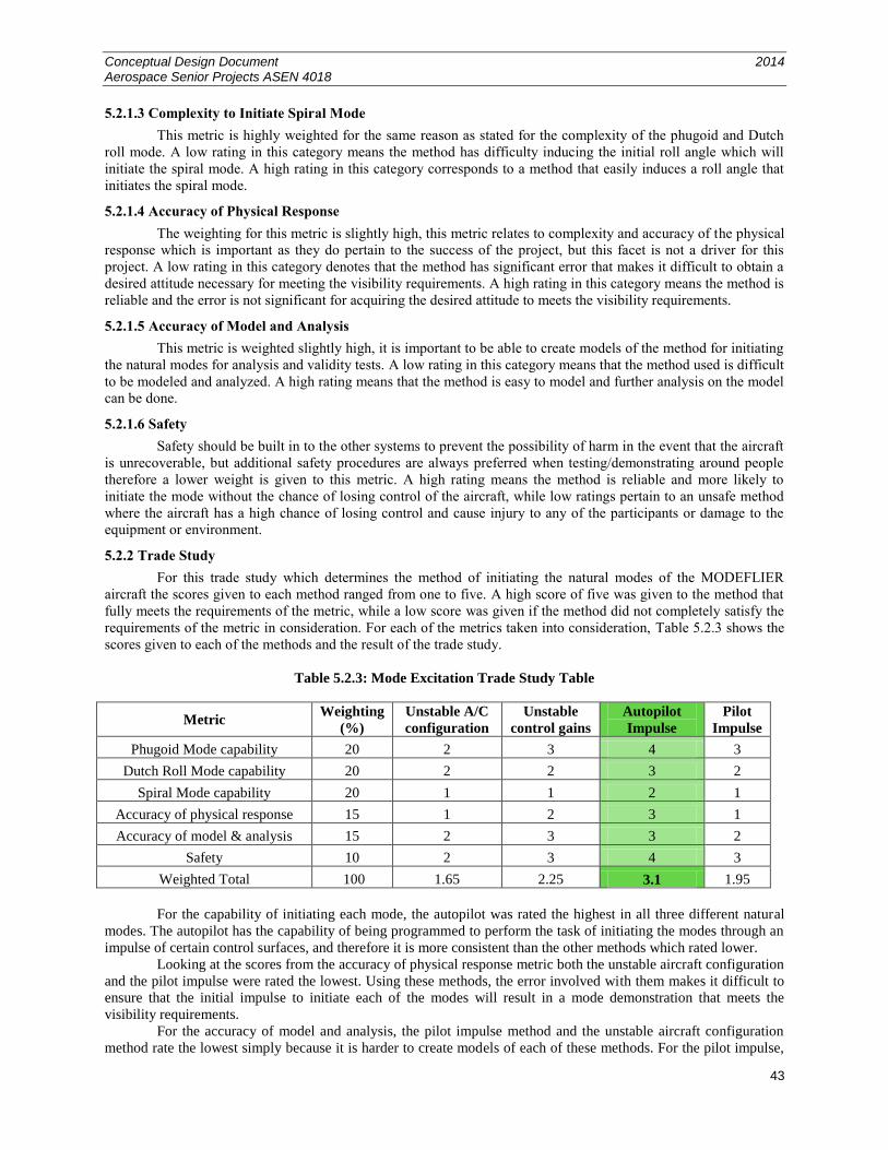
Conceptual Design Document 2014 Aerospace Senior Projects ASEN 4018
43
5.2.1.3 Complexity to Initiate Spiral Mode
This metric is highly weighted for the same reason as stated for the complexity of the phugoid and Dutch
roll mode. A low rating in this category means the method has difficulty inducing the initial roll angle which will
initiate the spiral mode. A high rating in this category corresponds to a method that easily induces a roll angle that
initiates the spiral mode.
5.2.1.4 Accuracy of Physical Response
The weighting for this metric is slightly high, this metric relates to complexity and accuracy of the physical
response which is important as they do pertain to the success of the project, but this facet is not a driver for this
project. A low rating in this category denotes that the method has significant error that makes it difficult to obtain a
desired attitude necessary for meeting the visibility requirements. A high rating in this category means the method is
reliable and the error is not significant for acquiring the desired attitude to meets the visibility requirements.
5.2.1.5 Accuracy of Model and Analysis
This metric is weighted slightly high, it is important to be able to create models of the method for initiating
the natural modes for analysis and validity tests. A low rating in this category means that the method used is difficult
to be modeled and analyzed. A high rating means that the method is easy to model and further analysis on the model
can be done.
5.2.1.6 Safety
Safety should be built in to the other systems to prevent the possibility of harm in the event that the aircraft
is unrecoverable, but additional safety procedures are always preferred when testing/demonstrating around people
therefore a lower weight is given to this metric. A high rating means the method is reliable and more likely to
initiate the mode without the chance of losing control of the aircraft, while low ratings pertain to an unsafe method
where the aircraft has a high chance of losing control and cause injury to any of the participants or damage to the
equipment or environment.
5.2.2 Trade Study
For this trade study which determines the method of initiating the natural modes of the MODEFLIER
aircraft the scores given to each method ranged from one to five. A high score of five was given to the method that
fully meets the requirements of the metric, while a low score was given if the method did not completely satisfy the
requirements of the metric in consideration. For each of the metrics taken into consideration, Table 5.2.3 shows the
scores given to each of the methods and the result of the trade study.
Table 5.2.3: Mode Excitation Trade Study Table
Metric Weighting
(%)
Unstable A/C
configuration
Unstable
control gains
Autopilot
Impulse
Pilot
Impulse
Phugoid Mode capability 20 2 3 4 3
Dutch Roll Mode capability 20 2 2 3 2
Spiral Mode capability 20 1 1 2 1
Accuracy of physical response 15 1 2 3 1
Accuracy of model & analysis 15 2 3 3 2
Safety 10 2 3 4 3
Weighted Total 100 1.65 2.25 3.1 1.95
For the capability of initiating each mode, the autopilot was rated the highest in all three different natural
modes. The autopilot has the capability of being programmed to perform the task of initiating the modes through an
impulse of certain control surfaces, and therefore it is more consistent than the other methods which rated lower.
Looking at the scores from the accuracy of physical response metric both the unstable aircraft configuration
and the pilot impulse were rated the lowest. Using these methods, the error involved with them makes it difficult to
ensure that the initial impulse to initiate each of the modes will result in a mode demonstration that meets the
visibility requirements.
For the accuracy of model and analysis, the pilot impulse method and the unstable aircraft configuration
method rate the lowest simply because it is harder to create models of each of these methods. For the pilot impulse,
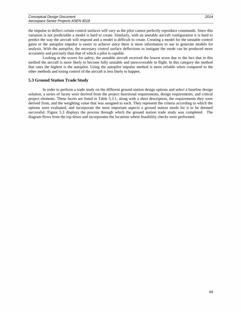
Conceptual Design Document 2014 Aerospace Senior Projects ASEN 4018
44
the impulse to deflect certain control surfaces will vary as the pilot cannot perfectly reproduce commands. Since this
variation is not predictable a model is hard to create. Similarly, with an unstable aircraft configuration it is hard to
predict the way the aircraft will respond and a model is difficult to create. Creating a model for the unstable control
gains or the autopilot impulse is easier to achieve since there is more information to use to generate models for
analysis. With the autopilot, the necessary control surface deflections to instigate the mode can be produced more
accurately and precisely than that of which a pilot is capable.
Looking at the scores for safety, the unstable aircraft received the lowest score due to the fact that in this
method the aircraft is more likely to become fully unstable and unrecoverable in flight. In this category the method
that rates the highest is the autopilot. Using the autopilot impulse method is more reliable when compared to the
other methods and losing control of the aircraft is less likely to happen.
5.3 Ground Station Trade Study
In order to perform a trade study on the different ground station design options and select a baseline design
solution, a series of facets were derived from the project functional requirements, design requirements, and critical
project elements. These facets are listed in Table 5.3.1, along with a short description, the requirements they were
derived from, and the weighting value that was assigned to each. They represent the criteria according to which the
options were evaluated, and incorporate the most important aspects a ground station needs for it to be deemed
successful. Figure 5.3 displays the process through which the ground station trade study was completed. The
diagram flows from the top down and incorporates the locations where feasibility checks were performed.
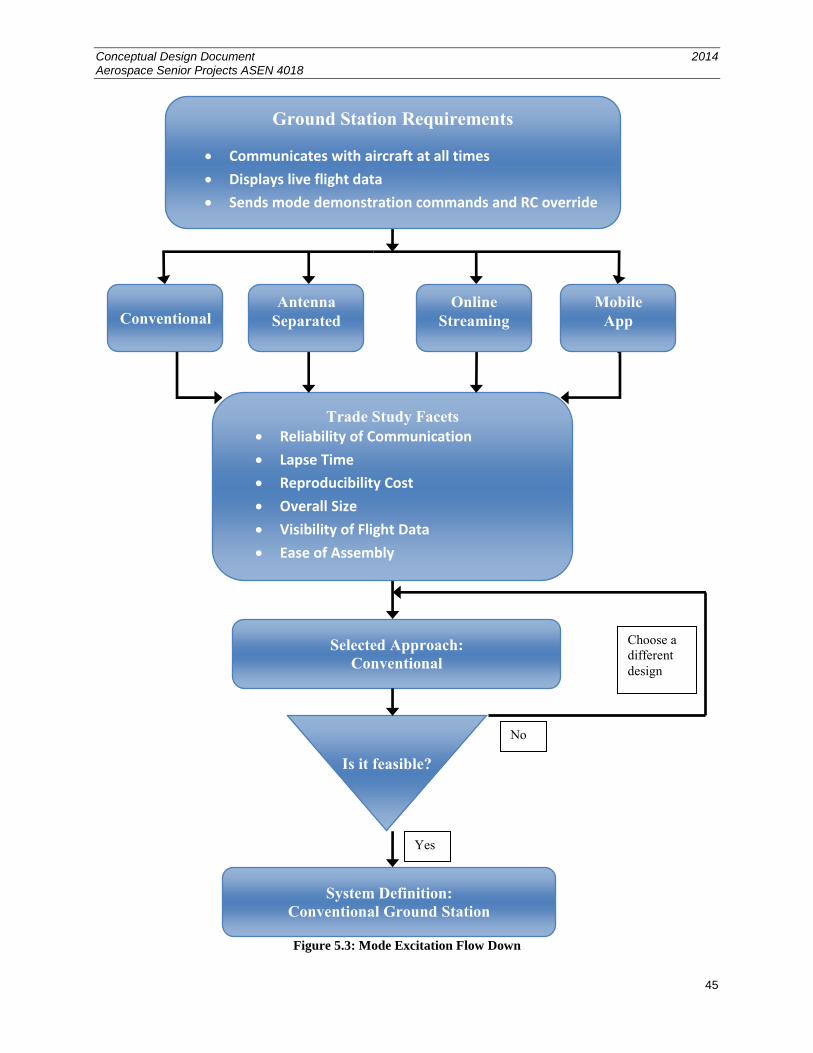
Conceptual Design Document 2014 Aerospace Senior Projects ASEN 4018
45
Figure 5.3: Mode Excitation Flow Down
Conventional
Trade Study Facets
Reliability of Communication
Lapse Time
Reproducibility Cost
Overall Size
Visibility of Flight Data
Ease of Assembly
Selected Approach:
Conventional
Is it feasible?
System Definition:
Conventional Ground Station
Yes
No
Choose a
different
design
Antenna
Separated
Online
Streaming
Mobile
App
Ground Station Requirements
Communicates with aircraft at all times
Displays live flight data
Sends mode demonstration commands and RC override
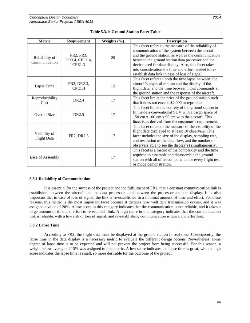
Conceptual Design Document 2014 Aerospace Senior Projects ASEN 4018
46
Table 5.3.1: Ground Station Facet Table
Metric Requirement Weights (%) Description
Reliability of
Communication
FR2, FR3,
DR3.4, CPE1.4,
CPE1.3
20
This facet refers to the measure of the reliability of
communication of the system between the aircraft
and the ground station, as well as the communication
between the ground station data processor and the
device used for data display. Also, this facet takes
into consideration the time and effort needed to re-
establish data link in case of loss of signal.
Lapse Time FR2, DR2.3,
CPE1.4 15
This facet refers to both the time lapse between: the
aircraft’s physical motion and the display of the
flight data, and the time between input commands at
the ground station and the response of the aircraft.
Reproducibility
Cost DR2.4 17
This facet limits the price of the ground station such
that it does not exceed $2,000 to reproduce
Overall Size DR2.5 17
This facet limits the entirety of the ground station to
fit inside a conventional SUV with a cargo space of
150 cm x 100 cm x 90 cm with the aircraft. This
facet is as derived from the customer’s requirement.
Visibility of
Flight Data FR2, DR2.3 17
This facet refers to the measure of the visibility of the
flight data displayed to at least 10 observers. This
facet includes the size of the display, sampling rate,
and resolution of the data flow, and the number of
observers able to see the display(s) simultaneously.
Ease of Assembly 17
This facet is a metric of the complexity and the time
required to assemble and disassemble the ground
station with all of its components for every flight test
or mode demonstration.
5.3.1 Reliability of Communication
It is essential for the success of the project and the fulfillment of FR2, that a constant communication link is
established between the aircraft and the data processor, and between the processor and the display. It is also
important that in case of loss of signal, the link is re-established in a minimal amount of time and effort. For these
reasons, this metric is the most important facet because it dictates how well data transmission occurs, and it was
assigned a value of 20%. A low score in this category indicates that the communication is not reliable, and it takes a
large amount of time and effort to re-establish link. A high score in this category indicates that the communication
link is reliable, with a low risk of loss of signal, and re-establishing communication is quick and effortless.
5.3.2 Lapse Time
According to FR2, the flight data must be displayed at the ground station in real-time. Consequently, the
lapse time in the data display is a necessary metric to evaluate the different design options. Nevertheless, some
degree of lapse time is to be expected and will not prevent the project from being successful. For this reason, a
weight below average of 15% was assigned to this metric. A low score indicates the lapse time is great, while a high
score indicates the lapse time is small, so more desirable for the outcome of the project.
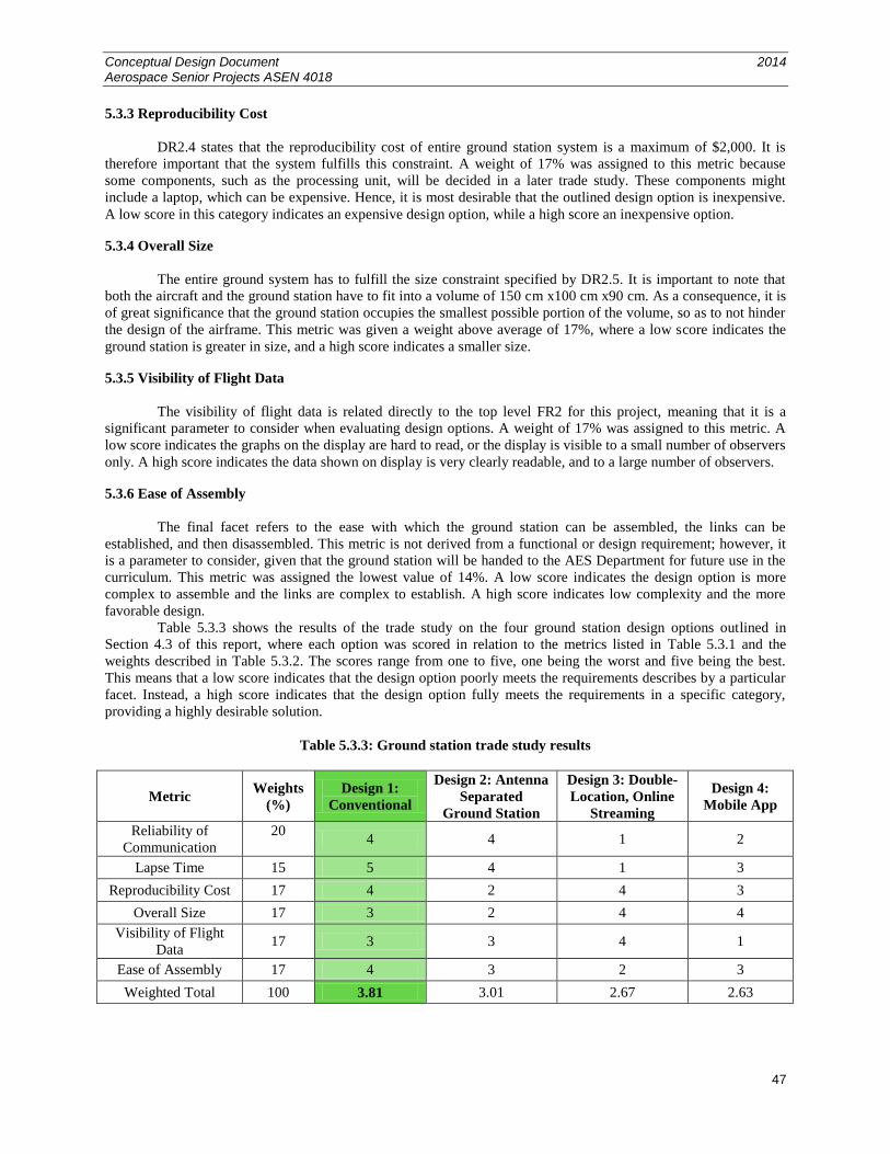
Conceptual Design Document 2014 Aerospace Senior Projects ASEN 4018
47
5.3.3 Reproducibility Cost
DR2.4 states that the reproducibility cost of entire ground station system is a maximum of $2,000. It is
therefore important that the system fulfills this constraint. A weight of 17% was assigned to this metric because
some components, such as the processing unit, will be decided in a later trade study. These components might
include a laptop, which can be expensive. Hence, it is most desirable that the outlined design option is inexpensive.
A low score in this category indicates an expensive design option, while a high score an inexpensive option.
5.3.4 Overall Size
The entire ground system has to fulfill the size constraint specified by DR2.5. It is important to note that
both the aircraft and the ground station have to fit into a volume of 150 cm x100 cm x90 cm. As a consequence, it is
of great significance that the ground station occupies the smallest possible portion of the volume, so as to not hinder
the design of the airframe. This metric was given a weight above average of 17%, where a low score indicates the
ground station is greater in size, and a high score indicates a smaller size.
5.3.5 Visibility of Flight Data
The visibility of flight data is related directly to the top level FR2 for this project, meaning that it is a
significant parameter to consider when evaluating design options. A weight of 17% was assigned to this metric. A
low score indicates the graphs on the display are hard to read, or the display is visible to a small number of observers
only. A high score indicates the data shown on display is very clearly readable, and to a large number of observers.
5.3.6 Ease of Assembly
The final facet refers to the ease with which the ground station can be assembled, the links can be
established, and then disassembled. This metric is not derived from a functional or design requirement; however, it
is a parameter to consider, given that the ground station will be handed to the AES Department for future use in the
curriculum. This metric was assigned the lowest value of 14%. A low score indicates the design option is more
complex to assemble and the links are complex to establish. A high score indicates low complexity and the more
favorable design.
Table 5.3.3 shows the results of the trade study on the four ground station design options outlined in
Section 4.3 of this report, where each option was scored in relation to the metrics listed in Table 5.3.1 and the
weights described in Table 5.3.2. The scores range from one to five, one being the worst and five being the best.
This means that a low score indicates that the design option poorly meets the requirements describes by a particular
facet. Instead, a high score indicates that the design option fully meets the requirements in a specific category,
providing a highly desirable solution.
Table 5.3.3: Ground station trade study results
Metric Weights
(%)
Design 1:
Conventional
Design 2: Antenna
Separated
Ground Station
Design 3: Double-
Location, Online
Streaming
Design 4:
Mobile App
Reliability of
Communication
20 4 4 1 2
Lapse Time 15 5 4 1 3
Reproducibility Cost 17 4 2 4 3
Overall Size 17 3 2 4 4
Visibility of Flight
Data 17 3 3 4 1
Ease of Assembly 17 4 3 2 3
Weighted Total 100 3.81 3.01 2.67 2.63
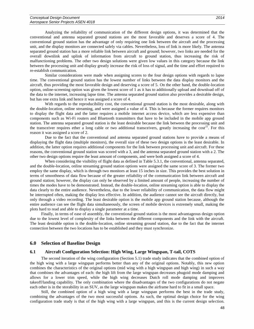
Conceptual Design Document 2014 Aerospace Senior Projects ASEN 4018
48
Analyzing the reliability of communication of the different design options, it was determined that the
conventional and antenna separated ground stations are the most favorable and deserves a score of 4. The
conventional ground station has the advantage of only requiring one link between the aircraft and the processing
unit, and the display monitors are connected safely via cables. Nevertheless, loss of link is more likely. The antenna
separated ground station has a more reliable link between aircraft and ground; however, two links are needed for the
overall downlink and uplink of information from aircraft to ground station, thus increasing the risk of
malfunctioning problems. The other two design solutions were given low values in this category because the link
between the processing unit and display greatly increase the risk of loss of signal, and the time and effort required to
re-establish communication.
Similar considerations were made when assigning scores to the four design options with regards to lapse
time. The conventional ground station has the lowest number of links between the data display monitors and the
aircraft, thus providing the most favorable design and deserving a score of 5. On the other hand, the double-location
option, online-screening option was given the lowest score of 1 as it has to additionally upload and download off of
the data to the internet, increasing lapse time. The antenna separated ground station also provides a desirable design,
but has one extra link and hence it was assigned a score of 4.
With regards to the reproducibility cost, the conventional ground station is the most desirable, along with
the double-location, online streaming, and were assigned a value of 4. This is because the former requires monitors
to display the flight data and the latter requires a mobile internet access device, which are less expensive than
components such as Wi-Fi routers and Bluetooth transmitters that have to be included in the mobile app ground
station. The antenna separated ground station is the least desirable because the link between the processing unit and
the transceiver requires ether a long cable or two additional transceivers, greatly increasing the cost21
. For this
reason it was assigned a score of 2.
Due to the fact that the conventional and antenna separated ground stations have to provide a means of
displaying the flight data (multiple monitors), the overall size of these two design options is the least desirable. In
addition, the latter option requires additional components for the link between processing unit and aircraft. For these
reasons, the conventional ground station was scored with a 3, and the antenna separated ground station with a 2. The
other two design options require the least amount of components, and were both assigned a score of 4.
When considering the visibility of flight data as defined in Table 5.3.1, the conventional, antenna separated,
and the double-location, online streaming ground station options were assigned the same score of 3. The former two
employ the same display, which is through two monitors at least 15 inches in size. This provides the best solution in
terms of smoothness of data flow because of the greater reliability of the communication link between aircraft and
ground station; however, the display can only be observed by a limited amount of people, increasing the number of
times the modes have to be demonstrated. Instead, the double-location, online streaming option is able to display the
data clearly to the entire audience. Nevertheless, due to the lower reliability of communication, the data flow might
be interrupted often, making the display less effective. In addition, the audience cannot see the aircraft directly, but
only through a video recording. The least desirable option is the mobile app ground station because, although the
entire audience can see the flight data simultaneously, the screen of mobile devices is extremely small, making the
plots hard to read and able to display a single parameter at a time.
Finally, in terms of ease of assembly, the conventional ground station is the most advantageous design option
due to the lowest level of complexity of the links between the different components and the link with the aircraft.
The least desirable option is the double-location, online streaming ground station, due to the fact that the internet
connection between the two locations has to be established and they must synchronize.
6.0 Selection of Baseline Design
6.1 Aircraft Configuration Selection: High Wing, Large Wingspan, T-tail, COTS
The second iteration of the wing configuration (Section 5.1) trade study indicates that the combined option of
the high wing with a large wingspan performs better than any of the original options. Notably, this new option
combines the characteristics of the original options (mid wing with a high wingspan and high wing) in such a way
that combines the advantages of each: the high lift from the large wingspan decreases phugoid mode damping and
allows for a lower trim speed, while the high wing decreases Dutch roll mode damping and improves
takeoff/landing capability. The only combination where the disadvantages of the two configurations do not negate
each other is in the storability in an SUV, as the large wingspan makes the airframe hard to fit in a small space.
Still, the combined option of a high wing with a large wingspan performs the best in the trade study,
combining the advantages of the two most successful options. As such, the optimal design choice for the wing
configuration trade study is that of the high wing with a large wingspan, and this is the current design selection.
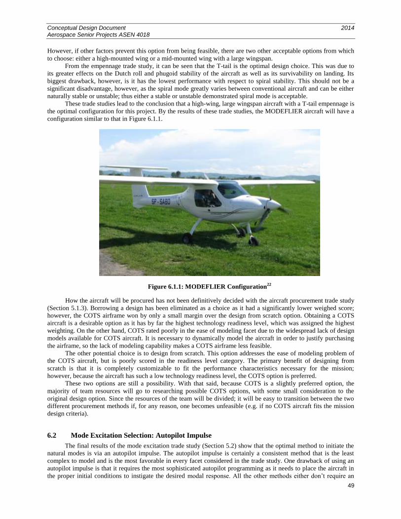
Conceptual Design Document 2014 Aerospace Senior Projects ASEN 4018
49
However, if other factors prevent this option from being feasible, there are two other acceptable options from which
to choose: either a high-mounted wing or a mid-mounted wing with a large wingspan.
From the empennage trade study, it can be seen that the T-tail is the optimal design choice. This was due to
its greater effects on the Dutch roll and phugoid stability of the aircraft as well as its survivability on landing. Its
biggest drawback, however, is it has the lowest performance with respect to spiral stability. This should not be a
significant disadvantage, however, as the spiral mode greatly varies between conventional aircraft and can be either
naturally stable or unstable; thus either a stable or unstable demonstrated spiral mode is acceptable.
These trade studies lead to the conclusion that a high-wing, large wingspan aircraft with a T-tail empennage is
the optimal configuration for this project. By the results of these trade studies, the MODEFLIER aircraft will have a
configuration similar to that in Figure 6.1.1.
Figure 6.1.1: MODEFLIER Configuration22
How the aircraft will be procured has not been definitively decided with the aircraft procurement trade study
(Section 5.1.3). Borrowing a design has been eliminated as a choice as it had a significantly lower weighed score;
however, the COTS airframe won by only a small margin over the design from scratch option. Obtaining a COTS
aircraft is a desirable option as it has by far the highest technology readiness level, which was assigned the highest
weighting. On the other hand, COTS rated poorly in the ease of modeling facet due to the widespread lack of design
models available for COTS aircraft. It is necessary to dynamically model the aircraft in order to justify purchasing
the airframe, so the lack of modeling capability makes a COTS airframe less feasible.
The other potential choice is to design from scratch. This option addresses the ease of modeling problem of
the COTS aircraft, but is poorly scored in the readiness level category. The primary benefit of designing from
scratch is that it is completely customizable to fit the performance characteristics necessary for the mission;
however, because the aircraft has such a low technology readiness level, the COTS option is preferred.
These two options are still a possibility. With that said, because COTS is a slightly preferred option, the
majority of team resources will go to researching possible COTS options, with some small consideration to the
original design option. Since the resources of the team will be divided; it will be easy to transition between the two
different procurement methods if, for any reason, one becomes unfeasible (e.g. if no COTS aircraft fits the mission
design criteria).
6.2 Mode Excitation Selection: Autopilot Impulse
The final results of the mode excitation trade study (Section 5.2) show that the optimal method to initiate the
natural modes is via an autopilot impulse. The autopilot impulse is certainly a consistent method that is the least
complex to model and is the most favorable in every facet considered in the trade study. One drawback of using an
autopilot impulse is that it requires the most sophisticated autopilot programming as it needs to place the aircraft in
the proper initial conditions to instigate the desired modal response. All the other methods either don’t require an
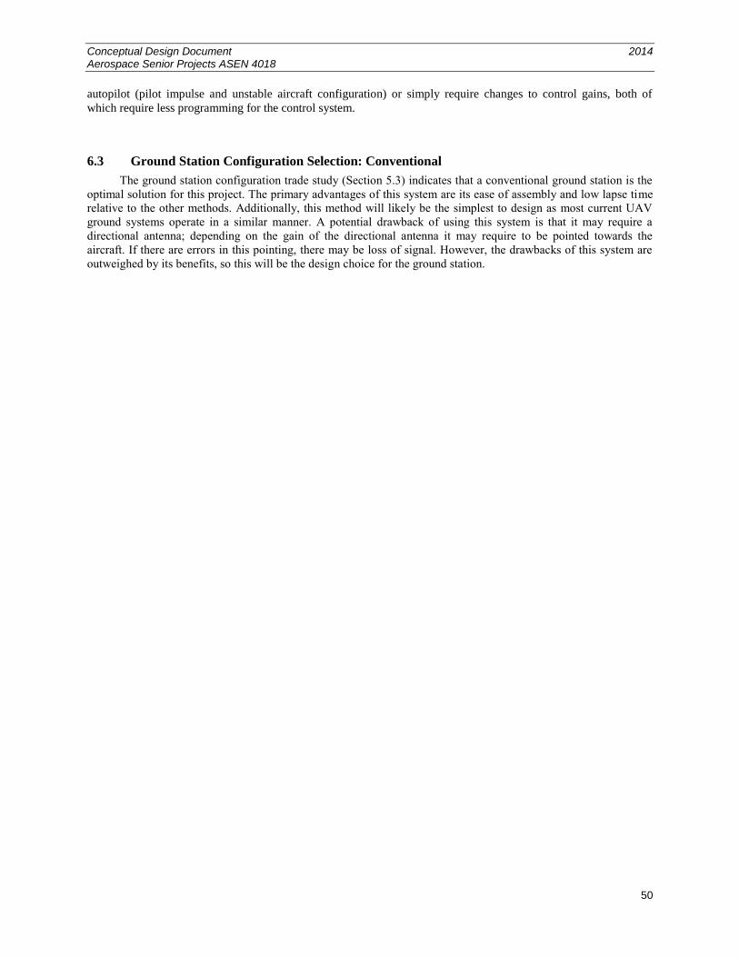
Conceptual Design Document 2014 Aerospace Senior Projects ASEN 4018
50
autopilot (pilot impulse and unstable aircraft configuration) or simply require changes to control gains, both of
which require less programming for the control system.
6.3 Ground Station Configuration Selection: Conventional
The ground station configuration trade study (Section 5.3) indicates that a conventional ground station is the
optimal solution for this project. The primary advantages of this system are its ease of assembly and low lapse time
relative to the other methods. Additionally, this method will likely be the simplest to design as most current UAV
ground systems operate in a similar manner. A potential drawback of using this system is that it may require a
directional antenna; depending on the gain of the directional antenna it may require to be pointed towards the
aircraft. If there are errors in this pointing, there may be loss of signal. However, the drawbacks of this system are
outweighed by its benefits, so this will be the design choice for the ground station.
Conceptual Design Document 2014 Aerospace Senior Projects ASEN 4018
51
7.0 References
1. Etkin, B., and Reid, L. D., Dynamics of Flight: Stability and Control, 3rd
ed., John Wiley & Sons, Inc.,
Hoboken, NJ, 1996, Chaps. 2-6.
2. Austin, R., Unmanned Aircraft Systems: UAV Design, Development and Deployment, Wiley, West Sussex,
UK, 2010, Chap. 9.
3. “AdagioTM
280 BNF Basic with AS3X® Technology,” Horizon Hobby, URL:
http://www.horizonhobby.com/ProductDisplay?product_identifier_token=product&urlRequestType=Base
&productId=255465&catalogId=10001&categoryId=11140&errorViewName=ProductDisplayErrorView&
urlLangId=-1&langId=-1&top_category=10001&parent_category_rn=11020&storeId=10151 [cited 29
Sept. 2014].
4. Anderson, D., “Dihedral: Why? How Much and Where,” Anderson Designs, URL:
http://www.mnbigbirds.com/images/PDF%20Files/Dihedral_Art.pdf [cited 29 Sept. 2014].
5. “F4U Corsair S BNF with SAFE® Technology,” Horizon Hobby, URL:
http://www.horizonhobby.com/f4u-corsair-s-bnf-with-safe-reg%3B-technology-hbz8280 [cited 29 Sept.
2014].
6. “NexSTAR 46 ARF,” Tower Hobbies, URL:
http://www.towerhobbies.com/products/hobbico/hcaa2025.html [cited 29 Sept. 2014].
7. “Super Falcon 120 - 63 Nitro Gas Radio Remote Controlled R/C Pusher Jet Plane,” Nitro Planes, URL:
http://www.nitroplanes.com/fa120nigasje.html [cited 29 Sept. 2014].
8. “Empennage,” Wikipedia, URL: http://en.wikipedia.org/wiki/Empennage [cited 29 Sept. 2014].
9. “Chapter 5 Dynamic Stability,” Cornell University, URL:
https://courses.cit.cornell.edu/mae5070/DynamicStability.pdf [cited 29 Sept. 2014].
10. Raymer, Daniel P., Aircraft Design: A Conceptual Approach, 5th
ed., Reston, VA, American Institute of
Aeronautics and Astronautics, 2012.
11. “NEW Aerobatic Airplane – Extra 260,” FUYAN R/C MODEL, URL:
http://www.fuyuanrc.com/info.asp?id=175 [cite 29 Sept. 2014].
12. “Dutch Roll,” DUTCHOPS, URL: http://www.dutchops.com/Plane_Tech/Flight%20Controls/Side-
Effects/Dutch-Roll.html [cited 29 Sept. 2014].
13. “Vertical Stability, (Yawing),” Flight Training Handbook, Aviation Online Magazine, 1965, URL:
http://avstop.com/ac/flighttrainghandbook/verticalstability.html [cited 29. Sept. 2014].
14. “Solius RR, Hi Performance Glider w/T-Tail,” Hobby Zone, URL:
http://secure.hobbyzone.com/test3/mpu264264.html?gclid=CIKv-_fwhcECFcRcMgoduGIAeQ [cited 29
Sept. 2014].
15. “Great Planes ElectriFly Siren Hotliner EP ARF GPMA1065,” RC Planet, URL:
http://www.rcplanet.com/GP_ElectriFly_Siren_Hotliner_EP_ARF_79_p/gpma1065.htm?gclid=CIuR1ufwh
cECFeVaMgodoVIAAg [cited 29 Sept. 2014].
16. “MEGATECH Prowler 3 Channel R/C Glider,” Madison Art Shop, URL:
http://www.madisonartshop.com/prowler3-channelrc-
glider.html?utm_source=googleshopping&utm_medium=cse&gclid=COewubnyhcECFaY-MgodGSkAFQ
[cited 29 Sept. 2014].
17. “Research Areas,” RECUV, University of Colorado at Boulder, URL:
http://recuv.colorado.edu/research.html [cited 29 Sept. 2014].
Conceptual Design Document 2014 Aerospace Senior Projects ASEN 4018
52
18. “Aircraft Modes of Vibration,” Aerospace Students, URL:
http://aerostudents.com/files/flightDynamics/aircraftModesOfVibration.pdf [cited 29 Sept. 2014].
19. “2-Way Bluetooth® Adaptor,” Sony, URL: http://store.sony.com/2-way-bluetooth-adaptor-zid27-
HWSBTA2W/cat-27-catid-All-TV-AV-Cables [cited 29 Sept. 2014].
20. Henry, A., “Five Best Home Wi-Fi Routers,” lifehacker, URL: http://lifehacker.com/5920709/five-best-
home-wi-fi-routers [cited 29 Sept. 2014].
21. “SFP-10G-SR,” PC Wholesale, URL: http://www.pc-wholesale.com/sfp-10g-
sr.html?gclid=CKSr2vOzh8ECFeZAMgodbFsA3w [cited 29 Sept. 2014].
22. “Aero-Kros MP-02 Czajka at Aero 2010,” Polish Aircraft Blog, URL:
http://polishaircraftblog.blogspot.com/2010/04/aero-kros-mp-02-czajka-at-aero-2010.html [cited 29 Sept.
2014].
23. “Visual Acuity,” Encyclopædia Britannica, Encyclopædia Britannica Inc., 2006.
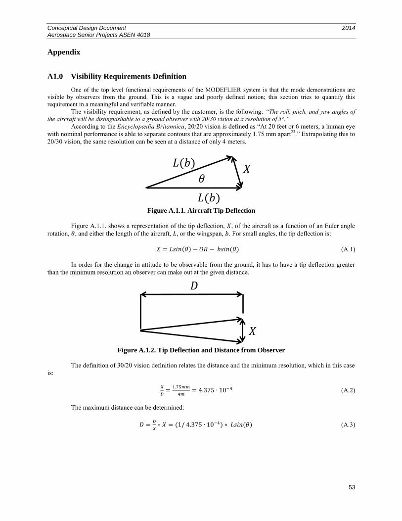
Conceptual Design Document 2014 Aerospace Senior Projects ASEN 4018
53
Appendix
A1.0 Visibility Requirements Definition
One of the top level functional requirements of the MODEFLIER system is that the mode demonstrations are
visible by observers from the ground. This is a vague and poorly defined notion; this section tries to quantify this
requirement in a meaningful and verifiable manner.
The visibility requirement, as defined by the customer, is the following: “The roll, pitch, and yaw angles of
the aircraft will be distinguishable to a ground observer with 20/30 vision at a resolution of 5°.”
According to the Encyclopædia Britannica, 20/20 vision is defined as “At 20 feet or 6 meters, a human eye
with nominal performance is able to separate contours that are approximately 1.75 mm apart23
.” Extrapolating this to
20/30 vision, the same resolution can be seen at a distance of only 4 meters.
Figure A.1.1. Aircraft Tip Deflection
Figure A.1.1. shows a representation of the tip deflection, , of the aircraft as a function of an Euler angle
rotation, , and either the length of the aircraft, , or the wingspan, . For small angles, the tip deflection is:
(A.1)
In order for the change in attitude to be observable from the ground, it has to have a tip deflection greater
than the minimum resolution an observer can make out at the given distance.
Figure A.1.2. Tip Deflection and Distance from Observer
The definition of 30/20 vision definition relates the distance and the minimum resolution, which in this case
is:
(A.2)
The maximum distance can be determined:
(A.3)
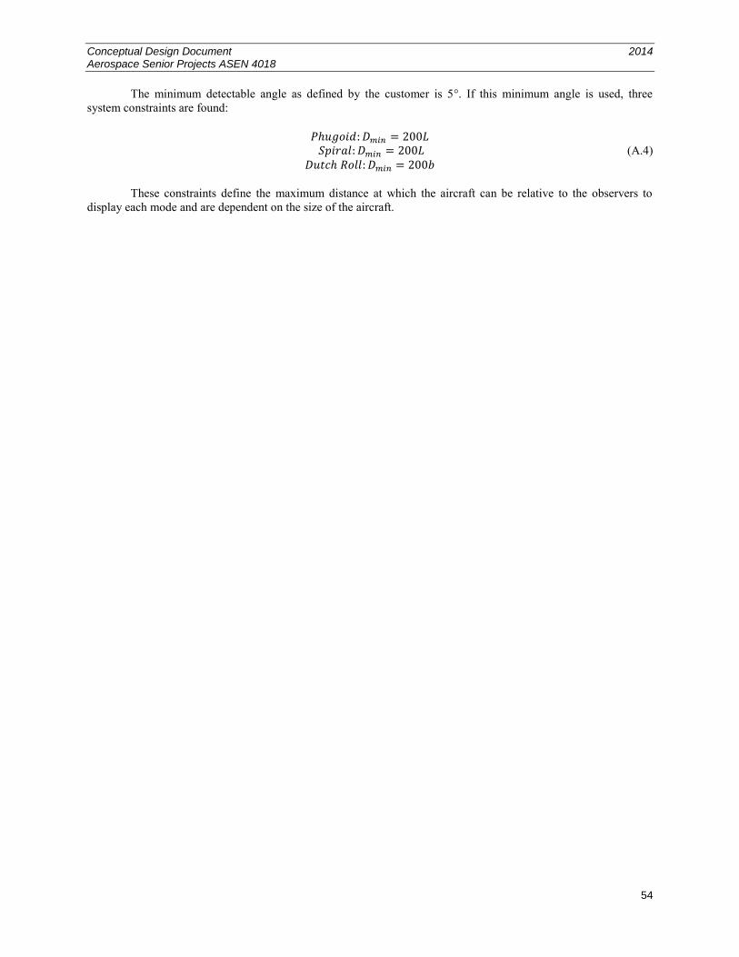
Conceptual Design Document 2014 Aerospace Senior Projects ASEN 4018
54
The minimum detectable angle as defined by the customer is 5°. If this minimum angle is used, three
system constraints are found:
(A.4)
These constraints define the maximum distance at which the aircraft can be relative to the observers to
display each mode and are dependent on the size of the aircraft.