Embed Size (px)
Citation preview

UNIVERSITY OF CALIFORNIA
SANTA CRUZ
CEPH: RELIABLE, SCALABLE, AND HIGH-PERFORMANCEDISTRIBUTED STORAGE
A dissertation submitted in partial satisfaction of therequirements for the degree of
DOCTOR OF PHILOSOPHY
in
COMPUTER SCIENCE
by
Sage A. Weil
December 2007
The Dissertation of Sage A. Weilis approved:
Professor Scott A. Brandt, Chair
Doctor Richard Golding
Professor Charlie McDowell
Professor Carlos Maltzahn
Professor Ethan L. Miller
Lisa C. SloanVice Provost and Dean of Graduate Studies

Copyright c© by
Sage A. Weil
2007

Table of Contents
List of Figures vii
List of Tables xiv
Abstract xv
Dedication xvii
Acknowledgments xviii
1 Introduction 11.1 Contributions . . . . . . . . . . . . . . . . . . . . . . . . . . . . . . . . . . . 31.2 Outline . . . . . . . . . . . . . . . . . . . . . . . . . . . . . . . . . . . . . . 5
2 Related Work 72.1 Local File Systems . . . . . . . . . . . . . . . . . . . . . . . . . . . . . . . . 72.2 Client-Server File Systems . . . . . . . . . . . . . . . . . . . . . . . . . . . . 102.3 Distributed File Systems . . . . . . . . . . . . . . . . . . . . . . . . . . . . . 11
2.3.1 Wide-area File Systems . . . . . . . . . . . . . . . . . . . . . . . . . 122.3.2 SAN File Systems . . . . . . . . . . . . . . . . . . . . . . . . . . . . 132.3.3 Object and Brick-based Storage . . . . . . . . . . . . . . . . . . . . . 132.3.4 Non-POSIX Systems . . . . . . . . . . . . . . . . . . . . . . . . . . . 15
3 Ceph Architecture 173.1 Ceph . . . . . . . . . . . . . . . . . . . . . . . . . . . . . . . . . . . . . . . . 173.2 Client Operation . . . . . . . . . . . . . . . . . . . . . . . . . . . . . . . . . . 20
3.2.1 File I/O and Capabilities . . . . . . . . . . . . . . . . . . . . . . . . . 213.2.2 Client Synchronization . . . . . . . . . . . . . . . . . . . . . . . . . . 223.2.3 Namespace Operations . . . . . . . . . . . . . . . . . . . . . . . . . . 24
3.3 Communication Model . . . . . . . . . . . . . . . . . . . . . . . . . . . . . . 25
iii

4 Distributed Metadata Management 274.1 Background and Related Work . . . . . . . . . . . . . . . . . . . . . . . . . . 30
4.1.1 Local File Systems . . . . . . . . . . . . . . . . . . . . . . . . . . . . 304.1.2 Distributed File Systems . . . . . . . . . . . . . . . . . . . . . . . . . 32
4.2 Metadata Storage . . . . . . . . . . . . . . . . . . . . . . . . . . . . . . . . . 374.2.1 Embedded Inodes . . . . . . . . . . . . . . . . . . . . . . . . . . . . . 394.2.2 Remote Links and the Anchor Table . . . . . . . . . . . . . . . . . . . 404.2.3 Large Journals . . . . . . . . . . . . . . . . . . . . . . . . . . . . . . 41
4.3 Adaptive Workload Distribution . . . . . . . . . . . . . . . . . . . . . . . . . 424.3.1 Subtree Partitioning as Soft State . . . . . . . . . . . . . . . . . . . . 434.3.2 Metadata Replication . . . . . . . . . . . . . . . . . . . . . . . . . . . 464.3.3 Locking . . . . . . . . . . . . . . . . . . . . . . . . . . . . . . . . . . 474.3.4 Load Balance . . . . . . . . . . . . . . . . . . . . . . . . . . . . . . . 484.3.5 Subtree Migration . . . . . . . . . . . . . . . . . . . . . . . . . . . . 494.3.6 Directory Fragments . . . . . . . . . . . . . . . . . . . . . . . . . . . 504.3.7 Traffic Control . . . . . . . . . . . . . . . . . . . . . . . . . . . . . . 52
4.4 Failure Recovery . . . . . . . . . . . . . . . . . . . . . . . . . . . . . . . . . 534.4.1 Journal Structure . . . . . . . . . . . . . . . . . . . . . . . . . . . . . 544.4.2 Failure Detection . . . . . . . . . . . . . . . . . . . . . . . . . . . . . 554.4.3 Recovery . . . . . . . . . . . . . . . . . . . . . . . . . . . . . . . . . 554.4.4 Discussion . . . . . . . . . . . . . . . . . . . . . . . . . . . . . . . . 59
4.5 Evaluation . . . . . . . . . . . . . . . . . . . . . . . . . . . . . . . . . . . . . 594.5.1 Metadata Partitioning . . . . . . . . . . . . . . . . . . . . . . . . . . . 604.5.2 Embedded Inodes . . . . . . . . . . . . . . . . . . . . . . . . . . . . . 654.5.3 Journaling . . . . . . . . . . . . . . . . . . . . . . . . . . . . . . . . . 694.5.4 Adaptive Distribution . . . . . . . . . . . . . . . . . . . . . . . . . . . 714.5.5 Metadata Scaling . . . . . . . . . . . . . . . . . . . . . . . . . . . . . 724.5.6 Failure Recovery . . . . . . . . . . . . . . . . . . . . . . . . . . . . . 744.5.7 Availability . . . . . . . . . . . . . . . . . . . . . . . . . . . . . . . . 77
4.6 Future Work . . . . . . . . . . . . . . . . . . . . . . . . . . . . . . . . . . . . 784.7 Experiences . . . . . . . . . . . . . . . . . . . . . . . . . . . . . . . . . . . . 794.8 Conclusions . . . . . . . . . . . . . . . . . . . . . . . . . . . . . . . . . . . . 80
5 Data Distribution 825.1 Related Work . . . . . . . . . . . . . . . . . . . . . . . . . . . . . . . . . . . 845.2 The CRUSH algorithm . . . . . . . . . . . . . . . . . . . . . . . . . . . . . . 86
5.2.1 Hierarchical Cluster Map . . . . . . . . . . . . . . . . . . . . . . . . . 875.2.2 Replica Placement . . . . . . . . . . . . . . . . . . . . . . . . . . . . 885.2.3 Map Changes and Data Movement . . . . . . . . . . . . . . . . . . . . 955.2.4 Bucket Types . . . . . . . . . . . . . . . . . . . . . . . . . . . . . . . 96
5.3 Evaluation . . . . . . . . . . . . . . . . . . . . . . . . . . . . . . . . . . . . . 1045.3.1 Data Distribution . . . . . . . . . . . . . . . . . . . . . . . . . . . . . 1045.3.2 Reorganization and Data Movement . . . . . . . . . . . . . . . . . . . 107
iv

5.3.3 Algorithm Performance . . . . . . . . . . . . . . . . . . . . . . . . . 1095.3.4 Reliability . . . . . . . . . . . . . . . . . . . . . . . . . . . . . . . . . 112
5.4 Future Work . . . . . . . . . . . . . . . . . . . . . . . . . . . . . . . . . . . . 1135.5 Conclusions . . . . . . . . . . . . . . . . . . . . . . . . . . . . . . . . . . . . 114
6 Distributed Object Storage 1166.1 Overview . . . . . . . . . . . . . . . . . . . . . . . . . . . . . . . . . . . . . 1176.2 Distributed Object Storage . . . . . . . . . . . . . . . . . . . . . . . . . . . . 121
6.2.1 Data Placement . . . . . . . . . . . . . . . . . . . . . . . . . . . . . . 1226.2.2 Cluster Maps . . . . . . . . . . . . . . . . . . . . . . . . . . . . . . . 1246.2.3 Communication and Failure Model . . . . . . . . . . . . . . . . . . . 1266.2.4 Monitors . . . . . . . . . . . . . . . . . . . . . . . . . . . . . . . . . 1276.2.5 Map Propagation . . . . . . . . . . . . . . . . . . . . . . . . . . . . . 129
6.3 Reliable Autonomic Storage . . . . . . . . . . . . . . . . . . . . . . . . . . . 1306.3.1 Replication . . . . . . . . . . . . . . . . . . . . . . . . . . . . . . . . 1306.3.2 Serialization versus Safety . . . . . . . . . . . . . . . . . . . . . . . . 1326.3.3 Maps and Consistency . . . . . . . . . . . . . . . . . . . . . . . . . . 1336.3.4 Versions and Logs . . . . . . . . . . . . . . . . . . . . . . . . . . . . 1356.3.5 Failure Recovery . . . . . . . . . . . . . . . . . . . . . . . . . . . . . 1366.3.6 Client Locking and Caching . . . . . . . . . . . . . . . . . . . . . . . 142
6.4 Performance and Scalability . . . . . . . . . . . . . . . . . . . . . . . . . . . 1446.4.1 Scalability . . . . . . . . . . . . . . . . . . . . . . . . . . . . . . . . 1476.4.2 Failure Recovery . . . . . . . . . . . . . . . . . . . . . . . . . . . . . 151
6.5 Future Work . . . . . . . . . . . . . . . . . . . . . . . . . . . . . . . . . . . . 1536.6 Related Work . . . . . . . . . . . . . . . . . . . . . . . . . . . . . . . . . . . 1556.7 Conclusions . . . . . . . . . . . . . . . . . . . . . . . . . . . . . . . . . . . . 161
7 Local Object Storage 1627.1 Object Storage Interface . . . . . . . . . . . . . . . . . . . . . . . . . . . . . 1627.2 Data Layout . . . . . . . . . . . . . . . . . . . . . . . . . . . . . . . . . . . . 1647.3 Data Safety . . . . . . . . . . . . . . . . . . . . . . . . . . . . . . . . . . . . 1647.4 Journaling . . . . . . . . . . . . . . . . . . . . . . . . . . . . . . . . . . . . . 1657.5 Evaluation . . . . . . . . . . . . . . . . . . . . . . . . . . . . . . . . . . . . . 1667.6 Related Work . . . . . . . . . . . . . . . . . . . . . . . . . . . . . . . . . . . 1677.7 Conclusion . . . . . . . . . . . . . . . . . . . . . . . . . . . . . . . . . . . . 168
8 Conclusion 1698.1 Future Work . . . . . . . . . . . . . . . . . . . . . . . . . . . . . . . . . . . . 169
8.1.1 MDS Load Balancing . . . . . . . . . . . . . . . . . . . . . . . . . . 1698.1.2 Client Interaction . . . . . . . . . . . . . . . . . . . . . . . . . . . . . 1708.1.3 Security . . . . . . . . . . . . . . . . . . . . . . . . . . . . . . . . . . 1718.1.4 Quotas . . . . . . . . . . . . . . . . . . . . . . . . . . . . . . . . . . 1718.1.5 Quality of Service . . . . . . . . . . . . . . . . . . . . . . . . . . . . 171
v

8.1.6 Snapshots . . . . . . . . . . . . . . . . . . . . . . . . . . . . . . . . . 1728.2 Summary . . . . . . . . . . . . . . . . . . . . . . . . . . . . . . . . . . . . . 172
A Communications Layer 175A.1 Abstract Interface . . . . . . . . . . . . . . . . . . . . . . . . . . . . . . . . . 175A.2 SimpleMessenger . . . . . . . . . . . . . . . . . . . . . . . . . . . . . . . . . 176A.3 FakeMessenger . . . . . . . . . . . . . . . . . . . . . . . . . . . . . . . . . . 176
B MDS Implementation Details 178B.1 MDS Distributed Cache . . . . . . . . . . . . . . . . . . . . . . . . . . . . . . 178
B.1.1 Cache Structure . . . . . . . . . . . . . . . . . . . . . . . . . . . . . . 179B.1.2 Replication and Authority . . . . . . . . . . . . . . . . . . . . . . . . 182B.1.3 Subtree Partition . . . . . . . . . . . . . . . . . . . . . . . . . . . . . 183
B.2 Metadata Storage . . . . . . . . . . . . . . . . . . . . . . . . . . . . . . . . . 185B.2.1 Directory Fragments and Versioning . . . . . . . . . . . . . . . . . . . 185B.2.2 Journal Entries . . . . . . . . . . . . . . . . . . . . . . . . . . . . . . 187B.2.3 Anchor Table . . . . . . . . . . . . . . . . . . . . . . . . . . . . . . . 188
B.3 Migration . . . . . . . . . . . . . . . . . . . . . . . . . . . . . . . . . . . . . 189B.3.1 Cache Infrastructure . . . . . . . . . . . . . . . . . . . . . . . . . . . 189B.3.2 Normal Migration . . . . . . . . . . . . . . . . . . . . . . . . . . . . 192
B.4 Failure Recovery . . . . . . . . . . . . . . . . . . . . . . . . . . . . . . . . . 194B.4.1 Journal Replay . . . . . . . . . . . . . . . . . . . . . . . . . . . . . . 195B.4.2 Resolve Stage . . . . . . . . . . . . . . . . . . . . . . . . . . . . . . . 195B.4.3 Reconnect Stage . . . . . . . . . . . . . . . . . . . . . . . . . . . . . 197B.4.4 Rejoin Stage . . . . . . . . . . . . . . . . . . . . . . . . . . . . . . . 197
B.5 Anchor Table . . . . . . . . . . . . . . . . . . . . . . . . . . . . . . . . . . . 201B.5.1 Table Updates . . . . . . . . . . . . . . . . . . . . . . . . . . . . . . . 201B.5.2 Failure Recovery . . . . . . . . . . . . . . . . . . . . . . . . . . . . . 201
Bibliography 203
vi

List of Figures
3.1 System architecture. Clients perform file I/O by communicating directly with
OSDs. Each process can either link directly to a client instance, or interactwith
a mounted file system. . . . . . . . . . . . . . . . . . . . . . . . . . . . . . . 18
4.1 All metadata for each directory, including file names (dentries) and the inodes
they reference, are stored in a single object (identified by the directory’s inode
number) in the shared, distributed object store. Inode 1 is the root directory. . . 38
4.2 Structure of the metadata cache as seen by a single MDS. Metadata is par-
titioned into subtrees bounded by directory fragments. Each MDS replicates
ancestor metadata for any locally managed subtrees. Large or busy directories
are be broken into multiple fragments, which can then form nested subtrees.. . 45
4.3 Directories are fragmented based on a tree in which each interior node has a
2n children, and leaves correspond to individual fragments. Fragments are de-
scribed by a bit pattern and mask, like an IP subnet, partitioning an integer
namespace. Dentries are assigned to a specific fragment using a hash functions. 51
4.4 MDS performance as file system, cluster size, and client base are scaled. . . . . 61
vii

4.5 Percentage of cache devoted to ancestor inodes as the file system, client base
and MDS cluster size scales. Hashed distributions devote large portions oftheir
caches to ancestor directories. The dynamic subtree partition has slightly more
ancestors than the static partition due to the re-delegation of subtrees nested
within the hierarchy. . . . . . . . . . . . . . . . . . . . . . . . . . . . . . . . 62
4.6 Cache hit rate as a function of cache size (as a fraction of total file system size).
For smaller caches, inefficient cache utilization due to replicated ancestorsre-
sults in lower hit rates. . . . . . . . . . . . . . . . . . . . . . . . . . . . . . . 63
4.7 No traffic control (top): nodes forward all requests to the authoritative MDS
who slowly responds to them in sequence. Traffic control (bottom): the author-
itative node quickly replicates the popular item and all nodes respond to requests. 64
4.8 Cumulative directory size for a variety of static file system snapshots. Many
directories are very small (or even empty), and less than 5% contain more than
100 entries. . . . . . . . . . . . . . . . . . . . . . . . . . . . . . . . . . . . . 66
4.9 Study of hard link prevalence in file system snapshots. For each snapshot, the
total file system size and the percentage of files with multiple links are shown.
Stacked bars indicate the fraction of multilink files with all links in the same di-
rectory, with parallel cohorts linked by multiple directories, or with no obvious
locality properties. . . . . . . . . . . . . . . . . . . . . . . . . . . . . . . . . 67
viii

4.10 An MDS cluster adapts to a varying workload. At times 200 and 350 the work-
load shifts, as 400 clients begin creating files in private directories and thenin
a shared directory. In both cases load is redistributed, in the latter case after the
large (and busy) directory is fragmented. At time 280 two additional MDSs join
the cluster. . . . . . . . . . . . . . . . . . . . . . . . . . . . . . . . . . . . . . 71
4.11 Per-MDS throughput under a variety of workloads and cluster sizes. As the
cluster grows to 128 nodes, efficiency drops no more than 50% below perfect
linear (horizontal) scaling for most workloads, allowing vastly improved per-
formance over existing systems. . . . . . . . . . . . . . . . . . . . . . . . . . 72
4.12 Average latency versus per-MDS throughput for different cluster sizes (makedirs
workload). . . . . . . . . . . . . . . . . . . . . . . . . . . . . . . . . . . . . 74
4.13 Throughput in a small cluster before, during, and after MDS failures at time
400, 500, and two at 450. Unresponsive nodes are declared dead after 15 sec-
onds, and in each case recovery for a 100 MB journal takes 4-6 seconds. . . . . 75
4.14 Per-MDS throughput in a 4-node cluster under a compilation workloadwith
heavy read sharing of/lib. Replication of popular metadata allows progress
to continue even when the MDS managing the heavily shared directory suffers
a failure. . . . . . . . . . . . . . . . . . . . . . . . . . . . . . . . . . . . . . . 77
5.1 A partial view of a four-level cluster map hierarchy consisting of rows,cabinets,
and shelves of disks. Bold lines illustrate items selected by eachselectoperation
in the placement rule and fictitious mapping described by Table 5.1. . . . . . . 91
ix

5.2 Reselection behavior ofselect(6,disk)when devicer = 2 (b) is rejected, where
the boxes contain the CRUSH output~R of n = 6 devices numbered by rank.
The left shows the “first n” approach in which device ranks of existing devices
(c,d,e, f ) may shift. On the right, each rank has a probabilistically independent
sequence of potential targets; herefr = 1, andr ′ = r + frn = 8 (deviceh). . . . 94
5.3 Data movement in a binary hierarchy due to a node addition and the subsequent
weight changes. . . . . . . . . . . . . . . . . . . . . . . . . . . . . . . . . . . 96
5.4 Node labeling strategy used for the binary tree comprising each tree bucket. . . 100
5.5 Efficiency of reorganization after adding or removing storage devices two levels
deep into a four level, 7290 device CRUSH cluster hierarchy, versus RUSHP
and RUSHT . 1 is optimal. . . . . . . . . . . . . . . . . . . . . . . . . . . . . 108
5.6 Efficiency of reorganization after adding items to different bucket types. 1 is
optimal. Straw and list buckets are normally optimal, although removing items
from the tail of a list bucket induces worst case behavior. Tree bucket changes
are bounded by the logarithm of the bucket size. . . . . . . . . . . . . . . . . .109
5.7 CRUSH and RUSHT computation times scale logarithmically relative to hierar-
chy size, while RUSHP scales linearly. . . . . . . . . . . . . . . . . . . . . . . 110
5.8 Low-level speed of mapping replicas into individual CRUSH buckets versus
bucket size. Uniform buckets take constant time, tree buckets take logarithmic
time, and list and straw buckets take linear time. . . . . . . . . . . . . . . . . . 111
x

6.1 A cluster of many thousands of OSDs store all objects in the system. A small,
tightly coupled cluster of monitors collectively manages the cluster map that
describes the current cluster composition and the distribution of data. Each
client instance exposes a simple storage interface to applications. . . . . . . .. 118
6.2 Objects are grouped intoplacement groups(PGs), and distributed to OSDs via
CRUSH, a specialized replica placement function. Failed OSDs (e. g. osd1)
are filtered out of the final mapping. . . . . . . . . . . . . . . . . . . . . . . . 122
6.3 Replication strategies implemented by RADOS. Primary-copy processes both
reads and writes on the first OSD and updates replicas in parallel, while chain
forwards writes sequentially and processes reads at the tail. Splay replication
combines parallel updates with reads at the tail to minimize update latency. . . 131
6.4 RADOS responds with anack after the write has been applied to the buffer
caches on all OSDs replicating the object (shown here with splay replication).
Only after it has been safely committed to disk is a secondcommitnotification
sent to the client. . . . . . . . . . . . . . . . . . . . . . . . . . . . . . . . . . 132
6.5 Each PG has a log summarizing recent object updates and deletions. The
most recently applied operation is indicated bylast update. All updates above
last completeare known to have been applied, while any missing objects in the
interval betweenlast completeand last updateare summarized in the missing
list. . . . . . . . . . . . . . . . . . . . . . . . . . . . . . . . . . . . . . . . . 134
xi

6.6 Reads in shared read/write workloads are usually unaffected by writeopera-
tions. However, reads of uncommitted data can be delayed until the update
commits. This increases read latency in certain cases, but maintains a fully
consistent behavior for concurrent read and write operations in the event that
all OSDs in the placement group simultaneously fail and the writeack is not
delivered. . . . . . . . . . . . . . . . . . . . . . . . . . . . . . . . . . . . . . 143
6.7 Per-OSD write performance. The horizontal line indicates the upper limit im-
posed by the physical disk. Replication has minimal impact on OSD through-
put, although if the number of OSDs is fixed,n-way replication reduces total
effectivethroughput by a factor ofn because replicated data must be written to
n OSDs. . . . . . . . . . . . . . . . . . . . . . . . . . . . . . . . . . . . . . . 144
6.8 Write latency for varying write sizes and primary-copy replication. Morethan
two replicas incurs minimal additional cost for small writes because replicated
updates occur concurrently. For large synchronous writes, transmission times
dominate. Clients partially mask that latency for writes over 128 KB by acquir-
ing exclusive locks and asynchronously flushing the data. . . . . . . . . .. . . 145
6.9 Latency for 4 KB writes under different replication strategies and levels of repli-
cation. Splay replication augments chain replication with parallel replica up-
dates to achieve performance similar to primary-copy replication for high levels
of replication. . . . . . . . . . . . . . . . . . . . . . . . . . . . . . . . . . . . 146
xii

6.10 Normalized write latency per replica for 1 MB writes under different replication
strategies and levels of replication. Parallel replication does not improve latency
for replications levels below six. . . . . . . . . . . . . . . . . . . . . . . . . . 147
6.11 OSD write performance scales linearly with the size of the OSD cluster until
the switch is saturated at 24 OSDs. CRUSH and hash performance improves
when more PGs lower variance in OSD utilization. . . . . . . . . . . . . . . . 148
6.12 Duplication of map updates received by individual OSDs as the size ofthe clus-
ter grows. The number of placement groups on each OSD effects numberof
peers it has who may share map updates. . . . . . . . . . . . . . . . . . . . . . 151
6.13 Write throughput over time as a saturated 20 OSD cluster recovers from two
OSD failures at time 30. Data re-replication begins at time 50 and completes at
time 80. . . . . . . . . . . . . . . . . . . . . . . . . . . . . . . . . . . . . . . 152
6.14 Write throughput over time as an unsaturated 20 OSD cluster recoversfrom one
OSD failure at time 30 and two more at time 80. . . . . . . . . . . . . . . . . . 152
7.1 Performance of EBOFS compared to general-purpose file systems. Although
small writes suffer from coarse locking in the prototype, EBOFS nearly satu-
rates the disk for writes larger than 32 KB. Since EBOFS lays out data in large
extents when it is written in large increments, it has significantly better read
performance. . . . . . . . . . . . . . . . . . . . . . . . . . . . . . . . . . . . 166
xiii

List of Tables
5.1 A simple rule that distributes three replicas across three cabinets in the samerow. 91
5.2 Summary of mapping speed and data reorganization efficiency of different bucket
types when items are added to or removed from a bucket. . . . . . . . . . . . . 97
5.3 As the total utilization of available storage approaches capacity, the number
of devices that would otherwise overfill and that require adjustment increases.
CRUSH computation increases slightly while decreasing variance. . . . . . . .106
6.1 Data elements present in the OSD cluster map, which describes both cluster
state and the distribution of data. . . . . . . . . . . . . . . . . . . . . . . . . . 125
B.1 Sample anchor table with two anchored inodes. Note that the full path is shown
only for illustration and is not part of the table. The hash mark (#) in the parent
column is used to denote a particular fragment of the given directory, where 0
indicates the directory is not fragmented. The /usr entry has a ref count of two
because it is referenced by both /usr/bin and /usr/lib. . . . . . . . . . . . . . .. 189
xiv

Abstract
Ceph: Reliable, Scalable, and High-performance DistributedStorage
by
Sage A. Weil
As the size and performance requirements of storage systems have increased, file
system designers have looked to new architectures to facilitate system scalability. The emerging
object-based storage paradigm diverges from server-based (e. g. NFS) and SAN-based storage
systems by coupling processors and memory with disk drives, allowing systems to delegate low-
level file system operations (e. g. allocation and scheduling) to object storage devices (OSDs)
and decouple I/O (read/write) from metadata (file open/close) operations.Even recent object-
based systems inherit a variety of decades-old architectural choices going back to early UNIX
file systems, however, limiting their ability to effectively scale.
This dissertation shows that device intelligence can be leveraged to providereliable,
scalable, and high-performance file service in a dynamic cluster environment. It presents a dis-
tributed metadata management architecture that provides excellent performance and scalability
by adapting to highly variable system workloads while tolerating arbitrary node crashes. A
flexible and robust data distribution function places data objects in a large, dynamic cluster of
storage devices, simplifying metadata and facilitating system scalability, while providing a uni-
form distribution of data, protection from correlated device failure, and efficient data migration.
This placement algorithm facilitates the creation of a reliable and scalable object storage ser-
vice that distributes the complexity of consistent data replication, failure detection, and recovery

across a heterogeneous cluster of semi-autonomous devices.
These architectural components, which have been implemented in the Ceph distributed
file system, are evaluated under a variety of workloads that show superior I/O performance,
scalable metadata management, and failure recovery.

To Elise and Riley,
who make it all worthwhile,
and to my parents, to whom I owe so much.
xvii

Acknowledgments
I would like to thank my advisor, Scott Brandt, and Carlos Maltzahn for their invalu-
able guidance, support, and friendship over these past few years.
I thank Ethan Miller for his collaboration and guidance in my research, and for
his help in editing this thesis. I gratefully acknowledge Darrell Long, Richard Golding, and
Theodore Wong for their excellent suggestions for my work. I thank Charlie McDowell for his
generous service on my committee.
I would like to thank the students of the SSRC for their support and friendship. Kristal
Pollack, Feng Wang, Chris Xin, Andrew Leung, Chris Olson, Joel Wu, Tim Bisson, and Rosie
Wacha have provided a stimulating and challenging environment, and have allbeen a pleasure
to work with over the years.
Finally, I would like to thank Bill Loewe and Tyce McLarty for their continued sup-
port. In particular, their generous lobbying on my behalf helped secure access to computing
resources at LLNL that were extremely helpful in my research.
This research was supported by Lawrence Livermore National Laboratory.
xviii

Chapter 1
Introduction
System designers have long sought to improve the performance of file systems, which
have proved critical to the overall performance of an exceedingly broad class of applications.
The scientific and high-performance computing communities in particular have driven advances
in the performance and scalability of distributed storage systems, typically predicting more
general purpose needs by a few years. Traditional solutions, exemplified by NFS [72], provide a
straightforward model in which a server exports a file system hierarchy that clients can map into
their local name space. Although widely used, the centralization inherent in the client/server
model has proven a significant obstacle to scalable performance.
More recent distributed file systems have adopted architectures based onobject-based
storage, in which conventional hard disks are replaced with intelligent object storage devices
(OSDs) which combine a CPU, network interface, and local cache with an underlying disk or
RAID [14, 30, 31, 104, 107]. OSDs replace the traditional block-levelinterface with one in
which clients can read or write byte ranges to much larger (and often variably sized) named
1

objects, distributing low-level block allocation decisions to the devices themselves. Clients
typically interact with a metadata server (MDS) to perform metadata operations(open, rename),
while communicating directly with OSDs to perform file I/O (reads and writes), significantly
improving overall scalability.
Systems adopting this model continue to suffer from scalability limitations due to
little or no distribution of the metadata workload. Continued reliance on traditionalfile system
principles like allocation lists and inode tables and a reluctance to delegate intelligence to the
OSDs have further limited scalability and performance, and increased the cost of reliability.
I have developed a prototype for Ceph [100], a distributed file system that provides
excellent performance, reliability, and scalability. The architecture is based on the assumption
that systems at the petabyte scale are inherently dynamic: large systems are inevitably built
incrementally, node failures are the norm rather than the exception, and thequality and character
of workloads are constantly shifting over time.
Ceph decouples data and metadata operations by eliminating file allocation tables
and replacing them with a novel generating function. This allows Ceph to leverage the intel-
ligence present in OSDs to distribute the complexity surrounding data access, update serial-
ization, replication and reliability, failure detection, and recovery. Ceph utilizes an adaptive
distributed metadata cluster architecture that streamlines common metadata operations while
dramatically improving the scalability of metadata access, and with it, the scalability ofthe
entire system. I discuss the goals and workload assumptions motivating choices in the design
of the architecture, analyze their impact on system scalability, performance, and reliability, and
relate experiences in implementing a functional system prototype.
2

1.1 Contributions
The thesis of this dissertation is that device intelligence can be leveraged to provide
reliable, scalable, and high-performance file service in a dynamic cluster environment.
The primary contributions of this dissertation are threefold.
First, I present a distributed metadata management architecture that provides excellent
performance and scalability while seamlessly tolerating arbitrary node crashes. Ceph’s MDS
diverges from conventional metadata storage techniques, and in doing so facilitates adaptive file
system and workload partitioning among servers, improved metadata availability, and failure
recovery. Specifically, file system metadata updates are initially written to large, lazily-trimmed
per-MDS journals that absorb temporary and repetitive updates. File (inode) metadata is then
embedded in the file system namespace and stored inside per-directory objects for efficient
read access and metadata prefetching. I present a comparative analysis of distributed metadata
partitioning techniques, and describe the novel dynamic subtree partitioningapproach used by
Ceph. Notably, my MDS defines the namespace hierarchy in terms of directory fragments,
facilitating fine-grained load distribution even for large or busy directories, and implements a
traffic control mechanism for dispersing load generated by flash crowds—sudden concurrent
access by thousands of client nodes—across multiple nodes in the MDS cluster.
The second contribution of this work is a robust hierarchical data distribution function
that places data in a large distributed storage system. When used in place of conventional al-
location tables, the algorithm efficiently addresses a range of critical storage-related placement
issues, including statistically uniform data distribution, correlated failure anddata safety, and
3

data migration in dynamically changing storage clusters. Specifically, the algorithm places sets
of data objects (either object replicas, or parity or erasure coded fragments) in a hierarchy of
storage devices using a flexible rule language. The flexible hierarchicalcluster description fa-
cilitates an adjustable balance between extremely efficient placement calculations and mapping
stability when devices are added or removed from the cluster. It further provides the ability to
enforce the separation of replicas across user-defined failure domains, limiting exposure to data
loss due to correlated failures.
My third contribution is a distributed object storage architecture that leverages de-
vice intelligence to provide a reliable and scalable storage abstraction with minimaloversight.
Specifically, I describe an efficient, scalable, and low-overhead cluster management protocol
that facilitates consistent and coherent data access through the propagation of small cluster
maps that specify device membership and data distribution. This allows a dynamiccluster
of semi-autonomous OSDs to self-manage consistent data replication, failuredetection, and
failure recovery while providing the illusion of a single logical object store with direct, high-
performance client access to data.
These contributions have been implemented as part of the Ceph file system proto-
type. The prototype is written in roughly 40,000 semicolon-lines of C++ code and has been
released as open source under the Lesser GNU Public License (LGPL)to serve as a reference
implementation and research platform.
4

1.2 Outline
The remainder of this dissertation is structured as follows.
Chapter 2 introduces past and existing approaches to file system design.General ar-
chitectural issues affecting performance, scalability, and reliability are introduced, and in certain
cases related to Ceph’s contributions. In general, however, specifically related work is discussed
in context in the chapters that follow.
Chapter 3 introduces the Ceph architecture and key design features. The overall op-
eration of the system is described from the perspective of a client performing basic file system
operations in order to provide an overview of how the various system components interact.
Chapter 4 describes the design, implementation, and performance characteristics of
Ceph’s metadata server (MDS). I focus on the design implications of Ceph’s unconventional
approach to file (inode) storage and update journaling on metadata storage, dynamic workload
distribution, and failure recovery. A variety of static file system snapshotsand workload traces
are analyzed to motivate design decisions and performance analysis, andperformance is eval-
uated under a range of micro-benchmarks and workloads under both normal-use and failure
scenarios.
Chapter 5 describes CRUSH, the special-purpose data placement algorithm used by
Ceph to distribute data among object storage devices. Specifically, I address the problem of
managing data layout in large, dynamic clusters of devices by eliminating conventional alloca-
tion maps and replacing them with a low-costfunction. A variety of issues related to scalability,
data safety, and performance are considered.
5

Chapter 6 introduces RADOS, Ceph’s Reliable Autonomic Distributed Object Store.
RADOS provides an extremely scalable storage cluster management platformthat exposes a
simple object storage abstraction. System components utilizing the object storecan expect
scalable, reliable, and high-performance access to objects without concerning themselves with
the details of replication, data redistribution (when cluster membership expands or contracts),
failure detection, or failure recovery.
Chapter 7 describes EBOFS, the low-level object storage library utilized by RADOS
to efficiently manage collections of objects on locally attached disks.
Finally, Chapter 8 provides some concluding remarks and describes avenues of con-
tinued research.
6

Chapter 2
Related Work
This research draws upon a large body of experience and researchwith file and storage
systems. This includes experience with local file systems (which interact with locally attached
disks), network file systems that interact with a remote server, and a rangeof distributed file
system architectures in which file system data is spread across multiple hosts.
2.1 Local File Systems
File system design over the past three decades has been heavily influenced by the
original Unix file system, and the Fast File System (FFS) [65] found in BSD Unix. The in-
terface and behavior—semantics—of these early file systems formed the basis of the POSIX
SUS (Single Unix Specification) standard [12] to which most modern systems and applications
conform.
BSD’s FFS, like most “local” file systems, is designed to operate on a locally attached
hard disk storing fixed-size sectors or blocks. (In contrast, Ceph is a “cluster” file system that
7
operates on a large number of hosts connected by a network.) Hard disksat the time were
slow to “seek” or position themselves over a given block, but once positioned could read data
relatively quickly. To avoid positioning delays as much as possible, FFS featured cylinder
groups, representing localized regions of disk falling within the same cylindrical regions of the
spinning hard disk platter. Related data and metadata were stored in the same cylinder group,
such that most seeks involved minimal repositioning of the disk arm.
Over the past few decades, disk performance has increased significantly. However,
positioning latencies have dropped much more slowly than disk transfer rateshave increased,
making careful layout of data on disk even more important than before. The desire to reduce
position latencies motivated the design of the Log-structured File System (LFS)in the Sprite
network operating system [26, 78]. LFS avoided positioning delays for write workloads by
laying out new data on disk in a sequential log. Metadata structures were periodically flushed to
disk (in the log) to allow previously written data to be located and re-read. However, in order to
reclaim disk space from deleted files, LFS required a “cleaner” to relocate partially deallocated
regions of the log, which degraded performance under many workloads[87, 88].
DualFS [73] separates data and metadata storage—not unlike object-based cluster file
systems—by writing metadata to a separate device using an LFS-style log, mitigating cleaner
effects by eliminating bulky file data. Although—as with LFS—a special inode mapfile is re-
quired to translate inode numbers to locations on disk, DualFS improves metadataperformance
by storing recently modified dentries and inodes close together in the log.
Although the cylinder group concept has been refined over the years,the basic meta-
data structures and allocation strategies introduced by FFS still persist in typical local file sys-
8

tems, such as ext3 [95]. As file system sizes have scaled more quickly than hard disk archi-
tectures, metadata structures have adapted. For example, file sizes have increased while disk
block sizes have remained small—usually 4 KB—for efficient storage of smallfiles. For large
files, this gives rise to extremely long block allocation lists enumerating the locationof file
data. Modern local file systems are exemplified by XFS [92], which replaces allocation lists
with extents—start and length pairs—to compactly describe large regions of disk.
Modern file systems have also introduced reliability features to streamline fastrecov-
ery after a failure. As with most commonly used alternatives, XFS maintains an on-diskjournal
file that it uses to log metadata updates that it is about to perform. In the eventof a failure,
the journal can be read to ensure that updates were successfully and correctly applied, or clean
up any partially applied updates. Although journals come with a performance penalty—disks
have to frequently reposition themselves to append to the journal, and each metadata update is
written to disk twice—they avoid the need for more costly consistency checks during failure
recovery (which are increasingly expensive as file systems scale).
Many systems also implement a form ofsoft updates, in which modifications are
written only to unallocated regions of disk and in careful order to ensure that the on-disk image
is always consistent (or easily repaired) [64]. The WAFL file system [40], for example, uses a
copy-on-write approach when update the hierarchical metadata structures, writing all new data
to unallocated regions of disk, such that changes are committed by simply updating a pointer to
the root tree node. WAFL also maintains a journal-like structure, but does so only to preserve
update durability between commits, not to maintain file system consistency. A similar technique
is used by EBOFS, the object-storage component of Ceph (see Chapter 7).
9

2.2 Client-Server File Systems
The desire to share storage resources and data in networked computing environments
has given rise to a number of client-server file systems. The most commonly used are NFS [72]
and CIFS [38], which allow a central server to “export” a local file system to remote systems,
who then map it into their own namespace. Centralizing storage has facilitated thecreation
of specialized, high-performance storage systems and popularized so-called NAS—network
attached storage. However, the centralization inherent the client-serverarchitecture has proved
a significant impediment to scalability, because all file system operations much be processed
by a single server. In large installations, administrators typically assign subsets of their data
to specific servers, and map them into a single namespace by mounting multiple servers on
each client. While reasonably effective and widespread, this approachcan cause administrative
headaches when certain data sets grow or contract and require manuallymigration to other
servers.
Networked file systems typically relax consistency semantics in order to preserve
cache performance in a distributed environment. For example, NFS clients write file data back
to the server asynchronously, such that concurrent file access from other client hosts may not
always return the most recent copy of data. Similarly, clients typically cachefile metadata (e. g.
as seen bystat) for a fixed interval to limit client interact with and load on the file server. This
relaxation of file system consistency can cause problems for many applications, precluding their
use in NFS-based environments.
10

2.3 Distributed File Systems
Distributed file systems attempt to address the fundamental load balancing and scaling
challenges inherent in client-server systems. Early distributed file systems include AFS [43],
Coda [85], and that found in Sprite [71]. These utilize a central serverto coordinate file system
access, and issueleasesto explicitly promise the validity of data (or metadata) provided to the
client cache for a specified period, while subsequentcallbackscan revoke the promise in the
event of a conflicting access. However, while Sprite simply disabled caching in the event of
(relatively rare) write sharing, AFS adopts an alternative consistency model constrained by file
open and close instead of individual read and write events. In contrast,NFS (prior to version
4, which adds limited lease-like support for file “delegations”) is stateless bydesign, sacrificing
consistency in the presence of data sharing.
Sprite partitions the file system among different servers by statically separating the
namespace into “domains,” and dynamically mapping each to server. AFS utilizes a hybrid
scheme that partitions files based on both their name and identifier among volumes, each of
which is then assigned to a server. In both systems, partition boundaries are visible to the user
through the lack of support forlink or atomicrename. In contrast to these systems, Ceph aims
to provide a unified file system namespace and fully consistent POSIX semantics.
Distributed architectures frequently replicate data across multiple servers for relia-
bility and availability in the presence of failure. In the Harp [61] file system, servers employ
primary-copy replication and write-ahead logs to allow fast recovery in theevent of a node
failure. A range of storage subsystems use similar techniques to provide reliable block-based
11

access to storage. Petal [56] provides a sparse virtual disk abstraction that is managed by a
dynamic cluster of servers. FAB [82] employs a replica consistency protocol based on major-
ity voting. Ceph similarly provides a distributed and consistent storage service with (unlike
Petal) an object-based interface, a comparatively simple (relative to FAB) replica consistency
protocol, and greater scalability (see Chapter 6).
Much like local file systems leverage RAID for reliability, systems like Frangipani [94]
exploit a reliable distributed storage-layer abstraction like Petal to build a distributed file sys-
tem. Boxwood [63] similarly provides a file service based on reliable, replicated block devices,
although it does so by first constructing a rich distributed B-tree data structure. Ceph takes a
somewhat analogous approach with its use of the RADOS abstraction to provide reliable and
scalable storage, although it uses an object-based (rather than block-based) interface (see Sec-
tion 2.3.3).
2.3.1 Wide-area File Systems
Many systems consider distribution of file system components over a wide areaor
even (in some cases) in a global environment. The xFS [99] file system used an invalidation-
based cache-consistency protocol to facilitate aggressive client caching, in certain cases al-
lowing reads from peer’s caches [23, 22], to minimize costly communication over wide-area
networks, though with a significant cost in complexity. The OceanStore [52] file system aims
to build a globally available file storage service with erasure codes and a location-independent
routing abstraction. Pangaea [83] targets a similar wide-area environment,aggressively repli-
cating file contents where they are read, while relaxing replica consistencywhere strong guaran-
12

tees are not explicitly required. All of these systems focus largely on minimizingcostly network
communication (in some cases at the expense of consistency) and scalability over a wide area;
high-performance access to in a clustered environment—where network communication is rel-
atively cheap—is not a design goal as it is in Ceph.
2.3.2 SAN File Systems
Recognizing that most file I/O in inherently parallel—that is, I/O to different files is
unrelated semantically—most recent “cluster” file systems are based on the basic idea of shared
access to underlying storage devices. So-called SAN—storage area network—file systems are
based on hard disks or RAID controllers communicating via a fibre channel(or similar) network,
allowing any connected host to issue commands to any connected disk.
Most SAN file systems utilize a distributed lock manager (DLM) [51] to coordinate
access to shared block storage. Additional steps are taken to limit the probability of lock con-
tention, exemplified by the partial distribution of block allocation in GPFS [86]. Other systems,
such as StorageTank [66], recognizing that contention for locks protecting file system metadata
can limit scalability, utilize an auxiliary cluster of servers for managing file systemmetadata—
the hierarchical namespace, access control, and block allocation.
2.3.3 Object and Brick-based Storage
Recently, many file systems and platforms, including Federated Array of Bricks (FAB) [82],
PVFS [55], and pNFS [39] have been designed around clusters of network attached storage
servers [31]. Like StorageTank, metadata is managed by an independent server (or servers),
13

but file I/O takes place by interacting directly with a cluster of storage servers (often termed
“bricks”) instead of fibre channel disks. This allows certain functionality—such as low-level
block allocation decisions—to be distributed to the devices themselves.
Lustre [14], the Panasas file system [104], zFS [76], Sorrento [93], Ursa Minor [1],
and Kybos [107] are based on the closely-related object-based storage paradigm [7] popular-
ized by NASD [33]. Instead of performing I/O in terms of small, fixed-size blocks, data is
instead stored inobjectsthat have a name (typically taken from a flat 128-bit namespace),
a variable size (anywhere from bytes to gigabytes), and other per-object metadata, such as
named attributes describing access permissions. Object-based storage allows easily distributed
functionality like low-level block allocation or security capability enforcementto be performed
by semi-intelligent devices, reducing contention on servers managing metadata and improving
overall system scalability.
Although these object-based systems most closely resemble Ceph, none of them has
the combination of scalable and adaptable metadata management, reliability, and fault tolerance
that Ceph provides. Lustre and Panasas in particular delegate responsibility for low-level block
allocation to OSDs, reducing the amount of file metadata, but otherwise do little to exploit
device intelligence. With the exception of Sorrento, all of these systems use explicit allocation
maps to specify where objects are stored, an approach that forces the involvement of the object
directory server(s) in any migration of data between storage devices, limitingefficiency. Like
Ceph, Sorrento uses a function to describe data placement on storage nodes instead of relying on
traditional allocation tables. However, Sorrento’s hashed distribution [47] lacks Ceph’s support
for efficient data migration, device weighting, and separation of replicas across failure domains
14

(see Chapter 5). Most importantly, Ceph’s functional specification of data layout allows OSDs
to manage migration and failure recovery in a distributed fashion (see Chapter 6).
Kybos leverages device intelligence to manage quality-of-service reservations (some-
thing that Ceph does not do), and stores data using a network RAID protocol with two-phase
updates (Ceph uses a simpler replication protocol). Ursa Minor provides adistributed object
storage service that supports a range of redundancy strategies—including replication and parity-
based encoding (RAID)—and consistency models, depending on application requirements. All
of these systems, however, have limited support for efficient distributed metadata management,
limiting their scalability and performance (see Chapter 4).
2.3.4 Non-POSIX Systems
A number of distributed file systems adopt alternative (non-POSIX) file system in-
terfaces. Farsite [2, 25] federates a large number of unreliable workstations into a distributed
file system providing Windows file service with Byzantine fault-tolerance. Notably, this does
not include support for files linked to multiple names in the hierarchy (so-called “hard links”).
However, like Ceph, Farsite dynamically distributes management of the file system namespace
among available servers; dynamic subtree partitioning is discussed in greater detail in Chapter 4.
The Sorrento [93] file system is POSIX-like, but—much like AFS—adopts a relaxed
consistency model that simplifies metadata management and update consistencyin the presence
of write sharing. Other systems simplify consistency more drastically: Cedar [32] translates
the consistency problem into one of versioning by making shared files immutable, while in
Venti [75], all data is considered immutable.
15

Although architecturally the Google File System [30] resembles object-basedsys-
tems, it eschews standard file system interfaces entirely, and is optimized forvery large files
and a workload consisting largely of reads and file appends.
16

Chapter 3
Ceph Architecture
This chapter introduces the basic architectural features of Ceph. The overall operation
of the system is presented by describing the Ceph client, and its interaction withvarious system
components while performing basic file operations.
3.1 Ceph
The Ceph file system has three main components: the client, each instance of which
exposes a near-POSIX file system interface to a host or process; a cluster of OSDs, which
collectively stores all data and metadata; and a metadata server cluster, which manages the
namespace (file names and directories) while coordinating security, consistency and coherence
(see Figure 3.1). I say the Ceph interface is near-POSIX because I findit appropriate to extend
the interface and selectively relax consistency semantics in order to better align both with the
needs of applications and improve system performance (discussed in Section 3.2.2).
The primary goals of the architecture are scalability (to hundreds of petabytes and
17

Metadata
storage
File I/O
Metadata Cluster
Object Storage Cluster
clientbash
Linux kernel
fusevfs
libfusels
…
clientbash
Linux kernel
fusevfs
libfusels
…
myproc
client
myproc
client
ClientsMetadata operations
Figure 3.1: System architecture. Clients perform file I/O by communicating directly withOSDs. Each process can either link directly to a client instance, or interactwith a mounted filesystem.
beyond), performance, and reliability. Scalability is considered in a varietyof dimensions, in-
cluding the overall storage capacity and throughput of the system, and performance in terms
of individual clients, directories, or files. Our target workload may include such extreme cases
as tens or hundreds of thousands of hosts concurrently reading fromor writing to the same
file or creating files in the same directory. Such scenarios, common in scientificapplications
running on supercomputing clusters, are increasingly indicative of tomorrow’s general purpose
workloads. More importantly, distributed file system workloads are inherently dynamic, with
significant variation in data and metadata access as active applications and data sets change over
time. Ceph directly addresses the issue of scalability while simultaneously achieving high per-
formance, reliability and availability through three fundamental design features: decoupled data
and metadata, dynamic distributed metadata management, and reliable autonomic distributed
object storage.
• Decoupled Data and Metadata—Ceph maximizes the separation of file system meta-
data management from the storage of file data. Metadata operations (open, rename,
etc.) are collectively managed by a metadata server cluster, while clients interact di-
18
rectly with OSDs to perform file I/O (reads and writes). Object-based storage has long
promised to improve the scalability of file systems by delegating low-level block allo-
cation decisions to individual devices. However, in contrast to existing object-based file
systems [14, 104, 31, 30] which replace long per-file block lists with shorter object lists,
Ceph eliminates allocation lists entirely. Instead, a simple function is used to name the
objects containing file data based on inode number, byte range, and stripingstrategy,
while a special-purpose data distribution function assigns objects to specificstorage de-
vices. This allows any party to calculate (rather than look up) the name and location of
objects comprising a file’s contents, eliminating the need to maintain and distribute object
lists, simplifying the design of the system, and reducing the metadata cluster workload.
• Dynamic Distributed Metadata Management—Because file system metadata opera-
tions make up as much as half of typical file system workloads [77], effective meta-
data management is critical to overall system performance. Ceph utilizes a novel meta-
data cluster architecture based on dynamic subtree partitioning [102] that adaptively and
intelligently distributes responsibility for managing the file system directory hierarchy
among tens or even hundreds of MDSs. A (dynamic) hierarchical partitionpreserves lo-
cality in each MDS’s workload, facilitating efficient updates and aggressive prefetching
to improve performance for common workloads. Significantly, the workload distribution
among metadata servers is based entirely on current access patterns, allowing Ceph to
effectively utilize available MDS resources under any workload and achieve near-linear
metadata performance scaling in the number of MDSs.
19

• Reliable Autonomic Distributed Object Storage—Large systems composed of many
thousands of devices are inherently dynamic: they are built incrementally; they grow and
contract as new storage is deployed and old devices are decommissioned;device failures
are frequent and expected; and large volumes of data are created, moved, and deleted. All
of these factors require that the distribution of data evolve to effectively utilize available
resources and maintain the desired level of data replication. Ceph delegatesresponsibility
for data migration, replication, failure detection, and failure recovery to thecluster of
OSDs that is storing the data, while at a high level, OSDs collectively provide asingle
distributed and reliable object store to clients and metadata servers. This approach allows
Ceph to more effectively leverage the intelligence (CPU and memory) present on each
OSD to achieve reliable, highly available object storage with linear scaling.
3.2 Client Operation
I introduce the overall operation and interaction of Ceph’s components and its inter-
action with applications by describing Ceph’s client operation. The Ceph client runs on each
host executing application code and exposes a file system interface to applications. In the Ceph
prototype, the client code runs entirely in user space and can be accessed either by linking to it
directly or as a mounted file system via FUSE (a user-space file system interface). Each client
maintains its own file data cache, independent of the kernel page or buffer caches, making it
accessible to applications that link to the client directly.
20

3.2.1 File I/O and Capabilities
When a process opens a file, the client sends a request to a node in the MDS cluster
(see Section 4.3.1). An MDS traverses the file system hierarchy to translatethe file name into
the file inode, which includes a unique inode number, the file owner, mode, size, and other
per-file metadata. If the file exists and access is granted, the MDS returns the inode number,
file size, and information about the striping strategy used to map file data into objects. The
MDS may also issue the client acapability (if it does not already have one) specifying which
read or write operations are permitted. Capabilities currently include four bitscontrolling the
client’s ability to read, cache reads, write, and buffer writes. In the future, capabilities will
include security keys allowing clients to prove to OSDs that they are authorized to read or write
data [58, 69] (the prototype currently trusts all clients). involvement in file I/O is limited to
managing capabilities to preserve file consistency and achieve proper semantics.
Ceph generalizes a range of striping strategies to map file data onto a sequence of
objects. Successivestripe unit byte blocks are assigned to the firststripe countobjects, un-
til objects reach a maximumobject sizeand we move to the next set ofstripe countobjects.
Whatever the layout (by default Ceph simply breaks files into 8 MB chunks), an additional field
specifies how many replicas are stored of each object.
To avoid any need for file allocation metadata, object names are constructedby con-
catenating the file inode number and the object number. Object replicas are then assigned to
OSDs using CRUSH, a globally known mapping function (described in detail inChapter 5).
For example, if one or more clients open a file for read-only access, an MDS grants them the
21

capability to read and cache file content. Armed with the inode number, layout, and file size,
the clients can name and locate all objects containing file data and read directly from the OSD
cluster. Any objects or byte ranges that don’t exist are defined to be file“holes”, or zeros. Sim-
ilarly, if a client opens a file for writing, it is granted the capability to write with buffering, and
any data it generates at any offset in the file is simply written to the appropriateobject on the
appropriate OSD. The client relinquishes the capability on file close and provides the MDS with
the new file size (the largest offset written), which redefines the set of objects that (may) exist
and contain file data.
3.2.2 Client Synchronization
POSIX semantics sensibly require that reads reflect any data previouslywritten, and
that writes are atomic (i. e. the result of overlapping, concurrent writes will reflect a particular
order of occurrence). When a file is opened by multiple clients with either multiplewriters or a
mix of readers and writers, the MDS will revoke any previously issued read caching and write
buffering capabilities, forcing all client I/O to be synchronous. That is,each application read or
write operation will block until it is acknowledged by the OSD, effectively placing the burden
of update serialization and synchronization with the OSD storing each object.Achieving atom-
icity is more complicated when writes span object boundaries. The prototype currently uses a
simple locking mechanism to achieve correct serialization, although an alternative method that
implements something closer to a true transaction is under consideration.
Not surprisingly, synchronous I/O can be a performance killer for applications, par-
ticularly those doing small reads or writes, due to the latency penalty—at leastone round-trip
22

to the OSD. Although read-write sharing is relatively rare in general-purpose workloads [77], it
is more common in scientific computing applications [98], where performance is often critical.
For this reason, it is often desirable to relax consistency at the expense of strict standards con-
formance in situations where applications do not rely on it. Although Ceph supports such relax-
ation via a global switch, and many other distributed file systems punt on this issue [55, 72, 93],
this is an imprecise and unsatisfying solution: either performance suffers,or consistency is lost
system-wide.
For precisely this reason, a set of high performance computing extensions to the
POSIX I/O interface have been proposed by the high-performance computing (HPC) commu-
nity [103], a subset of which are implemented by Ceph. Most notably, theseinclude anO LAZY
flag for openthat allows applications to explicitly relax the usual coherency requirements for
a shared-write file. Performance-conscious applications who manage their own consistency
(e. g. by writing to different parts of the same file, a common pattern in HPC workloads[98])
are then allowed to buffer writes or cache reads when I/O would otherwisebe performed syn-
chronously. If desired, applications can then explicitly synchronize with two additional calls:
lazyio propagatewill flush a given byte range to the object store, whilelazyio synchronizewill
ensure that the effects of previous propagations are reflected in any subsequent reads. The latter
is implemented efficiently by provisionally invalidating cached data, such that subsequent read
requests will be sent to the OSD but only return data if it is newer. The Cephsynchronization
model thus retains its simplicity by providing correct read-write and shared-write semantics be-
tween clients via synchronous I/O, and extending the application interface torelax consistency
for performance conscious distributed applications.
23

3.2.3 Namespace Operations
Client interaction with the file system namespace is managed by the metadata server
cluster. Both read operations (e. g. readdir, stat) and updates (e. g. unlink, chmod) are syn-
chronously applied by an MDS to ensure serialization, consistency, correct security, and safety.
For simplicity, no metadata locks or leases are issued to clients. For HPC workloads in particu-
lar, callbacks offer minimal upside at a high potential cost in complexity.
Instead, Ceph optimizes for the most common metadata access scenarios. Areaddir
followed by astat of each file (e. g. ls -l) is an extremely common access pattern and no-
torious performance killer in large directories. Areaddir in Ceph requires only a single MDS
request, which fetches the entire directory, including inode contents. By default, if a read-
dir is immediately followed by one or morestats, the briefly cached information is returned;
otherwise it is discarded. Although this relaxes coherence slightly in that anintervening inode
modification may go unnoticed, Ceph can optionally make this trade for vastly improved perfor-
mance. This behavior is explicitly captured by thereaddirplus[103] extension, which returns
lstat results with directory entries (as some OS-specific implementations ofgetdiralready do).
Ceph can allow consistency to be further relaxed by caching metadata longer, much
like earlier versions of NFS, which typically cache for 30 seconds. However, this approach
breaks coherency in a way that is often critical to applications, such as those usingstat to
determine if a file has been updated—they either behave incorrectly, or endup waiting for old
cached values to time out.
Ceph opts instead to again provide correct behavior and extend the interface in in-
24

stances where it adversely affects performance. This choice is most clearly illustrated by astat
operation on a file currently opened by multiple clients for writing. In order to return a correct
file size and modification time, the MDS revokes any write capabilities to momentarily stop
updates and collect up-to-date size and mtime values from all writers. The highest values are
returned with thestat reply, and capabilities are reissued to allow further progress. Although
stopping multiple writers may seem drastic, it is necessary to ensure proper serializability. (For
a single writer, a correct value can be retrieved from the writing client without interrupting
progress.) Applications who find coherent behavior unnecessary—victims of a POSIX inter-
face that doesn’t align with their needs—can opt to use the newstatliteoperation [103], which
takes a bit mask specifying which inode fields are not required to be coherent.
3.3 Communication Model
Ceph adopts an asynchronous messaging model for inter-node communication. In
contrast to systems based on RPC, outgoing messages are queued for later delivery without
blocking, and exchanges need not (and generally do not) consist of request and response pairs.
This allows for greater flexibility and efficiency in data and information flow byfacilitating
asymmetric exchanges.
The communications model assumes ordered fail-stop delivery of messagesbetween
any given pair of nodes. That is, all sent messages will be delivered intheir entirety in the order
they were sent. The implementation currently utilizes TCP, although the interfaceis constructed
to easily support alternative transports such as RDS [70]. In the eventof a communications
25

failure (e. g. a transport error, such as a break in an underlying TCP connection),the sender is
asynchronously notified of the error.
26

Chapter 4
Distributed Metadata Management
As demand for storage has increased, the centralization inherent in client-server stor-
age architectures has proven a significant obstacle to scalable performance. Recent distributed
file systems have adopted architectures based on object-based or brick-based storage, distribut-
ing low-level block allocation decisions to the storage devices and simplifying file system meta-
data. This lends itself well to architectures in which clients interact with a separate metadata
server (MDS) to perform metadata operations (e. g. open, rename) while communicating di-
rectly with storage devices (OSDs) for file I/O.
In systems that decouple data and metadata access, efficient metadata performance
becomes critical to overall system performance. Prior workload study has shown that metadata
operations account for as much as 30-70% of all file systems operations [77]. While conven-
tional write buffering and data prefetching techniques reduce interactionwith storage devices
for data I/O, metadata operations are frequently synchronous. Further, because data is managed
independently from metadata, the metadata server workload consists almost entirely of small
27

reads and writes to relatively small data structures, making it important for the MDS to optimize
its own I/O with underlying storage devices.
As distributed file systems scale to petabytes of data and beyond, the distribution
of workload becomes difficult. System capacity and workloads usually grow incrementally
over time, and can vary independently, making static partitions of the file systemto individual
servers inefficient: individual nodes may become overloaded while others sit idle. Typical
server workloads vary on a daily basis, as demand shifts throughout theday [27], and in many
systems—compute clusters in particular—workloads may vary wildly as different jobs start and
finish [98]. Such variance in file system workloads demandsadaptiveapproaches to metadata
management in order to effectively utilize resources at scale [25, 79, 100, 102].
The combined demand for metadata performance and dynamic load balancing poses
a significant challenge to system reliability. Storage systems, by their nature,demand strong
data safety, while distributed systems introduce more system components that mayfail. Most
conventional file systems employ some form ofjournal, which provides a sequential log of op-
erations that allows fast recovery after a failure. In a dedicated MDS, however, the large number
of small updates leads to a pathological I/O profile when combined with conventional metadata
storage and journaling approaches. Alternative techniques based onsoft updatesrequire careful
ordering of updates [64], limiting parallelism and placing an even greater burden on the storage
subsystem.
I present a metadata management approach addressing the unique performance re-
quirements of a clustered metadata server that is capable of tolerating arbitrary node crashes1.
1The MDS cluster is tolerant of any number or combination of MDS node crashes, provided there is sufficientopportunity for new MDS processes to recover in their place. The clusterdoes not tolerate Byzantine failures,
28

In contrast to previous work in this area, my architecture and implementation maintain meta-
data performance before, during, and after failure by simultaneously addressing the efficiency
of metadata I/O, cluster adaptability, and failure recovery.
Ceph’s metadata storage differs from that in conventional file systems in twokey
ways. First, the relatively small per-fileinodemetadata structures in our environment (due in
part to our use of an object-based storage layer that minimizes allocation metadata) make it
practical to embed them in directories with the directory entries (dentries) that refer to them,
while support for multiple pathnames referencing a single file (hard links) is preserved through
an auxiliary table. Based on prior study and my own analysis of file system snapshots and
workloads, Ceph stores each directory’s contents (dentries and embedded inodes) together in
the shared object storage pool. This facilitates inode prefetching by exploiting the high degree
of directory locality present in most workloads—with negligible additional I/O cost—and fa-
cilitates an efficient subtree-based load partitioning strategy by embedding all metadata in the
hierarchical namespace.
Second, Ceph utilizes per-metadata server update journals that are allowed to grow
very large, to hundreds of megabytes or more. This allows it to distill the effects of multiple
updates and short-lived files into a much smaller set of updates to the primary metadata struc-
tures, minimizing inefficient random-access I/O, while facilitating streamlined recovery and
subsequent MDS performance after a node failure.
Finally, I adopt a subtree-based partitioning strategy [25, 102] to dynamically dis-
tribute workload. A hierarchical approach preserves locality within eachMDS workload, while
wherein processes behave incorrectly or maliciously.
29

selective metadata replication preserves cluster throughput and availabilitywhen a subset of
nodes fail. Ceph’s approach redefines the directory hierarchy in termsof directoryfragments,
facilitating fine-grained load distribution and simple, efficient storage.
In this chapter I focus on thefailure recovery, metadata I/O efficiency, andadapt-
ability implications of the combined approach to metadata storage, journaling, and workload
distribution and relate my experiences constructing a working implementation. I analyze a
variety of static file system snapshots and workload traces to motivate MDS design and per-
formance analysis, present a simulation based-analysis of metadata partitioning approaches to
demonstrate the architectural advantages of a dynamic subtree-based approach, and evaluate
my implementation under a range of micro-benchmarks, workload traces, andfailure scenarios.
4.1 Background and Related Work
Metadata in file systems presenting a POSIX file system interface is normally repre-
sented by three basic structures: inodes, dentries, and directories. Per-file or directory metadata
(e. g.modification time, size, data location) is stored ininodes. Eachdirectoryhas some number
of file names or directory entries (dentries), each referencing an inode by number.
4.1.1 Local File Systems
In the original Unix file system, as well as BSD’s FFS [65]—whose basic design
most later file systems have largely preserved—inodes were stored in tablesin reserved regions
on disk, their precise location indicated by their inode number. In contrast, C-FFS [29] embeds
30

most inodes inside directories with the dentries that refer to them, as well as taking steps to keep
each directory’s file data together on disk. Despite significant performance benefits (10-300%),
few file systems since have adopted similar embedding techniques. This may be due to C-FFS’s
need to maintain a map of all directories to supportmultilink files(usually termedhard links)—
inodes which are referenced by multiple filenames. In contrast, our metadataserver architecture
embedsall inodes and maintains a much smaller table that indexes only those directories with
nested multilink files (we consider table utilization in detail in Section 4.5.2.3).
The Log-Structured File System (LFS) [26, 78] stores all data and metadata in a se-
quential log for improved write performance. However, the “cleaner” used to reclaim space—
by rewriting partially deallocated log segments to new regions of disk—can incur a significant
overhead for many workloads [87, 88]. DualFS [73] separates data and metadata management—
much like object-based cluster file systems—by writing metadata to a separate device using an
LFS-style log, mitigating cleaner effects by eliminating bulky file data. Although—as with
LFS—a special inode map file is required to translate inode numbers to locationson disk, Du-
alFS improves metadata locality by storing recently modified dentries and inodes close together
in the log. hFS [113] combines elements of FFS and LFS by storing metadata andsmall file
data in an LFS-like log and large file data in FFS-style allocation groups, allowing the effects of
many operations to be combined into an atomic segment write (as in LFS) while also avoiding
the need for a cleaner entirely.
Most modern file systems [92, 95] employjournaling to maintain file system con-
sistency after a crash. Metadata (and, in certain cases, data) updates are first written to a log-
structured journal before being applied to the regular on-disk metadata structures. Although
31

journals come with a performance penalty—disks have to frequently reposition themselves to
append to the journal, and each metadata update is written to disk twice—they avoid the need
for more costly consistency checks during failure recovery (which areincreasingly expensive as
file systems scale). Many systems also implement a form ofsoft updates, in which modifications
are written only to unallocated regions of disk and in careful order to ensure that the on-disk
image is always consistent (or easily repaired) [40, 64]. Ceph’s MDS combines elements of
LFS and journaling, adapted to a distributed environment.
4.1.2 Distributed File Systems
Distributed file systems must partition management of the overall file system names-
pace across multiple servers in order to scale. I discuss prior approaches in terms of the parti-
tioning strategy to introduce the efficiency issues involved.
4.1.2.1 Static Subtree Partitioning
The most common approach is to statically partition the directory hierarchy and assign
each subtree to a particular server, in some cases migrating subtrees whenit becomes necessary
to correct load imbalance—this approach is taken by Sprite [71], StorageTank [66], PanFS [68],
and others. However, because partition boundaries are typically visible through the lack oflink
and atomicrenamesupport, these systems resemblead hoccollections of NFS or CIFS [38]
servers. Static partitions fail to account for the growth or contraction of individual subtrees over
time, often requiring intervention of system administrators to repartition or (in some cases)
manually rebalance data across servers. Although StorageTank and PanFS volumes or file sets
32

are smaller than the physical server capacity and can be migrated between servers, the unit of
load distribution remains coarse and fixed.
4.1.2.2 Hash-based Partitioning
To limit workload imbalance associated with static subtree partitioning, Lustre’s clus-
tered MDS distributes directories randomly among “inode groups,” each ofwhich is assigned
to a server [14]. This provides a finer distribution of data and workload by decorrelating the
partition from the hierarchy. A number of other distributed file systems use a similarly random
distribution: Vesta [20], Intermezzo [13], RAMA [67], and zFS [76] allhash the file pathname
and/or some other unique identifier to determine the location of metadata and/or data. As long
as such a mapping is well defined, this simple strategy has a number of advantages. Clients can
locate and contact the responsible MDS directly and, for average workloads and well-behaved
hash functions, requests are evenly distributed across the cluster. Further, hot-spots of activity
in the hierarchical directory structure, such as heavy create activity in asingle directory, do not
correlate to individual metadata servers because metadata location has no relation to the direc-
tory hierarchy. However, hot-spots consisting of individual files can still overwhelm a single
responsible MDS.
More significantly, distributing metadata by hashing eliminates all hierarchical lo-
cality, and with it many of the locality benefits typical of local file systems. Some systems
distribute metadata based on a hash of thedirectory portion of a path only to allow directory
contents to be grouped on MDS nodes and on disk. This approach facilitates prefetching and
other methods of exploiting locality within the metadata workload. Even so, to satisfy POSIX
33

directory access semantics, the MDS cluster must traverse prefix (ancestor) directories contain-
ing a requested piece of metadata to ensure that the directory permissions allow the current user
access to the metadata and data in question. Because the files and directorieslocated on each
MDS are scattered throughout the directory hierarchy, a hashed metadata distribution results in
high overhead, either from a traversal of metadata scattered on multiple servers, or from the
cache of prefixes replicated locally. Prefix caches between nodes will exhibit a high degree of
overlap because parent directory inodes must be replicated for each MDS serving one or more
of their children, consuming memory resources that could cache other data.
Approaches like ANU (adaptive nonuniform randomization) [108] seek todistribute
fixed file sets (e. g. Lustre’s inode groups) among servers using a hash-like function that is
dynamically adjusted based on measured server load. As with static subtree partitions, ANU
relies on an existing fixed partition of metadata into file sets; in contrast, Ceph’sMDS balances
load using a flexible dynamic partition and heuristics similar to those in ANU to prevent load
thrashing.
4.1.2.3 Lazy Hybrid
Lazy Hybrid (LH) metadata management [15] seeks to capitalize on the benefits of a
hashed distribution while avoiding the problems associated with path traversalby merging the
net effect of the permission check into each file metadata record. Like other hashing approaches,
LH uses a hash of the file’s full path name to distribute metadata. To alleviate the potentially
high cost of traversing paths scattered across the cluster, LH uses a dual-entry access control
list that stores the effective access information for the entire path traversal with the metadata
34

for each file. It has been shown that this information can usually be represented very compactly
even for large general-purpose file systems [74]. LH need only traverse the path when access
controls need to be updated because an ancestor directory’s access permissions are changed,
affecting the effective permissions of all files nested beneath it. Similarly, renaming or moving
a directory affects the path name hash output and hence metadata location ofall files nested
beneath it, requiring metadata to be migrated between MDSs. Previous trace analysis has shown
that changes like this happen very infrequently [77] and it is likely that theywill affect small
numbers of files when they do occur. Moreover, it is possible to performthis update at a later
time to avoid a sudden burst of network activity between metadata servers, by having each MDS
maintain a log of recent updates that have not fully propagated and then lazily update nested
items as they are requested.
LH avoids path traversal in most cases, provided certain metadata operations are suffi-
ciently infrequent in the workload. Analysis has shown that update cost can be amortized to one
network trip per affected file; as long as updates are eventually applied more quickly than they
are created (changes to directories containing lots of items could trigger potentially millions of
updates with a single update), LH delivers a net savings and good scalability. Like other file
hashing approaches, it avoids overloading a single MDS in the presenceof directory hot-spots
by scattering directories. However, in doing so the locality benefits are lostwhile the system
remains vulnerable to individually popular files. More importantly, the low update overhead es-
sential to LH performance is predicated on the low prevalence of specific metadata operations,
which may not hold for all workloads.
35

4.1.2.4 Dynamic Subtree Partitioning
A few research file systems have recently adopteddynamicsubtree-based metadata
partitions, in which subtrees of the hierarchy are redistributed across a cluster of servers in re-
sponse to the current workload. The directory service in Farsite [25] dynamically redistributes
subtrees described by a hierarchical file identifier, but unlike Ceph, implements Windows (non-
POSIX) semantics, with no support for hard links. More significantly, Farsite also relies on a
hierarchical file identifier in order to minimize growth of its description of the current metadata
distribution; in contrast, Ceph requires no global state to specify the namespace partition, im-
proving scalability. Envoy [79] allows client hosts to claim management of subtrees based on
their current workload through a distributed locking strategy. Neither, however, evaluates the
comparative benefits of a subtree-based approach quantitatively, nordo either present or evalu-
ate an implementation with working failure recovery. The Farsite MDS utilizes an independent
atomic-action state machine substrate, which the authors suggest could be integrated with Far-
site’s existing Byzantine-fault tolerant substrate; the performance implications of doing so are
not discussed. A recovery procedure for Envoy is described, butnot evaluated nor considered
in the context of system performance.
4.1.2.5 Metadata Storage
Distributed approaches to metadata management commonly utilize a shared storage
subsystem, facilitating load balancing and failure recovery. However, existing approaches take
minimal steps to optimize the I/O generated by the metadata server. Because Lustre metadata in
each inode group is stored in a modified ext3 file system, the large volume of updates imposes a
36

significant random I/O load due to the use of conventional journaling and inode storage. PanFS
and Envoy, two other object-based file systems, both store each file’s metadata as attributes on
the file data objects, subjecting the distributed object store to a similar workload.
I describe a combined metadata management strategy involving embedded inodes,
large MDS journals, and dynamic subtree partitioning specifically in the context of metadata
I/O efficiency, metadata partition efficiency and adaptability, and sustained performance in the
presence of arbitrary node failure. Ceph’s evaluation is based on the study of general purpose
file system usage—content snapshots and workload traces—and evaluation of both normal op-
eration and failure recovery of a working implementation.
4.2 Metadata Storage
Metadata, like data, is stored by a cluster of object storage devices (OSDs) that form a
replicated, reliable object storage pool, described in Chapter 6. A varietyof other reliable, dis-
tributed storage layers have been discussed in the literature [1, 30, 82, 100, 107]; in this chapter
I ignore the details of object storage, assuming only that performance is based on the behavior
of modern hard disks—characterized by expensive seeks and high sequential throughput—and
focus instead on minimizing the I/O workload generated by the MDS by favoringsequential
over small, random I/Os.
The full metadata contents of each directory (file names and inodes) are stored in a
single object whose name corresponds to the directory’s inode number, as shown in Figure 4.1.
Each MDS also maintains a journal that contains recently created or modified metadata not yet
37

102
100
1
usr
etc
var
home
100
101
102
103
vmlinuz 104
passwd
mtab 202
203
hosts 201
lib
include 318
319
bin 317
…
…
Dentry Inode123Storage Object
…
Figure 4.1: All metadata for each directory, including file names (dentries) and the inodes theyreference, are stored in a single object (identified by the directory’s inode number) in the shared,distributed object store. Inode 1 is the root directory.
committed to the directory storage objects. MDS journals are striped over many fixed-size (but
large) objects with sequential identifiers. Journals grow by spilling onto newobjects, and are
trimmed by deleting older objects.
Normally, the MDS submits a separate I/O operation for each journal entry in order
to minimize the latency associated with any individual update operation. Under heavy loads,
however, journal throughput can still be limited by the storage layer due to the large number of
small (though sequential) write operations. To avoid this, the MDS will write journal data to the
object store in larger increments only when it is necessary to keep the overall I/O rate below a
fixed (tunable) maximum, improving overall throughput (and, correspondingly, average latency)
under heavy load.
38

4.2.1 Embedded Inodes
File path resolution is performed by loading the directory inode and then dentry for
each path component to determine the file’s inode number. Although most file systems try to
keep inodes near the directory entries that reference them, multiple read operations are typically
required. This can be problematic for many common usage patterns, such asa readdir followed
by astaton every file (as withls -l or find), as eachstatneeds data at a different location
on disk. Moreover,statoperations typically occur in the order dentries appear in the directory,
which rarely corresponds to the order inodes occur on disk.
The key reason that inodes and dentries exist as independent structures is that POSIX
file systems allow multiple dentries (and thus, multiple file names) to refer to a single inode
(file). In practice, however, multiple “hard links” to individual files are relatively rare, and are
used primarily for temporary files. That is, inodes rarely have more than one link for very long
(see Section 4.5.2.3).
The efficiency problems associated by scattered inodes are avoided by storing dentries
and inodes together. I call one (usually the only) dentry referring to each inode theprimary
dentry, and store the inode adjacent to it, inside the directory object. When a directory is
loaded off disk to perform a single lookup or areaddir, the dentries and inodes for the entire
directory are fetched into the MDS cache in a single read operation. Giventhat analysis of file
system workloads has shown a high degree of directory locality [77, 89], our streamlined inode
prefetching results in an improved I/O profile with minimal cost; the increased directory size
does not significantly effect overall access time (see Section 4.5.2.2), and prefetched metadata
39

are placed low in the cache LRU list to avoid displacing other metadata in the working set.
4.2.2 Remote Links and the Anchor Table
Any additional dentries that reference an inode are calledremote dentries, and are
stored with the inode number for the inode they refer to, as with dentries in conventional file
systems. However, such links may exist anywhere in the file system hierarchy relative to the
primary dentry, whose location may also change. I introduce an auxiliaryanchor tablewhich
logically takes the place of a conventional inode table by allowing inodes to be located by their
inode number. However, we populate the table by onlyanchoringthose inodes with more than
one link (i. e. only those inodes we may need to locate by number).
To anchor an inode, all ancestor inodes must either already exist or be added to the an-
chor table, which consists of small, fixed size records (anchors) of the form〈ino, parent,nre f〉—
backpointers that eventually link each anchored inode back to the root.Ino identifies the inode
in question,parent identifies its immediate parent directory by inode number and fragment id
(see Section 4.3.6), andnref is a reference count that includes the inode anchor and any parent
pointers from other anchor table records. Thus, given the inode number of an anchored inode
we can retrieve the path by successively looking up parents until a knowninode (i. e. one that
an MDS already has in its in-memory cache) or the root directory is reached.
A key property of an anchor table consisting of directory backpointers isthat a direc-
tory rename that may effect the path for an unbounded number of anchored inodes (e. g. near
the root of the hierarchy) requires only a single anchor table update transaction. That transac-
tion will include the backpointer change for the renamed directory, a reference count decrement
40

on the old parent, and count increment on the new parent. It may also include the subsequent
removal of ancestors whose counts have reached zero, or the insertion of the new parent and its
ancestors if they were not already present in the table.
4.2.3 Large Journals
In most file systems, the journal acts as a temporary staging area to facilitate safe
updates of often complicated metadata structures without fear of corruption. Journal contents
are typically discarded as soon as those updates complete. In contrast, log-based file systems
such as LFS [26, 78] and hFS [113] use the log as the primary storage structure, citing its supe-
rior write performance. To manage deletion and deallocation, log-based systems—with notable
exception of hFS—typically introduce a “cleaner” process to rewrite partially deallocated seg-
ments so that disk space can be reused.
Ceph’s metadata manager takes a hybrid approach. Updates are first written to an
MDS journal, and the affected metadata is marked “dirty” and pinned in the MDScache. Al-
though we eventually commit the change to the primary per-directory metadata objects, we
delay this until the relevant entry must be trimmed from the tail of the journal, andallow the
journal to become very large (hundreds of megabytes or more). Most significantly, each jour-
nal’s contents are reflected by the MDS’s in-core state; changes are later committed to the
primary metadata structures without requiring the journal to be re-read (aswith LFS’s cleaner).
MDS journals can be viewed as a means of recovering the contents of eachnode’s in-memory
metadata cache—and indirectly the file system state—thereby allowing the MDS to adapt con-
ventional techniques like delayed writeback and group commit to a clustered setting for im-
41

proved performance without compromising safety.
Large journals reduce the number of directory updates in two key ways. First, in
most workloads, individual metadata objects are updated multiple times before becoming idle.
Similarly, most new files are temporary and are removed shortly after creation[27, 77]. As the
journal is trimmed and changes are committed to the directory objects, all but the most recent
update for any given object can be ignored; for deleted files, all journal entries are moot. Second,
all updates to a given directory over the lifetime of the journal are effectively committed—and
the corresponding in-memory copies marked “clean”—in a single update transaction.
This strategy allows the MDS to optimize its I/O profile by streaming most updates
to disk in an efficient, sequential manner while also limiting the number of random updates to
per-directory metadata objects. At the same time, unlike logging file systems like LFS and hFS,
we also optimize future read access by grouping dentry and inode metadata by directory.
Aside from enabling failure recovery, large journals allow a recoveringMDS to prime
its cache with a large quantity of warm metadata. This avoids an inefficient start from a cold
cache and the large number of read I/Os that would be required to equivalently re-populate it,
preserving MDS performance after recovery.
4.3 Adaptive Workload Distribution
As file systems scale it becomes necessary to distribute workload over multiple ma-
chines in order to achieve acceptable performance. Most clustered file systems use a static
subtree partition, in which fixed portions of the file system hierarchy are assigned to different
42
servers. The problem with static partitions is that neither file system contents nor workloads are
static: both the storage needs for and client access to different parts ofthe hierarchy will grow
or contract over time, often requiring the intervention of system administrators to repartition or
re-balance file systems across devices or servers. Further, transient variations in workload can
lead to wide variations in server load, preventing the effective utilization of available hardware
resources.
Ceph capitalizes on the benefits of adynamicsubtree-based partition to achieve scal-
able performance. Subtrees of the hierarchy are adaptively migrated between nodes to correct
load imbalance, while favoring a coarse partition in order to preserve localitywithin the work-
load managed by each MDS. This typically allows client nodes to interact with only a small
set of servers, while also limiting the amount of ancestor metadata that must be replicated to
support consistent path resolution and access control.
Farsite and Envoy also utilize a subtree-based partition and dynamic load distribu-
tion [25, 79], although neither provides a comparative evaluation of dynamic partitioning versus
other approaches. More importantly, none of the prior research in this area focuses on the impli-
cations of MDS node failure on metadata partitioning (or vice-versa). In thissection, I focus on
the construction of a distributed metadata cache that preserves implementation simplicity while
facilitating scalabilityandtolerating arbitrary MDS node crashes.
4.3.1 Subtree Partitioning as Soft State
Ceph’s architecture allows an arbitrary and adaptive subtree-based partition of the
file system across a dynamic cluster of metadata servers, while providing a single semantic
43

namespace (i. e. full support for atomic rename and hard links, even when spanning subtrees
currently managed by different MDS nodes). At the same time, Ceph allows extremely fine-
grained load distribution when necessary. Instead of defining subtreesin terms of directories
(which makes directories the indivisible unit of load distribution), Ceph allowslarge or busy
directories to fragment, and defines the partition in terms of individual directory fragments (see
Section 4.3.6). Each subtree is defined by the directory fragment at its root, and zero or more
bounds, where each bound is the root directory fragment for a nested subtree. At any given
subtree boundary, the directory inode belongs to the parent subtree (itis stored in the containing
directory), while the directory fragment—and the metadata it contains—belongs to the child
subtree.
A distinguished MDS (mds0) is always responsible for the root inode. Beyond that,
metadata is partitioned in terms of metadata that currently exists in the cluster’s collective in-
memory cache. Because the cached subset is a connected subtree of theoverall hierarchy, this
simultaneously partitions the total file system. Any given piece of metadata (directory fragment,
dentry, or inode) occupies a specific position within the file system hierarchy, by virtue of
Ceph’s embedded inodes (see Section 4.2.1). This allows a subtree partitionto simultaneously
partition both namespace (directory fragment and dentry) and file (inode)metadata. Every
metadata item present in an MDS’s in-memory cache is eitherauthoritative—if it falls within a
subtree of the namespace that is locally managed—or areplica of an item managed by another
MDS.
In contrast to many other distributed architectures [14, 25, 44, 68, 71],there is no
central management or description of the overall partition. The partition of cached metadata
44
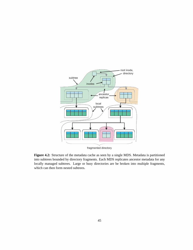
root inode,
directory
inodes
subtree
fragmented directory
ancestor
replicas
local
subtrees
Figure 4.2: Structure of the metadata cache as seen by a single MDS. Metadata is partitionedinto subtrees bounded by directory fragments. Each MDS replicates ancestor metadata for anylocally managed subtrees. Large or busy directories are be broken into multiple fragments,which can then form nested subtrees.
45

is “soft state” in that it is described only by the cluster’s collective in-memorycache (and, by
extension, journal contents). Each MDS is aware only of the authority formetadata present
in its own cache. Clients cache subtree boundaries as they encounter themto efficiently direct
metadata requests.
4.3.2 Metadata Replication
Metadata replication serves two key purposes. First, it allows each node tocache a
connected hierarchy, which is important for maintaining cache consistency. Metadata is also
replicated for availability—both when the cluster is under heavy load and when a subset of
nodes fail.
Ceph imposes fourdistributed cache constraintsthat are critical for failure recovery
and simplify normal cache operations: (1) all cached metadata must be attached to the root
of the hierarchy (i. e. all ancestors must also be cached); (2) any directory fragment bounds
for an authoritative subtree,i. e. the root directory fragments of any child sub-trees, though
not necessary they dentries they contain, must have local replicas; (3)the authority for any
replicated metadata must be known; and (4) all replicas must be known by theauthority.
Constraints (1) and (2) ensure that path resolution can start at any node, and that an
MDS resolving a path will know when traversal reaches a subtree boundary. Replicating an-
cestor metadata further ensures that, for example, the failure ofmds0—which manages the root
directory—will not prevent path traversal on other nodes managing nested subtrees. Similarly,
popular directories are flagged for replication, allowing most read-only requests to be serviced
even if the authoritative MDS has failed.
46

Constraints (2) and (3) ensure that it will be clear to which MDS we should delegate
if path traversal reaches the edge of an authoritative subtree: the bounding directory fragment
replica will indicate the authority for the nested subtree. Note that replicating adirectory frag-
ment does not imply replication of its contents (dentries and inodes)—only thatthe replica will
remain informed of the fragment’s authority. Finally, constraint (4) facilitateslocking when
operations affect replicated metadata, and ensures authoritative metadatacan be expired from
the cache after replicas are destroyed.
4.3.3 Locking
Each piece of replicated metadata is protected by a lock—a simple distributed state
machine that controls whether an MDS can read or modify a given set of fields. Locking is fine-
grained: although each dentry is protected by a single lock (controlling whether that element of
the namespace can be read), each inode has five locks, each controllinga different set of related
fields (e. g. link count and anchor status; file ownership and mode; file size andmtime; directory
fragmentation). Lock acquisition is ordered by〈locktype,ob ject〉 to avoid deadlock.
Each lock’s state machine is constructed to minimize MDS interaction for the ex-
pected usage of the protected fields. Most fields are protected by a simple lock that keeps
replicas consistent and readable by default, but allows an exclusive write lock on the authority
for updates. File size andmtime, on the other hand, are protected by a lock with states cor-
responding to modes of client file access: single client, shared read, or mixed read/write or
shared write. A “scatter” lock regulates themtimefield for directory inodes when fragment(s)
are managed by different MDSs than the inode: concurrent updates are allowed unless the lock
47

is moved to a state that combines values and allowsmtimeto be read.
Ordinarily all update operations are forwarded to the metadata object authority for se-
rialization and journaling. A few operations (link, unlink, andrename) affect multiple metadata
objects that may be managed by different MDS nodes throughslave updates. For example, if
link is creating a hard link in a directory on the current MDS that refers to an inode on a different
MDS, it will issue a slave request to increment the link count. Slaved updatesare applied using
a two-phase commit protocol: once all slaves have journaled a “prepare”event, the coordinating
MDS journals the update (effectively committing the transaction), and slaves journal matching
“committed” events to close the transaction state.
4.3.4 Load Balance
Each MDS monitors the popularity of cached metadata through counters associated
with each inode and directory fragment. Each inode popularity vector includes a read and a
write counter, while directory fragments additionally monitorreaddir operations and the fre-
quency that metadata is fetched from or committed to the object store. In additionto its own
popularity, each directory maintains three additional load vectors that formsummations over
metadata nested deeper within the hierarchy: one for all nested metadata, one for all nested
metadata for which the current node is authoritative, and one for authoritative metadata within
the current subtree only.
When an MDS services client requests, the appropriate counters are incremented on
the affected metadata and its ancestors in order to provide a hierarchical view of metadata
popularity, which is in turn used to inform replication and migration decisions. An exponential
48

decay factor is applied when counters are read, providing a smoothed approximation of recent
popularity.
Nodes in the MDS cluster periodically share their overall load level, as well as the
cumulative popularity of locally managed metadata grouped by the authoritativeMDS of the
immediate ancestor for each subtree. This allows each overloaded node to determine the fraction
of its overall workload to shed to underloaded nodes, while favoring migrations that reunify
child subtrees with their parents. The hierarchical popularity accounting isthen used to select
appropriately sized subtrees to migrate.
While the popularity counters measure the frequency of metadata access, afinal
counter for each directory measures popularityspread. Each directory has a short list of the
clients to last access its contents. The spread counter is incremented only when a new client’s
request is processed. Spread helps inform metadata replication decisions for availability, as
demonstrated in Section 4.5.7.
4.3.5 Subtree Migration
Each subtree migration is a transfer of all cached metadata for the subtree.This
exchange includes non-dirty metadata (that, strictly speaking, is not needed for correctness)
because cache-worthiness is presumably unrelated to which MDS managesit, and the one-time
cost during migration is significantly less expensive than re-fetching evena small subset of the
data from the metadata store.
Migration involves a few initial message exchanges to set up the transfer, and then
a two-phase commit: the “importing” node journals a copy of all imported metadata (Import-
49

Start), the “exporting” node commits the migration by journaling an Export event, and the
importer journals an ImportFinish to close the transaction in its journal. Any “bystander” nodes
who also replicate the root of the subtree are notified before the migration begins and after it
completes, so that any cache expiration messages can be directed at both the old and new subtree
authorities. This is necessary to ensure expirations are reliably delivered in the face of importer
or exporter node failure, to preserve cache invariant (3). (A failureof both nodes is handled
during theresolvephase; see Section 4.4.3.4.)
The relative ease with which subtrees are migrated is made possible by embedded
inodes, which place all metadata within a single hierarchical namespace with a well-defined
partition. Similarly, the use of a shared object store for metadata storage facilitates migration
for arbitrarily large subtrees of the file system, as each migration involves only the transfer of
cachedmetadata.
4.3.6 Directory Fragments
Metadata replication facilitates the distribution of read operations only, while subtrees
are normally partitioned at the granularity of the directory hierarchy. Neither mechanism ad-
dresses load imbalance associated with individual directories that are extremely large or heavily
updated (as in many high performance computing applications [98]). Moreover, our basic ap-
proach to directory metadata storage (each directory’s dentries and inodes written to a single
object) does not scale well to large directories, nor does prefetching theentire directory always
make sense in such a scenario.
In order to address both issues, Ceph extends the directory hierarchyto allow di-
50

2
2
2
4
1100/4
1101/4111/3101/3100/301/200/2
Figure 4.3: Directories are fragmented based on a tree in which each interior node hasa 2n
children, and leaves correspond to individual fragments. Fragments are described by a bit pat-tern and mask, like an IP subnet, partitioning an integer namespace. Dentriesare assigned to aspecific fragment using a hash functions.
rectory contents to be broken into multiple fragments. The one-to-many relationship between
directory inodes and directory fragments is specified by afrag treestructure stored in the in-
ode. An integer namespace is partitioned into one or more fragments based ona tree in which
interior vertices split by powers of two, and the leaves are individual fragments, as illustrated
in Figure 4.3. Each fragment is described by a bit mask (indicating which bits are significant)
and a value for those bits, like an IP network and netmask. Directory entriesare mapped into a
particular directory fragment by hashing the file name and looking up the resulting value in the
frag tree.
Each directory fragment’s metadata are stored in a separate object, allowingextremely
large directories to be stored efficiently.Readdirproceeds in fragment order and returns meta-
data in fragment-sized chunks, preserving prefetching performance for applications that touch
every file in the directory. Because our subtree-based metadata partition isdefined in terms
of directory fragments, load can be finely delegated by migrating fragments between MDS
nodes. Any fragment can be split into 2n sub-fragments if it becomes large or busy. Conversely,
fragments can be rejoined if load decreases or a directory shrinks. There is an I/O cost as-
51

sociated with fragment splits and merges, as both operations involve writing out the resulting
per-directory fragment metadata objects.
4.3.7 Traffic Control
To effectively adapt to a changing workload, the MDS cluster must also cope with
situations where a large number of clients access the same file or directory in the hierarchy at
the same time, even suddenly and without warning. Extremely popular files anddirectories
and sudden “flash crowds” are common in scientific computing workloads [98] (where large
numbers of nodes may be acting in unison) and general purpose workloads where large numbers
of users access similar files due to external events. If tens of thousandsof clients access a single
MDS simultaneously, that node will not be able to handle the request workload efficiently.
The fundamental problem is client knowledge of the metadata partition: if all clients
know where to access any given piece of metadata at any time (based on a well-defined hashing
strategy, for instance) then there is nothing to prevent them from simultaneously accessing the
same item. Similarly, if clients are ignorant of the metadata distribution, then their requests
must be directed randomly and forwarded within the MDS cluster, or pass through some sort of
proxy, in either case requiring an extra network hop for all requests. Ideally, one would like a
combination of the two situations: access to unpopular items to be directed at the authoritative
MDS nodes, and access to popular items to be directed at many or all nodes (each replicating
the popular metadata) to distribute traffic.
Ceph controls how client requests are directed by using clients’ initial ignorance of the
metadata distribution to achieve near-ideal traffic flow for both popular andunpopular metadata.
52

All MDS responses sent to clients include current replication information—that is, which MDS
nodes the client should contact in the future—for the metadata requested and their ancestors,
which are then cached on the client. For unpopular items, the MDS cluster tells clients to
direct future requests only at the authoritative node, while for popular items the client is told
the item is replicated on many or all nodes. Because the popularity metric approximates the
prevalence of an item in all client caches, the MDS cluster can effectivelybound the number of
nodes believing any particular file or subtree of the file hierarchy is locatedin any one place at
all times, thus avoiding potential flash crowds before they can occur while still allowing most
requests for unpopular data to be directed efficiently.
This strategy works for both explored and unexplored portions of the hierarchy. Be-
cause client requests are directed based on the deepest known prefix, any potential flood of
requests will initiate from a set of mutually known (and thus popular) directories—in extreme
cases, the root directory, which is known to all clients and consequently highly replicated.
4.4 Failure Recovery
Robust failure recovery is critical in distributed systems, where a large number of
distinct pieces of hardware increases the likelihood of failure. Although our metadata architec-
ture is based on journaling, a relatively standard mechanism for facilitating failure recovery, a
number of factors complicate recovery. First, journals are large: entriesnear the tail may be
significantly out of date. Second, the migration of metadata between serversintroduces inter-
vals of ambiguous authority that must be resolved during recovery. Third, our distributed cache
53

relies on a large amount of “soft” (non-journaled) state in order to function properly, including
the identity of replicas and lock states. Because journaling such metadata would be exorbitantly
expensive, it must be reliably reconstructed during failure recovery.Finally, open file state is
associated with inodes—independent of the namespace—and shared onlywith clients, who are
not always aware of metadata updates that may have relocated an open file’s position in the
hierarchy.
4.4.1 Journal Structure
Each MDS maintains an independent journal containing a chronological sequence of
atomicevents, each of which typically includes some modified or contextual metadata. Ceph
logically divides the event sequence intosegments, and begins each segment with a special
subtree mapevent that describes which subtrees of the hierarchy the MDS was authoritative for
at that point in time.
Because inodes are embedded within the hierarchy, each journaled update must be ac-
companied by the modified metadata’s ancestors in order to locate the item within thehierarchy.
To avoid duplication of contextual metadata in the journal, ancestors are journaled only up to
the root of the containing subtree, and each ancestor is journaled only once per segment (unless
it is subsequently modified). Between the subtree map and events that follow,each segment
provides the necessary context to correctly interpret all metadata updates it contains.
Each piece of dirty metadata in the MDS cache is placed on a linked list for the
segment it was most recently journaled in. Before old segments are trimmed from the tail of
the journal, any directory fragments still referenced by the segment dirty list are committed.
54

New segments are created shortly after the journal extends onto a new storage object, such
that as segments are trimmed the entire backing objects can be deleted to reclaim disk space.
This allows each MDS to trim its own journal with minimal overhead by simply traversing the
appropriate dirty list, in contrast to the cleaner in log-based file systems.
4.4.2 Failure Detection
Each active MDS sends regular beacon messages to a central monitor responsible for
coordinating cluster membership. If an MDS does not check in for a sufficiently long interval, it
is declared down and the status change is broadcast to surviving nodes. MDS processes who do
not receive timely positive acknowledgement in response to their own beacons commit suicide.
4.4.3 Recovery
Each MDS consists entirely of a running process with a large in-memory cache, uti-
lizing a distributed, shared object storage substrate. MDS failure does not result in data un-
availability in the way that hardware failure in systems utilizing a local hard disk or NVRAM
might. Once an MDS is declared down, a process running on any hardware node can be chosen
to recover in its place.
Recovery is broken into four stages. The contents of the journal are first read into
memory, ambiguous subtree authority and the fate of distributed transactions are resolved, client
sessions are reestablished to restore open file state, and finally the node rejoins the cluster’s
distributed cache.
55

4.4.3.1 Replay
Journalreplaybegins with the first complete segment in the journal. The MDS simply
reads all journal events in chronological order and adds any modified or contextual metadata
to its in-memory cache. This serves to recover any dirty metadata that may not have been
committed before the failure, as well as to prime the new MDS’s cache.
Special note is made of events that indicate distributed transactions. For example, the
MDS maintains a list of ImportStart events that are not followed by a matching ImportFinish,
as indicates an ambiguous subtree import that may or may not have been committedby the
exporting MDS. Similar message pairs reflect anchor table updates or slaveupdate transactions
made on behalf oflink, unlink, or renameoperations coordinated by other nodes.
4.4.3.2 Resolve
During theresolvephase, the fate of ambiguous transactions in the journal is deter-
mined. Each recovering node broadcasts aresolvemessage to all MDSs that includes a list
of locally managed subtrees (described by the root and bound directoryfragment identifiers),
ambiguous subtrees that were mid-import at the time of failure, and any slave updates (see
Section 4.3.3) initiated by the target MDS whose fate is unknown. Any surviving (non-failed)
nodes in the cluster send similar resolve messages to each recovering MDS.
As each resolve is processed, the recovering MDS updates its own cache to reflect
the authority of subtrees explicitly claimed by other nodes. Ambiguous slave updates are cross-
checked against the local list of recently committed transactions, and a replyis generated to
inform the recovering node. Once all resolve messages have been received, ambiguous imports
56

are resolved by simply checking if the subtree was unambiguously claimed by another node. (In
the case of failure during subtree migration, only the importer will be unsure of the result; the
exporter either did or did not write a commit to its journal.) Surviving bystanders also examine
resolve messages to learn interrupted migration outcomes.
Finally, each recovering node trims all non-authoritative metadata from its cache that
is not an ancestor of authoritative metadata (and thus required) or subtree bound. This is nec-
essary because it is impossible to know whether any non-authoritative metadata was updated,
moved, or even deleted at some point after it was mentioned in the local journal. To ensure the
remaining replicated ancestor replicas are correct, all nodes replicating arenamed file or direc-
tory mention the event in their journal. This restores all distributed cache constraints except
(4)—replica identity (see Section 4.3.2).
4.4.3.3 Reconnect and Open File State
Open file state, unlike other soft state, is shared not with other MDSs but withclients
mounting the file system. Each recovering MDS reestablishes prior client sessions and queries
clients for previously issued open file handles, which are necessary to recreate the corresponding
capability and lock state in the MDS cache.
However, file opens are not synchronously journaled by the MDS, bothto avoid the
additional latency, and because most files are opened read-only (reliable atimeupdates are not
deemed a priority). Instead, the MDS periodically writes recently opened inodes to the journal,
and clients describe their capabilities by both inode number and last known filename. If an open
file’s inode was not recovered from the cache, the filename will allow it to belocated within the
57

hierarchy. (Again, mentioning renamed replicas provides key information needed to reliably
interpret paths for non-authoritative inodes.)
4.4.3.4 Rejoin
The final stage of recovery restores distributed cache and lock state. Recovering nodes
send aweak rejoinmessage to each MDS, declaring any metadata replicas that the recipient is
authoritative for, and any recovered file capabilities the sender is not authoritative for.
Surviving nodes (who have lost no state) sendstrong rejoinmessages to recovering
nodes, declaring any replicas that they hold, as well as asserting lock state. Any declared repli-
cas that the recovering node does not already hold in its cache are obtained from the survivor:
an item’s absence in the journal implies it has not been modified and the replica istherefore up
to date.
Recovering nodes use rejoin messages to initialize the lists of known replicas associ-
ated with each piece of metadata, and to choose initial lock states that are compatible with any
surviving nodes. Recovered capabilities listed in weak rejoins that fall within locally managed
subtrees are claimed and managed locally, with new client sessions established as necessary.
Although migrating capability management is not strictly necessary (the other MDS clearly
managed the capability just before the failure), reusing the capability migrationmechanism in
place for subtree migration simplified our implementation. Finally, arejoin ackmessage is sent
to initialize replica locks, and the recovered node becomes active.
58

4.4.4 Discussion
Any “dirty” metadata recovered from the journal will be restored to the in-memory
cache. However, at least some of that metadata will likely have been committed by the prior
MDS instance before it failed. Although version numbers are attached to allmetadata objects
to ensure correctness, some unnecessary I/O may result after recovery.
On the other hand, the use of a large journal provides a recovered node with the
warmest subset of the node’s in-memory cache prior to failure. Consequently, simply killing an
MDS process and restarting it is actually faster than if it were cleanly shut down. This durability
resembles that in the Google File System’s MDS [30].
A limitation of this design (and, partly, my implementation) is that the resolve and
rejoin recovery phases require the participation of all failed nodes. Although in certain cases
this requirement can be relaxed, in general a multi-node failure requires parallel recovery.
4.5 Evaluation
The design of Ceph’s MDS architecture is evaluated in three stages. First,I evaluate
the relatively efficiency of static subtree, dynamic subtree, and hash-based approaches in a
simulation environment to demonstrate the advantages of an dynamic, adaptiveapproach. I
next evaluate the performance of Ceph’s MDS, by analyzing static file system snapshots and
captured file system traces in order to better understand metadata workloads and their impact
on performance. Finally, I measure the performance of the implementation with arange of
micro-benchmarks and capture workloads under normal-use and failurescenarios.
59

4.5.1 Metadata Partitioning
I evaluate the relative performance and scalability of a dynamic subtree-based parti-
tion compared to alternative approaches: namely, a static subtree partition (e. g.a collection of
NFS servers), directory-based hashing (e. g.Lustre), file-based hashing, and Lazy Hybrid [15],
a hybrid hash-based approach proposed by Brandtet al. . This comparative evaluation is per-
formed in an event-driven simulation environment.
Initially, I fix the amount of MDS memory per node and scale the entire system:
file system size, number of MDS servers, and client base. Figure 4.4 shows the performance
degradation of individual MDS nodes for different system sizes under a predominately static
(file system and client) workload. Dynamic and static subtree partitioning showthe best per-
formance, the only difference between the two being that the static strategy does not employ
load balancing to adjust the initial partition. In a real workload environment, astatic partition is
unlikely to be practical as file systems and workloads evolve over time and hierarchies are not
typically as easily partitioned as our workload (a large collection of home directories). The ap-
parent performance penalty for load balancing is due to an unfair distribution of metadata: some
MDS nodes manage a small amount of metadata with extremely high efficiency whileothers
have poor cache performance, resulting in a higher (though unfair) overall cluster throughput.
More significantly, the performance of file and directory hashed distributions degrades more
quickly than subtree based partitions due to inefficiencies analyzed in Section 4.5.1.1.
File hashing and lazy hybrid distributions show significantly lower performance due
to inefficient metadata I/O operations, which involve disk requests to load individual inodes
60

0
500
1000
1500
2000
2500
3000
3500
5 10 15 20 25 30 35 40 45 50
Ave
rage
MD
S th
roug
hput
(op
s/se
c)
MDS cluster size
StaticSubtreeDynamicSubtree
DirHashLazyHybrid
FileHash
Figure 4.4: MDS performance as file system, cluster size, and client base are scaled.
into cache. In contrast, the subtree and directory hashing partitioning strategies exploit the
presence of locality in the workload by embedding inodes and storing entire directories together
on disk to allow efficient lookups and prefetching. The benefits of this approach are best seen
by contrasting the performance of the directory and file hashing strategies, which are otherwise
identical.
Lazy Hybrid performance is interesting because it scales almost linearly due to its
ability to avoid performing most path traversals under the evaluated workload. However, this
ability is predicated on the rarity of modifications to the directory permissions andhierarchy
which must be (lazily, but eventually) propagated to potentially large quantitiesof metadata.
4.5.1.1 Prefix Caching
The performance of metadata partitioning strategies is tightly linked to metadata
cache efficiency. One of the primary factors affecting cache utilization is the need to cache
prefix inodes of ancestor directories for the purposes of path traversal. The overhead associated
61

10
20
30
40
50
60
70
80
5 10 15 20 25 30
Fra
ctio
n of
cac
he c
onsu
med
by
pref
ixes
(%
)
MDS servers
DynamicSubtreeStaticSubtree
DirHashFileHash
Figure 4.5: Percentage of cache devoted to ancestor inodes as the file system, client base andMDS cluster size scales. Hashed distributions devote large portions of theircaches to ancestordirectories. The dynamic subtree partition has slightly more ancestors than thestatic partitiondue to the re-delegation of subtrees nested within the hierarchy.
with caching ancestors for hashed partitions is particularly high because directories are scat-
tered throughout the hierarchy and the prefix directory inodes to locate them must be replicated
widely throughout the cluster. Figure 4.5 shows the percentage of MDS cache associated with
ancestors as file system, client base and cluster size scale (as in Figure 4.4). The utilization for
the static subtree partitioning represents a baseline for the file system simulatedand is related
to the ratio of directories to files, the average branching factor and average file depth. The dy-
namic subtree partition devotes slightly more cache to prefixes to anchor subtrees nested within
the hierarchy that have been re-delegated to other MDS nodes to balanceload.
The consumption of cache memory by ancestor metadata has the effect of decreasing
the cache hit rate and thus overall MDS performance. The extent to whichthis affects perfor-
mance is related to the average depth of directories in the hierarchy; obviously, a mostly flat
namespace is more easily distributed—Lazy Hybrid tries to artificially flatten the namespace
to achieve this effect. Ancestor caching overhead is also greater for smaller cache sizes both
62

0.5
0.55
0.6
0.65
0.7
0.75
0.8
0.85
0.9
0.95
1
0 0.1 0.2 0.3 0.4 0.5 0.6
Cac
he h
it ra
te
Cache size relative to total metadata size
DynamicSubtreeStaticSubtree
DirHashFileHash
LazyHybrid
Figure 4.6: Cache hit rate as a function of cache size (as a fraction of total file systemsize).For smaller caches, inefficient cache utilization due to replicated ancestorsresults in lower hitrates.
because memory is more scarce and because the demand for prefixes forpath traversal is related
to the distribution of requests throughout the file system, not just factors proportional to the size
of the cache. Figure 4.6 shows how cache performance varies with the cache size, expressed
as a fraction of the total size of the file system’s metadata. Note that the convergence of the
hit rates as cache size increases is predicated on the degree of locality in the workload; a more
random distribution of requests will result in a performance similar to smaller cache sizes.
4.5.1.2 Traffic Control
One of the key advantages of a dynamic partitioning strategy is the ability to manage
client ignorance to prevent simultaneous access by tens of thousands ofusers from overwhelm-
ing an individual metadata server. Figure 4.7 shows the number of requests processed over time
by individual nodes in the simulated MDS cluster when 10,000 clients simultaneously request
the same file, a scenario typical of many scientific computing workloads. Requests are directed
63
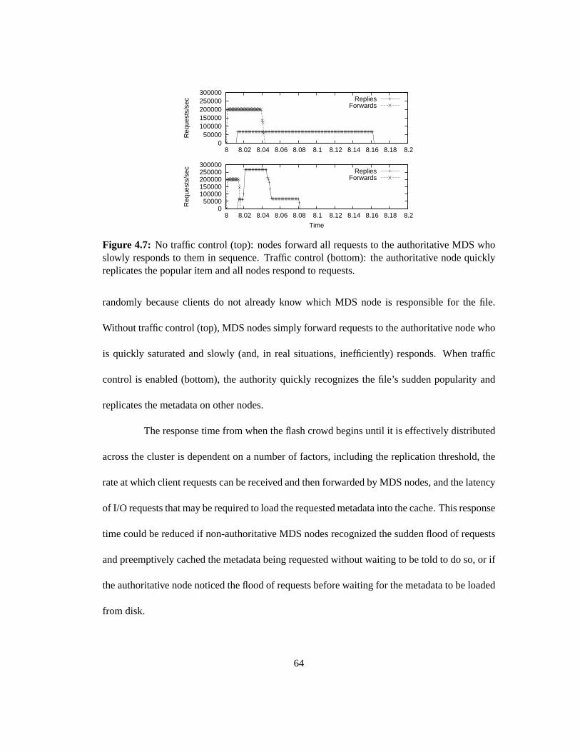
0 50000
100000 150000 200000 250000 300000
8 8.02 8.04 8.06 8.08 8.1 8.12 8.14 8.16 8.18 8.2
Req
uest
s/se
c RepliesForwards
0 50000
100000 150000 200000 250000 300000
8 8.02 8.04 8.06 8.08 8.1 8.12 8.14 8.16 8.18 8.2
Req
uest
s/se
c
Time
RepliesForwards
Figure 4.7: No traffic control (top): nodes forward all requests to the authoritativeMDS whoslowly responds to them in sequence. Traffic control (bottom): the authoritative node quicklyreplicates the popular item and all nodes respond to requests.
randomly because clients do not already know which MDS node is responsible for the file.
Without traffic control (top), MDS nodes simply forward requests to the authoritative node who
is quickly saturated and slowly (and, in real situations, inefficiently) responds. When traffic
control is enabled (bottom), the authority quickly recognizes the file’s sudden popularity and
replicates the metadata on other nodes.
The response time from when the flash crowd begins until it is effectively distributed
across the cluster is dependent on a number of factors, including the replication threshold, the
rate at which client requests can be received and then forwarded by MDS nodes, and the latency
of I/O requests that may be required to load the requested metadata into the cache. This response
time could be reduced if non-authoritative MDS nodes recognized the sudden flood of requests
and preemptively cached the metadata being requested without waiting to be told todo so, or if
the authoritative node noticed the flood of requests before waiting for the metadata to be loaded
from disk.
64

4.5.2 Embedded Inodes
I next consider the performance implications of a metadata storage strategy inwhich
inodes are embedded inside directories. I analyze a range of static file system snapshots, in-
cluding a shared university engineering department file server (soe.*) [74], an aged (10 year)
web and email server file system (destro), a software development server (yakko), and a col-
lection of file systems of varying vintages (0-8 year) for a commercial web (and email) host
(web.*). I measure the performance of a fully functional implementation with a range of micro-
benchmarks and a 2.5 hour web and email workload trace (destro).
This set of experiments primarily reflects general purpose—as opposedto scientific
computing—file system workloads at scale, mainly because paired file systemsnapshot and
workload data from high performance computing systems was not readily available to me. MDS
performance under synthetic workloads based on common scientific computing workload pat-
terns (as described by Wanget al. [98]) is considered in Sections 4.5.4 and 4.5.5.
4.5.2.1 Directory Sizes
I begin by looking at typical directory sizes, and show that the increasedsize of di-
rectories due to embedded inodes has little impact on performance compared tothe overhead
of fetching inodes separately. Figure 4.8 shows the cumulative directory size distributions for
a range of file system snapshots and the Linux kernel source (which I use for certain bench-
marks). More than 95% of directories contain less than 100 entries, and would occupy less
than 20 KB with embedded inodes. This allows for files averaging 20 characters and 160 byte
inodes in place of 64-bit inode numbers—a 6-fold increase in storage. However, for small I/Os,
65

Directory size (entries)1 10 100
Cum
ulat
ive
Fra
ctio
n
0
0.1
0.2
0.3
0.4
0.5
0.6
0.7
0.8
0.9
1
destro
yakko
kernel
web.janky
web.looney
web.randy
web.spacey
soe.csl
soe.fac
soe.grads
soe.etc
Figure 4.8: Cumulative directory size for a variety of static file system snapshots. Manydirec-tories are very small (or even empty), and less than 5% contain more than 100entries.
positioning delays dominate. For example, a random seek followed by a single4 KB read takes
about 13 ms on a commodity 500 GB 7200rpm SATA disk. Reading 20 KB is not significantly
slower, and more than 512 KB (a 2500 file directory) can be read in twice that time. If the seek
is less than 1 MB past the previous read, 256 KB (1300 files) can be readin twice the time of
4 KB.2
4.5.2.2 Metadata Prefetching
The effectiveness of loading entire directories of metadata into cache in a single I/O
is evaluated by measuring the rate at which inodes are accessed for the first time (e. g. due to
a stat or open) relative to the rate directories are loaded. For Linux kernel compilations—the
default and a random configuration—I found that 25-70% of loaded inodes were subsequently
2These measurements were made on a Western Digital WD5000YS-01M under Linux 2.6.21 withO DIRECT.The long seek test measures the time to readn 4 KB blocks of data at a random block-aligned disk offset, averagedover 1000 iterations. The short seek test first reads a random 4 KB block and then measures the time to readn blocksof data located a short distance (between zero and 1 MB) past that.
66
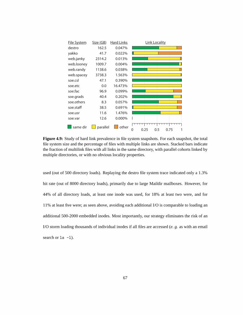
0 0.25 0.5 0.75 1
0.047%
0.022%
0.013%
0.004%
0.038%
1.563%
0.390%
16.473%
0.099%
0.202%
0.057%
0.691%
1.476%
0.000%
same dir parallel other
162.5
41.7
2314.2
1009.7
1138.6
3738.3
47.1
0.0
96.9
40.4
8.3
38.5
11.6
12.6
destro
yakko
web.janky
web.looney
web.randy
web.spacey
soe.csl
soe.etc
soe.fac
soe.grads
soe.others
soe.staff
soe.usr
soe.var
Hard LinksSize (GB)File System Link Locality
Figure 4.9: Study of hard link prevalence in file system snapshots. For each snapshot, the totalfile system size and the percentage of files with multiple links are shown. Stacked bars indicatethe fraction of multilink files with all links in the same directory, with parallel cohortslinked bymultiple directories, or with no obvious locality properties.
used (out of 500 directory loads). Replaying the destro file system traceindicated only a 1.3%
hit rate (out of 8000 directory loads), primarily due to large Maildir mailboxes. However, for
44% of all directory loads, at least one inode was used, for 18% at least two were, and for
11% at least five were; as seen above, avoiding each additional I/O is comparable to loading an
additional 500-2000 embedded inodes. Most importantly, our strategy eliminates the risk of an
I/O storm loading thousands of individual inodes if all files are accessed(e. g.as with an email
search orls -l).
67

4.5.2.3 Multilink File Prevalence and Locality
I analyze a range of file system snapshots to determine the prevalence anddistribution
of hard links. First, in Figure 4.9, we observe that multilinked files are rarelyfound in typical
file systems. When they do occur, all links often appear in the same directory. Moreover, when
multilink files do span directories, they usually have cohorts linked in parallel into the same
pair(s) of directories (as fromcp -lr, which creates a duplicate directory tree that links instead
of copies the original files). Anecdotally, I found that in each of the analyzed file systems with
high rates of hard links, a handful of users were responsible.
4.5.2.4 Anchor Table Performance
When all links for a file occur in the same directory, there is no significant perfor-
mance impact on reads: the remote dentry and inode are loaded into the cachesimultaneously,
avoiding any anchor table query. For link creation, an additional transaction occurs against the
anchor table and existing inode, increasing latency by 150% to 230% (depending on whether
the inode and anchor table are on the same MDS as the new link) in our gigabit ethernet-based
environment.
To measure the impact of the parallel link use-case, I consider the Linux 2.6.22 kernel
source and a duplicate tree with links (created withcp -lr). Starting from a cold cache, a
recursive walk (and stat) of the original tree took 13.4±1.1 seconds, while the copy took 17.9±
.9 seconds—only 34% longer. The limited impact is due to the fact that only one anchor table
query is needed for each directory: once its contents have been loadedinto the cache for the
first hard link, any subsequent parallel links can also be resolved. Consequently, as seen in
68

Figure 4.9, a relatively small fraction of all multilink files require significant interaction with
the anchor table, limiting its impact on performance.
4.5.2.5 Hard Link Lifetime
Multilink files are rarely encountered in part because they are primary used for ma-
nipulating temporary files. The average time interval during which an inode has a link count
greater than one in the destro trace is only a few milliseconds. Ceph’s current implementation
naıvely keeps the entire anchor table in RAM on a designated MDS, such that 1 GB would store
roughly 20 million records, enough for 1–25 billion files (40 TB–1 PB of 40 KB files), given
the rates in Figure 4.9. However, because measured workloads rarely require table queries, and
most updates are short-lived and never read, a more sophisticated table management approach
should scale well.
4.5.3 Journaling
I next consider the performance implications of large journals by analyzingthe effect
of journaling on metadata I/O under a range of workloads.
4.5.3.1 Journal Interval
Large journals optimize metadata I/O by masking multiple metadata updates to the
same objects and combining all dirty data for a directory into a single commit I/O. For example,
for a Linux kernel untar, approximately 30% of journaled entries in each segment are obsolete
by the time they are trimmed (due to themknod, utime, and size/mtimeflush sequence for each
69

file).
More importantly, each directory’s dirty metadata is committed in a single I/O, re-
sulting in significantly fewer directory commits than metadata updates. The extentto which
we are able to group updates into a single commit is related to the time interval covered by the
journal, and the type of directory locality in the workload. For a kernel compilation workload,
the commit rate (relative to the total number of metadata updates), drops from 10% to 3% as the
journal interval grows from 1 to 10 seconds, while for the destro workload it drops to 5% only
after 5 minutes, showing a surprisingly long locality interval. Journal entriesin our workloads
averaged 300-800 bytes each3; a 200 MB journal would contain on the order of 250,000 to
600,000 entries, a two to five minute interval for an MDS doing 2,000 updates per second.
4.5.3.2 Ancestor Metadata
I measure the overhead of journaling contextual ancestor metadata, whichare needed
to place updates in the hierarchy during journal replay. Although naıvely including contextual
metadata in each entry bloats the journal by 100-200% (for untar and compilation workloads),
including any given ancestor just once per 1 MB segment increased the journal size by only
.05%-.2%. That said, journal size is not terribly significant, as sequentialI/O is easy to scale.
A typical MDS would only stream to the journal at a few megabytes per second, an order
of magnitude slower than a single disk, producing a significantly lighter I/O workload than
thousands of updates to hundreds of individual objects.
3Journal entries typically contain multiple inodes, dentries, and other metadata associated with the operation(such as inode number allocation). For example, a file creation journal event includes the inode and dentry for boththe new file and its parent directory (whosemtimechanged). No particular attempt is made to efficiently representthis data, as journal bandwidth—in terms of bytes per second—is relativelylow.
70

Time (seconds)180 210 240 270 300 330 360 390 420
Thr
ough
put (
ops/
sec)
0
5000
10000
15000
20000 mds0 mds1 mds2 mds3
mds4 mds5
Figure 4.10: An MDS cluster adapts to a varying workload. At times 200 and 350 the workloadshifts, as 400 clients begin creating files in private directories and then in a shared directory. Inboth cases load is redistributed, in the latter case after the large (and busy)directory is frag-mented. At time 280 two additional MDSs join the cluster.
4.5.4 Adaptive Distribution
Figure 4.10 demonstrates the MDS cluster’s ability to adapt to varying file and direc-
tory creation workloads. At time 200, the cluster workload shifts as 400 clients begin creating
files in private directories off of the root, all initially managed bymds0. After a few seconds
the workload is redistributed, and at time 270 two additional servers join the cluster. At time
350, the workload shifts again when all clients begin creating files in thesamedirectory. A
few seconds later the (now large) directory is fragmented and load is againredistributed. The
directory is fragmented a second time around time 380, resulting in a dip in throughput as the
new resulting fragments are flushed to disk. Other cluster-wide dips and peaks in throughput are
primarily due to contention in the shared storage pool, underscoring the importance of efficient
71

MDS Cluster Size (nodes)0 16 32 48 64 80 96 112 128
Per
−M
DS
Thr
ough
put (
ops/
sec)
0
1000
2000
3000
4000
5000makedirs
makefiles
openshared
openssh+include
openssh+lib
Figure 4.11: Per-MDS throughput under a variety of workloads and cluster sizes. As the clustergrows to 128 nodes, efficiency drops no more than 50% below perfect linear (horizontal) scalingfor most workloads, allowing vastly improved performance over existing systems.
I/O.
4.5.5 Metadata Scaling
I measure the scalability of the MDS cluster use a 430 node partition of thealc
Linux cluster at Lawrence Livermore National Laboratory (LLNL). Figure 4.11 shows per-
MDS throughput (y) as a function of MDS cluster size (x), such that a horizontal line represents
perfect linear scaling. In themakedirsworkload, each client creates a tree of nested directories
four levels deep, with ten files and subdirectories in each directory. Average MDS throughput
drops from 2000 ops per MDS per second with a small cluster, to about 1000 ops per MDS
per second (50% efficiency) with 128 MDSs (over 100,000 ops/sec total). In the makefiles
workload, each client creates thousands of files in the same directory. When the high write
levels are detected, fragments the shared directory and relaxes the directory’s mtimecoherence
72

to distribute the workload across all MDS nodes. Theopensharedworkload demonstrates read
sharing by having each client repeatedly open and close ten shared files. In theopensshwork-
loads, each client replays a captured file system trace of a compilation in a private directory.
One variant uses a shared/lib for moderate sharing, while the other shares/usr/include,
which is very heavily read. Theopensharedandopenssh+includeworkloads have the heav-
iest read sharing and show the worst scaling behavior, I believe due to poor replica selection
by clients.4 openssh+libscales better than the trivially separablemakedirsbecause it contains
relatively few metadata modifications and little sharing. Although I believe that contention in
the network or threading in the messaging layer further lowered performance for larger MDS
clusters, my limited time with dedicated access to the large cluster prevented a more thorough
investigation.
Figure 4.12 plots latency (y) versus per-MDS throughput (x) for a 4-, 16-, and 64-node
MDS cluster under themakedirsworkload. Larger clusters have imperfect load distributions,
resulting in lower average per-MDS throughput (but, of course, much higher total throughput)
and slightly higher latencies.
Despite imperfect linear scaling, a 128-node MDS cluster running the Cephproto-
type can service more than a quarter million metadata operations per second (128 nodes at
2000 ops/sec). Because metadata transactions are independent of dataI/O and metadata size
is independent of file size, this corresponds to installations with potentially manyhundreds of
petabytes of storage or more, depending on average file size. For example, scientific applica-
tions creating checkpoints on LLNL’s BlueGene/L might involve 64 thousandnodes with two
4Due to limited time with access to the large cluster, this hypothesis was not tested.
73

Per−MDS throughput (ops/sec)0 500 1000 1500 2000
Late
ncy
(ms)
0
10
20
30
40
504 MDSs16 MDSs128 MDSs
Figure 4.12: Average latency versus per-MDS throughput for different cluster sizes (makedirsworkload).
processors each writing to separate files in the same directory (as in themakefilesworkload).
While the current storage system peaks at 6,000 metadata ops/sec and would take minutes to
complete each checkpoint, a 128-node MDS cluster could finish in two seconds. If each file
were only 10 MB (quite small by HPC standards) and OSDs sustain 50 MB/sec, such a cluster
could write 1.25 TB/sec, saturating at least 25,000 OSDs (50,000 with replication). 250 GB
OSDs would put such a system at more than six petabytes. More importantly, dynamic meta-
data distribution allows an MDS cluster (of any size) to reallocate resourcesbased on the current
workload, even when all clients access metadata previously assigned to a single MDS, making
it significantly more versatile and adaptable than any static partitioning strategy.
4.5.6 Failure Recovery
Recovery from multiple MDS failures is demonstrated in Figure 4.13 in a four node
cluster under a file and directory creation workload. At time 400mds3fails (the process is
74
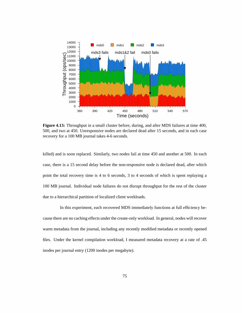
Time (seconds)360 390 420 450 480 510 540 570
Thr
ough
put (
ops/
sec)
0
1000
2000
3000
4000
5000
6000
7000
8000
9000
10000
11000
12000
13000
14000
mds3 fails mds1&2 fail mds0 fails
mds0 mds1 mds2 mds3
Figure 4.13: Throughput in a small cluster before, during, and after MDS failures attime 400,500, and two at 450. Unresponsive nodes are declared dead after 15 seconds, and in each caserecovery for a 100 MB journal takes 4-6 seconds.
killed) and is soon replaced. Similarly, two nodes fail at time 450 and another at 500. In each
case, there is a 15 second delay before the non-responsive node is declared dead, after which
point the total recovery time is 4 to 6 seconds, 3 to 4 seconds of which is spent replaying a
100 MB journal. Individual node failures do not disrupt throughput for the rest of the cluster
due to a hierarchical partition of localized client workloads.
In this experiment, each recovered MDS immediately functions at full efficiency be-
cause there are no caching effects under the create-only workload. In general, nodes will recover
warm metadata from the journal, including any recently modified metadata or recently opened
files. Under the kernel compilation workload, I measured metadata recovery at a rate of .45
inodes per journal entry (1200 inodes per megabyte).
75

4.5.6.1 Recovery Time
Recovery time is governed by a number of factors, although in most cases itis domi-
nated by failure detection and journal replay. I arbitrarily chose 15 seconds for the configurable
delay before non-responsive nodes are declared dead. Although this period dominates down
time in the experiment above, it should be sufficiently long to avoid failing due to transient
network disruptions.
Replay is limited by the rate that the journal is sequentially read from the object
store—only a few seconds for the 100 MB journal above (partly because it is still cached by
the object storage layer), or 20 seconds for a 500 MB journal at 25 MB/second. Large journals
prolong downtime but prime the recovering node’s cache with warm metadata,resulting in
improved performance once they do become available.
The resolve phase involves exchanging small messages with every other MDS, and
is thus dominated by cluster size. For example, a 10-node cluster with a degenerate partition
of thousands of subtrees still resolves in less than 300 ms. In extremely large clusters, such
an exchange may become significant, although such clusters are also typically equipped with
high-performance networks.
The duration of the client reconnect phase is governed by the number ofclients in the
system, but is bounded by a timeout to avoid waiting for unresponsive clients. This timeout
should balance timely recovery versus the risk of stale file handles on laggyclients. I found that
a reconnect over 1.7 million open files among 1000 client processes (spread across 36 hosts)
took ten seconds.
76

Time (seconds)60 75 90 105 120 135 150
Per
−M
DS
Thr
ough
put (
ops/
sec)
0
2000
4000
6000
8000
10000
12000
14000
16000
18000
20000
mds0
mds1
mds2
mds3
Figure 4.14: Per-MDS throughput in a 4-node cluster under a compilation workload with heavyread sharing of/lib. Replication of popular metadata allows progress to continue even whenthe MDS managing the heavily shared directory suffers a failure.
Finally, the rejoin phase is related to the number of MDS nodes and the amount of
metadata replicated by surviving nodes. As with resolve, the exchange ofsmall messages is
fast for all but the largest clusters: for highly separable workloads,rejoin consumes only a few
hundred milliseconds. In a 10-node metadata cluster with extensive metadata replication, a
recovering node spent 6 seconds rejoining: strong rejoin messages, each 5 MB, were processed
from 9 surviving peers, each replicating 30,000 inodes. A final message fetched metadata for
inodes not present in the journal from a survivor.
4.5.7 Availability
Ancestor metadata replication allows nested subtrees to remain available by facilitat-
ing path resolution, as demonstrated in Figure 4.13 by the failure ofmds0(who manages the
77

root directory) at time 500. Adaptive replication of popular directories further limits the im-
pact of a node failure: Figure 4.14 shows per-MDS throughput for a four node cluster under a
workload of 40 clients, each replaying an openssh compilation trace with heavy read sharing of
/lib.5 By replicating that directory’s contents across the cluster (in response toits popularity
and read sharing), the failure of its authoritative MDS does not affect other nodes’ workloads.
Clients direct read-only metadata requests (e. g. stat, openfor read) at replicas when a directory
is flagged for replication, improving availability (as in this experiment) and load distribution for
read/write workloads in which metadata updates must be handled by the authoritative node.
4.6 Future Work
Although the MDS implementation utilizes an object-based storage layer, the ap-
proach is enabled primarily by small inode structures. The extent to which it isapplicable to
other storage architectures—including block-based storage—has not been considered in detail.
A number of auxiliary metadata structures are managed in a naıve fashion. The an-
chor table, for instance, is kept entirely in RAM, as is a table of recently client requests (for
avoiding repetition when recovering from communication or node failure) and a handful of
similar structures. I am investigating alternative data structures and update strategies to serve
the same purpose.
I plan to apply simple heuristics to the management of multilink files such that inodes
are embedded in the directories through which they are most frequently referenced.
5MDS throughputs are higher here than in previous experiments due to a workload consisting primarily of non-update operations.
78

4.7 Experiences
The MDS design was vastly simplified by separating it from the object storagelayer,
avoiding concerns about low-level replication, consistency, and data placement. Similarly, de-
spite my original expectation, the use of a large, lazily trimmed journal in combination with
versioning had a simplifying effect on the implementation of the MDS. Although “dirty” state
has to be associated with the journal segment it was last written to, lazy journal trimming elim-
inates most timing constraints on when in-memory state must be committed to the primary
metadata store.
In my initial design, individual directories could be flagged to distribute metadata
using a hash function across all nodes in the cluster, much like some experimental file sys-
tems [13, 20, 67, 76]. This led to a large number of corner cases, particularly relating to the
subtree partition, and did not mesh well with an architecture in which MDS nodes could be
dynamically added or removed from the cluster. By introducing directory fragments and defin-
ing the subtree partition in terms of that abstraction, Ceph simultaneously achieves both fine-
grained load balancing and addresses storage for very large directories, while adding minimal
complexity to the subtree migration infrastructure.
As my distributed metadata cache design and implementation evolved to accom-
modate arbitrary failure, the importance of setting straightforward invariantsbecame clear—
particularly with respect to the subtree migration infrastructure. Simple rules like “a replica
must know the identity of the authoritative copy” made it clear how to directly address—or
avoid—corner cases as they arose.
79

One of the largest lessons in Ceph was the importance of the MDS load balancer to
overall scalability, and the complexity of choosing what metadata to migrate where and when.
Although in principle the design and goals seem quite simple, the reality of distributing an
evolving workload over a hundred MDSs highlighted additional subtleties. Most notably, MDS
performance has a wide range of performance bounds, including CPU,memory (and cache ef-
ficiency), and network or I/O limitations, any of which may limit performance at any point in
time. Although I experimented with a variety of MDS load functions (including combinations
of metadata popularity, request rates, and queue lengths), in many casessimply using the CPU
load average works as well as anything else. Furthermore, it is difficult toquantitatively cap-
ture the balance between total throughput and fairness; under certain circumstances unbalanced
metadata distributions can increase overall throughput.
4.8 Conclusions
I describe a clustered metadata server that optimizes I/O to the underlying storage
system, adapts its metadata distribution to the current workload, and tolerates arbitrary node
failure. The MDS embeds inodes inside directories for efficient metadata storage and prefetch-
ing, facilitating an efficient and adaptive hierarchical partition of workload. Metadata updates
are first written to large per-MDS journals, which aggregate many updatesto the same directory
into a single commit to the primary metadata structures. This reduces the I/O load onthe under-
lying storage system and improves MDS performance after recovery from a failure by priming
its cache. We adaptively partition workload based a hierarchy defined in terms of directory
80

fragments, facilitating fine-grained load balancing and simple, efficient storage for large direc-
tories. Finally, ancestor and popular metadata is replicated across multiple nodes for improved
availability—both when the cluster is under load, and when a subset of nodes fail.
I consider the merits of a dynamic subtree-based partitioning strategy relative to al-
ternative approaches in a simulation environment. The metadata storage strategy is evaluated
by analyzing a range of static file system snapshots and workloads. I demonstrate the vastly
reduced I/O workload resulting from large journals that exploit workloadlocality, and con-
sider the prevalence of hard links and their impact on the performance of our embedded inode
strategy. Finally, I demonstrate the adaptive workload distribution and failure recovery in the
implementation in terms of performance and metadata availability.
81

Chapter 5
Data Distribution
Object-based storage is an emerging architecture that promises improved manageabil-
ity, scalability, and performance [7]. Unlike conventional block-based hard drives, object-based
storage devices (OSDs) manage disk block allocation internally, exposing an interface that al-
lows others to read and write to variably-sized, named objects. In such a system, each file’s data
is typically striped across a relatively small number of named objects distributedthroughout
the storage cluster. Objects are replicated across multiple devices (or employsome other data
redundancy scheme) in order to protect against data loss in the presence of failures. Object-
based storage systems simplify data layout by replacing large block lists with small object lists
and distributing the low-level block allocation problem. Although this vastly improves scala-
bility by reducing file allocation metadata and complexity, the fundamental task of distributing
data among thousands of storage devices—typically with varying capacities and performance
characteristics—remains.
Most systems simply write new data to underutilized devices. The fundamental prob-
82

lem with this approach is that data is rarely, if ever, moved once it is written. Even a perfect
distribution will become imbalanced when the storage system is expanded, because new disks
either sit empty or contain only new data. Either old or new disks may be busy, depending
on the system workload, but only the rarest of conditions will utilize both equally to take full
advantage of available resources.
A robust solution is to distribute all data in a system randomly among available stor-
age devices. This leads to a probabilistically balanced distribution and uniformly mixes old and
new data together. When new storage is added, a random sample of existingdata is migrated
onto new storage devices to restore balance. This approach has the critical advantage that, on
average, all devices will be similarly loaded, allowing the system to perform well under any
potential workload [84]. Furthermore, in a large storage system, a single large file will be ran-
domly distributed across a large set of available devices, providing a high level of parallelism
and aggregate bandwidth. However, simple hash-based distribution fails tocope with changes
in the number of devices, incurring a massive reshuffling of data. Further, existing randomized
distribution schemes that decluster replication by spreading each disk’s replicas across many
other devices suffer from a high probability of data loss from coincidentdevice failures.
I have developed CRUSH (Controlled Replication Under Scalable Hashing), a pseudo-
random data distribution algorithm that efficiently and robustly distributes object replicas across
a heterogeneous, structured storage cluster. CRUSH is implemented as a deterministic function
that maps an input value—typically an object or object group identifier—to a list of devices on
which to store object replicas. This differs from conventional approaches in that data placement
does not rely on any sort of per-file or per-object directory—CRUSHneeds only a compact, hi-
83

erarchical description of the devices comprising the storage cluster and knowledge of the replica
placement policy. This approach has two key advantages: first, it is completely distributed such
that any party in a large system can independently calculate the location of any object; and sec-
ond, what little metadata is required is mostly static, changing only when devices are added or
removed.
CRUSH is designed to optimally distribute data to utilize available resources, effi-
ciently reorganize data when storage devices are added or removed, and enforce flexible con-
straints on object replica placement that maximize data safety in the presence of coincident or
correlated hardware failures. A wide variety of data safety mechanisms are supported, includ-
ing n-way replication (mirroring), RAID parity schemes or other forms of erasure coding, and
hybrid approaches (e. g. RAID-10). These features make CRUSH ideally suited for manag-
ing object distribution in extremely large (multi-petabyte) storage systems wherescalability,
performance, and reliability are critically important.
5.1 Related Work
Object-based storage has recently garnered significant interest as a mechanism for
improving the scalability of storage systems. A number of research and production file sys-
tems have adopted an object-based approach, including the seminal NASD file system [33], the
Panasas file system [68], Lustre [14], and others [76, 30]. Other block-based distributed file
systems like GPFS [86] and Federated Array of Bricks (FAB) [82] facea similar data distribu-
tion challenge. In these systems a semi-random or heuristic-based approach is used to allocate
84

new data to storage devices with available capacity, but data is rarely relocated to maintain a
balanced distribution over time. More importantly, all of these systems locate datavia some sort
of metadata directory, while CRUSH relies instead on a compact cluster description and deter-
ministic mapping function. This distinction is most significant when writing data, as systems
utilizing CRUSH can calculate any new data’s storage target without consulting a central allo-
cator. The Sorrento [93] storage system’s use of consistent hashing [47] most closely resembles
CRUSH, but lacks support for controlled weighting of devices, a well-balanced distribution of
data, and failure domains for improving data safety.
Although the data migration problem has been studied extensively in the context of
systems with explicit allocation maps [5, 6], such approaches have heavy metadata require-
ments that functional approaches like CRUSH avoid. Choy,et al. [18] describe algorithms for
distributing data over disks which move an optimal number of objects as disks are added, but do
not support weighting, replication, or disk removal. Brinkmann,et al. [17] use hash functions
to distribute data to a heterogeneous but static cluster. Brinkmann later describes an improved
algorithm for placing replicas among a weighted set of disks inO(n) time [16]. SCADDAR [34]
addresses the addition and removal of storage, but only supports a constrained subset of repli-
cation strategies. None of these approaches include CRUSH’s flexibility orfailure domains for
improved reliability.
Brinkmannet al. also describe a problem with many placement algorithms—CRUSH
included—in which data is imperfectly distributed in small clusters with heterogeneous device
weights [16]. In such small clusters, the key properties that CRUSH provides are neither signif-
icant nor required (namely, scalability and support for replica separation).
85

ANU (adaptive, nonuniform randomization) [108] maps data objects and servers onto
a sparse subset of the unit interval, and dynamically adjusts server allocations in response to
observed load. This bears a strong resemblance to CRUSH’s overload mechanism, although
CRUSH requires an initial weight estimate, and Ceph does not implement ANU’s heuristics
for limiting load thrashing. However, like consistent hashing, ANU maps objects to individual
servers with no support for replication, and further lacks CRUSH’s flexible placement rules,
support for failure domains, or a tunable balance between performanceand stability.
CRUSH most closely resembles the RUSH [41] family of algorithms upon which
it is based. RUSH remains the only existing set of algorithms in the literature that utilizes a
mapping function in place of explicit metadata and supports the efficient addition and removal of
weighted devices. Despite these basic properties, a number of issues makeRUSH an insufficient
solution in practice. For example, like Brinkmann’s algorithm [16], RUSHR biases placement
of certain replicas to certain devices, effectively providing a placementsetinstead of an ordered
list, while RUSHP does not support the efficient removal of devices. CRUSH fully generalizes
the useful elements of RUSHP and RUSHT while resolving previously unaddressed reliability
and replication issues, and offering improved performance and flexibility.
5.2 The CRUSH algorithm
The CRUSH algorithm distributes data objects among storage devices according to
a per-device weight value, approximating a uniform probability distribution.The distribution
is controlled by a hierarchicalcluster maprepresenting the available storage resources and
86

composed of the logical elements from which it is built. For example, one might describe
a large installation in terms of rows of server cabinets, cabinets filled with disk shelves, and
shelves filled with storage devices. The data distribution policy is defined in terms ofplacement
rules that specify how many replica targets are chosen from the cluster and what restrictions
are imposed on replica placement. For example, one might specify that three mirrored replicas
are to be placed on devices in different physical cabinets so that they donot share the same
electrical circuit.
Given a single integer input valuex, CRUSH will output an ordered list~Rof n distinct
storage targets. CRUSH utilizes a strong multi-input integer hash function whose inputs include
x, making the mapping completely deterministic and independently calculable using only the
cluster map, placement rules, andx. The distribution is pseudo-random in that there is no
apparent correlation between the resulting output from similar inputs or in theitems stored on
any storage device. I say that CRUSH generates adeclustereddistribution of replicas in that the
set of devices sharing replicas for one item also appears to be independent of all other items.
5.2.1 Hierarchical Cluster Map
The cluster map is composed ofdevicesandbuckets, both of which have numerical
identifiers and weight values associated with them. Buckets can contain any number of devices
or other buckets, allowing them to form interior nodes in a storage hierarchy in which devices
are always at the leaves. Storage devices are assigned weights by the administrator to control
the relative amount of data they are responsible for storing. Although a large system will likely
contain devices with a variety of capacity and performance characteristics, randomized data
87
distributions statistically correlate device utilization with workload, such that device load is on
average proportional to the amount of data stored. This results in a one-dimensional placement
metric, weight, which should be derived from the device’s capabilities. Bucket weights are
defined as the sum of the weights of the items they contain.
Buckets can be composed arbitrarily to construct a hierarchy representing available
storage. For example, one might create a cluster map with “shelf” buckets atthe lowest level to
represent sets of identical devices as they are installed, and then combineshelves into “cabinet”
buckets to group together shelves that are installed in the same rack. Cabinets might be further
grouped into “row” or “room” buckets for a large system. Data is placed in the hierarchy by
recursively selecting nested bucket items via a pseudo-random hash-like function. In contrast
to conventional hashing techniques, in which any change in the number of target bins (devices)
results in a massive reshuffling of bin contents, CRUSH is based on four different bucket types,
each with a different selection algorithm to address data movement resulting from the addition
or removal of devices and overall computational complexity.
5.2.2 Replica Placement
CRUSH is designed to distribute data uniformly among weighted devices to maintain
a statistically balanced utilization of storage and device bandwidth resources. The placement
of replicas on storage devices in the hierarchy can also have a critical effect on data safety.
By reflecting the underlying physical organization of the installation, CRUSHcan model—
and thereby address—potential sources of correlated device failures. Typical sources include
physical proximity, a shared power source, and a shared network. Byencoding this information
88

into the cluster map, CRUSH placement policies can separate object replicas across different
failure domains while still maintaining the desired distribution. For example, to address the
possibility of concurrent failures, it may be desirable to ensure that data replicas are on devices
in different shelves, racks, power supplies, controllers, and/or physical locations.
In order to accommodate the wide variety of scenarios in which CRUSH might be
used, both in terms of data replication strategies and underlying hardware configurations, CRUSH
definesplacement rulesfor each replication strategy or distribution policy employed that allow
the storage system or administrator to specify exactly how object replicas are placed. For ex-
ample, one might have a rule selecting a pair of targets for 2-way mirroring, one for selecting
three targets in two different data centers for 3-way mirroring, one for RAID-4 over six storage
devices, and so on1.
Each rule consists of a sequence of operations applied to the hierarchy ina simple ex-
ecution environment, presented as pseudocode in Algorithm 1. The integerinput to the CRUSH
function,x, is typically an object name or other identifier, such as an identifier for a group of
objects whose replicas will be placed on the same devices. Thetake(a)operation selects an
item (typically a bucket) within the storage hierarchy and assigns it to the vector~i, which serves
as an input to subsequent operations. Theselect(n,t)operation iterates over each elementi ∈~i,
and choosesn distinct items of typet in the subtree rooted at that point. Storage devices have
a known, fixed type, and each bucket in the system has a type field that is used to distinguish
between classes of buckets (e. g. those representing “rows” and those representing “cabinets”).
For eachi ∈~i, theselect(n,t)call iterates over ther ∈ 1, . . . ,n items requested and recursively
1Although a wide variety of data redundancy mechanisms are possible, for simplicity I will refer to the dataobjects being stored asreplicas, without any loss of generality.
89

Algorithm 1 CRUSH placement for objectx
1: procedure TAKE(a) ⊲ Put itema in working vector~i2: ~i ← [a]3: end procedure
4: procedure SELECT(n, t) ⊲ Selectn items of typet5: ~o← /0 ⊲ Our output, initially empty6: for i ∈~i do ⊲ Loop over input~i7: f ← 0 ⊲ No failures yet8: for r ← 1,n do ⊲ Loop overn replicas9: fr ← 0 ⊲ No failures on this replica
10: retry descent← false11: repeat12: b← bucket(i) ⊲ Start descent at bucketi13: retry bucket← false14: repeat15: if “first n” then ⊲ See Section 5.2.2.216: r ′ ← r + f17: else18: r ′ ← r + frn19: end if20: o← b.c(r ′,x) ⊲ See Section 5.2.421: if type(o) 6= t then22: b← bucket(o) ⊲ Continue descent23: retry bucket← true24: else ifo∈~o or failed(o) or overload(o,x) then25: fr ← fr +1, f ← f +126: if o∈~o and fr < 3 then27: retry bucket← true ⊲ Retry collisions locally (see Section 5.2.2.1)28: else29: retry descent← true ⊲ Otherwise retry descent fromi30: end if31: end if32: until ¬retry bucket33: until ¬retry descent34: ~o← [~o,o] ⊲ Add o to output~o35: end for36: end for37: ~i ←~o ⊲ Copy output back into~i38: end procedure
39: procedure EMIT ⊲ Append working vector~i to result40: ~R← [~R,~i]41: end procedure
90

choose(1,row)
choose(3,cabinet)
choose(1,disk)
··················
···············
··················
···············
···············
··················
root
row2
row1 row3 row4
cab24cab21
cab22
cab23
Figure 5.1: A partial view of a four-level cluster map hierarchy consisting of rows, cabinets, andshelves of disks. Bold lines illustrate items selected by eachselectoperation in the placementrule and fictitious mapping described by Table 5.1.
Action Resulting~itake(root) rootselect(1,row) row2select(3,cabinet) cab21 cab23 cab24select(1,disk) disk2107 disk2313 disk2437emit
Table 5.1: A simple rule that distributes three replicas across three cabinets in the same row.
descends through any intermediate buckets, pseudo-randomly selecting anested item in each
bucket using the functionc(r,x) (defined for each kind of bucket in Section 5.2.4), until it finds
an item of the requested typet. The resultingn|~i| distinct items are placed back into the input~i
and either form the input for a subsequentselect(n,t)or are moved into the result vector with an
emitoperation.
As an example, the rule defined in Table 5.1 begins at the root of the hierarchy in
Figure 5.1 and with the firstselect(1,row)chooses a single bucket of type “row” (it selectsrow2).
91

The subsequentselect(3,cabinet)chooses three distinct cabinets nested beneath the previously
selectedrow2 (cab21,cab23,cab24), while the finalselect(1,disk)iterates over the three cabinet
buckets in the input vector and chooses a single disk nested beneath eachof them. The final
result is three disks spread over three cabinets, but all in the same row. This approach thus allows
replicas to be simultaneously separated across and constrained within container types (e. g.
rows, cabinets, shelves), a useful property for both reliability and performance considerations.
Rules consisting of multipletake, emitblocks allow storage targets to be explicitly drawn from
different pools of storage, as might be expected in remote replication scenarios (in which one
replica is stored at a remote site) or tiered installations (e. g. fast, near-line storage and slower,
higher-capacity arrays).
5.2.2.1 Collisions, Failure, and Overload
The select(n,t)operation may traverse many levels of the storage hierarchy in order
to locaten distinct items of the specified typet nested beneath its starting point, a recursive
process partially parameterized byr = 1, . . . ,n, the replica number being chosen. During this
process, CRUSH may reject and reselect items using a modified inputr ′ for three different
reasons: if an item has already been selected in the current set (a collision—theselect(n,t)result
must be distinct), if a device isfailed, or if a device isoverloaded. Failed or overloaded devices
are marked as such in the cluster map, but left in the hierarchy to avoid unnecessary shifting of
data. CRUSH’s selectively diverts a fraction of an overloaded device’s data by pseudo-randomly
rejecting with the probability specified in the cluster map—typically related to its reported over-
utilization. For failed or overloaded devices, CRUSH uniformly redistributesitems across the
92

storage cluster by restarting the recursion at the beginning of theselect(n, t) (see Algorithm 1
line 11). In the case of collisions, an alternater ′ is used first at inner levels of the recursion to
attempt a local search (see Algorithm 1 line 14) and avoid skewing the overall data distribution
away from subtrees where collisions are more probable (e. g. where buckets are smaller than
n).
5.2.2.2 Replica Ranks
Parity and erasure coding schemes have slightly different placement requirements
than replication. In primary copy replication schemes, it is often desirable after a failure for
a previous replica target (that already has a copy of the data) to become the new primary. In
such situations, CRUSH can use the “first n” suitable targets by reselectingusing r ′ = r + f ,
where f is the number of failed placement attempts by the currentselect(n,t)(see Algorithm 1
line 16). With parity and erasure coding schemes, however, the rank or position of a storage
device in the CRUSH output is critical because each target stores different bits of the data object.
In particular, if a storage device fails, it should be replaced in CRUSH’s output list~R in place,
such that other devices in the list retain the same rank (i. e. position in~R, see Figure 5.2). In such
cases, CRUSH reselects usingr ′ = r + frn, where fr is the number of failed attempts onr, thus
defining a sequence of candidates for each replica rank that are probabilistically independent of
others’ failures. In contrast, RUSH has no special handling of failed devices; like other existing
hashing distribution functions, it implicitly assumes the use of a “first n” approach to skip over
failed devices in the result, making it unwieldy for parity schemes.
93

a b c d e f
a c d e f g
a b c d e f
a h c d e f
g h
g i j k l
h
…
g i j k lh
… … … … … …
… … … … … …
1 2 3 4 5 6
1 2 3 4 5 6
1 2 3 4 5 6
1 2 3 4 5 6
r’ = r + f r’ = r + frn
Figure 5.2: Reselection behavior ofselect(6,disk)when devicer = 2 (b) is rejected, where theboxes contain the CRUSH output~R of n = 6 devices numbered by rank. The left shows the“first n” approach in which device ranks of existing devices (c,d,e, f ) may shift. On the right,each rank has a probabilistically independent sequence of potential targets; herefr = 1, andr ′ = r + frn = 8 (deviceh).
5.2.2.3 Force-feeding
In a variety of environments it is desirable to specify the placement of the first replica.
For example, in distributed computing environments in which each server performs both com-
putation and storage tasks, network utilization can be significantly lowered if the first replica is
stored locally. To enable such behavior, CRUSH allows you to “force-feed” a specific first de-
vice to the placement algorithm, while still maintaining all other placement constraintsimposed
by the placement rule. (Note that although force feeding is relatively straightforward, it is not
included in Algorithm 1.)
This is accomplished by consulting the device hierarchy that the placement rule is
utilizing (i. e. that nested beneath the initialtake), and inferring the choices that would be made
by eachselectto ultimately choose the force fed item. Each select initially chooses the inferred
or force fed item, and then proceeds pseudo-randomly for any additional results, producing a
94

distinct result list as before. This ensures that constraints imposed by theplacement rule (e. g.
separation of replicas within the hierarchy) are maintained, despite an explicit choice of the
initial result.
Force feeding requires that each device only occurs once in the givensubtree of the
hierarchy in order to unambiguously determine the parent for each node,although the rest of
the CRUSH algorithm has no such restriction. This would only be significant for unusual hier-
archies not considered here.
5.2.3 Map Changes and Data Movement
A critical element of data distribution in a large file system is the response to the
addition or removal of storage resources. CRUSH maintains a uniform distribution of data
and workload at all times in order to avoid load asymmetries and the related underutilization of
available resources. When an individual device fails, CRUSH flags the device but leaves it in the
hierarchy, where it will be rejected and its contents uniformly redistributed by the placement
algorithm (see Section 5.2.2.1). Such cluster map changes result in an optimal(minimum)
fraction,wf ailed/W (whereW is the total weight of all devices), of total data to be remapped to
new storage targets because only data on the failed device is moved.
The situation is more complex when the cluster hierarchy is modified, as with the
addition or removal of storage resources. The CRUSH mapping process, which uses the cluster
map as a weighted hierarchical decision tree, can result in additional data movement beyond
the theoretical optimum of∆wW . At each level of the hierarchy, when a shift in relative subtree
weights alters the distribution, some data objects must move from from subtreeswith decreased
95

1X2
1 1
2
4
1 1
2
1 1
2
1 1
Added item
Affected weights78
34
X
X
Figure 5.3: Data movement in a binary hierarchy due to a node addition and the subsequentweight changes.
weight to those with increased weight. Because the pseudo-random placement decision at each
node in the hierarchy is statistically independent, data moving into a subtree is uniformly redis-
tributed beneath that point, and does not necessarily get remapped to the leaf item ultimately
responsible for the weight change. Only at subsequent (deeper) levels of the placement process
does (often different) data get shifted to maintain the correct overall relative distributions. This
general effect is illustrated in the case of a binary hierarchy in Figure 5.3.
The amount of data movement in a hierarchy has a lower bound of∆wW , the fraction of
data that would reside on a newly added device with weight∆w. Data movement increases with
the heighth of the hierarchy, with a conservative asymptotic upper bound ofh∆wW . The amount
of movement approaches this upper bound when∆w is small relative toW, because data objects
moving into a subtree at each step of the recursion have a very low probability of being mapped
to an item with a small relative weight.
5.2.4 Bucket Types
Generally speaking, CRUSH is designed to reconcile two competing goals: efficiency
and scalability of the mapping algorithm, and minimal data migration to restore a balanced dis-
96

Action Uniform List Tree StrawSpeed O(1) O(n) O(log n) O(n)Additions poor optimal good optimalRemovals poor poor good optimal
Table 5.2: Summary of mapping speed and data reorganization efficiency of different buckettypes when items are added to or removed from a bucket.
tribution when the cluster changes due to the addition or removal of devices.To this end,
CRUSH defines four different kinds of buckets to represent internal(non-leaf) nodes in the
cluster hierarchy:uniform buckets, list buckets, tree buckets, andstraw buckets. Each bucket
type is based on a different internal data structure and utilizes a different function c(r,x) for
pseudo-randomly choosing nested items during the replica placement process, representing a
different tradeoff between computation and reorganization efficiency.Uniform buckets are re-
stricted in that they must contain items that are all of the same weight (much like a conventional
hash-based distribution function), while the other bucket types can contain a mix of items with
any combination of weights. These differences are summarized in Table 5.2.
5.2.4.1 Uniform Buckets
Devices are rarely added individually in a large system. Instead, new storage is typ-
ically deployed in blocks of identical devices, often as an additional shelf ina server rack or
perhaps an entire cabinet. Devices reaching their end of life are often similarly decommissioned
as a set (individual failures aside), making it natural to treat them as a unit. CRUSH uniform
buckets are used to represent an identical set of devices in such circumstances. The key ad-
vantage in doing so is performance related: CRUSH can map replicas into uniform buckets in
97

constant time. In cases where the uniformity restrictions are not appropriate, other bucket types
can be used.
Given a CRUSH input value ofx and a replica numberr, we choose an item from
a uniform bucket of sizem using the functionc(r,x) = (hash(x) + rp) modm, wherep is a
randomly (but deterministically) chosen prime number greater thanm. For anyr ≤ m we can
show that we will always select a distinct item using a few simple number theorylemmas.2 For
r > m this guarantee no longer holds, meaning two different replicasr with the same inputx
may resolve to the same item. In practice, this means nothing more than a non-zeroprobability
of collisions and subsequent backtracking by the placement algorithm (see Section 5.2.2.1).
If the size of a uniform bucket changes, there is a complete reshuffling of data between
devices, much like conventional hash-based distribution strategies.
5.2.4.2 List Buckets
List buckets structure their contents as a linked list, and can contain items with arbi-
trary weights. To place a replica, CRUSH begins at the head of the list with themost recently
added item and compares its weight to the sum of all remaining items’ weights. Depending on
the value of hash(x, r, item), either the current item is chosen with the appropriate probability, or
the process continues recursively down the list. This approach, derived from RUSHP , recasts
the placement question into that of “most recently added item, or older items?” This is a natural
and intuitive choice for an expanding cluster: either an object is relocatedto the newest device
2The Prime Number Theorem for Arithmetic Progressions [36] can be used to further show that this function willdistribute replicas of objectx in mφ(m) different arrangements, and that each arrangement is equally likely.φ(·) isthe Euler Totient function.
98

with some appropriate probability, or it remains on the older devices as before. The result is
optimal data migration when items are added to the bucket. Items removed from the middle or
tail of the list, however, can result in a significant amount of unnecessary movement, making
list buckets most suitable for circumstances in which they never (or very rarely) shrink.
The RUSHP algorithm is approximately equivalent to a two-level CRUSH hierarchy
consisting of a single list bucket containing many uniform buckets. Its fixedcluster represen-
tation precludes the use for placement rules or CRUSH failure domains for controlling data
placement for enhanced reliability.
5.2.4.3 Tree Buckets
Like any linked list data structure, list buckets are efficient for small sets of items but
may not be appropriate for large sets, where theirO(n) running time may be excessive. Tree
buckets, derived from RUSHT , address this problem by storing their items in a binary tree. This
reduces the placement time toO(logn), making them suitable for managing much larger sets of
devices or nested buckets. RUSHT is equivalent to a two-level CRUSH hierarchy consisting of
a single tree bucket containing many uniform buckets.
Tree buckets are structured as a weighted binary search tree with items at the leaves.
Each interior node knows the total weight of its left and right subtrees andis labeled according
to a fixed strategy (described below). In order to select an item within a bucket, CRUSH starts
at the root of the tree and calculates the hash of the input keyx, replica numberr, the bucket
identifier, and the label at the current tree node (initially the root). The result is compared to
the weight ratio of the left and right subtrees to decide which child node to visit next. This
99

1 11
10
100
1000
101 111
110
1001 1011
1010
1100
1111
1110
Figure 5.4: Node labeling strategy used for the binary tree comprising each tree bucket.
process is repeated until a leaf node is reached, at which point the associated item in the bucket
is chosen. Only logn hashes and node comparisons are needed to locate an item.
The bucket’s binary tree nodes are labeled with binary values using a simple, fixed
strategy designed to avoid label changes when the tree grows or shrinks. The leftmost leaf in
the tree is always labeled “1.” Each time the tree is expanded, the old root becomes the new
root’s left child, and the new root node is labeled with the old root’s label shifted one bit to
the left (1, 10, 100, etc.). The labels for the right side of the tree mirror those on the left side
except with a “1” prepended to each value. A labeled binary tree with six leaves is shown in
Figure 5.4. This strategy ensures that as new items are added to (or removed from) the bucket
and the tree grows (or shrinks), the path taken through the binary tree for any existing leaf
item only changes by adding (or removing) additional nodes at the root, atthe beginning of the
placement decision tree. Once an object is placed in a particular subtree, itsfinal mapping will
depend only on the weights and node labels within that subtree and will not change as long
as that subtree’s items remain fixed. Although the hierarchical decision treeintroduces some
additional data migration between nested items, this strategy keeps movement to a reasonable
level, while offering efficient mapping even for very large buckets.
100

5.2.4.4 Straw Buckets
List and tree buckets are structured such that a limited number of hash valuesneed to
be calculated and compared to weights in order to select a bucket item. In doing so, they divide
and conquer in a way that either gives certain items precedence (e. g. those at the beginning
of a list) or obviates the need to consider entire subtrees of items at all. That improves the
performance of the replica placement process, but can also introduce suboptimal reorganization
behavior when the contents of a bucket change due an addition, removal,or re-weighting of an
item.
The straw bucket type allows all items to fairly “compete” against each other for
replica placement through a process analogous to a draw of straws. To place a replica, a straw
of random length is drawn for each item in the bucket. The item with the longeststraw wins.
The length of each straw is initially a value in a fixed range, based on a hash of the CRUSH input
x, replica numberr, and bucket itemi. Each straw length is scaled by a factorf (wi) based on
the item’s weight so that heavily weighted items are more likely to win the draw,i. e. c(r,x) =
maxi ( f (wi)hash(x, r, i)). Although this process is almost twice as slow (on average) than a list
bucket and even slower than a tree bucket (which scales logarithmically),straw buckets result
in optimal data movement between nested items when modified.
The scaling factorf (wi) for each bucket item is precalculated when the bucket is first
created or modified, using the iterative procedure in Algorithm 23. Although the pseudocode is
included here for completeness, its derivation was based on a combination of geometric analysis
3Note that the first portion of the pseudocode is simply creating a sorted mapping reverseby weight using aninsertion sort.
101

and trial and error, and is neither concise nor elegant (I would not be surprised to learn that there
is an equivalent and trivial closed form). The basic intuition is that items with identical weights
will have the same straw scaling value. We sort by weight, and start by giving the least-weighted
items a straw multiplierf (wi) of one. As each successively larger item weight group is “added,”
its straw multiplerf (wi) is chosen based on the desired probabilitypbelow of choosing a shorter
straw versus the next longer straw, where we consider that items with larger straw multipliers
may still result in shorter straw lengths. That is,wbelow andwnext are a product item weight and
the number of items with equal or larger weights, andpbelow= wbelowwbelow+wnext
.
5.2.4.5 Bucket Discussion
The choice of bucket type can be guided based on expected cluster growth patterns
to trade mapping function computation for data movement efficiency where it is appropriate to
do so. When buckets are expected to be fixed (e. g.a shelf of identical disks), uniform buckets
are fastest. If a bucket is only expected to expand, list buckets provideoptimal data movement
when new items are added at the head of the list. This allows CRUSH to divert exactly as much
data to the new device as is appropriate, without any shuffle between otherbucket items. The
downside isO(n) mapping speed and extra data movement when older items are removed or
reweighted. In circumstances where removal is expected and reorganization efficiency is critical
(e. g.near the root of the storage hierarchy), straw buckets provide optimal migration behavior
between subtrees. Tree buckets are an all around compromise, providing excellent performance
and decent reorganization efficiency.
102
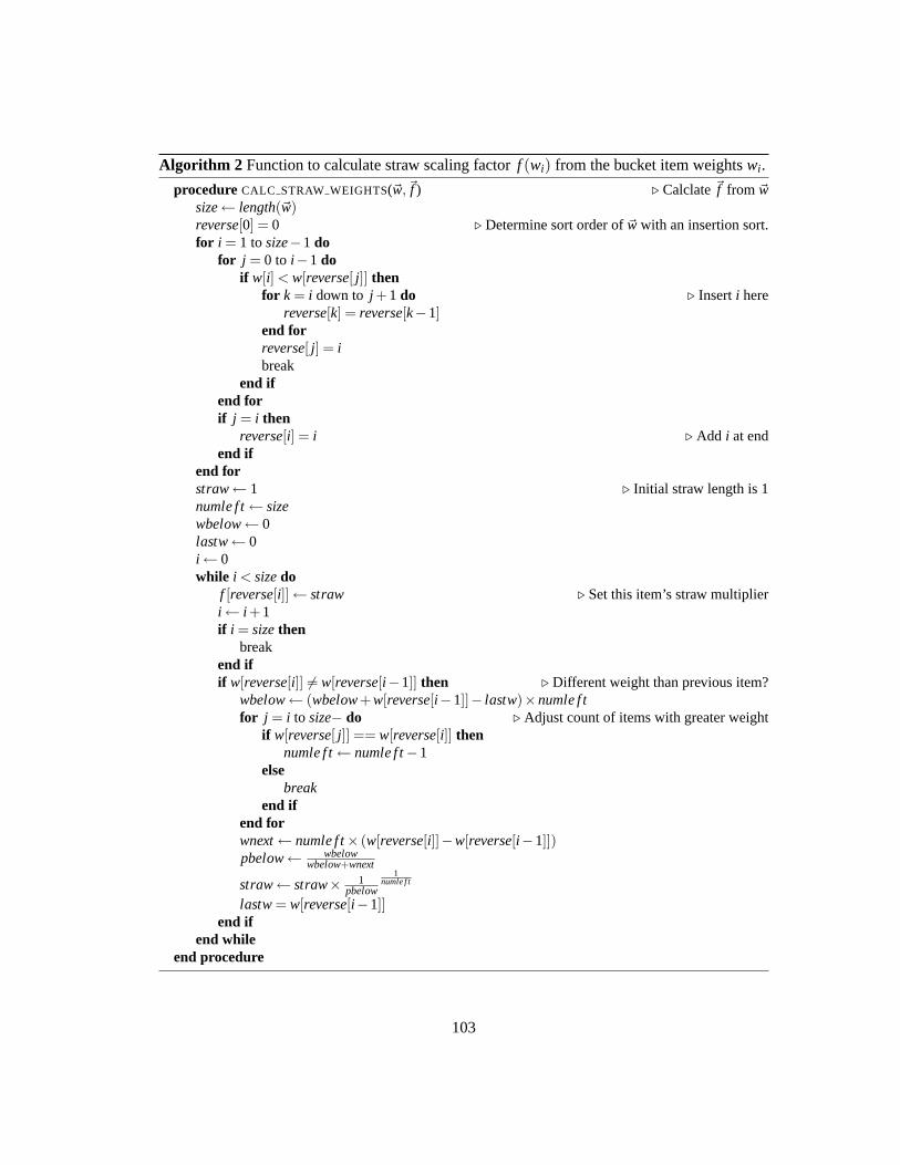
Algorithm 2 Function to calculate straw scaling factorf (wi) from the bucket item weightswi .
procedure CALC STRAW WEIGHTS(~w, ~f ) ⊲ Calclate~f from ~wsize← length(~w)reverse[0] = 0 ⊲ Determine sort order of~w with an insertion sort.for i = 1 tosize−1 do
for j = 0 to i −1 doif w[i] < w[reverse[ j]] then
for k = i down to j +1 do ⊲ Inserti herereverse[k] = reverse[k−1]
end forreverse[ j] = ibreak
end ifend forif j = i then
reverse[i] = i ⊲ Add i at endend if
end forstraw← 1 ⊲ Initial straw length is 1numle f t← sizewbelow← 0lastw← 0i ← 0while i < sizedo
f [reverse[i]] ← straw ⊲ Set this item’s straw multiplieri ← i +1if i = sizethen
breakend ifif w[reverse[i]] 6= w[reverse[i −1]] then ⊲ Different weight than previous item?
wbelow← (wbelow+w[reverse[i −1]]− lastw)×numle f tfor j = i to size− do ⊲ Adjust count of items with greater weight
if w[reverse[ j]] == w[reverse[i]] thennumle f t← numle f t−1
elsebreak
end ifend forwnext← numle f t× (w[reverse[i]]−w[reverse[i −1]])pbelow← wbelow
wbelow+wnext
straw← straw× 1pbelow
1numle f t
lastw= w[reverse[i −1]]end if
end whileend procedure
103

5.3 Evaluation
CRUSH is based on a wide variety of design goals including a balanced, weighted
distribution among heterogeneous storage devices, minimal data movement dueto the addition
or removal of storage (including individual disk failures), improved system reliability through
the separation of replicas across failure domains, and a flexible cluster description and rule sys-
tem for describing available storage and distributing data. I evaluate each of these behaviors
under expected CRUSH configurations relative to RUSHP - and RUSHT -style clusters by sim-
ulating the allocation of objects to devices and examining the resulting distribution.RUSHP
and RUSHT are generalized by a two-level CRUSH hierarchy with a single list or tree bucket
(respectively) containing many uniform buckets. Although RUSH’s fixedcluster representation
precludes the use of placement rules or the separation of replicas acrossfailure domains (which
CRUSH uses to improve data safety), I consider its performance and data migration behavior.
5.3.1 Data Distribution
CRUSH’s data distribution should appear random—uncorrelated to object identifiers
x or storage targets—and result in a balanced distribution across devices with equal weight. I
empirically measured the distribution of objects across devices contained in a variety of bucket
types and compared the variance in device utilization to the binomial probability distribution,
the theoretical behavior I would expect from a perfectly uniform random process. When dis-
tributing n objects with probabilitypi = wiW of placing each object on a given devicei, the
expected device utilization predicted by the corresponding binomialb(n, p) is µ = np with a
104

standard deviation ofσ =√
np(1− p). In a large system with many devices, we can approxi-
mate 1− p≃ 1 such that the standard deviation isσ ≃√µ—that is, utilizations are most even
when the number of data objects is large.4 As expected, I found that the CRUSH distribution
consistently matched the mean and variance of a binomial for both homogeneous clusters and
clusters with mixed device weights.
5.3.1.1 Overload Protection
Although CRUSH achieves good balancing (a low variance in device utilization) for
large numbers of objects, as in any stochastic process this translates into a non-zero probability
that the allocation on any particular device will be significantly larger than the mean. Unlike
existing probabilistic mapping algorithms (including RUSH ), CRUSH includes a per-device
overload correction mechanism that can redistribute any fraction of a device’s data. This can be
used to scale back a device’s allocation proportional to its over-utilization when it is in danger
of overfilling, selectively “leveling off” overfilled devices. When distributing data over a 1000-
device cluster at 99% capacity, I found that CRUSH mapping execution times increase by less
than 20% despite overload adjustments on 47% of the devices, and that the variance decreased
by a factor of four (as expected).
5.3.1.2 Variance and Partial Failure
Prior research [84] has shown that randomized data distribution offersreal-world sys-
tem performance comparable to (but slightly slower than) that of careful data striping. In my
4The binomial distribution is approximately Gaussian when there are many objects (i. e. whenn is large).
105

Devices DevicesUsage Overfilled Adjusted Time σ
50% 0 0 1.000 .10070% .7% 1.9% 1.003 .09875% 1.6% 3.8% 1.016 .09580% 2.9% 6.4% 1.022 .09385% 7.7% 12.9% 1.035 .08190% 15.2% 22.1% 1.040 .06695% 28.6% 35.4% 1.092 .04197% 38.3% 41.4% 1.161 .02999% 44.5% 46.3% 1.163 .025
Table 5.3: As the total utilization of available storage approaches capacity, the number of de-vices that would otherwise overfill and that require adjustment increases. CRUSH computationincreases slightly while decreasing variance.
own performance tests of CRUSH in the context of Ceph [100], I found that randomizing ob-
ject placement resulted in an approximately 5% penalty in write performance due to variance
in the OSD workloads, related in turn to the level of variation in OSD utilizations. In practice,
however, such variance is primarily only relevant for homogeneous workloads (usually writes)
where a careful striping strategy is effective. More often, workloadsare mixed and already ap-
pear random when they reach the disk (or at least uncorrelated to on-disk layout), resulting in
a similar variance in device workloads and performance (despite carefullayout), and similarly
reduced aggregate throughput. I find that CRUSH’s lack of metadata androbust distribution in
the face of any potential workload far outweigh the small performance penalty under a small
set of workloads.
This analysis assumes that device capabilities are more or less static over time. Ex-
perience with real systems suggests, however, that performance in distributed storage systems
is often dragged down by a small number of slow, overloaded, fragmented, or otherwise poorly
106

performing devices. Traditional, explicit allocation schemes can manually avoid such prob-
lem devices, while hash-like distribution functions typically cannot. CRUSH allows degenerate
devices to be treated as a “partial failure” using the existing overload correction mechanism, di-
verting an appropriate amount of data and workload to avoiding such performance bottlenecks
and correct workload imbalance over time.
Fine-grained load balancing by the storage system can further mitigate device work-
load variance by distributing the read workload over data replicas, as demonstrated by the D-
SPTF algorithm [62]; such approaches, although complementary, fall outside the scope of the
CRUSH mapping function and this paper.
5.3.2 Reorganization and Data Movement
I evaluate the data movement caused by the addition or removal of storage when using
both CRUSH and RUSH on a cluster of 7290 devices. The CRUSH clusters are four levels deep:
nine rows of nine cabinets of nine shelves of ten storage devices, for a total of 7290 devices.
RUSHT and RUSHP are equivalent to a two-level CRUSH map consisting of a single tree
or list bucket (respectively) containing 729 uniform buckets with 10 devices each. The results
are compared to the theoretically optimal amount of movementmoptimal =∆wW , where∆w is
the combined weight of the storage devices added or removed andW is the total weight of the
system. Doubling system capacity, for instance, would require exactly halfof the existing data
to move to new devices under an optimal reorganization.
Figure 5.5 shows the relative reorganization efficiency in terms of themovement factor
mactual/moptimal, where 1 represents an optimal number of objects moved and larger valuesmean
107

Mov
emen
t Fac
tor
0
1
2
3
4
5
6
OSDs added or removed10 30 90 270 810 2430 7290
CRUSH, tree bucket
CRUSH, list bucket addition
CRUSH, list bucket removal
CRUSH, straw bucket
RUSH_T
RUSH_P addition
RUSH_P removal
Figure 5.5: Efficiency of reorganization after adding or removing storage devices two levelsdeep into a four level, 7290 device CRUSH cluster hierarchy, versus RUSHP and RUSHT . 1is optimal.
additional movement. TheX axis is the number of OSDs added or removed and theY axis is
the movement factor plotted on a log scale. In all cases, larger weight changes (relative to
the total system) result in a more efficient reorganization. RUSHP (a single, large list bucket)
dominated the extremes, with the least movement (optimal) for additions and most movement
for removals (at a heavy performance penalty, see Section 5.3.3 below).A CRUSH multi-level
hierarchy of list (for additions only) or straw buckets had the next leastmovement. CRUSH
with tree buckets was slightly less efficient, but did almost 25% better than plain RUSHT (due
to the slightly imbalanced 9-item binary trees in each tree bucket). Removals from a CRUSH
hierarchy built with list buckets did poorly, as expected (see Section 5.2.3).
Figure 5.6 shows the reorganization efficiency of different bucket types (in isolation)
when nested items are added or removed. The movement factor in a modified tree bucket is
bounded by logn, the depth of its binary tree. Adding items to straw and list buckets is approx-
imately optimal. Uniform bucket modifications result in a total reshuffle of data.Modifications
108
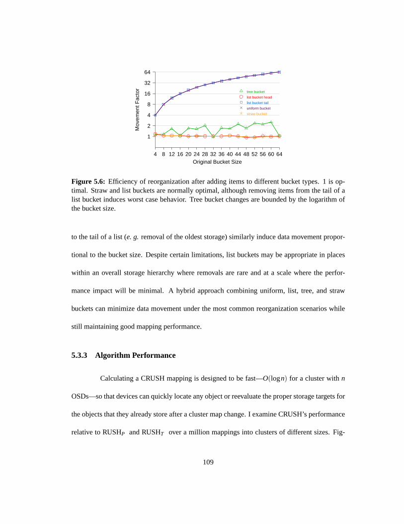
Mov
emen
t Fac
tor
1
2
4
8
16
32
64
Original Bucket Size4 8 12 16 20 24 28 32 36 40 44 48 52 56 60 64
tree bucket
list bucket head
list bucket tail
uniform bucket
straw bucket
Figure 5.6: Efficiency of reorganization after adding items to different bucket types. 1 is op-timal. Straw and list buckets are normally optimal, although removing items from the tailof alist bucket induces worst case behavior. Tree bucket changes arebounded by the logarithm ofthe bucket size.
to the tail of a list (e. g. removal of the oldest storage) similarly induce data movement propor-
tional to the bucket size. Despite certain limitations, list buckets may be appropriate in places
within an overall storage hierarchy where removals are rare and at a scale where the perfor-
mance impact will be minimal. A hybrid approach combining uniform, list, tree, and straw
buckets can minimize data movement under the most common reorganization scenarios while
still maintaining good mapping performance.
5.3.3 Algorithm Performance
Calculating a CRUSH mapping is designed to be fast—O(logn) for a cluster withn
OSDs—so that devices can quickly locate any object or reevaluate the proper storage targets for
the objects that they already store after a cluster map change. I examine CRUSH’s performance
relative to RUSHP and RUSHT over a million mappings into clusters of different sizes. Fig-
109

Tim
e (m
icro
seco
nds)
0
5
10
15
20
25
30
Cluster Size (OSDs)64 512 4096 32768
CRUSH, tree bucket
CRUSH, list bucket
CRUSH, straw bucket
RUSH_T
RUSH_P
Figure 5.7: CRUSH and RUSHT computation times scale logarithmically relative to hierarchysize, while RUSHP scales linearly.
ure 5.7 shows the average time (in microseconds) to map a set of replicas into aCRUSH cluster
composed entirely of 8-item tree and uniform buckets (the depth of the hierarchy is varied) ver-
sus RUSH ’s fixed two-level hierarchy. TheX axis is the number of devices in the system, and is
plotted on a log scale such that it corresponds to the depth of the storage hierarchy. CRUSH per-
formance is logarithmic with respect to the number of devices. RUSHT edges out CRUSH with
tree buckets due to slightly simpler code complexity, followed closely by list and straw buckets.
RUSHP scales linearly in this test (taking more than 25 times longer than CRUSH for 32768
devices), although in practical situations where the size of newly deployeddisks increases ex-
ponentially over time one can expect slightly improved sub-linear scaling [41]. These tests were
conducted with a 2.8 GHz Pentium 4, with overall mapping times in the tens of microseconds.
The efficiency of CRUSH depends upon the depth of the storage hierarchy and on the
types of buckets from which it is built. Figure 5.8 compares the time (Y) required forc(r,x) to
select a single replica from each bucket type as a function of the size of the bucket (X). At a
110

Tim
e (m
icro
seco
nds)
0123456789
10
Bucket Size (items)0 5 10 15 20 25 30 35 40
uniform O(1)
tree O(log n)
list O(n)
straw O(n)
Figure 5.8: Low-level speed of mapping replicas into individual CRUSH buckets versus bucketsize. Uniform buckets take constant time, tree buckets take logarithmic time, andlist and strawbuckets take linear time.
high level, CRUSH scales asO(logn)—linearly with the hierarchy depth—provided individual
buckets that may beO(n) (list and straw buckets scale linearly) do not exceed a fixed maximum
size. When and where individual bucket types should be used depends on the expected number
of additions, removals, or re-weightings. List buckets offer a slight performance advantage over
straw buckets, although when removals are possible one can expect excessive data shuffling.
Tree buckets are a good choice for very large or commonly modified buckets, with decent
computation and reorganization costs.
Central to CRUSH’s performance—both the execution time and the quality of the
results—is the integer hash function used. Pseudo-random values are calculated using a mul-
tiple input integer hash function based on Jenkin’s 32-bit hashmix [45]. In its present form,
approximately 45% of the time spent in the CRUSH mapping function is spent hashing val-
ues, making the hash key to both overall speed and distribution quality and a ripe target for
optimization.
111

5.3.3.1 Negligent Aging
CRUSH leaves failed devices in place in the storage hierarchy both because failure
is typically a temporary condition (failed disks are usually replaced) and because it avoids in-
efficient data reorganization. If a storage system ages in neglect, the number of devices that
are failed but not replaced may become significant. Although CRUSH will redistribute data
to non-failed devices, it does so at a small performance penalty due to a higher probability of
backtracking in the placement algorithm. I evaluated the mapping speed for a 1,000 device
cluster while varying the percentage of devices marked as failed. For the relatively extreme
failure scenario in which half of all devices are dead, the mapping calculation time increases
by 71%. (Such a situation would likely be overshadowed by heavily degraded I/O performance
as each devices’ workload doubles.) Variance in device utilization increases under such cir-
cumstances, with a 17% higher standard deviation at 50% of devices failed and a 50% higher
standard deviation at 80% failed.
5.3.4 Reliability
Data safety is of critical importance in large storage systems, where the largenumber
of devices makes hardware failure the rule rather than the exception. Randomized distribution
strategies like CRUSH that decluster replication are of particular interest because they expand
the number of peers with which any given device shares data. This has twocompeting and
(generally speaking) opposing effects. First, recovery after a failure can proceed in parallel
because smaller bits of replicated data are spread across a larger set ofpeers, reducing recovery
times and shrinking the window of vulnerability to additional failures. Second,a larger peer
112

group means an increased probability of a coincident second failure losing shared data. With
2-way mirroring these two factors cancel each other out, while overall data safety with more
than two replicas increases with declustering [111].
However, a critical issue with multiple failures is that, in general, one cannot expect
them to be independent—in many cases a single event like a power failure or aphysical dis-
turbance will affect multiple devices, and the larger peer groups associated with declustered
replication greatly increase the risk of data loss. CRUSH’s separation of replicas across user-
defined failure domains (which does not exist with RUSH or existing hash-based schemes) is
specifically designed to prevent concurrent, correlated failures fromcausing data loss. Although
it is clear that the risk is reduced, it is difficult to quantify the magnitude of the improvement in
overall system reliability in the absence of a specific storage cluster configuration and associ-
ated historical failure data to study. Although I hope to perform such a study in the future, it is
beyond the scope of this thesis.
5.4 Future Work
Because the CRUSH placement algorithm is designed to preserve the basic properties
of the mapping regardless of individual bucket properties, existing placement algorithms for
non-replicated data can easily be supported as new bucket types. In particular, we plan to
implement a consistent hashing bucket type, as it offers attractive run-timefor large buckets
(usuallyO(1)) with reasonable stability properties.
The primitive rule structure currently used by CRUSH is just complex enoughto
113

support the data distribution policies I currently envision for Ceph. Other systems may have
specific needs that can be met with a more powerful rule structure.
Although data safety concerns related to coincident failures were the primary motiva-
tion for designing CRUSH, study of real system failures is needed to determine their character
and frequency before Markov or other quantitative models can used to evaluate their precise
effect on a system’s mean time to data loss (MTTDL).
CRUSH’s performance is highly dependent on a suitably strong multi-input integer
hash function. Because it simultaneously affects both algorithmic correctness—the quality of
the resulting distribution—and speed, investigation into faster hashing techniques that are suffi-
ciently strong for CRUSH is warranted.
Randomized data distributions statistically correlate device utilization with workload,
reducing device performance and capacity characteristics to a one-dimensional weight metric. I
have conducted some preliminary investigation into overlaying multiple CRUSH mappings onto
the same set of devices to facilitate distribution of data in different “tiers,” each with different
bandwidth versus storage requirements. Further investigation of the approach is necessary to
determine its feasibility.
5.5 Conclusions
Distributed storage systems present a distinct set of scalability challenges for data
placement. CRUSH meets these challenges by casting data placement as a pseudo-random
mapping function, eliminating the conventional need for allocation metadata and instead dis-
114

tributing data based on a weighted hierarchy describing available storage.The structure of the
cluster map hierarchy can reflect the underlying physical organization and infrastructure of an
installation, such as the composition of storage devices into shelves, cabinets, and rows in a data
center, enabling custom placement rules that define a broad class of policies to separate object
replicas into different user-defined failure domains (with, say, independent power and network
infrastructure). In doing so, CRUSH can mitigate the vulnerability to correlated device failures
typical of existing pseudo-random systems with declustered replication. CRUSH also addresses
the risk of device overfilling inherent in stochastic approaches by selectively diverting data from
overfilled devices, with minimal computational cost.
CRUSH accomplishes all of this in an exceedingly efficient fashion, both in terms of
the computational efficiency and the required metadata. Mapping calculationshaveO(logn)
running time, requiring only tens of microseconds to execute with thousands of devices. This
robust combination of efficiency, reliability and flexibility makes CRUSH an appealing choice
for large-scale distributed storage systems.
115

Chapter 6
Distributed Object Storage
At the petabyte scale, storage systems are necessarily dynamic: they are built incre-
mentally, they grow and contract with the deployment of new storage and decommissioning
of old devices, devices fail and recover on a continuous basis, and large amounts of data are
created and destroyed. Effectively maintaining proper levels of replication and a balanced dis-
tribution of data at scale challenges conventional approaches to storagemanagement that rely
on centralized controllers and allocation tables.
RADOS is a Reliable, Autonomic Distributed Object Store that provides excellent
performance and reliability while scaling to many thousands of storage devices. RADOS fa-
cilitates an evolving, balanced distribution of data and workload across a dynamic and hetero-
geneous storage cluster while providing applications with the illusion of a singlelogical object
store with well-defined safety semantics and strong consistency guarantees. Metadata bottle-
necks associated with data layout and storage allocation are eliminated through the use of a
compactcluster mapthat describes cluster state and data layout in terms ofplacement groups.
116

In Ceph, we use a data distributionfunction (see Chapter 5) to specify this layout, although
other methods (including an explicit map) are possible. RADOS facilitates scalability, efficient
and consistent data access, and seamless adaptation to cluster changes through a protocol that
efficiently and safely distributes map changes to OSDs and clients utilizing the storage cluster.
Replication, failure detection, and failure recovery operations are managed by intel-
ligent OSDs, allowing the system to function with minimal oversight while scaling to many
petabytes. A special-purpose object file system called EBOFS (described in Chapter 7) pro-
vides the necessary interface and safety semantics for low-level objectstorage with excellent
performance.
Although a broad range of existing systems implement various forms of data repli-
cation, it is the careful use of the cluster map that allows RADOS to provide its unique com-
bination of scalability, performance, and consistent data access in a cluster environment. Most
significantly, clients holding a copy of the map can access data without consulting a centralized
object directory or metadata server, and failure detection and recoveryare performed in parallel
by OSDs with minimal oversight.
6.1 Overview
A RADOS cluster consists of a large collection of OSDs and a small group of mon-
itors responsible for managing OSD cluster membership (Figure 6.1). Each OSD includes a
CPU, some volatile RAM, a network interface, and a locally attached disk drive or RAID. Mon-
itors require only a small amount of disk space.
117

MonitorsOSDs
Clients
Failure reporting,
map distributionObject I/O
Figure 6.1: A cluster of many thousands of OSDs store all objects in the system. A small,tightly coupled cluster of monitors collectively manages the cluster map that describes the cur-rent cluster composition and the distribution of data. Each client instance exposes a simplestorage interface to applications.
A client running on each host computer exposes an asynchronous I/O interface to
applications utilizing the system, while hiding all of the complexity related to the dynamicand
distributed nature of the storage cluster. This is exemplified by the read interface, which looks
like
read(oid, offset, length, buffer, onfinish),
whereoid is an object identifier (currently 128 bits),offsetand length specify a byte range
within the object, andonfinishidentifies a callback to notify the application of completion. The
client conceals the details of the physical location of the object, messages exchanged, and any
failure scenarios: as long as the cluster is sufficiently available, the operation will eventually
complete.
A critical challenge for large-scale distributed systems is reliability: as the number
of storage devices scales to petabytes and beyond, the likelihood of device failure and data
loss using conventional reliability mechanisms increases to unacceptable levels [112]. Our data
118

safety model is guided by the observation that, beyond the basic limitations imposed by the finite
amounts of RAM in most systems, there are two primary reasons why applications store data.
First, to make the data available to other parties; ordinarily this should to happenas quickly
as possible to facilitate efficient data sharing and synchronization betweencooperating clients.
Second, for safety or durability: to know that the data will survive device, power, or other
infrastructure failures. However, strong safety typically comes at a highcost: synchronous disk
writes and mechanisms like file system journals incur additional latencies that degrade system
performance.
For this reason, RADOS disassociatesserializationfrom safetyat all levels of the
architecture, while providingstrong consistencysemantics to applications. That is, read and
write operations logically occur in some sequential order, and completed writeoperations are
reflected by subsequent read operations. Considering serialization (ordering) and safety inde-
pendently allows RADOS to provide excellent performance without compromising consistency
and safety. As a result, the client write interface differs somewhat from convention:
write (oid, offset, length, buffer, onack, oncommit),
where theonackcallback indicates that the update is visible to subsequent reads (e. g.by other
clients), andoncommitindicates that it is safely committed to disk. More specifically, although
updates are atomic in all circumstances,ack is a promise that strong consistency semantics
(ordering, in particular) will be preserved, provided the client does not crash before acommit
is received (clients may need to be able to replay any updates for which theydid not receive a
commit).
Although commit notification is provided to the application via a callback, it can
119

safely be (and is usually) ignored. Similarly, although the client process must survive long
enough to see a commit to ensure strong consistency is maintained, a client failure typically
means a failure of the application as well, in which case update ordering semantics are usu-
ally moot. Of course, clients requiring strong safety can simply ignore theack and receive
performance comparable to systems based on synchronous writes.
RADOS provides excellent performance, reliability, and scalability via threekey de-
sign features.
• The distribution of data and cluster state are managed by manipulating a compact
cluster map. The map includes a compact hierarchical description of the devices partic-
ipating in the cluster that is used by CRUSH, a globally known mapping function that
maintains a balanced pseudo-random distribution of objects while taking special care to
maintain data safety. This provides all parties—clients and storage devices alike—with
complete knowledge of the distribution of data: object locations are calculatedwhen
needed, without any need to consult a centralized object directory. Instead, a small,
tightly coupled cluster ofmonitorsare collectively responsible for managing the map,
and through it, the cluster.
• Synchronization is disassociated from safetyin the update protocol. This facilitates ef-
ficient concurrent access to the same objects, while still providing strong safety semantics
when applications require it.
• RADOS leverages device intelligence to distribute data replication, failure detection,
failure recovery, and data migration. OSDs accomplish this distributed management
120

by observing cluster map differences among peers and following a peering algorithm to
maintain consistency and the proper distribution and replication of data. Updates are
applied using a combination of primary-copy replication, chain replication [96], and a
hybrid scheme in order to minimize update latency while providing strong consistency
and data safety semantics. Clients are spared most of the complexity surrounding data
replication in a dynamic environment with an evolving data distribution.
I begin by describing the distribution of data and management of the cluster mapin
Section 6.2. Section 6.3 describes the replication of objects, the reliable processing of object
reads and updates, and distributed failure recovery. I also discuss client participation in recovery,
as well as the ObjectCacher module, which facilitates both efficient client operation and locking
for atomic multi-object operations. I evaluate performance and scalability in Section 6.4.
6.2 Distributed Object Storage
RADOS achieves excellent scalability by eliminating the controllers and gateway
servers present in most storage architectures. Instead, clients are given direct access to storage
devices. This is enabled by CRUSH, which provides clients and OSDs with complete knowl-
edge of the current data distribution. When device failures or cluster expansion require a change
in the distribution of data, OSDs communicate amongst themselves to realize that distribution,
without any need for controller oversight.
The RADOS cluster is managed exclusively through manipulation of thecluster map,
a small data structure that describes what OSDs are participating in the storage cluster and
121

filter (osd1, osd2, osd3)
(osd2, osd3)
… … …
CRUSH(rulenrep, pgid)
(osd1, osd2, osd3)
OSDs
(grouped by
failure domain)
Objects(nrep, hash(oid) & mask)
pgid
PGs
Figure 6.2: Objects are grouped intoplacement groups(PGs), and distributed to OSDs viaCRUSH, a specialized replica placement function. Failed OSDs (e. g.osd1) are filtered out ofthe final mapping.
how data is mapped onto those devices. A small cluster of highly-reliablemonitorsare jointly
responsible for maintaining the map and seeing that OSDs learn about clusterchanges. Because
the cluster map is small, well-known, and completely specifies the data distribution,clients are
able to treat the entire storage cluster (potentially tens of thousands of nodes) as a single logical
object store.
6.2.1 Data Placement
RADOS employs a data distribution policy in which objects are pseudo-randomlyas-
signed to devices. When new storage is added, a random subsample of existing data is migrated
to new devices to restore balance. This strategy is robust in that it maintains aprobabilistically
balanced distribution that, on average, keeps all devices similarly loaded, allowing the system
to perform well under any potential workload [84]. Most importantly, dataplacement takes the
form of a pseudo-random function thatcalculatesthe proper location of objects; no large or
cumbersome centralized allocation table is needed.
122

Each object stored by the system is first mapped into aplacement group(PG), a
logical collection of objects that are replicated by the same set of devices, as with FaRM [112].
Each object’s PG is determined by a hash of the object nameo, the desired level of replication
r, and a bit maskm that controls the total number of placement groups in the system. That is,
pgid = (r,hash(o)&m), where & is a bit-wise AND and the maskm= 2k−1, constraining the
number of PGs by a power of two.
As the cluster scales, it is periodically necessary to adjust the total number of place-
ment groups. During such adjustments, PG contents can be split in two by adding a bit tom.
However, to avoid a massive split from simultaneously affecting all placement groups in the
system—resulting in a massive reshuffling of half of all data—in practice we replace them
mask with the stablemod(x,n,m) function, wheren&m= n andn&m= 0 (where the bar indi-
cates a bit-wise NOT). That is,pgid = (r,stablemod(hash(o),n,m)). This similarly constrains
the range ofpgid while allowingn to beanynumber of PGs—not just a power of two. Ifx&m
is less thann, we proceed as before. Otherwise, stablemod(x,n,m) returnsx&(m≫ 1) (see
Algorithm 3). This provides a “smooth” transition between bit masksm, such that PG splits can
be spread over time.
Algorithm 3 Function to constrain the number of PGs. Note thatm= 2k −1, n&m= n, andn&m= 0.1: procedure STABLEMOD(x,n,m) ⊲ Choose between maskm andm≫ 12: if x&m< n then3: returnx&m ⊲ Use larger mask.4: else5: returnx&(m≫ 1) ⊲ Use smaller mask.6: end if7: end procedure
Placement groups are assigned to OSDs using CRUSH (see Chapter 5), apseudo-
123
random data distribution function that efficiently maps each PG to an orderedlist of r OSDs
upon which to store object replicas. From a high level, CRUSH behaves similarly to a hash
function: placement groups are deterministically but pseudo-randomly distributed. Unlike a
hash function, however, CRUSH is stable: when one (or many) devices join or leave the clus-
ter, most PGs remain where they are; CRUSH shifts just enough data to maintaina balanced
distribution. In contrast, hashing approaches typically force a reshuffle of all prior mappings.
CRUSH also uses weights to control the relative amount of data assigned to each device based
on its capacity or performance.
Placement groups provide a means of controlling the level of replication declustering.
That is, instead of an OSD sharing all of its replicas with one or more devices (mirroring), or
sharing each object with different device(s) (complete declustering), the number of replication
peers is related to the number of PGsµ it stores—typically on the order of 100 in the current
system. As a cluster grows, the PG maskm can be periodically adjusted to “split” each PG
in two. Because distribution is stochastic,µ also affects the variance in device utilizations:
more PGs result in a more balanced distribution. More importantly, declusteringfacilitates
distributed, parallel failure recovery by allowing each PG to be independently re-replicated
from and to different OSDs. At the same time, the system can limit its exposure tocoincident
device failures by restricting the number of OSDs with which each device shares common data.
6.2.2 Cluster Maps
The cluster map provides a globally known specification of which OSDs are responsi-
ble for storing which data, and (more significantly) which devices are allowed to process object
124

epoch: map revisionm: number of placement groups−1up: OSD7→ { network address,down}in: OSD 7→ { in, out}
crush: CRUSH hierarchy and placement rules
Table 6.1: Data elements present in the OSD cluster map, which describes both cluster stateand the distribution of data.
reads or updates. Each time the cluster map changes due to an OSD status change, the map
epochis incremented. Map epochs allow all parties to agree on what the current distribution
of data is, and to determine when their information is (relatively) out of data. Because cluster
map changes may be frequent, as in a very large system where OSDs failures and recoveries
are the norm, updates are distributed asincremental maps: small messages describing the dif-
ferences between two successive epochs. In most cases, such updates simply state that one or
more OSDs have failed or recovered, although in general they may includestatus changes for
many devices, and multiple updates may be bundled together to describe the difference between
distant map epochs.
6.2.2.1 Down and Out
The cluster map’s hierarchical specification of storage devices is complemented by
the current network address of all OSDs that are currently online and reachable (up), and in-
dication of which devices are currentlydown. RADOS considers an additional dimension of
OSD liveness:in devices are included in the mapping and assigned placement groups, while
out devices are not. For each PG, CRUSH produces a list of exactlyr OSDs that arein the
mapping. RADOS then filters out devices that aredownto produce the list of active OSDs for
125

the PG. If the active list is currently empty, PG data is temporarily unavailable, and pending I/O
is blocked.
OSDs are normally bothup andin the mapping to actively service I/O, or bothdown
andout if they have failed, producing an active list of exactlyr OSDs. OSDs may also bedown
but still in the mapping, meaning that they are currently unreachable but PG data has not yet
been remapped to another OSD (similar to the “degraded mode” in RAID systems). Likewise,
they may beupandout, meaning they are online but idle. This facilitates a variety of scenarios,
including tolerance of intermittent periods of unavailability (e. g. an OSD reboot or network
hiccup) without initiating any data migration, the ability to bring newly deployed storage online
without using it immediately (e. g. to allow the network to be tested), and the ability to safely
migrate data off old devices before they are decommissioned.
6.2.3 Communication and Failure Model
RADOS employs an asynchronous, ordered point to point message passing library
for communication. For simplicity, the prototype considers a failure on the TCP socket to
imply a device failure, and immediately reports it. OSDs exchange periodic heartbeat messages
with their peers to ensure that failures are detected. This is somewhat conservative in that an
extended ethernet disconnect or a disruption in routing at the IP level willcause an immediate
connection drop and failure report. However, it is safe in that any failure of the process, host,
or host’s network interface will eventually cause a dropped connection.This strategy can be
made somewhat more robust by introducing one or more reconnection attemptsto better tolerate
network intermittency before reporting a failure. OSDs that discover that they have been marked
126

downsimply sync to disk and kill themselves to ensure consistent behavior.
6.2.4 Monitors
All OSD failures are reported to a small cluster ofmonitors, which are jointly respon-
sible for maintaining the master copy of the cluster map. OSDs can request the latest cluster
map from or report failures to any monitor. When an OSD submits a failure report, it expects
to receive an acknowledgement in the form of a map update that marks the failed OSDdown
(or backup at a new address). If it does not get a response after a few seconds, it simply tries
contacting a different monitor.
In order to ensure that responses from all monitors are consistent, the monitor cluster
is based on the Paxos part-time parliament algorithm to preserve strong consistency between
replicas [54]. Unlike primary-copy or similar replication schemes, the Paxosalgorithm em-
phasizes the durability of updates over availability by requiring that a majority of monitors be
available before updates are possible. The monitor cluster simplifies pure Paxos somewhat by
allowing only a single update to be proposed at a time (much like Boxwood [63]), simplify-
ing the implementation, while also coordinating updates with aleasemechanism to provide a
consistent ordering of cluster map read and update operations.
The cluster initially elects aleaderto serialize map updates and manage consistency.
Once elected, the leader begins by requesting the map epochs stored by each monitor. Monitors
have a fixed amount of timeT (currently two seconds) to respond to the probe and join the
quorum. The leader ensures that a majority of the monitors are active and that it hasthe most
recent map epoch (requesting incremental updates from other monitors asnecessary), and then
127

begins distributing short-term leases to active monitors.
Each lease grants active monitors permission to distribute copies of the clustermap to
OSDs or clients who request it. If the lease termT expires without being renewed, it is assumed
the leader has died and a new election is called. Each lease is acknowledgedto the leader upon
receipt. If the leader does not receive timely acknowledgements when a new lease is distributed,
it assumes an active monitor has died and a new election is called. When a monitorfirst starts
up, or finds that a previously called election does not complete after a reasonable interval, an
election is called.
When an active monitor receives an update request (e. g. a failure report), it first
checks to see if it is a new. If, for example, the OSD in question was alreadymarkeddown,
the monitor simply responds with the necessary incremental map updates to bringthe reporting
OSD up to date. New failures are forwarded to the leader, who serializes updates, increments
the map epoch, and uses the Paxos update protocol to distribute the update toother monitors,
simultaneously revoking leases. Once the update is acknowledged by a majority of monitors a
final commit message issues a new lease.1
The combination of a synchronous two-phase commit and the probe intervalT en-
sures that if the active set of monitors changes, it is guaranteed that all prior leases (which have
a matching termT) will have expired before any subsequent map updates take place. Conse-
quently, any sequence of map queries and updates will result in a consistent progression of map
versions—significantly, map versions will never “go backwards”—regardless of which moni-
tor messages are sent to and despite any intervening monitor failures, provided a majority of
1The integration of Paxos with a leasing mechanism is implemented as a genericservice and is used to manageother critical state in Ceph, including the MDS cluster map and state for coordination client access to the file system.
128

monitors is available.
6.2.5 Map Propagation
Because the RADOS cluster may include many thousands of devices or more,it is not
practical to simply broadcast map updates to all parties without unduly burdening the central
monitors. Fortunately, differences in map epochs are significant only when they vary between
two communicating OSDs (or between a client and OSD), which must agree on their proper
roles with respect to a particular PG. This property allows RADOS to distributemap updates
lazily by combining them with existing inter-OSD messages, shifting the distribution burden to
OSDs. Each OSD maintains a history of past map incrementals, tags all messages with its latest
epoch, and makes note of its peers’ epochs. If an OSD receives a message from a peer with
an older map, it shares the necessary incremental(s) to bring that peer in sync. Similarly, when
contacting a peer thought to have an older epoch, incremental updates are preemptively shared.
The heartbeat messages periodically exchanged for failure detection ensure that updates spread
quickly—in O(logn) time for a cluster ofn OSDs.
For example, when an OSD first boots, it begins by informing a monitor that is has
come online, and sends its current map epoch. The monitor cluster changesthe OSD’s status to
up, and replies with the incremental updates necessary to bring the OSD fully upto date. When
the new OSD begins contacting OSDs with whom it shares data (see Section 6.3.5.1), the exact
set of devices who are affected by its status change learn about the appropriate map updates.
Because a booting OSD does not yet know which epochs its peers have,it shares a safe recent
history (e. g.at least 30 seconds) of incremental updates.
129

This preemptive map sharing strategy is conservative: an OSD will alwaysshare an
update when contacting a peer unless it is certain the peer has already seen it, resulting in OSDs
receiving duplicates of the same update. However, the number of duplicates an OSD receives
is bounded by the number of peers it has, which is in turn determined by the number of PGsµ
it manages. In practice, I find that the actual level of update duplication is much lower than this
(see Section 6.4.1.3).
6.3 Reliable Autonomic Storage
RADOS replicates each data object on two or more devices for reliability and avail-
ability. Replication and failure recovery are managed entirely by OSDs through a version-based
consistency scheme utilizing short-term update logs. A peer to peer recovery protocol avoids
any need for controller-driven recovery, facilitating a flat cluster architecture with excellent
scalability.
6.3.1 Replication
Storage devices are responsible for update serialization and write replication, shifting
the network overhead associated with replication from the client network orWAN to the OSD
cluster’s internal network, where greater bandwidth and lower latenciesare expected. RA-
DOS implements primary-copy replication [3], chain replication [96], and a hybrid I call splay
replication that combines elements of the two. All three strategies provide strong consistency
guarantees, such that read and write operations occur in some sequential order, and completed
130
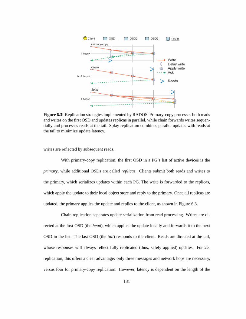
Client OSD1 OSD2 OSD3
Write
Delay write
Apply write
Ack
Reads
4 hops
4 hops
N+1 hops
Primary-copy
Chain
Splay
OSD4
Figure 6.3: Replication strategies implemented by RADOS. Primary-copy processes both readsand writes on the first OSD and updates replicas in parallel, while chain forwards writes sequen-tially and processes reads at the tail. Splay replication combines parallel updates with reads atthe tail to minimize update latency.
writes are reflected by subsequent reads.
With primary-copy replication, the first OSD in a PG’s list of active devices isthe
primary, while additional OSDs are calledreplicas. Clients submit both reads and writes to
the primary, which serializes updates within each PG. The write is forwardedto the replicas,
which apply the update to their local object store and reply to the primary. Once all replicas are
updated, the primary applies the update and replies to the client, as shown in Figure 6.3.
Chain replication separates update serialization from read processing. Writes are di-
rected at the first OSD (thehead), which applies the update locally and forwards it to the next
OSD in the list. The last OSD (thetail) responds to the client. Reads are directed at the tail,
whose responses will always reflect fully replicated (thus, safely applied) updates. For 2×
replication, this offers a clear advantage: only three messages and network hops are necessary,
versus four for primary-copy replication. However, latency is dependent on the length of the
131

Write
Delay write
Apply update
Ack
Commit to disk
CommitT
ime
Client Head Replica Tail
Figure 6.4: RADOS responds with anackafter the write has been applied to the buffer cacheson all OSDs replicating the object (shown here with splay replication). Only after it has beensafely committed to disk is a secondcommitnotification sent to the client.
chain, making the strategy problematic for high levels of replication.
Splay replication combines elements of the two. As with chain replication, updates
are directed at the head and reads at the tail. For high levels of replication,however, updates
to the middle OSDs occur in parallel, lowering the latency seen by the client. Both primary-
copy and splay replication delay the local write in order to maintain strong consistency in the
presence of an OSD failure, although splay must do so for less time, lowering OSD memory
requirements.
6.3.2 Serialization versus Safety
RADOS disassociates write acknowledgement from safety at all levels in order to
provide both efficient update serialization and strong data safety. This approach is illustrated in
Figure 6.4, which corresponds to the splay scheme shown in Figure 6.3 with an additional set
of messages. During a replicated write, each replica OSD sends anack to the tail immediately
after applying the update to the in-memory cache of the local EBOFS object store, and the
tail responds to the client with anackonly after all replicas have applied the update (as before).
132

Later, when EBOFS provides each OSD with asynchronous notification that the update is safely
committed to disk, they send a second message to the tail, and only after all replicas have done so
is the client sent a finalcommit. The strategy is similar for the other schemes: with primary-copy
replication,acks andcommitsgo to the primary instead of the tail, and with chain replication,
only commitsgo to the tail (the replicated update itself is an implicitack).
Once clients receive anack, they can be sure their writes are visible to others, and
synchronous application level calls can typically unblock. Clients buffer all updates until a
commitis received, however, allowing clients to participate in recovery if all OSDsreplicating
the update fail, losing their in-memory (uncommitted) state.
6.3.3 Maps and Consistency
Tagging all RADOS messages—both those originating from clients and from other
OSDs—with the map epoch ensures that all update operations are applied in afully consistent
fashion. Because all replicas are involved in any given update operation, any relevant map
updates (i. e. any update that changes PG membership) will be discovered. Even if the master
copy of the cluster map has been updated to change a particular PGs membership, updates may
still be processed by the old members, provided they have not yet heard of the change. Because
a given set of OSDs who are newly responsible for a PG cannot becomeactive (i. e. recover or
service I/O) without consulting prior members or determining they are failed (see Section 6.3.5),
no updates can be lost, and consistency is maintained.
Achieving similar consistency for read operations is slightly less natural thanfor up-
dates. In the event of a partial network failure that results in an OSD becoming only partially
133

5’12
5’11
4’10
4’9
4’8
4’7
last_update
3’5
3’4
3’3
last_complete
tim
e
bottom
= update
= deletionabc
abc
def
ghi
def
abc
ghi
def
5’11abc
4’10def
Log Missing
topversionop versionobject
ghi
object
Figure 6.5: Each PG has a log summarizing recent object updates and deletions. The mostrecently applied operation is indicated bylast update. All updates abovelast completeareknown to have been applied, while any missing objects in the interval betweenlast completeandlast updateare summarized in the missing list.
unreachable, the OSD servicing reads for a PG could be declared “failed” but still be reachable
by clients with an old map. Meanwhile, the updated map may specify a new OSD in its place.
In order to prevent any read operations from being processed by theold OSD after new updates
are be processed by the new one, we require timely heartbeat messages between OSDs in each
PG in order for the PG to remain available (readable). That is, if the OSD servicing reads hasn’t
heard from other replicas inH seconds, reads will block. Then, in order for a new OSD to take
over that role from another OSD, it must either obtain positive acknowledgement from the old
OSD (ensuring they are aware of their role change), or delay for the same time interval. In my
implementation, I choose a relatively short heartbeat interval of two seconds. This ensures both
timely failure detection and a short interval of PG data unavailability in the eventof a primary
OSD failure.
134
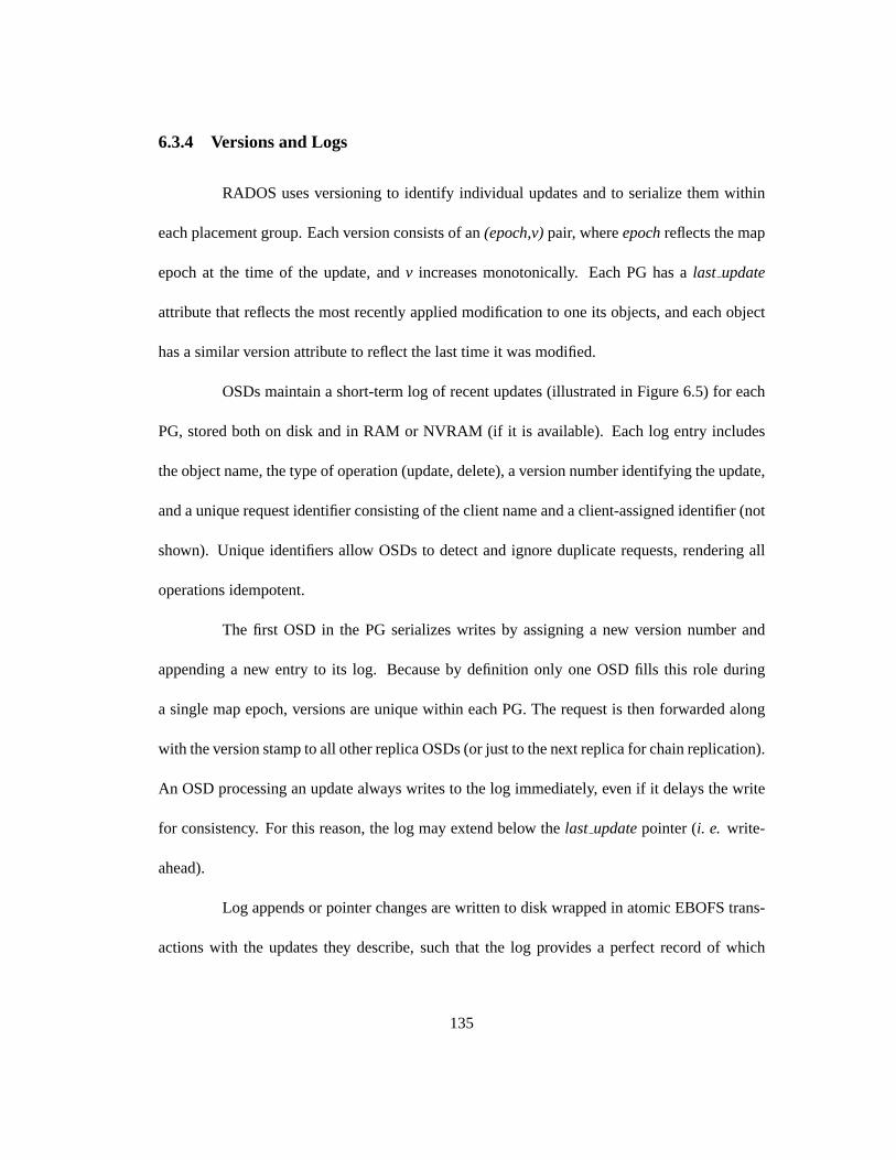
6.3.4 Versions and Logs
RADOS uses versioning to identify individual updates and to serialize them within
each placement group. Each version consists of an(epoch,v)pair, whereepochreflects the map
epoch at the time of the update, andv increases monotonically. Each PG has alast update
attribute that reflects the most recently applied modification to one its objects, andeach object
has a similar version attribute to reflect the last time it was modified.
OSDs maintain a short-term log of recent updates (illustrated in Figure 6.5) for each
PG, stored both on disk and in RAM or NVRAM (if it is available). Each log entry includes
the object name, the type of operation (update, delete), a version number identifying the update,
and a unique request identifier consisting of the client name and a client-assigned identifier (not
shown). Unique identifiers allow OSDs to detect and ignore duplicate requests, rendering all
operations idempotent.
The first OSD in the PG serializes writes by assigning a new version number and
appending a new entry to its log. Because by definition only one OSD fills this role during
a single map epoch, versions are unique within each PG. The request is then forwarded along
with the version stamp to all other replica OSDs (or just to the next replica for chain replication).
An OSD processing an update always writes to the log immediately, even if it delays the write
for consistency. For this reason, the log may extend below thelast updatepointer (i. e. write-
ahead).
Log appends or pointer changes are written to disk wrapped in atomic EBOFStrans-
actions with the updates they describe, such that the log provides a perfect record of which
135

updates were (and were not) committed before any crash (see Section 7.1). The log also forms
the basis for recovery when a PG is being brought up to date or replicatedto an entirely new
OSD. All updates below thelast completeare known to be applied locally, while amissing
list summarizes the latest versions of modified objects above it. OSDs periodically trim their
on-disk logs when requests have been fully flushed to disk on all replicasand clients have been
notified.
6.3.5 Failure Recovery
RADOS failure recovery is driven entirely by cluster map updates and subsequent
changes in each PG’s list of active devices. Such changes may be due todevice failures, re-
coveries, cluster expansion or contraction, or even complete data reshuffling from a totally new
CRUSH replica distribution policy—RADOS makes very few assumptions aboutwhat kind of
map changes are possible. For example, a PG might go from three OSDs to none (a complete
power failure) to one OSD (after partial power is restored) and then to twoentirely different
OSDs (a reorganization), and these changes may happen very quickly,without a sufficient in-
terval between each transition to allow recovery to complete. Moreover, when an OSD crashes
and recovers, EBOFS object store will be warped back in time to the most recent snapshot
committed to disk.
In all cases, RADOS employs a robustpeeringalgorithm to establish a consistent
view of PG contents and to restore the proper distribution and replication of data. This strategy
relies on the basic design premise that OSDs aggressively replicate the PG log and its record
of what the current state of a PGshouldbe (i. e. what object versions it contains), even when
136

some object replicas may be missing locally. Thus, even if recovery is slow and object safety is
degraded for some time, PG metadata is carefully guarded, simplifying the recovery algorithm
and allowing the system to reliably detect data loss.
6.3.5.1 Peering
When an OSD receives a cluster map update, it walks through all new map incremen-
tals up through the most recent to examine and possibly adjust PG state values. Any locally
stored PGs whose active list of OSDs changes are markedinactive, indicating that they must
re-peer. Considering all map epochs (not just the most recent) ensures that intermediate data
distributions are taken into consideration: if an OSD is removed from a PG andthen added
again, it is important to realize that intervening updates to PG contents may haveoccurred. As
with replication, peering (and any subsequent recovery) proceeds independently for every PG
in the system.
The process is driven by the first OSD in the PG (theprimary). For each PG an OSD
stores for which it is not the current primary (i. e. it is a replica, or astraywhich is longer in the
active set), aNotify message is sent to the current primary. This message includes basic state
information about the locally stored PG, includinglast update, last complete, the bounds of the
PG log, andlast epochstarted, which indicates the most recent known epoch during which the
PG successfully peered.
Notify messages ensure that an OSD that is the new primary for a PG discovers its new
role without having to consider all possible PGs (of which there may be millions)for every map
change. Once aware, the primary generates aprior set, which includes all OSDs that may have
137

participated in the PG sincelast epochstarted. Because this is a lower bound, as additional
notifies are received, its value may be adjusted forward in time (and the priorset reduced). The
prior set is explicitly queried to solicit a notify to avoid waiting indefinitely for a prior OSD
that does not actually store the PG (e. g. if peering never completed for an intermediate PG
mapping).
Armed with PG metadata for the entire prior set, the primary can determine the most
recent update applied on any replica, and request whatever log fragments are necessary from
prior OSDs in order to bring the PG logs up to date on active replicas. That is, the primary
must assemble a log that stretches from the oldest log bottom on active replicas to the newest
log bottom (most recent update) on any prior OSD. Because the log only reflects recent history,
this may not be possible (e. g. if the primary is new to the PG and does not have any PG
contents at all), making it necessary for the primary to generate or request abacklog. A backlog
is an extended form of the log that includes entries above thetop pointer (where the log was
last trimmed) to reflect any other objects that exist in the PG (i. e. on disk) but have not been
modified recently. The backlog is generated by simply scanning locally storedPG contents and
creating entries for objects with versions prior to the log top. Because it does not reflect prior
deletions, the backlog is only a partial record of the PG’s modification history.
Once the primary has assembled a sufficient log, it has a complete picture of the most
recent PG contents: they are either summarized entirely by the log (if it has a backlog), or the
recent log in combination with locally stored objects. From this, the primary updates itsmissing
list by scanning the log for objects it does not have (those updated after its previouslast update).
All OSDs maintain a missing list for active PGs, and include it when logs are requested by the
138

primary. The primary can infer where objects can be found by looking at which OSDs include
the object in their log but don’t list it as missing.
Once the log and missing list are complete, the PG is ready to be activated. The
primary first sends a message to all OSDs in the prior set (but not in the active set) to update
last epochstarted. Once this is acknowledged, the primary sets its own PG toactive, and sends
a log fragment to each OSD in the active set to bring them up to date and mark them active
as well. Updatinglast epochstartedon residual OSDs implicitly renders themobsoletein that
they know the PG became active in an epoch after theirlast updateand their information is
likely out of date. In the future, a primary left with only obsolete information from its prior set
can opt to either consider itself crashed or, if an administrator is desperate, bring the PG online
with potentially stale data.
6.3.5.2 Recovery
A critical advantage of declustered replication is the ability to parallelize failurere-
covery [4, 112]. Replicas shared with any single failed device are spread across many other
OSDs, and each PG will independently choose a replacement, allowing re-replication to just as
many more OSDs. On average, in a large system, any OSD involved in recovery for a single
failure will be either pushing or pulling content for only a single PG, making recovery very fast.
The recovery strategy in RADOS is motivated by the observation that I/O is most
often limited by read (and not write) throughput. A simple recovery strategy isfor each OSD
to independently walk through its PG log and “pull” any objects on its missing list from other
OSDs, updatinglast completealong the way, until it reaches the bottom of the log. Although
139

this strategy works (and was used by previous versions of the system), ithas two limitations.
First, if multiple OSDs are independently recovering objects in the same PG, theirre-
covery will not be synchronized. That is, they will probably not pull thesame objects from the
same OSDs at the same time, resulting in duplication of the most expensive aspect of recovery:
seeking and reading. Second, the update replication protocols (described in Section 6.3.1) be-
come increasingly complex if replica OSDs are missing the objects being modified.Although
the primary OSD can simply delay updates on missing objects until they are recovered (since
it is responsible for ordering requests), replicas do not have that flexibility, which significantly
complicates consistency logic.
For these reasons, recovery in RADOS is coordinated by the primary. Asbefore, op-
erations on missing objects are delayed until the primary has a local copy. Since the primary
already knows which objects all replicas are missing from the peering process, it can preemp-
tively “push” any missing objects that are about to be modified to replica OSDs, simplifying
replication logic while also ensuring that the object is only read once. If a replica is handling
reads, as in splay replication, requests for missing objects are delayed until the object can be
pulled from the primary. If the primary is pushing an object (e. g. in response to a pull request),
or if it has just pulled an object for itself, it will always push to all replicas that need a copy
while it has the object in memory. Thus, in the aggregate, every re-replicated object is read only
once.
140

6.3.5.3 Client Participation
If a RADOS client has an outstanding (i. e. un-acked or un-committed) request sub-
mitted for a PG that experiences a failure, it will simply resubmit the request (with the same
unique request identifier) to the new PG primary. This ensures that if the request was not com-
pletely replicated or otherwise did not survive the failure, it will still be processed. If the OSD
discovers the request was already applied by the request’s presencein the log, it will consider
the operation ano-op, but will otherwise process (i. e. replicate) it normally so that the client
still receives anackandcommitwith the same associated promises.
6.3.5.4 Concurrent Failures
If all OSDs participating in a PG simultaneously fail, the PG is said to havecrashed,
and data becomes unavailable until at least one device comes back online (e. g.after a temporary
power failure). Recovery, however, is hindered by the probable lossof some updates that were
applied and serialized but existed only in RAM. This is problematic, because some clients may
have already read the applied (but uncommitted, and now lost) updates.
In order to preserve strong consistency in such situations, OSDs includethe version
associated with each update in the clientack, and the RADOS client buffers all updates it sub-
mits until a finalcommitis received. If a PG with which it has uncommitted updates crashes, the
client includes the previously assigned version with the resubmitted request.When a crashed
PG is recovering, OSDs enter areplay period for a fixed amount of time (e. g. 30 seconds)
after peering but before becoming active. The primary OSD buffers requests such that when the
replay period ends, it can reorder any requests that include versionsto reestablish the original
141

order of updates.
From the client’s perspective, this preserves consistency: the versionnumber in the
ackallows the client to reassert the correct ordering (if need be), as long as the client doesn’t
fail before receiving acommit. As described, however, the strategy has a critical flaw that
compromises strong consistency semantics: if a read operation is allowed after the update is
applied and theackis sent, such that it sees the effects, but the OSD subsequently fails suchthat
the ack (and update version) never reaches the client, the client will be unable to reassert the
previously established (and witnessed) ordering. Although it is improbable, the asynchronous
messaging model makes such a scenario possible. In fact, it would be impossible for the OSD
to be sure the client received the ack without the client confirming it with an additional message
(like a two-phase commit) and an associated increase in latency and protocolcomplexity.
For this reason, RADOS can delay reads to uncommitted data, while taking stepsto
expedite their commit to disk (see Figure 6.6). This approach maintains a low latency for writes,
and only increases latency for reads if two operations are actually dependent (i. e. reference
overlapping byte ranges in a data object, a relatively rare occurrence inmost workloads [8,
77]). Alternatively, a small amount of NVRAM can be employed on the OSD for PG log
storage, allowing serialization to be preserved across power failures such that resubmitted client
operations can be correctly reordered, similarly preserving fully consistent semantics.
6.3.6 Client Locking and Caching
Although individual object updates are both strongly consistent and atomic, many
applications require atomicity across multiple objects [63, 100]. In contrast tosystems that
142

Write
Delay write
Apply update
Ack
Commit to disk
Commit
Read
Delay readT
ime
Client Head Replica Tail
Figure 6.6: Reads in shared read/write workloads are usually unaffected by write operations.However, reads of uncommitted data can be delayed until the update commits. This increasesread latency in certain cases, but maintains a fully consistent behavior forconcurrent read andwrite operations in the event that all OSDs in the placement group simultaneously fail and thewrite ack is not delivered.
use a distributed lock manager [51, 86, 94, 107], RADOS locks are issued and enforced by
the OSDs that store objects. Read (shared) and write (exclusive) locksare implemented as
object attributes, and lock acquisition and release behave like any other object update: they are
serialized and replicated across all OSDs in the PG for consistency and safety. Locks can either
time out (i. e. be treated as leases) or applications can empower a third party to revoke onbehalf
of failed clients.
An ObjectCachermodule layers on top of the RADOS client to manage client lock
state and provide basic object caching services and multi-object updates.The ObjectCacher
transparently acquires the necessary locks to achieve proper cache consistency (read locks on
cached objects and write locks to allow write-back). Write locks can also be used to mask
latency associated with large updates: ordering is established when the lockis acquired, and is
released asynchronously as the data is written back to the OSD. Operationson multiple objects
practice deadlock avoidance during lock acquisition.
143

Write Size (KB)4 16 64 256 1024 4096
Per
−O
SD
Thr
ough
put
(MB
/sec
)
0
10
20
30
40
50
60
no replication2x replication3x replication
Figure 6.7: Per-OSD write performance. The horizontal line indicates the upper limit imposedby the physical disk. Replication has minimal impact on OSD throughput, although if thenumber of OSDs is fixed,n-way replication reduces totaleffectivethroughput by a factor ofnbecause replicated data must be written ton OSDs.
6.4 Performance and Scalability
I examine the performance, scalability, and failure recovery behavior ofthe RADOS
architecture. I begin by examining the performance of individual OSDs, and evaluate write la-
tency in light of the three replication strategies I implement. Scalability is considered indepen-
dently in terms of the specific performance-limiting factors. Finally, I discuss failure recovery
and its effect on system performance.
Performance tests are conducted using OSDs running on dual-processor Pentiums
with SCSI disks. In my experiments, RADOS achieves perfect linear scalingup to 24 OSDs,
after which throughput is limited by the network switch.
6.4.0.1 OSD Throughput
I first measure the I/O performance of a 14-node cluster of OSDs. Figure 6.7 shows
per-OSD throughput (y) with varying write sizes (x) and replication. Workload is generated by
144

Write Size (KB)4 16 64 256 1024
Writ
e La
tenc
y (m
s)
0
5
10
15
20no replication2x replication3x replicationsync writesync lock, async write
Figure 6.8: Write latency for varying write sizes and primary-copy replication. More thantwo replicas incurs minimal additional cost for small writes because replicatedupdates occurconcurrently. For large synchronous writes, transmission times dominate. Clients partially maskthat latency for writes over 128 KB by acquiring exclusive locks and asynchronously flushingthe data.
400 clients on 20 additional nodes. Performance is ultimately limited by the raw diskbandwidth
(around 58 MB/sec), shown by the horizontal line. Replication doubles ortriples disk I/O,
reducing client data rates accordingly when the number of OSDs is fixed.
6.4.0.2 Write Latency
Figure 6.8 shows the synchronous write latency (y) for a single writer with varying
write sizes (x) and primary-copy replication. Because the primary OSD simultaneously re-
transmits updates to all replicas, small writes incur a minimal latency increase formore than
two replicas. For larger writes, the cost of retransmission dominates; 1 MB writes (not shown)
take 13 ms for one replica, and 2.5 times longer (33 ms) for three. High updatelatencies are
mitigated for writes over 128 KB with the client ObjectCacher module, which uses exclusive
locks to establish serialization for large writes, while flushing data to OSDs andreleasing locks
asynchronously. Under such circumstances, latencies are determined by the exchange of lock
145

Replication Level (replicas)1 2 3 4 5 6 7 8
Writ
e La
tenc
y (m
s)
0
1
2
3
4primary−copychainsplay
Figure 6.9: Latency for 4 KB writes under different replication strategies and levels of repli-cation. Splay replication augments chain replication with parallel replica updates to achieveperformance similar to primary-copy replication for high levels of replication.
requests, providing latency for isolated large writes which approaches that of small writes.
Figure 6.9 shows the latency associated with different replication strategiesfor small
4 KB writes. Although chain replication offers the lowest latency for 2× replication, where a
minimum number of messages are exchanged, it performs poorly with large numbers of repli-
cas. Primary-copy masks the latency for replication above 2× by parallelizing updates. Splay
replication combines the best of both approaches—optimal message exchange for 2× and par-
allel updates with more replicas—with the added bonus of lowering memory utilization on the
tail OSD.
Figure 6.10 shows latency incurred per replica (y) for various replication levels (x)
with 1 MB writes. For large writes, the benefits of parallel updates are limited byper-device
bandwidth limitations. Here, the crossover point shifts from around 2× to 5×, giving chain
replication a slight edge.
146
Replication Level (replicas)1 2 3 4 5 6 7 8
Writ
e La
tenc
y (m
s/re
plic
a)
9
10
11
12
13
14primary−copychainsplay
Figure 6.10: Normalized write latency per replica for 1 MB writes under different replicationstrategies and levels of replication. Parallel replication does not improve latency for replicationslevels below six.
6.4.1 Scalability
The scalability of RADOS is potentially limited by three primary factors: the qual-
ity of the data distribution generated by CRUSH, interaction with the monitor cluster, and the
effective distribution of cluster map updates. Other elements of the system are trivially par-
allelizable. In particular, failure detection, failure recovery, and replication are all bounded on
each OSD by the number of peers, regardless of the cluster size. For our purposes, I assert that a
sufficiently large and fast network can be constructed to service many thousands of OSDs [42].
CRUSH includes some provisions for segregating replication traffic (by keeping all replicas in-
side a suitably large domain), but I otherwise consider the network to be outside the scope of
this work.
147

OSD Cluster Size2 6 10 14 18 22 26
Per
−O
SD
Thr
ough
put
(MB
/sec
)
30
40
50
60
crush (32k PGs)crush (4k PGs)hash (32k PGs)hash (4k PGs)linear
Figure 6.11: OSD write performance scales linearly with the size of the OSD cluster until theswitch is saturated at 24 OSDs. CRUSH and hash performance improves when more PGs lowervariance in OSD utilization.
6.4.1.1 Data Placement
As seen in Chapter 5, CRUSH produces a distribution of data that closely matches
the mean and variance of a binomial or normal distribution [101], meaning it appears random,
even though it is a deterministic and constrained mapping. The primary consequence is that
the varianceσ2 in the number PGs per OSD—and subsequently, in OSD storage utilizations
and workloads—is related to the average number of PGs per OSD (µ), whereσ2 ≈ µ. With an
average of 100 PGs per OSD, the standard deviationσ is 10%; with 1000 per OSD,σ drops to
3%. This behavior holds even for large clusters composed of heterogeneous (i. e. non-uniformly
weighted) devices.
Figure 6.11 shows per-OSD write throughput as the cluster scales using CRUSH, a
simple hash function, and a linear striping strategy to distribute data in 4096 or 32768 PGs
among available OSDs. Linear striping balances load perfectly for maximum throughput to
provide a benchmark for comparison, but like a simple hash function, it failsto cope with
148

device failures or other OSD cluster changes. Because data placement with CRUSH or a hash is
stochastic, throughputs are lower with fewer PGs: greater variance in OSD utilizations causes
request queue lengths to drift apart under this entangled client workload.
Although a probabilistic data distribution means that some devices may become over-
loaded (i. e. handle many more thanµ PGs) with small probability, PGs can be explicitly
diverted away from specific devices using the overload mechanism in CRUSH. Unlike the hash
and linear strategies, CRUSH also minimizes data migration under cluster expansion while
maintaining a balanced distribution.
Most importantly, the computational cost of calculating a CRUSH mapping isO(logn)
for a cluster of sizen, allowing mappings in the tens of microseconds for even extremely large
clusters.
6.4.1.2 Monitor Interaction
The monitor cluster is designed both for extreme reliability and for high availability.
In the general case, monitors do very little work—they process small messages in response to
failures, but are otherwise idle. A worst case load for the monitor cluster occurs when large
numbers of OSDs appear to fail in a short period. If each OSD storesµ PGs andf OSDs fail,
then an upper bound on the number of failure reports generated is on the order of µ f , which
could be very large if a large OSD cluster experiences a network partition.To prevent such
a deluge of messages, OSDs throttle and batch failure reports, imposing an upper bound on
monitor load proportional to the cluster size.
Although failures may be reported to multiple random monitors multiple times, only
149

the first few reports of a given failure will be forwarded to the elected lead monitor. Map up-
dates are quickly propagated among monitors such that subsequent reports of the same failures
will be reflected by the current map and result in an immediate response to the OSD. For this
reason, OSDs send heartbeats to peers at semi-random intervals to stagger detection of failures,
dispersing reports for a given failure over time. Furthermore, map updates returned to a report-
ing OSDs will also reflect all other failures processed to date, preventingsome future failure
reports from being sent.
6.4.1.3 Map Propagation
The RADOS map distribution algorithm (Section 6.2.5) ensures that updates reach all
OSDs after only logn hops. However, as the size of the storage cluster scales, the frequency of
device failures and related cluster updates increases. Because map updates are only exchanged
between OSDs who share PGs, the hard upper bound on the number of copies of a single update
an OSD can receive is proportional toµ.
In simulations under near-worst case propagation circumstances with regular map
updates, I found that update duplicates approach a steady state even withexponential cluster
scaling. In this experiment, the monitors share each map update with a single random OSD,
who then shares it with its peers. In Figure 6.12 I vary the cluster sizex and the number of
PGs on each OSD (which corresponds to the number of peers it has) andmeasure the number
of duplicate map updates received for every new one (y). Update duplication approaches a
constant level—less than 20% ofµ—even as the cluster size scales exponentially, implying
a fixed map distribution overhead. I consider a worst-case scenario in which the only OSD
150

Cluster size (OSDs)64 128 256 512 1024
Map
dup
licat
ion
(dup
s/ac
tual
)
0
10
20
30
40
5080 PGs per OSD
160 PGs per OSD
320 PGs per OSD
Figure 6.12: Duplication of map updates received by individual OSDs as the size of the clustergrows. The number of placement groups on each OSD effects number ofpeers it has who mayshare map updates.
chatter consists of ping messages for failure detection, which means that, generally speaking,
OSDs learn about map updates (and the changes known by their peers) as slowly as possible.
Limiting map distribution overhead thus relies only on throttling the map update frequency,
which the monitor cluster already does as a matter of course.
6.4.2 Failure Recovery
Figure 6.13 shows write throughput over time as a cluster of 20 (real) OSDsrecovers
from two (simulated) failures at time 30. 30 clients are writing data with 2× replication and
saturating the cluster. As the failed OSDs are initially marked down, replication throughput
drops because affected PGs are temporarily unreplicated, while effective client write perfor-
mance correspondingly increases. At time 50 the OSDs are marked out andrecovery is initi-
ated. Performance drops while active and then inactive objects are re-replicated to other OSDs,
151

time (seconds)0 30 60 90 120
Clu
ster
Thr
ough
put (
MB
/sec
)
0
100
200
300
400
500
writereplicationrecovery
Figure 6.13: Write throughput over time as a saturated 20 OSD cluster recovers from twoOSDfailures at time 30. Data re-replication begins at time 50 and completes at time 80.
time (seconds)0 30 60 90 120 150
Clu
ster
Thr
ough
put (
MB
/sec
)
0
50
100
150
200
250writereplicationrecovery
Figure 6.14: Write throughput over time as an unsaturated 20 OSD cluster recovers from oneOSD failure at time 30 and two more at time 80.
152

but throughput eventually returns to a level slightly below baseline (due to the two missing
OSDs). The throughput penalty associated with recovery is exaggerated in this experiment for
two reasons. First, in such a small cluster, all OSDs either share data with thefailed devices,
or are selected as replacements in one or more PGs. In a large system, eachOSD failure will
initiate recovery for only a single PG (of a hundred or more) on each of its peers. Second, the
relatively naive implementation currently makes almost no attempt to balance recovery with
regular workload. Nevertheless, recovery proceeds quickly in parallel and the cluster resumes
performing at only a slightly degraded level after about 30 seconds.
This is evident in Figure 6.14, which shows first one and then two OSDs failures on
an only partially loaded cluster. The first recovery minimally effects throughput both because
more disk bandwidth is available and because fewer PGs contain data to be replicated. The
second recovery involves more PGs and more data, with a greater impact on performance.
6.5 Future Work
Although RADOS was developed for use in the Ceph distributed file system [100],
the reliable and scalable object storage service it provides is well-suited for a variety of other
storage abstractions. In particular, the current interface based on reading and writing byte ranges
is primarily an artifact of the intended usage for file data storage. Objects might have any query
or update interface or resemble any number of fundamental data structures. Potential services
include distributed B-link trees that map ordered keys to data values (as in Boxwood [63]),
high-performance distributed hash tables [90], or FIFO queues (as in GFS [30]).
153

Although RADOS manages scalability in terms of total aggregate storage and ca-
pacity, this dissertation does not address the issue of many clients accessing a single popular
object. I have implemented aread sheddingmechanism which allows a busy OSD to shed reads
to object replicas for servicing, when the replica’s OSD has a lower load and when consistency
allows (i. e. there are no conflicting in-progress updates). Heartbeat messages exchange infor-
mation about current load in terms of recent average read latency, suchthat OSDs can determine
if a read is likely to be service more quickly by a peer. This facilitates fine-grained balancing in
the presence of transient load imbalance, much like D-SPTF [62]. Notably,this read shedding
is only possible with primary-copy replication, as the OSD servicing reads must be aware of
any in-progress writes in order to preserve consistency. Although preliminary experiments are
promising, a comprehensive evaluation has not yet been conducted.
More generally, the distribution of workload in RADOS is currently dependent on the
quality of the data distribution generated by object layout into PGs and the mapping of PGs to
OSDs by CRUSH. Although I have considered the statistical properties of such a distribution
and demonstrated the effect of load variance on performance for certain workloads, the interac-
tion of workload, PG distribution, and replication can be complex. For example, write access to
a PG will generally be limited by the slowest device storing replicas, while workloads may be
highly skewed toward possibly disjoint sets of heavily read or written objects. I have conducted
only minimal analysis of the effects of such workloads on efficiency in a cluster utilizing declus-
tered replication, or the potential for techniques like read shedding to improve performance in
such scenarios.
Although total device failure is addressed, OSDs do not currently consider partial
154
failures, like corrupted disk blocks. Checksums or preemptive mechanismslike disk scrubbing
would dramatically improve data safety.
The integration of intelligent disk scheduling, including the prioritization of repli-
cation versus workload and quality of service guarantees, is an ongoingarea of investigation
within the research group [109].
6.6 Related Work
Most distributed storage systems utilize centralized metadata servers [1, 14,30] or
collaborative allocation tables [86] to manage data distribution, ultimately limiting system scal-
ability. For example, like RADOS, Ursa Minor [1] provides a distributed object storage service
(and, like Ceph, layers a file system service on top of that abstraction). In contrast to RADOS,
however, Ursa Minor relies on an object manager to maintain a directory of object locations and
storage strategies (replication, erasure coding, etc.), limiting scalability and placing a lookup in
the data path. RADOS does not provide the same versatility as Ursa Minor’s dynamic choice of
timing and failure models, or support for online changes to object encoding(although encod-
ing changes are planned for the future); instead, RADOS focuses on scalable performance in a
relatively controlled (non-Byzantine) environment.
The Sorrento [93] file system’s use of collaborative hashing [47] bears the strongest
resemblance to RADOS’s application of CRUSH. Many distributed hash tables(DHTs) use
similar hashing schemes [21, 80, 90], but these systems do not provide thesame combination
of strong consistency and performance that RADOS does.
155
For example, DHTs like PAST [80] rely on an overlay network [81, 90, 114] in order
for nodes to communicate or to locate data, limiting I/O performance. More significantly, ob-
jects in PAST are immutable, facilitating cryptographic protection and simplifying consistency
and caching, but limiting the systems usefulness as a general storage service. CFS [21] utilizes
the DHash DHT to provide a distributed peer-to-peer file service with cryptographic data pro-
tection and good scalability, but performance is limited by the use of the Chord [90] overlay
network. In contrast to these systems, RADOS targets a high-performance cluster or data cen-
ter environment; a compact cluster map describes the data distribution, avoiding the need for an
overlay network for object location or message routing.
Most existing object-based storage systems rely on controllers or metadata servers
to perform recovery [14, 68], or centrally micro-manage re-replication [30], failing to leverage
intelligent storage devices. Other systems have adopted declustered replication strategies to
distribute failure recovery, including OceanStore [52], Farsite [2], and Glacier [37]. These
systems focus primarily on data safety and secrecy (using erasure codes or, in the case of Farsite,
encrypted replicas) and wide-area scalability (like CFS and PAST), but not performance.
FAB (Federated Array of Bricks) [82] provides high performance by utilizing two-
phase writes and voting among bricks to ensure linearizability and to respondto failure and
recovery. Although this improves tolerance to intermittent failures, multiple bricks are required
to ensure consistent read access, while the lack of complete knowledge ofthe data distribu-
tion further requires coordinator bricks to help conduct I/O. FAB can utilize both replication
and erasure codes for efficient storage utilization, but relies on the useof NVRAM for good
performance. In contrast, RADOS’s cluster maps drive consensus and ensure consistent access
156

despite a simple and direct data access protocol. RADOS’s cluster map bears some resemblance
to layout epochs in Palladio [35]: epoch numbers version views of the cluster membership and
state, per-store layouts resemble RADOS’s PGs and tolerance of cluster map differences when
they are not significant, and similar policies guide failure handling and updates. Unlike Palla-
dio, however, RADOS manages cluster maps using a Paxos-like protocol among a dedicated
cluster of monitors, and distributes updates with a lazy map distribution approachthat is tightly
integrated with the data access protocol. This simplifies consensus management, while also
avoiding the distributed search and manager selection mechanisms required by Palladio to arbi-
trate access to healthy stores and recovery from failure. In contrast toboth FAB and Palladio,
RADOS provides high-performance access to data via a comparatively simple read and update
protocol, and (of course) exposes an object-based (instead of block-based) interface.
Wiesmannet al. [105] compare replication in distributed systems and databases,
including those that rely onatomic broadcastor view synchronous broadcastgroup communi-
cation primitives to simplify consistency management. RADOS does not utilize atomic broad-
cast or similar primitives because comparable ordering guarantees are provided by the use of a
primary copy and ordered message delivery. RADOS’s primary copy approach is analogous to
eager primary copy database solutions like that in INGRES [91], although incontrast to repli-
cated databases, replicated storage systems benefit from deterministic updates and inexpensive
updates, while the processing associated with databases transactions suggests alternative ap-
proaches. This distinction is illustrated in a performance comparison of database replication
strategies based on total order broadcast later conducted by Wiesmannet al. [106]: the per-
formance of active replication schemes (in which each node processes the update) suffers rel-
157

ative to alternative (e. g. certification) schemes in which a single node calculates the result
and broadcasts the results to replicas. Significantly, replication in RADOS further differs from
primary-copy replication as described by Wiesmann in that load remains balanced despite a
fixed (per-PG) primary due to declustering.
Version-driven consistency and logs are used in many primary-copy replication sys-
tems. Like RADOS, Harp [61] uses logs to facilitate efficient recovery from transient failures,
and utilizes a limited form of decoupled replication (administrators must manually partition data
into sub-volumes). However, although Harp relies on write-ahead logs and UPS to preserve both
performance and consistency, RADOS simply delays update application on thereadable replica,
and dissociates synchronization from safety to preserve performance. Reneseeet al. describe
a recovery mechanism for chain replication [96] that utilizes a log-like structure, although their
use of synchronous updates vastly simplifies possible failure modes, and does not address ar-
bitrary changes in the data distribution. Other brick-based storage systemsrely on a two-phase
commit to maintain update consistency [107] that (like FAB’s voting) incur a costin latency
and complexity. PRACTI replication [9] generalizes a range of consistency models and replica
placement strategies, but like the systems above, does not address the complexity of doing so in
a large-scale environment without a centrally managed metadata directory.
Sorrento utilizes version-basedconsistencymodel that targets an environment with
minimal write sharing; when update conflicts do arise, conflicting transactionsare rolled back
by simply discarding newer versions. This optimistic approach simplifies updates in the general
case at the expense of strong consistency, resulting in an interface in which application open-
modify-close sequences may fail to commit and require a retry. In contrast,RADOS writes
158

are serialized and replicated by a primary OSD, avoiding concurrent update conflicts entirely
simply by altering the flow of data.
Seneca [46] is an asynchronous remote-mirroring protocol that supports write coa-
lescing and asynchronous propagation; these features are primarily useful when a slow, wide-
area network link separates replicas and when replica consistency is allowed to diverge based
on some bounded time interval. In contrast, RADOS is designed for a cluster environment
with high speed links, and keeps all replicas consistent by applying updates synchronously.
(Although write coalescing could be used to improve recovery performance, RADOS does
not yet implement this optimization.) Jiet al. also present a taxonomy for remote mirroring
which can be applied to a range of replication strategies; RADOS can be described as in-order
asynchronous propagation, with no inter-LU (placement group) ordering, no divergence, and
full write-through (although Ji’s taxonomy does not capture RADOS’ two-phase acknowledge-
ment).
Previous systems have provided an abstract distributed object store. One of the ear-
liest is Thor [60], which focused on extending the object (as in object-oriented programming)
paradigm in a distributed environment with the notion of persistent objects. BuddyCache [10]
provides strong consistency semantics and caching for distributed applications, but it targets
small cooperating peer groups and wide area networks. Other systems relax consistency con-
straints [30] and target widely distributed and weakly connected environments [48, 53]. In
contrast, RADOS targets a large, dedicated storage cluster.
Kybos [107] provides a distributed storage service using bricks and network RAID,
with an emphasis on resource (storage and bandwidth) reservation and online adjustment of
159

placement to meet those requirements. In contrast, RADOS employs a pseudo-random distri-
bution (corrected to limit variance and avoid overload) to avoid the metadata associated with
defining explicit mappings between individual objects and devices, facilitating scalability and
avoiding directory lookup. Kenchammana-Hosekoteet al. evaluate a range of approaches to
data path, consistency, and atomicity in a simulated network RAID system [49].Although
parity-based redundancy differs from simple replication, their analysis ispartially applicable to
RADOS. Notably, they observe that shifting serialization to an OSD avoids network saturation
when client bandwidth is limited, and that the choice of data path is orthogonal tomulti-object
atomicity. In particular, a two-phase commit strategy for atomic multi-object updates—which
is planned but not yet supported by RADOS—has little performance penaltyin most circum-
stances.
Xin et al. [112] propose the use of distributed recovery as a means of improving data
safety, and conduct a quantitative analysis of system reliability with FaRM, adeclustered repli-
cation model in which—like RADOS—data objects are pseudo-randomly distributed among
placement groups and then replicated by multiple OSDs, facilitating fast parallel recovery. They
find that distributed recovery improves reliability at scale, particularly in the presence of rela-
tively high failure rates for new disks (“infant mortality”). Lianet al. [59] find that reliability
further depends on the number of placement groups per device, and that the optimal choice is re-
lated to the amount of bandwidth available for data recovery versus devicebandwidth. Although
both consider only independent failures, RADOS leverages CRUSH to mitigate correlated fail-
ure risk with failure domains.
160

6.7 Conclusions
RADOS provides a scalable and reliable object storage service without compromising
performance. By separating serialization from safety, the architecture provides strong consis-
tency semantics to applications by minimally involving clients in failure recovery.
RADOS utilizes a globally replicated cluster map that provides all parties with com-
plete knowledge of the data distribution, typically specified using a function likeCRUSH. This
avoids the need for object lookup present in conventional architectures, which RADOS lever-
ages to distribute replication, consistency management, and failure recovery among a dynamic
cluster of OSDs while still preserving consistent read and update semantics. A scalable failure
detection and cluster map distribution strategy enables the creation of extremelylarge storage
clusters, with minimal oversight by the tightly-coupled and highly reliable monitor cluster that
manages the master copy of the map.
Because clusters at the petabyte scale are necessarily heterogeneousand dynamic,
OSDs employ a robust recovery algorithm that copes with any combination ofdevice failures,
recoveries, or data reorganizations. Recovery from transient outages is fast and efficient, and
parallel re-replication of data in response to node failures limits the risk of data loss.
161
Chapter 7
Local Object Storage
Low-level object storage on individual OSDs is managed by EBOFS, an Extent and B-
tree based Object File System. Although a variety of distributed storage architectures leverage
existing general-purpose file systems [14, 55] such as ext3 [95], both the performance and
the standard POSIX file system interface and safety semantics are inappropriate for RADOS.
Because EBOFS is implemented entirely in user-space and interacts directly witha raw block
device, it is unencumbered by an unwieldy kernel file system interface, and avoids interaction
with the (Linux) VFS inode and page caches, which were designed around a different storage
abstraction and workload assumptions. This allows EBOFS to optimize specifically for object
workloads [97].
7.1 Object Storage Interface
EBOFS exposes a unique low-level storage interface that forms the basisof RADOS’s
strong consistency and safety model. Objects are accessed via a simple file-like interface that
162

provide simple read and write access to byte extents (〈o f f set, length〉 pairs). Objects can be
members of zero or more namedcollections, which are indexed to allow efficient enumeration
or changes in membership (used by RADOS to manage placement groups). Both objects and
collections accept namedattributes, which map an identifier to an variable length (but normally
small) piece of data.
In contrast to conventional file systems, EBOFS exposes an interface that supports
compound transactions that allow a sequence of operations to be groupedinto a single atomic
operation.1 A single transaction may, for instance, write data to multiple objects, adjust collec-
tion membership, update object and collection attributes, and be certain that after a failure the
operation will be either fully completed or never started. Similarly, transactionscan read both
object data and attribute values atomically without fear of race conditions. This allows RADOS
to apply an object update, modify the object version, update the PGlast update, and append an
entry to the PG log in a single atomic transaction, keeping PG metadata perfectly synchronized
with data.
EBOFS writes are usually non-blocking, applying changes to the in-memory cache
and returning immediately. Because critical metadata is kept in memory, operationsblock only
when the buffer cache is full and data is being flushed out to disk, allowingRADOS to quickly
apply updates to establish ordering semantics without waiting for disk I/O. EBOFS provides
asynchronous notification via a callback when changes are safely committedto stable storage.
1Although many kernel-based file systems support compound transactions or group commit internally for effi-ciency, they do not expose a transaction interface to applications.
163

7.2 Data Layout
Like most modern file systems [40, 92], EBOFS usesextentsto keep metadata effi-
cient. In most cases, writes are laid out on disk in large, contiguous and singular extents. Free
extents are binned by size and sorted, allowing the allocator to utilize a “closest good fit” strat-
egy in which a free extent of approximately the size required is allocated near related data or the
current write position on disk. This facilitates efficient streaming writes and future read access
while minimizing long-term fragmentation.
A generalized B-tree [19] library is used to manage most storage metadata, including
the free extent lists and the object and collection tables which map object identifiers toonode
andcnodelocations on disk. Eachonodecontains the metadata for an individual object, includ-
ing attributes, collection membership, and the list of extents containing object data. Collection
cnodesstore collection attributes. A single large B-tree is currently used to map a collection ID
to the objects it contains.
7.3 Data Safety
EBOFS maintains two superblocks, updated in an alternating fashion, to reference
current file system metadata. All other data and metadata is always written to unallocated re-
gions on disk, similar to soft updates [64] and copy-on-write B-tree updates in WAFL [40]. At
the end of eachcommit cycle, all pending changes are flushed to disk before the next superblock
is written with references to the new metadata. Pending changes are trackedsuch that subse-
quent writes do not block while waiting for prior epochs to commit. On mount, EBOFS simply
164

chooses the newer superblock, secure in the knowledge that it references a fully consistent
snapshot of the most recently committed file system state.
In contrast to conventional file systems, which typically keep newly written data in
cache before flushing it to disk (in the hopes that it will be modified again or deleted), Ceph
clients perform this function before submitting I/Os to the object store. For thisreason, EBOFS
aggressively schedules disk writes, and cancels pending disk I/O whensubsequent write or
delete operations render them obsolete. This approach maximizes the length of our I/O queues
for greater scheduling efficiency, and ensures that data reaches disk as quickly as possible.
7.4 Journaling
EBOFS can optionally employ an auxiliary journal to reduce the commit latency of
object updates. Although the separation of serialization and safety in the storage interface
largely masks the commit latency associated with the periodic cycle, certain applications (e. g.
metadata journaling) rely on both the safety and low latency of writes.
The EBOFS journal is stored on an independent storage device—ideally,one backed
by NVRAM—than the rest of the file system. The device is structured as a single ring buffer:
once the write pointer reaches the end of the device, it starts over again atthe beginning. The
journal “tail” pointer is adjusted to reclaim journal storage after each commit cycle completes
and older journal entries are no longer needed. If the journal device fills up prematurely, journal-
ing is temporarily disabled for the duration of the commit cycle until it can be safely restarted.
Each update transaction processed by EBOFS is applied first to the in-memory cache,
165

I/O Size (KB)4 16 64 256 1024 4096 16384
Per
−O
SD
Thr
ough
put (
MB
/sec
)
0
10
20
30
40
50
60
ebofsext3reiserfsxfsreads
writes
Figure 7.1: Performance of EBOFS compared to general-purpose file systems. Although smallwrites suffer from coarse locking in the prototype, EBOFS nearly saturates the disk for writeslarger than 32 KB. Since EBOFS lays out data in large extents when it is writtenin large incre-ments, it has significantly better read performance.
then queued for write in the journal. The final commit callback occurs when the journal event
flushes to the journal backing device, or when the next commit cycle completes—whichever
comes sooner. For small writes in particular, this offers a significant improvement in perfor-
mance. For large writes that are I/O bound at the disk, the duplication of datain both the journal
and the primary storage device limits the journal’s effectiveness.
7.5 Evaluation
Figure 7.1 compares the performance of EBOFS to that of general-purpose file sys-
tems (ext3, ReiserFS, XFS) in handling a Ceph workload. Clients synchronously write out
large files, striped over 16 MB objects, and read them back again. Although small read and
write performance in EBOFS suffers from coarse threading and locking, EBOFS very nearly
166

saturates the available disk bandwidth for writes sizes larger than 32 KB, and significantly out-
performs the others for read workloads because data is laid out in extentson disk that match
the write sizes—even when they are very large. Performance was measured using a fresh file
system. Experience with an early EBOFS design suggests it will experiencesignificantly lower
fragmentation than ext3, but I have not yet evaluated the current implementation on an aged file
system.
7.6 Related Work
The design of EBOFS is based largely on the design of existing file systems. Most
notably, these include XFS [92] and WAFL [40]. EBOFS, like XFS, utilizes extents and B-trees
to manage allocation and metadata. EBOFS commit strategy is similar to that found in WAFL.
Likewise, EBOFS’s journal is very similar to that used by WAFL in filers containing NVRAM.
Notably, the loss of the journal (e. g.failure of an NVRAM battery) compromises the durability
of writes during the last commit cycle, but does not affect the consistencyof the rest of the file
system.
Like FFS and most file systems that followed, EBOFS attempts to keep related data
and metadata together. However, instead of employing explicit cylinder groups, EBOFS sorts
the free extent maps by position to locate available storage space that is nearrelated data or
metadata.
Although the first incarnation of EBOFS was implemented within the Linux kernel,
the implementation was moved to user-space largely based on experience with OBFS [97],
167

another object-based file system that demonstrated excellent performance outside the kernel by
bypassing the kernel page cache with the theO DIRECT interface.
7.7 Conclusion
EBOFS provides a reliable, high-performance storage service for local object storage
on Ceph OSDs. It is based on a copy-on-write strategy that avoids overwriting any data on disk
until it has been deallocated, facilitating fast crash recovery by ensuring that the on-disk image
is consistent at all times. Its storage interface tailored specifically to the needs of RADOS, no-
tably including asynchronous notification of update commits to disk and support for compound
transactions. This facilitates atomic compound updates to both data and metadata and to mul-
tiple objects, which are used by RADOS to keep PG metadata (such as the PG log, discussed
in Section 6.3.4) consistent with object data. EBOFS includes support for ajournal stored on
an auxiliary storage device to faciliate fast update commits. It is implemented entirelyin user
space.
168

Chapter 8
Conclusion
I conclude this dissertation by first considering additional avenues of research, and
then summarizing the work presented here.
8.1 Future Work
Although the design and implementation described in this work is relatively complete—
the file system is functional and the implementation can properly tolerate most combinations of
failures—there are a number of planned augmentations and opportunities for future research.
8.1.1 MDS Load Balancing
One of the largest lessons in Ceph was the importance of the MDS load balancer to
overall scalability, and the complexity of choosing what metadata to migrate where and when.
Although in principle the design and goals seem quite simple, the reality of distributing an
evolving workload over a hundred MDSs highlights additional subtleties. Most notably, MDS
169

performance has a wide range of performance bounds, including CPU,memory (and cache ef-
ficiency), and network or I/O limitations, any of which may limit performance at any point in
time. Furthermore, it is difficult to quantitatively capture the balance between total through-
put and fairness; under certain circumstances unbalanced metadata distributions can increase
overall throughput [102].
8.1.2 Client Interaction
The basic protocol used by the client to communicate with the MDS cluster takes a
few basic steps to minimize interaction. For example, areaddir operation returns both dentry
names and inode contents, facilitating areaddirplusinterface or optionally relaxing strict client
consistency to improve application performance. However, the operation of the MDS is still
fundamentally synchronous: clients are not issued any leases to keep their metadata caches
consistent. Experience with other file systems has shown that such techniques can be quite
effective; in most workloads there are typically a small number of directories that are read-only
and heavily shared (e. g./usr).
A mechanism currently exists to delegate and call back client capabilities to facilitate
exclusive, read-only, or read-write sharing of file data; it is likely that reusing this mechanism on
a coarse per-directory basis could capture a relatively substantial improvement in metadata per-
formance. A more generalized metadata leasing mechanism would likely prove more effective,
although it would be more complicated to implement.
Systems like Envoy [79] seek to migrate metadata management to the same hardware
node as the client application. Although this is technically feasible given the Ceph MDS ar-
170

chitecture, the security and failure recovery implications of doing so have not been carefully
considered.
8.1.3 Security
The current implementation does not include any kind of distributed security—security
enforcement resembles that of NFS, in which servers trustuid andgid values embedded in each
client request. Although the architecture is based on a capability model to facilitate a strong
security infrastructure, OSDs do not yet validate capabilities. Two security architecture and
protocol variants have been proposed for Ceph [57, 69], and one has been partially implemented
(for a single-MDS system).
8.1.4 Quotas
Pollacket al. [50] describe a scalable distributed quota enforcement architecture that
is designed to work with distributed storage systems. Their architecture is based on crypto-
graphically signedvouchers, generated by a quota server, that clients can redeem with OSDs
in order to store data. Used vouchers are tracked and later reconciled,while the system further
places bounds on clients’ ability to “cheat” through voucher re-use. Work is currently underway
to implement this scheme in Ceph.
8.1.5 Quality of Service
Wu et al. [110] describe a quality of service framework designed to isolate the
performance of different classes of workloads concurrently accessing the system. EBOFS is
171
augmented with QoS-aware disk scheduling, while the statistically uniform distribution of load
provided by CRUSH is leveraged to approximate global class-based isolation. Research is on-
going in this area to further provide end-to-end performance managementwith stronger bounds
on performance [24].
8.1.6 Snapshots
One of my ulterior motives for introducing the anchor table mechanism was to pro-
vide a generic means of making inodes globally addressable. Although this was necessary for
support of multilink files, I also plan to use it to facilitate a flexible form of “snapshots” that can
be applied at any time to arbitrary subtrees of the file system hierarchy. My hope is to introduce
time extents to dentry identifiers in order to easily integrate management of namespace snap-
shots into the existing MDS, while simultaneously introducing an object-granularity versioning
abstraction to the distributed object store.
8.2 Summary
As the scalability and performance requirements for storage systems increase, system
designers must look to new architectures to meet those demands, in many cases abandoning
conventional approaches. I have described Ceph, a distributed file system that provides excellent
performance, reliability, and scalability. Ceph’s design eschews a numberof conventions in file
system design dating back to early Unix in order to push the bounds of reliableand scalable
performance.
172

Metadata in Ceph is managed by a distributed, adaptive, fault-tolerant cluster of meta-
data servers (MDSs) that collectively forms a high-performance consistent cache of the file sys-
tem namespace (Chapter 4). Metadata is stored with file metadata (inodes) embedded inside
their containing directories, and each MDS maintains an extremely large journal, dramatically
improving the I/O profile generated by a busy MDS server, while support for POSIX hard links
is preserved through an auxiliary table. Workload is partitioned in terms of thefile system
namespace—made possible in part by the embedded inode strategy—allowing the cluster to
adapt to changing file system workloads to effectively utilize available resources.
Scalability and self-management in RADOS is made possibly in part through the
use of CRUSH, and specialized data distribution function that logically takes of the place of a
conventional allocation table. CRUSH (described in Chapter 5) allows the location of a data
object to be cheaply calculated when it is needed, eliminating the need to store object locations
in a table or query a directory service. CRUSH provides functionality similar toa hash function,
while taking additional steps to ensure that object locations are stable when devices fail or join
the cluster. Most importantly, the algorithm addresses reliability in the presence of correlated
failures through the use of a flexible, hierarchical placement strategy.
RADOS (Chapter 6) enables the management of a large, dynamic cluster of stor-
age devices by distributing data replication, failure detection, and failure recovery to intelligent,
semi-autonomous devices. A cluster map ensures a consistent view of cluster state and data lay-
out, facilitating consistent read and update semantics despite a lazy update propagation scheme.
This allows replication, failure detection, and recovery to be managed in a decentralized and
scalable fashion, with minimal oversight from the tightly-coupled cluster of monitors responsi-
173

ble for the master copy of the cluster map. The update protocol separates synchronization from
safety in order to improve performance while preserving strong consistency and data safety
semantics, enabling excellent performance, data safety, and scalability in adynamic cluster
environment.
In addition to describing key enabling components of Ceph’s design, I have evaluated
a working prototype of the system under a range of benchmarks and real-world workloads,
demonstrating excellent performance, reliability, and system scalability.
174

Appendix A
Communications Layer
A.1 Abstract Interface
Message passing in Ceph is based on a simple abstract messaging interfacethat de-
fines node addressing and naming, methods for sending and receiving messages, and a notifica-
tion mechanism for handling delivery failures.
Each node in Ceph has both a logical name and a network address associated with it.
The logical name (e. g. mds0, osd1) will typically remain the same across restarts, as it refers
to the node’s role in the system, while the address is (by design) unique for every incarnation
of a daemon or process participating in the system. The address consists ofthe IP address
and port used for sending messages to the given node, as well as a (typically random) nonce
value to keeps the address unique, even across starts. This allows othernodes in the system to
easily determine whether a peer has restarted (and potentially lost shared state) by comparing
addresses.1
1In certain cases, the nonce values are not used. The monitors’ address nonce values are fixed at 0 since commu-
175

A.2 SimpleMessenger
SimpleMessenger is an implementation of the abstract communications interface that
utilized TCP for message transport. The use of TCP naturally provides reliable, ordered deliv-
ery as well as notification of communication faults (in the form of connection drops). When a
message is queued for a new peer, a TCP session is established, and the peers identify them-
selves to ensure that their nonce values match and the address is not stale.Once established,
messages can be passed across the same TCP session in both directions. An orderly connection
teardown process is used to shut down the session to ensure that no messages are lost.
The implementation currently makes no attempt to retry in the event of a commu-
nications error, which makes it relatively vulnerable to certain types of intermittent network
problems. For example, packet loss is tolerated relatively well (eventually causing a timeout),
while routing changes can cause an immediate TCP session drop. Although explicit message
receipt acknowledgement and buffering of outgoing messages would allow the implementation
to transparently attempt reconnect and redelivery without violating the ordering requirements,
this has not yet been implemented.
A.3 FakeMessenger
FakeMessenger is an alternate implementation of the messaging interface that isused
for debugging purposes. Messages are exchanged between logicalentities existing within a sin-
gle process’s address space. Because no inter-process communication mechanism is provided,
nication with the monitors is stateless.
176

multiple logical system components (OSDs, metadata servers, clients, monitors)are compiled
and executed within the same process. Sent messages are simply added to in-memory queues,
and later delivered in a round-robin fashion that ensures that only a single message is begin
processed at a time (for ease in debugging).
177

Appendix B
MDS Implementation Details
This appendix describes certain elements of the MDS implementation in greater de-
tail. In particular, I describe the structure of the distributed cache and the mechanisms through
which replication consistency is preserved in the face of failure.
B.1 MDS Distributed Cache
Central to the dynamic subtree partitioning approach is the treatment of the file system
as a hierarchy. The file system is partitioned by delegating authority for subtrees of the hierarchy
to different metadata servers. Delegations may be nested: /usr may be assigned to one MDS,
for instance, while /usr/local is reassigned to another. In the absence ofan explicit subtree
assignment, however, the entire directory tree nested beneath a point is assumed to reside on the
same server.
Implicit in this structure is the process of hierarchy traversal in order fornested in-
odes to be located and opened for subsequent descent into the file hierarchy. Such path traversal
178

is also necessary to verify user access permissions for nested items as required by POSIX se-
mantics. Although this process may seem costly for locating a file deep within the directory
hierarchy, the locality of reference typical of both scientific and general purpose computing
workloads [28, 98] allows those costs to be amortized over subsequent accesses to the same
directories. More importantly, unlike LH permission management [15], a hierarchically defined
structure allows the system to move or change the effective permissions of arbitrarily sized
subtrees of the directory tree by modifying the relevant ancestor directory with fixed cost. Like-
wise, individual subtrees of the hierarchy are fully independent fromtheir siblings; semantics
are dependent only on the prefix (ancestor) directories leading to the root of the file system.
B.1.1 Cache Structure
All metadata that exists in the cache is attached directly or indirectly to the root in-
ode1. That is, if the /usr/bin/vi inode is in the cache, then /usr/bin, /usr, and / aretoo, including
the inodes, directory objects, and dentries. Only leaf items may be expired from the cache;
directories may not be removed until items contained within them are expired first. This al-
lows permission verification for all known items to proceed without any additional I/O costs,
and for hierarchical consistency to be preserved. It also facilitates theembedding of inodes in
directories.1Metadata may also be rooted by astray inode; see section B.1.1.3.
179
B.1.1.1 Directory Fragments
Directory contents are managed in terms of one or more directory fragments (dir
frags) that are associated with each directory inode. In most cases, there is a single fragment
that contains the full directory contents. In certain cases, however, directory contents are broken
up to ease load balancing. Each directory fragment is stored in a different object in the object
store, allowing them to be managed completely independently of each other.
Fragments are described by a binary split tree (afrag tree) stored in the directory
inode. Each directory fragment corresponds to afrag, which is defined by a bit pattern and
mask. Much like network names and masks in IP networking, the mask specifieswhich bits
are significant and compared to the bit pattern. For example, frag 12/4 is a 4bit mask and a
matching bit pattern of 12 (1100 in binary). Directory entries are mapped intofragments by
hashing the filename to an integer value and then matching that against all fragments in the
fragtree.2
Because the cache structure is defined such that a directory inode has any number
of children (depending on its fragmentation level), the subtree partitioning mechanisms can be
leveraged to individually delegate directory fragments to other nodes in the cluster. This allows
all of the existing infrastructure for migration and failure recovery to be re-used, while providing
a simple internal abstraction for breaking large or busy directory into smallerpieces.
2The implementation is considerably more efficient than this sounds; mapping a hash value to a fragment in afragtree isO(logn), wheren is the number of fragments.
180

B.1.1.2 Dentries and Inodes
Each directory fragment is a collection directory entries, or dentries. Because Ceph
embeds inodes into the directories that reference them, this gives rise to two types of dentries.
The first (or only) dentry to reference an inode is called theprimary, and is always accompanied
by the inode itself.Remotedentries reference an inode by number only; an additional lookup
in the anchor table may be required to locate the inode itself. Anull dentry is also possible (at
least in-memory) to capture caching or locking state for a name that is does not (yet) reference
an inode but it still of interest (e. g. for replicating knowledge of a name’s non-existence), or to
capture thedirty state for a deleted file.
B.1.1.3 The “Stray” Directory
Because the cache is structured such that all inodes are associated with aprimary
dentry, management of files that are open for I/O but have been unlinkedfrom the namespace
present a problem. Maintaining the primary dentry/inode relationship is desirable because of
the subtree-based approach for partitioning workload and the existing metadata storage infras-
tructure.
To maintain that arrangement, unlinked files are moved into a hiddenstraydirectory if
it is not possible for them to be immediately removed. Each MDS maintains a separate stray di-
rectory inode (with potentially many directory fragments), allowing operationsthat unlink files
from the namespace to proceed locally on each MDS. Stray directory inodes have predictable
numbers (based on the MDS node), allowing discovery and replication of stray metadata on
other MDS nodes, and allowing unlinked inodes to be referenced by the anchor table.
181

B.1.2 Replication and Authority
The authority maintains a list of what nodes cache each inode. Additionally, each
replica is assigned a nonce (initial 0) to disambiguate multiple replicas of the same item (see
below).
map<int, int> replicas; // maps replicating mds# to nonce
The replicas setalwaysincludes all nodes that cache the particularly object, but may
additionally include nodes that used to cache it but recently trimmed it from theircache. In
those cases, an expire message should be in transit. We have two invariants:
1. The authority’s replica set will always include all actual replicas, and
2. cache expiration notices will be reliably delivered to the authority.
The second invariant is particularly important because the presence of replicas will
pin the metadata object in memory on the authority, preventing it from being trimmed from
the cache. Notification of expiration of the replicas is required to allow previously replicated
objects to eventually be trimmed from the cache as well.
Each metadata object has a authority bit that indicates whether it is authoritative or
a replica. Although this information is also discernible from the subtree partition, the bits are
faster to check and provide an additional sanity check for debugging.
Each replicated object maintains a ”nonce” value, issued by the authority atthe time
the replica was created. If the authority has already created a replica forthe given MDS, the new
replica will be issues a new (incremented) nonce. This nonce is attached to cache expirations,
182

and allows the authority to disambiguate expirations when multiple replicas of the same object
are created and cache expiration is coincident with replication. (In certaincases, the authority
may push a new replica to another MDS to ensure that a replica exists there for some operation.)
That is, when an old replica is expired from the replicating MDS at the same time that a new
replica is issued by the authority and the resulting messages cross paths, theauthority can tell
that it was the old replica that was expired and effectively ignore the expiration message. A
replica is removed from the authority’s replicas map only if the nonce matches.
B.1.3 Subtree Partition
Authority of the file system namespace is partitioned using a subtree-based partition-
ing strategy. This strategy effectively separates directory inodes fromdirectory contents, such
that the directory contents are the unit of re-delegation. That is, if / is assigned to mds0 and
/usr to mds1, the inode for /usr will be managed by mds0 (it is part of the / directory), while the
contents of /usr (and everything nested beneath it) will be managed by mds1.
The description for this partition exists solely in the collective memory of the MDS
cluster and in the individual MDS journals. It is not described in the regular on-disk metadata
structures. This is related to the fact that authority delegation is a property of the directory
fragmentand not the directory’sinode.
Subsequently, if an MDS is authoritative for a directory inode and does not yet have
any state associated with the directory in its cache, then it can assume that it is also authoritative
for the directory.
Directory state consists of a data object CDir that describes any cached dentries con-
183

tained in the directory, information about the relationship between the cachedcontents and what
appears on disk, and any delegation of authority. Each CDir object has adir auth element. Nor-
mally dir auth has a value of AUTHPARENT, meaning that the authority for the directory is
the same as the directory’s inode. When dirauth specifies another metadata server, that direc-
tory is point of authority delegation and becomes asubtree root. A CDir is a subtree root IFF
its dir auth specifies an MDS id (and is not AUTHPARENT). That is,
1. A dir is a subtree root IFF dirauth != AUTH PARENT.
2. If dir auth = AUTH PARENT then the inode auth == dir auth, but the converse may not
be true.
The authority for any metadata object in the cache can be determined by following
the parent pointers toward the root until a subtree root CDir object is reached, at which point
the authority is specified by its dirauth.
Each MDS cache maintains a subtree data structure that describes the subtree partition
for all objects currently in the cache:
map< CDir*, set<CDir*> > subtrees;
A dirfrag (represented by a CDir) will appear in the subtree map (as a key) IFF it is a
subtree root. The map value is a set of all other subtree roots nested immediately beneath that
point. Nested subtree roots effectively bound or prune a subtree. Forexample, if we had the
following partition:MDS Pathmds0 /mds1 /usrmds0 /usr/localmds0 /home
184

The subtree map on mds0 would beSubtree Bounds/ (/usr, /home)/usr/local ()/home ()
and on mds1:
Subtree Bounds/usr (/usr/local)
B.2 Metadata Storage
Ceph metadata is stored in regular objects in the shared object store. This is advan-
tageous primarily because it keeps all metadata in a shared medium, facilitating migration of
metadata authority between nodes and recovery in the event of failure. Metadata resides both in
the per-MDS journals and primary per-directory fragment objects (see Chapter 4).
B.2.1 Directory Fragments and Versioning
Metadata updates that exist in the MDS journal but not in the regular metadataobjects
are calleddirty and pinned in the MDS cache. In order to keep track of which updates have
been committed, each inode, dentry, and dir object in the MDS cache maintains aversion value.
Versions are generated relative to the directory fragment that contains them, since that is the
underlying unit for metadata storage: when a cache item is dirtied, its new version value is
generated by incrementing the directory fragment version.
Each directory fragment maintains four version values:version, the current version;
projectedversion, the anticipated version pending updates that are still being journaled; and
committingversionand committedversion, the last versions to be queued for or commit to
185

disk. The projected version values are assigned to updates that are currently being written to the
journal, but have not yet been applied to the in-memory metadata cache (andwhose side-effects
are thus not yet visible). Thus,committed<= committing<= version<= pro jected.
The committed version normally indicates the version of the directory that is written
to stable storage on disk. Any directory entry or inode contained in the directory with a version
value greater than this should be flagged as dirty in the cache. After journal replay due to
an MDS recovery from a failure, however, the MDS does not know the committed version of
directory fragments it extracted from the journal (it would be expensiveto probe all of these
objects just to find out). In this case, the committed version is zero, and many cache items may
be marked as dirty (due to journaled updates) even though they were safely stored by the prior
incarnation of the MDS. When such a directory isfetchedfrom disk, it will compare dirty dentry
versions with the actual committed version and mark any unnecessarily dirty itemsclean.
When a directory item is removed, it is replaced by a (dirty and versioned)null dentry.
This ensures that the deletion is reflected in the cache until the directory is committed. Clean
null dentries can be safety trimmed.
Each directory fragment has acompleteflag that indicates whether all directory con-
tents are currently cached. If any non-null item is expired from the cache, the flag is cleared.
Currently, directory fragments can only be committed to disk in their entirety, which means that
a fetch must sometimes be conducted (to fill in any missing contents) before a commit (i. e. a
read-modify-write). Partial commits will be made possible in the future by extending the object
interface to provide a key/value interface in addition to the simple byte extent (file-like) model.
A higher-resolution complete flag (e. g.one with a separate bit for different subsets of the den-
186

try namespace, or a Bloom filter [11]) would allow create operations to safely proceed without
caching the complete directory fragment contents.
B.2.2 Journal Entries
Journal entries reflect metadata updates that have not yet beencommittedto the per-
directory metadata storage. Entries employ a commonmetablobstructure for describing meta-
data updates. Each metablob consists of one or more directory fragment IDs, dentries, and
inodes. Normally, each updated item in the metablob is accompanied by any ancestor metadata
necessary to connect it to the root of the current subtree. Journal trimming is constrained such
that at all times any non-obsolete journal entry is preceded by a SubtreeMap entry that includes
all subtree roots and bounds, with ancestor metadata up to the filesystem root.Thus, as long
as replay begins with a SubtreeMap, all included metadata can be placed properly within the
hierarchy.
Metadata objects in the metablob also include a few flags: namely, all items may be
marked dirty, and directory fragments may be markedcomplete. Thedirty flag simply sets the
object’s dirty flag when the entry is replayed after a failure, inducing an eventual commit of the
containing directory fragment. The complete flag likewise sets the fragment’s complete flag; it
is used only when migrating subtrees between MDS nodes when the fragment’s entire contents
are included in the metablob.
A few other metadata updates can be described by the metablob, allowing them tobe
committed atomically with other updates. These include anchor table transactions (see below),
inode number allocations, inode truncations, and client request identifiers(which are journaled
187
to keep all operations idempotent from the perspective of the client).
B.2.3 Anchor Table
The anchor table is an auxiliary structure, managed by a single MDS, that allows in-
odes to be located within the directory hierarchy by their inode number. It is necessary because
Ceph lacks a conventional inode table that facilitates inode lookup by inode number. Inode
contents are always embedded in directories adjacent to a directory entrythat references them.
Because they can exist only in one place, that dentry is deemed theprimary dentry. Any addi-
tional remote dentriesrefer simply to the inode number.
Because there are no back pointers from the inode to reference remote dentries, and
because directory renames can affect arbitrarily large portions of the hierarchy, it is necessarily
to be able to locate the actual inode contents within the hierarchy with only an inode number.
This is accomplished byanchoringonly those inodes who have multiple hard links or directories
inodes with children having multiple hard links. The anchor table maintains back pointers with
reference counts for all anchored inodes to the directory fragment that contains them.
For example, if/usr/bin/nano and/usr/lib/ld.so have additional hard links,
the table might look like Figure B.1.
This simple structure for the anchor table keeps the overall size of the table relatively
small (particularly when considering that in most cases, very few inodes have multiple hard
links). It also is easy to update when directory renames effect large portions of the hierarchy:
only the backpointer for the renamed item, the reference count for its immediateold and new
parents, and any missing ancestors need to be updated in the table.
188

Path Inode Parent Ref/usr/bin/nano 123 12#0 1/usr/bin 12 10#0 1/usr/lib/ld.so 456 11#0 1/usr/lib 11 10#0 1/usr 10 1#0 2/ 1 1
Table B.1: Sample anchor table with two anchored inodes. Note that the full path is shownonly for illustration and is not part of the table. The hash mark (#) in the parent column is usedto denote a particular fragment of the given directory, where 0 indicates the directory is notfragmented. The /usr entry has a ref count of two because it is referenced by both /usr/bin and/usr/lib.
Anchor table queries return all records necessary to reach the root for the given in-
ode. Updates are conducted with a two-phase commit. The anchor table MDS first journals a
prepareevent. The resulting transaction ID is included in the journaled metablob for theatomic
operation effecting the update, and acommitevent is later journaled by the anchor table MDS
to close the transaction.
B.3 Migration
B.3.1 Cache Infrastructure
B.3.1.1 Ambiguous Authority
While metadata for a subtree is being migrated between two MDS nodes, the dirauth
for the subtree root is allowed to be ambiguous. That is, it will specify both the old and new
MDS IDs to indicate that a migration is in progress.
If a replicated metadata object is expired from the cache from a subtree whose author-
189
ity is ambiguous, the cache expiration is sent to both potential authorities. This ensures that the
message will be reliably delivered, even if either of those nodes fails. A number of alternative
strategies were considered. Sending the expiration to the old or new authority and having it
forwarded if needed can result in message loss if the forwarding node fails. Pinning ambiguous
metadata in cache is computationally expensive for implementation reasons, anddelaying the
transmission of expiration messages is difficult to implement because the replicating MDS must
send the final expiration messages only when the subtree authority is disambiguated, forcing it
to keep certain elements of it cached in memory. Although duplicating expirationsincurs a
small communications overhead, the implementation is much simpler and easier to verify.
B.3.1.2 Auth Pins
Most operations that modify metadata must allow some amount of time to pass in
order for the operation to be journaled or for communication to take place between the object’s
authority and any replicas. For this reason it must not only be pinned in the authority’s metadata
cache, but also be locked such that the object’s authority is not allowed to change until the
operation completes. This is accomplished usingauth pins, which increment a reference counter
on the object in question, as well as all parent metadata objects up to the rootof the subtree. As
long as the pin is in place, it is impossible for that subtree (or any fragment ofit that contains
one or more auth pins) to be migrated to a different MDS node. Auth pins can be placed on
inodes, dentries, and directories.
Auth pins can only exist for authoritative metadata, because they are only created if
the object is authoritative, and their presence prevents the migration of authority.
190

B.3.1.3 Freezing
More specifically, auth pins prevent a subtree from beingfrozen. When a subtree is
frozen, all updates to metadata are forbidden. This includes updates to thereplicas map that
describes which replicas (and nonces) exist for each object.
In order for metadata to be migrated between MDS nodes, it must first be frozen. The
root of the subtree is initially marked asfreezing. This prevents the creation of any new auth
pins within the subtree. After all existing auth pins are removed, the subtree isthen marked as
frozen, at which point all updates are forbidden. This allows metadata state to be packaged up
in a message and transmitted to the new authority, without worrying about intervening updates.
If the directory at the base of a freezing or frozen subtree is not also asubtree root (that
is, it has dirauth == AUTH PARENT), the directory’s parent inode is auth pinned. A frozen
tree root dir will authpin its inode IFF it is authoritative AND not a subtree root. This prevents
a parent directory from being concurrently frozen, and a range of resulting implementation
complications relating to determining the bounds of the frozen region.
B.3.1.4 Cache Expiration for Frozen Subtrees
Cache expiration messages that are received for a subtree that is frozen are temporar-
ily set aside instead of being processed. Only when the subtree is unfrozen are the expirations
either processed (if the MDS is authoritative) or discarded (if it is not). Because either the
exporting or importing metadata can fail during the migration process, the MDS cannot tell
whether it will be authoritative or not until the migration completes.
During a migration, the subtree will first be frozen on both the exporter andimporter,
191

and then all other replicas will be informed of a subtree’s ambiguous authority. This ensures
that all expirations during migration will go to both parties, and nothing will be lost in the event
of a failure.
B.3.2 Normal Migration
The exporter begins by doing some checks in exportdir() to verify that it is permissi-
ble to export the subtree at this time. In particular, the cluster must not be degraded, the subtree
root may not be freezing or frozen, and the full path must be read locked (i. e. not conflicted with
a rename). If these conditions are met, the subtree root directory is temporarily auth pinned,
the subtree freeze is initiated, and the exporter is committed to the subtree migration, barring an
intervening failure of the importer or itself.
An MExportDiscover message sent from the exporter to the importer serves simply
to ensure that the inode for the base directory being exported is open on the destination node.
It is pinned by the importer to prevent it from being trimmed. This occurs before the exporter
completes the freeze of the subtree to ensure that the importer is able to replicate the necessary
metadata. When the exporter receives the MDiscoverAck, it allows the freeze to proceed by
removing its temporary auth pin.
The MExportPrep message then follows to populate the importer with a spanning tree
that includes all directories, inodes, and dentries necessary to reach any nested subtrees within
the exported region. This replicates metadata as well, but it is pushed out bythe exporter,
avoiding deadlock with the regular discover and replication process. Theimporter is responsible
for opening the bounding directory fragments from any third parties authoritative for those
192

subtrees before acknowledging. This ensures that the importer has correct dir auth information
about where authority is re-delegated for all points nested beneath the subtree being migrated.
While processing the MExportPrep, the importer freezes the entire subtreeregion to prevent
any new replication or cache expiration.
A warning stage occurs only if the base subtree directory is open by nodes other
than the importer and exporter. If it is not, then this implies that no metadata within ornested
beneath the subtree is replicated by any node other than the importer an exporter. If it is,
then a MExportWarning message informs any bystanders that the authority for the region is
temporarily ambiguous, and lists both the exporter and importer as authoritativeMDS nodes.
In particular, bystanders who are trimming items from their cache must send MCacheExpire
messages to both the old and new authorities (see above). Lock-related messages are also
delayed until the authority is no longer ambiguous.
The exporter walks the subtree hierarchy and packages up an MExport message con-
taining all metadata and important state (e. g. information about metadata replicas). At the
same time, the exporter’s metadata objects are flagged as non-authoritative.The MExport mes-
sage sends the actual subtree metadata to the importer. Upon receipt, the importer inserts the
data into its cache, marks all objects as authoritative, and logs a copy of all metadata in an
EImportStart journal message. Once that has safely flushed to the journal, it replies with an
MExportAck. The exporter can now log an EExport journal entry, which ultimately specifies
that the export was a success. In the presence of failures, it is the existence of the EExport entry
only that disambiguates authority during recovery.
Once logged, the exporter will send an MExportNotify to any bystanders,informing
193

them that the authority is no longer ambiguous and cache expirations should besent only to
the new authority (the importer). Once these are acknowledged back to the exporter, implicitly
flushing the bystander to exporter message streams of any stray expirationnotices, the exporter
unfreezes the subtree, cleans up its migration-related state, and sends a final MExportFinish to
the importer. Upon receipt, the importer logs an EImportFinish(true) (noting locally that the
export was indeed a success), unfreezes its subtree, processes any queued cache expirations,
and cleans up its state.
B.4 Failure Recovery
MDS recovery after a failure (e. g. host crash, process segfault, sufficiently long
network outage) is made possible by the journal kept by each MDS. Journal replay is compli-
cated, however, because not all state is written to the journal. Although all metadata updates are
logged, the state of the distributed cache (i. e. which nodes have in-memory replicas of which
metadata) is not. Furthermore, some metadata operations involve multiple metadata objects on
different MDS nodes, requiring a two-phase commit and a resolution stageduring recovery.
The full recovery process is broken down into four stages. During thereplaystage,
the MDS simply re-reads the contents of the journal, accumulating state in memory.During
the resolvestage, the fate of any two-phase updates are determined. Duringreconnect, client
sessions are reestablished. Finally, during therejoin stage, MDS nodes exchange information
about what metadata objects are replicated with peers in the cluster, reestablishing distributed
cache and lock state.
194

Certain stages of the recovery occur with respect to therecovery set, the set of MDS
nodes that were participating in the cluster at the time of the first failure. Onceone failure has
occurred, the cluster is considereddegraded, and no new MDS nodes are allowed to join (unless
they are taking over for a failed node) or leave until all nodes have fully recovered.
B.4.1 Journal Replay
Journal replay is relatively straightforward. The Journaler interfaceis used to read and
write to a journal constructed with objects in the distributed object store, and probes the journal
size on its own. Replay begins at the last known expire point (the journal’ssize metadata is only
written periodically). Each journal event is read from the journal in sequence, and it’s replay()
method is called to recover its state. The only caveat to replay is that events prior to the first
SubtreeMap event are ignored. Once the first subtree map is replayed,the remainder of the
journal is processed in its entirety.
When replay completes, the MDS moves to theresolvestage, unless it is the only
MDS in the cluster, in which case it moves directly to thereconnectstage.
B.4.2 Resolve Stage
The resolvestage serves to disambiguate the fate any operations that span multiple
metadata servers. These include imports of subtrees of metadata (migrations from other MDS
nodes to the current node), updates to the anchor table, and client operations likerenameor
unlink that sometimes affect metadata managed by different MDS nodes.
An MDS entering the resolve stage begins by sending a Resolve message to all other
195

resolving nodes in the recovery set. Surviving MDS nodes also send a Resolve message to any
MDS that enters the resolve stage. The Resolve message includes a summaryof all subtrees
currently managed by that node (specified as the root dirfrag and its list of bounds, if any), a
list of ambiguous imports (subtrees that were partially imported when the failureoccurred), and
a list of uncommitted slave request IDs (for updates initiated by the target MDS, but affecting
metadata on the recovering node). Ambiguous imports and uncommitted slave requests are
defined by the presence of aprepareevent in the journal but no matchingcommitted, or (in
the case of a surviving MDS sending a Resolve to a recovering MDS) by the corresponding
in-memory state.
The recovering MDS waits for Resolve messages from all other MDS nodes, assim-
ilating information about subtree authority for metadata it has recovered from the journal by
setting its CDir dirauth values appropriately. If the Resolve message lists uncommitted slave
requests, a ResolveAck message is sent in response that specifies which requests committed and
aborted. Ambiguous imports are noted, but not processed until all Resolve messages have been
processed. At that point, subtree authority ambiguities are be resolved bysimply checking if
authority for an ambiguous subtree is claimed by another node: if it is, the import clearly didn’t
complete.
Once subtree authority has been resolved, the recovering node trims all non-authoritative
metadata from its cache, with the exception of that necessary to connect authoritative subtrees
to the root. On recovery, the MDS has no way of knowing whether non-authoritative metadata
was subsequently updated, requiring all such metadata to be revalidated during the rejoin stage;
trimming non-authoritative metadata reduces the amount of metadata that must be exchanged,
196

allowing that process to complete more quickly, and significantly simplifies the process.
B.4.3 Reconnect Stage
The recovering MDS next reestablishes connectivity with any clients with whom it
had open sessions at the time of the crash. It announces itself by sendingeach client a copy of the
current MDSMap (which specifies that the sending MDS is in the reconnectstate). In response,
each client sends an MClientReconnect, which lists any open files, their fullpathname, and
issued capabilities. This is necessary primarily because the MDS does not (synchronously)
journal file opens. Although the file inode number is often sufficient to restore state, the full
path name (noted by the client at the time the file was successfully opened) is included in case
the inode was not replayed from the journal (e. g. , it was not recently modified). The MDS
updates the inodefile lockstate such that it is compatible with the currently issued capabilities
(e. g. if multiple clients have the read and write capability bits, the lock is put in themixed
state).
B.4.4 Rejoin Stage
During therejoin stage, state about locks and the replication of metadata in memory is
reestablished between MDS nodes. This replication state is necessary forthe distributed MDS
cache and locking to function, but is too expensive to journal. Rejoin involves both recovering
MDS nodes (those that crashed and have replayed their journal) and those that have survived
(not failed).
A recovering MDS begins the rejoin process only after all other recovering nodes also
197

reach the rejoin stage. At that point, each MDS sends a message summarizingwhat metadata it
replicates. Such messages come in two varieties:weakor strong, depending on whether it is a
recovering or surviving MDS, respectively. A recovering node expects a rejoin (either strong or
weak) from every other node in the cluster. Surviving MDS nodes sendstrong rejoin messages
to each recovering node only (i. e. not to other survivors).
B.4.4.1 Weak and Strong Rejoin
The initial rejoin message is a declaration of replication, sent from an MDS replicating
metadata to the metadata’s authoritative MDS. Aweak rejoinis sent by nodes recovering from
a failure. Rejoin messages are generated by walking all subtrees in the node’s subtree map for
which it is not authoritative, and declaring any replicated metadata object in the message bound
for its authority. The declarations consist of dirfrag identifiers (inode number and frag), dentry
names and types, and inode numbers. The weak rejoin also includes a list ofall locally open
files and capabilities that clients have declared during the reconnect stagethat do not fall within
subtrees the recovering node is authoritative for.
A strong rejoin is sent by surviving MDS nodes, and also includes the lock states
associated with each replicated object, any capabilities that are wanted by clients with locally
opened files, and any slave authpins or xlocks held by client requests currently being processed.
The strong rejoin does not include an enumeration of open files.
A recovering node may thus receive a combination of weak and strong rejoin mes-
sages, depending on whether its peers also suffered a failure. A surviving node will only receive
weak rejoins (from recovering nodes); surviving nodes have lost no shared state and do not re-
198

join with each other.
When processing a weak rejoin, the MDS will check for any capability exports it
should claim. (Such client capabilities are migrated to the authoritative MDS much like they
are during a subtree migration.) If the inode does not already exist in the cache, it will add
the path to a list of inodes to load (see below; surviving nodes will always have the inode in
their cache). The MDS will then walk the list of replica declarations, adding the sender to the
appropriate metadata object replica maps. If the node is recovering, the dirlock on directories
will also be set to the SCATTER state to ensure that any remote mtime updates are captured.
If a surviving MDS node receives a weak rejoin (the sender is therefore a recovering
node), the rejoin consists of an exhaustive list of items replicated by the sender. The recipient
(survivor) takes the additional step of scouring its own cache for objects that were previously
replicated by the sender node but were not recovered from the journal, and adjusting their replica
maps accordingly.
Once a recovering node receives a rejoin from all other nodes, it fetches any metadata
for previously issued (or imported) capabilities from disk. Capability imports are then processed
(by updating the issued state and notifying the client). Finally, rejoin acks aregenerated for all
replicated metadata in the cache.
B.4.4.2 Ack
An ack message is generated in response to each weak or strong rejoin. The ack
contains a newly issued nonce for each replicated object, as well as the initial states to initialize
replica locks.
199

If the rejoin recipient is a survivor, it can immediately respond with an ack, because
metadata object locks are in a known correct state. If the rejoin recipient isa recovering node,
however, it must first wait until all rejoins have been received beforeresponding, in case any of
its peers includes a strong declaration that forces a lock into a non-default state.
Once a recovering node receives all expected rejoins and acks, it moves from the
rejoin to theactivestate.
B.4.4.3 Missing and Full
It is possible that a strong rejoin will include declarations for replicated metadata
objects that are not in the recovering node’s local cache (i. e. were not in the journal). In
this case, it is less expensive to acquire those metadata objects from the surviving MDS node
than from disk. To allow the rejoin to proceed smoothly, the recovering nodesimply creates
any metadata objects that are missing, and flags inodes to indicate their contentsare (as yet)
undefined. The recovering node generates amissingmessage for the sender that lists any inodes
it lacked.
The surviving node responds with afull message that includes the full inode contents
(inode t struct, symlink target, and/or dirfrag tree).
200

B.5 Anchor Table
B.5.1 Table Updates
Anchor table updates are based on a two phase commit. The MDS initiating an update
sends apreparerequest to the anchor table MDS. The prepare is identified by the inode number
and operation type; only one operation for each type (create, update, destroy) can be pending
per inode at any time. Both parties may actually be the same MDS node, but for simplicity we
treat that situation the same. (That is, we act as if they may fail independently, even though they
can’t.)
The anchor table journals the proposed update, and responds with anagreemessage
and a anchor table version number. This uniquely identifies the request.
The initiating MDS can then update the file system metadata however it sees fit (e. g.
to perform anunlink or rename). When it is finished and the operation has been journaled, it
sends acommitmessage to the anchor table. The table journals the commit, frees any state from
the transaction, and sends anack. The initiating MDS should then journal theack to complete
the transaction.
B.5.2 Failure Recovery
B.5.2.1 Anchor Table MDS Failure
If the anchor table fails before journaling theprepareand sending theagree, the
initiating MDS will simply retry the request.
If the anchor table fails after journalingpreparebut before journalingcommit, it will
201

resendagreeto the initiating MDS.
If the anchor table fails after thecommit, the transaction has been closed, and it takes
no action. If it receives acommitfor which it has no open transaction, it will reply withack.
B.5.2.2 Initiating MDS Failure
If the MDS fails before the metadata update has been journaled, no action is taken,
since nothing is known about the previously proposed transaction. If anagreemessage is re-
ceived and there is no correspondingprepareor pending-commit state, androllback is sent to
the anchor table.
If the MDS fails after journaling the metadata update but before journaling theack, it
resendscommitto the anchor table. If it receives anagreeafter resending thecommit, it simply
ignores theagree. The anchor table will respond with anack, allowing the initiating MDS to
journal the finalackand close out the transaction locally.
On journal replay, each metadata update (metablob) encountered that includes an an-
chor transaction is noted in the anchor table client by adding it to the pendingcommit list, and
each journaledack is removed from that list. Journal replay may encounteracks with no prior
metadata update; these are ignored. When recovery finishes, acommitis sent for all outstanding
transactions.
202

Bibliography
[1] Michael Abd-El-Malek, William V. Courtright II, Chuck Cranor, Gregory R. Ganger,
James Hendricks, Andrew J. Klosterman, Michael Mesnier, Manish Prasad, Brandon
Salmon, Raja R. Sambasivan, Shafeeq Sinnamohideen, John D. Strunk, Eno Thereska,
Matthew Wachs, and Jay J. Wylie. Ursa minor: versatile cluster-based storage. InPro-
ceedings of the 4th USENIX Conference on File and Storage Technologies(FAST), pages
59–72, San Francisco, CA, December 2005.
[2] Atul Adya, William J. Bolosky, Miguel Castro, Ronnie Chaiken, GeraldCermak, John R.
Douceur, John Howell, Jacob R. Lorch, Marvin Theimer, and Roger Wattenhofer. FAR-
SITE: Federated, available, and reliable storage for an incompletely trusted environment.
In Proceedings of the 5th Symposium on Operating Systems Design and Implementation
(OSDI), Boston, MA, December 2002. USENIX.
[3] Peter A. Alsberg and John D. Day. A principle for resilient sharing of distributed re-
sources. InProceedings of the 2nd International Conference on Software Engineering,
pages 562–570. IEEE Computer Society Press, 1976.
[4] Guillermo A. Alvarez, Walter A. Burkhard, and Flaviu Cristian. Tolerating multiple
203

failures in RAID architectures with optimal storage and uniform declustering. In Pro-
ceedings of the 24th Int’l Symposium on Computer Architecture, pages 62–72, Denver,
CO, June 1997. ACM.
[5] Eric Anderson, Joseph Hall, Jason Hartline, Michael Hobbs, AnnaR. Karlin, Jared Saia,
Ram Swaminathan, and John Wilkes. An experimental study of data migration algo-
rithms. In Proceedings of the 5th International Workshop on Algorithm Engineering,
pages 145–158, London, UK, 2001. Springer-Verlag.
[6] Eric Anderson, Michael Hobbs, Kimberly Keeton, Susan Spence, Mustafa Uysal, and
Alistair Veitch. Hippodrome: running circles around storage administration. In Proceed-
ings of the 2002 Conference on File and Storage Technologies (FAST), Monterey, CA,
January 2002.
[7] Alain Azagury, Vladimir Dreizin, Michael Factor, Ealan Henis, Dalit Naor, Noam Rinet-
zky, Ohad Rodeh, Julian Satran, Ami Tavory, and Lena Yerushalmi. Towards an object
store. InProceedings of the 20th IEEE / 11th NASA Goddard Conference on MassStor-
age Systems and Technologies, pages 165–176, April 2003.
[8] Mary G. Baker, John H. Hartman, Michael D. Kupfer, Ken W. Shirriff, and John K.
Ousterhout. Measurements of a distributed file system. InProceedings of the 13th ACM
Symposium on Operating Systems Principles (SOSP ’91), pages 198–212, October 1991.
[9] N. Belaramani, M. Dahlin, L. Gao, A. Nayate, A. Venkataramani, P. Yalagandula, and
204

J. Zheng. PRACTI replication. InProceedings of the 3rd Symposium on Networked
Systems Design and Implementation (NSDI), pages 59–72, May 2006.
[10] Magnus E. Bjornsson and Liuba Shrira. Buddycache: Cache coherence for transactional
peer group applications. InSecond IEEE Workshop on Internet Applications (WIAPP
’01), volume 00, page 57, Los Alamitos, CA, 2001. IEEE Computer Society.
[11] Burton H Bloom. Space/time trade-offs in hash coding with allowable errors. Commu-
nications of the ACM, 13(7):422–426, July 1970.
[12] IEEE Standard Board.Information technology—Portable Operating System Interface
(POSIX) Part 1: System Application Program Interface (API) [C Language]. Institute of
Electrical and Electronics Engineers, Inc., April 1990.
[13] Peter Braam, Michael Callahan, and Phil Schwan. The intermezzo filesystem. InPro-
ceedings of the 3rd of the Perl Conference, O’Reilly Open Source Convention, Monterey,
CA, USA, August 1999.
[14] Peter J. Braam. The Lustre storage architecture.
http://www.lustre.org/documentation.html, Cluster File Systems, Inc., August 2004.
[15] Scott A. Brandt, Lan Xue, Ethan L. Miller, and Darrell D. E. Long.Efficient metadata
management in large distributed file systems. InProceedings of the 20th IEEE / 11th
NASA Goddard Conference on Mass Storage Systems and Technologies, pages 290–298,
April 2003.
205

[16] A. Brinkmann, S. Effert, F. Meyer auf der Heide, and C. Scheideler. Dynamic and redun-
dant data placement. InProceedings of the 27th International Conference on Distributed
Computing Systems (ICDCS ’07), 2007.
[17] Andre Brinkmann, Kay Salzwedel, and Christian Scheideler. Efficient, distributed data
placement strategies for storage area networks. InProceedings of the 12th ACM Sym-
posium on Parallel Algorithms and Architectures (SPAA), pages 119–128. ACM Press,
2000. Extended Abstract.
[18] D. M. Choy, R. Fagin, and L. Stockmeyer. Efficiently extendible mappings for balanced
data distribution.Algorithmica, 16:215–232, 1996.
[19] Douglas Comer. The ubiquitous B-tree.ACM Computing Surveys, 11(2):121–137, June
1979.
[20] Peter F. Corbett and Dror G. Feitelson. The Vesta parallel file system. ACM Transactions
on Computer Systems, 14(3):225–264, 1996.
[21] Frank Dabek, M. Frans Kaashoek, David Karger, Robert Morris, and Ion Stoica. Wide-
area cooperative storage with CFS. InProceedings of the 18th ACM Symposium on
Operating Systems Principles (SOSP ’01), pages 202–215, Banff, Canada, October 2001.
ACM.
[22] Michael Dahlin, Clifford Mather, Randolph Wang, Thomas E. Anderson, and David A.
Patterson. A quantitative analysis of cache policies for scalable network file systems. In
Measurement and Modeling of Computer Systems, pages 150–160, 1994.
206

[23] Michael Dahlin, Randy Wang, Tom Anderson, and David Patterson. Cooperative
caching: Using remote client memory to improve file system performance. InProceed-
ings of the 1st Symposium on Operating Systems Design and Implementation(OSDI),
pages 267–280, November 1994.
[24] Tim Kaldeway Roberto C. Pineiro Anna Povzner Scott A. Brandt Richard A. Golding
Theodore M. Wong Carlos Maltzahn David O. Bigelow, Suresh Iyer. End-to-end perfor-
mance management for scalable distributed storage. InProceedings of the 2007 ACM
Petascale Data Storage Workshop (PDSW 07), November 2007.
[25] John R. Douceur and Jon Howell. Distributed directory service in thefarsite file system.
In Proceedings of the 7th Symposium on Operating Systems Design and Implementation
(OSDI), pages 321–334, Seattle, WA, November 2006. Usenix.
[26] Fred Douglis and John K. Ousterhout. Beating the I/O bottleneck: A case for log-
structured files systems. Technical Report UCB/CSD 88/467, Universityof California,
Berkeley, October 1988.
[27] Daniel Ellard, Jonathan Ledlie, Pia Malkani, and Margo Seltzer. Passive nfs tracing of
email and research workloads. InProceedings of the Second USENIX Conference on
File and Storage Technologies (FAST), pages 203–216, San Francisco, CA, March 2003.
USENIX.
[28] Richard A. Floyd and Carla Schlatter Ellis. Directory reference patterns in hierarchical
207

file systems. IEEE Transactions on Knowledge and Data Engineering, 1(2):238–247,
1989.
[29] Gregory R. Ganger and M. Frans Kaashoek. Embedded inodes and explicit groupings:
Exploiting disk bandwidth for small files. InProceedings of the 1997 USENIX Annual
Technical Conference, pages 1–17. USENIX Association, January 1997.
[30] Sanjay Ghemawat, Howard Gobioff, and Shun-Tak Leung. The Google file system. In
Proceedings of the 19th ACM Symposium on Operating Systems Principles (SOSP ’03),
Bolton Landing, NY, October 2003. ACM.
[31] Garth A. Gibson, David F. Nagle, Khalil Amiri, Jeff Butler, Fay W. Chang, Howard Go-
bioff, Charles Hardin, Erik Riedel, David Rochberg, and Jim Zelenka. Acost-effective,
high-bandwidth storage architecture. InProceedings of the 8th International Confer-
ence on Architectural Support for Programming Languages and Operating Systems (AS-
PLOS), pages 92–103, San Jose, CA, October 1998.
[32] David K. Gifford, Roger M. Needham, and Michael D. Schroeder. The Cedar file system.
Communications of the ACM, 31(3), March 1988.
[33] Howard Gobioff, Garth Gibson, and Doug Tygar. Security for network attached storage
devices. Technical Report TR CMU-CS-97-185, Carniege Mellon, October 1997.
[34] Ashish Goel, Cyrus Shahabi, Did Shu-Yuen Yao, and Roger Zimmerman. SCADDAR:
An efficient randomized technique to reorganize continuous media blocks.In Proceed-
208

ings of the 18th International Conference on Data Engineering (ICDE ’02), pages 473–
482, February 2002.
[35] Richard Golding and Elizabeth Borowsky. Fault-tolerant replication management in
large-scale distributed storage systems. InProceedings of the 18th Symposium on Re-
liable Distributed Systems (SRDS ’99), pages 144–155, October 1999.
[36] Andrew Granville. On elementary proofs of the Prime Number Theoremfor Arithmetic
Progressions, without characters. InProceedings of the 1993 Amalfi Conference on An-
alytic Number Theory, pages 157–194, Salerno, Italy, 1993.
[37] Andreas Haeberlen, Alan Mislove, and Peter Druschel. Glacier: Highly durable, de-
centralized storage despite massive correlated failures. InProceedings of the 2nd Sym-
posium on Networked Systems Design and Implementation (NSDI), Boston, MA, May
2005. USENIX.
[38] C. R. Hertel. Implementing CIFS: The Common Internet File System. Prentice Hall,
2003.
[39] Dean Hildebrand and Peter Honeyman. Exporting storage systems in ascalable manner
with pNFS. Technical Report CITI-05-1, CITI, University of Michigan, February 2005.
[40] Dave Hitz, James Lau, and Michael Malcom. File system design for an NFS file server
appliance. InProceedings of the Winter 1994 USENIX Technical Conference, pages
235–246, San Francisco, CA, January 1994.
[41] R. J. Honicky and Ethan L. Miller. Replication under scalable hashing: A family of
209

algorithms for scalable decentralized data distribution. InProceedings of the 18th In-
ternational Parallel & Distributed Processing Symposium (IPDPS 2004), Santa Fe, NM,
April 2004. IEEE.
[42] Andy Hospodor and Ethan L. Miller. Interconnection architecturesfor petabyte-scale
high-performance storage systems. InProceedings of the 21st IEEE / 12th NASA God-
dard Conference on Mass Storage Systems and Technologies, pages 273–281, College
Park, MD, April 2004.
[43] John H. Howard, Michael L. Kazar, Sherri G. Menees, David A. Nichols, M. Satya-
narayanan, Robert N. Sidebotham, and Michael J. Wes. Scale and performance in a
distributed file system.ACM Transactions on Computer Systems, 6(1):51–81, February
1988.
[44] IBM Corporation. IBM white paper: IBM storage tank – a distributed storage system,
January 2002.
[45] Robert J. Jenkins. Hash functions for hash table lookup.
http://burtleburtle.net/bob/hash/evahash.html, 1997.
[46] Minwen Ji, Alistair Veitch, and John Wilkes. Seneca: remote mirroring done write. In
Proceedings of the 2003 USENIX Annual Technical Conference, pages 253–268, June
2003.
[47] David Karger, Eric Lehman, Tom Leighton, Mathhew Levine, DanielLewin, and Rina
Panigrahy. Consistent hashing and random trees: Distributed caching protocols for re-
210

lieving hot spots on the World Wide Web. InACM Symposium on Theory of Computing,
pages 654–663, May 1997.
[48] Peter J Keleher. Decentralized replicated object protocols. InProceedings of the Eigh-
teenth ACM Symposium on Principles of Distributed Computing (PODC 1999), pages
143–151, Atlanta, Georgia, 1999.
[49] Deepak R. Kenchammana-Hosekote, Richard A. Golding, Claudio Fleiner, and Omer A.
Zaki. The design and evaluation of network raid protocols. Technical Report RJ 10316
(A0403-006), IBM Research, Almaden Center, March 2004.
[50] Richard A. Golding Ralph A. Becker-Szendy Kristal T. Pollack, Darrell D. E. Long.
Quota enforcement for high-performance distributed storage systems. In Proceedings of
the 24rd IEEE / 14th NASA Goddard Conference on Mass Storage Systems and Tech-
nologies, September 2007.
[51] Nancy P. Kronenberg, Henry M. Levy, and William D. Strecker. VAXclusters: A closely-
coupled distributed system.ACM Transactions on Computer Systems, 4(2):130–146,
1986.
[52] John Kubiatowicz, David Bindel, Yan Chen, Patrick Eaton, Dennis Geels, Ramakrishna
Gummadi, Sean Rhea, Hakim Weatherspoon, Westly Weimer, Christopher Wells, and
Ben Zhao. OceanStore: An architecture for global-scale persistent storage. InPro-
ceedings of the 9th International Conference on Architectural Supportfor Programming
Languages and Operating Systems (ASPLOS), Cambridge, MA, November 2000. ACM.
211
[53] Rivka Ladin, Barbara Liskov, Liuba Shrira, and Sanjay Ghemawat. Providing high avail-
ability using lazy replication.ACM Transactions on Computer Systems, 10(4):360–391,
November 1992.
[54] Leslie Lamport. The part-time parliament.ACM Transactions on Computer Systems,
16(2):133–169, 1998.
[55] Rob Latham, Neill Miller, Robert Ross, and Phil Carns. A next-generation parallel file
system for Linux clusters.LinuxWorld, pages 56–59, January 2004.
[56] Edward K. Lee and Chandramohan A. Thekkath. Petal: Distributed virtual disks. InPro-
ceedings of the 7th International Conference on Architectural Supportfor Programming
Languages and Operating Systems (ASPLOS), pages 84–92, Cambridge, MA, 1996.
[57] Andrew Leung and Ethan L. Miller. Scalable security for large, highperformance storage
systems. InProceedings of the 2006 ACM Workshop on Storage Security and Survivabil-
ity. ACM, October 2006.
[58] Andrew W. Leung, Ethan L. Miller, and Stephanie Jones. Scalable security for petascale
parallel file systems. InProceedings of the 2007 ACM/IEEE Conference on Supercom-
puting (SC ’07), November 2007.
[59] Qiao Lian, Wei Chen, and Zheng Zhang. On the impact of replica placement to the
reliability of distributed brick storage systems. InProceedings of the 25th International
Conference on Distributed Computing Systems (ICDCS ’05), pages 187–196, Los Alami-
tos, CA, 2005. IEEE Computer Society.
212
[60] Barbara Liskov, Mark Day, and Liuba Shrira. Distributed object management in thor. In
International Workshop on Distributed Object Management, pages 79–91, 1992.
[61] Barbara Liskov, Sanjay Ghemawat, Robert Gruber, Paul Johnson, Liuba Shrira, and
Michael Williams. Replication in the Harp file system. InProceedings of the 13th ACM
Symposium on Operating Systems Principles (SOSP ’91), pages 226–238. ACM, 1991.
[62] Christopher R. Lumb, Gregory R. Ganger, and Richard Golding. D-SPTF: Decentralized
request distribution in brick-based storage systems. InProceedings of the 11th Interna-
tional Conference on Architectural Support for Programming Languages and Operating
Systems (ASPLOS), pages 37–47, Boston, MA, 2004.
[63] John MacCormick, Nick Murphy, Marc Najork, Chandramohan A. Thekkath, and Li-
dong Zhou. Boxwood: Abstractions as the foundation for storage infrastructure. In
Proceedings of the 6th Symposium on Operating Systems Design and Implementation
(OSDI), San Francisco, CA, December 2004.
[64] M. Kirk McKusick and Gregory R. Ganger. Soft updates: A technique for eliminating
most synchronous writes in the Fast File System. InProceedings of the Freenix Track:
1999 USENIX Annual Technical Conference, pages 1–18, June 1999.
[65] Marshall Kirk McKusick, William N. Joy, Samuel J. Leffler, and Robert S. Fabry. A fast
file system for UNIX. ACM Transactions on Computer Systems, 2(3):181–197, August
1984.
213

[66] J. Menon, D. A. Pease, R. Rees, L. Duyanovich, and B. Hillsberg. IBM Storage Tank—a
heterogeneous scalable SAN file system.IBM Systems Journal, 42(2):250–267, 2003.
[67] Ethan L. Miller and Randy H. Katz. RAMA: An easy-to-use, high-performance parallel
file system.Parallel Computing, 23(4):419–446, 1997.
[68] David Nagle, Denis Serenyi, and Abbie Matthews. The Panasas ActiveScale stor-
age cluster—delivering scalable high bandwidth storage. InProceedings of the 2004
ACM/IEEE Conference on Supercomputing (SC ’04), November 2004.
[69] Christopher A. Olson and Ethan L. Miller. Secure capabilities for a petabyte-scale object-
based distributed file system. InProceedings of the 2005 ACM Workshop on Storage
Security and Survivability, Fairfax, VA, November 2005.
[70] Oracle. Rds: Reliable datagram sockets. http://oss.oracle.com/project/rds/.
[71] John K. Ousterhout, Andrew R. Cherenson, Frederick Douglis,Michael N. Nelson, and
Brent B. Welch. The Sprite network operating system.IEEE Computer, 21(2):23–36,
February 1988.
[72] Brian Pawlowski, Chet Juszczak, Peter Staubach, Carl Smith, Diane Lebel, and Dave
Hitz. NFS version 3: Design and implementation. InProceedings of the Summer 1994
USENIX Technical Conference, pages 137–151, 1994.
[73] Juan Piernas, Toni Cortes, and Jose M. Garcıa. Dualfs: a new journaling file system
without meta-data duplication. InProceedings of the 16th International Conference on
Supercomputing, pages 84–95, New York, NY, 2002. ACM.
214

[74] Kristal T. Pollack and Scott A. Brandt. Efficient access control for distributed hierarchical
file systems. InProceedings of the 22nd IEEE / 13th NASA Goddard Conference on Mass
Storage Systems and Technologies, April 2005.
[75] Sean Quinlan and Sean Dorward. Venti: A new approach to archival storage. InProceed-
ings of the 2002 Conference on File and Storage Technologies (FAST), pages 89–101,
Monterey, California, USA, 2002. USENIX.
[76] Ohad Rodeh and Avi Teperman. zFS—a scalable distributed file system using object
disks. In Proceedings of the 20th IEEE / 11th NASA Goddard Conference on Mass
Storage Systems and Technologies, pages 207–218, April 2003.
[77] Drew Roselli, Jay Lorch, and Tom Anderson. A comparison of file system workloads.
In Proceedings of the 2000 USENIX Annual Technical Conference, pages 41–54, San
Diego, CA, June 2000. USENIX Association.
[78] Mendel Rosenblum and John K. Ousterhout. The design and implementation of a log-
structured file system.ACM Transactions on Computer Systems, 10(1):26–52, February
1992.
[79] Russel Glen Ross. Cluster storage for commodity computation. Technical Report
UCAM-CL-TR-690, University of Cambridge, Cambridge, UK, June 2007.
[80] Antony Rowstron and Peter Druschel. Storage management and caching in PAST, a
large-scale, persistent peer-to-peer storage utility. InProceedings of the 18th ACM Sym-
215

posium on Operating Systems Principles (SOSP ’01), pages 188–201, Banff, Canada,
October 2001. ACM.
[81] Antony Rowstrong and Peter Druschel. Pastry: Scalable, decentralized object location,
and routing for large-scale peer-to-peer systems. InProceedings of the IFIP/ACM In-
ternational Conference on Distributed Systems Platforms (Middleware), pages 329–350,
2001.
[82] Yashushi Saito, Svend Frølund, Alistair Veitch, Arif Merchant, andSusan Spence. FAB:
Building distributed enterprise disk arrays from commodity components. InProceedings
of the 11th International Conference on Architectural Support for Programming Lan-
guages and Operating Systems (ASPLOS), pages 48–58, 2004.
[83] Yasushi Saito, Christos Karamanolis, Magnus Karlsson, and Mallik Mahalingam. Tam-
ing aggressive replication in the Pangaea wide-area file system. InProceedings of the
5th Symposium on Operating Systems Design and Implementation (OSDI). USENIX,
December 2002.
[84] Jose Renato Santos, Richard R. Muntz, and Berthier Ribeiro-Neto. Comparing ran-
dom data allocation and data striping in multimedia servers. InProceedings of the 2000
SIGMETRICS Conference on Measurement and Modeling of Computer Systems, pages
44–55, Santa Clara, CA, June 2000. ACM Press.
[85] M. Satyanarayanan, James J. Kistler, Puneet Kumar, Maria E. Okasaki, Ellen H. Siegel,
216

and David C. Steere. Coda: A highly available file system for a distributed workstation
environment.IEEE Transactions on Computers, 39(4):447–459, 1990.
[86] Frank Schmuck and Roger Haskin. GPFS: A shared-disk file system for large comput-
ing clusters. InProceedings of the 2002 Conference on File and Storage Technologies
(FAST), pages 231–244. USENIX, January 2002.
[87] Margo Seltzer, Keith Bostic, M. Kirk McKusick, and Carl Staelin. An implementation
of a log-structured file system for UNIX. InProceedings of the Winter 1993 USENIX
Technical Conference, pages 307–326, January 1993.
[88] Margo Seltzer, Keith A. Smith, Hari Balakrishnan, Jacqueline Chang, Sara McMains, and
Venkata Padmanabhan. File system logging versus clustering: A performance compari-
son. InProceedings of the Winter 1995 USENIX Technical Conference, pages 249–264,
1995.
[89] K. W. Shirriff and J. K. Ousterhout. A trace-driven analysis of name and attribute caching
in a distributed system. InProceedings of the Winter 1992 USENIX Technical Confer-
ence, pages 315–331, San Francisco, CA, January 1992.
[90] Ion Stoica, Robert Morris, David Karger, M. Frans Kaashoek,and Hari Balakrishnan.
Chord: A scalable peer-to-peer lookup service for Internet applications. In Proceed-
ings of the Conference on Applications, Technologies, Architectures, and Protocols for
Computer Communication (SIGCOMM ’01), pages 149–160, San Diego, CA, 2001.
[91] Michael Stonebraker. Concurrency control and consistency of multiple copies of data in
217
distributed INGRES.IEEE Transactions on Software Engineering, SE-5:188–194, May
1979.
[92] A. Sweeney, D. Doucette, W. Hu, C. Anderson, M. Nishimoto, and G. Peck. Scalability in
the XFS file system. InProceedings of the 1996 USENIX Annual Technical Conference,
pages 1–14, January 1996.
[93] Hong Tang, Aziz Gulbeden, Jingyu Zhou, William Strathearn, Tao Yang, and Lingkun
Chu. A self-organizing storage cluster for parallel data-intensive applications. InPro-
ceedings of the 2004 ACM/IEEE Conference on Supercomputing (SC ’04), Pittsburgh,
PA, November 2004.
[94] Chandramohan A. Thekkath, Timothy Mann, and Edward K. Lee. Frangipani: A scal-
able distributed file system. InProceedings of the 16th ACM Symposium on Operating
Systems Principles (SOSP ’97), pages 224–237, 1997.
[95] Theodore Y. Ts’o and Stephen Tweedie. Planned extensions to theLinux EXT2/EXT3
filesystem. InProceedings of the Freenix Track: 2002 USENIX Annual Technical Con-
ference, pages 235–244, Monterey, CA, June 2002. USENIX.
[96] Robbert van Renesse and Fred B. Schneider. Chain replication for supporting high
throughput and availability. InProceedings of the 6th Symposium on Operating Sys-
tems Design and Implementation (OSDI), pages 91–104, San Francisco, CA, December
2004.
[97] Feng Wang, Scott A. Brandt, Ethan L. Miller, and Darrell D. E. Long. OBFS: A file
218

system for object-based storage devices. InProceedings of the 21st IEEE / 12th NASA
Goddard Conference on Mass Storage Systems and Technologies, pages 283–300, Col-
lege Park, MD, April 2004. IEEE.
[98] Feng Wang, Qin Xin, Bo Hong, Scott A. Brandt, Ethan L. Miller, Darrell D. E. Long,
and Tyce T. McLarty. File system workload analysis for large scale scientific computing
applications. InProceedings of the 21st IEEE / 12th NASA Goddard Conference on Mass
Storage Systems and Technologies, pages 139–152, College Park, MD, April 2004.
[99] Randolph Y. Wang and Thomas E. Anderson. xFS: A wide area massstorage file system.
In Proceedings of the Fourth Workshop on Workstation Operating Systems, pages 71–78,
1993.
[100] Sage A. Weil, Scott A. Brandt, Ethan L. Miller, Darrell D. E. Long,and Carlos Maltzahn.
Ceph: A scalable, high-performance distributed file system. InProceedings of the 7th
Symposium on Operating Systems Design and Implementation (OSDI), Seattle, WA,
November 2006. USENIX.
[101] Sage A. Weil, Scott A. Brandt, Ethan L. Miller, and Carlos Maltzahn.CRUSH: Con-
trolled, scalable, decentralized placement of replicated data. InProceedings of the 2006
ACM/IEEE Conference on Supercomputing (SC ’06), Tampa, FL, November 2006. ACM.
[102] Sage A. Weil, Kristal T. Pollack, Scott A. Brandt, and Ethan L. Miller. Dynamic metadata
management for petabyte-scale file systems. InProceedings of the 2004 ACM/IEEE
Conference on Supercomputing (SC ’04), Pittsburgh, PA, November 2004. ACM.
219
[103] Brent Welch. POSIX IO extensions for HPC. InProceedings of the 4th USENIX Confer-
ence on File and Storage Technologies (FAST), December 2005.
[104] Brent Welch and Garth Gibson. Managing scalability in object storage systems for HPC
Linux clusters. InProceedings of the 21st IEEE / 12th NASA Goddard Conference on
Mass Storage Systems and Technologies, pages 433–445, April 2004.
[105] M. Wiesmann, F. Pedone, A. Schiper, B. Kemme, and G. Alonso. Understanding repli-
cation in databases and distributed systems. InProceedings of the 20th International
Conference on Distributed Computing Systems (ICDCS ’00), 2000.
[106] Matthias Wiesmann and Andre Schiper. Comparison of database replication techniques
based on total order broadcast.IEEE Transactions on Knowledge and Data Engineering,
17(4):551–566, April 2005.
[107] Theodore M. Wong, Richard A. Golding, Joseph S. Glider, Elizabeth Borowsky, Ralph A.
Becker-Szendy, Claudio Fleiner, Deepak R. Kenchammana-Hosekote,and Omer A.
Zaki. Kybos: self-management for distributed brick-based storage. Research Report
RJ 10356, IBM Almaden Research Center, August 2005.
[108] Changxun Wu and Randal Burns. Tunable randomization for loadmanagement in shared-
disk clusters.ACM Transactions on Storage, 1(1):108–131, December 2004.
[109] Joel C. Wu and Scott A. Brandt. The design and implementation of AQuA: an adaptive
quality of service aware object-based storage device. InProceedings of the 23rd IEEE
220

/ 14th NASA Goddard Conference on Mass Storage Systems and Technologies, pages
209–218, College Park, MD, May 2006.
[110] Joel C. Wu and Scott A. Brandt. Providing quality of service support in object-based
file system. InProceedings of the 24rd IEEE / 14th NASA Goddard Conference on Mass
Storage Systems and Technologies, September 2007.
[111] Qin Xin, Ethan L. Miller, and Thomas J. E. Schwarz. Evaluation of distributed recovery
in large-scale storage systems. InProceedings of the 13th IEEE International Symposium
on High Performance Distributed Computing (HPDC), pages 172–181, Honolulu, HI,
June 2004.
[112] Qin Xin, Ethan L. Miller, Thomas J.E. Schwarz, Darrell D. E. Long,Scott A. Brandt,
and Witold Litwin. Reliability mechanisms for very large storage systems. InProceed-
ings of the 20th IEEE / 11th NASA Goddard Conference on Mass Storage Systems and
Technologies, pages 146–156, April 2003.
[113] Zhihui Zhang and Kanad Ghose. hfs: A hybrid file system prototype for improving small
file and metadata performance. InProceedings of EuroSys 2007, March 2007.
[114] Ben Y. Zhao, Lin gHuang, Jeremy Stribling, Sean C. Rhea, and Anthony D. Joseph nad
John D. Kubiatowicz. Tapestry: A global-scale overlay for rapid service deployment.
IEEE Journal on Selected Areas in Communications, 22:41–53, January 2003.
221