Embed Size (px)
Citation preview

UNIVERSITI TEKNIKAL MALAYSIA MELAKA
DEVELOPMENT OF MAGNETORHEOLOGICAL DAMPER
TEST RIG MACHINE FOR AUTOMOTIVE SUSPENSION
This report submitted in accordance with requirement of the Universiti Teknikal Malaysia
Melaka (UTeM) for the Bachelor Degree of Mechanical Engineering Technology
(Automotive Technology) with Honours
By
MOHD ABU ZAR BIN BAHRI
B071310192
910313-02-5907
FACULTY OF ENGINEERING TECHNOLOGY
2017
UNIVERSITI TEKNIKAL MALAYSIA
MELAKA
BORANG PENGESAHAN STATUS LAPORAN PROJEK SARJANA MUDA
TAJUK: DEVELOPMENT OF MAGNETORHEOLOGICAL DAMPER TEST RIG
MACHINE FOR AUTOMOTIVE SUSPENSION
SESI PENGAJIAN: 2016/17 Semester 1
Saya MOHD ABU ZAR BIN BAHRI
mengaku membenarkan Laporan PSM ini disimpan di Perpustakaan Universiti Teknikal
Malaysia Melaka (UTeM) dengan syarat-syarat kegunaan seperti berikut:
1. Laporan PSM adalah hak milik Universiti Teknikal Malaysia Melaka dan penulis.
2. Perpustakaan Universiti Teknikal Malaysia Melaka dibenarkan membuat salinan untuk
tujuan pengajian sahaja dengan izin penulis.
3. Perpustakaan dibenarkan membuat salinan laporan PSM ini sebagai bahan pertukaran
antara institusi pengajian tinggi.
4. **Sila tandakan ( )
SULIT
TERHAD
TIDAK TERHAD
(Mengandungi maklumat yang berdarjah keselamatan atau
kepentingan Malaysia sebagaimana yang termaktub dalam
AKTA RAHSIA RASMI 1972)
(Mengandungi maklumat TERHAD yang telah ditentukan oleh
organisasi/badan di mana penyelidikan dijalankan)
Alamat Tetap:
Lot 1164, Kampung Kemumbung,
Sidam Kiri, 09400 Padang Serai,
Kedah Darul Aman.
Tarikh: 12 Januari 2017
Disahkan oleh:
Cop Rasmi:
** Jika Laporan PSM ini SULIT atau TERHAD, sila lampirkan surat daripada pihak berkuasa/organisasi berkenaan
dengan menyatakan sekali sebab dan tempoh laporan PSM ini perlu dikelaskan sebagai SULIT atau TERHAD.
iii
DECLARATION
I hereby, declared this report entitled “Development of Magnetorheological
Damper Test Rig Machine for Automotive Suspension” is the results of my
own research except as cited in references.
Signature : …………………………………..
Name of Student : Mohd Abu Zar Bin Bahri
Date : 12 January 2017
iv
APPROVAL
This report is submitted to the Faculty of Engineering Technology of
UTeM as a partial fulfillment of the requirements for the degree of Bachelor
Degree of Mechanical Engineering Technology (Automotive Technology)
with Honours. The member of the supervisory is as follow:
………………………………
(Project Supervisor)
v
ABSTRAK
Magnetorheological perendam adalah salah satu mekanisme teknologi
baru penggantungan dalam industri automotif. Sistem gantungan terdiri
daripada pegas dan peredam. Mesin ujian pelantar untuk 1DOF telah
dihasilkan untuk mengenal pasti ciri MR peredam. Reka bentuk dan proses
fabrikasi dirujuk dari analisis dan pengoptimuman data. Projek ini memberi
tumpuan kepada reka bentuk dan fabrikasi magnetorheological ujian peredam
mesin rig untuk kegunaan industri automotif. Proses reka bentuk megambilkira
fungsi dikehendaki seperti ketahanan, kekuatan, bahan, rupa dan ergonomik.
Proses pembangunan mesin rig MR ujian peredam, teknik asas dalam bidang
kejuruteraan telah digunakan seperti menyertai, memotong, dan pendawaian
asas. Oleh itu, pada akhir projek ini mesin magnetorheological ujian pelantar
sedia untuk digunakan untuk pembelajaran dan projek penyelidikan.
vi
ABSTRACT
Magnetorheological Damper is one of new technology mechanisms of
suspension in automotive industry. Suspension system consist of the spring and
damper. The test rig machine for single degree of freedom was produced to
identify the MR damper characteristic. The design and fabrication process are
referred from analysis and optimization data. This project focusing on design
and fabrication of magnetorheological damper test rig machine for automotive
industry usage. The design process was considered function as per desired such
as durability, strength, material, appearance and ergonomic. In MR damper test
rig machine development proses, the basic technic in engineering were used
such as joining, cutting, and basic wiring. Therefore, at the end of this project
magnetorheological damper test rig machine is ready to use for learning and
research project.

vii
DEDICATION
To my parents especially and friends, also for whom with their effort
to support me in order for me to pursue study in higher education, and also in
order to complete this project and project report to fulfil the requirement for
Bachelor Degree in Mechanical Engineering Technology (Automotive
Technology) award.
To my supervisor too, Mr. Ir. Mohamad Hafiz bin Harun and all the
Mechanical Department Staff with their helpful suggestions, guidance and
assistance in order for me complete this Bachelor Degree Project course.
viii
ACKNOWLEDGEMENTS
First of all, I present my gratitude to ALLAH the Almighty for His
blessings on me that enable me to finish this project.
I would like to express my earnest gratitude and appreciation to my
supervisor Mr. Ir. Mohamad Hafiz bin Harun for his patient, germinal ideas,
priceless guidance, nonstop encouragement and constant support that
encourage me to finish this project. I am grateful for his consistent support
from the first day I applied to graduate program to these concluding moments.
I am truly thankful for his progressive vision about my study, his tolerance of
my naive mistakes, and his dedication to my future career.
Besides, thanks go to all my classmates and members of the staff of the
Mechanical Engineering Technology Department, UTeM, who assisted me in
many ways and made my stay at UTeM pleasant and unforgettable. I also want
to acknowledge my appreciation to anybody for spending his or her time and
energy to help me endure my hard times in finishing this project.
Then, I acknowledge my sincere indebtedness and gratitude to my
parents for their love, dream and sacrifices throughout my life. I cannot find
the appropriate words that could properly describe my appreciation for their
devotion, support and faith in my ability to reach my goals.
ix
TABLE OF CONTENTS
DECLARATION .................................................................................................................... iii
APPROVAL ........................................................................................................................... iv
ABSTRAK ............................................................................................................................... v
ABSTRACT ............................................................................................................................ vi
DEDICATION ....................................................................................................................... vii
ACKNOWLEDGEMENTS .................................................................................................. viii
TABLE OF CONTENTS ........................................................................................................ ix
LIST OF TABLE ................................................................................................................... xii
LIST OF FIGURES .............................................................................................................. xiii
LIST ABBREVIATIONS, SYMBOLS AND NOMENCLATURES .................................. xvi
CHAPTER 1: INTRODUCTION ......................................................................................... 1
1.0 Background .............................................................................................................. 1
1.1 Problem Statement ................................................................................................... 2
1.2 Project’s Objective ................................................................................................... 3
1.3 Project’s Scope ......................................................................................................... 3
1.4 Project Planning ....................................................................................................... 3
CHAPTER 2: LITERATURE RIVIEW .............................................................................. 4
2.0 Introduction .............................................................................................................. 4
2.1 Magnetorheological Damper. ................................................................................... 4
2.2 Test Rig Machine. .................................................................................................... 5
2.2.1 Complex Shaker. ................................................................................................ 5
2.2.2 Quarter Car ......................................................................................................... 6
2.2.3 RuotaVia .......................................................................................................... 10
2.2.4 Simplify Quarter Car ........................................................................................ 12
2.3 Design Software ..................................................................................................... 15

x
2.3.1 Auto CAD ........................................................................................................ 15
2.3.2 CATIA ............................................................................................................. 17
2.3.3 SolidWork ........................................................................................................ 18
2.4 Material Selection .................................................................................................. 19
2.4.1 Mild Steel ......................................................................................................... 19
2.4.2 Stainless Steel .................................................................................................. 21
2.4.3 Aluminium ....................................................................................................... 22
2.4.4 Cast Iron ........................................................................................................... 23
2.5 Cutting.................................................................................................................... 25
2.5.1 Horizontal Band Saw ..................................................................................... 25
2.5.2 Disc Cutter (Abrasive Cut off) ....................................................................... 26
2.5.3 Angle Grinder ................................................................................................ 27
2.6 Joining Technique ................................................................................................. 28
2.6.1 Welding ........................................................................................................... 28
2.6.2 Brazing ........................................................................................................... 37
2.6.3 Riveting .......................................................................................................... 38
2.6.4 Nuts, bolts and washers .................................................................................. 39
CHAPTER 3: METHODOLOGY ...................................................................................... 40
3.0 Introduction ............................................................................................................ 40
3.1 Project Flow Chart ................................................................................................. 40
3.2 Design .................................................................................................................... 42
3.3 Drawing.................................................................................................................. 43
3.3.1 Sketching ........................................................................................................ 43
3.3.2 Part Design ..................................................................................................... 45
3.3.3 Assembly Design ........................................................................................... 48
3.4 Material Selection and Bill of Material .................................................................. 51
3.5 Fabrication Process ................................................................................................ 53
xi
CHAPTER 4: RESULT AND DISCUSSION .................................................................... 54
4.0 Introduction ............................................................................................................ 54
4.1 Designing in CATIA V5 ........................................................................................ 54
4.2 Overall Design View .............................................................................................. 56
4.2.1 Design Descriptions ....................................................................................... 56
4.2.2 Method of Joining .......................................................................................... 57
4.2.3 Special Feature ............................................................................................... 58
4.2.4 Product Review .............................................................................................. 59
4.3 Problem Faced During This Project ....................................................................... 61
4.3.1 Literature Review ........................................................................................... 61
4.3.2 Designing ....................................................................................................... 62
4.3.3 Choosing Material Problems .......................................................................... 62
4.3.4 Fabrications Process Problems ....................................................................... 62
CHAPTER 5: CONCLUSION ............................................................................................ 63
5.0 Introduction ............................................................................................................ 63
5.1 Summary of Research ............................................................................................ 63
5.2 Achievement of Research ...................................................................................... 64
5.3 Recommendation ................................................................................................... 64
REFERENCES .................................................................................................................... 65
APPENDIX A ....................................................................................................................... 67
APPENDIX B ....................................................................................................................... 93
APPENDIX C ....................................................................................................................... 97

xii
LIST OF TABLE
Table 3.1: List of Material......................................................................................... 52
xiii
LIST OF FIGURES
Figure 2.1: Vehicle on four poster ............................................................................. 6
Figure 2.2: Free Body Diagram for simple test rig machine. ..................................... 7
Figure 2.3: Part of Free Body Diagram and equation.. ............................................... 7
Figure 2.4: Picture of the quarter car test-rig equipped with the active suspension ... 8
Figure 2.5: Quarter-vehicle vibration test rig.............................................................. 8
Figure 2.6: Ride performance evaluation of semi-active suspension system ........... 10
Figure 2.7: The RuotaVia test rig.............................................................................. 11
Figure 2.8: Simplified quarter-vehicle test rig (VTAVDL). ..................................... 12
Figure 2.9: Shock absorber test machine. ................................................................. 14
Figure 2.10: Single Degree of Freedom test rig machine. ........................................ 14
Figure 2.11: AutoCAD icon. ..................................................................................... 16
Figure 2.12: CATIA software icon.. ......................................................................... 17
Figure 2.13: SolidWork software icon. ..................................................................... 18
Figure 2.14: The variety shape of Mild Steel............................................................ 20
Figure 2.15: Example of Stainless steel product in market....................................... 21
Figure 2.16: Aluminum high ability in corrosion.. ................................................... 23
Figure 2.17: Characteristic Cast Iron is brittle. ......................................................... 24
Figure 2.18: Horizontal Band Saw. ........................................................................... 25
Figure 2.19: Disc Cutter (Abrasive Cut off). ............................................................ 26
Figure 2.20: Angle Grinder ...................................................................................... 27
Figure 2.21: Shielded metal arc welding equipment................................................. 29
Figure 2.22: Shielded Metal Arc Welding ............................................................... 30
Figure 2.23: Electrode- the heavy slag can be seen solidifying on the weld bead.... 31
Figure 2.24: Gas metal arc welding equipment ....................................................... 31
xiv
Figure 2.25: Gas Metal Arc Welding ....................................................................... 32
Figure 2.26: Short-circuiting arc metal transfer with a leading angle ...................... 32
Figure 2.27: Gas tungsten arc welding equipment ................................................... 33
Figure 2.28: Gas Tungsten Arc Welding (GTAW)................................................... 34
Figure 2.29: The end of the filler rod is dipped into the leading edge of the molten
weld pool .............................................................................................. 34
Figure 2.30: Gas welding equipment ....................................................................... 35
Figure 2.31: Resistance welding machine................................................................. 36
Figure 2.32: Brazing process ................................................................................... 37
Figure 2.33: Various rivets in industry .................................................................... 38
Figure 2.34: Nuts, bolts and washers ........................................................................ 39
Figure 3.1: Project Flow Chart Part 1 ....................................................................... 40
Figure 3.2: Project Flow Chart Part 2 ....................................................................... 41
Figure 3.3: Side view full machine sketch ............................................................... 44
Figure 3.4: Base of clam holder ............................................................................... 44
Figure 3.5: Sketch of base machine. ......................................................................... 45
Figure 3.6: Click the start menu and select the part design ...................................... 46
Figure 3.7: Part design in 2D .................................................................................... 46
Figure 3.8: Part design in 3D .................................................................................... 47
Figure 3.9: Step to start assemble design ................................................................. 48
Figure 3.10: Step to import the part design .............................................................. 49
Figure 3.11: The tool that use to assemble ............................................................... 50
Figure 3.12: A part of component in assemble design ............................................. 50
Figure 3.13: Complete view of the assembly design. ............................................... 51
xv
Figure 4.1: MR Damper Test Rig Machine Structure ............................................... 55
Figure 4.2: Result analysis structure MR Damper Test Rig Machine. ..................... 56
Figure 4.3: Base structure ......................................................................................... 57
Figure 4.4: Welding process for base structure ........................................................ 58
Figure 4.5: Bolt and nut use for fix structure with part............................................. 58
Figure 4.6: Connection crank weight and push rod; reduce gear to calm holder ..... 59
Figure 4.7: Isometric view ........................................................................................ 60
Figure 4.8: Front view ............................................................................................... 60
Figure 4.9: Side view ................................................................................................ 61
Figure 4.10: Rear view .............................................................................................. 61
xvi
LIST ABBREVIATIONS, SYMBOLS AND
NOMENCLATURES
% = Percentage 傑徹津岌 = Input Velocity 傑鎚岌 = Output Sprung Velocity 傑鎚岑 = Output Sprang Acceleration 傑通岌 = Output Unsprang Velocity 傑通岑 = Output Unsprang Acceleration
°C = Degree Celsius
°F = Degree Fahrenheit
2D = 2 Dimension
3D = 3 Dimension
AC = Alternate Current
AISI = American Iron and Steel Institute
Al = Aluminium
A = Ampere
Ar = Argon
BIM = Contemporary Building Data Demonstrating
C = Carbon
CAD = Computer Aided Design
CATIA = Computer Aided Three-dimensional Interactive
Application
cm = Centimetre
Cs = Damper Coefficient
DC = Direct Current
DCS2000 = Digital Integrated System Manager
FBD = Free Body Diagram
Fd = Disturbance Force
Fe = Ferum
xvii
FTK = Fakulti Teknologi Kejuruteraan
g = Gram
GMAW = Gas Metal Arc Welding
GTAW = Gas Tungsten Arc Welding
h = Hour
He = Helium
Hz = Hertz
ICEM = Integrated Computer Engineering and Manufacturing
Computing
ICS control = Industrial Control System
IGES = Initial Graphics Exchange of Product Data
in = Inch
kg = Kilogram
km = Kilometre
KW = Kilo Watt
lb = pound
LVDT = Linear Variable Differential Transformer
m = Meter
MIG = Metal Inert Gas
MIMO = Modern Multi-Input / Multi-Yield
mm = millimetre
MR = Magnetorheological
Ms = Mass Sprung
Mu = Mass Unsprang
N = Nitrogen
Pa = Pascal
SDOF = Single Degree of Freedom
Si = Silicon
SMAW = Shielded Metal Arc Welding
STEP = Standard for the Exchange of Product
TIG = Tungsten Inert Gas
UTeM = Universiti Teknikal Malaysia Melaka
V = Volt
xviii
VH = Vibration and Harshness
Zin = Input Displacement
Zs = Sprang Displacement
Zu = Unsprang Displacement
の = Omega
1
CHAPTER 1
INTRODUCTION
1.0 Background
A growing technology in automotive industry nowadays has expanded and lot
requirement from customer in order to fulfil life style, safety and human comfort.
Today, manufacturer in automotive industry have done lot of research to provide best
system in vehicle. Technology in absorber or vibration reduction today expand by
study, researcher and testing. The testing machine that be used for test study must
strong in structure to produce accurate result.
A vehicle have the many systems to maintain for ensure every part the vehicle
function very well. The vehicle suspension is one of the important system that provide
good ride comfort, vehicle handling and stability characteristic. (Balamurugan,
Jancirani, & Eltantawie, 2014). As common know suspension system consist of the
spring and damper. This project being focus to design and fabricate
magnetorheological damper test rig machine for automotive industry usage.
A magnetorheological damper or generally known as magnetorheological shock
absorber use the magnetorheological fluid to produce controllable dampers.
Magnetorheological (MR) fluids are controllable fluids belonging to the elegance of
lively substances which have the specific potential to change dynamic yield strain
while acted upon through an electric powered or magnetic subject, at the same time as
preserving viscosity incredibly regular. (Ashfak, Saheed, Rasheed, & Jaleel, 2009).
In complete the development proses, the basic technic in engineering were use such
as joining, cutting, and basic wiring. Therefore, at the end of this project
magnetorheological damper test rig machine is ready to use for learning and research
project.
2
1.2 Problem Statement
The magnetorheological (MR) damper test rig machine are used to test the
damping force of magnetorheological damper and important to study the performance
and durability. The development of magnetorheological damper test rig machine is for
prove the result from the simulation software.
Besides that, the fabrication of this machine will show the side factor that may
occur during running the test. As example, the movement of magnetorheological
repeatly will cause fiction then form the heat. The coeffician of magnetorheological
will reduce from that effect.
Other factor this machine develop for usage of the faculty because this machine
doesn’t exist for learning purpose for FTK. Today, FTK student only use the
simulation in studying the damping of the suspension and does’t know practically how
the suspension test in industry.
So, to solve this problem the FTK should have this machine because it will help
the lecturer in teaching and show the real test to student, and student will learn on how
the damping occur. The solution for them to solve this problem is produce this machine
to FTK with fabricate the machine base on design given.
3
1.3 Project’s Objective
The main objectives are as following:
i. To design magnetorheological damper test rig machine.
ii. To fabricate the magnetorheological damper test rig machine.
iii. To assemble the magnetorheological damper test rig machine with
experimental components.
1.4 Project’s Scope
This project development the magnetorheological damper test rig machine that
apply in automotive industry. The design process start by using CATIA software and
for fabrication process using basic engineering technique such as cutting, welding, and
grinding. This machine will complete with install component and ready to test.
1.5 Project Planning
To achieve the date line, the proper time schedule management must be
prepared to make the working flow smoothly. The Gantt chart attach in appendix
consist of Bachelor Degree Project 1 and 2.

4
CHAPTER 2
LITERATURE REVIEW
2.0 Introduction
This chapter present a general literature review of current machine use in test
rig and technical concept that will apply in development process.
2.1 Magnetorheological Damper.
Today's suspension frameworks are not suitable and may not function well in
diminishing vibratory loads on a wide range of terrains, subjecting consumer to vehicle
vibration-cause fatigue when missions. Moreover, target pointing exactness is
weakened because of over the top vehicle vibration on rough road. Conventional
magnetorheological dampers quit working if a vehicle loses control, returning to a
regular uninvolved hydraulic shock absorber. This could prompt to bottoming out of
suspension parts and likely loss of vehicle control. With the safeguard ability, vehicles
won't lose suspension even in the event of force disappointments, because of the
utilization of perpetual magnets.
<http://www.dpaonthenet.net/article/55038/Suspension-development-could-reduce-
military-vehicle-vibration-induced-fatigue.aspx>
The magnetorheological (MR) dampers are loaded with a unique measure of
(MR) liquid. Once electrical current goes through the electric loop within the MR
damper, the thickness of MR liquid and therefore the damping coefficient changes. In
the initial segment of this section, MR liquids and their specific properties will be
presented. A short time later, the MR damper structure and its application in vibration
control systems will be talked about. (Geldhof, 2013)
5
2.2 Test Rig Machine.
Test Rigs are utilized finally to check the execution of auto extra parts. Test
Rigs are all around outfitted with to a great degree convoluted estimation data
acquisition systems. This machine exact and heavy-duty performance for moment
durability test, endurance test and environment testing. This machine exceptionally
solid durable and operation inviting in nature. < http://www.ajitenterprises.com/test-
rigs.htm>
Testing on a quarter-vehicle rig gives a cost effective intends to make precise
and repeatable measurement that allow the user to implement a generally huge number
of tests in a short measure of time. A survey of momentum quarter-vehicle test stages,
both industrially accessible and in scholastic research labs, showed that many sought
practical necessities were not accessible. (Langdon & Southward, 2007)
The need functional necessities are: convenience of an extensive variety of
actual vehicle suspension parts including the tire and wheel, weight exchange because
of braking and speeding up, aerodynamic strengths, and vehicle roll. The plan and
execution of this new quarter-vehicle test apparatus is appeared to be an effective price
for meeting the wide scope of functional needed. (Langdon & Southward, 2007)
2.2.1 Complex Shaker.
These apparatuses are huge, modern multi-input/multi-yield (MIMO)
frameworks and require a vast level of control learning and comprehension for
appropriate utilize. Regularly because of the intricate way of these
multivariable issues, disconnected emphasis is essential. Indoor testing
sessions on two or four wheels vehicles can been carried on utilizing a testing
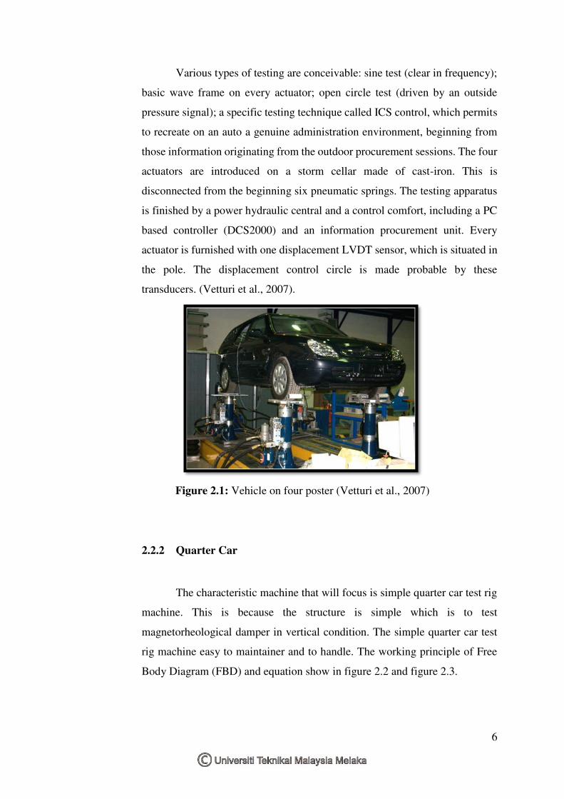
rig called four-poster, illustrates in Figure 2.1. It is constituted by four
servohydrauilic actuators all the while controlled in position, which
endorsement four vibrating plate. These can be driven by an ideal signal in the
scope of frequency 0-100 Hz. (Vetturi et al., 2007).
6
Various types of testing are conceivable: sine test (clear in frequency);
basic wave frame on every actuator; open circle test (driven by an outside
pressure signal); a specific testing technique called ICS control, which permits
to recreate on an auto a genuine administration environment, beginning from
those information originating from the outdoor procurement sessions. The four
actuators are introduced on a storm cellar made of cast-iron. This is
disconnected from the beginning six pneumatic springs. The testing apparatus
is finished by a power hydraulic central and a control comfort, including a PC
based controller (DCS2000) and an information procurement unit. Every
actuator is furnished with one displacement LVDT sensor, which is situated in
the pole. The displacement control circle is made probable by these
transducers. (Vetturi et al., 2007).
Figure 2.1: Vehicle on four poster (Vetturi et al., 2007)
2.2.2 Quarter Car
The characteristic machine that will focus is simple quarter car test rig
machine. This is because the structure is simple which is to test
magnetorheological damper in vertical condition. The simple quarter car test
rig machine easy to maintainer and to handle. The working principle of Free
Body Diagram (FBD) and equation show in figure 2.2 and figure 2.3.