Embed Size (px)
Citation preview
UNIVERSITI PUTRA MALAYSIA
STABILITY OF THIN LIQUID FILM UNDER EFFECT OF APOLAR AND ELECTROSTATIC FORCES ON
A HORIZONTAL PLANE
MOHANAD M-A. A. EL-HARBAWI
FK 2002 54
STABILITY OF THIN LIQUID FILM UNDER EFFECT OF APOLAR AND ELECTROSTATIC FORCES ON A HORIZONTAL PLANE
By
MOHANAD M-A. A. EL-HARBA WI
Thesis Submitted to the School of Graduate Studies, Universiti Putra Malaysia, in Fulfilment of the Requit"ements for Degree of Master of Science
August 2002
DEDICATED
7'0
9rty parents, 6rotliers and sisters for tlieir rear liefp
11
Abstract of thesIs presented to the Senate ofUmversltl Putra MalaysIa In fulfillment of the reqUIrement for the degree of Master of SCIence
STABILITY OF THIN LIQUID FILM UNDER EFFECT OF APOLAR AND ELECTROSTATIC FORCES ON A HORIZONTAL PLANE
By
MOHANAD M-A. A. EL-HARBA WI
August 2002
Chailman: Dr. Sa'ad Mustapha
Faculty: Engineel"ing
The understandIng of stabIlIty, dynamIcs and morphology of supported thm
«lOOnm) bqUld films and nanodrops are Important m phenomena hke flotatIon,
adhesIOn of flUId partIcles to surfaces, kmetlcs and thermodynamICS of precursor
films In wettIng, heterogeneous nucleatIOn, film boIlmg/condensatlOn, multIlayer
adsorptIon/film pressure, mstabllIty of bIOlogIcal films/membranes, and marty other
areas WhIle the wettIng of surface by large drops IS relatIvely well understood,
wettIng charactenstlcs of nanodrops and films have not been extenSIvely studIed In
some applIcatIOns lIke trIckle bed reactors, thIck coatIng, contact eqUlprtll!l1t fOl heat
and mass transfer. and the hke
Factors that would affect the total free excess energy (per wut area) of a thm
film on a substrate mclude the film thIckness, as well as the apolar and electrostatIc
spreadmg coeffiCIents for the system The dynamICS of the lIqUId film IS formulated
usmg the Navler-Stokes equatIOns augmented by a body forces descnbmg the apolar
111

and electrostatic interactions. The liquid film is assumed to be charge neutralized,
nondraining, and laterally unbounded. A modified Navier- Stokes equatIOn with
associated boundary conditions is solved using a long wave approximation method to
obtain a nonlinear equation of evolution of the film interface.
A nonlinear theory based upon the condition of infinitesimal perturbation on
the film surface is derived to obtain the growth coefficient, dominant wavelength
(i.e., wavelength corresponding to ma'Ximum growth coefficient of the surface
instability) and the film rupture time.
Solution of the nonlinear partial differential equation for a wide range of the
initial amplitude and wavelength is solved by using finite difference methods. The
calculation domain is fixed on the interval 0< X < 2,,/ A. The mesh size is taken
sufficiently small so that space and time errors are negligible. The nonlinear
algebraic equations obtamed as a result of finite difference discretization are solved
using efficient-numerical technique employing IM SL subroutine DNEQNJ.
The electrostatic force part is bigger in value than apolar, therefore it found
that it plays the dominant role in characteristics of thin films and the main effect on
the behavior of the excess free energy, growth rate, maximum growth rate, neutral
wave, dominant wavenumber, dominant wavelength and rupture time. The linear
theory may overestimate or underestimate the time of rupture by several orders of
magnitude depending upon thin film parameters. Hence linear theolY IS inadequate
to describe the stability ch ar ac ter is tics of films and therefore, the need of a nonlinear
IV
approach to the study of thin film dynamics. The calculations indicated that the
apolar and electrostatic forces can be solely responsible for the formation of flat film
of ho == 30nm in thickness. In this respect the proposed theory is consistent with the
effect of apolar and electrostatic forces on thin liquid films on a horizontal plane.
v

Abstrak tesis yang dikemukakan kepada Senat Universiti Putra Malaysia sebagai memenuhi keperluan untuk ijazah Master Sains
KESTABILAN SAPUT CECAIR NIPIS DI BAWAH KESAN DAYA APOLAR DAN ELETROSTATIK PADA SATU PERMUKAAN RATA
Oleh
MOHANAD M-A. A. EL-HARBA WI
Ogos 2002
Pengerusi: Dr. Sa'aJi Mustapha
Fakulti: Kejuruteraan
Kefahaman berkenaan kestabilan. Dinamik dan morfologi bagi cecair filem nipis
«lOOnm) dan titisan nano adalah mustahak dalam fenomena seperti perapungan,
pelekatan cecair bendalir ke permukaan, kinetik dan termodinamik penanda filem
dalam pembasahan, penukleusan heterogen, pendidihanlpemelewapan, pelbagai
lapisan penjerabanltekanan filem, ketidakstabilan filem biologilmembran, dan
banyak bidang lain. Sementara pembasahan permukaan oleh titsan besar adaIah
mudah di fahami, pencinan pembasahan titsan nano dan filem belum dikaji secara
intensif. Dalam beberapa penggunaan seperti reaktor lapisan cucur, bersalut tebal,
peralatan sentuh bagl haba dan pemindahan jisim, dan sepertinya.
Filem berkenaan adalah dimodelkan sebagai dua dimensi cecair Ne wtonian
ketumpatan tetap p dan kelikatan f.J mengalir pada satah mendatar. Cecair filem
ketebalan min ho adalah dianggap nipis cukup untuk mengabai kesan garaviti dan
VI
terhad diatas oleh satu gas dan terlanjut secara sisi ke infinit (model dua-dimensi).
Kemudian aliran seperti berikut boleh diwakili oleh satu persamaan dua-dimensi
Navier-stokes dipasangkan dengan persamaan selanjar dan keadaan sempadan
bersekutu. Sebutan daya badan dalam persamaan Navier-stokes adalah diubahsuai
dengan memasukkan saling tindak antara molekul berlebihan (apolar dan daya
elektrostatik) antara filem bendalir dan permukaan pepejal dipunyai daya apolar dan
daya elektrostatik. Persamaan Navier-Stokes terkait dengan keadaan sempadan
bersekutu adalah telah diselesaikan di bawah kaedah anggaran gelombang panjang
untuk mendapat satu persamaan tidak linear bagi filem antara muka.
Satu teori tidak linear berdasarkan atas keadaan usikan sangat kecil ke atas
permukaan filem adalah diterbitkan untuk mendapat pekali pertumbuhan, panjang
gelombang berkaitan kepada pekali pertumbuhan maksimum bagi ketidakstabilan
permukaan dan masa filem pecah.
Persamaan tidak linear bagi eolusi adalah diselesaikan secara berangka dalam
bentuk konservatif sebagai sebahagian satu masalah nilai awal bagi keadaan
sempadan berkata sempadan pada banjaran tertetap O<X < 27r/ It, dimana A adalah
satu gelombang angka. Perbezaan tertengah dalam ruang dan peraturan takat tengah
(crank-Nicholson) dalam masa digunakan. Saiz jejaring adalah diambil cukup kecil
dengan itu ralat ruang dan ralat masa diabaikan. Persamaan algebra tidak linear
diperolehi sebagai satu hasil pengdiskretan perbezaan terhingga adalah diselesaikan
menggunakan teknik berangka cekap menggunakan IMSL subroutin DNEQNJ.
Vll
Bahagian daya elektrostatik adalah lebih besar dalam nilai, apolar, dengan itu
kita dapati iaitu ia memainkan peranan penting dalam pencirian filem nipis dan kesan
utama ke atas tingkahlaku tenaga bebas berlebihan, kadar tumbuh maksimum,
gelombang neutral, gelombang nombor dominan, panjang gelombang. dominan dan
masa pecah. Teori linear mungkin terlebih anggaran atau terkurang anggaran mas a
pecah oleh beberapa tertib magnitud bergantung atas parameter filem nipis. Dengan
itu teori linear adalah tidak cukup untuk menghurai ciri kestabilan filem dan dengan
itu, keperluan satu pendekatan tidak linear kepada kajian bagi dinamik filem nipis.
Pengiraan menunjukkan daya apolar dan daya elektrostatik mungkin hanya
bertanggungjawab bagi pembentukan filem flat no ho == 30nm ketebalan. Dalam hal
ini teori cadangan adalah konsisten dengan kesan daya apolar dan daya elektrostatik
ke atas filem cecair nipis pada satu satah mendatar.
VIIl

ACKNOWLEDGEMENTS
Every praises is due to Allah alone, the Merciful and peace be upon his
prophet who is forever a torch of guidance and kno wledge for humanity as a whole.
I express my sincere gratitude to Dr. Sa'ari Mustapha for his scholarly
guidance, valuable criticism and fruitful suggestions throughout this work. His
critical revie w of the manuscript at several long sittings and assistance during thesis
writing are gratefully ackno wledged.
I am also indebted to Dr. Azni Idris and Dr. Chuah Teong Guan for theIr
generous help and guidance during the early stages of this investigation.
IX

I certify that an Examination Committee met on 22nd August' 2002 to conduct the final examination of Mohanad M-A. A. EI-Harbawi on his Master of Science thesis entitled "Stability of Thin Liquid Film Under Effect of Apolar and Electrostatic Forces on a Horizontal Plane" in accordance with Universiti Pertanian Malaysia (Higher Degree) Act 1 980 and Universiti Pertanian Malaysia (Higher Degree) Regulations 1 98 1 . The Committee recommends that the candidate be awarded the relevant degree. Members of the Examination Committee are as follows:
Sunny Iyuke, Ph.D. Faculty of Engineering Universiti Putra Malaysia (Chairman)
Sa'ari Mustapha, Ph.D. Associate Professor Faculty of Engineering Universiti Putra Malaysia (Member)
Azni Idris, Ph.D. Associate Professor Faculty of Engineering Universiti Putra Malaysia (Member)
Chuah Teong Cuan, Ph.D. Faculty of Engineering Universiti Putra Malaysia (Member)
SHAMSHER MOHAMAD RAMADILI, Ph.D. Professor/ Deputy Dean, School of Graduate Studies Universiti Putra Malaysia
Date: [r 8 OCT 2002
x
This thesis submitted to the Senate of Universiti Putra Malaysia has been accepted as fulfil lment of the requirement for the degree of Master of Science. The members of the Supervisory Committee are as fol lows:
Sa'ari Mustapha, Ph.D. Associate Professor Faculty of Engineering Universiti Putra Malaysia (Chainnan)
Azni Idris, Ph.D. Associate Professor Faculty of Engineering Universiti Putra Malaysia (Member)
Chuah Teong Guan, Ph.D. Faculty of Engineering Universiti Putra Malaysia (Member)
Xl
AINI IDERIS, Ph.D. Professor/Dean School of Graduate Studies Universiti Putra Malaysia
Date:
DECLARA TION
I hereby declare that the thesis is based on my original work except for quotation and citations, which have been duly, acknowledge. I also declare that it has not been previously or concurrently submitted for any degree at UPM or other institutions.
MOHANAD M - A. A. EL HARBA WI
Date: '2..J' 10' .2001..-
xu

DEDICATION ABSTRACT
TABLE OF CONTENTS
ABSTRAK ACKNOWLEDGEMENTS APPROVAL DECLARATION LIST OF TABLE LIST OF FIGURES LIST OF SYMBOLS
CHAPTER I INTRODUCTION
Scope of the Study Object of the Study
n LITERATURE REVIEW Applications of Thin Liquid Films In Biomedical Science Intermolecular Forces in Thin Liquid Films
Lifshitz-Van der Waals (Apolar) Forces Electrostatic Double Layer Interaction (Electrostatic Forces)
ill INSTABILITY AND MORPHOLOGY OF APOLAR AND ELECTROSTATIC FORCE The Nonlinear Equation for Dynamics of Thin Film
Hydrodynamic Model and Governing Equation Scaling of the Hydrodynamic Equations Long Wave Approximation
Component of The Surface Free Energy and Forces Due to Intermolecular Interactions
Intermolecular Forces in Thin Films Excess Free Energy for the Film Linear Stability Theory
IV NUMERICAL SOLUTION OF THE NONLINEAR EVOLUTION EQUATION
V RESULTS AND DISCCUSTION Comparison between Apolar and Electrostatic Forces Results from Linear Theory Results from Nonlinear Simulation Comparison of Prediction from Nonlinear and Linear Theories Effect of the Amplitude of Disturbance on the Rupture Depiction of the Growth of Instability (Film Profile) Time
VI CONCLUSION
Xlll
Page
U III VI IX X
XU Xlll
XVll XXll
1 4 4
6 1 6 1 9 2 1 25
32
32 32 3 5 37 44
44 49 52
53
56 56 57 59 6 1
70 74 77
VD RECOMMENDATIONS 81
REFERENCES 82 APPENDIX A 93
APPENDIX B 103 APPENDIXC 117
BIODATA OF THE AUTHOR 125
XIV
LIST OF TABLES
Table Page
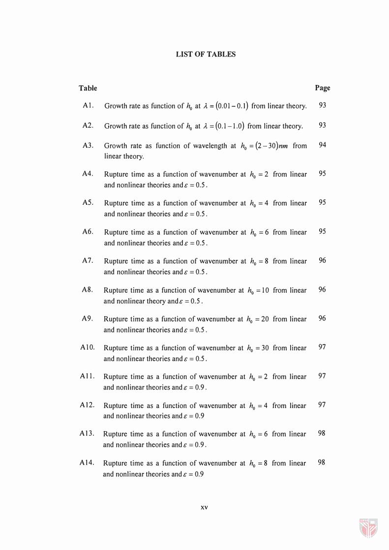
A 1. Growth rate as function of ho at A = (0.0 1- 0.1) from linear theory. 93
A2. Growth rate as function of ho at A = (0. 1 - 1 .0 ) from linear theory. 93
A3. Growth rate as function of wavelength at ho = (2 - 30 )nm from 94 linear theory.
A4. Rupture time as a function of wavenumber at ho = 2 from linear 95
and nonlinear theories and G = 0.5.
AS. Rupture time as a function of wavenumber at ho = 4 from linear 95
and nonlinear theories and G = 0.5.
A6. Rupture time as a function of wavenumber at ho = 6 from linear 95
and nonlinear theories and G = 0.5.
A 7. Rupture time as a function of wavenumber at ho = 8 from linear 96
and nonlinear theories and G = 0.5.
A8. Rupture time as a function of wavenumber at ho = 1 0 from linear 96
and nonlinear theory andG = 0.5.
A9. Rupture time as a function of wavenumber at ho = 20 from linear 96
and nonlinear theories and G = 0.5 .
AI0. Rupture time as a function of wavenumber at ho = 30 from linear 97
and nonlinear theories and G = 0.5.
A 1 1 . Rupture time as a function of wavenumber at ho = 2 from linear 97
and nonlinear theories and G = 0.9 .
A 12. Rupture time as a function of wavenumber at ho = 4 from linear 97 and nonlinear theories and G = 0.9
A13. Rupture time as a function of wavenumber at ho = 6 from linear 98
and nonlinear theories and G = 0.9.
A14. Rupture time as a function of wavenumber at ho = 8 from linear 98
and nonlinear theories and G = 0.9
xv
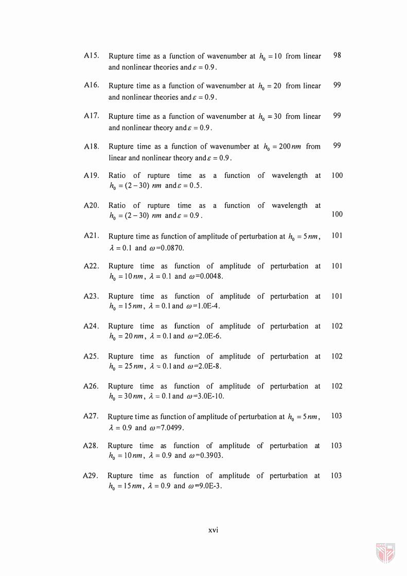
A 1 5. Rupture time as a function of wavenumber at ho = 1 0 from linear 98
and nonlinear theories and & = 0.9.
A 1 6. Rupture time as a function of wavenumber at ho = 20 from linear 99
and nonlinear theories and & = 0.9.
A 1 7. Rupture time as a function of wavenumber at ho = 30 from linear 99
and nonlinear theory and & = 0.9.
A 1 8. Rupture time as a function of wavenumber at ho = 200 nm from 99
linear and nonlinear theory and & = 0.9.
A 1 9. Ratio of rupture time as a function of wavelength at 1 00
ho = (2 - 30) nm and & = 0.5.
A20. Ratio of rupture time as a function of wavelength at
ho = (2 - 30) nm and & = 0.9 . 1 00
A2 1 . Rupture time as function of amplitude of perturbation at ho = 5 nm, 1 0 1
A = 0. 1 and m =0.0870.
A22. Rupture time as function of amplitude of perturbation at 1 0 1
ho =IOnm, A=O. 1 and m=0.0048.
A23. Rupture time as function of amplitude of perturbation at 1 0 1
ho = 1 5 nm, A = 0. 1 and m == 1 .0E-4.
A24. Rupture time as function of amplitude of perturbation at 1 02
ho = 20 nm, A = 0. 1 and m =2.0E-6.
A25. Rupture time as function of amplitude of perturbation at 1 02
ho = 25 nm, A ':: 0. 1 and m =2.0E-8.
A26. Rupture time as function of amplitude of perturbation at 1 02
ho =30nm, A=O.land m=3.0E-IO.
A2 7. Rupture time as function of amplitude of perturbation at ho = 5 nm, 103
A = 0.9 and m=7.0499.
A28. Rupture time as function of amplitude of perturbation at 1 03
ho = IOnm, A = 0.9 and m=0.3903.
A29. Rupture time as function of amplitude of perturbation at 1 03
ho = 1 5 nm, A = 0.9 and m =9.0E-3.
xvi

A30. Rupture time as function of amplitude of perturbation at 104
ho = 20nm, A. = 0.9 and w=I.OE-4.
A31. Rupture time as function of amplitude of perturbation at 104
ho = 25nm , A. = 0.9 and w=2.0E-6.
A32. Rupture time as function of amplitude of perturbation at 104
ho = 30 nm, A. = 0.9 and w =2.0E-8.
XVII

LIST OF FIGURES
Figure Page
Electrical potential distribution in an interacting double layer between 26 two identical slabs.
2 A small rectangular element in a fluid is shown. The pressure forces in 27 the z -direction act on the surface of area A . The electrical body forces are proportional to the volume (A &).
3 Schematic presentation of interfacial instability of thin fluid, 3 34 bounded by a substrate, I and a semi-infinite fluid, 2.
4 The relationship between ho and the components of free energies, 57 (�GIW & �Gll ) .
5 Growth rate as function of ho at A = (0.01- 0.1) from linear theory. 5 8
6 Growth rate as function of ho at A = (0.1-1.0) from linear theory. 5 9
7 Growth rate as function of wavelength at ho = (2 - 30 )nm from linear 60 theory.
8 A comparison of rupture times for linear and nonlinear theories as 62 functions of wavenumber, A , at ho = 2 & & = 0.5 .
9 A comparison of rupture times for linear and nonlinear theories as 63 functions of wavenumber, A, at ho = 4 & & = 0.5 .
lO A comparison of rupture times for linear and nonlinear theories as 63 functions of wavenumber, A, at ho = 6 & & = 0.5 .
11 A comparison of rupture times for linear and nonlinear theories as 64 functions of wavenumber, A, at ho = 8 & & = 0.5 .
12 A comparison of rupture times for linear and nonlinear theories as 64 functions of wavenumber, A, at ho = 10 & & = 0.5 .
13 A comparison of rupture times for linear and nonlinear theories as 65 functions of wavenumber, A, at ho = 20 & & = 0.5 .
xviii
A comparison of rupture times for linear and nonlinear theories as 65 14 functions of wavenumber, A. , at ho = 30 & C = 0.5 .
IS A comparison of rupture times for linear and nonlinear theories as 66
functions of wavenumber, A. , at ho = 200nm & C = 0.9.
16 Ratio of rupture time as function of wavelength at flo = 2nm & C = 0.5 . 6 7
17 Ratio of rupture time as function of wavelength at flo = 4nm & C = 0.5. 68
18 Ratio of rupture time as function of wavelength at ho = 6nm & C = 0.5 . 68
19 Ratio of rupture time as function of wavelength at ho = 8 nm & C = 0.5 . 69
20 Ratio of rupture time as function of wavelength at flo = I Onm & C = 0.5. 69
21 Ratio of rupture time as function of wavelength at flo = 20nm & c = 0.5 . 70
22 Ratio of rupture time as function of wavelength at ho = 30nm & c = 0.5. 70
23 Rupture time as function of amplitude of perturbation at ho = 5nm 71
and A. = 0. 1 .
24 Rupture time as function of amplitude of perturbation at ho = 10 nm 72
and A. = 0.1.
25 Rupture time as function of amplitude of perturbation at ho = 15 nm 72
and A. = 0. 1 .
26 Rupture time as function of amplitude of perturbation at ho = 20 nm 73
and A. = 0.1.
2 7 Rupture time as function of amplitude of perturbation at ho = 25 nm 73
and A. = 0.1.
28 Rupture time as function of amplitude of perturbation at ho = 30 nm 74
and A. = 0.9.
29 Film profile at different times for c = 0.5 and ho = 4 nm. The rupture 75
proceeds explosively at t n = 0.0084.
30 Film profile at different times for c = 0.5 and ho = 8 nm. The rupture 76
proceeds explosively at t n = 0.0174 .
xix

31 Film profile at different times for E = 0.5 and ho = 10 nm. The rupture 75
proceeds explosively at t n = 0.4018 .
Bl A comparison of rupture times for linear and nonlinear theories as 1 04
functions of wavenumber, A. , at ho = 2 nm & E = 0.9 .
B2 A comparison of rupture times for linear and nonlinear theories as 1 04
functions of wavenumber, A. , at ho = 4nm & E = 0.9.
B3 A comparison of rupture times for linear and nonlinear theories as 1 05
functions of wavenumber, A. , at ho = 6 nm & E = 0.9.
B4 A comparison of rupture times for linear and nonlinear theories as 1 05
functions of wavenumber, A. , at ho = 8nm & E = 0.9 .
B5 A comparison of rupture times for linear and nonlinear theories as 1 06
functions of wavenumber, A. , at ho = 1 0 nm & E = 0.9.
B6 A comparison of rupture times for linear and nonlinear theories as 1 06
functions of wavenumber, A. , at ho = 20 nm & E = 0.9 .
B7 A comparison of rupture times for linear and nonlinear theories as 1 07
functions of wavenumber, A. , at ho = 30 nm & E = 0.9.
B8 Ratio of rupture time as function of wavelength at ho = 2nm & E = 0.9 1 08
B9 Ratio of rupture time as function of wavelength at ho = 4nm & E = 0.9 1 08
BI0 Ratio of rupture time as function of wavelength at ho = 6nm & E = 0.9. 109
B 1 1 Ratio of rupture time as function of wavelength at ho = 8 nm & E = 0.9 . 109
B 1 2 Ratio of rupture time as function of wavelength at ho = 1 Onm & E = 0.9 . 1 1 0
B 1 3 Ratio of rupture time as function of wavelength at ho = 20nm & E = 0.9 . 110
B 1 4 Ratio of rupture time as function of wavelength at ho = 30nm & E = 0.9. 1 1 1
B IS Rupture time as function of amplitude of perturbation at ho = 5 nm 1 1 2
and A. = 0.1.
B 1 6 Rupture time as function of amplitude of perturbation at ho = 1 0 nm 1 1 2
and A. = 0.1.
xx

B17 Rupture time as function of amplitude of perturbation at ho = 15 nm 113
and A = 0.1. B18 Rupture time as function of amplitude of perturbation at ho = 20 nm 113
and A = 0.1. B19 Rupture time as function of amplitude of perturbation at ho = 25 nm
114
and A = 0.1.
B20 Rupture time as function of amplitude of perturbation at ho = 30nm 114
and A = 0.1.
B2l Film profile at different times for & = 0.9 and ho = 4 nm. The rupture 115
proceeds explosively at t n = 0.001 and n = 21 .
B22 Film profile at different times for & = 0.9 and ho = 10 nm. The rupture 115
proceeds explosively at In = 0.0316 and n = 21.
B23 Film profile at different times fore = 0.9 and ho = 20nm. The rupture 116
proceeds explosively at I" = 50.8125 and n = 21.
B24 Film profile at different times for & = 0.9 and ho = 4 nm . The rupture 116
proceeds explosively at In = 0.0099 and n = 41 .
B25 Film profile at different times for & = 0.9 and ho = 10 nm . The rupture 117
proceeds explosively at tn = 0.0312 and n = 41.
B26 Film profile at different times for & = 0.9 and ho = 4 nm. The rupture 117
proceeds explosively at In = 50.8110 and n = 41.
xxi
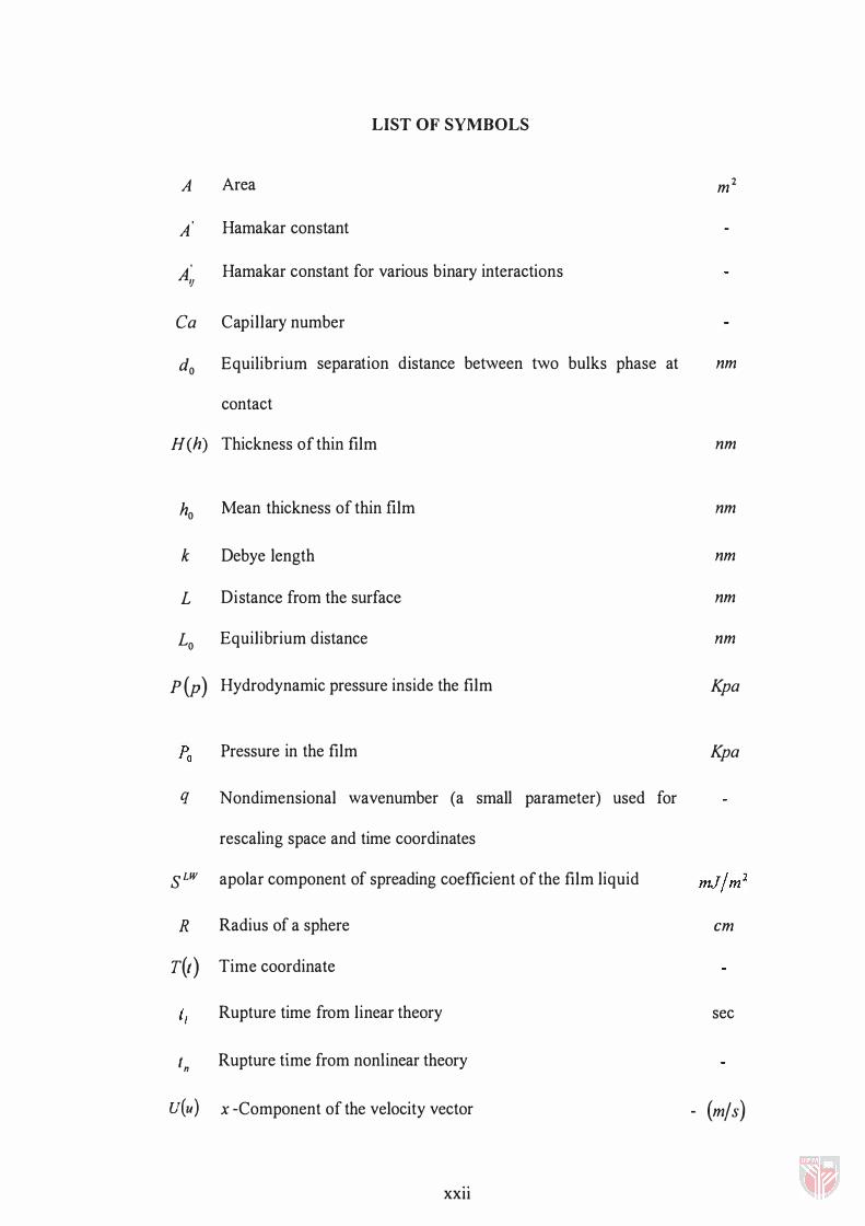
LIST OF SYMBOLS
A Area
A Hamakar constant
A� Hamakar constant for various binary interactions
Ca Capillary number
do Equilibrium separation distance between two bulks phase at
contact
H(h) Thickness of thin film
ho Mean thickness of thin film
k Debye length
L Distance from the surface
Lo Equilibrium distance
p (p) Hydrodynamic pressure inside the film
D Pressure in the film La
q Nondimensional wavenumber (a small parameter) used for
rescaling space and time coordinates
S LW apolar component of spreading coefficient of the film liquid
R Radius of a sphere
T(t) Time coordinate
Rupture time from linear theory
t n Rupture time from nonlinear theory
U(u) x -Component of the velocity vector
XXll
m2
nm
nm
nm
nm
nm
nm
Kpa
Kpa
em
sec
- (mj s)
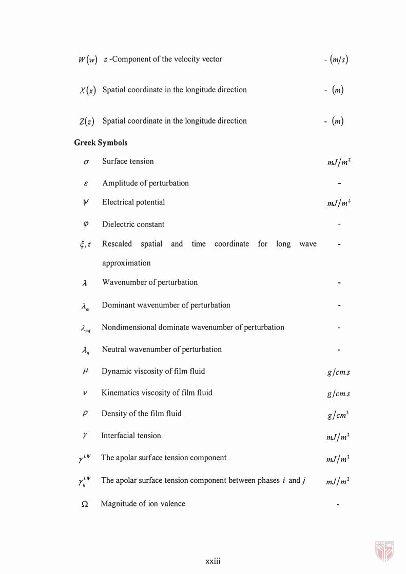
W(w) z -Component of the velocity vector
X(x) Spatial coordinate in the longitude direction
Z(z) Spatial coordinate in the longitude direction
Greek Symbols
Surface tension
G Amplitude of perturbation
Electrical potential
cP Dielectric constant
;, T Rescaled spatial and time coordinate for long wave
approximation
A Wavenumber of perturbation
1 Dominant wavenumber of perturbation Am
1 Nondimensional dominate wavenumber of perturbation Ami
An Neutral wavenumber of perturbation
fJ Dynamic viscosity of film fluid
v Kinematics viscosity of film fluid
P Density of the film fluid
y Interfacial tension
yLW The apolar surface tension component
yLW Ij The apolar surface tension component between phases i and j
n Magnitude of ion valence
xx III
- (m/ s)
- (m)
- (m)
g/cm.s g/cm.s g/cm3
mf/m2 mf/m2 mf/m2
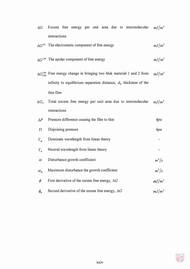
llG Excess free energy per unit area due to intermolecular mJ / m2 interactions
llG HI. The electrostatic component of free energy mJ / m 2
llG"W The apolar component of free energy mJ / m2
llGLW Free energy change in bringing two bluk material 1 and 2 from mJ/m2 132C infinity to equilibrium separation distance, do thickness of the
thin film
llGr Total excess free energy per unit area due to intermolecular mJ / m2 interactions
M Pressure difference causing the film to thin
n Disjoining pressure
r m Dominate wavelength from linear theory
rn Neutral wavelength from linear theory
OJ Disturbance growth coefficient
OJm Maximum disturbance the growth coefficient
¢ First derivative of the excess free energy, I1G
¢h Second derivative of the excess free energy, llG
XXIV
kpa
kpa