Embed Size (px)
Citation preview

1ST PRINTING OCTOBER ‘02
MANUAL NO. 999-1517
SEGA ENTERPRISES, INC. USA
www.seuservice.com
Universal KitKit Installation Instructions
& Service Manual
Switchable FROM High Resolution 31K TO Standard (Low) Resolution 15.75K.
1 - 2 PLAYER GAME

VISIT OUR WEBSITE!
PRODUCTION DATE This Product was produced in the year of: 2002

BEFORE USING THE PRODUCT, BE SURE TO READ THE FOLLOWING:To maintain the safety:
To ensure the safe usage of the product, be sure to read the following before using the product. The following instructions are intended for the users, operators and the personnel in charge of the opera-tion of the product. After carefully reading and sufficiently understanding the warning displays and cautions, handle the product appropriately. Be sure to keep this manual nearby the product or else-where convenient for referring to it when necessary.
Herein, explanations which require special attention are enclosed with dual lines. Depending on the potentially hazardous degrees, the terms of WARNING, CAUTION, etc. are used. Be sure to under-stand the contents of the displays before reading the text.
Indicates that mishandling the prod-uct by disregarding this warning will cause a potentially hazardous situation which can result in death or serious injury.
Indicates that mishandling the product by disregarding this caution will cause a slight hazardous situation which can result in personal injury and or material damage.
For the safe usage of the product, the following pictographs are used:
Indicates “HANDLE WITH CARE.” In order to protect the human body an equipment, this display is attached to places where the Owner’s Manual and or Service Manual should be referred to.
Perform work in accordance with the instructions herein stated.Instructions for work are explained by paying attention to the aspect of accident prevention. Failing to perform work as per the instructions can cause accidents. In the case where only those who have tech-nical expertise should perform the work to avoid hazardous situation, the instructions herein state that the serviceman should perform such work.
Be sure to turn off power before working on the machine.To prevent electric shock, be sure to turn off power before starting the work in which the worker touches the interior of the product. If the work is to be performed in the power-on status, the Instruction Manual herein always states to that effect.
Be sure to ground the Earth Terminal (this, however, is not required in the case where a power cord with earth is used).This product is equipped with the Earth Terminal. When installing the product, Connect the Earth Ter-minal to the “accurately grounded indoor earth terminal” by using an earth wire. Unless the product is grounded appropriately, the user can be subject to electric shock. After performing repair, etc. for the Control equipment, ensure that the Earth Wire is firmly connected to the Control equipment.
Ensure that the Power Supply used is equipped with an Earth Leakage Breaker.This product does not incorporate the Earth Leakage Breaker. Using a power supply which is not equipped with the Earth Leakage Breaker can cause a fire when earth leakage occurs.
Be sure to use fuses which meet the specified rating. (only for the machines which use fuses).Using fuses exceeding the specified rating can cause a fire and electric shock.
WARNING! CAUTION!

Specification changes (removal of equipment, conversion and addition) not designated by SEGA are not allowed.The parts of the product include warning labels for safety, covers for personal protection, etc. It is very hazardous to operate the product by removing parts and or modifying the circuits. Should doors, lids and protective parts be damaged or lost, refrain from operating the product, and contact where the product was purchased from or the office herein stated. SEGA shall not be held responsible for any accidents, compensation for damage to a third party, resulting from the specifications not designated by SEGA.Ensure that the product meets the requirements of appropriate Electrical Specifications.Before installing the product, check for Electrical Specifications. SEGA products have a nameplate on which Electrical Specifications are described. Ensure that the product is compatible with the power supply voltage and frequency requirements of the location. Using any Electrical Specifications different from the designated Specifications can cause a fire and electric shock.Install and operate the product in places where appropriate lighting is available, allowing warning labels to be clearly read.To ensure safety for the customers, labels and printed instructions describing potentially hazardous situ-ation are applied to places where accidents can be caused. Ensure that where the product is operated has sufficient lighting allowing the warnings to be read. If any label is peeled off, apply it again imme-diately. Please place an order with where the product was purchased from or the office herein stated.When handling the Monitor, be very careful. (Applies only to the product w/monitor.)Some of the monitor (TV) parts are subject to high tension voltage. Even after running off power, some portions are still subject to high tension voltage sometimes. Monitor repair and replacement should be performed only be those technical personnel who have knowledge of electricity and technical expertise.Be sure to adjust the monitor (projector) properly. (Applies only to the product w/monitor.)Do not operate the product leaving on-screen flickering or blurring as it is. Using the product with the monitor not properly adjusted may cause dizziness or a headache to an operator, a player, or the cus-tomers.When transporting or reselling this product, be sure to attach this manual to the product.In the case where commercially available monitors and printers are used in this product, only the con-tents relating to this product are explained herein. Some commercially available equipment has func-tions and reactions not stated in this manual. Read this manual together with the specific Instruction Manual of such equipment.
Descriptions herein contained may be subject to improvement changes without notice.The contents described herein are fully prepared with due care. However, should any question arise or errors be found, please contact SEGA.
••
INSPECTIONS IMMEDIATELY AFTER TRANSPORTING THE PRODUCT TO THE LOCATION.
Normally, at the time of shipment, SEGA products are in a status allowing for usage immediately after transporting to the location. Nevertheless, an irregular situation may occur during transportation. Before turning on power, check the following points to ensure that the product has been transported in a satis-factory status.Are there any dented portions or defects (cuts, etc.) on the external surfaces of the cabinet?Are Casters and Adjusters, damaged?Do the power supply voltage and frequency requirements meet with those of the location?Are all wiring connectors correctly and securely connected? Unless connected in the correct direction, connector connections can not be made accurately. Do not insert connectors forcibly.Do power cords have cuts and dents?Do the fuses used meet specified rating? Is the Circuit Protector in an energized status?Are all accessories available?Can all Doors and Lids be opened with the Accessory keys? Can Doors and Lids be firmly closed?

1 www.seuservice.com
Virtua Fighter 4 Evolution Sega Naomi 2 System
Kit Contains List
Part #
840-0106D-01
400-5397-01
560-5407-UL
600-7009-2500
600-7141-250
600-7158-0100
838-13616
838-13683-02
999-1518
999-1519
999-1520
999-1521
421-7988-91
999-1517
999-1515
Desc
ASSY CASE NET VF4EV USA
SW REGU FOR JVS
TRANSFORMER, 120V 17V2A
RGB CABLE
CABLE JVS TYPE A-B 250CM
CA AUDIO RCA TO RCA 2CH
AUDIO POWER AMP
JAMMA I/O BD
MARQUEE ART
INSTRUCTION SHEET
DECAL SIDE ART
CONTROL PANEL
STICKER SERIAL NUMBER
KIT MANUAL -VF4 EVOLUTION
INST. SHEET PLAYER
Qty
1
1
1
1
1
1
1
1
1
1
2
1
1
1
1
Parts not supplied in kit, but required for operation.
6vdc Coin Meter
Test Switch
Service Switch
5k Pot (for Volume Control)
8way JoyStick
SPST Momentary Switch (Start )
SPST Momentary Switch (Punch)
SPST Momentary Switch (Kick)
SPST Momentary Switch (Defence)
VGA or NTSC RGB Monitor
1
1
1
1
2
2
2
2
2
1
Suggested Happ # Desc Qty42-2093-00
50-7608-XX
58-9111-LXPLY
58-91XX-L
58-91XX-L
58-91XX-L

2www.seuservice.com 3 www.seuservice.com
DESIGNED RELATED PARTS
MARQUEE ART
999-1518
CTRL PNL OVERLAY
999-1521

2www.seuservice.com 3 www.seuservice.com
SIDE ART
999-1520
INSTR. SHEET (moves)
999-1519
INSTR. SHEET (player)
999-1515
4www.seuservice.com 5 www.seuservice.com
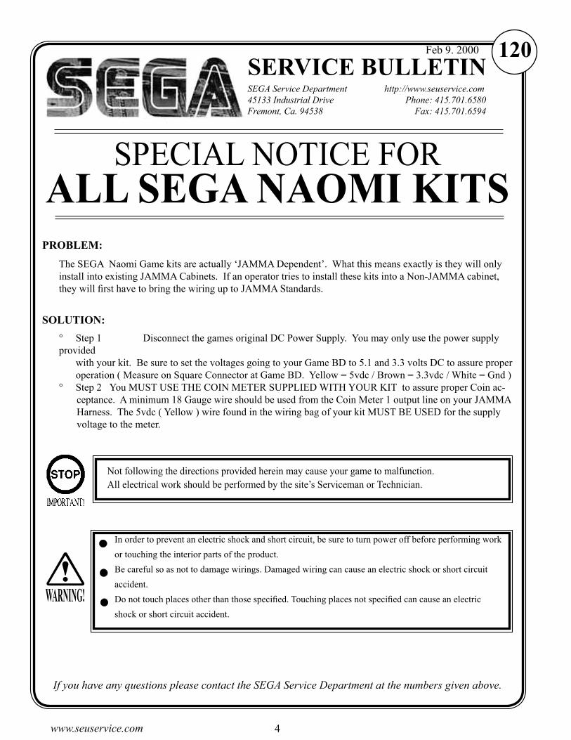
SERVICE BULLETINSEGA Service Department http://www.seuservice.com45133 Industrial Drive Phone: 415.701.6580Fremont, Ca. 94538 Fax: 415.701.6594
If you have any questions please contact the SEGA Service Department at the numbers given above.
120Feb 9. 2000
The SEGA Naomi Game kits are actually ‘JAMMA Dependent’. What this means exactly is they will only install into existing JAMMA Cabinets. If an operator tries to install these kits into a Non-JAMMA cabinet, they will first have to bring the wiring up to JAMMA Standards.
° Step 1 Disconnect the games original DC Power Supply. You may only use the power supply provided with your kit. Be sure to set the voltages going to your Game BD to 5.1 and 3.3 volts DC to assure proper operation ( Measure on Square Connector at Game BD. Yellow = 5vdc / Brown = 3.3vdc / White = Gnd )° Step 2 You MUST USE THE COIN METER SUPPLIED WITH YOUR KIT to assure proper Coin ac-
ceptance. A minimum 18 Gauge wire should be used from the Coin Meter 1 output line on your JAMMA Harness. The 5vdc ( Yellow ) wire found in the wiring bag of your kit MUST BE USED for the supply voltage to the meter.
SPECIAL NOTICE FOR ALL SEGA NAOMI KITS
PROBLEM:
SOLUTION:
Not following the directions provided herein may cause your game to malfunction.All electrical work should be performed by the site’s Serviceman or Technician.
In order to prevent an electric shock and short circuit, be sure to turn power off before performing work
or touching the interior parts of the product.
Be careful so as not to damage wirings. Damaged wiring can cause an electric shock or short circuit
accident.
Do not touch places other than those specified. Touching places not specified can cause an electric
shock or short circuit accident.
WARNING!

4www.seuservice.com 5 www.seuservice.com
INSTALLATION INSTRUCTIONS1) Turn off power and unplug machine. Open all access panels. Locate the original game
Power Supply, Game BD, I/O BD, Sound BD etc… Remove these items from your cabinet. Remove all artwork from cabinet. Clean Cabinet Exterior and repair as necessary to assure good appearance.
2) Remove all existing harnesses. Install a new JAMMA Harness (Recommended). Please note that this harness is NOT SUPPLIED with your kit. DO NOT connect the 5vdc, 12vdc, GND or any other power line from the JAMMA Harness to the Power Supply. Note: If you are using a VGA compatible monitor you can run your VGA cable directly to the monitor or connect it to your JVS JAMMA interface for RGB conversion to your JAMMA cables.
3) Install the Components supplied in your kit (Game BD, Power Supply, Amp, Transformer etc.). Follow the wiring diagram for proper electrical connection (located at the end of the kit manual). Be careful to fasten all components securely. Route wires in a manner not to allow for pinching or binding. Secure wires once connected.
Vacuum out or clean bottom of cabinet of dirt & miscellaneous parts (e.g. screws, loose coins / tokens, etc.).
Remove all exterior decals and repair any cabinet damage. Repaint cabinet if necessary. Remove the Monitor Plexi or if your game plexi has Silk-screened artwork, you will need to strip it off.
4) Connect your cabinet’s existing Service Switch Bracket Assy to the Kit Harness (Follow Diagram). Please note that you MUST USE a COIN METER for the game system to properly accept coins (Refer to Diagrams and Service Bulletin included in this manual).
5) Remove all Joystick Buttons and Pushbuttons from your Control Panel. Remove the existing overlay. Clean off all glue residues, and fill in or plug existing holes to give you a blank work area for your new game.
6) Install your Control Panel Art supplied with the kit. Cut holes in the overlay where controls are to be installed. Install and connect your controls. Please note that Joysticks and Pushbuttons are NOT SUPPLIED with your kit. You will need to supply 2ea 8way Joysticks, 2ea Start Buttons, and 2ea Punch, Kick and Defense buttons.
7) Connect your Coin Switches to the game harness following the diagram in the back of the manual.
8) Turn on Power to the game and check for proper voltages on either connector entering the Game BD Filter BD. The proper voltages are: 5.1vdc between Yellow and White, 3.30vdc between Brown and White. Adjust where necessary. Adjustment can be made at the Power Supply by using an insulated flat screwdriver. Turn clockwise to increase. Turn counter-clockwise to decrease.

6www.seuservice.com 7 www.seuservice.com
INSTALLATION INSTRUCTIONS
9) Finish installation by installing Side Decals, Marquee and any instruction decals. Play your machine to verify proper operation. Set up options as desired.
Adjust the SIZE, CONTRAST, BRIGHTNESS, and COLORS on the Monitor for optimum appearance. Adjust VERTICAL/HORIZONTAL Hold to get a stable picture, if required.
Enter DIAGNOSTICS and adjust the Volume Level, test all Buttons & Joystick for proper operation & wiring. Adjust Pricing. Coin-Up and test out a game to ensure proper play functions are as they should be.

6www.seuservice.com 7 www.seuservice.com
Sega Naomi System Switch Bracket and Speaker Installation Diagrams
(Figure 3)
Coin Meter
Test Service
Volume JAMMA Pin R
JAMMA Pin 15JAMMA Pin 1
Yellow Wire from ExtraHarness (+5v)
JAMMA Pin 8
+_
Pin 1
Pin 5
Pin 4
To CN1 ofAmplifier Board
YE
L/R
ED
WH
T/R
ED
GR
N/R
ED
From CN2 ofAmplifier Board
From CN4 ofAmplifier Board
GRY/RED
ORG/RED
ORG/BLUE
GRY/BLUE
LeftSpeaker
RightSpeaker

8www.seuservice.com 9 www.seuservice.com
Sega Naomi System JAMMA Harness Wiring
(JAMMA I/O BD) (Figure 4)
4
1
2
3
5
6
7
8
10
11
12
13
14
15
16
17
18
19
20
21
A
B
C
D
E
F
H
J
K
L
M
N
P
R
S
T
U
V
X
Y
Z
a
22
23
24
4
e
d26
25 c
b
28 f
27
9
W
Ground
Ground
Ground
Ground
+5v (Not Used) +5v (Not Used)
+5v (Not Used) +5v (Not Used)
(Not Used) (Not Used)
+12v (Not Used) +12v (Not Used)
Key Key
Coin Meter 1 Coin Meter 2
(Not Used)
(Not Used)
(Not Used)
(Not Used)
(Not Used)
(Not Used)
Video Red
Video Blue
Video Ground
Video Green
Video Sync
Service
Test (Not Used)
Coin 1 Coin 2
1P Start 2P Start
1P UP 2P UP
2P Down1P Down
1P Left 2P Left
1P Right
Attack 1P (1P SW1)
Grapple 1P (1P SW2)
Support 1P (1P SW3)
Ground
Ground
2P Right
Attack 2P (2P SW1)
Ground
Ground
Support 2P (2P SW3)
Grapple 2P (2P SW2)
(Not Used)
(Not Used)
(Not Used)
(Not Used)

8www.seuservice.com 9 www.seuservice.com
CN4
Sega Naomi SystemFilter Board Information
Connector Description etc.
PSW2 PSW1
CN3CN2 CN1
DIPSW1
Power ConnectorsVGA LevelVideo Out
Preamp LevelAudio Out
Test Switch
ServiceSwitch
1
1
2
2
3
3
4
Setting for HighResolution 31KHZ1 -4 off
Setting for StandardResolution 15KHZ1 on 2-4 off.

10www.seuservice.com 11 www.seuservice.com
To prevent electric shock or IC Board malfunctioning, be sure to turn off the power for the cabinet when installing or removing the IC Board.
Extraneous matter such as dust on the IC Board can cause the IC Board to generate heat and result in a fire due to short circuit, etc. Ensure the IC Board surfaces are always kept clean.
Use NAOMI 2 for the cabinets compatible with JVS. Using NAOMI for the cabinet other than those compatible with JVS can cause generation of heat and a fire.
Be sure to connect the IC Board and connectors completely. Insufficient insertion can damage IC Board, etc.
For the IC Board circuit inspection, only the use of Logic Tester is permitted.The use of ordinary testers is not permitted as these can damage the IC Board.
Do not subject the IC Board to static electricity when installing the IC Board in the cabinet or when connecting wire harness connectors to the IC Board.
When soldering buttons, etc. to the wire harnesses, be sure to remove the wire harnesses from the IC Board so as not to subject the IC Board to heat.
Using NAOMI 2 without the Shield Case can cause electric wave trouble. Be sure to use NAOMI 2 together with the accessory Shield Case.
The monitor frequency corresponding to NAOMI 2 is 15 kHz or 31 kHz.NAOMI 2 can not be used for the cabinet incorporating a monitor or projector not corresponding to 15 kHz or 31 kHz.
1. HANDLING PRECAUTIONS
Concerning the display of JAMMA VIDEO STANDARD: JAMMA VIDEO STANDARD adopted by NAOMI 2 is referred to as JVS. As against this
Standard, the conventional JAMMA STANDARD which employs 56P Edge Connectors adopted by ST-V, etc. is displayed as Old JAMMA STANDARD.
The specific Manual attached to each game sometimes displays JVS as JV STANDARD, New JAMMA STANDARD, or JAMMA 2 STANDARD against OLD JAMMA STANDARD as JAMMA STANDARD, JS, etc.
The contents herein described are subject to change without notice.
STOPIMPORTANT!
WARNING!

10www.seuservice.com 11 www.seuservice.com
2. SPECIFICATIONS
ON-SCREEN DISPLAY
Monitor Position
Horizontal Synchronous Frequency31/15 kHz
CONTROL PANEL
HORIZONTAL
START
DEFENSE (GUARD)
PUNCH
KICK8WAYS

12www.seuservice.com 13 www.seuservice.com
3 - 1 OUTLINE OF THE GAME
You, as a martial art fighter, play in a tournament.
For one-person match, you operate a playing character to fight against an opponent computer-operated character (CPU).
For person-vs-person match, two players operate each playing character to fight against each other.
The playing characters covers 15 selectable regular characters and 1 boss character.
3 - 2 PLAYING PROCEDURE
Total 15 characters are available. Out of them you select one character to start the game.
At each stage you play a match against a computer-operated character.
Winning a match• Each match consists of multiple rounds. You win a match when the number of your gained
rounds reaches a preset value.• When you win a match at any stage, you can proceed to a next stage and play a match against
a new computer-operated character.
Gaining a round You can gain a round when either of the following events occurs.
• You successfully reduce the opponent's energy to 0 (zero).• Your energy remains much more than the opponent's energy when the limit time has become
0 (zero).• You turn the opponent out of the ring.When you and the opponent have drawn (that is, at the end of a round, both have a same level of energy or have knocked each other at the same time), both can gain the round exceptionally.When you and the opponent have drawn under a sudden death state (that is, the number of the gained rounds is equal to each other and either can win the match by obtaining one more round), either with more energy becomes a winner of the match.
When the GAME becomes OVER The game is over when either of the following events occurs.
• You lose a match against a computer-operated character.• You finish all the 11 stages: 10 stages, each with a regular computer-operated character, and 1
stage with a boss computer-operated character.
Continuing the game You can continue the game as follows.
• When you lose a match, the CONTINUE screen appears.• Insert the credit coins before the limit time is counted down to 0 (zero) on the CONTINUE
screen, and press the start button. Then, you can continue the game (or resume the first round of the stage where you lost a match).
3. GAME DESCRIPTION

12www.seuservice.com 13 www.seuservice.com
3 - 3 CHARACTER SELECT SCREEN
You select one out of the 15 available characters.
Each character indicates its name, figure and profile.
Place the lever in an upper, lower, left, or right position to migrate from character to character, and press either of the punch, kick, and defense buttons to select a character.
Hold down the start button and press either of the punch, kick, and defense buttons to toggle between 1P character's color and 2P character's color.
3 - 4 GAME-PLAYING SCREEN

14www.seuservice.com 15 www.seuservice.com
3 - 5 BASIC OPERATIONS OF THE CONTROLS
The following explains the operation for a 1P character. For a 2P character, read right and left reverse.
The following abbreviations are used herein.
P: Punch button
K: Kick button
G: Defense (Guard) button
+: Operating the two or more controls at the same time
• P: Punching attack
• K: Kicking attack
• G: Defending upper and middle parts
• Lever in a lower position + G: Defending lower part (Note: The opponent may attack you at your upper, middle, or lower part. You must defend
your upper, middle, or lower part accordingly.)
• Lever in a right position: Moving forwards
• Lever in a left position: Moving backwards
• Lever in an upper position instantly: Dodging away from you
• Lever in a lower position instantly: Dodging toward you
• P or K + lever in an upper position: Jumping upwards
• P or K + lever in an upper right position: Jumping diagonally forwards
• P or K + lever in an upper left position: Jumping diagonally backwards
• Lever in a right position two times quickly: Dashing forwards
• Lever in a left position two times quickly: Dashing backwards
• Lever in a lower right position two times quickly: Crouching and dashing forwards
• Lever in a lower left position: two times quickly: Crouching and dashing backwards
• Lever held in a lower position: Crouching
• P + G when you are close to the opponent: Throwing
• P + G when the opponent is throwing you: Escaping the throw (slipping)
• Lever in an upper position + P for the downed opponent: Jumping and attacking the downed opponent
• Repeated G when you are downed: Standing up quickly
• Repeated K when you are downed: Kicking attack immediately after quickly standing up
• Lever in a left position + repeated G when you are downed: Rolling backwards and standing up
• Lever in an upper/down position + repeated G when you are downed: Rolling left/right and standing up
• Continuously operated lever in a left/right position when you are faltering: Unfaltering quickly
14www.seuservice.com 15 www.seuservice.com
3 - 6 SPECIAL OPERATIONS OF THE CONTROLS
Dodging/AttackingImmediately after surely dodging by a lever operation, you attack an opponent. Thus you can use the combination of dodging/attacking skills.
Lever in an upper position instantly + P + K + G: Dodging away from you and attackingLever in a lower position instantly + P + K + G: Dodging toward you and attacking
Recovery (Ukemi = safe ways of falling down)The ukemi enables you to regain your balance just when landing and to immediately attack an opponent. This skill lessens damage to you. Thus you can escape from the crunch and rather earn a chance to counterattack. You may be just downed or use the ukemi, whichever is tactically desirable in each situation.
P + K + G immediately before you are downed: Ukemi
Charge Attack (attacking with the accumulated energy)Using the energy accumulated for a little time, you can destroy an opponent's defenses. This high-risk, high-return skill enhances your tactical capabilities. Special commands, one each with a character, are available to activate this function.
Fighting by the walls• You may damage and destroy the walls. Thereby you can change the state of the ring as
tactically required.• The opponent may falter when you throw him/her against the walls. This enables you to use
the combination (Combo) skills.

16www.seuservice.com 17 www.seuservice.com
3 - 7 PERSON-VS-PERSON (VS) MATCHS
• A new player may join you in playing the GAME or selecting a character. As a result the system suspends the current one-person match against a computer-operated character and starts a person-vs-person match.
• The new player must insert the credit coins before joining.
• After playing the person-vs-person match only the winner can continue to play the suspended match: one-person match against a computer-operated character. He/she resumes the first round of the suspended match.
PERSON-VS-PERSON (VS) MATCHS • CHARACTER SELECT SCREEN
• When you have set the STAGE item to RANDOM on the GAME ASSIGNMENTS screen, the built-in computer (CPU) randomly selects a stage.
• When you have set the STAGE item to SELECTIVE on the GAME ASSIGNMENTS screen, the newly joined player selects a stage. (For more information see the chapter 4, B, b. "GAME ASSIGNMENTS.") To select, he/she places the lever in an upper, lower, left, or right position to migrate from stage to stage, and presses either of the punch, kick, and defense buttons.
PERSON-VS-PERSON (VS) MATCHS • STAGE SELECT SCREEN

16www.seuservice.com 17 www.seuservice.com
4. TEST MODEA. SYSTEM MENU
When settings are changed in SYSTEM ASSIGNMENTS, COIN ASSIGNMENTS, and GAME ASSIGNMENTS of GAME TEST MODE, be sure to exit from the test mode of SYSTEM MENU screen. The contents of setting changes are stored in the IC on the BOARD when exiting from the Test Mode. If the power is turned off in the Test Mode (before exiting), the contents of setting changes are ineffective. In this case, the settings remain unchanged.
This test mode mainly allows the IC Board to be checked for accurate functioning, monitor color to be adjusted as well as COIN ASSIGNMENTS and GAME ASSIGNMENTS to be adjusted.
1) Connect the power, and press the TEST Button. Then the following SYSTEM MENU screen appears.
SYSTEM MENU
RAM TEST JVS TEST SOUND TEST C.R.T. TEST SYSTEM ASSIGNMENTS COIN ASSIGNMENTS BOOKKEEPING BACKUP DATA CLEAR CLOCK SETTING
ROM BOARD TEST GAME TEST MODE [XXXXXXXXX ]
-> EXIT
SELECT WITH SERVICE BUTTON AND PRESS TEST BUTTON
For the SYSTEM ASSIGNMENTS, do notchange the following default settings: CABINET TYPE: 2 PLAYER(S)MONITOR TYPE: HORIZONTALSERVICE TYPE: COMMON
For the COIN ASSIGNMENTS, set as follows:COIN CHUTE TYPE: COMMONCOIN/CREDIT SETTING: at discretionSEQUENCE: at discretion
Out of the COIN ASSIGNMENTS items, the SEQUENCE # items means as follows: SEQUENCE 1: The number of credits required for starting the gameSEQUENCE 2: The number of credits required for continuing the gameSEQUENCE 3 to 8: Not Used
BOOKKEEPING 2/2 means as follows:P1 SEQ 1: Play frequency of Player 1P2 SEQ 2: Frequency of CONTINUE by Player 1P3 SEQ 3-8: Not Used
2) Press the SERVICE Button to move the -> mark to any desired item, and press the TEST Button.
3) Press the SERVICE Button to move the -> mark to GAME TEST MODE item, and press the TEST Button. Then the GAME TEST MENU screen appears that enables to test the items specific to this game. For the details, see the following pages.
4) After testing, select the EXIT and press the TEST Button. The game advertising screen reappears.
NOTE: For more information about the SYSTEM MENU screen, see the NAOMI 2 Service Manual.
STOPIMPORTANT!

18www.seuservice.com 19 www.seuservice.com
B. GAME TEST MODE
Press the SERVICE Button to move the arrow mark to the GAME TEST MODE item on the SYSTEM MENU screen, and press the TEST Button. The GAME TEST MENU screen, specific for this game, opens. Press the SERVICE Button to move the arrow mark to a desired test item on the GAME TEST MENU screen, and press the TEST Button to open the related screen.After testing, move the arrow mark to the EXIT item and press the TEST Button. The SYSTEM MENU screen reappears
VF4 EVOLUTION GAME TEST MENU
-> INPUT TEST GAME ASSIGNMENTS 1P ARRIVAL STAGE CHARA DATA TOTAL DATA VS DIAGRAM GAME BOOKKEEPING BACKUP DATA CLEAR
EXIT
SELECT WITH SERVICE BUTTON AND PRESS TEST BUTTON
GAME TEST MENU Screen

18www.seuservice.com 19 www.seuservice.com
INPUT TEST
PLAYER 1P 2P
START OFF OFF UP OFF OFF DOWN OFF OFF LEFT OFF OFF RIGHT OFF OFF
GUARD OFF OFF PUNCH OFF OFF KICK OFF OFF TEST OFF SERVICE OFF
PRESS SERVICE+TEST BUTTON TO EXIT
START
DEFENSE (GUARD)
PUNCH
KICKUP
RIGHTLEFT
DOWN
a. INPUT TEST
INPUT TEST Screen
CONTROL PANEL
This test displays the state of each switch and button.If the switch goes ON when the switch/button is pressed, it is satisfactory.Press SERVICE Button and TEST Button simultaneously to have the MENU return on to the screen.

20www.seuservice.com 21 www.seuservice.com
b. GAME ASSIGNMENTS
Allows game difficulty adjustments, time setting, etc. to be changed. Move the arrow to the desired item by SERVICE Button and press the TEST Button to change the setting. Select EXIT to return to the MENU screen.
GAME ASSIGNMENTS Screen
GAME ASSIGNMENTS
ENEMY LEVEL NORMAL ENERGY MAX(1P) 200 ENERGY MAX(VS) 200 MATCH COUNT(1P) 2 MATCH COUNT(VS) 2 TIME LIMIT 30
STAGE SELECT RANDOM CONTINUE ON VS FINISH OFF
RETURN TO DEFAULT SETTING -> EXIT
SELECT WITH SERVICE BUTTON AND PRESS TEST BUTTON

20www.seuservice.com 21 www.seuservice.com
ENEMY LEVEL: Sets the difficulty level of the one-person match. VERY EASYEASYNORMALHARDVERY HARD (De-
fault: NORMAL)
ENERGY MAX (1P): Sets the energy (initial value) in a one-person game. 180200220240 (Default: 200)
ENERGY MAX (VS): Sets the energy (initial value) in a person-vs-person game. 180200220240 (Default: 200)
MATCH COUNT (1P): Sets the number of the rounds that a player aims to gain for winning the related match in a one-person game.
2345 (Default: 2)
MATCH COUNT (VS): Sets the number of the rounds that a player aims to gain for winning the related match in a person-vs-person game.
2345 (Default: 2)
TIME LIMIT: Sets the limit time of a match. 304560 (Default: 30)
STAGE SELECT: Sets the method of selecting a stage in a person-vs-person game. RANDOM indicates an automatic selection by the computer. RANDOMSELECTIVE (Default: RANDOM)
CONTINUE: Determines whether you can continue to play the lost match in a one-person game.
ON indicates that you can play the lost match. ONOFF (Default: ON)
VS FINISH: Determines whether to finish the game after you have successfully played the matches.
The *WIN settings indicate that the game is finished for both the players after you have won consecutively * times (Note that the * mark is equal to 1 up to 10 or the number of winning matches as be-low). These settings are prepared for some competitions or events. Usually, therefore, set this item to OFF.
OFF1 WIN2 WINS3 WINS4 WINS5 WINS6 WINS 7 WINS8 WINS9 WINS10 WINS (Default: OFF)
RETURN TO DEFAULT SETTING: Resets all the GAME ASSIGNMENTS items to the default values.
EXIT: Returns to the GAME TEST MENU screen.

22www.seuservice.com 23 www.seuservice.com
c. 1P ARRIVAL STAGE
Lists the playing statistics by difficulty level.
1P ARRIVAL STAGE 1/5 Screen
ARRIVAL STAGE 1/5: Indicates that the statistics is for a VERY EASY level of one-person game.
1COIN: Indicates how many times each stage has been reached in a VERY EASY level of one-person
game, excluding the number of continuing.
TOTAL: Indicates how many times each stage has been reached in a VERY EASY level of one-person
game, including the number of continuing.
Press the TEST Button to open the next screen. Press the TEST Button on the last 5/5 screen to return to the GAME TEST MENU screen.
ARRIVAL STAGE 2/5: Indicates the similar statistics in an EASY level.
ARRIVAL STAGE 3/5: Indicates the similar statistics in a NORMAL level.
ARRIVAL STAGE 4/5: Indicates the similar statistics in a HARD level.
ARRIVAL STAGE 5/5: Indicates the similar statistics in a VERY HARD level.
ARRIVAL STAGE 1/5
1P GAME STAGE RECORDS
VERY EASY
TOTAL 1COIN #1 0 0 #2 0 0 #3 0 0 #4 0 0 #5 0 0 #6 0 0 #7 0 0 #8 0 0 #9 0 0 #10 0 0 #11 0 0
PRESS TEST BUTTON TO CONTINUE

22www.seuservice.com 23 www.seuservice.com
d. CHARA DATA
Lists the playing statistics by character. The following 1/15 screen is the example for the character named Akira.
CHARA DATA 1/15
AKIRA
MAX COMBO 0 MAX DAMAGE 0 MAX WALL COMBO 0 MAX WALL DAMAGE 0
PRESS TEST BUTTON TO CONTINUE PRESS SERVICE+TEST BUTTON TO EXIT
CHARA DATA 1/15 Screen
MAX COMBO: Indicates the maximum number of the combos without walls.
MAX DAMAGE: Indicates the maximum damages without walls.
MAX WALL COMBO: Indicates the maximum number of the combos with walls.
MAX WALL DAMAGE: Indicates the maximum damages with walls.
Press the TEST Button to open the next screen. Press the TEST Button on the last 15/15 screen to return to the GAME TEST MENU screen. Press the TEST and SERVICE Buttons simultaneously to directly return to the GAME TEST MENU screen.
CHARA DATA 2/15 SARAH: Indicates the similar statistics on Sarah.
CHARA DATA 3/15 LAU: Indicates the similar statistics on Lau.
CHARA DATA 4/15 SHUN: Indicates the similar statistics on Shun.
CHARA DATA 5/15 JEFFRY: Indicates the similar statistics on Jeffry.
CHARA DATA 6/15 PAI: Indicates the similar statistics on Pai.
CHARA DATA 7/15 JACKY: Indicates the similar statistics on Jacky.
CHARA DATA 8/15 KAGE: Indicates the similar statistics on Kage.
CHARA DATA 9/15 LION: Indicates the similar statistics on Lion.
CHARA DATA 10/15 WOLF: Indicates the similar statistics on Wolf.
CHARA DATA 11/15 AOI: Indicates the similar statistics on Aoi.
CHARA DATA 12/15 LEIFEI: Indicates the similar statistics on Lei Fei.
CHARA DATA 13/15 VANESSA: Indicates the similar statistics on Vanessa.
CHARA DATA 14/15 GOH: Indicates the similar statistics on Goh.
CHARA DATA 14/15 BRAD: Indicates the similar statistics on Brad.

24www.seuservice.com 25 www.seuservice.com
e. TOTAL DATA
Lists the entire statistics by character.
TOTAL DATA 1/1
SERIES OF WINS WINS OF CHARA
1ST 20 AKIRA AKIRA 0 2ND 20 SARAH SARAH 0 3RD 20 LAU LAU 0 4TH 20 SHUN SHUN 0 5TH 19 JEFFRY JEFFRY 0 6TH 19 PAI PAI 0 7TH 19 JACKY JACKY 0 8TH 18 KAGE KAGE 0 9TH 18 LEIFEI LION 0 10TH 18 AOI WOLF 0 AOI 0 LEIFEI 0 VANESSA 0 GOH 0 BRAD 0
PRESS TEST BUTTON TO EXIT
TOTAL DATA Screen
SERIES OF WINS: Indicates the number of the consecutive winnings for each character.
WINS OF CHARA: Indicates the accumulated number of the winnings for each character.
Press the TEST Button to return to the GAME TEST MENU screen.

24www.seuservice.com 25 www.seuservice.com
f. VS DIAGRAM
Illustrates a matching diagram.
VS DIAGRAM ---------------------------------------------------------------- |AKI|SAR|LAU|SHN|JEF|PAI|JAK|KAG|LIO|WOL|AOI|LEI|VAN|GOH|BRD| ---+---+---+---+---+---+---+---+---+---+---+---+---+---+---+---- AKI | | | | | | | | | | | | | | | | 0.00% 1 ---+---+---+---+---+---+---+---+---+---+---+---+---+-------+---- SAR | | | | | | | | | | | | | | | | 0.00% 1 ---+---+---+---+---+---+---+---+---+---+---+---+---+-------+---- LAU | | | | | | | | | | | | | | | | 0.00% 1 ---+---+---+---+---+---+---+---+---+---+---+---+---+-------+---- SHN | | | | | | | | | | | | | | | | 0.00% 1 ---+---+---+---+---+---+---+---+---+---+---+---+---+-------+---- JEF | | | | | | | | | | | | | | | | 0.00% 1 ---+---+---+---+---+---+---+---+---+---+---+---+---+-------+---- PAI | | | | | | | | | | | | | | | | 0.00% 1 ---+---+---+---+---+---+---+---+---+---+---+---+---+-------+---- JAK | | | | | | | | | | | | | | | | 0.00% 1 ---+---+---+---+---+---+---+---+---+---+---+---+---+-------+---- KAG| | | | | | | | | | | | | | | | 0.00% 1 ---+---+---+---+---+---+---+---+---+---+---+---+---+-------+---- LIO | | | | | | | | | | | | | | | | 0.00% 1 ---+---+---+---+---+---+---+---+---+---+---+---+---+-------+---- WOL| | | | | | | | | | | | | | | | 0.00% 1 ---+---+---+---+---+---+---+---+---+---+---+---+---+-------+---- AOI | | | | | | | | | | | | | | | | 0.00% 1 ---+---+---+---+---+---+---+---+---+---+---+---+---+-------+---- LEI | | | | | | | | | | | | | | | | 0.00% 1 ---+---+---+---+---+---+---+---+---+---+---+---+---+-------+---- VAN| | | | | | | | | | | | | | | | 0.00% 1 ---------------------------------------------------------------- GOH| | | | | | | | | | | | | | | | 0.00% 1 ---+---+---+---+---+---+---+---+---+---+---+---+---+-------+---- BRD| | | | | | | | | | | | | | | | 0.00% 1 ---------------------------------------------------------------- PRESS TEST BUTTON TO EXIT
VS DIAGRAM Screen
The percentage of wins is indicated on the second rightmost column of the screen. The order of wins percentage is indicated on the rightmost column of the screen.Press the TEST Button to return to the GAME TEST MENU screen.
Abbreviations on the Screen for the Character NamesAbbreviations: Character NamesAKI: AKIRASAR: SARAHLAU: LAUSHN: SHUNJEF: JEFFRYPAI: PAIJAK: JACKYKAG: KAGELIO: LIONWOL: WOLFAOI: AOILEI: LEI FEIVAN: VANESSAGOH: GOHBRD: BRAD

26www.seuservice.com 27 www.seuservice.com
g. GAME BOOKKEEPING
Indicates the overall statistics. Three screens are available. Press the TEST Button to migrate from one screen to another. Press the TEST Button on the third screen to return to the GAME TEST MENU screen.
GAME BOOKKEEPING (1/4) Screen
NUMBER OF GAMES: The total number of the games played
1P GAMES: The number of the one-person games played
VS GAMES: The number of the person-vs-person games played
NUMBER OF CONTINUE: The number of accumulated continuing-times
CHALLENGE/PARTICIPATION: The number of accumulated joining-times
TOTAL TIME: The accumulated power-up time period
TOTAL PLAY TIME: The accumulated playing time period
ALL AVERAGE PLAY TIME: The averaged playing time period (one-person + person-vs-person)
1P AVERAGE PLAY TIME: The averaged playing time period (one-person)
1P LONGEST PLAY TIME: The longest playing time period (one-person)
1P SHORTEST PLAY TIME: The shortest playing time period (one-person)
VS AVERAGE PLAY TIME: The averaged playing time period (person-vs-person)
VS LONGEST PLAY TIME: The longest playing time period (person-vs-person)
VS SHORTEST PLAY TIME: The shortest playing time period (person-vs-person)
OPERATING RATIO: TOTAL PLAY TIME/TOTAL TIME (%)
GAME BOOKKEEPING 1/4
NUMBER OF GAMES 0 1P GAMES 0 VS GAMES 0
NUMBER OF CONTINUE 0
CHALLENGE/PARTICIPATION 0
TOTAL TIME 0D 0H 0M 0S TOTAL PLAY TIME 0D 0H 0M 0S
ALL AVERAGE PLAY TIME 0H 0M 0S 1P AVERAGE PLAY TIME 0H 0M 0S 1P LONGEST PLAY TIME 0H 0M 0S 1P SHORTEST PLAY TIME 0H 0M 0S VS AVERAGE PLAY TIME 0H 0M 0S VS LONGEST PLAY TIME 0H 0M 0S VS SHORTEST PLAY TIME 0H 0M 0S
OPERATING RATIO 0.0%
PRESS TEST BUTTON TO CONTINUE

26www.seuservice.com 27 www.seuservice.com
GAME BOOKKEEPING 3/4
USAGE OF STAGE
COLOSSEUM 0 CITY 0 CASTLE 0 AQUARIUM 0 TEMPLE 0 ISLAND 0 HANGAR 0 GYMNASIUM 0 GARDEN 0 HARBOR 0 CAVE 0 SHRINE 0 ARENA 0 GREAT WALL 0
PRESS TEST BUTTON TO CONTINUE
Indicates how many times each character (for 1P and 2P) has been used.
GAME BOOKKEEPING (2/4) Screen
Indicates how many times each stage has been used with the STAGE item set to SELECTIVE.
GAME BOOKKEEPING (3/4) Screen
GAME BOOKKEEPING 2/4
USAGE OF CHARACTERS
1P CHARACTERS 2P CHARACTERS
AKIRA 0 AKIRA 0 SARAH 0 SARAH 0 LAU 0 LAU 0 SHUN 0 SHUN 0 JEFFRY 0 JEFFRY 0 PAI 0 PAI 0 JACKY 0 JACKY 0 KAGE 0 KAGE 0 LION 0 LION 0 WOLF 0 WOLF 0 AOI 0 AOI 0 LEIFEI 0 LEIFEI 0 VANESSA 0 VANESSA 0 GOH 0 GOH 0 BRAD 0 BRAD 0
PRESS TEST BUTTON TO CONTINUE

28www.seuservice.com 29 www.seuservice.com
GAME BOOKKEEPING 4/4
| 1P | 2P | TOTAL | COIN | SERVICE | TOTAL DAY | COIN | COIN | COIN | CREDIT | CREDIT | CREDIT------------------------------------------------------------------- 2002-06-12 20 - 20 20 - 20 2002-06-13 20 - 20 20 1 21 2002-06-14 24 - 24 24 - 24 • • • • • • • • • • • • • • • • • • • • • ---------- - - - - - - ---------- - - - - - - ---------- - - - - - - ---------- - - - - - -
PRESS TEST BUTTON TO EXIT
GAME BOOKKEEPING (4/4) Screen
Shows income information for a 30-day period. A new day starts at 24:00 (midnight). This function uses the internal clock, so ensure that the clock is set to the correct time using CLOCK SETTING in SYSTEM TEST MODE.Income data is saved to memory at fixed times (during advertising, saving takes place while the Sega logo is displayed). Note that turning the power off or entering Test Mode before data save is complete will prevent data from being recorded.

28www.seuservice.com 29 www.seuservice.com
h. BACKUP DATA CLEAR
Clears the backup data from the screen.
BACKUP DATA CLEAR
YES
-> NO(CANCEL)
SELECT WITH SERVICE BUTTON AND PRESS TEST BUTTON
BACKUP DATA CLEAR
COMPLETED
PRESS TEST BUTTON TO EXIT
After clearing the backup data, the COMPLETED message appears. Press the TEST Button to return to the GAME TEST MENU screen.
YES: Opens the BACKUP DATA CLEAR - COMPLETED screen for clearing the following data. (The other data are not cleared.)
1P ARRIVAL STAGE CHARA DATA TOTAL DATA VS DIAGRAM GAME BOOKKEEPING
NO: Returns to the GAME TEST MENU screen.

30www.seuservice.com 31 www.seuservice.com
GAME BOARD
Do not expose the Game Board so as to avoid causing an accident or malfunctioning.
Static electricity discharge can damage electronic parts on the IC Board. Before starting work by opening the Shield Case Lid, be sure to touch grounded metallic surfaces to discharge physically charged static electricity.
When replacing the Game Board, refer to the CVT Manual and Instruction Manual.
PART NO. DESCRIPTION
ASSY CASE ( 1 + 2 ) 840-0106D-01 ASSY CASE NAT VF4EV USA :USA 1 ASSY CASE NAOMI 2 840-0046A-01 ASSY CASE NAOMI 2 MAIN BD USA :USA MAIN BOARD (Not sold separately)
2 ROM CASE 840-0106C ROM CASE NAT VF4EV (Not sold separately)
CAUTION!

30www.seuservice.com 31 www.seuservice.com
5080
5141505031
838-
1361
6
AUDIO
POWER
AMP2C
HJS
TVH
4P
TRAN
SFOR
MER
0V 120V
0V17V
0V 17V
�
PC
WHITE(U/P)
1 32
PC
560-
5407
PC
JSTVL
+12V
GNDGNDGND
+3.3V+5V
GND
+5V
GND
400-
5397
SWRE
GUFO
RJV
S
600-
6743
-050
600-
7141
-050
600-7155
JSTVL
+3.3V
PC
838-13683-91
3
21
30
10
50
50
120Va
cInpu
t
[Extra]
5kpo
t
Spea
kerO
utpu
ts
ToPIN
8of
Jamma
ToEx
tra
Yello
wWire
JAMMA
CONN
ECTION
SUS
EDAR
E:�
VIDE
OOU
T�
SWITCH
INPU
TS�
SWITCH
GROU
NDRE
TURN
S�
COIN
COUN
TEROU
TPUT
NOTE
:THE
REAR
ETO
BENO
CONN
ECTION
SMAD
ETO
THE
JAMMA
INTE
RFAC
EOT
HERTH
ANTH
EAB
OVEFO
REMEN
TION
ED.
10 20 30 40 50
60 70 80 A B
C D E
NAOM
IKIT
UNIVER
SAL
WIRING
DIAG
RAM
(1/1
)
CN6
Phon
oplug
s
7191
7292
10
30
5050
��
��
�
30
��
���
���
���
���
1 VCC2 VCC3 NC4 1P SW65 1P SW76 1P SW87 NC8 2P SW69 2P SW710 2P SW811 NC12 NC13 GND14 GND
JP1
���� �� ��� �� ������ ��� ������ �� ���
OUT IN
+12V GND
GND
GND
+5V
GND
+5V
+12V
30K
30K
10K
10K
50K
50K
50K
50K
56p
30 10 10 50 50

32www.seuservice.com
Notes:

Warranty
Your new Sega Product is covered for a period of 90 days from the date of shipment. This certifies that the Printed Circuit Boards, Power Supplies and Monitor are to be free of defects in workman-ship or materials under normal operating conditions. This also certifies that all Interactive Control Assemblies are to be free from defects in workmanship and materials under normal operating condi-tions. No other product in this machine is hereby covered.
Sellers sole liability in the event a warranted part described above fails shall be, at its option, to re-place or repair the defective part during the warranty period. For Warranty claims, contact your Sega Distributor.
Should the Seller determine, by inspection that the product was caused by Accident, Misuse, Ne-glect, Alteration, Improper Repair, Installation or Testing, the warranty offered will be null and void.
Under no circumstances is the Seller responsible for any loss of profits, loss of use, or other dam-ages.
This shall be the exclusive written Warranty of the original purchaser expressed in lieu of all other warranties expressed or implied. Under no circumstance shall it extend beyond the period of time listed above.