Embed Size (px)
Citation preview
IJ 900·81 August, 1981
Weatherly Index 090 Supersedes IJ 900-80
Dated 1/80
Universal Joint Couplings for Industrial Applications Parts and Assemblies
SPICER®
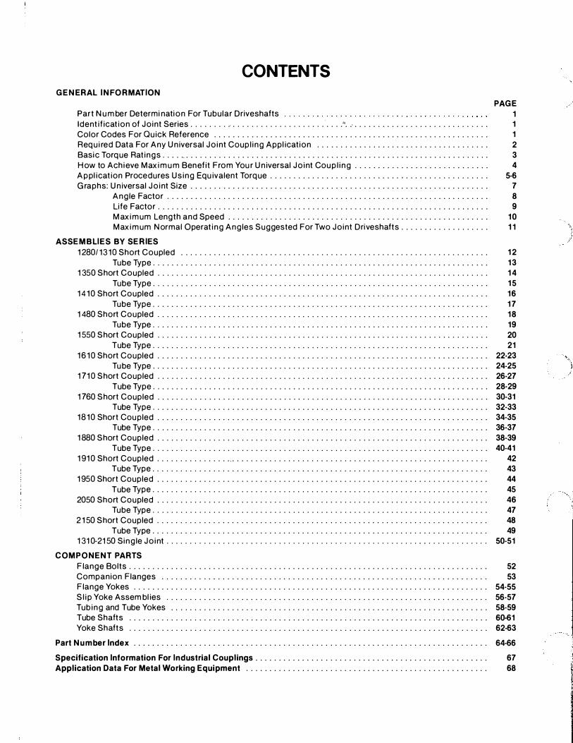
CONTENTS GENERAL INFORMATION
Part Number Determi nation For Tubular Drivesha fts PAGE
1 Ident i fi cat ion o f Jo int Series . . . . . . . . . . . . . . . . . . . . . . . . . . . . . . . . . ''. -'. . . . . . . . . . . . . . . . . . . . . . . . . . . . . 1 Color Codes For Qui ck Re feren ce . . . . . . . . . . . . . . . . . . . . . . . . . . . . . . . . . . . . . . . . . . . . . . . . . . . . . . . . . . . 1 Re qu i red Data For An y Un iversal Jo int Coup l ing Appl i cation . . . . . . . . . . . . . . . . . . . . . . . . . . . . . . . . . . . . . 2 Basi c Tor que Rat ings . . . . .. . . . . . . . . . . . . . . . . . . . . . . . . . . . . . . . . . . . . . . . . . . . . . . . . . . . . . . . . . . . . . . . . . 3 Ho w to A ch ieve Max imum Bene fit From You r Un iversal Jo int Coup l i ng . . . . . . . . . . . . . . . . . . . . . . . . . . . . . 4 Appl i cat ion Pro cedures Us ing Equ ivalent Tor que . . . . . . . . . . . . . . . . . . . . . . . . . . . . . . . . . . . . . . . . . . . . . . . 5·6 Graphs : Un iversal Jo int Size . . . . . . . . . . . . . . . . . . . . . . . . . . . . . . . . . . . . . . . . . . . . . . . . . . . . . . . . . . . . . . . . 7
Angle Fa ctor . . . . . . . . . . . . . . . . . . . . . . . . . . . . . . . . . . . . . . . . . . . . . . . . . . . . . . . . . . . . . . . . . . . . . 8 Li fe Fa ctor . . . . . . . . . . . . . . . . . . . . . . . . . . . . . . . . . . . . . . . . . . . . . . . . . . . . . . . . . . . . . . . . . . . . . . . 9 Max imum Length and Speed . . . . . . . . . . . . . . . . . . . . . . . . . . . . . . . . . . . . . . . . . . . . . . . . . . . . . . . . 10 Max imum Normal Operat ing Ang les Suggested For Two Joint Drivesha fts . . . . . . . . . . . . . . . . . . . 11
ASSEMBLIES BY SERIES 1 280/ 1 3 1 0 Short Coupled . . . . . . . . . . . . . . . . . . . . . . . . . . . . . . . . . . . . . . . . . . . . . . . . . . . . . . . . . . . . . . . . . . 12
Tube Type . . . . . . . . . . . . . . . . . . . . . . . . . . . . . . . . . . . . . . . . . . . . . . . . . . . . . . . . . . . . . . . . . . . . . . . . 13 1 350 Short Coupled . . . . . . . . . . . . . . . . . . . . . . . . . . . . . . . . . . . . . . . . . . . . . . . . . . . . . . . . . . . . . . . . . . . . . . . 14
Tube Type . . . . . . . . . . . . . . . . . . . . . . . . . . . . . . . . . . . . . . . . . . . . . . . . . . . . . . . . . . . . . . . . . . . . . . . . 15 1 4 1 0 Short Coupled . . . . . . . . . . . . . . . . . . . . . . . . . . . . . . . . . . . . . . . . . . . . . . . . . . . . . . . . . . . . . . . . . . . . . . . 16
Tube Type . . . . . . . . . . . . . . . . . . . . . . . . . . . . . . . . . . . . . . . . . . . . . . . . . . . . . . . . . . . . . . . . . . . . . . . . 17 1 480 Short Coupled . . . . . . . . . . . . . . . . . . . . . . . . . . . . . . . . . . . . . . . . . . . . . . . . . . . . . . . . . . . . . . . . . . . . . . . 18
Tube Type . . . . . . . . . . . . . . . . . . . . . . . . . . . . . . . . . . . . . . . . . . . . . . . . . . . . . . . . . . . . . . . . . . . . . . . . 19 1 550 Short Coupled . . . . . . . . . . . . . . . . . . . . . . . . . . . . . . . . . . . . . . . . . . . . . . . . . . . . . . . . . . . . . . . . . . . . . . . 20
Tube Type . . . . . . . . . . . . . . . . . . . . . . . . . . . . . . . . . . . . . . . . . . . . . . . . . . . . . . . . . . . . . . . . . . . . . . . . 21 1 6 1 0 Short Coupled . . . . . . . . . . . . . . . . . . . . . . . . . . . . . . . . . . . . . . . . . . . . . . . . . . . . . . . . . . . . . . . . . . . . . . . 22·23
Tube Type . . . . . . . . . . . . . . . . . . . . . . . . . . . . . . . . . . . . . . . . . . . . . . . . . . . . . . . . . . . . . . . . . . . . . . . . 24-25 1 71 0 Short Coupled . . . . . . . . . . . . . . . . . . . . . . . . . . . . . . . . . . . . . . . . . . . . . . . . . . . . . . . . . . . . . . . . . . . . . . . 26-27
Tube Type . . . . . . . . . . . . . . . . . . . . . . . . . . . . . . . . . . . . . . . . . . . . . . . . . . . . . . . . . . . . . . . . . . . . . . . . 28·29 1 760 Short Coupled . . . . . . . . . . . . . . . . . . . . . . . . . . . . . . . . . . . . . . . . . . . . . . . . . . . . . . . . . . . . . . . . . . . . . . . 30·31
Tube Type . . . . . . . . . . . . . . . . . . . . . . . . . . . . . . . . . . . . . . . . . . . . . . . . . . . . . . . . . . . . . . . . . . . . . . . . 32·33 1 8 1 0 Short Coupled . . . . . . . . . . . . . . . . . . . . . . . . . . . . . . . . . . . . . . . . . . . . . . . . . . . . . . . . . . . . . . . . . . . . . . . 34-35
Tube Type . . . . . . . . . . . . . . . . . . . . . . . . . . . . . . . . . . . . . . . . . . . . . . . . . . . . . . . . . . . . . . . . . . . . . . . . 36-37 1 880 Short Coupled . . . . . . . . . . . . . . . . . . . . . . . . . . . . . . . . . . . . . . . . . . . . . . . . . . . . . . . . . . . . . . . . . . . . . . . 38-39
Tube Type . . . . . . . . . . . . . . . . . . . . . . . . . . . . . . . . . . . . . . . . . . . . . . . . . . . . . . . . . . . . . . . . . . . . . . . . 40·41 1 91 0 Short Coupled . . . . . . . . . . . . . . . . . . . . . . . . . . . . . . . . . . . . . . . . . . . . . . . . . . . . . . . . . . . . . . . . . . . . . . . 42
Tube Type . . . . . . . . . . . . . . . . . . . . . . . . . . . . . . . . . . . . . . . . . . . . . . . . . . . . . . . . . . . . . . . . . . . . . . . . 43 1 950 Short Coupled . . . . . . . . . . . . . . . . . . . . . . . . . . . . . . . . . . . . . . . . . . . . . . . . . . . . . . . . . . . . . . . . . . . . . . . 44
Tube Type . . . . . . . . . . . . . . . . . . . . . . . . . . . . . . . . . . . . . . . . . . . . . . . . . . . . . . . . . . . . . . . . . . . . . . . . 45 2050 Short Coupled . . . . . . . . . . . . . . . . . . . . . . . . . . . . . . . . . . . . . . . . . . . . . . . . . . . . . . . . . . . . . . . . . . . . . . . 46
Tube Type . . . . . . . . . . . . . . . . . . . . . . . . . . . . . . . . . . . . . . . . . . . . . . . . . . . . . . . . . . . . . . . . . . . . . . . . 47 2 1 50 Short Coupled . . . . . . . . . . . . . . . . . . . . . . . . . . . . . . . . . . . . . . . . . . . . . . . . . . . . . . . . . . . . . . . . . . . . . . . 48
Tube Type . . . . . . . . . . . . . . . . . . . . . . . . . . . . . . . . . . . . . . . . . . . . . . . . . . . . . . . . . . . . . . . . . . . . . . . . 49 1 31 0-21 50 Sing le Jo int . . . . . . . . . . . . . . . . . . .. . . . . . . . . . . . . . . . . . . . . . . . . . . . . . . . . . . ... . . . . . . . . . . . . 50·51
COMPONENT PARTS Flange Bolts . . . . . . . . . . . . . . . . . . . . . . . . . . . . . . . . . . . . . . . . . . . . . . . . . . . . . . . . . . . . . . . . . . . . . . . . . . . . . 52 Companion Flanges . . . . . . . . . . . . . . . . . . . . . . . . . . . . . . . . . . . . . . . . . . . . . . . . . . . . . . . . . . . . . . . . . . . . . . 53 Flange Yo kes . . . . . . . . . . . . . . . . . . . . . . . . . . . . . . . . . . . . . . . . . . . . . . . . . . . . . . . . . . . . . . . . . . . . . . . . . . . . 54·55 Sl ip Yo ke Assem bl ies . . . . . . . . . . . . . . . . . . . . . . . . . . . . . . . . . . . . . . . . . . . . . . . . . . . . . . . . . . . . . . . . . . . . . 56·57 Tub ing and Tube Yo kes . . . . . . . . . . . . . . . . . . . . . . . . . . . . . . . . . . . . . . . . . . . . . . . . . . . . . . . . . . . . . . . . . . . . 58-59 Tube Sha fts . . . . . . . . . . . . . . . . . . . . . . . . . . . . . . . . . . . . . . . . . . . . . . . . . . . . . . . . . . . . . . . . . . . . . . . . . . . . . 60·61 Yo ke Sha fts . . . . . . . . . . . . . . . . . . . . . . . . . . . . . . . . . . . . . . . . . . . . . . . . . . . . . . . . . . . . . . . . . . . . . . . . . . . . . 62·63
Part Number Index . . . . . . . . . . . . . . . . . . . . . . . . . . . . . . . . . . . . . . . . . . . . . . . . . . . . . . . . . . . . . . . . . . . . . . . . . . . . 64·66
Specification Information For Industrial Couplings . . . . . . . . . . . . . . . . . . . . . . . . . . . . . . . . . . . . . . . . . . . . . . . . . . 67 Application Data For Metal Working Equipment . . . . . . . . . . . . . . . . . . . . . . . . . . . . . . . . . . . . . . . . . . . . . . . . . . . . 68
INTRO D UCTIO N
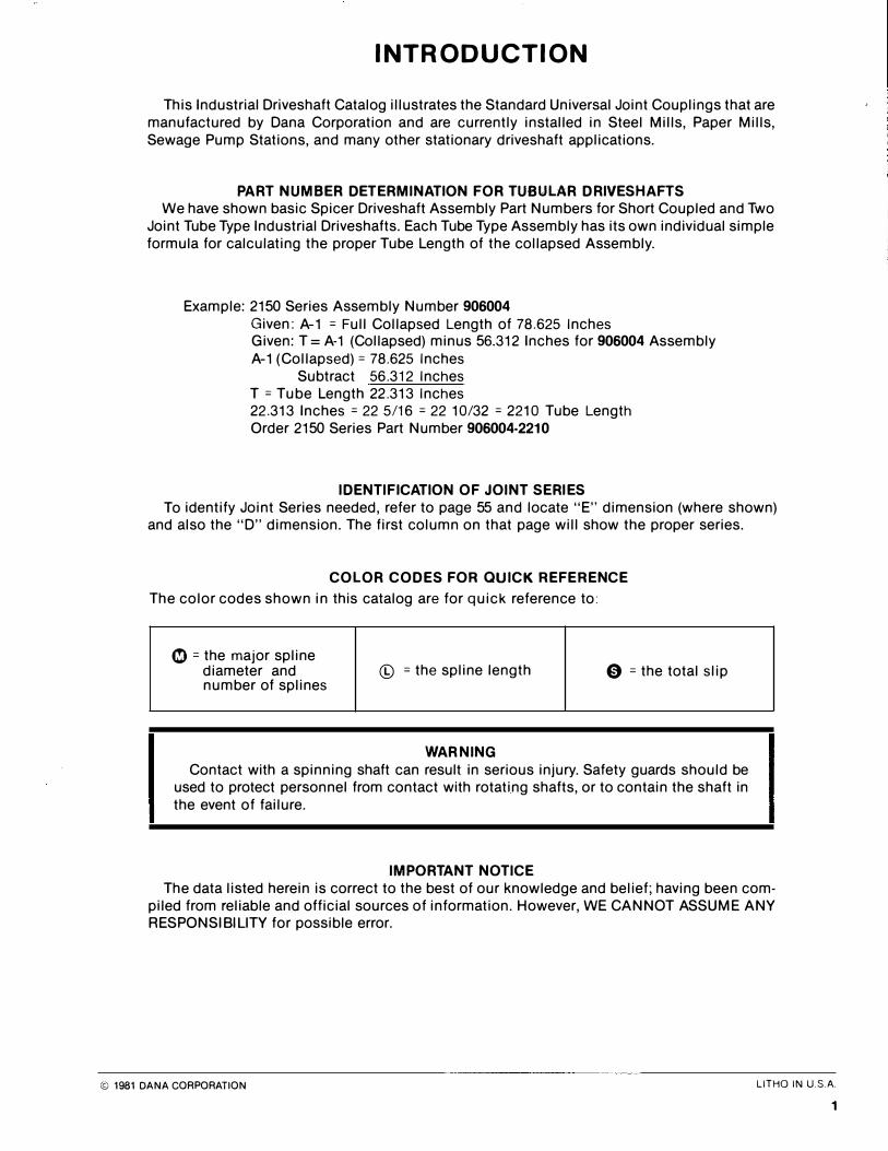
This Industrial Driveshaft Catalog illustrates the Standard Universal Joint Couplings that are manufactured by Dana Corporation and are currently installed in Steel Mills, Paper Mills, Sewage Pump Stations, and many other stationary driveshaft applications.
PART NUMBER DE TERMINATION FOR TUBULAR DRIVE SHA FTS We have shown basic Spicer Driveshaft Assembly Part Numbers for Short Coupled and Two
Joint Tube Type Industrial Driveshafts. Each Tube Type Assembly has its own individual simple formula for calculating the proper Tube Length of the collapsed Assembly.
Example: 2150 Series Assembly Number 906004
Given: A-1 = Full Collapsed Length of 78.625 Inches Given: T = A-1 (Collapsed) minus 56.312 Inches for 906004 Assembly A-1 (Collapsed)= 78.625 Inches
Subtract 56.312 Inches T =Tube Length 22.313 Inches 22.313 Inches = 22 5/16 = 22 10/32 = 2210 Tube Length Order 2150 Series Part Number 906004-2210
IDENTI FICATION O F JO INT SERIE S To identify Joint Series needed, refer to page 55 and locate "E" dimension (where shown)
and also the "D" dimension. The first column on that page will show the proper series.
COLOR CODE S FOR QUICK RE FERENCE
The color codes shown in this catalog are for quick reference to:
�=the major spline diameter and © = the spline length 0 =the total slip number of splines
WARNING Contact with a spinning shaft can result in serious injury. Safety guards should be
used to protect personnel from contact with rotating shafts, or to contain the shaft in the event of failure.
IMPORTANT NO TICE The data listed herein is correct to the best of our knowledge and belief; having been com
piled from reliable and official sources of information. However, WE CANNOT ASSUME ANY RESPONSIBILITY for possible error.
© 1981 DANA CORPORATION LITHO IN U.SA. 1
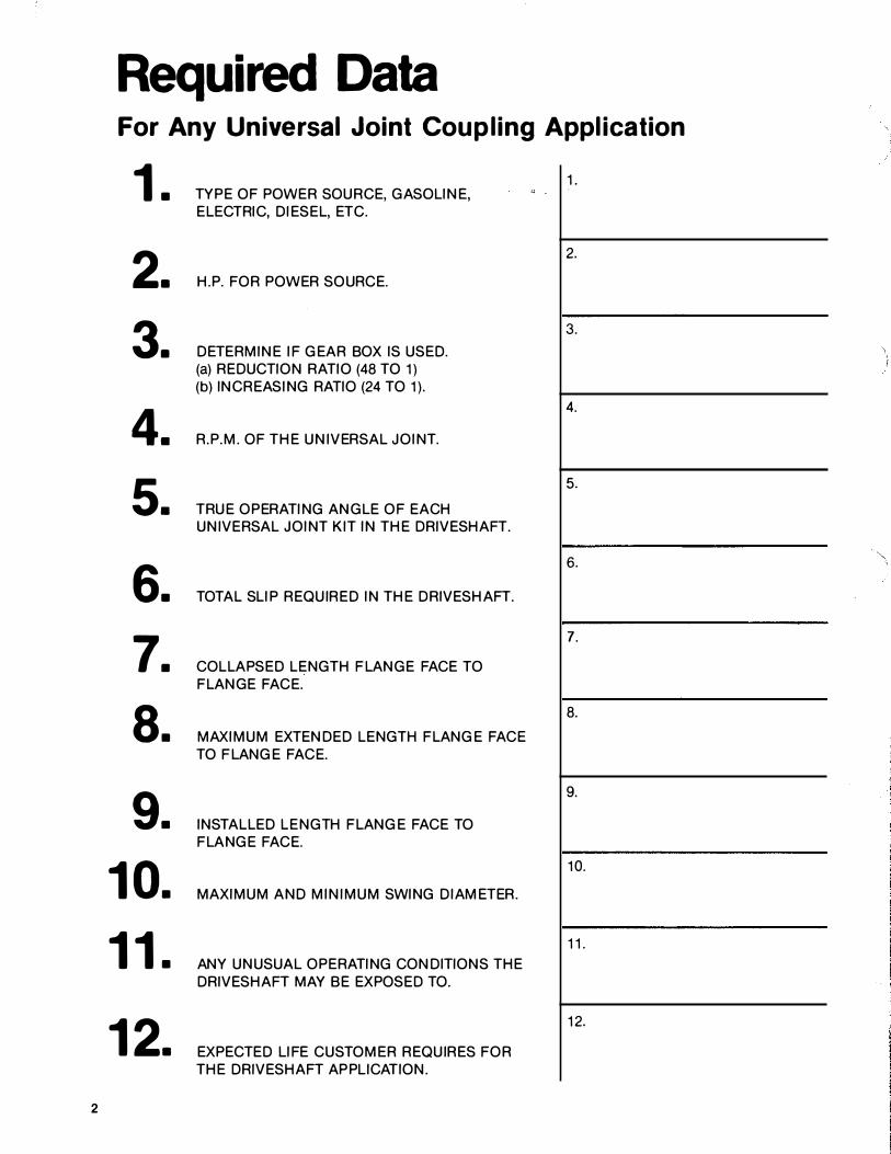
Required Data For Any Universal Joint Coupling Application
1. TYPE OF POWER SOURCE, GASOLINE, 1.
ELECTRIC, DIESEL, ETC.
2. H.P. FOR POWER SOURCE.
2.
3. DETERMINE IF GEA R BOX IS USED.
3.
(a) REDUCTION RATIO (48 TO 1) (b) INCREASING RATIO (24 TO 1).
4. R.P.M. OF T HE UNIVERSA L JOINT.
4.
5. T RUE OPERATING ANGLE OF EACH
5.
UNIVERSA L JOINT KIT IN T HE DRIVESHAFT.
6. TOTA L SLIP REQUIRED IN T HE DRIVESHAFT.
6.
7. COL LAPSED LENGTH F LANGE FACE TO
7.
F LANGE FACE.
8. MAXIMUM EXTENDED LENGTH F LANGE FACE
8.
TO F LANGE FACE.
9. INSTA L LED LENGTH F LANGE FACE TO
9.
F LANGE FACE.
10. MAXIMUM AND MINIMUM SWING DIAMETER.
10.
11. ANY UNUSUA L OPERATING CONDITIONS T HE
11.
DRIVESHAFT MAY BE EXPOSED TO.
12. EXPECTED LIFE CUSTOMER REQUIRES FOR
12.
T HE DRIVESHAFT APPLICATION.
2
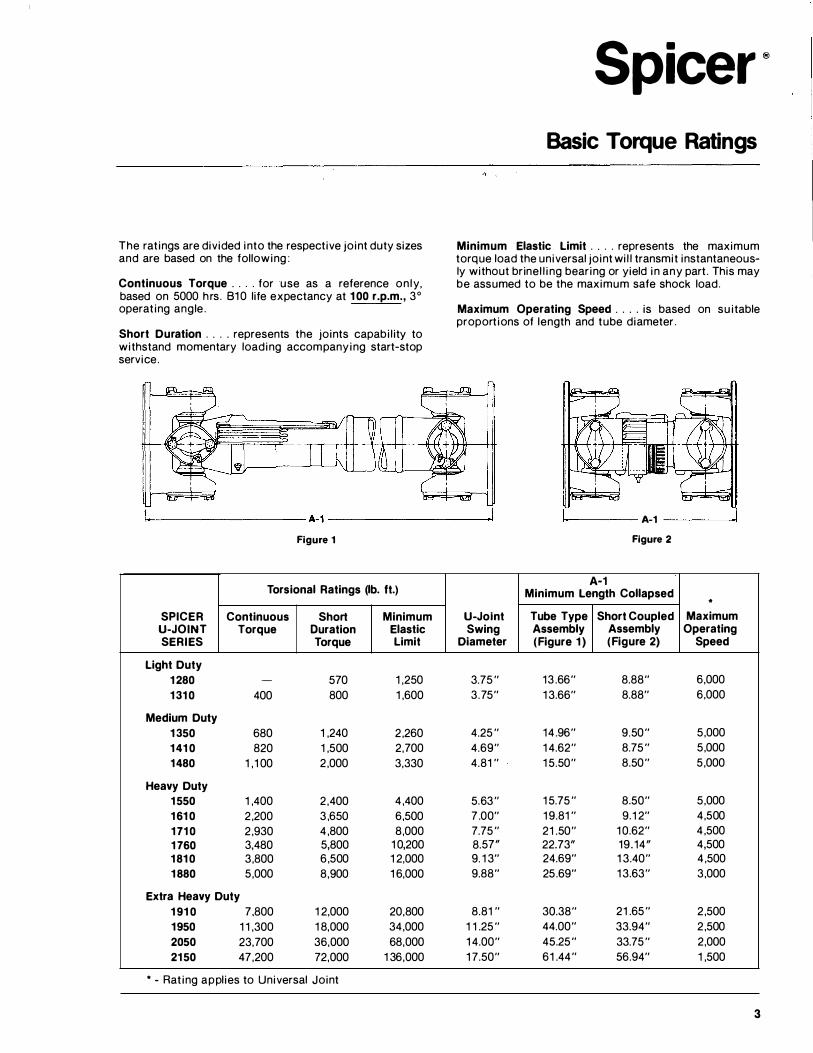
The ratings are divided into the respective joint duty sizes and are based on the following:
Continuous Torque . ... for use as a reference on ly, based on 5000 hrs. 810 life expectancy at 100 r.p.m., 3 ° operating angle.
Short Duration .. . . represents the joints capability to withstand momentary loading accompanying start-stop service.
Figure 1
Torsional Ratings (lb. ft.)
SPICER Continuous Short Minimum U-JOINT Torque Duration Elastic SERIES Torque Limit
Light Duty 1280 - 570 1 ,250 1310 400 800 1 ,600
Medium Duty 1350 680 1 ,240 2 ,260 1410 820 1 ,500 2 ,700 1480 1 ,1 00 2 ,000 3 ,330
Heavy Duty 1550 1 ,400 2 ,400 4 ,400 1610 2 ,200 3 ,650 6 ,500 1710 2 ,930 4 ,800 8 ,000 1760 3 ,480 5,800 1 0 ,200 1810 3 ,800 6 ,500 1 2 ,000 1880 5,000 8 ,900 1 6 ,000
Extra Heavy Duty 1910 7 ,800 1 2 ,000 20 ,800 1950 1 1 ,300 1 8 ,000 34 ,000 2050 23 ,700 36 ,000 68 ,000 2150 47 ,200 72 ,000 1 36 ,000
* - Rating applies to Universal Joint
Spicer· Basic Torque Ratings
Minimum Elastic Limit .... represents the maximum torque load the universal joint wil l transmit instantaneously without brinel ling bearing or yield in any part. This may be assumed to be the maximum safe shock load.
Maximum Operating Speed . . . . is based on suitable proportions of length and tube diameter.
U-Jolnt Swing
Diameter
3.75" 3.75"
4.25" 4.69 " 4.81 "
5.63 " 7 .00 " 7.75" 8.57" 9. 1 3 " 9.88 "
8.81 " 1 1 .25" 1 4.00 " 1 7.50 "
1------- A-1 -----l Figure 2
A-1 Minimum Length Collapsed * Tube Type Short Coupled Maximum Assembly Assembly Operating (Figure 1) ( Figure 2) Speed
13 .66 " 8.88 " 6 ,000 1 3.66 " 8.88 " 6 ,000
14 .96 " 9.50 " 5,000 1 4.62 " 8.75" 5,000 1 5.50 " 8.50 " 5,000
1 5.75" 8 .50 " 5,000 1 9.81 " 9 .1 2 " 4 ,500 21 .50 " 1 0.62 " 4 ,500 22.73" 19.14" 4 ,500 24.69 " 1 3.40 " 4 ,500 25.69 " 1 3.63 " 3 ,000
30.38 " 21 .65" 2 ,500 44.00 " 33.94 " 2 ,500 45.25" 33.75" 2 ,000 61 .44 " 56.94 " 1 ,500
3
How to Achieve Maximum Benefit From Your Universal Joint Coupling.
Universal Joint Couplings offer a great deal of flexibility in the alignment of driving and driven units. They transmit torque through an angle and provide long life. These are the primary reasons for using Universal Joint Couplings. The ability to change length and angle during rotation under torque load further increases the usefulness of Universal Joint Couplings.
Application Guidelines. Size selection depends on the following basic parameters: 1. Continuous Operating Torque. 2. Continuous True Running Angles. 3. Desired Service Life. 4. Power Source To determine the Universal Joint Coupling size required in Figure 1 , use the following formula:
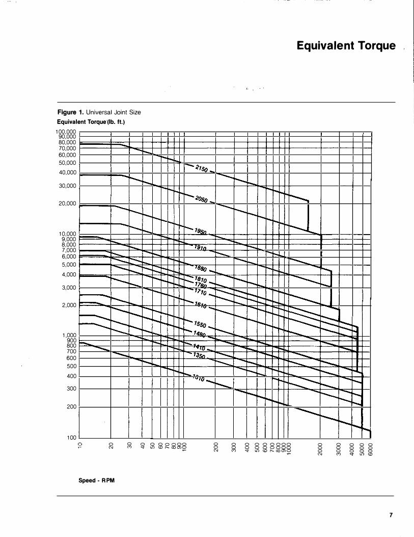
Equivalent Torque= T X FAx FL X Fp T =Continuous Operating Torque
in lb. ft.= HP X 5252 RPM
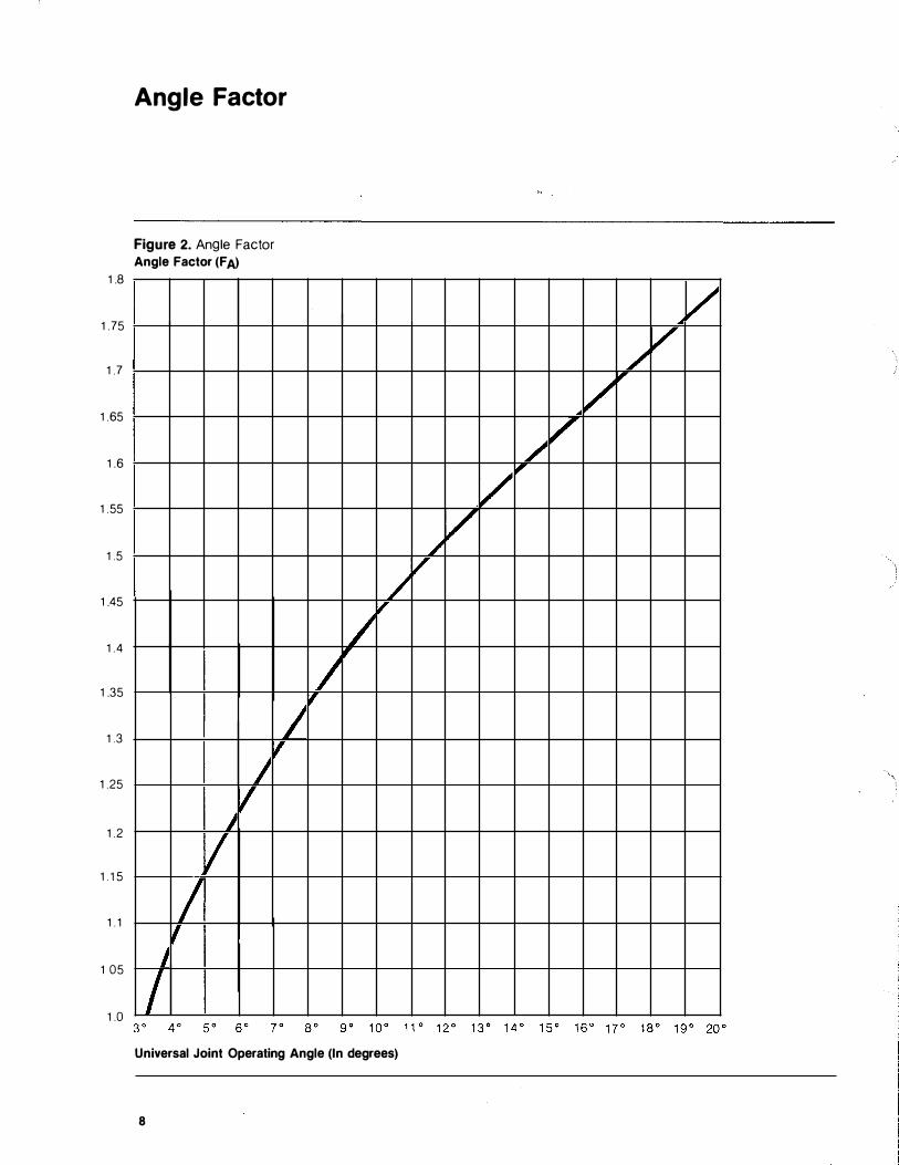
FA= Angle Factor from Figure 2. FL = Life Factor from Figure 3. Fp =Power Factor
Power S ource
Electric Motor
Gasoline Engine
D1esel Engine
Fp 100 1.25 1.50
In addition to the above, the maximum start up torque should be checked against the "Short Duration Torque" rating for the universal joint size applicable. The start up torque should not exceed this rating in order to obtain maximum fatigue life of the driveshaft assembly. Momentary shock loads, if any, should not exceed the torsional strength rating. This will assure that the universal joint size selected will have adequate bearing capacity to resist brinelling when subjected to shock loading.
If a service factor is requested by the user, the following statement will determine if the driveline is large enough. "Short Duration Torque" must be equal to, or greater than, Continuous Operating Torque times the Service Factor (SOT E; COT x SF).
4
Driveshaft Length and Rotational Speed. In applications where long lengths of shafts are required for transmission of power from the driving unit to the driven unit, the speed is restricted by the transverse whirling speed. This is commonly referred to as the shaft "Critical Speed:' This speed is a function of the tube diameter, wall thickness and the effective length.
Figure 4 illustrates the safe operating speeds for standard driveshaft tube sizes in the Spicer product line. This safe operating speed is based on .75 of the true calculated critical speed for the effective length shown.
In some _applications, vibrations from the half critical can be troublesome. For these applications the operating speed should be above or below two-thirds the maximum indicated on Figure 4.
Where lengths are such that avoidance of the critical speed by use of a larger tube diameter is not practical, a multiple driveshaft arrangement having intermediate shaft support bearings is recommended. This type of arrangement is especially recommended for high speed applications whereby effective lengths exceed 70 inches and driveshaft balance is critical to the drive or driven member.
Universal Joint Angles and Rotational Speed. The Cardan type universal joint, when operating at an angle results in nonuniform motion output given uniform motion input. Because of this characteristic, care must be taken in inboard yoke alignment and driveshaft installation angles.
When the universal joint installation angles lie in the same plane, inboard yoke cross holes are in line. This is the standard method for driveshaft assembly. Given equal universal joint angles on each end of the driveshaft results in maximum cancellation. The non-uniform motion from the first universal joint in the system is cancelled at the output of the second universal joint.
When out of plane universal joint angles exist in an installation, standard inboard yoke alignment does not apply. For this condition it is suggested that Spicer universal joint engineering be contacted for determination of proper yoke alignment.
The maximum single universal joint angle in a two joint system is limited by the speed of rotation. Figure 5 shows the maximum normal operating angles suggested for a two joint system. The angles shown limits the angular acceleration to 1 000 rad/sec� This angular acceleration, although cancelled with exactly equal universal joint angles at the output of the second joint, is still prevalent on the center section of the driveshaft assembly. Because of this excitation factor, limits must be imposed.
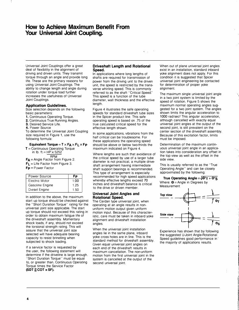
Determination of the maximum continuous universal joint angle in an application takes into consideration any offset in the top view as well as the offset in the side view.
This is usually referred to as the "True Operating Angle" and can be closely approximated by the following:
True Operating Angle =�r.e:-::.-T-+'9:-::·
-s
Where: 9 =Angle in Degrees by Measurement
Top view � _ _ _j__ -- � - far
Experience has shown that by following the suggested U-Joint Angle-Rotational Speed guidelines good performance in· the majority of applications results.
Application Procedures Using Equivalent Torque
T he formula ET = T x FAx FL x FP provides an easy method of determining your driveshaft requirements. Equivalent Torque (ET) takes into consideration the Torque (T) which is applied to the shaft, ·the angles
(FA), and their effect on Service Life, the amount of excess capacity (FL), required to insure required B-1 0 Life, and a factor (FP), to allow for Torsional Excitation by the power source.
First solve the equation, then use the Equivalent Torque Chart (Fig. 1) page 7, to select the right Series. Secondly make sure the Maximum Start-Up Torque does not exceed the "Short Duration Torque;· as shown on the chart on page 3. Using these guidelines, along with our Maximum Safe Operating Speed Chart (Fig. 4) page 10, will assure a satisfactory installation.
One further note of caution on Operating Speeds. At times the Half (V2) Critical Speed can be a problem as it could set up vibrations in your drive system. Try to avoid having an installation which runs at 66.7% of the Maximum Safe Operating Speed.
Here are a few examples which illustrate the Equivalent Torque Formula. All values are taken from charts on the next few pages.
ET =Equivalent Torque T =HPX5252
RPM FA =Angle Factor (Fig. 2 page 8) FL =Life Factor (Fig. 3 page 9)
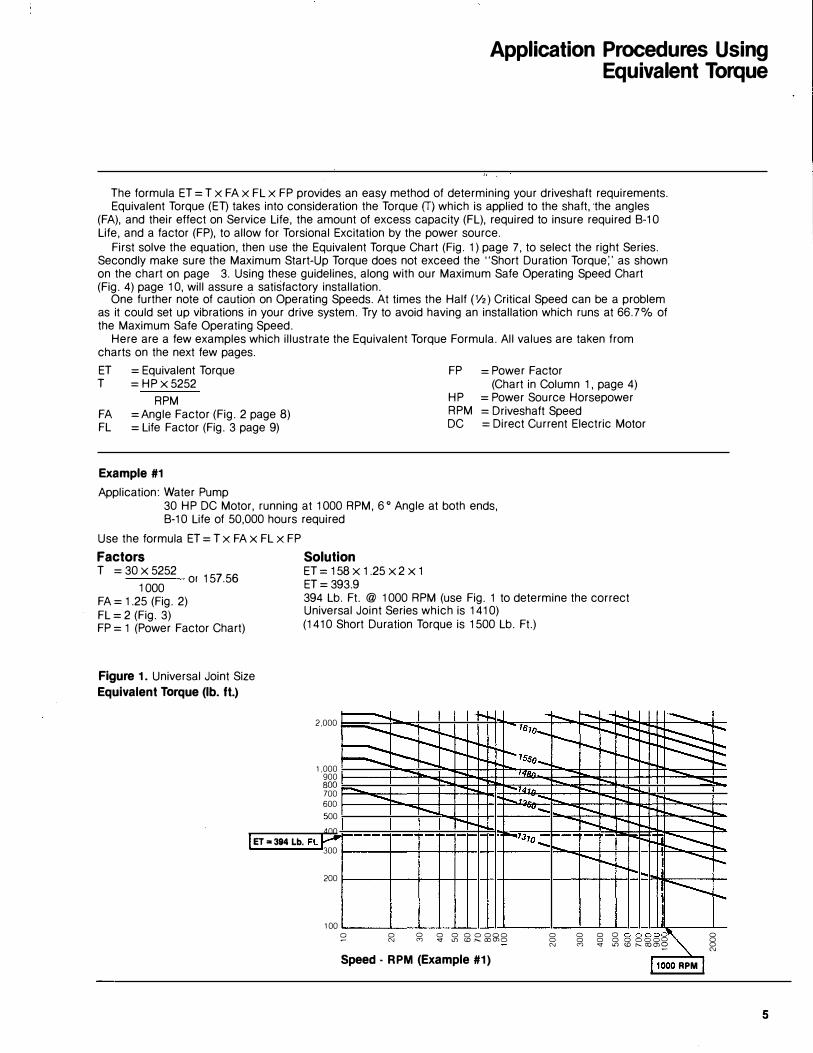
Example #1
Application: Water Pump
FP
HP RPM DC
= Power Factor (Chart in Column 1, page 4)
=Power Source Horsepower = Driveshaft Speed =Direct Current Electric Motor
30 HP DC Motor, running at 1000 RPM, 6° Angle at both ends, B-1 0 Life of 50,000 hours required
Use the formula ET = T x FA X FL x FP
Factors Solution T = 30 X 5252
157 56 ET = 1 58 X 1 .25 X 2 X 1
1 000 or ·
ET = 393.9
FA= 1.25 (Fig. 2) 394 Lb. Ft. @ 1000 RPM (use Fig. 1 to determine the correct
FL = 2 (Fig. 3) Universal Joint Series which is 141 0)
FP = 1 (Power Factor Chart) (141 0 Short Duration Torque is 1500 Lb. Ft.)
Figure 1. Universal Joint Size
Equivalent Torque (lb. ft.)
2.000 - r- � ........ -- .� !'--- 1 ...............
---........ ........ 1Bto- --........ r-.... 1-- � 1"-- r-........ r--... 1---- ........ ........ r--r-""I'- r--........ -- r-. �r- 1-tsso_ r--........ ........ r--1.000
900 - I' 1"1Bn.
BOO .... .... - ...... 700 - .... -..141n .... .... 600
- r.....,1?, .......... ..... 1'--. r--... ........ . .,_ ........ 1-- ..........
1-� !'-...
500 r--r--r- r-- r-r-- -......... .... 400 I ET .. 394 Lb. Ft.P --- ·- - .-- !"'" 1""13to _ -· ·- r-1"" .... 1'- � 300 .... 1'--.
........ ........ I ......_ 1-r-r-..
200 ............... 1-100
S' 0 0 0 0 o o ooo 0 0 0 0 0 0001� 0 N M ..;t l.() w r-... romo 0 0 0 0 0 oooo 0 N M " l[) <D r- roms 0 N Speed · RPM (Example #1) 11000 RPM I
5
Practical Application Procedures
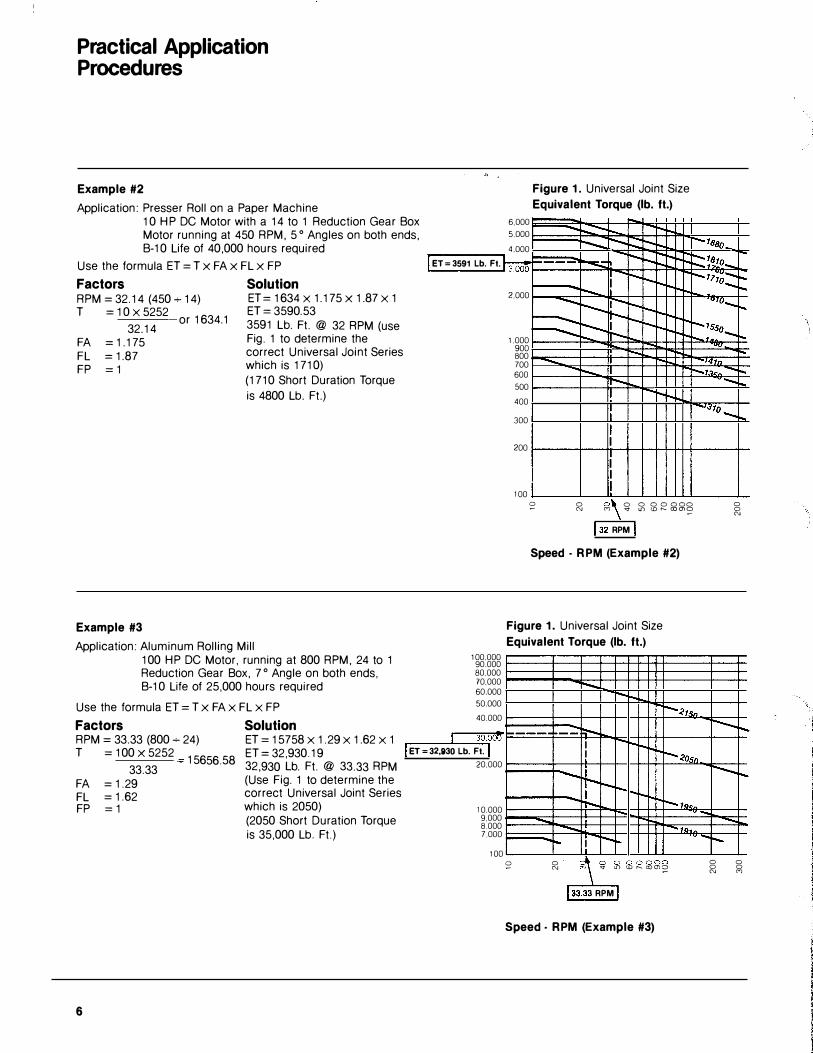
Example #2 Application: Presser Roll on a Paper Machine
1 0 H P DC Motor with a 14 to 1 Reduction Gear Box Motor running at 450 RPM, 5o Angles on both ends, B-1 0 Life of 40,000 hours required
Use the formula ET = T x FAx FL x FP
Factors Solution RPM= 32.14 (450-;.. 14) ET= 1634 X 1.175x 1.87 X 1 T = 1 0 X 5252 ET = 3590.53
32_14 or 1634·1 3591 Lb. Ft. @ 32 RPM (use
FA = 1.175 Fig. 1 to determine the
FL = 1.87 correct Universal Joint Series
FP = 1 which is 171 0)
Example #3
(171 0 Short Duration Torque
is 4800 Lb. Ft.)
Application: Aluminum Rolling Mill 100 HP DC Motor, running at 800 RPM, 24 to 1 Reduction Gear Box, 7 o Angle on both ends, B-1 0 Life of 25,000 hours required
Use the formula ET = T x FA X FL X FP
Factors Solution RPM= 33.33 (800 � 24) ET = 15758 X 1.29 X 1.62 X 1
6.000
5.000
4.000
Figure 1. Universal Joint Size
Equivalent Torque (lb. ft.)
... __ ......... -- ... ............ ...... .......: � -7BBo
I ET = 3591 Lb. Ft. h:oo! -· """"'=::.;: ... _ -..... .. ::::��!�--11�::::
I
100.000 90.000 80.000 70.000 60.000
50.000
40.000
2.000
1.000 900 800 700 600
500
400
300
200
100
I --... ...
...... ... ...... --!" --
"UfQ-... � t-- ... :---h. - .... r---tsso-
1-. � ,.... ......... -t47n
I-... 1"-..7 .• ,.. 1-. rr- · -
I---•.sto....._..,
I I
I I I
s: 0 �\ 0 0 0 0000 0 N M "
132 RPM I
L{) I..D r-- como �
Speed · RPM (Example #2)
0 N
Figure 1. Universal Joint Size
Equivalent Torque (lb. ft.)
!'-...... -�-..
r---27.<;, 30.001J 1-· =-- r-.. t--
T =100x 5252 ET=32,930.19
33.33 15656·58 32,930 Lb. Ft. @ 33.33 RPM
I ET = 32,1130 Lb. Ft. I I '!-. I r-..2osn.
FA = 1.29 (Use Fig. 1 to determine the
FL = 1 .62 correct Universal Joint Series
FP = 1 which is 2050)
6
(2050 Short Duration Torque is 35,000 Lb. Ft.)
20.000
10.000 9.000 8.000 7.000
100
......... +- --� � -+- ... r-..tg.,,
-- -ra. .... I r--.. -
s: 0 10 000000 0 0 N -q tD r...o r-- coms;: 0 0 N M
133.33 RPM
Speed · RPM (Example #3)
Equivalent Torque ,
Figure 1. Universal Joint Size
Equivalent Torque'(lb. ft.)
100,000 90,000 80,000 70,000 60,000
50,000
40,000
30,000
20,000
10,000 9,000 8,000 7,000 6,000
5,000
4,000
3,000
2,000
1,000 900 800 700 600
500
400
300
200
100
-I-.. .... r- -....<tsa .... r-.... --.... r---.... I-.. ""'"' .... I'--... � """ r-""" �<os0 .... �r--......
-.... r-... --.... r-... r-.... r-.. r-.... �"""-""" r-r- I"" """ �� .. r--...... ...... ........ I-.. t"'- 79sn .... """"' """' -""' I'--... . 19111 r-..
r-...... -""'"' r--.- I"' ,... r----.: t--""" l""o """� ["""-.. ""'"' r--........ -...... r--::: r-. � I'--�"--""
"11J8o .... """ ,...,... .._ ....... ,....
1"--. -r-.. """ T"-� r:::: 1Bto -r-.... --............. r-..... r-""" 7"lfin ..... I'--... t--""" ""'"' -r-.. """ -y-,70 F=::: F::::: !"" """""
-r--..-.. r-""""" ..... f::: � � ..... t""---tR ""'"' """ 1"'-r----.. r--... r-.. . ., ..... -�"""- I-r- .... """ """ """- � r---.... r- 1"'-
---.... """- t--1'--- """"" I'-tsso r-.... t-- r-t- � f:::::� r---.... 1'--r- �"""-r-.. -.... """"" r-1"--. ..... r---........ T"-� r-......... r-. ..... r-..74Rrt r--..... ""- .. """
-... - l""o.. --.... r-
-......
0 N
Speed - R PM
.._ r-.... .... I'--........ t.....
0 0 0 0 0 000 C') -..t l!) co t- co 0)0 �
.._ - ---- L"""' � --...... .. ,0 .... .._ ....... ,... �"""-..... 135n -...... """ .... ............... .............. -r-... �"""........ ............. -r-... -.... I"" -.... r-....... -�-- .. to.... ...... ... ,o ....... .... ""' �--.........
........ r-.... ............. r--.........
0 0 N
-.... t--�"""-.... .... I""
0 0 0 0 0 000 0 0 o o oooo C') -..t l!) co t- co 0) 0 �
-r--.... -.. ........ r-...
� -.............. r--.... r-....
0 0 0 N
r..... �
0 0 0 0 0 0 0 0 0 0 0 0 C') -..t l!) co
7
1.8
1.75
1.7
1.65
1.6
1.55
1.5
1.45
1.4
1.35
1.3
1.25
1.2
115
1 .1
1 05
1.0
Angle Factor
Figure 2. Angle Factor
Angle Factor (FA)
/ If
I I
J
I
J v
J I I I
/ /
,
/� if'
Universal Joint Operating Angle (In degrees)
8
/ / v
/ ,.
/ / v ,
/ v v
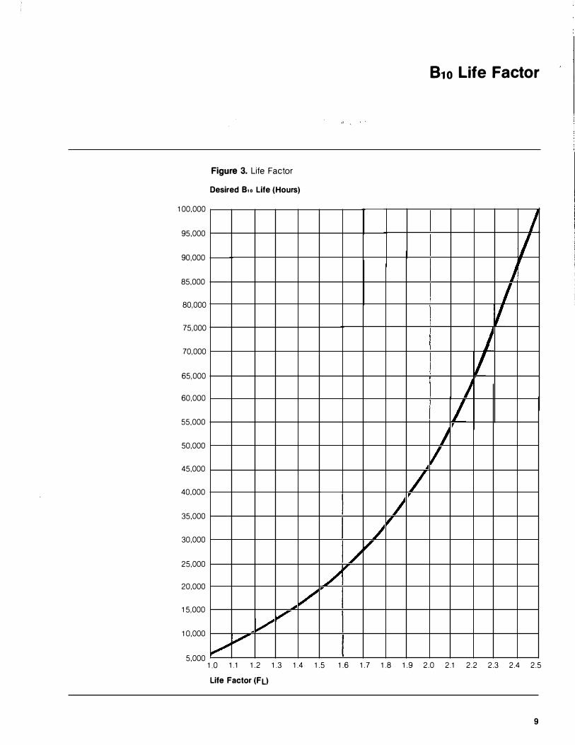
B1o Life Factor
Figure 3. Life Factor
Desired B.o Life (Hours)
100,000
95,000
90,000
L 1/ ,
85,000
80,000
75,000
70,000
65,000
60,000
55,000
J I v J
If I
I 50,000 I I 45,000
40,000 / 35,000
30,000
25,000
20,000
15,000
10,000
J / ,
/ v
/ iJt"'
� v / V"
v , 5,000
1.0 1.1 1.2 1.3 1 .4 1 .5 1.6 1. 7 1.8 1.9 2.0 2.1 2.2 2.3 2.4 2.5
Life Factor (FL)
9
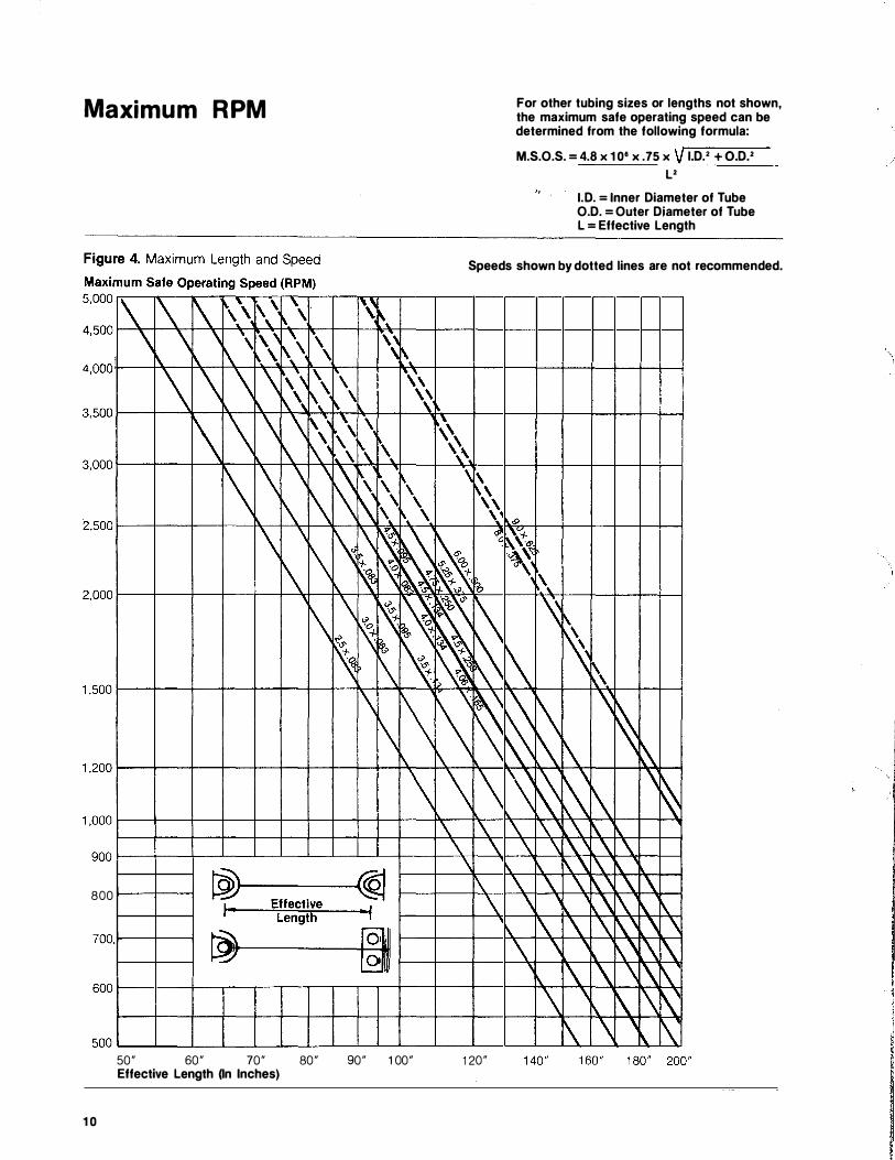
Maximum RPM
800 1----+--1
700.1----+--1
50" 60" 70" 80" 90" 1 00" Effective Length (In Inches)
10
For other tubing sizes or lengths not shown, the maximum safe operating speed can be determined from the following formula:
M.S.O.S. =4.8 X 108 X .75 X v I.D.' +0.D.2 L2
I. D.= Inner Diameter of Tube O.D. =Outer Diameter of Tube L = Effective Length
Speeds shown by dotted lines are not recommended.
120"
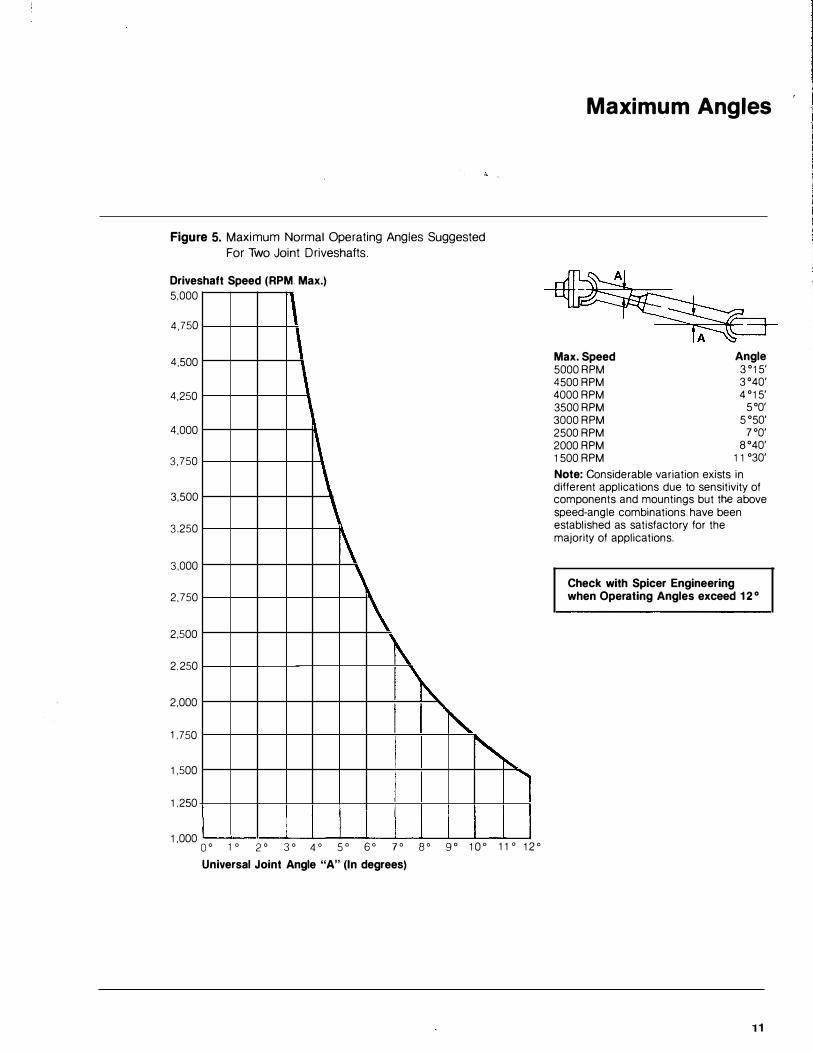
Figure 5. Maximum Normal Operating Angles Suggested
For Two Joint Driveshafts.
Driveshaft Speed (RPM. Max.) 5,000 11 4,750
\ ,
4,500
4,250
1\ \ '
4,000
3,750
3,500
\ \ 3,250
3,000
\ 2,750
2,500 i\. ' 2,250
i'\. '�
�� .....
2,000
1,750
1,500
1,250
1,000 Oo 1o 2o 3o 4o 5o 6o yo go go 10o 110 120
Universal Joint Angle "A" (In degrees)
Maximum Angles
Max. Speed 5000RPM 4500 RPM 4000 RPM 3500RPM 3000RPM 2500 RPM 2000 RPM 1500 RPM
Angle 3 °15' 3°40' 4 °15'
5°0' 5050'
7°0' 8°40'
11 °30'
Note: Considerable variation exists in different applications due to sensitivity of components and mountings but the above speed-angle combinations have been established as satisfactory for the majority of applications.
Check with Spicer Engineering when Operating Angles exceed 12°
11
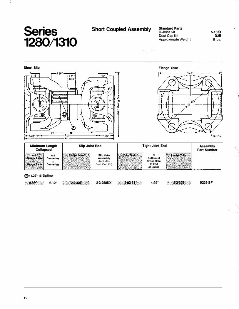
Series 1280/1310
Short Slip
Minimum Length Collapsed
0=1.25"·16 Spl ine
8.00" 6. 1 2"
12
Short Coupled Assembly Standard Parts U-Joint Kit
Slip Joint End
Slip Yoke Assembly (Includes
Dust Cap Kit)
2·3·258KX
Dust Cap Kit Approximate Weight
Flange Yoke
T ight Joint End
N Bottom of
Cross Hole to End
of Spline
4.59"
5·153X 028
Sibs.
Assembly Part Number
9235-SF
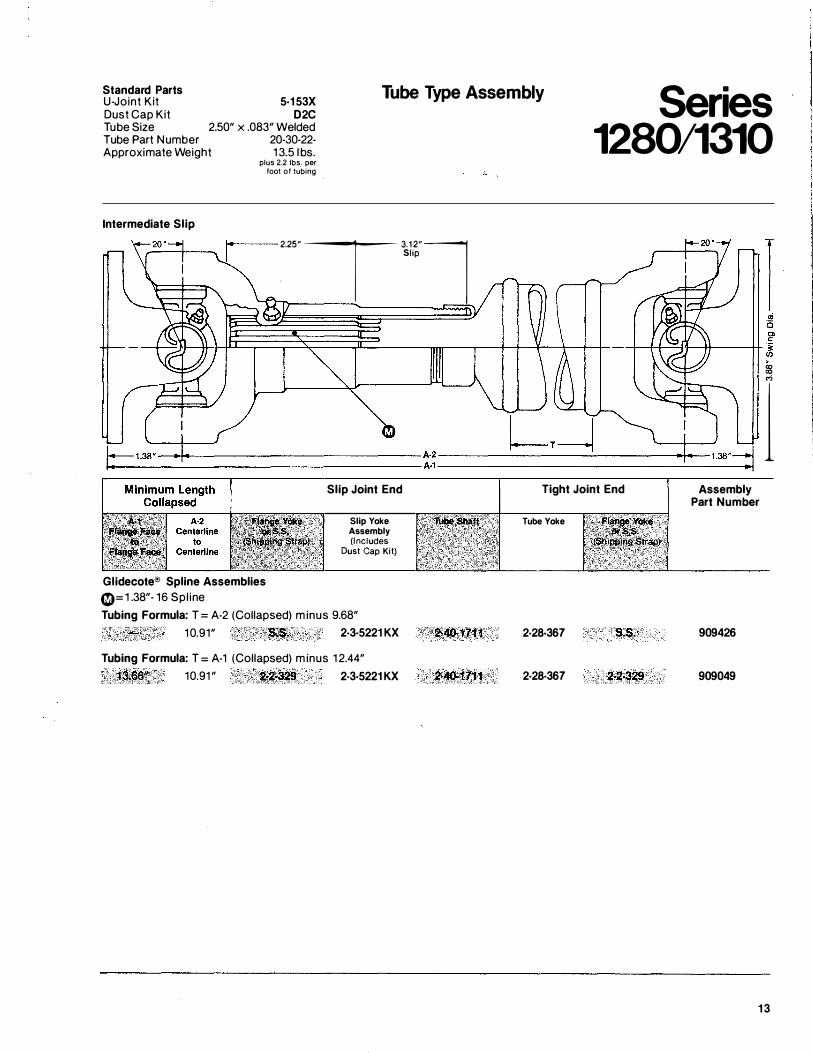
Standard Parts U-Joint Kit Dust Cap Kit Tube Size
5-153X D2C
2.50" x .083" Welded
Tube Type Assembly Series 1280/1310 Tube Part Number
Approximate Weight
Intermediate Slip
20-30-22-1 3.5 1bs.
plus 2.2 lbs. per foot of tubing
Slip 2.25
"T 3.1
2"l
' � ..;
---+j-4-----���----��,�-� l
Glidecote® Spline Assemblies �=1 .38"- 16 Spl ine
Slip Joint End
Slip Yoke Assembly (Includes
Dust Cap Kit)
Tubing Formula: T = A-2 (Collapsed) m inus 9.68" 1 0.91" '$;$. 2-3-5221KX
Tubing Formula: T = A-1 (Collapsed) m inus 1 2.44"
1:li�" 10.91 " 2.2·329 2-3-5221 KX
Tight Joint End
Tube Yoke
2-28-367 S:S;
2-28-367
Assembly Part Number
909426
909049
13
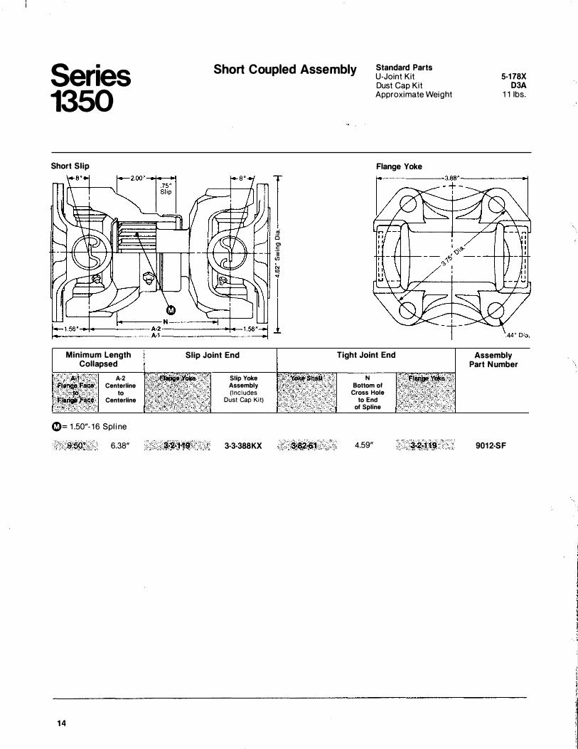
Series 1350 Short Slip
Minimum Length Collapsed
A::t Fl.lli!PFace to Frang. Fllee
A·2 Centerline
to Centerline
0= 1 .50"- 1 6 Spl i ne
9.50� 6.38"
14
Short Coupled Assembly Standard Parts U-Joint Kit
Slip Joint End
Slip Yoke Assembly (Includes
Dust Cap Kit)
3·3·388KX
I '" i5 CD c -� (J)
�82·61
Dust Cap Kit Approximate Weight
Flange Yoke
Tight Joint End
N Bottom of
Cross Hole to End
of Spline
4.59"
5-178X D3A
1 1 1bs.
Assembly Part Number
9012·SF
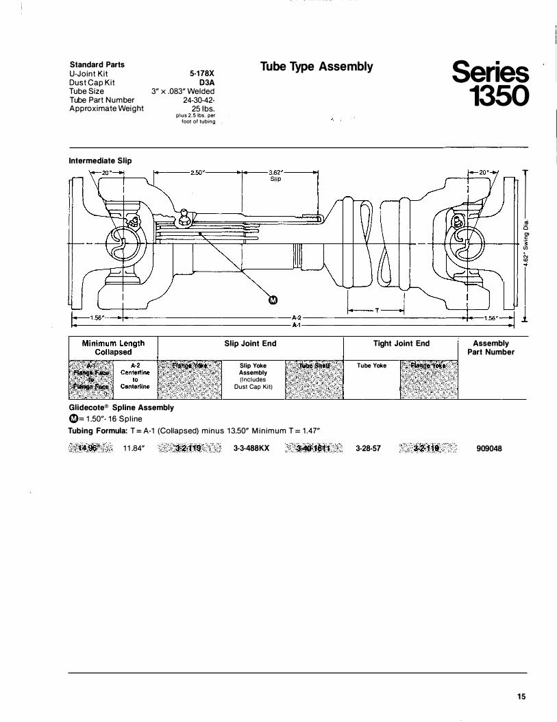
Standard Parts U-Joint Kit Dust Cap Kit Tube Size
5-178X D3A
3" x .083" Wel de d 24-30-42-
25 1bs.
Tube Type Assembly Series 1350 Tube Part Number
Approximate Weight
Intermediate Slip
plus 2.5 lbs. per foot of tubing
2.50"-r- 3.62"
I .,,,
I .; i5 C> c:
-t--t-t---"=:;t--tt----i!+ � �
�----::�----��,�-�I
Glidecote® Spline Assembly 0== 1 .50"- 1 6 Spl ine
Slip Joint End
Slip Yoke Assembly (Includes
Dust Cap Kit)
Tubing Formula: T==A-1 (Collapse d) minus 1 3.50" M in imum T = 1 .47"
1 1 .84" 3-3-488KX
Tight Joint End
Tube Yoke
3-28-57
Assembly Part Number
909048
15
Series 1410
Short Slip
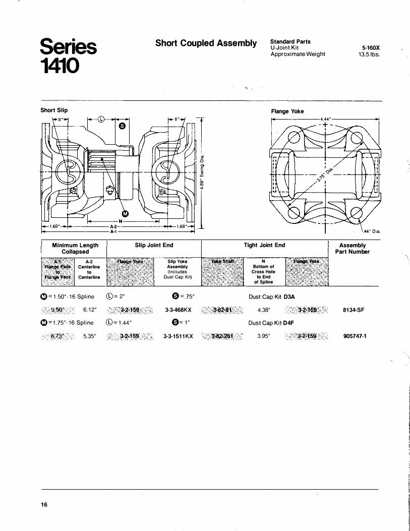
Short Coupled Assembly
.,; 0 0> c: -� Cll
m ...
Standard Parts U-Joint K i t Approximate Weight
Flange Yoke
----....:-1+----�:� N-_.2:;:rl---',�·� 1 Minimum Length
Collapsed
A_:� Fla� Face to Flange Face
A-2 Centerline
to Centerline
0= 1.50"-16 Spl i n e
9.50" 6.12" 0=1.75"-16 Spl i n e
8.73" 5.35"
16
Slip Joint End
©= 2" 3-2-159
©=1.44" 3-2·159
Slip Yoke Assembly (Includes
Dust Cap Kit)
0=.75" 3-3-468K X
0=1" 3-3-1511K X
3·82-81
Tight Joint End
N Bottom of
Cross Hole to End
of Spline
Dust Cap Kit D3A
4.38" Dust Cap Kit D4F
3.95"
3·2·159
5-160X 13.5 1bs.
Assembly Part Number
8134-SF
905747·1
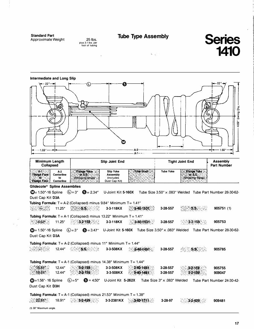
Standard Part Approximate Weight
Intermediate and Long Slip
25 1bs. plus 3.1 lbs. per
foot of tubing
Tube Type Assembly Series 1410
"' c: -1--+�=-i'I--H----++ -�
en
m ...
-----1------���----��,oo·� l Minimum Length
Collapsed Slip Joint End Tight Joint End Assembly
Part Number
A·1 A-2 FfllJl98: Face Centerline ��-- to
Fll,!ltQe Face Centerline
Glidecote® Spline Assemblies
Slip Yoke Assembly (Includes
Dust Cap Kit)
Tube Yoke
(!)::1 .50" -16 Spl ine ©=3 " 0= 2.34" Dust Cap Kit D3A
U -Joint Kit 5·160X Tube Si ze 3.50 " x .083 " Wel de d Tube Part Number 28-30 -62 -
Tubing Formula: T=A-2 ( Col la pse d) minus 9.84 " Min imum T= 1 .41 " 1 1 .25" _ , S.S, 3·3·118KX ,3-40·1531 3·28·557 s.s. 905751 (1 )
Tubing Formula: T = A-1 ( Col la pse d) minus 13.22 " Min imum T= 1 .41 " 14.6Z' 1 1 .25 " 3·2·159 3-3·118KX 3-40·1531 3-28·557 3·2·159 905753
0= 1 .50 "-16 S pl ine ©= 3 " 0 = 3.4 7" U-Joint Kit 5·160X Tube Si ze 3.50" x .083" Wel de d Tube Part Number 28 -30-62 -
Dust Ca p Kit D3A
Tubing Formula: T= A-2 ( Col lapse d) minus 1 1 " Min imum T= 1 .44" 12.44" S.S. 3·3·508KX 3-40·1491
Tubing Formula: T=A-1 ( Col lapse d) minus 14.38" M in imum T= 1 .44"
3·28·557
15.81" 12.44" S.:2·159 3·3·508KX 3-4().1491 3·28·557 15:81" 1 2.44" 3-2·159 3·3·508KX 3·40-1491 3·28·557
0=1 .56 "- 16 S pline ©=5" 0= 4.50" U-Joint Kit 5-262X Tube Si ze 3" x .083" Wel de d
Dust Ca p Kit D3H
Tubing Formula: T = A-1 ( Col lapse d) minus 21 .53" M in imum T = 1 .38"
22.91" 1 8.91 " 3-2·429 3·3·2381KX 3-40.1711 3·28·97
(1) 30" Maximum angle.
s.s. 905785
905755 909047
Tube Part Number 24 -30 -42 -
3·2·429 909481
17
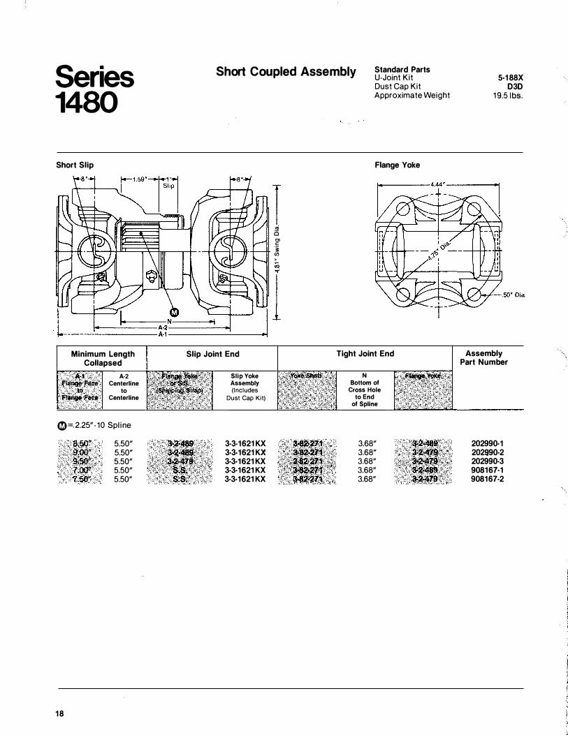
Series 1480
Short Slip
Minimum Length Collapsed
"A·1 Flar!Qe Face to. flange Face
A·2 Centerline
to Centerline
�=,2.25"-10 Spl ine
18
8,50" 9�00" 9,50" i;OQ" 7.50"
5.50" 5.50" 5.50" 5.50" 5.50"
Short Coupled Assembly Standard Parts U-Joint Kit
Slip Joint End
Slip Yoke Assembly (Includes
Dust Cap Kit)
3·3·1621KX 3·3·1621KX 3·3·1621KX 3-3·1621KX 3-3·1621KX
I .,; Ci Ol c 'i: en
Dust Cap Kit Approximate Weight
Flange Yoke
Tight Joint End
N Bottom of
Cross Hole to End
of Spline
3.68" 3.68" 3.68" 3.68" 3.68"
5·188X 030
19.51bs.
Assembly Part Number
202990·1 202990·2 202990·3 908167·1 908167·2
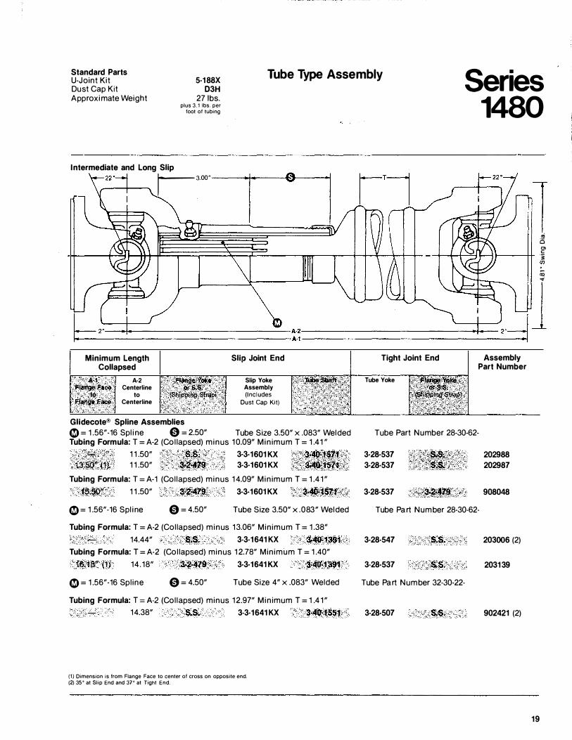
Standard Parts U-Joint Kit 5·188X
D3H 27 1bs.
Tube Type Assembly Series 1480
Du st Cap Kit A pproxim ate Weight
Intermediate and Long Slip
plus 3.1 lbs. per foot of tubing
13.00" r 1 oi 6 C>
..-----1+ ·i (J)
<ii ...
b2l..__,,_ -+--+-J��-----��-----\ --...i __ J,.d l Minimum Length
Collapsed Slip Joint End
A:1 Flan!!le. Face
to Fla!�g$Face
A·2 Centerline
to Centerline
F!ahq,;YOR. Qr'&.S;
• ·• (Snipping Strap) Slip Yoke Assembly (Includes
Dust Cap Kit)
Glidecote® Spline Assemblies 0 = 1 .56"-16 Spl i ne 0 = 2.50" Tube Si ze 3.50" x .083" Wel de d Tubing Formula: T = A-2 ( Col l apse d) minu s 1 0.09" M in imum T = 1 .41 "
·� · 1 1 .50" '$;$, 3·3·1601KX 3�.ftl..f�7t 13.BQ':<1f 1 1 .50" :l-2,479 3·3·1601KX 3�1571 Tubing Formula: T = A-1 ( Col l apse d) minu s 1 4.09" M in imum T = 1 .4 1 "
1�;5Q" 1 1 .50" 3�2�479 3·3·1601 KX . 3·40-"1671
0 = 1 .56"-16 Spl i ne 0 = 4.50" Tube Si ze 3.50" x .083" Wel de d
Tubing Formula: T = A-2 ( Col l apse d) minu s 13.06" Min imum T = 1 .38" 14.44" S.S. 3-3·1641KX 3·40•1391
Tubing Formula: T = A-2 ( Col l apse d) minu s 1 2.78" Min imum T = 1 .40" 16.18" (1) 14 . 18" 3�2-479 3·3·1641KX 3-40·1391
0 = 1 .56"-16 Spl ine 0 = 4.50" Tube Si ze 4" x .083" Wel de d
Tubing Formula:T=A-2 ( Col l apse d) minu s 12.97" M in imum T = 1 .4 1 " 14.38" S.S. 3-3·1641KX 3·40·1551
(1} Dimension is from Flange Face to center of cross on opposite end. (2) 35' at Slip End and 37' at Tight End.
Tight Joint End
Tube Yoke
Assembly Part Number
Tube Part Number 28-30-62-
3·28·537 202988 3-28-537 202987
3-28·537 908048
Tube Part Number 28-30-62-
3-28·547 s.s. 203006 (2)
3-28-537 s.s. 203139
Tube Part Number 32-30-22-
3-28·507 s.s. 902421 (2)
19
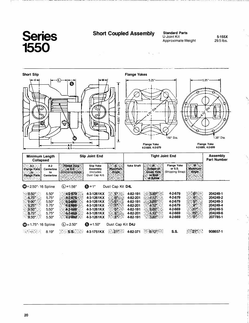
Series 1550
Short Slip
Short Coupled Assembly
Flange Yokes
Flange Yoke 4·2·669, 4·2·679
Standard Parts U-Joint Kit Approximate Weight
5·155X 29.5 1bs.
Flange Yoke 4·2-689, 4·2-699
Minimum Length Collapsed
Slip Joint End Tight Joint End Assembly Part Number
A·1 A·2 Flange Face Centerline to to JJ�f�PIPf!l�t�(lilW) Flange Face Centerline
0=2.50"- 1 6 Sp line ©=1 .56"
8.50" 5.50" 8.75" 5.75" 9.00" 5.50" 9.25" 5.75" 9.50" 5.50" 4�2�669 9.75" 5.75" ,, 4-,2·669 9.50" 5.50" 4�2�689i
0=1.75"· 1 6 Sp line ©=2.50"
8. 1 9" s.s.
20
Slip Yoke Assembly (Includes
Dust Cap Kit)
0=1" Dust Cap Kit D4L
4·3·1261KX 4·82·191 4·3·1261KX 4·82·201 4·3·1261KX 4·82·191 4·3·1261KX 4·82·201 4·3·1261KX 4·82·191 4·3·1261KX 4·82·201 4·3·1261KX 4·82-191
0=1.50" Dust Cap Kit 04J
4·3·1751KX 21, Cf ' . 4·82·371 a:i2"
Flange Yoke or S. S.
(Shipping Strap)
4·2·679 4·2·679 4-2·679 4·2·679 4·2·669 4·2·669 4·2·669
s.s.
:,8'!\ 8,"''', ,,,, a:�b '•' $"'
' 1<:{,�: 'tO" g<i'
21"
204249·1 204249·2 204249·3 204249·4 204249·5 204249·6 207785·1
908657·1
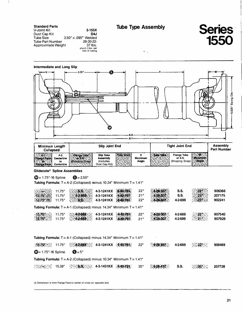
Standard Parts ����t ��X Dust Cap Kit D4J Tube Size 3.50" x .095 "' Welded Tube Part Number 28-30-22-Approximate Weight 37 1bs.
Intermediate and Long Slip
plus 3.3 lbs. per foot of tubing
Tube Type Assembly es Seri 155 0
I oi Ci Ol c: -� en . � "'
" .,;
�-------------------------------A�-------------------------------� I+----------------------------------A·1---------------------------- l
-,
Glidecote® Spline Assemblies
G= 1 .75"-16 Spl ine 0= 2.50" Tubing Formula: T = A-2 (Col lapsed) minus 10.34" M in imum T = 1 .41"
1 1 .75" 1 1 .75" 1 1 .75"
4-3-1241KX 4-3-1241KX 4-3-1241KX
22° 21 ° 22°
Tubing Formula: T = A-1 (Col lapsed) minus 14.34" M in imum T = 1 .41 "
1.�-l"'" 1 1 .75" •• 4·3·1241KX -�v 22° t�tZ'�'r; 1 1 .75" 4·3-1241KX 21 0
Tubing Formula: T = A-1 (Col lapsed) minus 14.34" Min imum T = 1 .41"
1 1 .75"
G= 1 .75"-16 Spl ine
�a-•a 0= 5"
4·3·1241KX •·4(')'1$1 22°
Tubing Formula: T = A-2 (Collapsed) minus 10.34" Min imum T = 1 .41"
1 5.38" s.s. 4-3-1431 KX 4>40•721 35°
(1) Dimension is from Flange Face to center of cross on opposite end.
<�� .. 2' 42�807
Tight Joint End
Flange Yoke or S.S.
(Shipping Strap)
s.s. s.s.
4·2·699
4·2-669 4-2-699
4·2·669
s.s.
22° 21."
embly Ass Part N umber
366 906 207 902
175 241
907 907
540 929
909 469
207 728
21
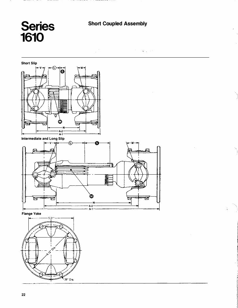
Series 1610
Short Slip
Intermediate and Long Slip V--.j.---l
Short Coupled Assembly
�------------N------------� 1..------_t>::::::��----_-_-_-_-_-_ -_-_ -_ -_A-2 -------_!__....,j
I- A-1--------___:-----l
Flange Yoke
22
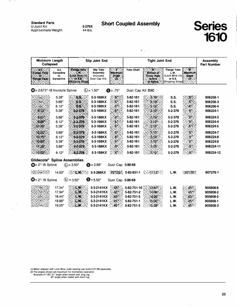
Standard Parts U-Joint Kit Approximate Weight
5·279X 44 1bs.
Short Coupled Assembly
Slip Joint End
Slip Yoke Assembly !Maxi (Includes :�·
Dust Cap Kit) � ', �21···· ,· 0= 2.673"-18 Involute Spl i ne ©= 1.50" 0= .75"
5.38" 5·3·168KX 5.88" 5·3·188KX 6.12" 5-3·198KX 5.38" 5·3·168KX
5.88" 5·3·188KX 6. 12" 5·3·198KX 5.38" 5·3·168KX
5.88" 5·3·188KX 6. 12" 5·3·198KX 5.38" 5·3·168KX 5.88" 5·3·188KX
6.12" 5·3·198KX s.o Glidecote® Spline Assemblies 0= 2"-16 Spl ine ©= 3.50" 0= 2.88" Dust Cap
14.00" t •. w. 5·3·288KX 2.5�126" 0= 2"- 16 Spl ine © = 3.50" 0= 5.50" Dust Cap
17.34" •f.;�-� 5·3·2141KX 45"' 17.94" ) .\.\f/' 5·3·2141KX 45" 18.44" ... �-·· 5·3·2141KX �5� 1 8.88" ···· P?I. 5-3·2141KX 45" 1 9.25" ·�o.w� 5·3-2141KX 46.•
(1) When shipped with Lock W1re, order bearing cap bolts 5·73·109 separately.
(2) The angles shown are maximum for momentary operation. Example 21'/25,' 21' angle when mated with long lug, 25 • angle when mated with short lug.
Tight Joint End
Yoke Shaft · . .• ,,):til\'' ).'.> Flange Yoke ·.89ft9m.of L.W. C:I'Oil$; ftot• (Lock Wire (1))
. t�E� . . or S. S. qf$plll1ec (Shipping Strap
Dust Cap Kit D5C
5·82·161 s.s. 5·82·161 s.s. 5·82·161 s.s. 5-82·161 5·2·379
5·82·161 5·2-379 5·82·161 5·2-379 5·82·161 5·2-279
5-82·161 5·2·279 5-82·161 5·2·279 5·82·161 5·2·279 5·82·161 5·2·279
5·82·161 3 .. 19:" 5·2·279
5·86·68
5·82·831-1 11.12" L.W.
5·86-68
5·82-751·10 13:47'' L.W. 5·82·751·2 14 .. 06°. L.W. 5·82·751·5 14.5$" L.W. 5·82·751·1 15.00'' L.W. 5·82·751·3 15.3'8" L.W.
Series 1610
Assembly Part Number
.w·r Maximum �.!'
906256·1 906256·3 906256·4 906224·1
906224·3 906224·4 906224·5
906224·7 906224·8 906224·9 906224·11
906224·12
30"/35" 907276·1
A5." 905908·6 45" 905908·2 4§i" 905908·5
·:� .. 905908·1 45" 905908·3
23
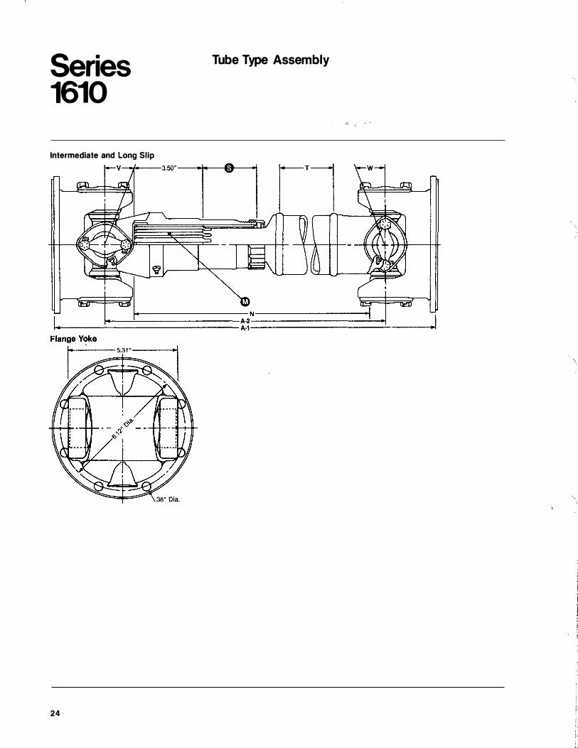
Series 1610
Intermediate and Long Slip
24
Tube Type Assembly
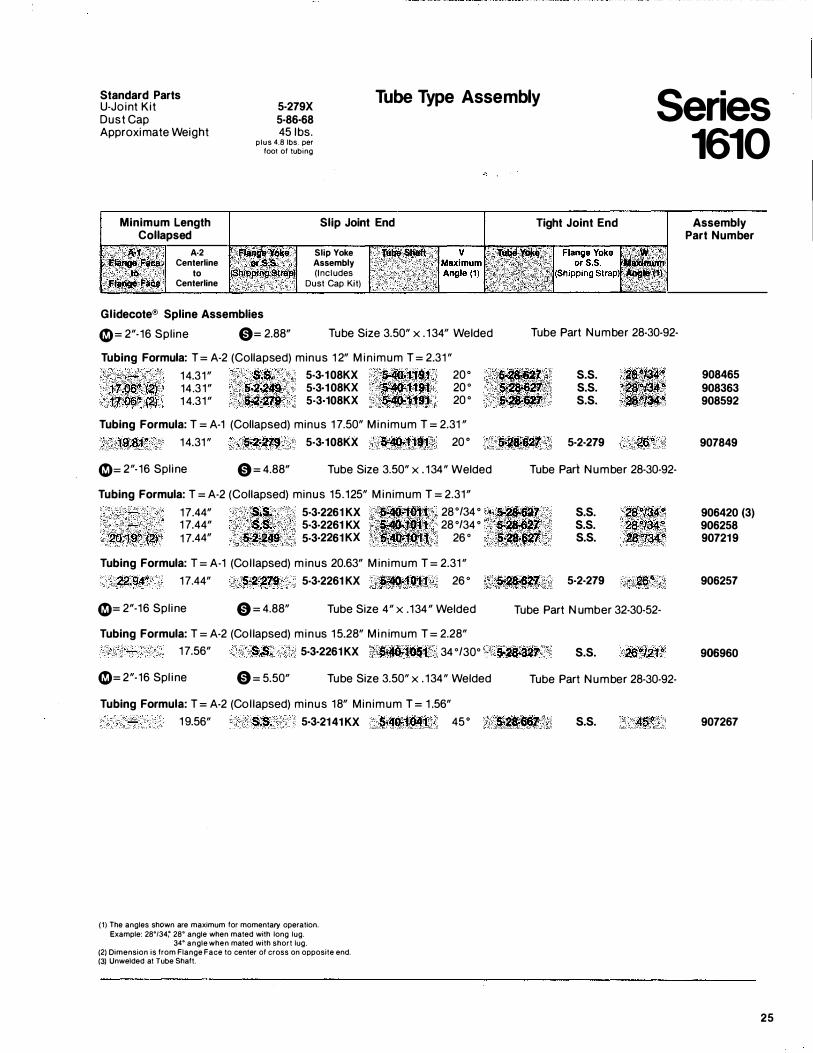
Standard Parts U-Joint Kit Dust Cap Approximate Weight
5·279X 5·86·68 45 1bs.
plus 4.8 lbs. per foot of tubing
Tube Type Assembly Series 1610
Minimum Length Collapsed
Slip Joint End Tight Joint End
A·2 Centerline
to Centerline
Glidecote® Spline Assemblies
Slip Yoke Assembly (Includes
Dust Cap Kit)
(.9= 2"-16 Spline 0= 2.88" Tube Size 3.50" x . 1 34" Welded Tube Part Number 28-30-92-
Tubing Formula: T = A-2 (Collapsed) minus 1 2" M in imum T = 2.31 " 14.31 " S.�. 5·3·108KX . ; $�1:t;91
f1.06" (2) 14.31" �2"24$ 5·3·108KX · ·�1t;fl1 17.00" .(2) 1 4.31 " $'2:;2'19 5·3·108KX $41-1191
20° 20 ° 20 °
Tubing Formula: T = A-1 (Collapsed) minus 1 7.50" M in imum T = 2.31 "
$502, s.s. S'U•$17. s.s. -�;, ... ,; s.s.
1�.$1"' 14.31 " �2:·2:79 5·3·108KX �'t·lf't 20 o &;�' 5·2·279
(.9= 2"-16 Spl ine 0= 4.88" Tube Size 3.50" x . 134" Welded Tube Part Number 28-30-92-
Tubing Formula: T = A-2 (Collapsed) minus 15 .125" M in imum T = 2.31"
17.44" .$.$.' 5·3·2261 KX �41: 1 28°/34 ° <• S;r.2tJ!"fJI'l 1 7.44" ·���. 5·3-2261 KX :<.�. 28 °/34 ° . · $"--�1
2QJ9" {2f 1 7.44" �t·249 5-3·2261 KX .... ·... . .... 26 ° 5-U�ot7 Tubing Formula: T = A-1 (Col lapsed) m inus 20.63" M in imum T = 2.31 "
s.s. s.s. s.s.
22:94" 17.44" 5-2·279 5-3·2261 KX : �'t"011 26 ° �;c�2��·« 5·2·279
(.9= 2"-16 Spl ine 0 = 4.88" Tube Size 4" x .134" Welded Tube Part N umber 32-30-52·
Tubing Formula: T = A-2 (Col lapsed) minus 15.28" M in imum T = 2.28" 17.56" S.S� 5·3·2261 KX .• t��1051 •- 34 °/30° -��--S27 s.s.
(.9= 2"-16 Spl ine 0 = 5.50" Tube Size 3.50" x . 134" Welded Tube Part Number 28-30-92-
Tubing Formula: T = A-2 (Col lapsed) minus 18" Min imum T = 1 .56" 1 9.56" S.S. 5·3·2141 KX .. �r�1Q4'1,: 45o ··��···
(1) The angles shown are maximum for momentary operation. Example: 28•t34: 28• angle when mated with long lug.
34• angle when mated with short lug. (2) Dimension is from Flange Face to center of cross on opposite end. (3) Unwelded at Tube Shaft.
s.s.
Assembly Part Number
908465 908363 908592
907849
906420 (3) 906258 907219
906257
906960
907267
25
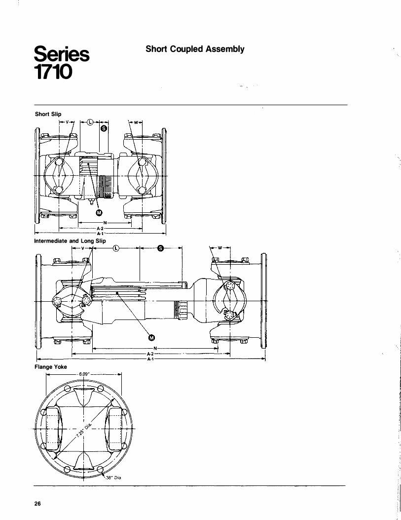
Series 1710
Short Slip
Short Coupled Assembly
Intermediate and Long Slip V-*--� r-��--�--�
�-----------NI------------� t---....!....--------- A-2.-----------___!_--J
t--___ ___; __________ A·1-----------�----l Flange Yoke
26
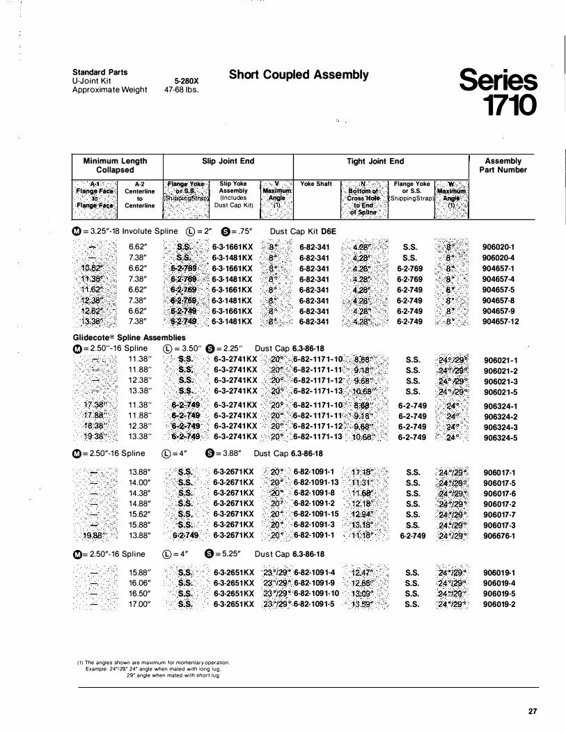
Standard Parts U-Joint Kit Approximate Weight
5·280X 47-68 1bs.
Short Coupled Assembly
Minimum Length Slip Joint End Collapsed
M A·2 Flange Yoke Slip Yoke v Yoke Shaft Flange Face Centerline or.s.s. Assembly Maxlrnum
to to ShippingStrapJ (Includes Angle Flange Face Centerline Dust Cap Kit) (1)
0 = 3.25"-18 Involute Spl ine © = 2" 0= .75" Dust Cap Kit D6E
6.62" s.s. 6·3·1661 KX ao 6-82-341 7.38" s.s. 6-3-1481 KX 8 " 6-82-341
1 0.62" 6.62" 6·2·769 6-3-1661 KX a· 6·82-341 1 1.38" 7.38" 6·2·769' 6·3·1481 KX 8 " 6·82-341 1 1 .62" 6.62" 6·2·769 6-3-1661 KX 8 " 6·82-341 12.38" 7.38" &-2�;76� 6·3·1481 KX 8 " 6·82-341 12.62" 6.62" 6-2�749 6·3·1661 KX a · 6·82-341 13.38" 7.38" 6·2·749 6·3·1481 KX a· 6·82-341
Glidecote® Spline Assemblies 0= 2.50"-1 6 Spl ine © = 3.50" 0 = 2.25" Dust Cap 6.3·86-18
1 1 .38" s.s. 6-3-2741 KX 20" 6-82-1 1 7 1 - 1 0 1 1 .88" s.s. 6-3-2741 KX 20° 6-82-1 1 7 1 - 1 1 1 2.38" s.s. 6-3-2741 KX 20" 6-82-1 171- 12 13.38" s.s. 6-3-2741 KX 20" 6-82- 1 1 71 - 1 3
17.38" 1 1 .38" 6-2-749 6-3-2741 KX 20° 6-82- 1 1 71 - 1 0 1 7.88" 1 1 .88" 6-2-749 6-3-2741 KX 20" 6-82- 1 1 71 - 1 1 1 8.38" 12 .38" 6-2-749 6-3-2741 KX 20"' 6-82-1 1 7 1 - 1 2 19 .38" 13.38" 6-2-749 6-3-2741 KX 20<> 6-82-1 1 71 - 1 3
0= 2.50"-1 6 Spl ine © = 4" 0 = 3.88" Dust Cap 6.3·86-18
13.88" s.s. 6·3·2671 KX 14.00" s.s. 6·3-2671 KX 14.38" s.s. 6·3·2671 KX 14.88" s.s. 6·3·2671 KX 15.62" s.s. 6-3-2671 KX 15.88" s.s. 6-3-2671 KX
1 9.88" 13.88" 6·2·749 6·3·2671 KX
0= 2.50"-16 Spl i ne © = 4" 0 = 5.25"
15.88'' s.s. 6-3-2651 KX 16.06" s.s. 6-3-2651 KX 16.50" s.s. 6·3·2651 KX 17.00" s.s. 6·3·2651 KX
( 1 ) The angles shown are maximum for momentary operation. Example: 24°129,0 24° angle when mated with long lug.
29° angle when mated with short lug.
20 ° 6-82·1091·1 20" 6-82·1 091 ·13 20" 6-82-1091·8 20 ° 6-82-1091·2 20° 6-82·1091 ·15 20° 6-82·1 091 ·3 20" 6-82·1091-1
Dust Cap 6.3·86-18
23"/29" 6-82-1091·4 23"/29" 6-82-1091·9 23"/29 ° 6-82-1091-10 23"/29" 6-82-1091·5
Tight Joint End
N Flange Yoke Bottom of or S.S. Cross Hote ShippingStrap)
to End of Spline
4.28" s.s.
4.28" s.s.
4.28" 6-2-769 4.28" 6-2-769 4.28" 6·2-749 4.28" 6-2-749 4.28" 6-2-749 4.2a" 6-2-749
8.6a" s.s.
9.18" s.s.
9.68" s.s.
10.68" s.s.
8;68" 6-2-749 9:18" 6-2-749 9.68" 6-2-749
1 0 .68" 6-2-749
1 1.18" s.s.
1 1.31 " s.s.
11.68" s.s.
1 2.1 8" s.s.
12.94" s.s.
13.18" s.s.
1 1 .18" 6-2-749
1 2.47" s.s.
12.66" s.s.
1 3.09" s.s.
13.59" s.s.
Series 1710
Assembly Part Number
w Maximl.!rn
Angle (1)
8� 906020·1 8" 906020-4 8" 904657-1 8 " 904657-4 8 . 904657-5 a· 904657-8 8" 904657-9 a · 904657-1 2
24<>/29"' 906021 -1 24"/29°: 906021-2 24"/29" 906021-3 24 " /29" 906021-5
24" 906324-1 24" 906324-2 24" 906324-3 24" 906324-5
24 "/29 " 906017·1 24"129° 906017-5 24"129" 906017-6 24"/29" 906017·2 24"/29" 906017·7 24"/29" 906017·3 24"/29" 906676-1
24 "/29" 90601 9·1 24 "/29" 906019-4 24 "/29" 906019·5 24 "/29" 906019·2
27
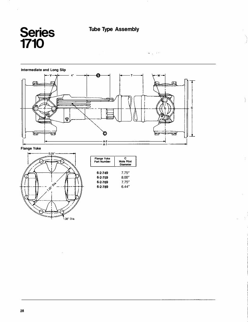
Series 1710
Intermediate and Long Slip
Tube Type Assembly
1_---�=========A-2---------.1 .- A-1-----------____: ___ --l
Flange Yoke
28
Flange Yoke Part Number
6·2·749 7.75" 6·2·759 8.00" 6·2·769 7.75" 6·2·789 6.44"
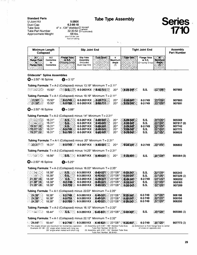
Standard Parts U-Joint Kit Dust Cap Tube Size Tube Part Number Approximate Weight
5-280X 6.3·86-18
4" X . 1 34" Welded } ( except where
32-30-52- Footnoted) 68 1bs.
plus 5.5 lbs. per foot of tubing
Tube Type Assembly Series 1710
Minimum Length Collapsed
Slip Joint End Tight Joint End Assembly Part Number
M Flange � •• , ·� .
Flange Face;
A·2 Centerline
to Centerline
Flai:lge Yoke Slip Yoke Clfs.�, /f Assembly )Shipping $tr��J, (Includes l£ Dust Cap Kit)
Glidecote® Spline Assemblies 4irJ = 2.50"-16 Spl ine 0 = 3. 12"
Tubing Formula: T = A-2 (Col lapsed) minus 13. 19" Min imum T = 2. 1 1 " 15.50" $.$. 6·3·2631 KX '6•40:•t1:1 ' 20 o ,,,lt�fJ,;Mf/
Tubing Formula: T = A-1 (Collapsed) minus 19.19" Min imum T = 2. 1 1 "
21.50" 15.50" ·��749 � 1 6·3·2631 KX {'f 20° 21 .50" 15.50" 6·2•7$9" (� 6·3·2631 KX 1 20°
4irJ= 2.50"-16 Spline 0 = 3.88"
Tubing Formula: T = A-2 (Collapsed) minus 1 4" M in imum T = 2.3 1 " 16.31 " S;$. 6·3·2671 KX 6• �{ ... ·. 20 ° 1 6.31 " $�& 6·3·2671 KX ·f$.· . 20 ° 1 6.31 " s�s� 6·3·2671 KX 2oo 1 6.31 " �2rl4il 6·3·2671 KX 20° 16.31 " 6•2·789 6·3·2671 KX 20 °
Tubing Formula: T = A-1 (Collapsed) minus 20" M in imum T = 2.31 "
22.31" 16.31 " 6·2·749 6·3·2671 KX �4().541 20 °
Tubing Formula: T = A-2 (Col lapsed) minus 1 4.25" Min imum T = 2.31 "
1 6.56" S.S. 6·3·2671 KX fi..40.63f 20 °
4irJ= 2.50"-16 Spl ine 0= 5.25"
Tubing Formula: T = A-2 (Col lapsed) minus 16.03" Min imum T = 2.35"
21.38" (4} 21 .38" (4) 21.38" (4)
18.38" s�s. 6·3·2651 KX s-4o�s21 23 °/28° 18.38" $.S. 6·3·2651 KX 6-40-521 23 °/28° 1 8.38" S.S. 6·3·2651 KX $.4f)'·52't. 23 °/28 ° 1 8.38" 6�2•749 6·3·2651 KX '&<4Q.$21 . 23 °/28 ° 18.38" 6·2·759 6·3·2651 KX �40-521 23 °/28 °
Tubing Formula: T = A-1 (Col lapsed) minus 22.03" Min imum T = 2.35"
24.38" 18.38" �2•749 6·3·2651 KX 6-40·521 23 °/28 ° 24.38" 18.38" �2·759 6·3·2651 KX 6-40.521 23 °/28 ° 24.38" 1 8.38" �2·789 6·3·2651 KX �40o521 23 °/28°
Tubing Formula: T = A·2 (Collapsed) minus 16 . 12" M in imum T = 2.32"
18.44" S.S. 6·3·2651 KX 6·40�621 23 °/28°
Tubing Formula: T = A-1 (Col lapsed) minus 22. 1 2" Min imum T = 2.32"
24.44" 18.44" �2·749 6·3·2651 KX �4o-621 23 °/28 °
e�2a .. �1
•�<�·llQJ:
Ei�28447 6�$.�7 ·�·28-$47 �28<�1: 6'2.347
· :s-:��347 �2�$47 . 6·28-�7:
�28·407
�28-407
s.s.
6·2·749 22 !!• 6·2·749 ·.22
s.s. s.s.
6·2·749 s.s. s.s. 2:all/$;�.
6·2·749 2,2.�/29� .
s.s. 20"l29�
s.s. 2210129.� s.s. 22"129"
6·2·749 22°129"5 s.s. 22"�o s.s. 22"129"
6·2·749 22"12�" 6·2·749 22"129" 6·2·749 22''129"
s.s. 20"129°
6·2·749 20"129" { 1 ) The angles shown are maximum tor momentary operation.
Example 23"'/28 ° . 23° angle when mated with long lug, 28"' angle when mated with short lug
(2) Assembly with 4.09" • . 1 80" Welded Tube S1ze. Tube Part Number 32-30-72-
(4) Otmension ts from flange face to center of cross on oppostte end
(3) Assembly with 4.50"-. 134" Welded Tube Size. Tube Part Number 36-30-62-.
907882
907883 907691
905569 90781 7 (2) 907742 907775 908628
906802
905564 (3)
905343 907229 (2) 906202 908165 907289
906198 906156 906200
905566 (3)
907773 (3)
29
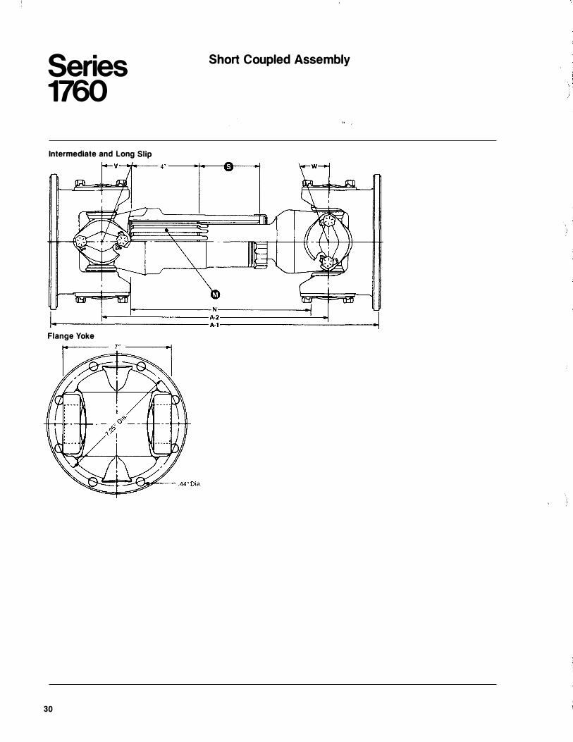
Series 1760
Intermediate and Long Slip
Flange Yoke
30
Short Coupled Assembly
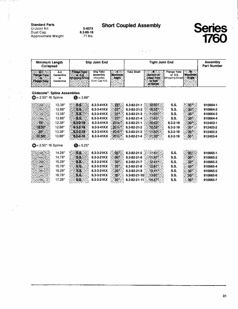
Standard Parts U-Joint Kit 5·407X
6.3·86·18 71 1bs.
Short Coupled Assembly Series 1760
D ust Cap Approximate Weight
Slip Joint End
Glidecote® Spline Assemblies 0::::: 2.50"·16 Spl i ne
1 2.38" 1 2.88" 1 3.38" 13.88" 1 2.38" 1 2.88" 1 3.38" 13.88"
0= 2.50"·16 Spl ine
14.28" 14.78" 15.28" 15.78" 1 6.28" 1 6.78" 1 7.28"
0 = 3.88"
6.3·3·41 KX 6.3·3·41 KX 6.3·3·41 KX 6.3·3·41 KX 6.3·3·41 KX 6.3·3·41 KX 6.3·3·41 KX 6.3·3·41 KX
0= 5.25"
6.3·3·21 KX 6.3·3·21 KX 6.3·3·21 KX 6.3·3·21 KX 6.3·3·21 KX 6.3·3·21 KX 6.3·3·21 KX
; ll' , ,, . .. ·��''•. an.� . . ' ','\';' ao·" $Ill>
/��
Yoke Shaft
6.3·82·21 ·1 6.3·82·21·2 6.3·82·21 ·3 6.3·82·21 ·4 6.3·82·21·1 6.3·82·21·2 6.3·82·21 ·3 6.3·82·21·4
6.3·82·21 ·5 6.3·82·21 ·6 6.3·82·21-7 6.3·82·21 ·8 6.3·82·21·9 6.3·82·21·1 0 6.3·82·21-11
Tight Joint End
$1;41*'·· •. · 1tll1" 1·�,4;jli 12,91.'' 1�.41/l/. 13'.9�if 14,41tl'
Flange Yoke ,, W • ;, or S. S. 'lltflxitll�
• (Shipping Strap) • · ·. :A�"· ··�
s.s. s.s. s.s. s.s.
6.3·2·19 6.3·2·19 6.3·2·19 6.3·2·19
s.s. s.s. s.s. s.s. s.s. s.s. s.s.
Assembly Part Number
910664·1 910664·2 910664·3 910664·4 912403·1 912403·2 912403·3 912403·4
910665·1 910665·2 910665·3 910665·4 910665·5 910665·6 910665·7
31
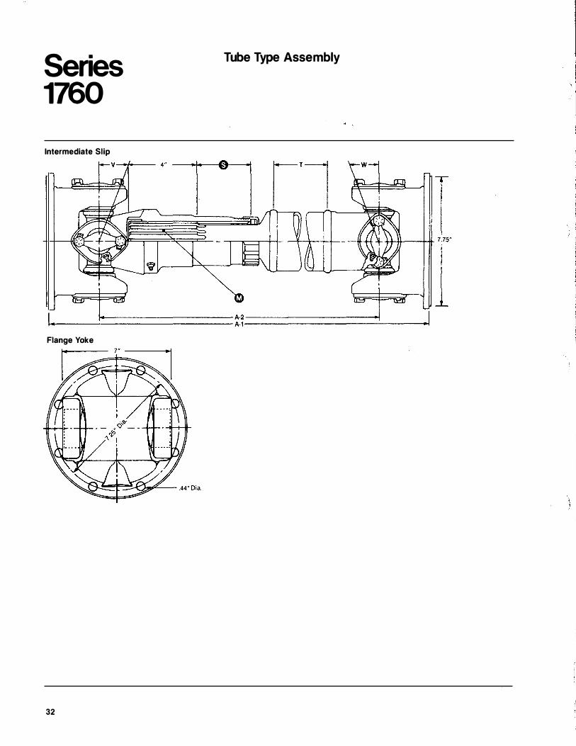
Series 1760
Intermediate Slip
Tube Type Assembly
I ---�=============== A- 2 ---------1 ,_. A·1 --------�---
Flange Yoke
32
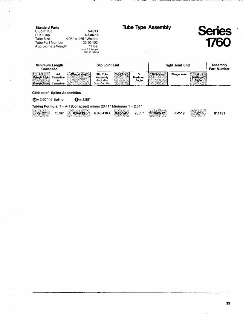
Standard Parts U-Joint Kit Dust Cap
5·407X 6.3·86-18
4.06" x . 165" Welded
Tube Type Assembly
Tube Size Tube Part Number Approximate Weight
Minimum Length Collapsed
A�1 . A·2 FUtittJe F� Centerline , . . . t� ,- · / to Fclal!fie Fa� Centerline
32-30-102-71 1bs.
plus 5.9 lbs. per foot of tubing
Slip Joint End
Slip Yoke Assembly (Includes
Dust Cap Kit)
Glidecote® Spline Assemblies
0= 2.50"-16 Spline 0 = 3.88"
Tubing Formula: T = A-1 (Col lapsed) minus 20.41 " M in imum T = 2.31 "
22.72"' 15.96" 6.3·3·41 KX 6i40-S�t
Tight Joint End
Flange Yoke
Series 1760
Assembly Part Number
91 1 1 31
33
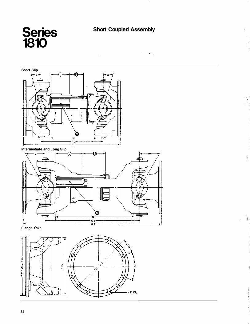
Series 1810
Short Slip
I. Intermediate and Long Slip
v
34
Short Coupled Assembly
.I
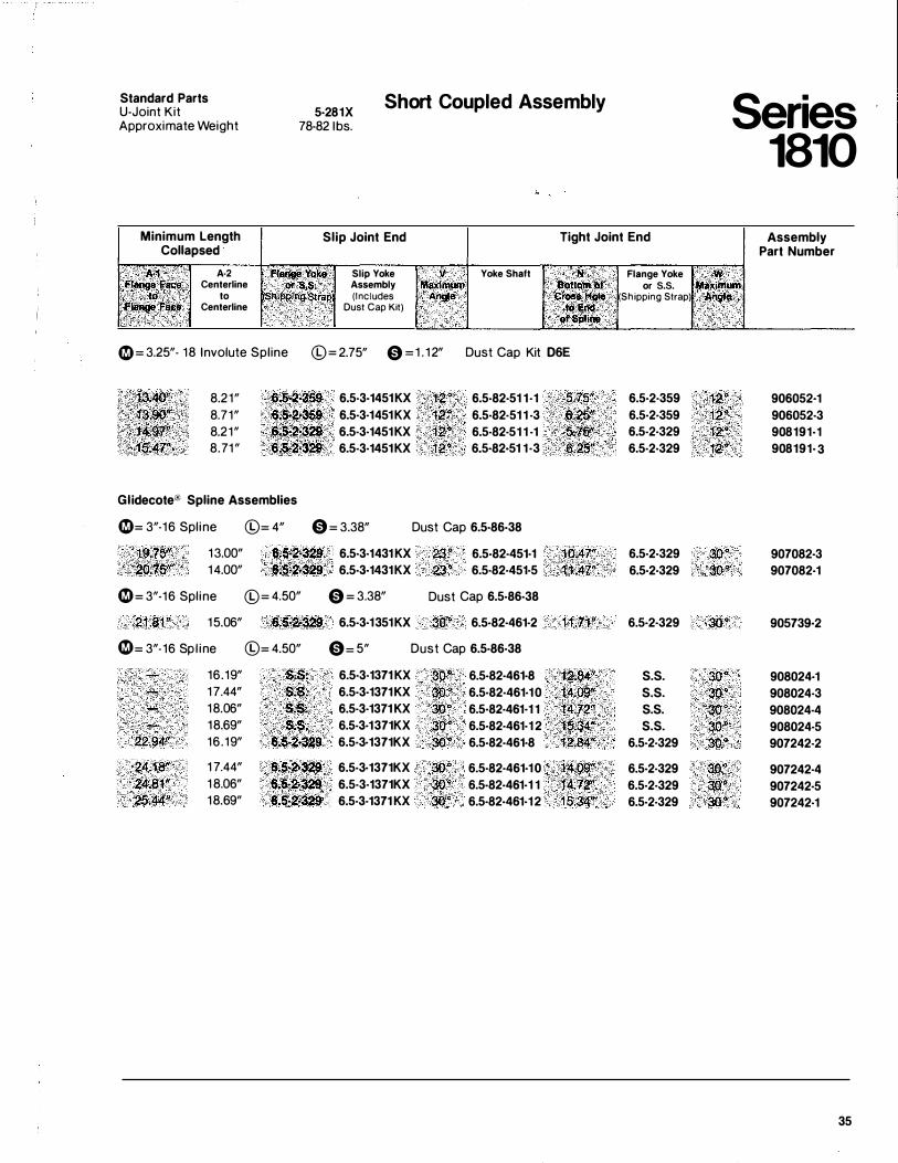
Standard Parts U-Joint Kit Approximate Weight
5-281X 78-82 1bs.
Short Coupled Assembly Series 1810
Minimum Length Collapsed
Slip Joint End Tight Joint End Assembly Part Number
�A"1 �,_nge'l!'a� ; '� .• to ... f1' ·�F�Jee
A·2 Centerline
to Centerline
Fta.�e Yoke Slip Yoke Qr S'S, Assembly Shipplng Strap (Includes
Dust Cap Kit)
v MIIXimum Angle
Yoke Shaft N aottom.;of
CrO$liHQte to J:nd ot$J,IIil\e
0 = 3.25"- 18 Involute Spline (0= 2.75" 0 =1 . 12" Dust Cap Kit 06E
�:13.40'� 8.21" 6.��-359 6.5-3-1451 KX 12'" 6.5-82-51 1 -1 5.75'' [·�t�_gzyt 8.71" 6.5-2459 6.5·3·1451KX 12� 6.5·82·51 1 ·3 s.2stt ii ·'t4,97" <; ·�- 8.21" 6���:3�9 6.5·3·1451KX • 12"' ' 6.5·82·51 1 -1 fic7511 '.'15.4'7" 8.71 " 6$-�..329 6.5·3·1451KX 12" 6.5·82·51 1 ·3 6 .. 25"
Glidecote® Spline Assemblies
0= 3"-16 Spl ine ©= 4" 0 = 3.38" Dust Cap 6.5·86-38
19.75� 13.00" 6.5-��329 6.5·3·1431 KX 23 .. 6.5-82·451·1 1.0.47" ,20.75" 14.00" ·6.'5·2·329 6.5·3·1431KX 23 � 6.5·82·451·5 . ·1�.411' 0 = 3"-16 Spl ine ©= 4.50" 0 = 3.38" Dust Cap 6.5-86-38
21.81ft 15.06" ().5<20\3�9 6.5·3·1351KX 30" 6.5-82·461-2 11,71" 0 = 3"-16 Sp l ine ©= 4.50" 0= 5" Dust Cap 6.5·86·38
16.19" s.s. 6.5·3·1371 KX 30" ' 6.5-82·461·8 12JW" 17.44" S.S; 6.5·3·1371 KX so· 6.5·82·461·1 0 14.09'' 18.06" s.s. 6.5·3·1371 KX 3o" 6.5·82·461·1 1 l�H2" 18.69" s.s. 6.5·3·1371KX .30" 6.5·82·461·1 2 15.�.
22.94" 16 . 19" 6.5-2"329 6.5·3·1371KX 30� 6.5-82-461·8 12.84"
24.18" 1 7.44" 6.5-2.3�9 6.5-3·1371KX 30" 6.5·82·461·1 0 1409'" 24.81" 1 8.06" 6.5-,2'3�9 6.5·3·1371KX 30" 6.5-82-461·1 1 . .. 111: 12"• r 25.44" 18.69" 6.5-�·329 6.5·3·1371 KX 30" 6.5·82-461·12 15.34"
Flange Yoke · W or s.s. Ml!Ximum
(Shipping Strap) Angle ··
6.5·2·359 12" 6.5·2·359 12" 6.5·2·329 12" . 6.5·2·329 . 12"
6.5·2-329 30" 6.5·2·329 30�
6.5·2·329 30"
s.s. 30"
s.s. 30" s.s. 30" s.s. 30"
6.5·2·329 sQ"' 6.5·2·329 :�9" 6.5·2·329 30 " 6.5·2·329 30"
906052·1 906052·3 908191·1 908191· 3
907082·3 907082·1
905739·2
908024·1 908024·3 908024·4 908024·5 907242·2
907242·4 907242·5 907242·1
35
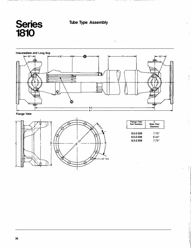
Series 1810
c
36
Tube Type Assembly
Flange Yoke Part Number
6.5·2·329 6.5·2·349 6.5·2·359
c Male Pilot Diameter
7.75" 6.44" 7.75"
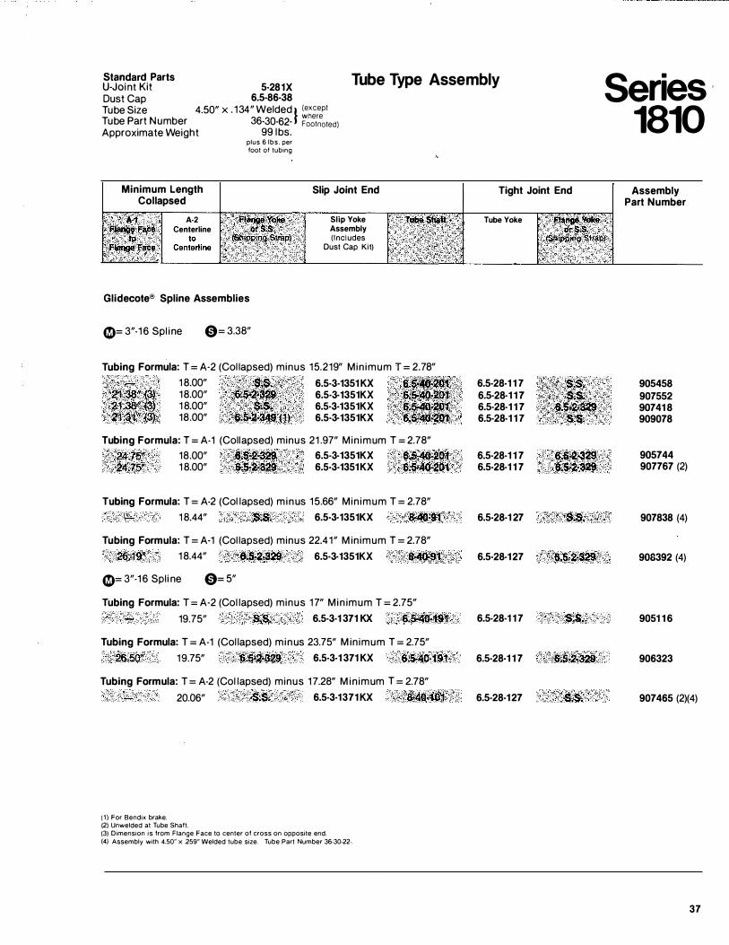
���i��r�larts 5-281X Tube Type Assembly
Dust Cap 6.5·86·38 Tube Size 4.50" x . 134" Welded l (except T b where u e Part Number 36-30·62· Footnoted) Approximate Weight 99 lbs.
plus 6 lbs. per foot of tubing
Minimum Length Collapsed
Slip Joint End Tight Joint End
,c·· · < A·�· A·2 Slip Yoke Assembly (Includes
;�fi.fange, Fa�. . Centerline ) .· • • to i a'angeFace Dust Cap Kit)
Glidecote® Spline Assemblies
0= 3"-1 6 Spl ine 0= 3.38"
Tubing Formula: T = A-2 (Col lapsed) minus 15.219" Min imum T = 2.78" 1 8.00" \ • Si�� 6.5·3·1351 KX 18.00" .·��5���#9 .. ····· 6.5·3·1351KX 1 8.00" $•�· . < 6.5·3·1351KX 18.00" . (1�&;2,349:{1) 6.5·3·1351KX
Tubing Formula: T = A-1 (Collapsed) minus 21 .97" Min imum T = 2.78" · . 24(l'Ql' 18.00" .. 6-2•�29 6.5·3·1351KX . . $.5-4��0�
24;75" 1 8.00" �·2·329 6.5·3·1351KX <6;5-'�0r�:t Tubing Formula: T = A-2 (Col lapsed) minus 15.66" Min imum T = 2.78"
1 8.44" S.$. 6.5·3·1351KX &!40'�91' Tubing Formula: T = A·1 (Col lapsed) minus 22.41" M in imum T = 2.78"
25,19" 1 8.44" 6.$-2!329 6.5·3·1351KX �;9l 0= 3"-1 6 Spl i ne 0= 5"
Tubing Formula: T = A-2 (Col lapsed) minus 17" M in imum T = 2.75"
19. 75" .S,$. 6.5·3·1 371 KX 6.�:4t.<t91 Tubing Formula: T = A-1 (Col lapsed) minus 23.75" M in imum T = 2.75"
26.5()" 19.75" · · 6.$1.2�329 6.5·3·1 371 KX 6,5:.J.IO,.i9t Tubing Formula: T = A-2 (Col lapsed) minus 17.28" M in imum T = 2.78"
20.06" S�S. 6.5·3·1371 KX '"8,lf4Q.jQ:1 • .'
( 1 ) For Bendix brake. (2) Unwelded at Tube Shaft. (3) Dimension is from Flange Face to center of cross on opposite end. (4) Assembly with 4.50" x .259" Welded tube size. Tube Part Number 36·30·22·.
Tube Yoke
6.5·28·1 1 7 6.5·28·1 1 1 6.5·28-1 1 7 6.5·28-1 1 7
6.5·28-1 1 7 6.5·28-1 1 7
6.5·28·1 27
6.5·28·127
6.5·28-1 1 7
6.5·28·1 1 7
6.5·28·127
6·�·2�� ·e: • .s-.2-329
.$�$.
6{5-2-329. '
$.$.
Series · 1810
Assembly Part Number
905458 907552 90741 8 909078
905744 907767 (2)
907838 (4)
908392 (4)
9051 1 6
906323
907465 (2)(4)
37
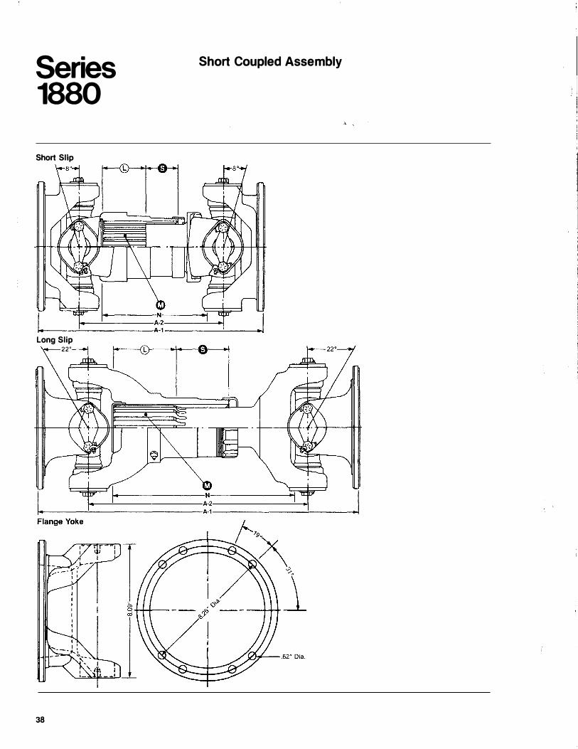
Series 1880
Short Slip
Short Coupled Assembly
1+----...!._-----,A-1 -----!---..1
Long Slip 22"
38
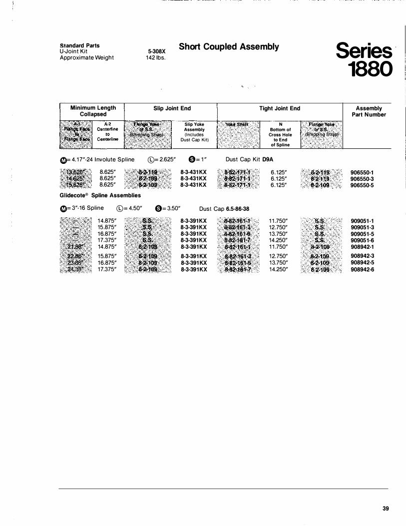
Standard Parts U-Joint Kit Approximate Weight
5-308X 142 1bs.
Short Coupled Assembly
Minimum Length Collapsed
41)= 4.1 7"-24 I nvolute Spl ine
8.625" 8.625" 8.625"
Glidecote® Spline Assemblies
Slip Joint End
©= 2.625"
Slip Yoke Assembly (Includes
Dust Cap Kit)
0= 1 "
8-3-431 KX 8-3-431 KX 8-3-431 KX
Yoke Shaft
Tight Joint End
N Bottom of
Cross Hole to End
of Spline
Dust Cap Kit D9A
8·&2·171-1 8�82-171•1 8-82·171�1
6.125" 6.125" 6.125"
41)= 3"-16 Spline ©= 4.50" 0= 3.50" Dust Cap 6.5·86-38
1 4.875" 15.875" 1 6.875" 17.375" 14.875"
15.875" 1 6.875" 17.375"
.. ��s� . . z:1 :·C:I:. .
· .. · · ·�··��······.· · · . · ·�*��· ��fi:l . �2:�10$
8·3-391 KX 8·3·391 KX 8·3·391 KX 8·3·391 KX 8·3·391 KX
8·3·391 KX 8·3·391 KX 8·3·391 KX
8-82·161-1 1 1 .750" Jf��·161'�� 12.750" 8••2·1'61�6 13.750" 8�2-161·7 14.250" &'82·161-1 1 1 .750"
s"'a2�1'61�� 12.750" 8•&2·16Hf ' · 13.750" 8·82•1$1:7 14.250"
Series · 1880
Flange Yoke. orS;S. . (Snipping Strap)
8·2·119 8-2-119 8•2·109
S;S. s.s. s.s. s.s.
8-2·109
8·2409 8-2·109 8-2·109
Assembly Part Number
906550·1 906550-3 906550-5
909051 -1 909051 ·3 909051 ·5 909051·6 908942·1 908942·3 908942·5 908942-6
39
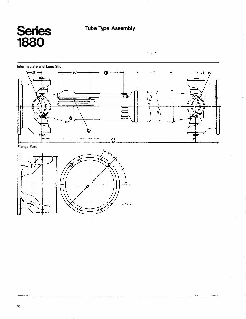
Series 1880
Intermediate and Long Slip
Tube Type Assembly
j-------------A-2 ---------------1 r--c---.:..._-----------A-1 --------------L __ __J Flange Yoke
40
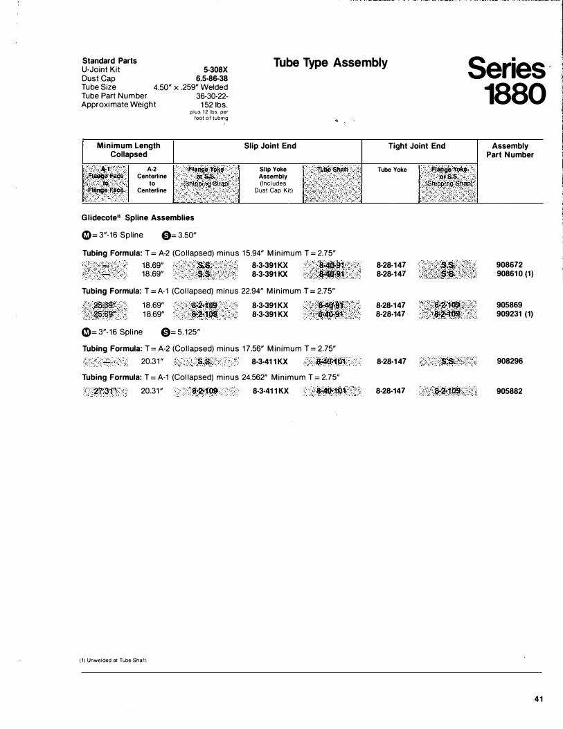
Standard Parts U-Joint Kit Dust Cap
5-308X 6.5-86-38
4.50" x .259" Welded
Tube Type Assembly Series 1880
Tube Size Tube Part Number Approximate Weight
Minimum Length Collapsed
A-1 Fla119&·Face . to Flange Face
A·2 Centerline
to Centerline
36-30-22-152 1bs.
plus 1 2 lbs. per foot of lubing
Fla!ltle Yol<e ors.s.
(Shipping Strap)
Glidecote® Spline Assemblies
0 = 3"·16 Spline 0= 3.50"
Slip Joint End
Slip Yoke Assembly (Includes
Dust Cap Kit)
Tube Shaft
Tubing Formula: T = A-2 (Col lapsed) minus 15.94" M in imum T = 2.75" 18.69" S.S; 8·3·391 KX 8-40.91 18.69" S.S. 8·3·391 KX '���·9'1
Tubing Formula: T = A-1 (Col lapsed) minus 22.94" M in imum T = 2.75"
25Ji9" 18.69" 8·2-109 8·3·391 KX '8�4o.91 25.69" 1 8.69" 8-2•109 8·3·391 KX ·�0:-91
0= 3"-16 Spl ine 0= 5.125"
Tubing Formula: T = A·2 (Col lapsed) minus 17.56" M in imum T = 2.75"
20.31 " S.S. 8·3·41 1 KX 8·4o.101 Tubing Formula: T = A-1 (Col lapsed) minus 24.562" Min imum T = 2.75"
2'7�31'1 20.31 " 8•2·109 8-3-41 1 KX 8·40·101
( 1 ) Unwelded at Tube Shaft.
Tight Joint End
Tube Yoke
8·28·147 8·28-147
8·28-147 8-28-147
8·28-1 47
8-28-147
Flan.g!J Yoke. or.s.s.
iS!llppin� strap)
8-2•'t09 , .J�2�109 . .
Assembly Part Number
908672 90861 0 (1)
905869 909231 (1)
908296
905882
41
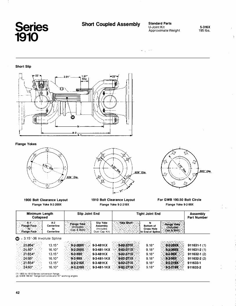
Series 1910
Short Coupled Assembly Standard Parts U-Joint Kit Approximate Weight
5-316X 1 95 1bs.
Short Slip
�--------N ----------�
I -------�==========�A�-2------------� c. A-1--------------�
Flange Yokes
1 900 Bolt Clearance Layout Flange Yoke 9-2-269X
Minimum Length Collapsed
A·1 A-2 Flange Face Centerline
to to Flange Face Centerline
� = 3.1 5"-36 Invol ute Spl i ne
21 .654" 13. 15" 24.60" 16.10" 21 .654" 1 3. 15" 24.60" 1 6. 10" 21 .654" 13. 15" 24.60" 16.10"
( 1 ) 1 900 to 1 9 1 0 Senes converston flange.
1 91 0 Bolt Clearance Layout Flange Yoke 9·2-219X
Slip Joint End
Flange Yoke Slip Yoke Yoke Sbaft Assembly (Includes ( Includes Cap & Bolt)
Dust Cap Kit)
9·2·269X 9·3·481 KX 9·82�271X 9·2·269X 9-3-481 ·1 KX 9·82·271X 9·2·99X 9·3·481 KX 9·82·271X 9·2·99X 9·3·481·1 KX 9·82·211X 9·2·219X 9-3-481 KX 9·82-271X 9·2·219X 9-3-481-1 KX 9·82·211X
(2) GWB 1 90.50" flange bolt ctrcle and 15° workmg angles.
42
.640" 0!!.,_
For GWB 1 90.50 Bolt Circle Flange Yoke 9·2·99X
Tight Joint End Assembly Part Number
N flaJ\.ga Yo�e
Bottom of Cross Hole (inc;l4c�
to End of Spline Cap & aottf
9.18" '9•'2·268 91 1 631-1 (1 ) 9 . 18" ·t-�·2$$'� 91 1631-2 (1 ) 9.18" 9-2�$9}{ 91 1 632·1 (2) 9.18" 9·2;.$$cX 91 1 632-2 (2) 9.18" 9•2•21JX 911633-1 9.1 8" 9-2·219X' 911633·2
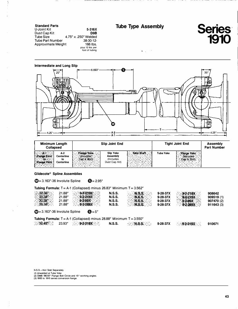
Standard Parts U-Joint Kit Dust Cap Kit Tube Size
5·316X 098
4. 75" x .250" Welded
Tube Type Assembly
Tube Part Number Approximate Weight
38-30-1 2· 1 66 1bs.
plus 1 2 lbs. per foot of tubing
Intermediate and Long Slip r6.693"
Minimum Length Collapsed
A·1 A·2 Flange Yoke · Flange .Face Centerline (Inc tudes
to to Cap & Bolt) Flange Face Centerline
Slip Joint End
Slip Yoke Assembly (Includes
Dust Cap Kit)
Glidecote® Spline Assemblies
0= 3.163"-36 Involute Spl ine 0= 2.95"
Tub.e Shaft
Tubing Formula: T = A-1 (Col lapsed) minus 26.83" M in imum T = 3.562" 30.38� 21 .88" 9-2·219X N.S.S. N.S.S. 30.-38" 21 .88" 9·2�219X N.S.S. N,S.S. 30:36" 21 .88" 9·2·99X N.S.S. N.S.S. 30.38" 21 .88" 9·2·269X N.S.S. N.S.S.
0= 3.163"·36 Involute Spl ine
Tubing Formula: T = A-1 (Col lapsed) minus 28.88" M in imum T = 3.550" 32.43" 23.93" 9·2�219X N.S.S. N.S.S�
N.S.S.-Not Sold Separately
(1) Unwelded at Tube Yoke (2) GWB 190.50' Flange Bolt Circle and 1 5 ° working angles. (3) 1900 to 1910 series conversion flange.
Tight Joint End
Tube Yoke
9·28·37X 9·28·37X 9-28-37X 9-28-37X
9·28·37X
Fll'l9fi Y<!ke {fllcfuctes
Cap & Bolt)
$.2·219X •·2·219X 9.2·99X !);.2·26$X
9-2·219X
Series 1910
Assembly Part Number
908642 90951 9 (1 ) 907470 (2) 91 1 643 (3)
910671
43
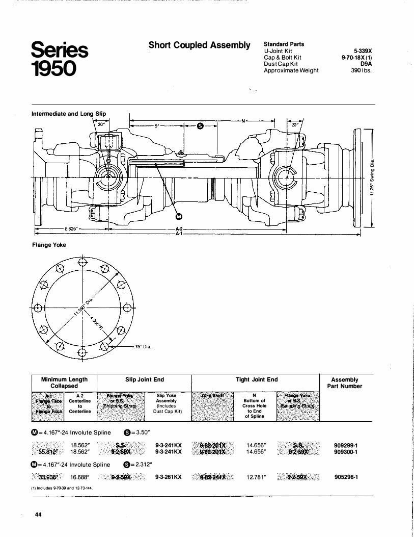
Series 1950
Intermediate and Long Slip
Flange Yoke
Minimum Length Collapsed
A-1 Flange Face
to Fl .. Face
A·2 Centerline
to Centerline
0 = 4.167"-24 Involute Spline
35;812" 1 8.562" 18.562"
0= 4.167"-24 Involute Spl i ne
33.938" 1 6.688"
(1) Includes 9-71}39 and 1 2·73-144.
44
Short Coupled Assembly Standard Parts U-Joint Kit
Slip Joint End
0= 3.50"
s.s. 9*2·59X
0= 2.31 2"
Slip Yoke Assembly (Includes
Dust Cap Kit)
9·3·241 KX 9·3·241 KX
9·3-261 KX
··. ·· ·... .
· .. . · ..
Cap & Bolt Kit Dust Cap Kit Approximate Weight
Tight Joint End
N Bottom of
Cross Hole to End
of Spline
1 4.656" 1 4.656"
1 2.781"
Flange.Y�!J ·····. .,-s,s; ·. > {SitipPi�g: �}r4P1
. . .
5-339X 9·70-18X (1)
D9A 390 l bs.
Assembly Part Number
909299-1 90930()..1
905296-1
l oi 0 Ol c � �
J
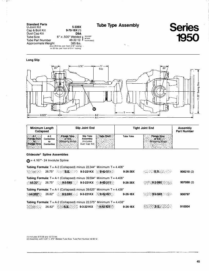
Standard Parts U-Joint Kit 5-339X Cap & Bolt Kit 9-70-18X (1) Dust Cap Kit D9A Tube Size 6" X .500" Welded l (except
Tube Part Number 48-32-12- r :"c,����tedl
Approximate Weight 385 lbs.
Long Slip
plus 29.5 lbs. per foot of 6" tubing or 20 lbs. per foot of 5'14'' tubing.
Tube Type Assembly
Minimum Length Slip Joint End Tight Joint End Collapsed
M A·2 Flange Yoke 'Flange Face Centerline or s.s. •... . ·. ·. b;l to (Shipping Strap) Ffange Face Centerline
Glidecote® Spline Assemblies
0= 4.167"- 24 Involute Spl ine
Slip Yoke Tube Sbaft Tube Yoke Assembly ( Includes i. Dust Cap Kit)
•·
Tubing Formula: T = A-2 (Col lapsed) minus 22.344" M in imum T = 4.406" 26.75" S.S. 9-3-221 KX 9-42·31 1 9-26-38X
Tubing Formula: T = A-1 (Col lapsed) minus 39.594" M in imum T = 4.406" .44.00" 26. 75" 9-2·59X 9·3·221 KX 9>42·311 9-26-38X
Tubing Formula: T = A-1 (Col lapsed) m inus 39.625" Min imum T = 4.438" 44.Q62ll 26.82" 9>2·59X 9·3-221 KX 9·42·421 9-26-18X
Tubing Formula: T = A-2 (Col lapsed) minus 22.375" M in imum T = 4.438" 26.82" S�S. 9-3·221 KX 9·42·421 9-26-18X
(1) Includes 9·70·39 and 12·73·144. (2) Assembly with 5.25" x .375" Welded Tube Size. Tube Part Number 42·31).12·.
Flange.Y()ke or �:s' . (�hil)ping strap)
s.s.
9·2·59X
9·2·59X
s.s.
Series 1950
Assembly Part Number
. ·.
906210 (2)
907088 (2)
906797
910004
1 "' 0 0> c:: ·� (J)
� ::
J
45
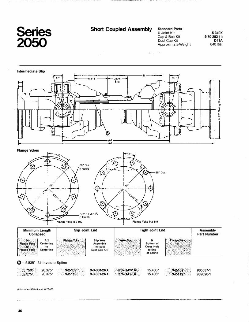
Series 2050
Short Coupled Assembly Standard Parts U-Joint Kit 5·340X
9·70·28X (1) D11A
840 lbs.
Intermediate Slip
Flange Yokes
Minimum Length Slip Joint End Collapsed
A·1 A·2 Flange Yoke Slip Yoke Flange Face Centerline Assembly
to to (Includes Flange Face Centerline Dust Cap Kit)
0 = 5.835"· 34 Involute Spl ine
33.750" 39.375"
20.375" 20.375"
(1} Includes 9·70·49 and 16-73·156.
46
9·2·109 9·2·119
9-3·331·2KX 9-3·331 ·2KX
Cap & Bolt Kit Dust Cap Kit Approximate Weight
1 ... 0 Cl c
-+--+-Hf-#-tt �
.88" Dia.
Flange Yoke 9·2·119
Yoke Shaft
9·82·141·1X 9·82·141·1X
···.
Tight Joint End
N Bottom of
Cross Hole to End
of Spline
1 5.406" 15.406"
flange Yoi(E!
9·2·109 9-2·119
:
:n N :!
J
Assembly Part Number
905537·1 909020·1
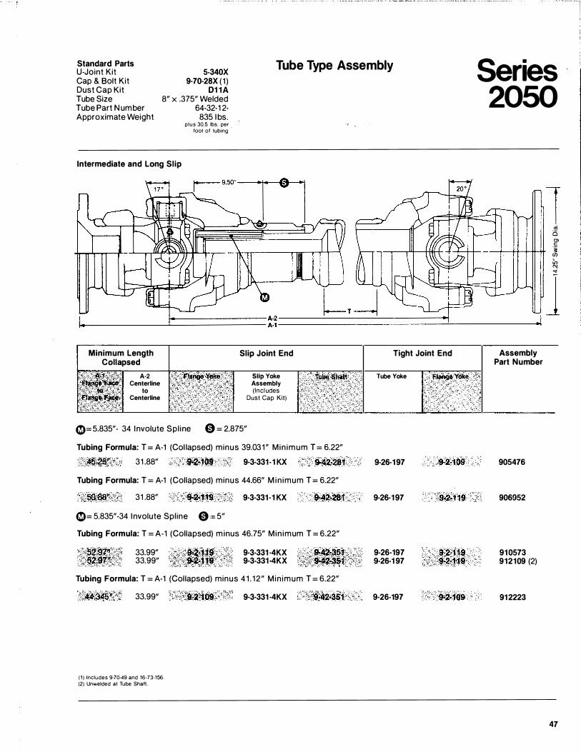
Standard Parts U-Joint Kit 5-340X
9·70·28X (1 ) D1 1A
8" x .375" Welded 64-32-1 2-835 1bs.
Tube Type Assembly Cap & Bolt Kit Dust Cap Kit Tube Size Tube Part Number Approximate Weight
Intermediate and Long Slip
Minimum Length Collapsed
A·2 Centerline
to Centerline
plus 30.5 lbs. per foot of tubing ·
Slip Joint End
Slip Yoke Assembly (Includes
Dust Cap Kit)
0= 5.835"- 34 Involute Spl ine 0 = 2.875"
Tube Shaft
Tubing Formula: T = A-1 (Col lapsed) minus 39.031" Min imum T = 6.22"
4�.25u 31 .88" 9-2·1.09 9·3·331·1 KX 9-42·281
Tubing Formula: T = A-1 (Collapsed) minus 44.66" M in imum T = 6.22"
31 .88" 9·2-1'19 9·3·331-1 KX 9-42·281
0= 5.835"-34 1nvolute Spline 0 := 5"
Tubing Formula: T = A-1 (Collapsed) m inus 46.75" Min imum T = 6.22"
33.99" 33.99"
9·3·331 ·4KX 9·3·331 ·4KX
Tubing Formula: T = A-1 (Col lapsed) minus 41 . 12" Min imum T = 6.22"
33.99"
(1) Includes 9·70·49 and 16·73·156. (2) Unwelded at Tube Shaft.
9·3·331 ·4KX ''9-42·351
Tight Joint End
Tube Yoke
9-26·197
9·26·197
9·26·197 9·26·1 97
9·26·197
I Flaf19e Yoke
9·2·109
9·2·119
9·2·119 9·2·119
9·2·109
Series 2050
Assembly Part Number
905476
906952
910573 912109 (2)
912223
l oi 6 0> c '§: (/) in "' ""
j
47
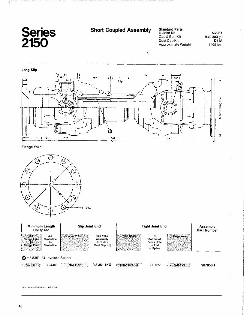
Series 2150
Long Slip
Flange Yoke
Short Coupled Assembly Standard Parts U-Joint Kit Cap & Bolt Kit Dust Cap Kit Approximate Weight
Minimum Length Collapsed
Slip Joint End Tight Joint End
· A·1 A-2 Flange Fa� Centerline to to Flange Faee Centerline
f"lange Yoke
C)= 5.835"- 34 I nvolute Spl ine
56.940" 33.440" 9·2·129
(1) Includes 9-70-59 and 16-73-156
48
Slip Yoke Assembly (Includes
Dust Cap Kit)
9-3·351·1 KX 9·82481·1X
N Bottom of
Cross Hole to End
of Spline
27. 125" 9-c2·129
5·298X 9-70·38X (1)
D11A 1465 1 bs.
1 cti i:S Ol c
-r--+HH+--#- � g ,..:
J
Assembly Part Number
907056·1
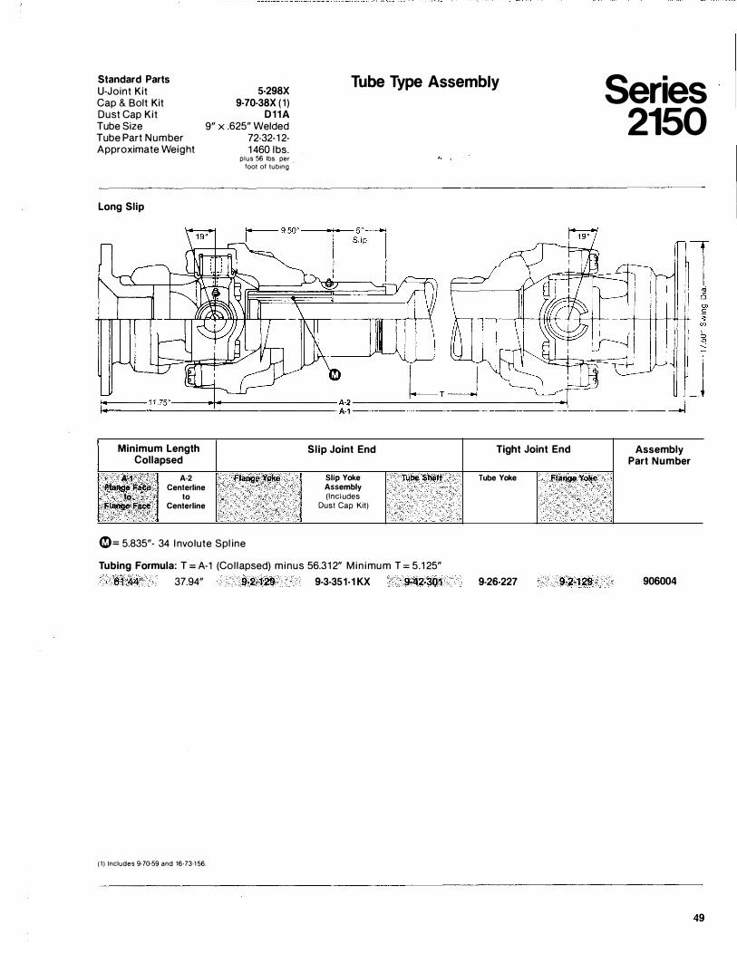
Standard Parts U-Joint Kit 5-298X
9-70-38X (1 ) D11A
9" x .625" Welded 72-32-1 2-1460 lbs.
Tube Type Assembly Cap & Bolt Kit Dust Cap Kit Tube Size Tube Part Number Approximate Weight
Long Slip
Minimum Length Collapsed
A-1 A·2 Flange. F�te� Centerline
to- , , . · .. . to Flange face Centerline
.: ;
plus 56 lbs. per toot of tubing
'
Flangt) '(Q���
�= 5.835"- 34 I nvolute Spl ine
Slip Joint End
Slip Yoke T!lbe 5hl:tft Assembly (Includes
Dust Cap Kit)
Tubing Formula: T = A-1 (Col lapsed) minus 56.31 2" Min imum T = 5.1 25" 61.44" 37.94" 9·2-129 9-3-351-1 KX 9·42;301
( 1 ) Includes 9-70·59 and 16·73-1 56.
Tight Joint End
Tube Yoke Flange Yol(e
9-26-227 9·2·129
Series 2150
1
J Assembly
Part Number
906004
49
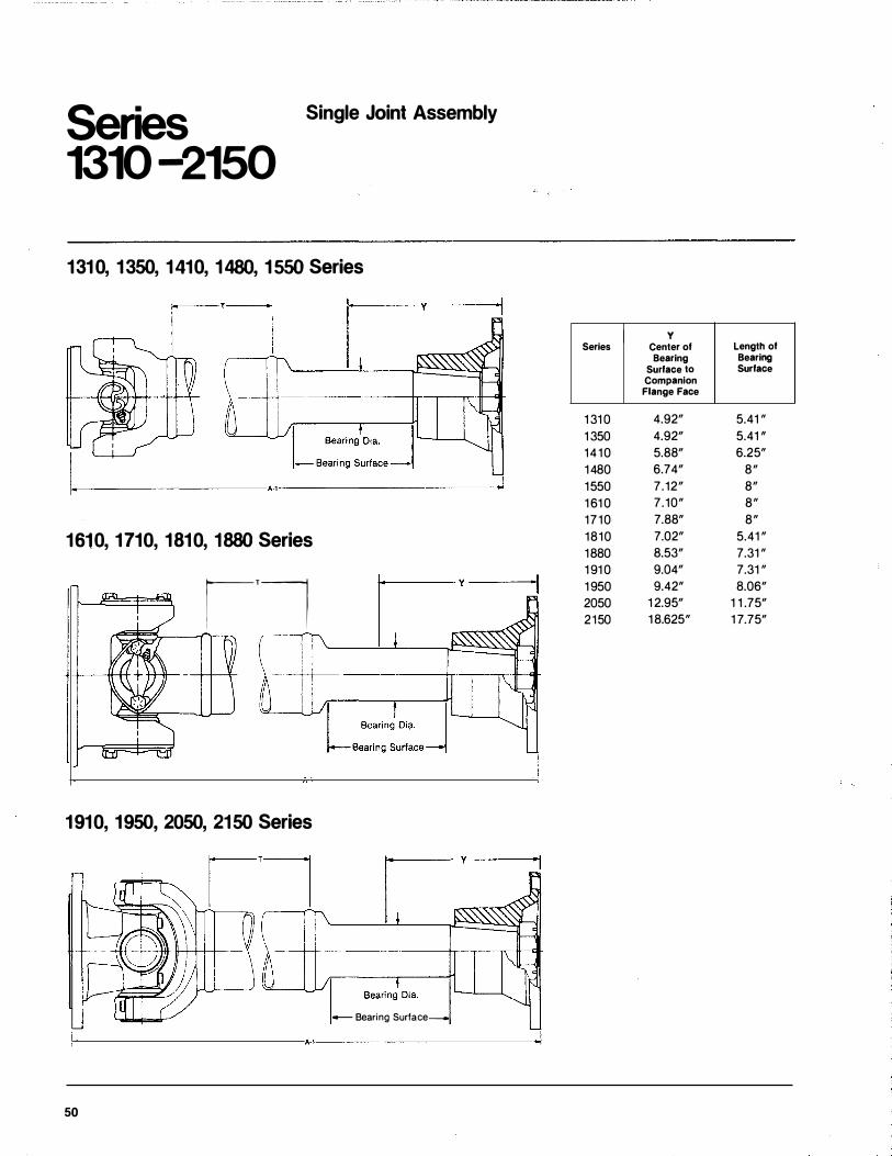
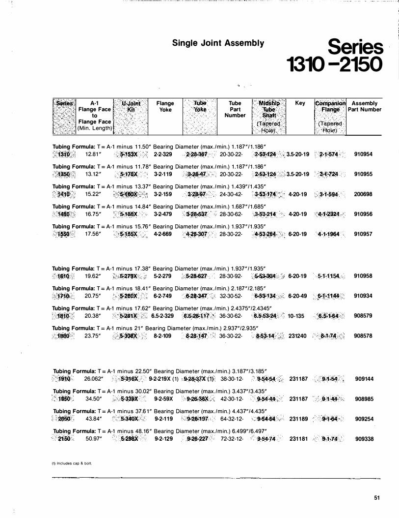
Series 1310 -2150
Single Joint Assembly
1 31 0, 1 350, 1 410, 1 480, 1 550 Series
A·1
1 61 0, 1 710, 1 81 0, 1 880 Series
1'1 r.·
1 91 0, 1 950, 2050, 21 50 Series
- Bearing Surface-
50
Series
1 310 1 350 1410 1480 1550 1 610 1710 1810 1880 1 910 1 950 2050 2150
y Center of Length of Bearing Bearing
Surface to Surface Companion Flange Face
4.92" 5.41 " 4.92" 5.41 , 5.88" 6.25" 6.74" 8" 7.12" 8" 7.10" 8" 7.88" 8" 7.02" 5.41 " 8.53" 7.31 " 9.04" 7.31 " 9.42" 8.06"
1 2.95" 1 1 .75" 1 8.625" 1 7.75"
Single Joint Assembly Series 1310 -2150
Seri�s A·1 U.Joint Flange Tube Tube Midship Key Companion Assembly Flange Face Kit Yoke Yoke Part Tube Flange Part Number
to Number Shaft Flange Face (Tapered {Tapered (Min . Length) Hole) Hole)
Tubing Formula: T = A-1 m inus 1 1 .50" Bearing Diameter (max./min.) 1 . 1 87"/ 1 . 1 86" 1310 1 2.81 " S.153X 2-2-329 2·2&367 20-30-22- 2·53·124 3.5·20·1 9 2·1·574 91 0954
Tubing Formula: T = A-1 minus 1 1 .78" Bearing Diameter (max./min .) 1 .1 87"/1 . 1 86" 1350 1 3. 12" 5·1 78X 3·2·1 19 3·28-47 20·30·22- 2·53·124 3.5·20·1 9 3.1·724 91 0955
Tubing Formula: T = A-1 m inus 1 3.37" Bearing Diameter (max./min .) 1 .439" /1 .435" 1410 1 5.22" 5-160X 3·2·159 3·28·97 24-30-42- 3·53-1 74 4·20·1 9 3·1·594 200698
Tubing Formula: T = A·1 minus 1 4.84" Bearing Diameter (max./m in.) 1 .687"/1 .685" 1480 1 6.75" 5·188X 3·2·479 3·28·537 28-30-62- 3·53·214 4·20·1 9 44·2324 91 0956
Tubing Formula: T = A-1 minus 1 5.76" Bearing Diameter (max./min.) 1 .937"/1 .935" 1550 1 7.56" 5·1 55X 4·2·669 4-28·307 28-30-22- 4·53-264 6·20·19 4·1·1964 910957
Tubing Formula: T = A-1 minus 17 .38" Bearing Diameter (max./min.) 1 .937"/1 .935" 1610 1 9.62" 5·279X 5·2·279 5·28·627 28-30-92- 5·53·304 6·20-1 9 5·1 ·1 1 54 91 0958
Tubing Formula: T = A-1 minus 18.41 " Bearing Diameter (max./min.) 2 . 187" /2. 1 85" 1710 20.75" 5·280X 6-2·749 6·28·347 32-30-52- 6-53-134 6-20-49 6·1·11 44 91 0934
Tubing Formula: T = A-1 minus 1 7.62" Bearing Diameter (max./min.) 2.4375"/2.4345" 1810 20.38" 5·281X 6.5-2·329 6.5·2&117 36-30-62- 6.5·53·24 10 -135 6.5·1·64 908579
Tubing Formula: T = A-1 minus 21 " Bearing Diameter (max./min .) 2.937"/2.935" 1880 23.75" 5·308X 8·2·109 8·28·147 36-30-22- 8·53·14 231240 8·1·74 908578
Tubing Formula: T = A-1 m inus 22.50" Bearing Diameter (max./min .) 3.1 87"/3. 1 85" 1910 26.062" 5·316X 9·2·219X ( 1 ) 9·28·37X (1) 38-30-1 2- 9·54·54 231 1 87 9·1·54 909144
Tubing Formula: T = A-1 minus 30.02" Bearing Diameter (max./min.) 3.437"/3.435" 1950 34.50" 5·339X 9·2·59X 9·26·38X 42-30-1 2- 9·54·44 231 1 87 9·1-44 908985
Tubing Formula: T = A-1 minus 37.6 1 " Bearing Diameter (max./min.) 4.437" /4.435" 2050 43.84" 5·340X 9·2·1 1 9 9-26-197 64-32-1 2- 9·54·64 231 1 89 9·1·64 909254
Tubing Formula: T = A-1 minus 48. 16" Bearing Diameter (max./ m in.) 6.499" /6.497" 2150 50.97" 5·298X 9·2·129 9·26-227 72-32-12- 9·54-74 231 1 81 9·1·74 909338
(1) Includes cap & bolt.
51
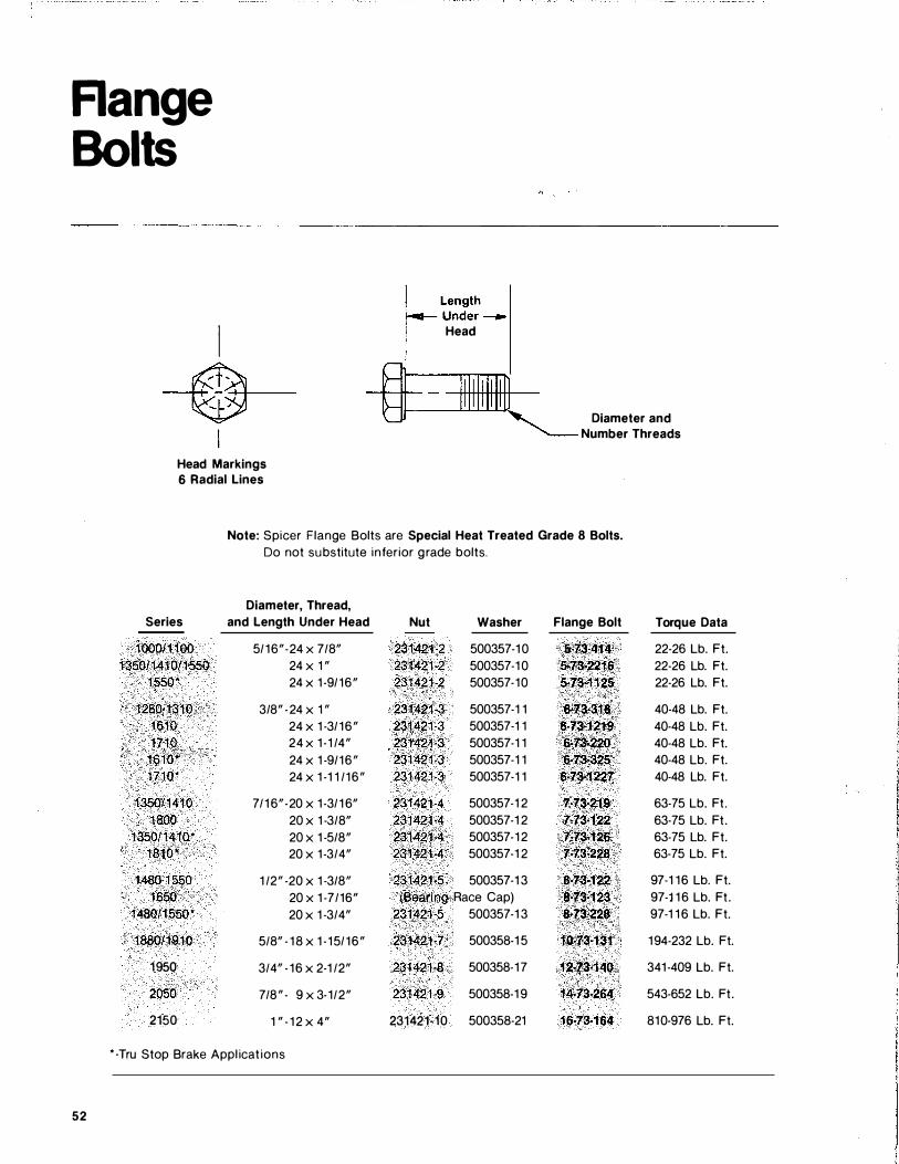
Range Bolts
I ----++�-+-�---�
Head Markings 6 Radial Lines
L��::�-l Head
Rf---------L-1-j III...L.!....l.J<] I jIll � 8 ' Diameter and ""'-- Number Threads
Note: Spicer Flange Bolts are Special Heat Treated Grade 8 Bolts. Do not substitute inferior grade bolts.
Diameter, Thread, Series and Length Under Head Nut Washer Flange Bolt Torque Data
1000/1 100 5/16"-24 X 7/8" 231421�2 500357-1 0 5-73·414 22-26 Lb. Ft. 135011410/1550 24 x 1 " 231421·2 500357-1 0 5�73-2216 22-26 Lb. Ft.
1 550* 24 X 1 -9/16" 231421·2 500357-10 5·73·11 25 22-26 Lb. Ft.
1 280·1310 3/8" -24 x 1 " 231421-3 500357-1 1 6·73-316 40-48 Lb. Ft. 1610 24 X 1 -3/ 16" 231421·3 500357-1 1 6·73·1219 40-48 Lb. Ft. 1710 24 X 1 -1 /4" 231421"3 500357-1 1 6-73;220 40-48 Lb. Ft.
1610* 24 X 1 -9/16" 231421-3 500357-1 1 6·'13·325 40-48 Lb. Ft. 1710* 24 x 1 -1 1 /16" 231421·3 500357-1 1 6·73·1227 40-48 Lb. Ft.
1350/1410 7/1 6"-20 x 1 -3/ 1 6" 231421-4 500357-1 2 7·73·219 63-75 Lb. Ft . 1800 20 x 1 -3/8" 231421-4 500357-1 2 7·73·122 63-75 Lb. Ft.
1 350/1410* 20 x 1 -5/8" 23142H 500357-1 2 7·73·126 63-75 Lb. Ft. 1810* 20 X 1 -3/4" 231421·4 500357-1 2 7·73�228 63-75 Lb. Ft.
1480-1550 1 /2" -20 x 1 -3/8" 231421·5 500357-1 3 8·73·122 97-1 16 Lb. Ft. 1650 20 X 1 -7/16" (Bearing Race Cap) 8·73-123 97-1 1 6 Lb. Ft.
1480/1550* 20 x 1 -3/4" 231421·5 500357-1 3 8·73�228 97-1 1 6 Lb. Ft.
1880/1910 5/8" - 18 x 1 -15/ 16" 231421-7 500358-1 5 10•73·131 194-232 Lb. Ft.
1950 3/4" - 16 x 2-1 /2" 231421·8 500358-17 12·73·140 341 -409 Lb. Ft.
2050 7/8" - 9 x 3-1/2" 231421·9 500358-1 9 14·73·264 543-652 Lb. Ft .
2150 1 " - 1 2 x 4" 231421·10 500358-21 16·73·164 810-976 Lb. Ft.
* -Tru Stop Brake Appl icat ions
52
I I I I I I I I I I
I c
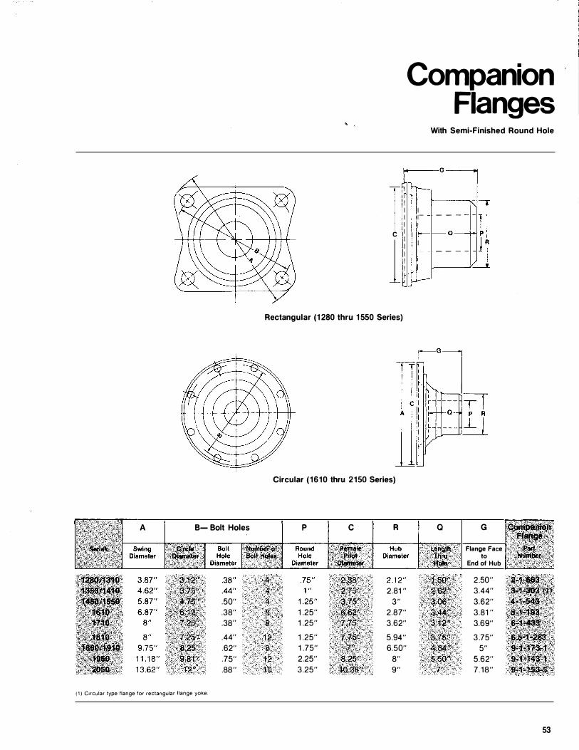
1 Rectangular (1 280 thru 1 550 Series)
Circular (1610 thru 2150 Series)
A B- Bolt Holes p c R
4.�8" 2�:ts" 2.81 "
.50" .�.,75 " 3"
.38" 8 1 .25" ,i?{\} ���f' 2.87"
.38" 8 1 .25" .1;75" 3.62"
.44" 12 1 .25" 1.75" 5.94"
. 62" · a . 1 .75" 7u 6.50"
.75" 12 2.25" a;2oH 8"
.88" 10 3.25" ttl.:18" 9"
( 1 ) C1rcular type flange for rectangular flange yoke.
Companion Flanges
With Semi-Finished Round Hole
�� I 1-I
I 1-I J .....-
- - - - -a --- - - -
-
a
3:75'� 4i!34" 5.50"
7''
G
Flange Face to
End of Hub
2.50" 3.44" 3.62" 3.81 " 3.69"
3 .75" 5"
5.62" 7 . 18"
53
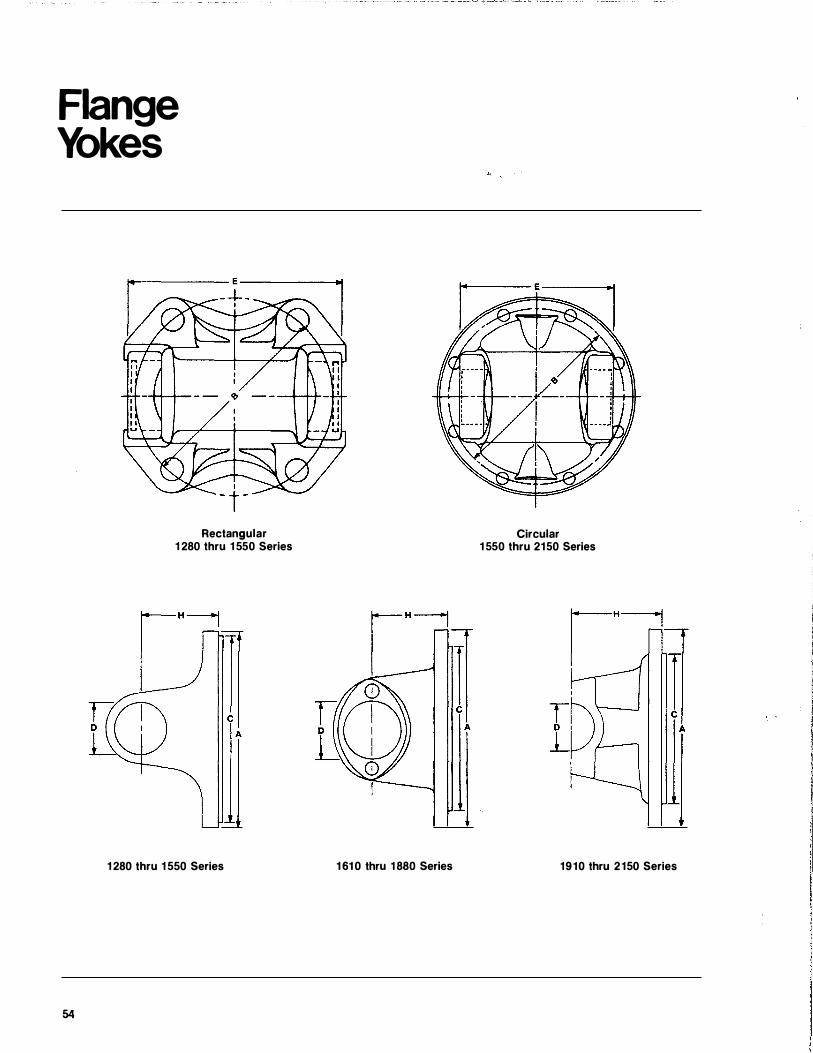
Flange Yokes
54
Rectangular 1 280 thru 1 550 Series
1 280 thru 1 550 Series
Circular 1 550 thru 2150 Series
1 61 0 thru 1 880 Series 1910 thru 2150 Series
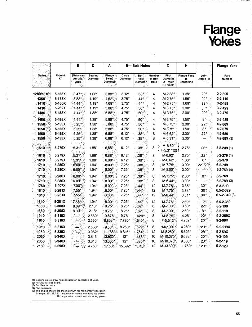
E D A B- Bolt Holes c H
Series
1280/1310 1350 1 41 0 1410 1480
1480 1 550 1 550 1 550 1550
1610
1 61 0 1 61 0 1 71 0 1 71 0
1710 1710 1 760 1810 1810
1810 1880 1880 1910 1 910
1910 1950 2050 2050 21 50
U-Joint Kit
5·153X 5-1 78X 5·1 60X 5·262X 5·188X
5·188X 5·155X 5·155X 5·155X 5·155X
5·279X
5·279X 5·279X 5·280X 5·280X
5·280X 5·280X 5·407X 5·281X 5·281X
5·281X 5·308X 5·308X
5·316X 5·316X
5·316X 5·339X 5·340X 5·340X 5·298X
Distance Across
lugs
3.47" 3.88" 4.44" 4.44" 4.44"
4.44" 5.25" 5.25" 5.25" 5.25"
5.31 "
5.31" 5.31 " 6.09" 6.09" 6.09" 6.0911
7:00" 7.5511
7.5511
7.5511
8.091'
8.09"
Bearing Diameter
1 .06" 1 . 1 9" 1 . 1 9" 1 . 1911
1 .38"
1 .38" 1 .38" 1 .38" 1 .38" 1 .38"
1 .8811
1 .88" 1 .8811 1 .9411 1 .94"
1 .9411 1 .9411 1 .9411
1 .9411
1 .94"
1 .9411
2.18" 2.18" 2.560" 2.56011
2.56011 3.06211 3.81311
3.81311
4.75011
( 1 ) Bearing plate screw holes located on centerline of yoke. (2) For AC tru-stop brake. (3) For Bendix brake. (4) Nut clearance.
Flange Swing
Diameter
3.881'
4.62" 4.691'
5.88" 5.88"
5.88" 5.88" 5.881'
6.88" 6.88"
6.88"
6.88" 6.88" 8.001'
8.0011
8.00'1
8.00" 8 .0011
8.00" 8.0011
8.00" 9.75" 9.75''
10.875" 8.858"
Circle Diameter
3.1211 3.7511
3.7511 4.7511 4.7511
4.7511
4.7511
4.7511
6.1211 6.1211
6.1211
6.1211 6. 1 211 7.2511 7.2511
7.2511 7.2511 7.2511 7.2511 7.2511
7.2511 8.2511 8.2511 9.75" 7.72011
Bolt Hole
Diameter
.38"
.44"
.4411
.50"
.50"
.50"
.50"
.50"
.3811
.38"
.38"
.38"
.381'
.38"
.3811
.38"
.38"
.44"
.44/'
.44"
.44"
.62"
.62" .629" .640"
9.50" 8.25011 .629/f 1 1 .1a8" 9.81511 .754" 13.630" 1211 .a85" 13.630" 1 211 .8a5" 1 7.50" 15.69211 1 .0101'
(5} The angles shown are the maximum for momentary operation. Example: 22°/29,0 22° angle when mated with long lug yokes,
29° angle when mated with short lug yokes.
Number Pilot Flange Face of Bolt
Hole
4 4 4 4 4
4 4 4 8 8
Diameter M-Male F·Female
M-2.3811 M·2.7511 M-2.75" M-3.7511 M·3.75"
M-3.7511 M-3.75" M-3.7511 M-6.6211 M-5.31 "
8 f M-6.62" l � F-5.31 "(2) f
8 M-6.62'1 8 M-6.6211 8 M-7.75" 8 M-8.00"
8 8 1 2 1 2 1 2
1 2 8 8 8 8
M-7.75" M-6.44" M-7.75" M-7.75" M-6.44" M-7.75" M-7.00" M-7.00" M-8.75" F-5.512"
to Centerline
1 .3811
1 .5611 1 .6911 2.0011
2.00"
1 .5011 2.0011 1 .50" 2.00" 2.00"
2.75"
2.7511 1 .8811 3.0011 3.0011
2.0011 3.0011 3.38" 3.3811 3.3 1 11
2.5911 3.5011 2.5011
4.25" 4.25211
8 12 1 0 1 0 1 2
M-7.00" 4.25011 M-8.250" 8.62511 M-10.375" 6.68811
M-10.375'1 9.50011
M-13.69011 1 1 .75011
Flange Yokes
Joint Angle (5)
a · 22 ° a · 22 °
22 ° a ·
22 °/29 °
a ·
3o•
30 ° 30 °
Flange Yoke
Part Number
2·2·329 3·2·1 19 3·2·159 3·2·429 3-2-479
3·2·489 4·2·669 4·2·679 4·2·689 4·2·699 (3)
5·2·249 (1 )
5·2·279 (1 ) 5·2·379 6·2·749 6·2·759 (4)
6·2·769 6-2-789 (3) 6.3·2·19 6.5·2·329 6.5·2·349 (3)
6.5·2·359 8·2·109 8·2·1 19 9·2·269X 9·2·99X
9·2·219X 9·2·59X 9·2·109 9·2·1 19 9·2·129
55
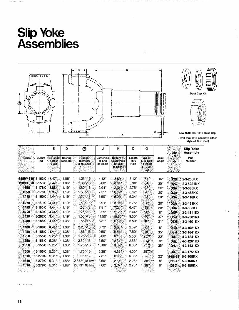
Slip Yoke Assemblies
E D �
series U-Joint Distance Bearing Spline Kit Across Diameter Diameter
Lugs & Number
1280/1310 5-1 53X 3.47" 1 .06" 1 .25"·16 1280/1310 5·1 53X 3.47" 1 .06" 1 .38"·16
1350 5-1 78X 3.88" 1 . 1 9" 1 .50"·16 1 350 5-1 78X 3.88" 1 . 1 9" 1 .50"-16 1410 5-1 60X 4.44" 1 . 1 9" 1 .50"-16
1410 5-160X 4.44" 1 . 1 9" 1 .50"·16 .1410 5-160X 4.44" 1 . 1 9" 1 .50"-16 1410 5-1 60X 4.44" 1 . 19" 1 .75''·16 1410 5-262X 4.44" 1 . 1 9" 1 .56"-16 1480 5·1 88X 4.44" 1 .3S" 1 .56"·16
1480 5·1 88X 4.44" 1 .3S" 2.25"·1.0 1480 5-1 88X 4.44" 1 .3S" 1 .56"-16 1 550 5-1 55X 5.25" 1 .3S" 1 .75"·16 1550 5-1 55X 5.25" 1 .3S" 2.50"·16 1 550 5·1 55X 5.25" 1 .3S" 1 .75"- 16
1550 5·1 55X 5.25" 1 .3S" 1 .75"-16 1 610 5-279X 5.31 " 1 .SS" 2"· 16 1610 5-279X 5.31" 1 .S8" 2.673"-18 l nv. 1610 5-279X 5.31 " 1 .SS" 2.673"-1S lnv.
56
�+------- a ---------1
J K a 0
Centerline Bottom of Length End of Joint to End Cross Hole Thru Slip Yoke Angle
of Spline to End Hole to Inside of Spline of Oust
Cap
4.12" 3.59" 3.1 2" .34" 16° 6.SS" 6.34" 5.3S" .34" 30 ° 3.94" 3.34'' 2.75" .28" 20° 7.31 " 6.72" 6. 12" .28" 20° 6.50" 5.90" 5.34" .28" 20°
3.91" 3.3 1 " 2.75" .28" 20° 7.S1 " 7.21" 6.47" .28" 28° 3.25" 2.65" 2.44" .28" s o 1 1 .50" 10.90" 9.50" .40" 37° 6.S1 " 6,12" 5.50" .40" 21 °
3.72" 3.03" 2.59" .25" so 9.50" 8.81" 7.50" .40" 35° 6.SS" 6.18" 5.50" .257" 22° 3.50" 2.81" 2.56" .413" s o 10.06" 9.37" S.OO" .257» 35°
5.3S" 4.69" 4.00" .257" 7.S1 " 6.88" 6.3S" 22° 3.50" 2.57" 2.25" .38" so 4.00" 3.07" 2.75" .38" so
D\ISt Cap
or Kit
028
D2C D3A D3A 03A 03A D3A D4F 03H D3H 030 03H 04J 04L 04J D4J
Dust Cap Kit
new 1610 thru 1 810 Dust Cap
(1610 thru 1 81 0 can have either style of Dust Cap)
Slip Yoke Assembly
Part Number
2·3·258KX 2·3·5221 KX 3·3·388KX 3·3·488KX 3·3·11 8KX
3·3·468KX 3·3·508KX 3·3·151 1 KX 3·3·2381 KX 3·3·1601 KX
3·3·1621 KX 3·3·1 641 KX 4·3·1 241 KX 4·3·1261 KX 4-3·1 431 KX
4-3-1 751 KX
5·86·68 5·3·1 08KX
05C 5-3-168KX
05C 5·3·18:8KX
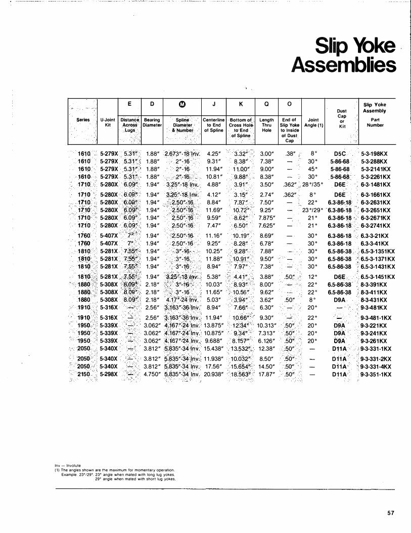
E D �
Series U-Joint Distance Bearing Spline Kit Across Diameter Diameter
Lugs & Number
1 61 0 5-279X 5.31" 1 .88" 2.673"·18 lhV. 1 61 0 5·279X 5.31 " 1 .88" 2"·16 1610 5·279X 5.31 " 1 .88" 2"·16 1 61 0 5·279X 5.31 " 1 .88" 2"·16 1 71 0 5·280X 6.09" 1 .94" 3.25"·18 lnv.
1 71 0 5·280X 6.09" 1 .94" 3:25"·18 l nv. 171 0 5·280X 6.09" 1 .94" 2.50"·16 1710 5·280X 6.09" 1 .94" 2.50"·16 1 71 0 5·280X 6.09" 1 .94" 2.50"·16 1 71 0 5·280X 6.09" 1 .94" 2.50"·16
1760 5·407X 7" 1 .94" 2.50"·16 1 760 5·407X 7" 1 .94" 2.50"·16 1 81 0 5·281 X 7.55" 1 .94" 3"·16 1 81 0 5·281 X 7.55" 1 .94" 3"·16 1810 5·281X 7;55" 1 .94" 3"·16
1810 5·281X 7.55'1 1 .94" 3.25"·18 .lnv. 1 880 5·308X 8;098 2 . 18" 3"·16 1 880 5·308X 8.09" 2 .18" 3"·16 1 880 5·308X 8.09" 2.18" 4.17"-24 lnv. 1910 5·316X 2.56" 3.163"·36 1nv.
1910 5·316X 2.56" 3.163"·36 lnv. 1 950 5·339X 3.062" 4.167"·24 1nv. 1 950 5·339X 3.062" 4.167"·24 1nv. 1950 5·339X 3.062" 4.167"·24 lnv. 2050 5-340X 3.81 2" 5.835"·34 lnv.
2050 5·340X 3.812" 5.835"·34 lnv. 2050 5·340X 3.812" 5.835"·34 lnv. 2150 5·298X 4.750" 5.835"·34 lnv.
!nv - Involute (1) The angles shown are tl-te maximum for momentary operation
Example: 23°/29°, 23° angle when mated with long lug yokes. 29° angle when mated with short lug yokes
J K
Centerline Bottom of to End Cross Hole
of Spline to End of Spline
4.25" 3.32" 9.31 " 8.38" 1 1 .94" 1 1 .00" 10.81 " 9.88" 4.88" 3.91 "
4.1 2" 3 . 15" 8.84" 7.87" 1 1 .69" 10.72" 9.59" 8.62" 7.47" 6.50"
1 1 . 16" 10.19" 9.25" 8.28" 1 0.25" 9.28" 1 1 .88" 10.91 " 8.94" 7.97"
5.38" 4.41" 1 0.03" 8.93" 1 1 .65" 1 0.56" 5.03" 3.94" 8.94" 7.66"
1 1 .94" 1 0.66" 1 3.875" 1 2.34" 10.875" 9.34" 9.688" 8.157" 1 5.438" 1 3.532"
1 1 .938" 1 0.032" 1 7.56" 1 5.654" 20.938" 1 8.563"
a
Length Thru Hole
3.00" 7.38" 9.00" 8.38" 3.50"
2.74" 7.50" 9.25" 7.875" 7.625"
8.69" 6.78" 7.88" 9.50" 7.38"
3.88" 8.00" 9.62" 3.62" 6.30"
9.30" 10.313" 7.313" 6 . 126" 1 2.38"
8.50" 14.50" 17.87"
Slip Yoke Assemblies
0 Slip Yoke
Oust Assembly
End of Joint Cap
Part or Slip Yoke Angle (1) Kit Number to Inside of Dust
Cap
.38" 8 0 D5C 5·3·1 98KX 30 ° 5·86·68 5·3·288KX 45 ° 5·86·68 5·3·2141KX 30 ° 5·86·68 5·3·2261 KX
.362" 28 °/35 ° 06E 6·3-1481 KX
.362" 8 0 D6E 6·3·1661 KX 22 ° 6.3·86·18 6·3·2631 KX
23 °/29 ° 6.3·86·18 6·3·2651 KX 21 ° 6.3·86·18 6·3·2671KX 21 ° 6.3·86·18 6·3-2741 KX
30 ° 6.3·86·18 6.3·3·21 KX 30 ° 6.3·86·1 8 6.3·3·41 KX 30 ° 6.5·86·38 6.5·3·1 351 KX 30 ° 6.5·86·38 6.5·3·1 371 KX 30 ° 6.5·86·38 6.5·3·1 431 KX
.50" 1 2 ° D6E 6.5·3·1451 KX 22 ° 6.5·86·38 8·3·391 KX 22 0 6.5·86·38 8·3·41 1 KX
.50" 8 0 D9A 8·3·431 KX 20 ° 9·3·481KX
22 ° 9·3-481 ·1 KX .50" 20 ° D9A 9·3·221 KX .50" 20 ° D9A 9·3·241 KX .50" 20 ° D9A 9·3·261 KX .50" D1 1 A 9·3·331 ·1 KX
.50" D 1 1 A 9·3·331 ·2KX .50" D1 1 A 9·3·331 ·4KX .50" D11A 9·3·351 ·1 KX
57
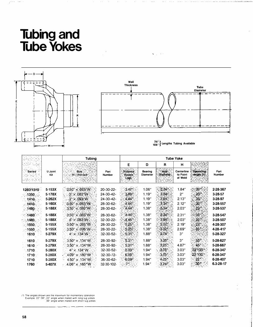
Tubing and Tube Yokes
Tubing
Series U·Joint Si%e · Kit W-Wefded
1280/1310 5-1 53X 2.50" x .083"W 1 350 5·1 78X .3" x .083"W 1410 5·262X 3" x .083'W
1410 5·1 60X 3.50" x .083"W 1 480 5·1 88X 3.50" X .083"W
1 480 5·1 88X 3.50" X .083"W 1 480 5-1 88X 4" x .083"W 1 550 5·1 55X 3.50" X .095"W 1 550 5·1 55X 3.50" x .095"W 1 610 5·279X 4" x . 134"W
1 61 0 5-279X 3.50" X . 134"W 1610 5·279X 3.50" X . 134"W 1 710 5·280X 4" X . 134"W 1710 5·280X 4.09" X . 180"W 1710 5-280X 4.50" X . 134"W 1 760 5·407X 4.06" x .1 65"W
( 1) The angles shown are the max1mum for momentary operat1on Example 22" i30" 22o angle when mated w1th long lug yokes
30" angle when mated With short lug yokes
58
Wall Thickness
- - - - - - -r - - - - - - -
E Part Distance
Number Acros.$ Lugs
20-30-22- 3AT' 24-30-42- 3.88'' 24-30-42- 4.44" 28-30-62- 4.44" 28-30-62- 4.44" 28-30-62- 4.44" 32-30-22- 4.44" 28-30-22- 5,25" 28-30-22- 5.25" 32-30-52- 5.31 "
28-30-92- 5.31 " 28-30-92- 5.31 ''
32-30-52- 6.09" 32-30-72- 6.09" 36-30-62- 6.09" 32·30-102· 7"
D Bearing
74 " l 108 .. f Lengths Tubing Available
Tube Yoke
R H 1 , ; flub Centerline �.JeiauP9-
Diameter Oiame�e� to Point ""''•t1l of Weld !'•,· i!i •
1 .06" 2.34'1 1 .84" · · Goo 1 . 1 9" 2.84?, 2" 20" 1 . 19" 2.84': 2.1 3" 1 . 19" 3.�(1 2.12" 1 .38" 3:34� 2.03"
1 .38" ·3.34": 2.31 " 1 .38" 3J�4�� - 2.03" ··· ·· .. 22" 1 .38" 3,32". 2.19" . 22" 1 .38" 3.32" 2.69" .-35" 1 .88" 3.74" 3"
1 .88" 3.25" 3" 35° 1 .88" 3.25" 4.87" 45° 1 .94" 3.75" 3.03" 22 "130 °
1 .94" 3.75" 3.03" 22 "/30 °
1 .94" 4.25" 3.03" 22 ° 1 .94" 3.74" 3.03" 3o •
•••
Part Number
2·28-367 3-28-57 3·28-97 3·28-557 3·28-537
3·28-547 3·28-507 4·28-307 4-28-417 5·28-327
5·28-627 5·28-667 6·28-347 6·28-347 6·28-407 6.3·28·17
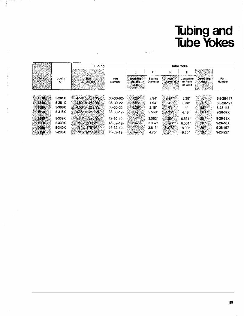
5·281 X 4,1$0" � .134�\tll 5·281X ; 4;50:" .x .2S��·· 5·308X 45Q" · 259l'W ?< ' • · ., X �· • ;��� 5·316X 4;75 X -2�"�' • . . 5·339X
'. s:is" x .$:7'5"� 5·339X ;�· ····.��·�···:�����\· 5·340X 5·298X 9"x .625"W•;
Part Number
36-30-62-36-30-22-36-30-22-38-30-12-
42-30-1 2-48-32-1 2-64-32-1 2-72-32-1 2-
E D
'DI$timce'' Bearing A¢1qS$ Diameter
; ,.��gS. 1 .94" 1 .94" 2 .18" 2.560"
3.062" 3.062" 3.813" 4.75"
Tubing and Tube Yokes
Tube Yoke
R
4" 4''
.4.25."
4.50" · 5;146" ·' · ·?:375'1
8"
H Centerline Oper•tlng
to Point A�tgl• of Weld
3.38" 3Q" 3.38" 30<>
4" ��� 4 . 19" 20 �
6.531 " 20"
6.531 " 2Q" 8.09" 2o•s · 9.25" 19 "
Part Number
6.5·28·1 1 7 6.5·28·127 8-28·147 9-28·37X
9-26·38X 9·26·18X 9-26·197 9-26·227
59
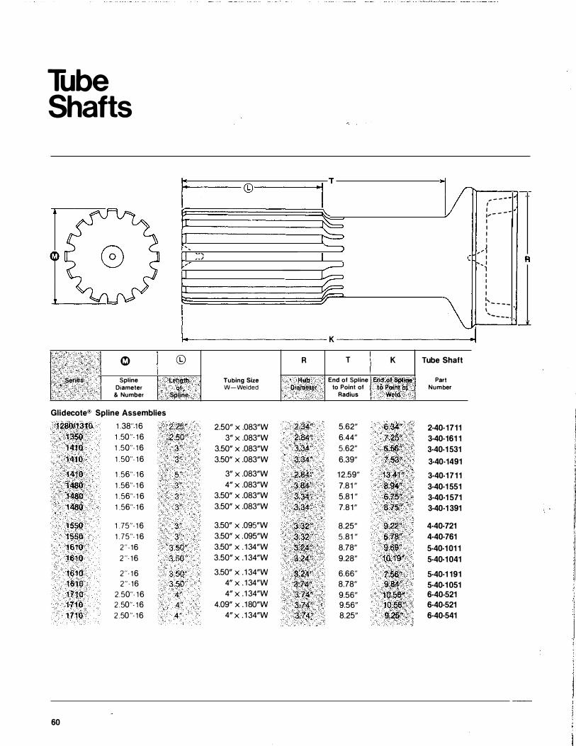
Tube Shafts
I � ! Series Spline
Diameter & Number
1 ' ' I
/
I
I ©
· t.engJh: ol
Spline
Glidecote® Spline Assemblies
128011310 1 .38"- 1 6 2.25"-1 350 1 .50"- 1 6 2.50" 1 410 1 .50"- 1 6 3" 1 41 0 1 . 50"- 1 6 3"
1410 1 .56"- 1 6 5 " 1480 1 .56"- 1 6 3"
1480 1 . 56"- 1 6 3" 1 480 1 .56"- 1 6 3"
1 550 1 .75"- 1 6 3"
1550 1 . 75"- 1 6 3'' 1 610 2" - 16 3.50" 1610 2"· 16 3.50"
1 61 0 2"· 1 6 3.50" 1 61 0 2" · 16 3 .50" 1710 2.50"- 1 6 4" 1710 2 .50"- 1 6 4" 1710 2 .50"- 16 4 "
60
L
.,
.J
Tubing Size W-Welded
2.50" X .083"W 3" x .083"W
3.50" X .083"W 3.50" X .083"W
3" x .083"W 4" x .083"W
3.50" X .083"W 3.50" X .083"W
3.50" X .095"W 3.50" X .095"W 3.50" X . 134"W 3.50" X . 1 34"W
3.50" X . 1 34"W 4" x . 134"W 4" x .1 34"W
4.09" X . 180"W 4" x . 1 34"W
..
v ·-, - - - ,
I
: .. - - -:--- I
I I
I I
"--) J ,' I J ( I R � ', I 1 l I I
� I I
\ I, I - - - -I ..... _ _ __
, _
K
R T K Tube Shaft
HIIQ End of Spline End of S!)Ji� Part Diameter to Point of to Point of Number
Radius Weld
2.34" 5.62" 6.34" 2·40·1711 2.iW' 6.44" 7.25" 3·40·161 1 3.34" 5.62" 6.56." 3·40-1 531 3.34" 6.39" 7.53 " 3·40-1491
2.84" 12.59" 1 3.41" 3·40-1711 3.84" 7.81 " (1:94." 3·40·1 551 3;34" 5.81 " 6.75'f 3·40·1 571 3.34" 7.81" 8.75" 3·40·1 391
3.32" 8.25" 9.22" 4·40·721
3-.32" 5.81 " 6:78" 4·40-761
3;24" 8.78" 9.69" 5·40·1 01 1 3;24'! 9.28" 10.19" 5-40·1 041
3.24" 6.66" 7.S6'' 5·40·1 191 3.74" 8.78" 9.841' 5·40·1 051 3.74" 9.56" 10.56:'' 6·40-521 3;.74" 9.56" 10.56" 6·40·521 3.74" 8.25" 9.25" 6·40·541
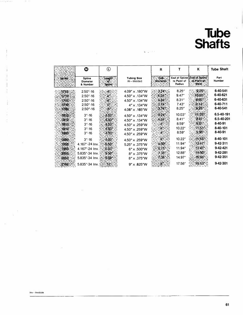
0 C0 R
Spline Tubing Size Diameter W-Welded
& Number
2.50"· 16 4.09" X . 180"W 2.50"-16 4.50" X . 134"W 2.50"·16 4.50" X . 1 34"W 2.50"-16 4" x . 134"W 2.50"- 16 4.06" X . 165"W
3"-16 4.50" X . 134"W 3"-16 4.50" X . 134"W 3"-16 4.50" X .259"W 3"-16 4.50" X .259"W 3"-16 4.50" X .259"W
3"-16 4.50" X .259"W 4.167"-24 lnv. 5.25" X .375"W 4.1 67"-24 lnv. 6" x .500"W 5.835"-34 lnv. 8" x .375"W 5.835"-34 lnv. 8" x .375"W
5.835"-34 lnv. 9" x .625"W
lnv - Involute
T
9.47" 8.31 " 7.43" 8.25"
10.03" 8.41 " 8.59" 10.22" 8.59"
10.22" 1 1 .94" 1 1 .94" 12.88" 14.97"
17.56"
Tube Shafts
K Tube Shaft
Part Number
6-40·541 6-40-621 6-40-631 6-40·71 1 6-40·541 't1.2'6'�\ 6.5·40·191
· .. i.4r<ic; ', >>"·· ' ' ' \ 6.5-40·201 '":91 "• '� 8-40-91 11;s�· 8-40-101
9�9:'0'< 8-40-91
�'t�l�i3'j'i 8-40·101
taA:r" 9-42-31 1 ··��:41"/' 9-42·421 f:.lf.50" 9-42·281
-�16,60" 9·42·351 . , :c,i.�:sa:, 7 9·42·301
61
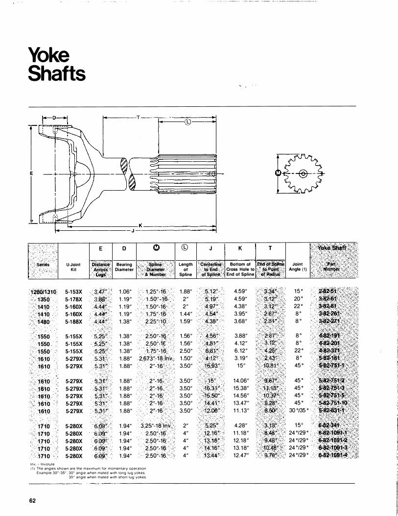
Yoke Shafts
I
I E - +
I I
Series U-Joint Kit
128011310 5·1 53X
1350 5-1 78X 1410 5·1 60X 1410 5-1 60X
1480 5·1 88X
1550 5-1 55X
1 550 5·1 55X
1550 5·1 55X
1610 5·279X
1610 5·279X
1 610 5-279X
1610 5-279X
1610 5·279X
1 610 5-279X
161 0 5-279X
1710 5-280X 1710 5-280X 1 710 5-280X 1 710 5·280X 1 71 0 5-280X
l n v Involute
E
Distance Across
Lugs
3.47" 3.88''
4.44" 4.44"
4.44"
5.25" 5.25"
5.25"
5.31 "
5.31"
5.31 "
5.31 " 5.31 "
5.31 " 5.31"
6 .09" 6.09" 6.09" 6.09" 6.09"
K J
D �
Bearing Spline Diameter .Diameter
& Number
1 .06" 1 .25"-16 1 . 19" 1 .50"-16 1 . 1 9" 1 .50"-16 1 . 19" 1 .75"-16 1 .38" 2.25"-10
1 .38" 2.50"-16 1 .38" 2.50"-1€ 1 .38" 1 .75"-16 1 .88" 2.673"·18 lnv. 1 .88" 2"-16
1 .88" 2"·16 1 .88" 2"-16
1 .88" 2"·16 1 .88" 2"·16 1 .88" 2"-16
1 .94" 3.25"- 18 lnv. 1 .94" 2.50"-16 1 .94" 2.50"-16 1 .94" 2.50"-16 1 .94" 2.50"-16
( 1 ) The angles shown are the max1mum for momentary operat1on
Example 30" /35"' 30" angle when mated w1th long lug yokes, 35" angle when mated w1th short lug yokes
62
©
Length of
Spline
1 .88" 2" 2"
1 .44" 1 .59"
1 .56" 1 .56" 2.50" 1 .50" 3.50"
3.50" 3.50" 3.50" 3.50" 3.50"
2" 4" 4" 4" 4"
ii-=I
J K T Vo�eShltft
Centerline Bottom of End ot spnne Joint Part to End Cross Hole to to Point .. · Angle (1) Nu�ber
of Spline End of Spline of Radius
5.12" 4.59" 3.34" 1 5 ° 2..S2·51 5.19" 4.59" 3.12" 20 ° 3·82,61
4.97" 4.38" 3.12" 22 ° 3-82•81 4.54" 3.95" 2.67" 8. 3-8�261 4.38" 3.68" 2�81 " a · a.sa-271
4.56" 3.88" 2.87" 8 . +82•191 4.81 " 4.12" 3.12" 8. 4�82�201 6.81 " 6.12" 4.25" 22 ° ·�<3'71. 4.12" 3.19" 2.43" 8 . 5·82·161 15.93" 1 5" 10.81" 45 ° 5-82·751-1
1 5" 14.06" 9.87" 45 ° 5·J2·151·2 16.31 " 15.38" 1 1 :t8" 45 ° 5:82•7$1-3 15.50" 14.56" 10.37" 45 ° 5..S2.751•5 14.41" 13.47" 9 .. 28" 45 ° S.82�JS1·1b 12.06" 1 1 . 1 3" 8.50" 30 •t35 ° 5.82·831�1
5.25" 4.28" 3.13" 1 5° 6·82·34.1 12.16" 1 1 . 18" 8.48" 24 °/29 ° 6·8�109'*"1. 13.16" 12. 18" 9.48" 24 °/29 ° 6·824091•2 14. 16" 13. 1 8" 1 0.48" 24 °129 ° 6·82·109'M\ 13.44" 12.4 7" 9.76" 24 °/29 ° 6..S2·1091.,4
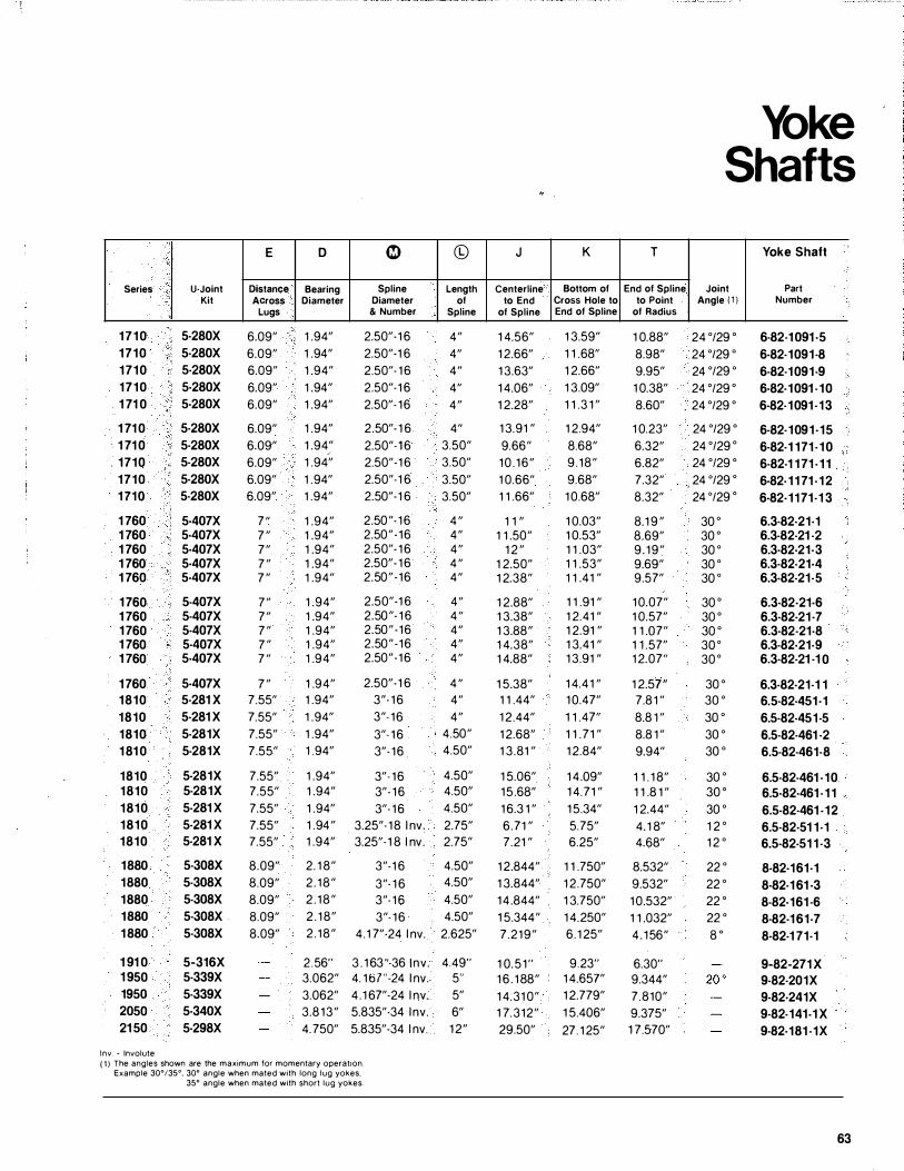
Series
1710 1710 1710 1710 1 71 0
1 71 0 1 71 0 1710 1710 1 710
1 760 1 760 1 760 1 760 1 760
1 760 1 760 1 760 1 760 1 760
1 760 1810 1810 1810 1 81 0
1810 1810 1810 1810 1810
1880 1880 1880 1880 1 880
1 91 0 1 950 1950 2050 21 50
lnv. - Involute
U-Joint Kit
5·280X 5·280X 5·280X 5·280X 5·280X
5·280X 5·280X 5-280X 5·280X 5·280X
5·407X 5·407X 5·407X 5·407X 5·407X
5-407X 5-407X 5·407X 5·407X 5·407X
5·407X 5·281 X 5·281 X 5·281X 5·281X
5·281X 5·281X 5·281 X 5·281 X 5·281 X
5·308X 5·308X 5-308X 5·308X 5·308X
5-316X 5·339X 5·339X 5·340X 5·298X
E
Distance Across
Lugs
6.09"
6.09"
6.09"
6.09"
6.09"
6.09"
6.09"
6.09"
6.09"
6.09"
7 "
7 "
7 "
7 "
7 "
7 "
7 "
7 "
7 "
7 "
7 "
7.55"
7.55"
7.55"
7.55"
7.55"
7.55"
7.55"
7.55"
7.55"
8.09"
8.09"
8.09"
8.09"
8.09"
D
Bearing Diameter
1 .94"
1 .94"
1 .94"
1 .94"
1 .94"
1 .94"
1 .94" .· 1 .94"
1 .94"
1 .94"
1 .94"
1 .94"
1 .94"
1 .94"
1 .94"
1 .94"
1 .94"
1 .94"
1 .94"
1 .94"
1 .94"
1 .94"
1 .94"
1 .94"
1 .94"
1 .94"
1 .94"
1 .94"
1 .94 "
1 .94"
2. 1 8"
2 . 1 8 "
2 . 1 8 "
2 . 1 8"
2 . 1 8 "
� ©
Spline Length Diameter of & Number Spline
2.50"·1 6 4 "
2.50"·1 6 4"
2.50"- 1 6 4 "
2.50"-1 6 4"
2.50"- 1 6 4 "
2.50"· 1 6 4"
2.50"-1 6 3.50"
2.50"-1 6 3.50"
2.50"-1 6 3.50"
2.50"-1 6 3.50"
2.50 "- 1 6 4 "
2.50 " · 1 6 4 "
2.50"- 1 6 4 "
2.50"- 1 6 4 "
2.50 " - 1 6 4 "
2.50"-1 6 4 "
2.50 "- 1 6 4 "
2.50 " - 1 6 4 "
2.50 " - 1 6 4 "
2.50"·1 6 4 "
2.50"-1 6 4 "
3"- 1 6 4 "
3"- 1 6 4 "
3"- 1 6 4.50"
3"- 1 6 4.50"
3"- 1 6 4.50"
3"- 1 6 4.50"
3"- 1 6 4.50"
3.25"- 1 8 l nv. 2.75"
3.25"-1 8 l nv. 2.75"
3"-1 6 4.50"
3"- 1 6 4.50"
3"- 1 6 4.50"
3"- 1 6 4.50"
4.1 7"-24 l nv. 2.625"
2 . 56" 3 . 1 63 "-36 1nv. 4.49"
3.062" 4. 1 6 7 "-24 l nv. 5"
3.062" 4 . 1 67"-24 l nv. 5"
3.8 1 3 " 5.835"-34 l nv. 6"
4. 750" 5.835"-34 l nv. 1 2"
( 1 ) The angles shown are the maximum for momentary operatton. Example 30°/35°, 30° angle when mated with long lug yokes.
35° angle when mated with short lug yokes.
J
Centerline to End
of Spline
1 4.56"
1 2.66"
1 3.63"
1 4.06"
1 2.28"
1 3.91 "
9.66"
1 0 . 1 6 "
1 0.66"
1 1 .66"
1 1 ,
1 1 .50"
1 2 "
1 2.50"
1 2.38"
1 2.88"
1 3.38"
1 3.88"
1 4.38"
1 4.88"
1 5.38"
1 1 .44"
1 2.44"
1 2.68"
1 3.81 "
1 5.06"
1 5 .68"
1 6.3 1 "
6 .71 "
7.21 "
1 2.844"
1 3.844"
1 4 .844"
1 5.344"
7.21 9 "
K
Bottom of Cross Hole to End of Spline
1 3.59"
1 1 .68"
1 2.66"
1 3.09"
1 1 .3 1 "
1 2.94"
8.68"
9 . 1 8 "
9.68"
1 0.68"
1 0.03"
1 0.53"
1 1 .03"
1 1 .53"
1 1 .41 "
1 1 .91 ,
1 2.41 ,
1 2.91 "
1 3.41 ,
1 3.91 ,
1 4.4 1 ,
1 0.47"
1 1 .47"
1 1 .7 1 "
1 2.84"
1 4.09"
1 4.71 "
1 5.34"
5.75"
6.25"
1 1 .750"
1 2.750"
1 3.750"
1 4.250"
6 .1 25"
1 0. 5 1 " 9.23"
1 6 . 1 88" 1 4.657"
1 4.31 0" 1 2.779"
1 7. 3 1 2 " 1 5.406"
T
End of Spline to Point
of Radius
1 0.88"
8.98"
9.95"
1 0.38"
8.60"
1 0.23"
6.32"
6.82"
7.32"
8.32"
8.1 9 "
8.69"
9 . 1 9 "
9.69"
9.57"
1 0.07"
1 0.57"
1 1 .07"
1 1 .57"
1 2.07"
1 2.57"
7.8 1 "
8.8 1 "
8.8 1 "
9.94"
1 1 . 1 8"
1 1 .8 1 "
1 2.44"
4. 1 8"
4.68"
8.532"
9.532"
1 0.532"
1 1 .032"
4 . 1 56"
6.30"
9.344"
7.810"
9.375"
29.50" 27. 1 25" 1 7.570"
Yoke Shafts
Joint Angle (1 )
24 °/29 °
24 °/29 °
24 °/29 °
24 °/29 °
24 °/29 °
24 °/29 °
24 °/29 °
24 °/29 °
24 °/29 °
24 °/29 °
30 °
30 °
30 °
30 °
30 °
30 °
30 °
30 °
30 °
30 °
30 °
30 °
30 °
30 °
30 °
30 °
30 °
30 °
1 2 °
1 2 °
22 °
22 °
22 °
22 °
8 0
Yoke Shaft
Part Number
6·82·1 091 ·5 6·82·1091·8 6·82·1091·9 6·82·1091 -10 6·82·1091 ·13
6·82·1091·15 6·82·1 171 · 1 0 6·82·1 1 71 · 1 1 6·82· 1 1 71 · 1 2 6·82·1171·1 3
6.3·82·21·1 6.3·82·21 ·2 6.3·82·21·3 6.3·82·21·4 6.3·82-21·5
6.3·82·21·6 6.3·82·21·7 6.3·82·21·8 6.3-82·21·9 6.3·82·21 ·1 0
6.3·82·21·1 1 6.5·82-451·1 6.5·82-451-5 6.5-82-461 ·2 6.5·82·461·8
6.5·82-461 -10 6.5·82·461 · 1 1 6.5·82·461 -12 6.5·82·51 1·1 6.5·82-51 1 ·3
8·82·161·1 8·82·1 61 ·3 8-82·161 ·6 8·82-1 61-7 8·82-1 71·1
9-82-271 X 9·82·201X 9-82·241X 9·82-141-1 X 9·82·181 ·1X
63
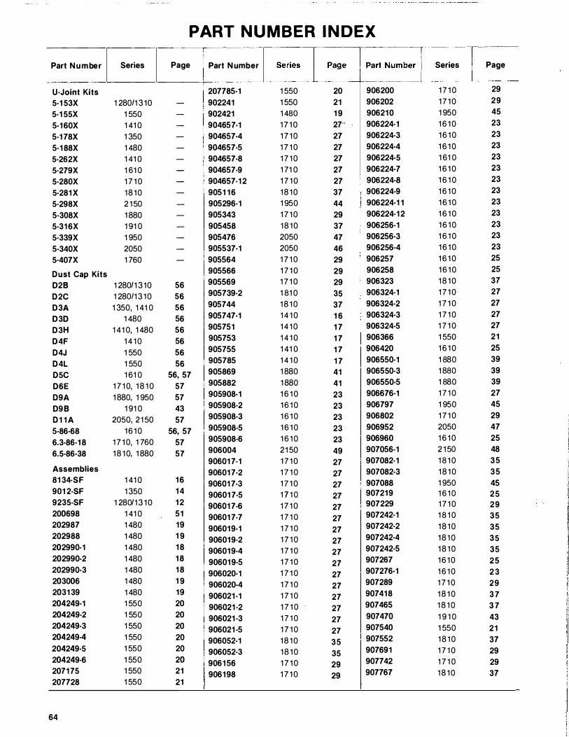
Part Number Series
U·Joint Kits 5·153X 1 280/1 310 5·155X 1 550 5·160X 1 41 0 5·178X 1 350 5·188X 1 480 5·262X 1 41 0 5·279X 1 61 0 5·280X 1 7 1 0 5·281X 18 10 5·298X 2 1 50 5·308X 1 880 5·316X 1 91 0 5·339X 1 950 5·340X 2050 5·407X 1 760
Dust Cap Kits 028 1 280/1 310 D2C 1 280/1 3 10 D3A 1 350, 1 41 0 030 1 480 D3H 1 41 0, 1 480 D4F 1 4 1 0 D4J 1 550 D4L 1 550 D5C 1 61 0 D6E 1 7 1 0, 1 8 1 0 D9A 1 880, 1 950 098 1 91 0 D11A 2050, 21 50 5·86·68 16 10 6.3·86·18 1 7 1 0, 1 760 6.5·86·38 18 10, 1 880
Assemblies 8134·SF 1 41 0 9012·SF 1 350 9235·SF 1 280/1 3 10 200698 1 41 0 202987 1 480 202988 1 480 202990·1 1 480 202990·2 1 480 202990·3 1 480 203006 1 480 203139 1 480 204249·1 1 550 204249·2 1 550 204249·3 1 550 204249·4 1 550 204249·5 1 550 204249·6 1 550 207175 1 550 207728 1 550
64
PART N U M BER I N DEX
Page Part Number
207785·1 - 902241 - 902421 - 904657·1 - 904657·4 - 904657·5 - 904657·8 - 904657·9 - 904657·12 - 905116 - 905296·1 - 905343 - 905458 - 905476 - 905537·1 - 905564
905566
56 905569
56 905739·2
56 905744
56 905747·1
56 905751
56 905753
56 905755
56 905785
56, 57 905869
57 905882
57 905908·1
43 905908·2
57 905908·3
56, 57 905908·5
57 905908·6
57 906004 906017·1 906017·2
16 906017·3 14 906017·5 12 906017·6 51 906017·7 19 906019·1 19 906019·2 18 906019·4 18 906019·5 18 906020·1 19 906020·4 19 906021·1 20 906021·2 20 906021·3 20 906021·5 20 906052·1 20 906052·3 20 906156 21 906198 21
···��: .. � r .. :-Numbe• I . ---·�-- ·-·· · - · -·-�··-··
1 550 20 906200 1 550 21 906202 1 480 19 906210 1 7 10 27'' 906224·1 1 7 10 27 906224·3 1 7 1 0 27 906224·4 1 7 10 27 906224·5 1 71 0 27 906224·7 1 7 1 0 27 I 906224·8 18 10 37 906224·9 1 950 44 906224·11 1 7 10 29 906224·12 18 10 37 906256·1 2050 47 906256·3 2050 46 906256·4 1 7 1 0 29 906257 1 7 1 0 29 906258 1 7 1 0 29 906323 1 81 0 35 906324·1 18 10 37 906324·2 1 4 1 0 16 906324·3 1 4 10 17 906324·5 1 4 1 0 17 906366 1 41 0 17 906420 1 4 1 0 17 906550·1 1 880 41 906550·3 1 880 41 906550·5 1 6 1 0 23 906676·1 1 6 10 23 906797 1 6 10 23 906802 1 6 10 23 906952 1 6 10 23 906960 21 50 49 907056·1 1 7 10 27 907082·1 1 7 1 0 27 907082·3 1 7 1 0 27 907088 1 7 1 0 27 907219
1 7 1 0 27 907229
1 7 1 0 27 907242·1
1 7 1 0 27 907242·2
1 7 1 0 27 907242·4
1 7 1 0 27 907242·5
1 7 1 0 27 907267
1 7 1 0 27 907276·1
1 7 1 0 27 907289
1 7 1 0 27 907418
1 7 1 0 27 907465
1 7 1 0 27 907470
1 7 1 0 27 907540
18 10 35 907552
18 10 35 907691
1 7 1 0 29 907742
1 7 1 0 29 907767
Series I Page
1 7 1 0 29
1 7 10 29 1 950 45 1 6 10 23 1 6 10 23 1 6 10 23 1 61 0 23 1 6 10 23 1 6 1 0 23 1 6 10 23 1 6 10 23 1 6 1 0 23 1 6 10 23 1 6 1 0 23 1 6 10 23 1 6 10 25 1 6 10 25 18 10 37 1 7 1 0 27 1 7 1 0 27 1 7 1 0 27 1 7 1 0 27 1 550 21 1 6 10 25 1 880 39 1 880 39 1 880 39 1 7 1 0 27 1 950 45 1 7 1 0 29 2050 47 1 6 10 25 2 1 50 48 1 8 10 35 18 10 35 1 950 45 1 6 10 25 1 7 10 29 1 8 1 0 35 18 10 35 18 10 35 18 10 35 16 10 25 1 6 10 23 1 7 1 0 29 1 8 1 0 37 1 8 1 0 3 7 1 9 1 0 43 1 550 21 18 10 37 1 7 1 0 29 1 7 1 0 29 18 10 37
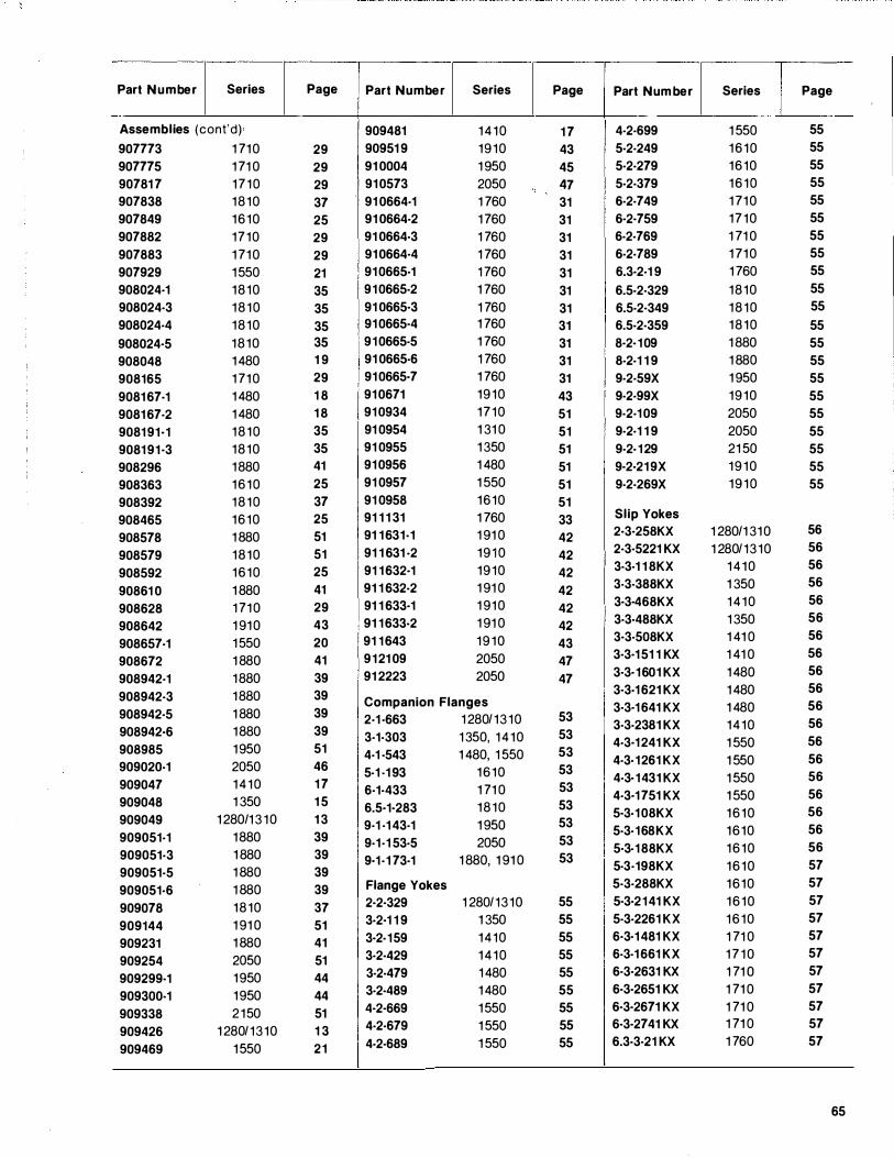
Part Number Series Page Part Number Series Page Part Number Series Page
Assemblies (cont'd) · 909481 1 4 1 0 1 7 4·2·699 1 550 55
907773 1 71 0 29 90951 9 1 9 1 0 43 5·2·249 1 6 1 0 55
907775 1 71 0 29 91 0004 1 950 45 5·2·279 1 6 1 0 55
90781 7 1 7 1 0 29 91 0573 2050 47 5·2·379 1 6 1 0 55
907838 1 8 1 0 37 . 91 0664·1 1 760 31 6·2·749 1 71 0 55
907849 1 6 1 0 25 91 0664·2 1 760 31 6·2·759 1 7 1 0 55
907882 1 7 1 0 29 91 0664·3 1 760 31 6·2·769 1 71 0 55
907883 1 71 0 29 91 0664·4 1 760 31 6·2·789 1 71 0 55
907929 1 550 21 91 0665·1 1 760 31 6.3·2·1 9 1 760 55
908024·1 1 8 1 0 35 91 0665·2 1 760 31 6.5·2·329 1 8 1 0 55
908024·3 1 8 1 0 35 91 0665·3 1 760 31 6.5·2·349 1 8 1 0 55
908024·4 1 8 1 0 35 91 0665·4 1 760 31 6.5·2·359 1 8 1 0 55
908024·5 1 8 1 0 35 91 0665·5 1 760 31 8·2·109 1 880 55
908048 1 480 1 9 91 0665·6 1 760 31 8·2·1 1 9 1 880 55
908165 1 71 0 29 91 0665·7 1 760 31 9·2·59X 1 950 55
9081 67·1 1 480 1 8 91 0671 1 9 1 0 43 9·2·99X 1 9 1 0 55
9081 67·2 1 480 1 8 91 0934 1 7 1 0 51 9·2·1 09 2050 55
9081 91·1 1 8 1 0 35 91 0954 1 31 0 51 9·2·1 1 9 2050 55
9081 91·3 1 8 1 0 35 91 0955 1 350 51 9·2· 1 29 21 50 55
908296 1 880 41 91 0956 1 480 51 9·2·21 9X 1 9 1 0 55
908363 1 6 1 0 25 91 0957 1 550 51 9·2·269X 1 9 1 0 55
908392 1 8 1 0 37 91 0958 1 6 1 0 51
908465 1 6 1 0 25 91 1 1 31 1 760 33 Slip Yokes
908578 1 880 51 91 1 631·1 1 91 0 42 2·3·258KX 1 280/1 31 0 56
908579 1 8 1 0 51 91 1 631 ·2 1 9 1 0 42 2·3·5221 KX 1 280/ 1 3 1 0 56
908592 1 6 1 0 25 91 1 632·1 1 9 1 0 42 3·3·1 1 8KX 1 4 1 0 56
90861 0 1 880 41 91 1 632·2 1 91 0 42 3·3·388KX 1 350 56
908628 1 71 0 29 91 1 633·1 1 91 0 42 3·3·468KX 1 4 1 0 56
908642 1 91 0 43 91 1 633·2 1 91 0 42 3·3·488KX 1 350 56
908657·1 1 550 20 91 1 643 1 9 1 0 43 3·3·508KX 1 41 0 56
908672 1 880 41 9 1 21 09 2050 47 3·3·151 1 KX 1 41 0 56
908942·1 1 880 39 91 2223 2050 47 3·3·1601 KX 1 480 56
908942·3 1 880 39 3·3·1 621 KX 1 480 56
908942·5 1 880 39 Companion Flanges 3·3·1641 KX 1 480 56 2·1 ·663 1 280/ 1 3 1 0 53
3·3·2381 KX 1 4 1 0 56 908942·6 1 880 39 53 3·1·303 1 350, 1 4 1 0 4·3·1 241 KX 1 550 56 908985 1 950 51 53 4·1 ·543 1 480, 1 550 4·3·1261 KX 1 550 56 909020·1 2050 46 5-1 -1 93 1 6 1 0 53
4·3·1431 KX 1 550 56 909047 1 4 1 0 1 7 53 6·1·433 1 71 0 4·3·1 751 KX 1 550 56 909048 1 350 1 5 53 6.5·1·283 1 8 1 0 5·3·1 08KX 1 6 1 0 56 909049 1 280/1 3 1 0 1 3 53 9·1 ·1 43·1 1 950 5·3·168KX 1 6 1 0 56 909051·1 1 880 39 53 9·1·1 53·5 2050 5·3·1 88KX 1 6 1 0 56 909051·3 1 880 39 53 9·1·1 73·1 1 880, 1 91 0 5·3·198KX 1 6 1 0 57 909051·5 1 880 39
909051·6 1 880 39 Flange Yokes 5·3·288KX 1 6 1 0 57
909078 1 8 1 0 37 2·2·329 1 280/ 1 3 1 0 55 5·3·2141 KX 1 6 1 0 57
909144 1 91 0 51 3·2·1 1 9 1 350 55 5·3·2261 KX 1 6 1 0 57
909231 1 880 41 3·2·159 1 4 1 0 55 6·3·1 481 KX 1 71 0 57
909254 2050 51 3·2·429 1 4 1 0 55 6·3·1 661 KX 1 7 1 0 57
909299·1 1 950 44 3·2·479 1 480 55 6·3·2631 KX 1 71 0 57
909300·1 1 950 44 3·2·489 1 480 55 6·3·2651 KX 1 71 0 57
909338 2 1 50 51 4·2·669 1 550 55 6·3·2671 KX 1 71 0 57
909426 1 280/ 1 3 1 0 1 3 4·2·679 1 550 55 6·3·2741 KX 1 71 0 57
909469 1 550 21 4·2·689 1 550 55 6.3·3·21 KX 1 760 57
65
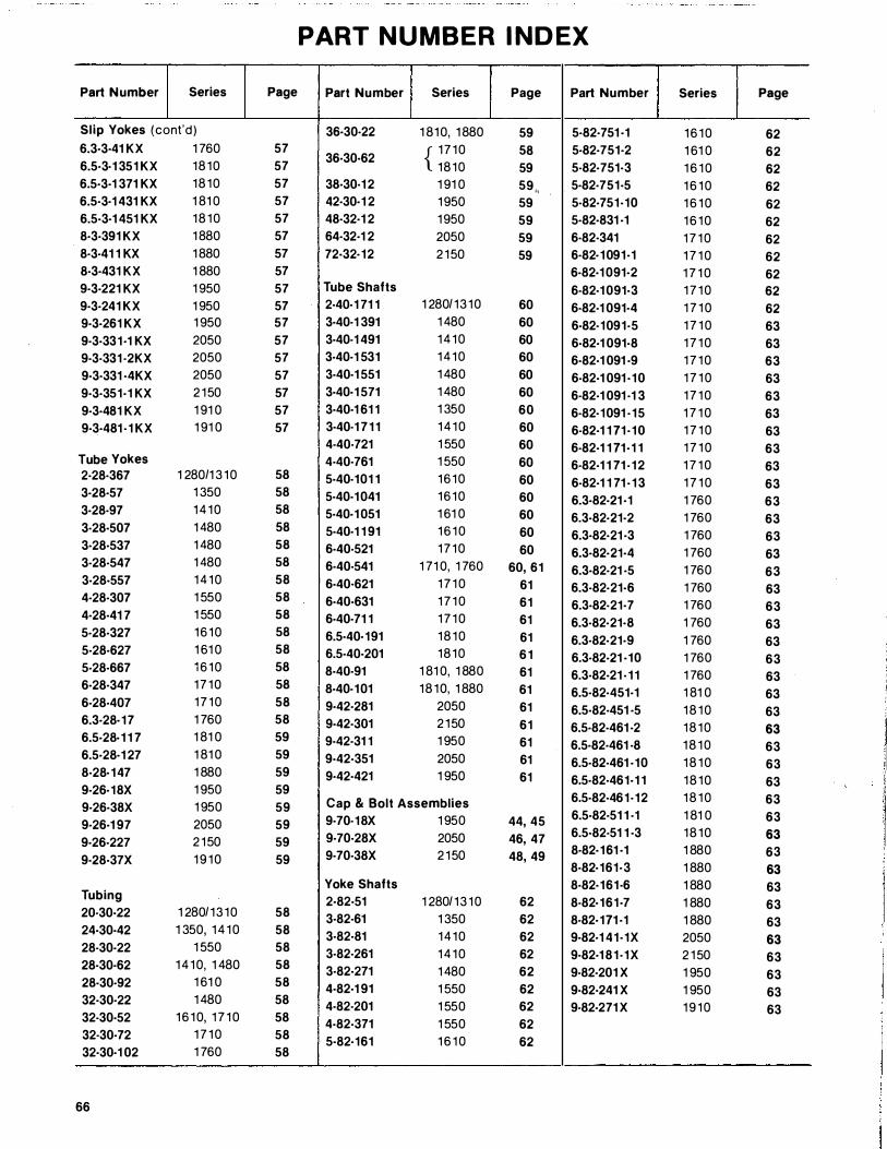
PART N U MBER I ND EX
Part Number Series Page Part Number Series Page Part Number Series Page
Slip Yokes (cont'd ) 36·30-22 1 810, 1 880 59 5·82·751 ·1 1 6 10 62 6.3·3·41 KX 1 760 57 { 1 7 10 58 5·82·751·2 1 61 0 62 6.5·3·1 351 KX 18 10 57
36·30·62 18 10 59 5-82·751·3 1 6 1 0 62
6.5·3·1 371 KX 18 10 57 38·30-1 2 1 91 0 59,, 5·82·751·5 1 6 1 0 62 6.5·3·1 431 KX 1 81 0 57 42·30·1 2 1 950 59 5·82·751·10 1 6 1 0 62 6.5·3·1 451 KX 18 10 57 48·32·1 2 1 950 59 5·82·831 ·1 1 6 10 62 8·3·391 KX 1 880 57 64·32·1 2 2050 59 6-82·341 1 7 1 0 62 8·3·41 1 KX 1 880 57 72·32·12 2 150 59 6-82·1091·1 1 7 1 0 62 8·3·431 KX 1 880 57 6·82·1 091·2 1 7 1 0 62 9·3·221 KX 1 950 57 Tube Shafts 6-82·1 091·3 1 7 1 0 62 9·3·241 KX 1 950 57 2·40-1 71 1 1 280/ 13 10 60 6·82·1 091·4 1 7 1 0 62 9·3·261 KX 1 950 57 3·40-1 391 1 480 60 6·82·1091·5 1 7 1 0 63 9·3·331·1 KX 2050 57 3·40-1 491 14 10 60 6·82·1 091·8 1 7 1 0 63 9·3·331 -2KX 2050 57 3·40-1 531 14 10 60 6·82·1 091 ·9 1 7 1 0 63 9·3·331 ·4KX 2050 57 3·40·1 551 1 480 60 6-82·1 091 ·10 1 7 1 0 63 9·3·351·1 KX 2 150 57 3·40·1 571 1 480 60 6-82·1 091 ·1 3 1 7 1 0 63 9·3·481 KX 1 91 0 57 3·40·1 61 1 1 350 60 6-82·1091 ·15 1 7 1 0 63 9·3·481 - 1 KX 1 91 0 57 3·40-1 7 1 1 14 10 60 6-82·1 1 11·10 1 7 1 0 63
4-40-721 1 550 60 6-82·1 1 11·1 1 1 7 1 0 63 Tube Yokes 4-40-761 1 550 60 6-82·1 1 71 - 1 2 1 7 1 0 63 2·28·367 1 280/1 3 10 58 5·40-101 1 16 10 60 6-82·1 1 71 · 1 3 1 7 1 0 63 3·28·57 1 350 58 5·40·1041 16 10 60 6.3·82·21 ·1 1 760 63 3·28·97 14 10 58 5·40·1 051 1 61 0 60 6.3·82·21·2 1 760 63 3·28·507 1 480 58 5·40·1 1 91 1 6 10 60 6.3·82·21 ·3 1 760 63 3·28·537 1 480 58 6·40·521 1 7 10 60 6.3·82·21·4 1 760 63 3·28·547 1 480 58 6·40-541 1 71 0, 1 760 60, 61 6.3·82·21 ·5 1 760 63 3·28-557 14 10 58 6·40.621 1 7 1 0 61 6.3·82·21·6 1 760 63 4·28·307 1 550 58 6·40-631 1 7 1 0 61 6.3·82-21·7 1 760 63 4·28·41 7 1 550 58 6·40·71 1 1 7 1 0 61 6.3·82·21·8 1 760 63 5·28·327 16 10 58 6.5·40·191 18 10 61 6.3·82·21·9 1 760 63 5·28·627 1 61 0 58 6.5·40·201 18 10 6 1 6.3·82·21 ·10 1 760 63 5·28·667 16 10 58 8·40·91 1 81 0, 1 880 61 6.3·82·21 - 1 1 1 760 63 6·28·347 1 7 10 58 8·40-101 18 10, 1 880 61 6.5·82·451·1 1 81 0 63 6·28·407 1 7 10 58 9·42·281 2050 61 6.5·82-451 ·5 1 8 1 0 63 6.3·28·17 1 760 58 9·42·301 2 150 61 6.5·82·461 ·2 18 10 63 6.5·28·1 1 7 1 81 0 59 9·42·31 1 1 950 61 6.5·82·461 ·8 1 8 1 0 63 6.5·28·1 27 1 81 0 59 9·42·351 2050 61 6.5·82·461 ·10 1 8 1 0 63 8·28·147 1 880 59 9·42·421 1 950 61 6.5·82·461·1 1 18 10 63 9·26·18X 1 950 59
6.5·82·461-12 1 8 1 0 63 9·26·38X 1 950 59 Cap & Bolt Assemblies
6.5·82·51 1 -1 1 81 0 63 9·26·1 97 2050 59 9·70-18X 1 950 44, 45
6.5·82-51 1 ·3 18 10 63 9·26·227 2 150 59 9·70·28X 2050 46, 47
1 880 8·82·161 ·1 63 9·28·37X 1 9 10 59 9·70-38X 2 150 48, 49
1 880 8·82·161·3 63 Yoke Shafts 8·82·161·6 1 880 63
Tubing 2·82·51 1 280/ 1 3 10 62 8-82·161·7 1 880 63 20-30·22 1 280/ 13 10 58 3·82-61 1 350 62 8-82·111 ·1 1 880 63 24·30·42 1 350, 1 4 10 58 3·82·81 14 10 62 9·82·1 41·1X 2050 63 28-30·22 1 550 58 3·82-261 14 10 62 9·82·1 81 -1X 2 1 50 63 28·30·62 14 10, 1 480 58 3·82·271 1 480 62 9-82·201 X 1 950 63 28·30·92 1 61 0 58 4·82·1 91 1 550 62 9·82·241 X 1 950 63 32·30·22 1 480 58 4·82-201 1 550 62 9-82·271 X 1 9 10 63 32-30·52 1 6 10, 1 7 1 0 58 4·82·371 1 550 62 32-30·72 1 7 1 0 58 . 5·82·161 1 6 1 0 62 32·30·1 02 1 760 58
66
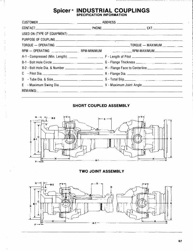
Spicer ® I N D USTR IAL COU PLI NGS SPECIFICATION INFORMATION
CUSTOM ER ____________ ADDRESS ____________ _ CONTACT ___________ PHONE _________ EXT. _____ _ USED O N (TYPE OF EQU IPM ENT)_�--------------------
PURPOSE OF COUPLING ___________ --=--------------"t � TORQUE - OPERATI NG _______________ TORQUE - M AX I M U M ___ _ RPM - OPERATING ______ RPM-M I N I M U M ______ RPM-MAX I M U M _____ _ A-1 - Compressed (M in . Length) _______ F - Length of P i l ot _________ _ B-1 - Bo l t Ho le C i rc le G - F lange Th ickness ________ _ B-2 - Bo l t Ho le D ia. & N u m ber H - Flange Face to Center l ine ______ _ C - P i lot D ia. R - F lange D ia. __________ _ D - Tube D ia. & S ize S - Total S l i p ___________ _ E - M aximum Swing D ia. V - M aximum J oint Angle _______ _ REMARKS: ____________________________ _
SHORT COUPLED ASSEMBLY
TWO JOINT ASSEMBLY
67
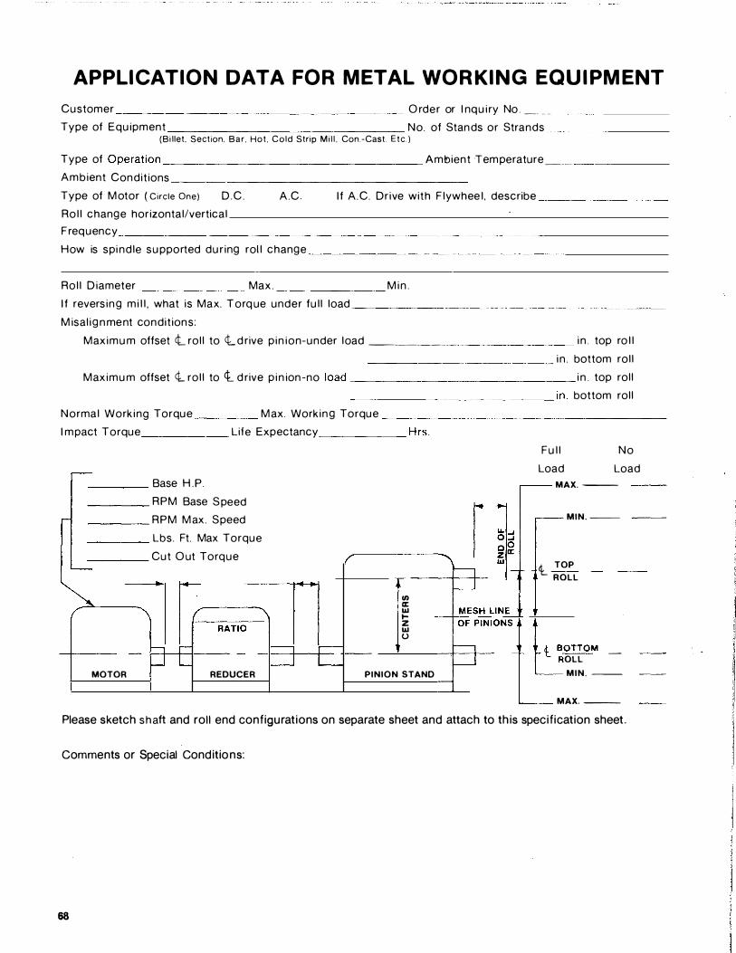
A PPL I CAT ION DAT A FO R MET A L WO R KI N G EQ U I PMENT
Customer ______________________ O rder or I nq u i ry No _ ___ _ _ T ype of Equipment No. of Stands or Strands
(Bi llet. Section. Bar . Hot . Cold Strip Mi l l , Con_-Cast. Etc ) T ype of Operat ion------------------- A mbient Tem perature � _ _ _ A m b ient Condit ions _____________________ _ T ype of M otor ( Circle One) D . C. A.C. I f A . C. Dr ive with Flywheel , describe _________ _ Rol l change horizontal/vertical
F req uency ____________________ __________ _ H ow is spi ndle supported dur ing roll change ________________ __ _
Roll D iameter ________ Max. ________ M i n .
I f revers i n g m i l l , what is Max. T orq ue under full load ______ _ M isal i g n me nt condit ions:
Max i m u m offset <l roll to <l d rive p i n i o n-under l oad ________ _ _ _ _ _____ i n _ top ro l l
_______________ i n. bottom roll
Max i m u m offset <l roll to <t d rive p i n ion-no l oad _____ _ ________ i n _ top roll
Normal Work i ng T orque _____ M ax. Work i n g T orque _____ _ I m pact T orque Life Expectancy _____ � H rs.
____ Base H.P .
____ RPM Base S peed
____ RPM M ax. Speed
_____ Lbs. Ft. Max T orque
_____ Cut O ut T orq ue
� RATIOW MOTOR REDUCER
1/) a: w ... z w u
PINION STAND
��- i n . bottom roll
-------------------
Ful l No
Load Load
MAX. ---
MIN. --
4__ TOP
ROLL
60TTOM _ OLL
MIN. --MAX. --
Piease sketch shaft and roll end configurations on separate sheet and attach to this specification sheet.
Comments or Special Conditions:
68
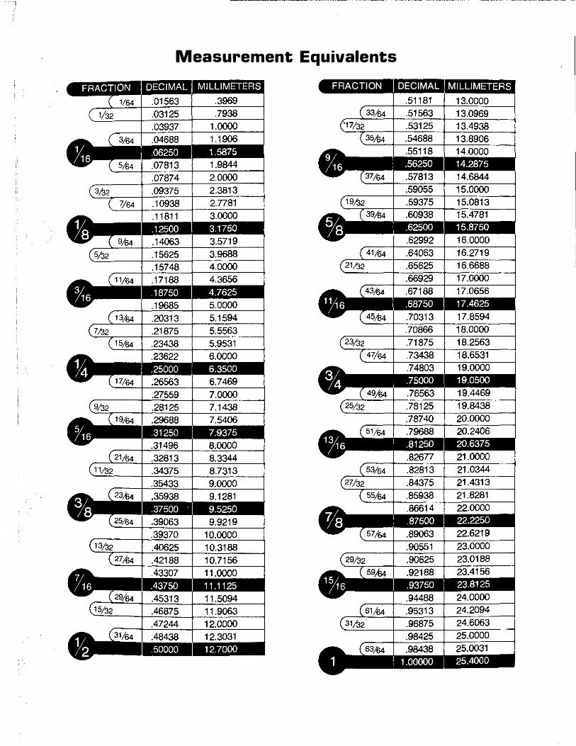
Measurement Equivalents F RACTION DECIMA L
<$> DRIVETRAIN SERVICE DIVISION
DANA CORPORATION, P.O. BOX 321 , TOLEDO, OHIO 43697