Embed Size (px)
Citation preview

Universal GaugeMeasuring System
USERS MANUAL
2002 © Chief Automotive Technologies, Inc.


Chief’s Limited One-YearWarranty & Liability
CHIEF'S LIMITED ONE-YEAR
WARRANTY & LIABILITY
Chief Automotive Technologies, Inc. warrants for one year from date of installation
and/or purchase any of its products which do not perform satisfactorily due to defect
caused by faulty material or workmanship. Chief’s obligation under this warranty is
limited to the repair or replacement of products which are defective and which have not
been misused, carelessly handled, or defaced by repair or repairs made or attempted by
others.
CHIEF AUTOMOTIVE TECHNOLOGIES, INC. DOES NOT ASSUME
RESPONSIBILITY FOR ANY DEATH, INJURY OR PROPERTY DAMAGE
RESULTING FROM THE OPERATOR’S NEGLIGENCE OR MISUSE OF THIS
PRODUCT OR ITS ATTACHMENTS. CHIEF MAKES NO WRITTEN,
EXPRESS OR IMPLIED WARRANTY WHATSOEVER OF MERCHANTABIL-
ITY OR FITNESS FOR A PARTICULAR PURPOSE OR OTHERWISE
REGARDING THE EQUIPMENT OR ANY PART OF THE PRODUCT OTHER
THAN THE LIMITED ONE-YEAR WARRANTY STATED ABOVE.
UNIVERSAL GAUGE MEASURING SYSTEMUSERS MANUAL
I. Introduction
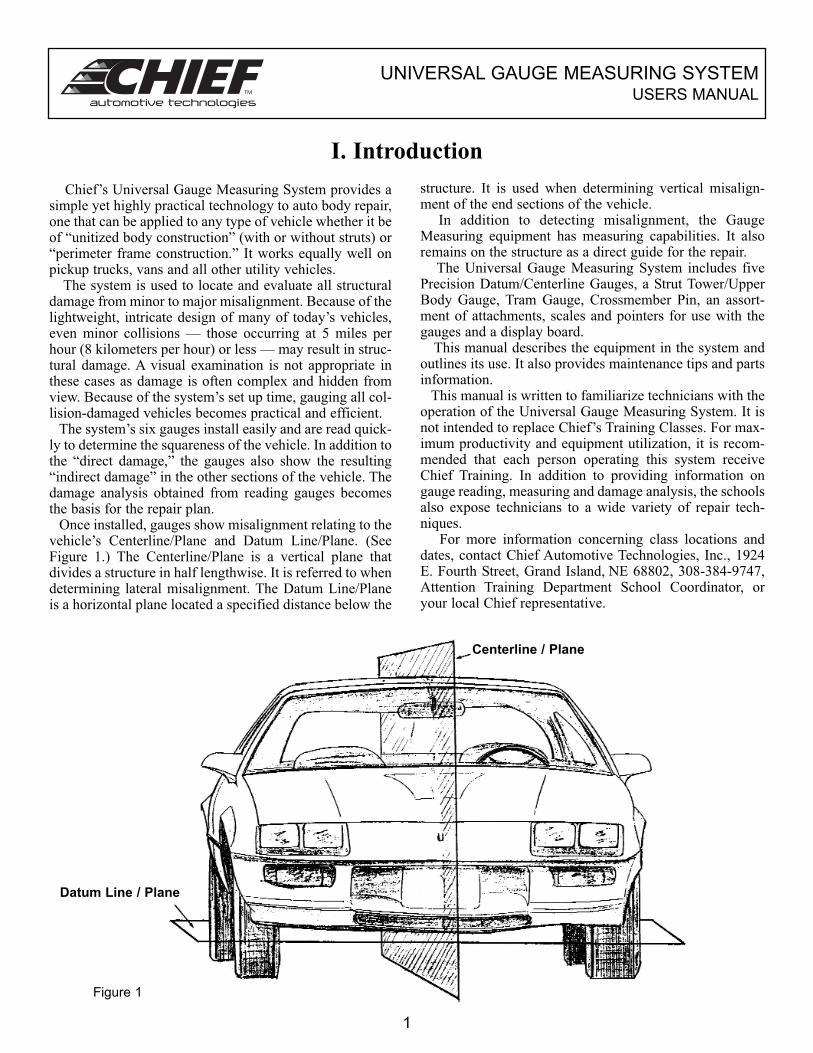
Chief’s Universal Gauge Measuring System provides asimple yet highly practical technology to auto body repair,one that can be applied to any type of vehicle whether it beof “unitized body construction” (with or without struts) or“perimeter frame construction.” It works equally well onpickup trucks, vans and all other utility vehicles.
The system is used to locate and evaluate all structuraldamage from minor to major misalignment. Because of thelightweight, intricate design of many of today’s vehicles,even minor collisions — those occurring at 5 miles perhour (8 kilometers per hour) or less — may result in struc-tural damage. A visual examination is not appropriate inthese cases as damage is often complex and hidden fromview. Because of the system’s set up time, gauging all col-lision-damaged vehicles becomes practical and efficient.
The system’s six gauges install easily and are read quick-ly to determine the squareness of the vehicle. In addition tothe “direct damage,” the gauges also show the resulting“indirect damage” in the other sections of the vehicle. Thedamage analysis obtained from reading gauges becomesthe basis for the repair plan.
Once installed, gauges show misalignment relating to thevehicle’s Centerline/Plane and Datum Line/Plane. (SeeFigure 1.) The Centerline/Plane is a vertical plane thatdivides a structure in half lengthwise. It is referred to whendetermining lateral misalignment. The Datum Line/Planeis a horizontal plane located a specified distance below the
structure. It is used when determining vertical misalign-ment of the end sections of the vehicle.
In addition to detecting misalignment, the GaugeMeasuring equipment has measuring capabilities. It alsoremains on the structure as a direct guide for the repair.
The Universal Gauge Measuring System includes fivePrecision Datum/Centerline Gauges, a Strut Tower/UpperBody Gauge, Tram Gauge, Crossmember Pin, an assort-ment of attachments, scales and pointers for use with thegauges and a display board.
This manual describes the equipment in the system andoutlines its use. It also provides maintenance tips and partsinformation.
This manual is written to familiarize technicians with theoperation of the Universal Gauge Measuring System. It isnot intended to replace Chief’s Training Classes. For max-imum productivity and equipment utilization, it is recom-mended that each person operating this system receiveChief Training. In addition to providing information ongauge reading, measuring and damage analysis, the schoolsalso expose technicians to a wide variety of repair tech-niques.
For more information concerning class locations anddates, contact Chief Automotive Technologies, Inc., 1924E. Fourth Street, Grand Island, NE 68802, 308-384-9747,Attention Training Department School Coordinator, oryour local Chief representative.
1
Centerline / Plane
Datum Line / Plane
Figure 1
UNIVERSAL GAUGE MEASURING SYSTEMUSERS MANUAL
III. Universal Gauge Measuring System
Components Terminology
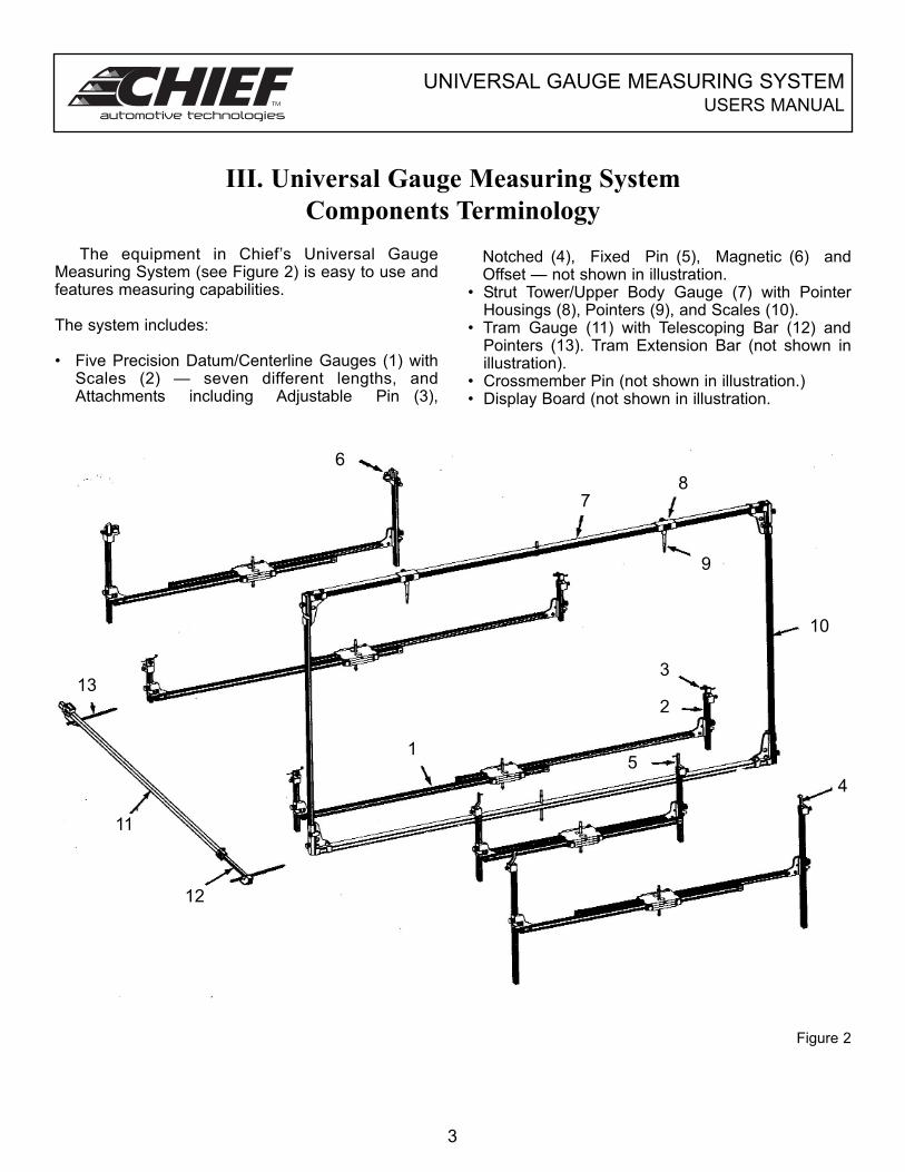
The equipment in Chief’s Universal GaugeMeasuring System (see Figure 2) is easy to use andfeatures measuring capabilities.
The system includes:
• Five Precision Datum/Centerline Gauges (1) withScales (2) — seven different lengths, andAttachments including Adjustable Pin (3),
Notched (4), Fixed Pin (5), Magnetic (6) andOffset — not shown in illustration.
• Strut Tower/Upper Body Gauge (7) with PointerHousings (8), Pointers (9), and Scales (10).
• Tram Gauge (11) with Telescoping Bar (12) andPointers (13). Tram Extension Bar (not shown inillustration).
• Crossmember Pin (not shown in illustration.)• Display Board (not shown in illustration.
3
Figure 2
12
13
7
9
1
3
10
11
6
5
2
4
8
UNIVERSAL GAUGE MEASURING SYSTEMUSERS MANUAL
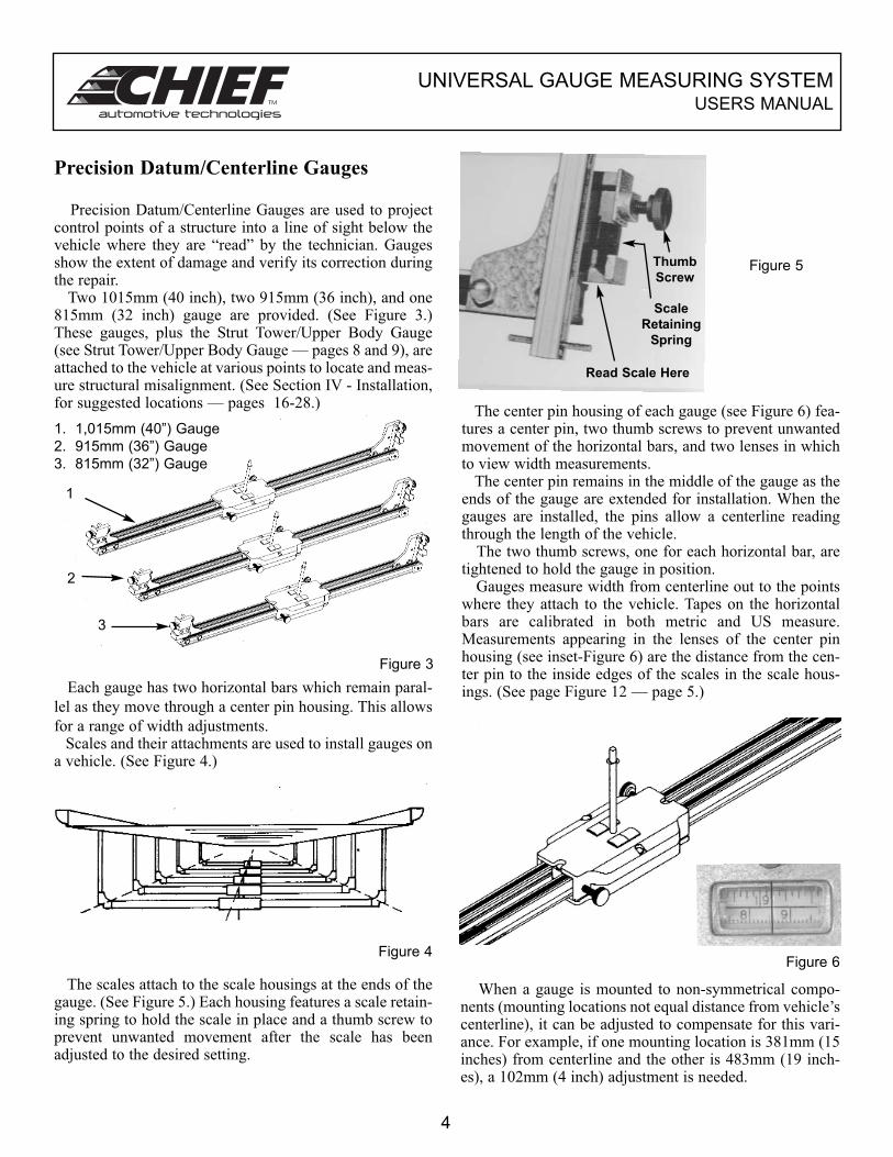
Precision Datum/Centerline Gauges
Precision Datum/Centerline Gauges are used to projectcontrol points of a structure into a line of sight below thevehicle where they are “read” by the technician. Gaugesshow the extent of damage and verify its correction duringthe repair.
Two 1015mm (40 inch), two 915mm (36 inch), and one815mm (32 inch) gauge are provided. (See Figure 3.)These gauges, plus the Strut Tower/Upper Body Gauge(see Strut Tower/Upper Body Gauge — pages 8 and 9), areattached to the vehicle at various points to locate and meas-ure structural misalignment. (See Section IV - Installation,for suggested locations — pages 16-28.)
Each gauge has two horizontal bars which remain paral-
lel as they move through a center pin housing. This allows
for a range of width adjustments.Scales and their attachments are used to install gauges on
a vehicle. (See Figure 4.)
The scales attach to the scale housings at the ends of thegauge. (See Figure 5.) Each housing features a scale retain-ing spring to hold the scale in place and a thumb screw toprevent unwanted movement after the scale has beenadjusted to the desired setting.
Figure 3
Figure 4
Figure 5
The center pin housing of each gauge (see Figure 6) fea-tures a center pin, two thumb screws to prevent unwantedmovement of the horizontal bars, and two lenses in whichto view width measurements.
The center pin remains in the middle of the gauge as theends of the gauge are extended for installation. When thegauges are installed, the pins allow a centerline readingthrough the length of the vehicle.
The two thumb screws, one for each horizontal bar, aretightened to hold the gauge in position.
Gauges measure width from centerline out to the pointswhere they attach to the vehicle. Tapes on the horizontalbars are calibrated in both metric and US measure.Measurements appearing in the lenses of the center pinhousing (see inset-Figure 6) are the distance from the cen-ter pin to the inside edges of the scales in the scale hous-ings. (See page Figure 12 — page 5.)
Figure 6
When a gauge is mounted to non-symmetrical compo-nents (mounting locations not equal distance from vehicle’scenterline), it can be adjusted to compensate for this vari-ance. For example, if one mounting location is 381mm (15inches) from centerline and the other is 483mm (19 inch-es), a 102mm (4 inch) adjustment is needed.
4
1. 1,015mm (40”) Gauge
2. 915mm (36”) Gauge
3. 815mm (32”) Gauge
1
2
3
Thumb
Screw
Scale
Retaining
Spring
Read Scale Here
UNIVERSAL GAUGE MEASURING SYSTEMUSERS MANUAL
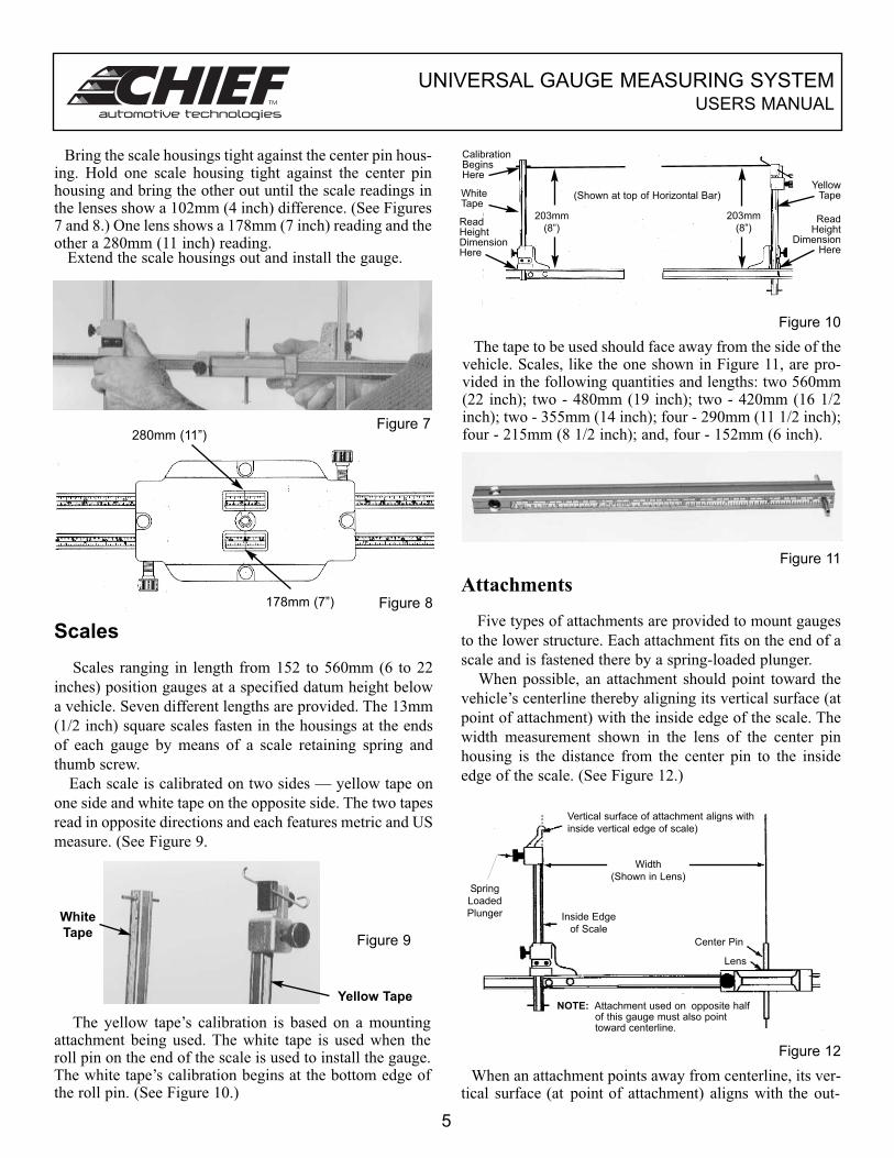
Bring the scale housings tight against the center pin hous-ing. Hold one scale housing tight against the center pinhousing and bring the other out until the scale readings inthe lenses show a 102mm (4 inch) difference. (See Figures7 and 8.) One lens shows a 178mm (7 inch) reading and theother a 280mm (11 inch) reading.
Extend the scale housings out and install the gauge.
Figure 7
Figure 8
Scales
Scales ranging in length from 152 to 560mm (6 to 22
inches) position gauges at a specified datum height below
a vehicle. Seven different lengths are provided. The 13mm
(1/2 inch) square scales fasten in the housings at the ends
of each gauge by means of a scale retaining spring and
thumb screw.
Each scale is calibrated on two sides — yellow tape on
one side and white tape on the opposite side. The two tapes
read in opposite directions and each features metric and US
measure. (See Figure 9.
The yellow tape’s calibration is based on a mountingattachment being used. The white tape is used when theroll pin on the end of the scale is used to install the gauge.The white tape’s calibration begins at the bottom edge ofthe roll pin. (See Figure 10.)
Figure 9
Figure 10
The tape to be used should face away from the side of thevehicle. Scales, like the one shown in Figure 11, are pro-vided in the following quantities and lengths: two 560mm(22 inch); two - 480mm (19 inch); two - 420mm (16 1/2inch); two - 355mm (14 inch); four - 290mm (11 1/2 inch);four - 215mm (8 1/2 inch); and, four - 152mm (6 inch).
Figure 11
Attachments
Five types of attachments are provided to mount gauges
to the lower structure. Each attachment fits on the end of a
scale and is fastened there by a spring-loaded plunger.
When possible, an attachment should point toward the
vehicle’s centerline thereby aligning its vertical surface (at
point of attachment) with the inside edge of the scale. The
width measurement shown in the lens of the center pin
housing is the distance from the center pin to the inside
edge of the scale. (See Figure 12.)
Figure 12
When an attachment points away from centerline, its ver-tical surface (at point of attachment) aligns with the out-
5
280mm (11”)
178mm (7”)
White
Tape
Yellow Tape
Yellow Tape
ReadHeight
DimensionHere
CalibrationBeginsHere
ReadHeightDimensionHere
WhiteTape
(Shown at top of Horizontal Bar)
203mm
(8”)
203mm
(8”)
Vertical surface of attachment aligns with
inside vertical edge of scale)
Width
(Shown in Lens)Spring
Loaded
Plunger Inside Edge
of Scale
Center Pin
Lens
NOTE: Attachment used on opposite halfof this gauge must also pointtoward centerline.
UNIVERSAL GAUGE MEASURING SYSTEMUSERS MANUAL
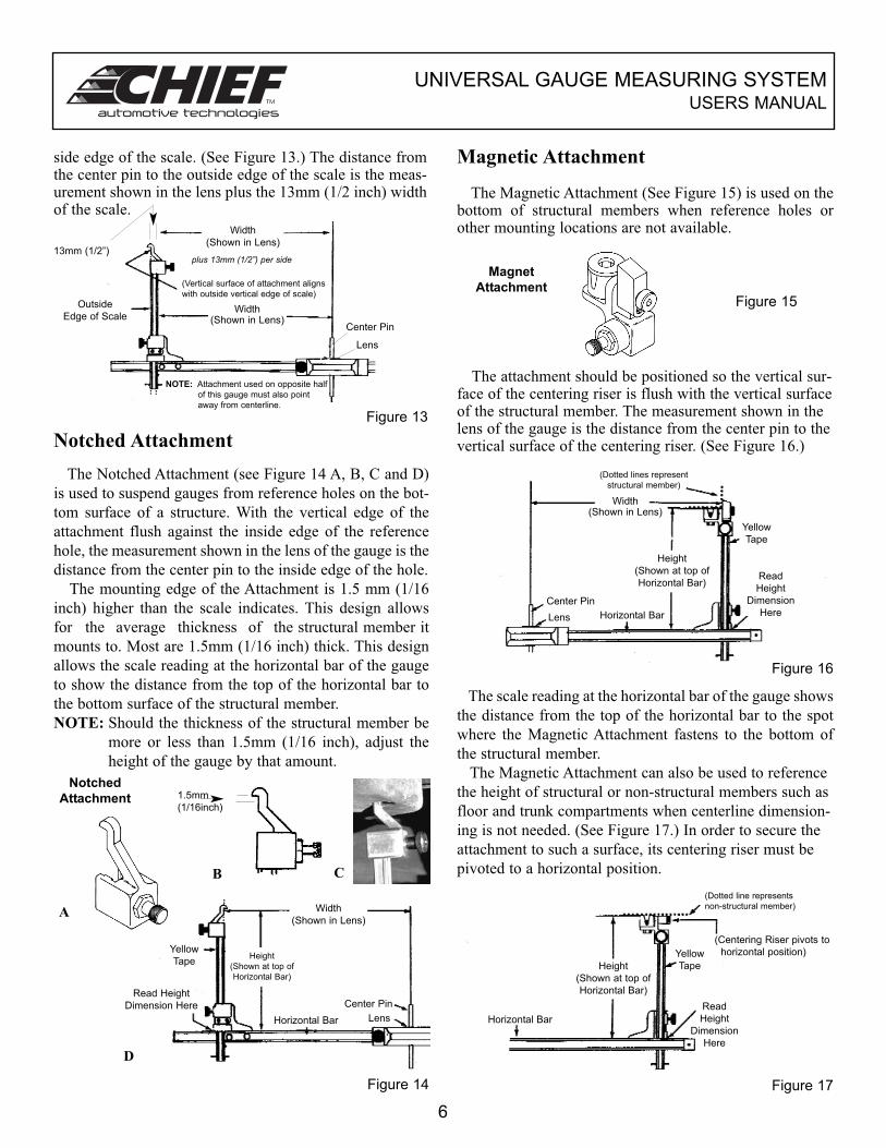
side edge of the scale. (See Figure 13.) The distance fromthe center pin to the outside edge of the scale is the meas-urement shown in the lens plus the 13mm (1/2 inch) widthof the scale.
Figure 13
Notched Attachment
The Notched Attachment (see Figure 14 A, B, C and D)
is used to suspend gauges from reference holes on the bot-
tom surface of a structure. With the vertical edge of the
attachment flush against the inside edge of the reference
hole, the measurement shown in the lens of the gauge is the
distance from the center pin to the inside edge of the hole.
The mounting edge of the Attachment is 1.5 mm (1/16
inch) higher than the scale indicates. This design allows
for the average thickness of the structural member it
mounts to. Most are 1.5mm (1/16 inch) thick. This design
allows the scale reading at the horizontal bar of the gauge
to show the distance from the top of the horizontal bar to
the bottom surface of the structural member.
NOTE: Should the thickness of the structural member be
more or less than 1.5mm (1/16 inch), adjust the
height of the gauge by that amount.
C
Figure 14
D
Magnetic Attachment
The Magnetic Attachment (See Figure 15) is used on thebottom of structural members when reference holes orother mounting locations are not available.
Figure 15
The attachment should be positioned so the vertical sur-face of the centering riser is flush with the vertical surfaceof the structural member. The measurement shown in thelens of the gauge is the distance from the center pin to thevertical surface of the centering riser. (See Figure 16.)
Figure 16
The scale reading at the horizontal bar of the gauge shows
the distance from the top of the horizontal bar to the spot
where the Magnetic Attachment fastens to the bottom of
the structural member.
The Magnetic Attachment can also be used to reference
the height of structural or non-structural members such as
floor and trunk compartments when centerline dimension-
ing is not needed. (See Figure 17.) In order to secure the
attachment to such a surface, its centering riser must be
pivoted to a horizontal position.
Figure 17
6
B
1.5mm
(1/16inch)
Width
(Shown in Lens)
(Vertical surface of attachment aligns
with outside vertical edge of scale)
plus 13mm (1/2”) per side
Width(Shown in Lens)
Center Pin
Lens
Outside
Edge of Scale
13mm (1/2”)
NOTE: Attachment used on opposite half
of this gauge must also point
away from centerline.
Width
(Shown in Lens)
Height
(Shown at top of
Horizontal Bar)
Horizontal Bar
Center Pin
Lens
Yellow
Tape
Read Height
Dimension Here
(Dotted lines represent
structural member)
Width(Shown in Lens)
Height
(Shown at top of
Horizontal Bar)
Horizontal Bar
Center Pin
Lens
Yellow
Tape
Read
Height
Dimension
Here
(Dotted line represents
non-structural member)
Horizontal Bar
Yellow
Tape
(Centering Riser pivots to
horizontal position)
Read
Height
Dimension
Here
Height
(Shown at top of
Horizontal Bar)
Magnet
Attachment
Notched
Attachment
A
UNIVERSAL GAUGE MEASURING SYSTEMUSERS MANUAL
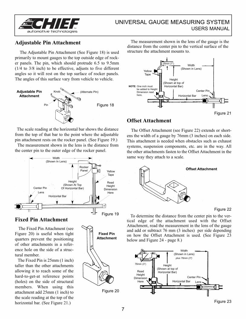
Adjustable Pin Attachment
The Adjustable Pin Attachment (See Figure 18) is used
primarily to mount gauges to the top outside edge of rock-
er panels. The pin, which should protrude 6.5 to 9.5mm
(1/4 to 3/8 inch) to be effective, adjusts to five different
angles so it will rest on the top surface of rocker panels.
The angles of this surface vary from vehicle to vehicle.
Figure 18
The scale reading at the horizontal bar shows the distance
from the top of that bar to the point where the adjustable
pin attachment rests on the rocker panel. (See Figure 19.)
The measurement shown in the lens is the distance from
the center pin to the outer edge of the rocker panel.
Figure 19
Fixed Pin Attachment
The Fixed Pin Attachment (see
Figure 20) is useful when tight
quarters prevent the positioning
of other attachments in a refer-
ence hole on the side of a struc-
tural member.
The Fixed Pin is 25mm (1 inch)
taller than the other attachments
allowing it to reach some of the
hard-to-get-at reference points
(holes) on the side of structural
members. When using this
attachment add 25mm (1 inch) to
the scale reading at the top of the
horizontal bar. (See Figure 21.)
Figure 20
The measurement shown in the lens of the gauge is thedistance from the center pin to the vertical surface of thestructure the attachment mounts to.
Figure 21
Offset Attachment
The Offset Attachment (see Figure 22) extends or short-
ens the width of a gauge by 76mm (3 inches) on each side.
This attachment is needed when obstacles such as exhaust
systems, suspension components, etc. are in the way. All
the other attachments fasten to the Offset Attachment in the
same way they attach to a scale.
Figure 22
To determine the distance from the center pin to the ver-tical edge of the attachment used with the OffsetAttachment, read the measurement in the lens of the gaugeand add or subtract 76 mm (3 inches) per side dependingon how the Offset Attachment is used. (See Figure 23below and Figure 24 - page 8.)
Figure 23
7
Pin
Knob (Alternate Pin)
Width
(Shown In Lens)
Height
(Shown At Top
Of Horizontal Bar)Center Pin
Lens
Horizontal Bar
Yellow
Tape
Read
Height
Dimension
Here
Rocker
Panel
Width
(Shown in Lens)
25mm (1”)
Height
(Shown at top of
Horizontal Bar)
Center Pin
LensHorizontal Bar
Yellow
Tape
NOTE: One inch must
be added to Height
Dimension read
here.
Width
(Shown in Lens)
plus 76mm (3”)
Height
(Shown at top of
Horizontal Bar)
Center Pin
LensHorizontal Bar
Read
Height
Dimension
Here
76mm (3”)
Adjustable Pin
Attachment
Fixed Pin
Attachment
Offset Attachment
UNIVERSAL GAUGE MEASURING SYSTEMUSERS MANUAL
Figure 24
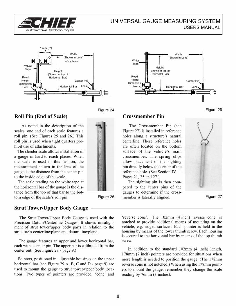
Roll Pin (End of Scale)
As noted in the description of the
scales, one end of each scale features a
roll pin. (See Figures 25 and 26.) This
roll pin is used when tight quarters pro-
hibit use of attachments.
The slender scale allows installation of
a gauge in hard-to-reach places. When
the scale is used in this fashion, the
measurement shown in the lens of the
gauge is the distance from the center pin
to the inside edge of the scale.
The scale reading on the white tape at
the horizontal bar of the gauge is the dis-
tance from the top of that bar to the bot-
tom edge of the scale’s roll pin. Figure 25
Figure 26
Crossmember Pin
The Crossmember Pin (see
Figure 27) is installed in reference
holes along a structure’s natural
centerline. These reference holes
are often located on the bottom
surface of the vehicle’s main
crossmember. The spring clips
allow placement of the sighting
pin directly below the center of the
reference hole. (See Section IV —
Pages 21, 25 and 27.)
The sighting pin is then com-
pared to the center pins of the
gauges to determine if the cross-
member is laterally aligned. Figure 27
Strut Tower/Upper Body Gauge
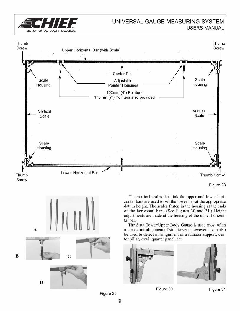
The Strut Tower/Upper Body Gauge is used with thePrecision Datum/Centerline Gauges. It shows misalign-ment of strut tower/upper body parts in relation to thestructure’s centerline/plane and datum line/plane.
The gauge features an upper and lower horizontal bar,each with a center pin. The upper bar is calibrated from thecenter out. (See Figure 28 - page 9.)
Pointers, positioned in adjustable housings on the upper
horizontal bar (see Figure 29 A, B, C and D - page 9) are
used to mount the gauge to strut tower/upper body loca-
tions. Two types of pointers are provided: ‘cone’ and
‘reverse cone’. The 102mm (4 inch) reverse cone isnotched to provide additional means of mounting on thevehicle, e.g. ridged surfaces. Each pointer is held in thehousing by means of the lower thumb screw. Each housingis secured to the horizontal bar by means of the top thumbscrew.
In addition to the standard 102mm (4 inch) length,
178mm (7 inch) pointers are provided for situations when
more length is needed to position the gauge. (The 178mm
reverse cone is not notched.) When using the 178mm point-
ers to mount the gauge, remember they change the scale
reading by 76mm (3 inches).
8
76mm (3”)
Width
(Shown in Lens)
minus 76mm
Height
(Shown at top of
Horizontal Bar)
Horizontal Bar
Center Pin
Lens
Yellow
Tape
Read
Height
Dimension
Here
White
Tape
Height
(Shown at top of
Horizontal Bar)
Center Pin
LensHorizontal Bar
Width
(Shown in Lens)
Read
Height
Dimension
Here
UNIVERSAL GAUGE MEASURING SYSTEMUSERS MANUAL
The vertical scales that link the upper and lower hori-zontal bars are used to set the lower bar at the appropriatedatum height. The scales fasten in the housing at the endsof the horizontal bars. (See Figures 30 and 31.) Heightadjustments are made at the housing of the upper horizon-tal bar.
The Strut Tower/Upper Body Gauge is used most oftento detect misalignment of strut towers; however, it can alsobe used to detect misalignment of a radiator support, cen-ter pillar, cowl, quarter panel, etc.
Figure 30 Figure 31Figure 29
A
B C
D
Figure 28
9
Thumb
Screw
Thumb
Screw
Thumb
Screw
Thumb Screw
Scale
Housing
Scale
Housing
Scale
Housing
Scale
Housing
Vertical
Scale
Vertical
Scale
Upper Horizontal Bar (with Scale)
Lower Horizontal Bar
Center Pin
Adjustable
Pointer Housings
102mm (4”) Pointers
178mm (7”) Pointers also provided
UNIVERSAL GAUGE MEASURING SYSTEMUSERS MANUAL
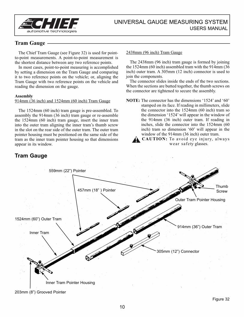
The Chief Tram Gauge (see Figure 32) is used for point-to-point measurements. A point-to-point measurement isthe shortest distance between any two reference points.
In most cases, point-to-point measuring is accomplishedby setting a dimension on the Tram Gauge and comparingit to two reference points on the vehicle; or, aligning theTram Gauge with two reference points on the vehicle andreading the dimension on the gauge.
Assembly914mm (36 inch) and 1524mm (60 inch) Tram Gauge
The 1524mm (60 inch) tram gauge is pre-assembled. Toassembly the 914mm (36 inch) tram gauge or re-assemblethe 1524mm (60 inch) tram gauge, insert the inner traminto the outer tram aligning the inner tram’s thumb screwin the slot on the rear side of the outer tram. The outer trampointer housing must be positioned on the same side of thetram as the inner tram pointer housing so that dimensionsappear in its window.
2438mm (96 inch) Tram Gauge
The 2438mm (96 inch) tram gauge is formed by joiningthe 1524mm (60 inch) assembled tram with the 914mm (36inch) outer tram. A 305mm (12 inch) connector is used tojoin the components.
The connector slides inside the ends of the two sections.When the sections are butted together, the thumb screws onthe connector are tightened to secure the assembly.
NOTE: The connector has the dimensions ‘1524’ and ‘60’stamped on its face. If reading in millimeters, slidethe connector into the 1524mm (60 inch) tram sothe dimension ‘1524’ will appear in the window ofthe 914mm (36 inch) outer tram. If reading ininches, slide the connector into the 1524mm (60inch) tram so dimension ‘60’ will appear in thewindow of the 914mm (36 inch) outer tram.CAUTION: To avoid eye injury, a lways
wear safety glasses.
Tram Gauge
Figure 32
10
Tram Gauge
559mm (22”) Pointer
457mm (18” ) Pointer
1524mm (60”) Outer Tram
Inner Tram
Inner Tram Pointer Housing
203mm (8”) Grooved Pointer
305mm (12”) Connector
914mm (36”) Outer Tram
Thumb
Screw
Outer Tram Pointer Housing
UNIVERSAL GAUGE MEASURING SYSTEMUSERS MANUAL
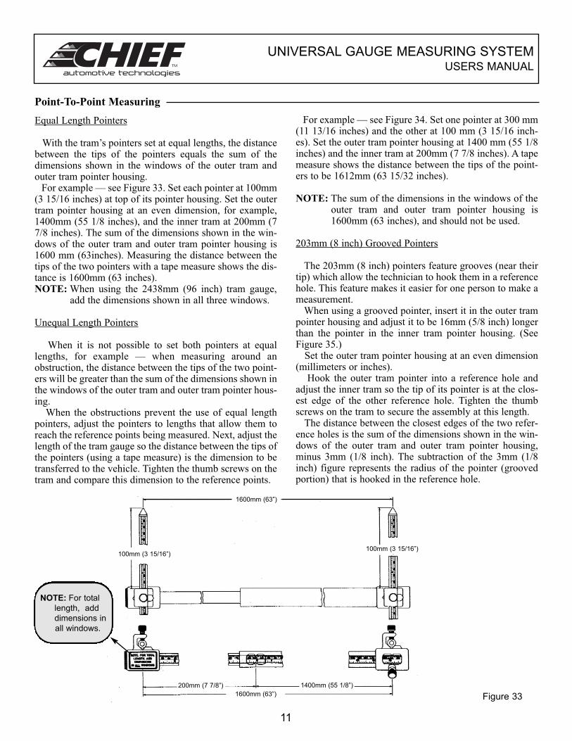
Equal Length Pointers
With the tram’s pointers set at equal lengths, the distancebetween the tips of the pointers equals the sum of thedimensions shown in the windows of the outer tram andouter tram pointer housing.
For example — see Figure 33. Set each pointer at 100mm(3 15/16 inches) at top of its pointer housing. Set the outertram pointer housing at an even dimension, for example,1400mm (55 1/8 inches), and the inner tram at 200mm (77/8 inches). The sum of the dimensions shown in the win-dows of the outer tram and outer tram pointer housing is1600 mm (63inches). Measuring the distance between thetips of the two pointers with a tape measure shows the dis-tance is 1600mm (63 inches).NOTE: When using the 2438mm (96 inch) tram gauge,
add the dimensions shown in all three windows.
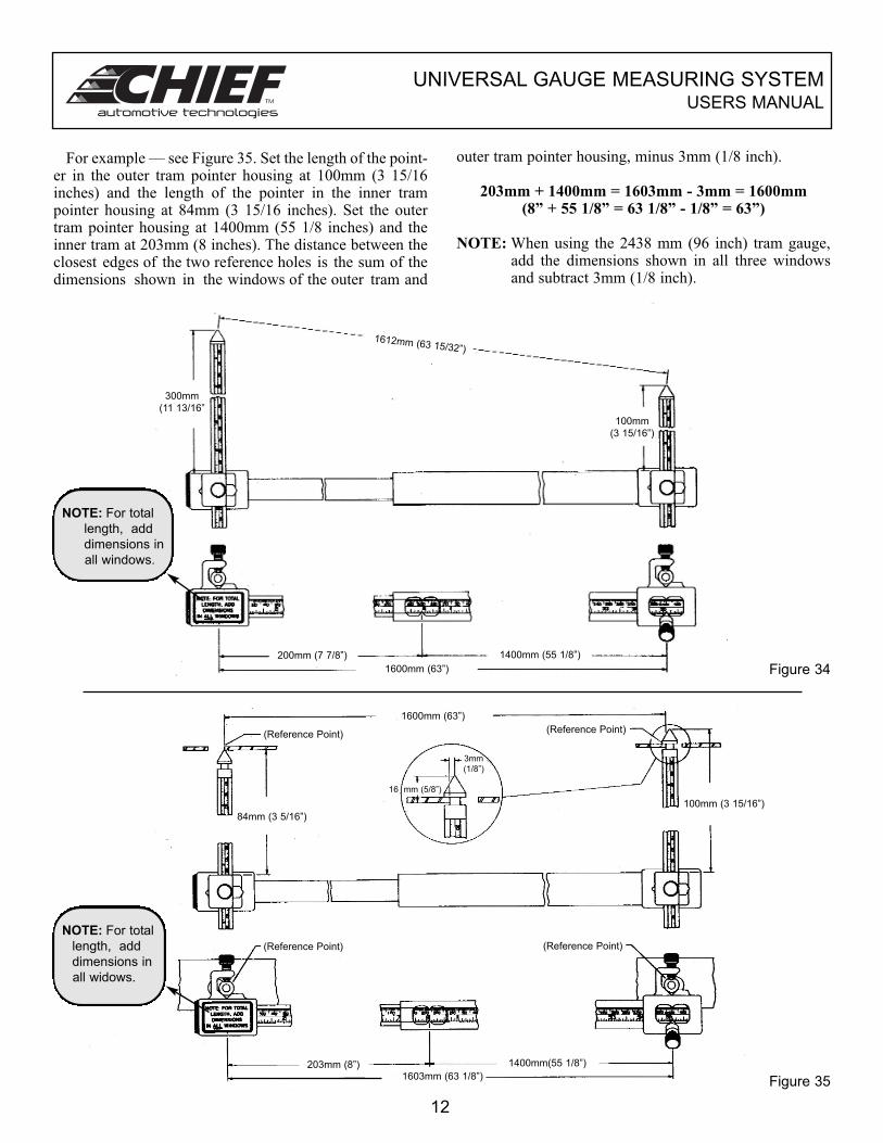
Unequal Length Pointers
When it is not possible to set both pointers at equallengths, for example — when measuring around anobstruction, the distance between the tips of the two point-ers will be greater than the sum of the dimensions shown inthe windows of the outer tram and outer tram pointer hous-ing.
When the obstructions prevent the use of equal lengthpointers, adjust the pointers to lengths that allow them toreach the reference points being measured. Next, adjust thelength of the tram gauge so the distance between the tips ofthe pointers (using a tape measure) is the dimension to betransferred to the vehicle. Tighten the thumb screws on thetram and compare this dimension to the reference points.
For example — see Figure 34. Set one pointer at 300 mm(11 13/16 inches) and the other at 100 mm (3 15/16 inch-es). Set the outer tram pointer housing at 1400 mm (55 1/8inches) and the inner tram at 200mm (7 7/8 inches). A tapemeasure shows the distance between the tips of the point-ers to be 1612mm (63 15/32 inches).
NOTE: The sum of the dimensions in the windows of theouter tram and outer tram pointer housing is1600mm (63 inches), and should not be used.
203mm (8 inch) Grooved Pointers
The 203mm (8 inch) pointers feature grooves (near theirtip) which allow the technician to hook them in a referencehole. This feature makes it easier for one person to make ameasurement.
When using a grooved pointer, insert it in the outer trampointer housing and adjust it to be 16mm (5/8 inch) longerthan the pointer in the inner tram pointer housing. (SeeFigure 35.)
Set the outer tram pointer housing at an even dimension(millimeters or inches).
Hook the outer tram pointer into a reference hole andadjust the inner tram so the tip of its pointer is at the clos-est edge of the other reference hole. Tighten the thumbscrews on the tram to secure the assembly at this length.
The distance between the closest edges of the two refer-ence holes is the sum of the dimensions shown in the win-dows of the outer tram and outer tram pointer housing,minus 3mm (1/8 inch). The subtraction of the 3mm (1/8inch) figure represents the radius of the pointer (groovedportion) that is hooked in the reference hole.
Point-To-Point Measuring
Figure 33
11
1600mm (63”)
100mm (3 15/16”)100mm (3 15/16”)
200mm (7 7/8”) 1400mm (55 1/8”)
1600mm (63”)
NOTE: For total
length, add
dimensions in
all windows.
UNIVERSAL GAUGE MEASURING SYSTEMUSERS MANUAL
For example — see Figure 35. Set the length of the point-er in the outer tram pointer housing at 100mm (3 15/16inches) and the length of the pointer in the inner trampointer housing at 84mm (3 15/16 inches). Set the outertram pointer housing at 1400mm (55 1/8 inches) and theinner tram at 203mm (8 inches). The distance between theclosest edges of the two reference holes is the sum of thedimensions shown in the windows of the outer tram and
outer tram pointer housing, minus 3mm (1/8 inch).
203mm + 1400mm = 1603mm - 3mm = 1600mm (8” + 55 1/8” = 63 1/8” - 1/8” = 63”)
NOTE: When using the 2438 mm (96 inch) tram gauge,add the dimensions shown in all three windowsand subtract 3mm (1/8 inch).
Figure 34
Figure 35
12
1612mm (63 15/32”)
300mm
(11 13/16”
100mm
(3 15/16”)
200mm (7 7/8”) 1400mm (55 1/8”)
1600mm (63”)
(Reference Point)(Reference Point)
1600mm (63”)
84mm (3 5/16”)
100mm (3 15/16”)
3mm
(1/8”)
16 mm (5/8”)
(Reference Point) (Reference Point)
203mm (8”) 1400mm(55 1/8”)
1603mm (63 1/8”)
NOTE: For total
length, add
dimensions in
all windows.
NOTE: For total
length, add
dimensions in
all widows.
UNIVERSAL GAUGE MEASURING SYSTEMUSERS MANUAL
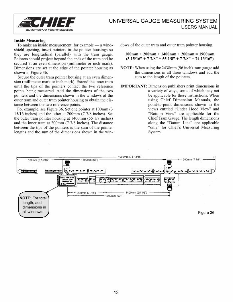
Inside MeasuringTo make an inside measurement, for example — a wind-
shield opening, insert pointers in the pointer housings sothey are longitudinal (parallel) with the tram gauge.Pointers should project beyond the ends of the tram and besecured at an even dimension (millimeter or inch mark).Dimensions are set at the edge of the pointer housing asshown in Figure 36.
Secure the outer tram pointer housing at an even dimen-sion (millimeter mark or inch mark). Extend the inner tramuntil the tips of the pointers contact the two referencepoints being measured. Add the dimensions of the twopointers and the dimensions shown in the windows of theouter tram and outer tram pointer housing to obtain the dis-tance between the two reference points.
For example, see Figure 36. Set one pointer at 100mm (315/16 inches) and the other at 200mm (7 7/8 inches). Setthe outer tram pointer housing at 1400mm (55 1/8 inches)and the inner tram at 200mm (7 7/8 inches). The distancebetween the tips of the pointers is the sum of the pointerlengths and the sum of the dimensions shown in the win-
dows of the outer tram and outer tram pointer housing.
100mm + 200mm + 1400mm + 200mm = 1900mm(3 15/16” + 7 7/8” + 55 1/8” + 7 7/8” = 74 13/16”)
NOTE: When using the 2438mm (96 inch) tram gauge addthe dimensions in all three windows and add thesum to the length of the pointers.
IMPORTANT: Dimension publishers print dimensions ina variety of ways, some of which may notbe applicable for these instructions. Whenusing Chief Dimension Manuals, thepoint-to-point dimensions shown in theviews entitled “Under Hood View” and“Bottom View” are applicable for theChief Tram Gauge. The length dimensionsalong the “Datum Line” are applicable“only” for Chief’s Universal MeasuringSystem.
Figure 36
13
1900mm (74 13/16”1600mm (63”)100mm (3 15/16”) 200mm (7 7/8”)
200mm (7 7/8”) 1400mm (55 1/8”)
1600mm (63”)NOTE: For total
length, add
dimensions in
all windows.
UNIVERSAL GAUGE MEASURING SYSTEMUSERS MANUAL
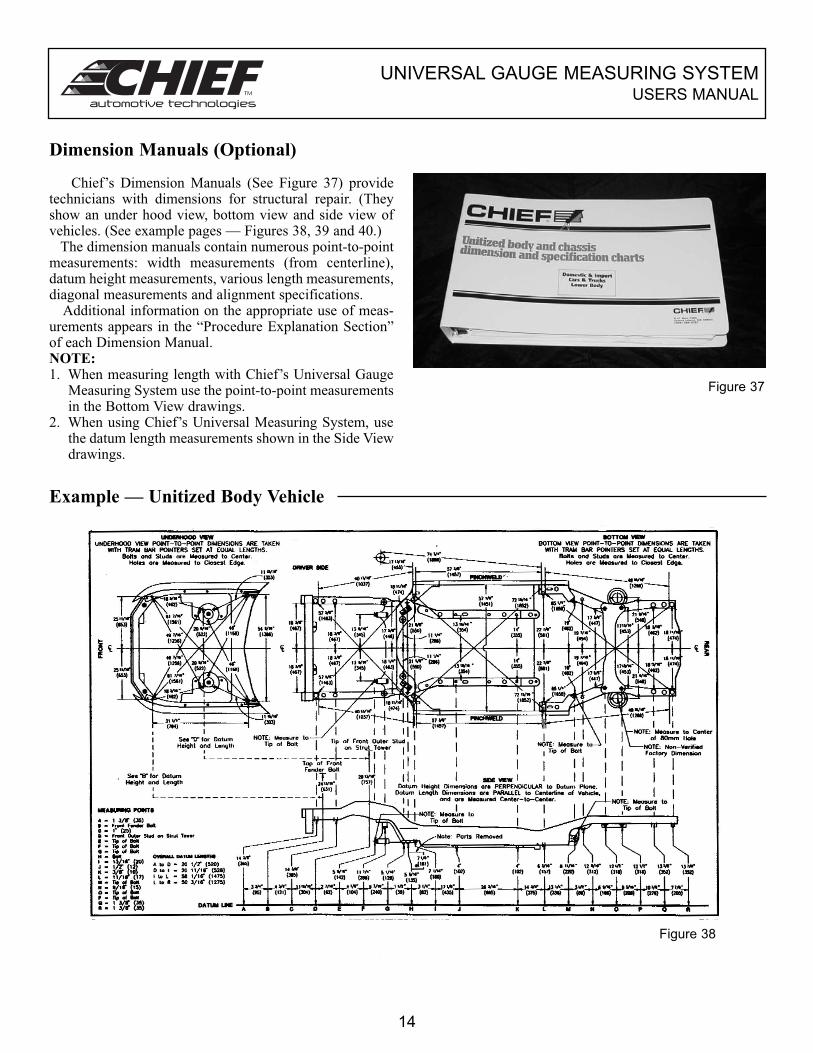
Dimension Manuals (Optional)
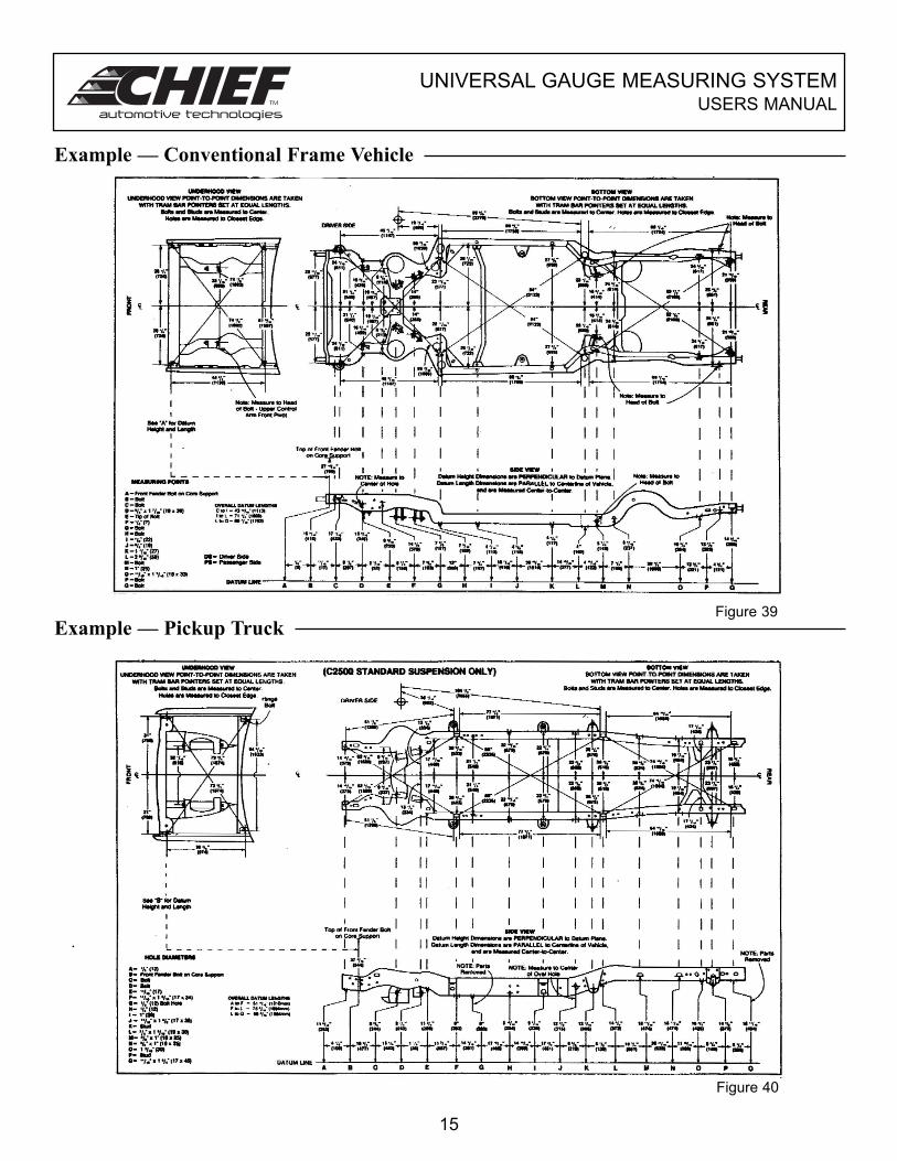
Chief’s Dimension Manuals (See Figure 37) providetechnicians with dimensions for structural repair. (Theyshow an under hood view, bottom view and side view ofvehicles. (See example pages — Figures 38, 39 and 40.)
The dimension manuals contain numerous point-to-pointmeasurements: width measurements (from centerline),datum height measurements, various length measurements,diagonal measurements and alignment specifications.
Additional information on the appropriate use of meas-urements appears in the “Procedure Explanation Section”of each Dimension Manual.NOTE: 1. When measuring length with Chief’s Universal Gauge
Measuring System use the point-to-point measurementsin the Bottom View drawings.
2. When using Chief’s Universal Measuring System, usethe datum length measurements shown in the Side Viewdrawings.
Figure 37
Example — Unitized Body Vehicle
14
Figure 38
UNIVERSAL GAUGE MEASURING SYSTEMUSERS MANUAL
Example — Conventional Frame Vehicle
Example — Pickup TruckFigure 39
Figure 40
15
UNIVERSAL GAUGE MEASURING SYSTEMUSERS MANUAL
16
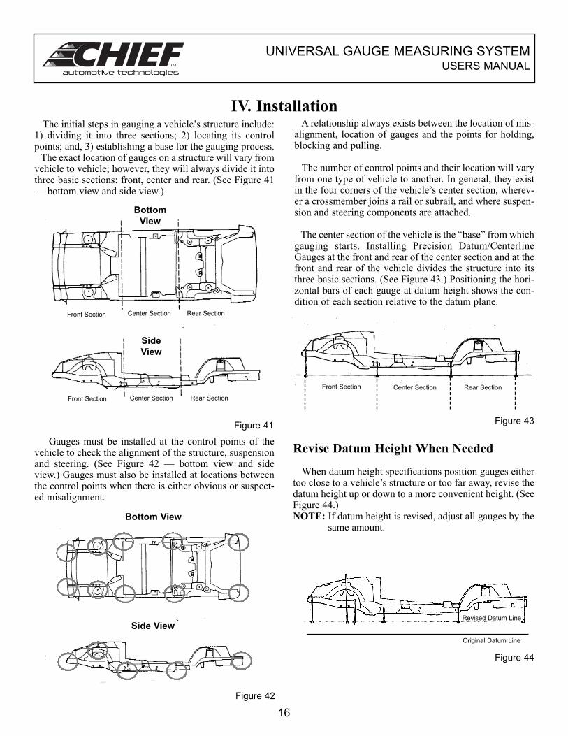
IV. InstallationThe initial steps in gauging a vehicle’s structure include:
1) dividing it into three sections; 2) locating its controlpoints; and, 3) establishing a base for the gauging process.
The exact location of gauges on a structure will vary fromvehicle to vehicle; however, they will always divide it intothree basic sections: front, center and rear. (See Figure 41— bottom view and side view.)
A relationship always exists between the location of mis-alignment, location of gauges and the points for holding,blocking and pulling.
The number of control points and their location will varyfrom one type of vehicle to another. In general, they existin the four corners of the vehicle’s center section, wherev-er a crossmember joins a rail or subrail, and where suspen-sion and steering components are attached.
The center section of the vehicle is the “base” from whichgauging starts. Installing Precision Datum/CenterlineGauges at the front and rear of the center section and at thefront and rear of the vehicle divides the structure into itsthree basic sections. (See Figure 43.) Positioning the hori-zontal bars of each gauge at datum height shows the con-dition of each section relative to the datum plane.
Figure 41
Gauges must be installed at the control points of thevehicle to check the alignment of the structure, suspensionand steering. (See Figure 42 — bottom view and sideview.) Gauges must also be installed at locations betweenthe control points when there is either obvious or suspect-ed misalignment.
Figure 42
Figure 43
Revise Datum Height When Needed
When datum height specifications position gauges eithertoo close to a vehicle’s structure or too far away, revise thedatum height up or down to a more convenient height. (SeeFigure 44.)NOTE: If datum height is revised, adjust all gauges by the
same amount.
Figure 44
Front Section Center Section Rear Section
Original Datum Line
Revised Datum Line
Front Section Center Section Rear Section
Front Section Center Section Rear Section
Side
View
Bottom
View
Bottom View
Side View
UNIVERSAL GAUGE MEASURING SYSTEMUSERS MANUAL
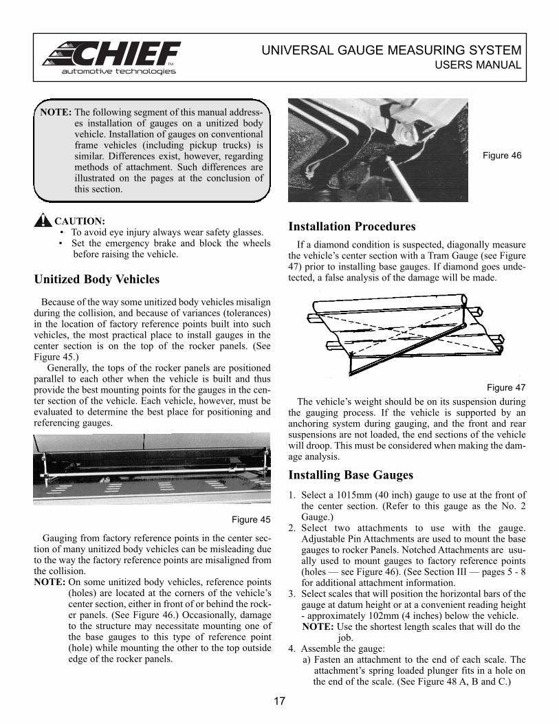
NOTE: The following segment of this manual address-es installation of gauges on a unitized bodyvehicle. Installation of gauges on conventionalframe vehicles (including pickup trucks) issimilar. Differences exist, however, regardingmethods of attachment. Such differences areillustrated on the pages at the conclusion ofthis section.
CAUTION:• To avoid eye injury always wear safety glasses.• Set the emergency brake and block the wheels
before raising the vehicle.
Unitized Body Vehicles
Because of the way some unitized body vehicles misalignduring the collision, and because of variances (tolerances)in the location of factory reference points built into suchvehicles, the most practical place to install gauges in thecenter section is on the top of the rocker panels. (SeeFigure 45.)
Generally, the tops of the rocker panels are positionedparallel to each other when the vehicle is built and thusprovide the best mounting points for the gauges in the cen-ter section of the vehicle. Each vehicle, however, must beevaluated to determine the best place for positioning andreferencing gauges.
Figure 45
Gauging from factory reference points in the center sec-tion of many unitized body vehicles can be misleading dueto the way the factory reference points are misaligned fromthe collision.NOTE: On some unitized body vehicles, reference points
(holes) are located at the corners of the vehicle’scenter section, either in front of or behind the rock-er panels. (See Figure 46.) Occasionally, damageto the structure may necessitate mounting one ofthe base gauges to this type of reference point(hole) while mounting the other to the top outsideedge of the rocker panels.
Figure 46
Installation Procedures
If a diamond condition is suspected, diagonally measurethe vehicle’s center section with a Tram Gauge (see Figure47) prior to installing base gauges. If diamond goes unde-tected, a false analysis of the damage will be made.
Figure 47
The vehicle’s weight should be on its suspension duringthe gauging process. If the vehicle is supported by ananchoring system during gauging, and the front and rearsuspensions are not loaded, the end sections of the vehiclewill droop. This must be considered when making the dam-age analysis.
Installing Base Gauges
1. Select a 1015mm (40 inch) gauge to use at the front ofthe center section. (Refer to this gauge as the No. 2Gauge.)
2. Select two attachments to use with the gauge.Adjustable Pin Attachments are used to mount the basegauges to rocker Panels. Notched Attachments are usu-ally used to mount gauges to factory reference points(holes — see Figure 46). (See Section III — pages 5 - 8for additional attachment information.
3. Select scales that will position the horizontal bars of thegauge at datum height or at a convenient reading height- approximately 102mm (4 inches) below the vehicle.NOTE: Use the shortest length scales that will do the
job.4. Assemble the gauge:
a) Fasten an attachment to the end of each scale. The attachment’s spring loaded plunger fits in a hole onthe end of the scale. (See Figure 48 A, B and C.)
17
UNIVERSAL GAUGE MEASURING SYSTEMUSERS MANUAL
Figure 48
A B C
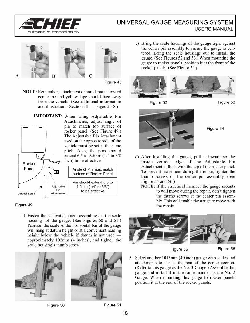
NOTE: Remember, attachments should point towardcenterline and yellow tape should face awayfrom the vehicle. (See additional informationand illustration - Section III — pages 5 - 8.)
IMPORTANT: When using Adjustable PinAttachments, adjust angle ofpin to match top surface ofrocker panel. (See Figure 49.)The Adjustable Pin Attachmentused on the opposite side of thevehicle must be set at the samepitch. Also, the pins shouldextend 6.5 to 9.5mm (1/4 to 3/8inch) to be effective.
Figure 49
Angle of Pin must match
surface of Rocker Panel
Pin should extend 6.5 to
9.5mm (1/4” to 3/8”)
to be effective
b) Fasten the scale/attachment assemblies in the scalehousings of the gauge. (See Figures 50 and 51.)Position the scale so the horizontal bar of the gaugewill hang at datum height or at a convenient readingheight below the vehicle if datum is not used —approximately 102mm (4 inches), and tighten thescale housing’s thumb screw.
Figure 50 Figure 51
c) Bring the scale housings of the gauge tight againstthe center pin assembly to ensure the gauge is cen-tered. Bring the scale housings out to install thegauge. (See Figures 52 and 53.) When mounting thegauge to rocker panels, position it at the front of therocker panels. (See Figure 54.)
Figure 52 Figure 53
Figure 54
d) After installing the gauge, pull it inward so theinside vertical edge of the Adjustable PinAttachment is flush with the top of the rocker panel.To prevent movement during the repair, tighten thethumb screws on the center pin assembly. (SeeFigure 55 and 56.)NOTE: If the structural member the gauge mounts
to will move during the repair, don’t tightenthe thumb screws at the center pin assem-bly. This will enable the gauge to move withthe repair.
Figure 55 Figure 56
5. Select another 1015mm (40 inch) gauge with scales andattachments to use at the rear of the center section.(Refer to this gauge as the No. 3 Gauge.) Assemble thisgauge and install it in the same manner as the No. 2Gauge. When mounting this gauge to rocker panelsposition it at the rear of the rocker panels.
18
Rocker
Panel
Adjustable
Pin
AttachmentVertical Scale
UNIVERSAL GAUGE MEASURING SYSTEMUSERS MANUAL
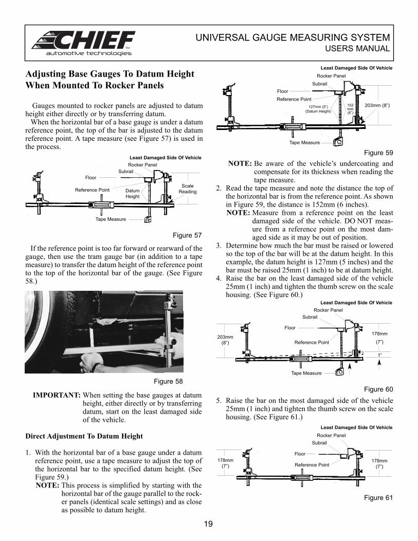
Adjusting Base Gauges To Datum Height
When Mounted To Rocker Panels
Gauges mounted to rocker panels are adjusted to datumheight either directly or by transferring datum.
When the horizontal bar of a base gauge is under a datumreference point, the top of the bar is adjusted to the datumreference point. A tape measure (see Figure 57) is used inthe process.
Figure 57
If the reference point is too far forward or rearward of thegauge, then use the tram gauge bar (in addition to a tapemeasure) to transfer the datum height of the reference pointto the top of the horizontal bar of the gauge. (See Figure58.)
IMPORTANT: When setting the base gauges at datumheight, either directly or by transferringdatum, start on the least damaged sideof the vehicle.
Direct Adjustment To Datum Height
1. With the horizontal bar of a base gauge under a datumreference point, use a tape measure to adjust the top ofthe horizontal bar to the specified datum height. (SeeFigure 59.) NOTE: This process is simplified by starting with the
horizontal bar of the gauge parallel to the rock-er panels (identical scale settings) and as closeas possible to datum height.
Figure 59
NOTE: Be aware of the vehicle’s undercoating andcompensate for its thickness when reading thetape measure.
2. Read the tape measure and note the distance the top ofthe horizontal bar is from the reference point. As shownin Figure 59, the distance is 152mm (6 inches).NOTE: Measure from a reference point on the least
damaged side of the vehicle. DO NOT meas-ure from a reference point on the most dam-aged side as it may be out of position.
3. Determine how much the bar must be raised or loweredso the top of the bar will be at the datum height. In thisexample, the datum height is 127mm (5 inches) and thebar must be raised 25mm (1 inch) to be at datum height.
4. Raise the bar on the least damaged side of the vehicle25mm (1 inch) and tighten the thumb screw on the scalehousing. (See Figure 60.)
Figure 60
5. Raise the bar on the most damaged side of the vehicle25mm (1 inch) and tighten the thumb screw on the scalehousing. (See Figure 61.)
Figure 61
19
Figure 58
Floor
Reference Point Datum
Height
Rocker Panel
Subrail
Scale
Reading
Tape Measure
Floor
Reference Point
Least Damaged Side Of Vehicle
127mm (5”)
(Datum Height)
Rocker Panel
Subrail
203mm (8”)152mm (6”)
Tape Measure
203mm
(8”)
178mm
(7”)
1”
Floor
Least Damaged Side Of Vehicle
Rocker Panel
Subrail
Reference Point
Tape Measure
Least Damaged Side Of Vehicle
Rocker Panel
Subrail
Floor
Reference Point178mm
(7”)
178mm
(7”)
Least Damaged Side Of Vehicle
UNIVERSAL GAUGE MEASURING SYSTEMUSERS MANUAL
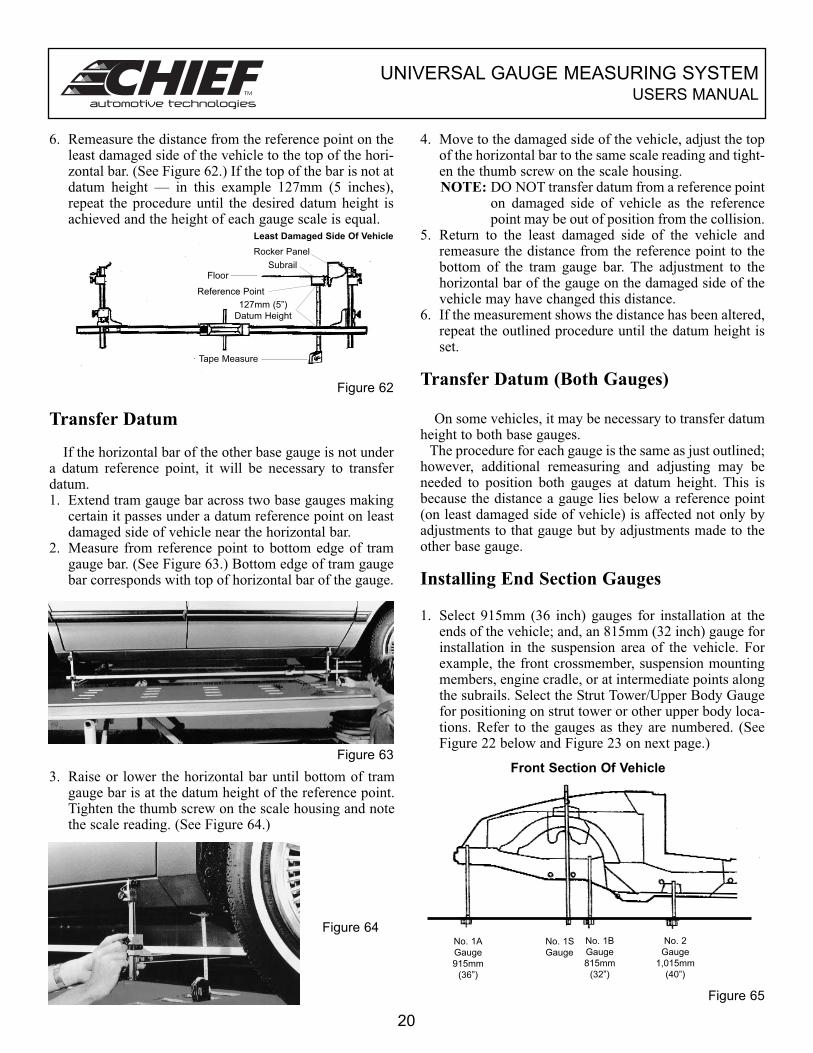
6. Remeasure the distance from the reference point on theleast damaged side of the vehicle to the top of the hori-zontal bar. (See Figure 62.) If the top of the bar is not atdatum height — in this example 127mm (5 inches),repeat the procedure until the desired datum height isachieved and the height of each gauge scale is equal.
Figure 62
Transfer Datum
If the horizontal bar of the other base gauge is not undera datum reference point, it will be necessary to transferdatum. 1. Extend tram gauge bar across two base gauges making
certain it passes under a datum reference point on leastdamaged side of vehicle near the horizontal bar.
2. Measure from reference point to bottom edge of tramgauge bar. (See Figure 63.) Bottom edge of tram gaugebar corresponds with top of horizontal bar of the gauge.
Figure 63
3. Raise or lower the horizontal bar until bottom of tramgauge bar is at the datum height of the reference point.Tighten the thumb screw on the scale housing and notethe scale reading. (See Figure 64.)
Figure 64
4. Move to the damaged side of the vehicle, adjust the topof the horizontal bar to the same scale reading and tight-en the thumb screw on the scale housing.NOTE: DO NOT transfer datum from a reference point
on damaged side of vehicle as the referencepoint may be out of position from the collision.
5. Return to the least damaged side of the vehicle andremeasure the distance from the reference point to thebottom of the tram gauge bar. The adjustment to thehorizontal bar of the gauge on the damaged side of thevehicle may have changed this distance.
6. If the measurement shows the distance has been altered,repeat the outlined procedure until the datum height isset.
Transfer Datum (Both Gauges)
On some vehicles, it may be necessary to transfer datumheight to both base gauges.
The procedure for each gauge is the same as just outlined;however, additional remeasuring and adjusting may beneeded to position both gauges at datum height. This isbecause the distance a gauge lies below a reference point(on least damaged side of vehicle) is affected not only byadjustments to that gauge but by adjustments made to theother base gauge.
Installing End Section Gauges
1. Select 915mm (36 inch) gauges for installation at theends of the vehicle; and, an 815mm (32 inch) gauge forinstallation in the suspension area of the vehicle. Forexample, the front crossmember, suspension mountingmembers, engine cradle, or at intermediate points alongthe subrails. Select the Strut Tower/Upper Body Gaugefor positioning on strut tower or other upper body loca-tions. Refer to the gauges as they are numbered. (SeeFigure 22 below and Figure 23 on next page.)
Figure 65
20
No. 1A
Gauge
915mm
(36”)
No. 1S
Gauge
No. 1B
Gauge
815mm
(32”)
No. 2
Gauge
1,015mm
(40”)
Front Section Of Vehicle
Least Damaged Side Of Vehicle
Rocker Panel
SubrailFloor
Reference Point
127mm (5”)
Datum Height
Tape Measure
UNIVERSAL GAUGE MEASURING SYSTEMUSERS MANUAL
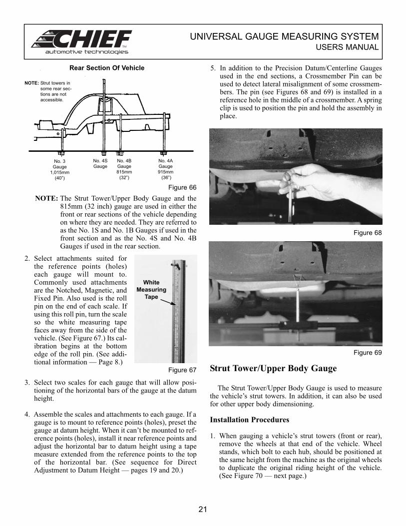
Figure 66
NOTE: The Strut Tower/Upper Body Gauge and the815mm (32 inch) gauge are used in either thefront or rear sections of the vehicle dependingon where they are needed. They are referred toas the No. 1S and No. 1B Gauges if used in thefront section and as the No. 4S and No. 4BGauges if used in the rear section.
2. Select attachments suited forthe reference points (holes)each gauge will mount to.Commonly used attachmentsare the Notched, Magnetic, andFixed Pin. Also used is the rollpin on the end of each scale. Ifusing this roll pin, turn the scaleso the white measuring tapefaces away from the side of thevehicle. (See Figure 67.) Its cal-ibration begins at the bottomedge of the roll pin. (See addi-tional information — Page 8.)
Figure 67
3. Select two scales for each gauge that will allow posi-tioning of the horizontal bars of the gauge at the datumheight.
4. Assemble the scales and attachments to each gauge. If agauge is to mount to reference points (holes), preset thegauge at datum height. When it can’t be mounted to ref-erence points (holes), install it near reference points andadjust the horizontal bar to datum height using a tapemeasure extended from the reference points to the topof the horizontal bar. (See sequence for DirectAdjustment to Datum Height — pages 19 and 20.)
5. In addition to the Precision Datum/Centerline Gaugesused in the end sections, a Crossmember Pin can beused to detect lateral misalignment of some crossmem-bers. The pin (see Figures 68 and 69) is installed in areference hole in the middle of a crossmember. A springclip is used to position the pin and hold the assembly inplace.
Figure 68
Figure 69
Strut Tower/Upper Body Gauge
The Strut Tower/Upper Body Gauge is used to measurethe vehicle’s strut towers. In addition, it can also be usedfor other upper body dimensioning.
Installation Procedures
1. When gauging a vehicle’s strut towers (front or rear),remove the wheels at that end of the vehicle. Wheelstands, which bolt to each hub, should be positioned atthe same height from the machine as the original wheelsto duplicate the original riding height of the vehicle.(See Figure 70 — next page.)
21
NOTE: Strut towers in
some rear sec-
tions are not
accessible.
Rear Section Of Vehicle
No. 4A
Gauge
915mm
(36”)
No. 3
Gauge
1,015mm
(40”)
No. 4S
Gauge
No. 4B
Gauge
815mm
(32”)
White
Measuring
Tape
UNIVERSAL GAUGE MEASURING SYSTEMUSERS MANUAL
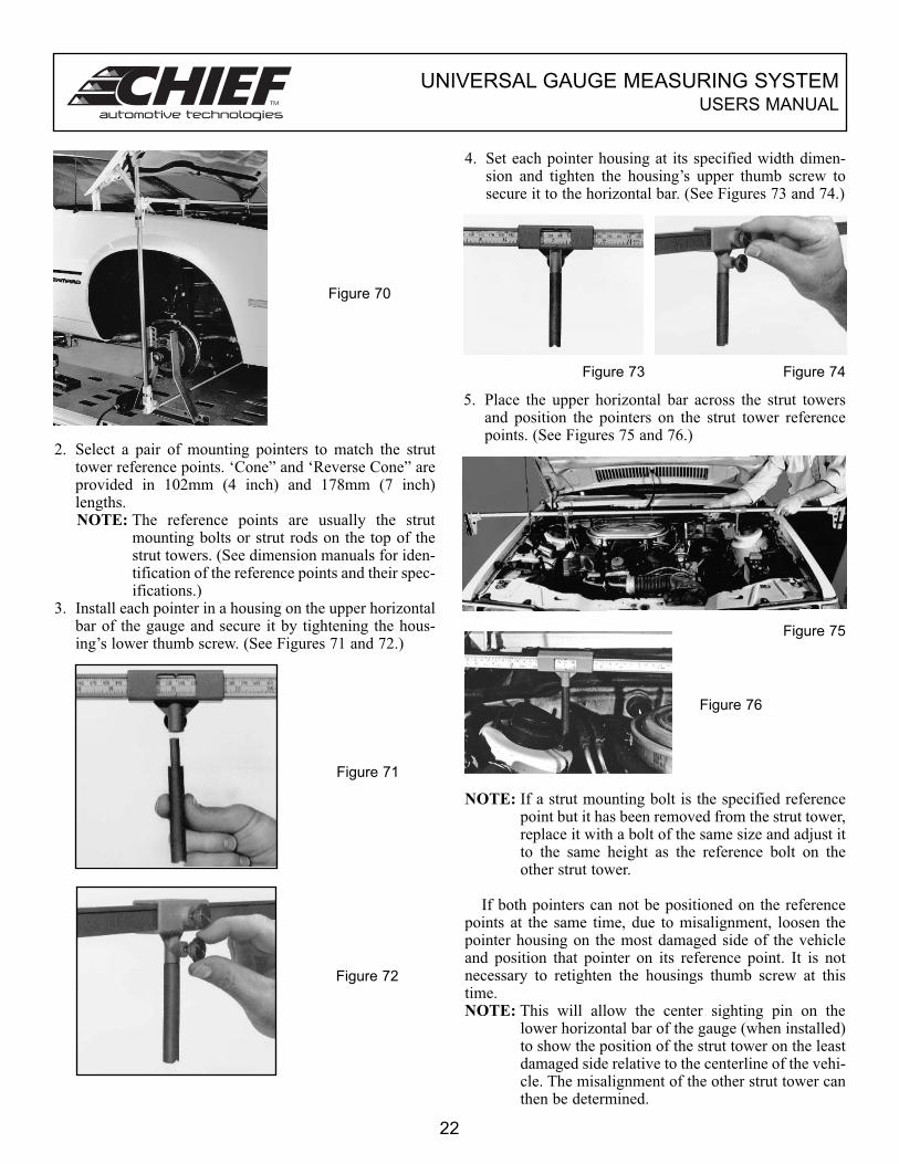
Figure 70
2. Select a pair of mounting pointers to match the struttower reference points. ‘Cone” and ‘Reverse Cone” areprovided in 102mm (4 inch) and 178mm (7 inch)lengths.NOTE: The reference points are usually the strut
mounting bolts or strut rods on the top of thestrut towers. (See dimension manuals for iden-tification of the reference points and their spec-ifications.)
3. Install each pointer in a housing on the upper horizontalbar of the gauge and secure it by tightening the hous-ing’s lower thumb screw. (See Figures 71 and 72.)
Figure 71
Figure 72
22
4. Set each pointer housing at its specified width dimen-sion and tighten the housing’s upper thumb screw tosecure it to the horizontal bar. (See Figures 73 and 74.)
Figure 73 Figure 74
5. Place the upper horizontal bar across the strut towersand position the pointers on the strut tower referencepoints. (See Figures 75 and 76.)
Figure 75
Figure 76
NOTE: If a strut mounting bolt is the specified referencepoint but it has been removed from the strut tower,replace it with a bolt of the same size and adjust itto the same height as the reference bolt on theother strut tower.
If both pointers can not be positioned on the referencepoints at the same time, due to misalignment, loosen thepointer housing on the most damaged side of the vehicleand position that pointer on its reference point. It is notnecessary to retighten the housings thumb screw at thistime. NOTE: This will allow the center sighting pin on the
lower horizontal bar of the gauge (when installed)to show the position of the strut tower on the leastdamaged side relative to the centerline of the vehi-cle. The misalignment of the other strut tower canthen be determined.
UNIVERSAL GAUGE MEASURING SYSTEMUSERS MANUAL
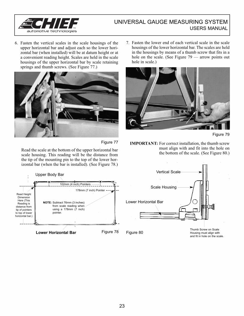
6. Fasten the vertical scales in the scale housings of theupper horizontal bar and adjust each so the lower hori-zontal bar (when installed) will be at datum height or ata convenient reading height. Scales are held in the scalehousings of the upper horizontal bar by scale retainingsprings and thumb screws. (See Figure 77.)
7. Fasten the lower end of each vertical scale in the scalehousings of the lower horizontal bar. The scales are heldin the housings by means of a thumb screw that fits in ahole on the scale. (See Figure 79 — arrow points outhole in scale.)
Read the scale at the bottom of the upper horizontal barscale housing. This reading will be the distance fromthe tip of the mounting pin to the top of the lower hor-izontal bar (when the bar is installed). (See Figure 78.)
Figure 77
Figure 79
IMPORTANT: For correct installation, the thumb screwmust align with and fit into the hole onthe bottom of the scale. (See Figure 80.)
Figure 80
23
Thumb Screw on Scale
Housing must align with
and fit in hole on the scale.
Vertical Scale
Scale Housing
Lower Horizontal Bar
Upper Body Bar
102mm (4 inch) Pointers
Lower Horizontal Bar
NOTE: Subtract 76mm (3 inches)
from scale reading when
using a 178mm (7 inch)
pointer.
178mm (7 inch) Pointer
Read Height
Dimension
Here (This
Reading is
distance from
tip of pointers
to top of lower
horizontal bar.)
Figure 78
UNIVERSAL GAUGE MEASURING SYSTEMUSERS MANUAL
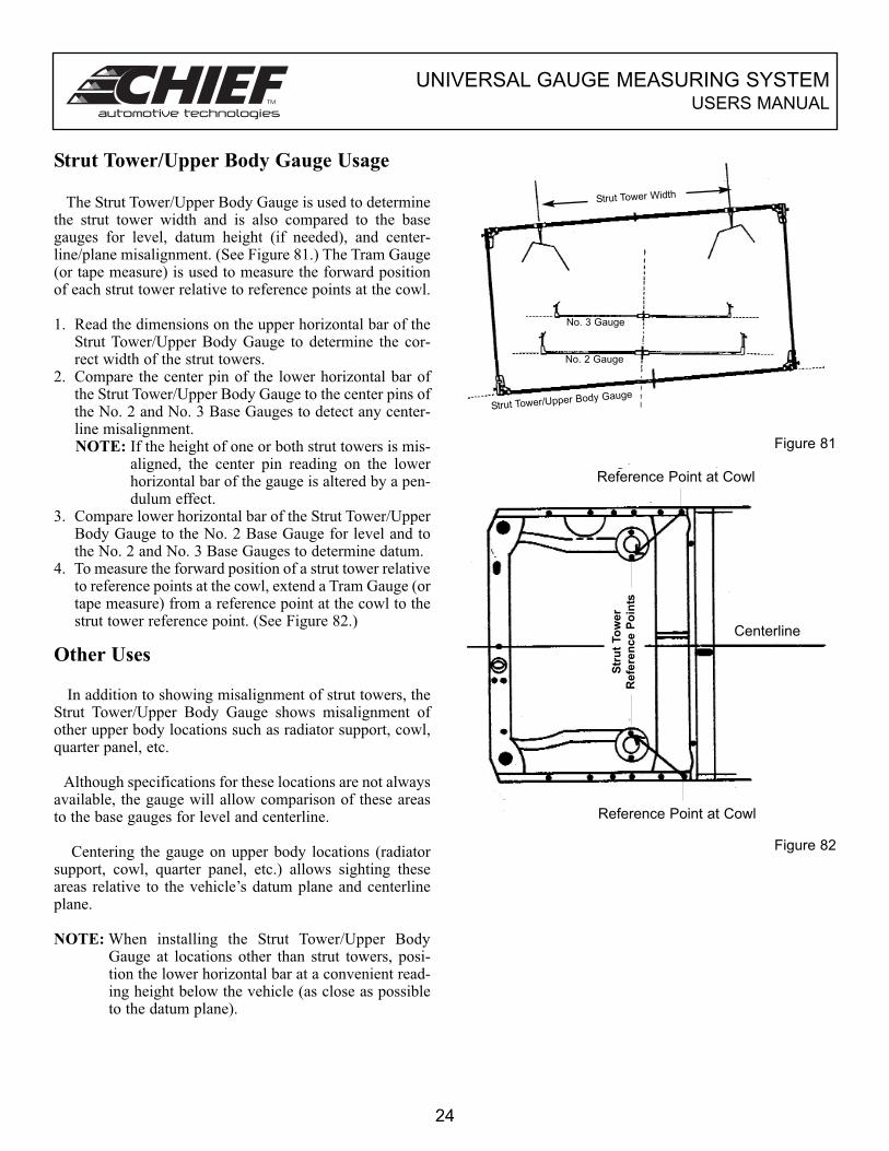
Strut Tower/Upper Body Gauge Usage
The Strut Tower/Upper Body Gauge is used to determinethe strut tower width and is also compared to the basegauges for level, datum height (if needed), and center-line/plane misalignment. (See Figure 81.) The Tram Gauge(or tape measure) is used to measure the forward positionof each strut tower relative to reference points at the cowl.
1. Read the dimensions on the upper horizontal bar of theStrut Tower/Upper Body Gauge to determine the cor-rect width of the strut towers.
2. Compare the center pin of the lower horizontal bar ofthe Strut Tower/Upper Body Gauge to the center pins ofthe No. 2 and No. 3 Base Gauges to detect any center-line misalignment.NOTE: If the height of one or both strut towers is mis-
aligned, the center pin reading on the lowerhorizontal bar of the gauge is altered by a pen-dulum effect.
3. Compare lower horizontal bar of the Strut Tower/UpperBody Gauge to the No. 2 Base Gauge for level and tothe No. 2 and No. 3 Base Gauges to determine datum.
4. To measure the forward position of a strut tower relativeto reference points at the cowl, extend a Tram Gauge (ortape measure) from a reference point at the cowl to thestrut tower reference point. (See Figure 82.)
Other Uses
In addition to showing misalignment of strut towers, theStrut Tower/Upper Body Gauge shows misalignment ofother upper body locations such as radiator support, cowl,quarter panel, etc.
Although specifications for these locations are not alwaysavailable, the gauge will allow comparison of these areasto the base gauges for level and centerline.
Centering the gauge on upper body locations (radiatorsupport, cowl, quarter panel, etc.) allows sighting theseareas relative to the vehicle’s datum plane and centerlineplane.
NOTE: When installing the Strut Tower/Upper BodyGauge at locations other than strut towers, posi-tion the lower horizontal bar at a convenient read-ing height below the vehicle (as close as possibleto the datum plane).
Figure 81
Figure 82
24
Reference Point at Cowl
Reference Point at Cowl
Str
ut
To
wer
Refe
ren
ce P
oin
ts
Strut Tower Width
Strut Tower/Upper Body Gauge
No. 3 Gauge
No. 2 Gauge
Centerline
UNIVERSAL GAUGE MEASURING SYSTEMUSERS MANUAL
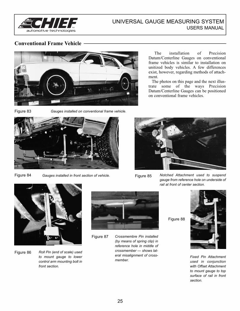
Conventional Frame Vehicle
The installation of PrecisionDatum/Centerline Gauges on conventionalframe vehicles is similar to installation onunitized body vehicles. A few differencesexist, however, regarding methods of attach-ment.
The photos on this page and the next illus-trate some of the ways PrecisionDatum/Centerline Gauges can be positionedon conventional frame vehicles.
Figure 83 Gauges installed on conventional frame vehicle.
Figure 84 Figure 85Gauges installed in front section of vehicle. Notched Attachment used to suspendgauge from reference hole on underside ofrail at front of center section.
Figure 86
Figure 87
Figure 88
Roll Pin (end of scale) usedto mount gauge to lowercontrol arm mounting bolt infront section.
Crossmembre Pin installed(by means of spring clip) inreference hole in middle ofcrossmember — shows lat-eral misalignment of cross-member.
Fixed Pin Attachmentused in conjunctionwith Offset Attachmentto mount gauge to topsurface of rail in frontsection.
25
UNIVERSAL GAUGE MEASURING SYSTEMUSERS MANUAL
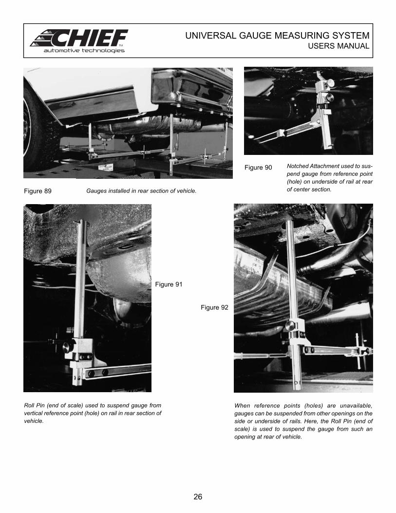
Figure 89
Figure 90
Gauges installed in rear section of vehicle.
Notched Attachment used to sus-pend gauge from reference point(hole) on underside of rail at rearof center section.
Figure 91
Figure 92
Roll Pin (end of scale) used to suspend gauge fromvertical reference point (hole) on rail in rear section ofvehicle.
When reference points (holes) are unavailable,gauges can be suspended from other openings on theside or underside of rails. Here, the Roll Pin (end ofscale) is used to suspend the gauge from such anopening at rear of vehicle.
26
UNIVERSAL GAUGE MEASURING SYSTEMUSERS MANUAL
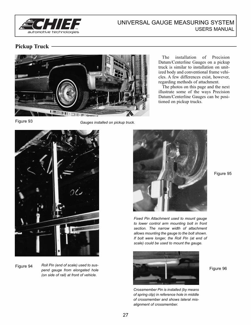
Pickup Truck
The installation of PrecisionDatum/Centerline Gauges on a pickuptruck is similar to installation on unit-ized body and conventional frame vehi-cles. A few differences exist, however,regarding methods of attachment.
The photos on this page and the nextillustrate some of the ways PrecisionDatum/Centerline Gauges can be posi-tioned on pickup trucks.
Figure 93 Gauges installed on pickup truck.
Figure 94 Roll Pin (end of scale) used to sus-pend gauge from elongated hole(on side of rail) at front of vehicle.
Figure 95
Fixed Pin Attachment used to mount gaugeto lower control arm mounting bolt in frontsection. The narrow width of attachmentallows mounting the gauge to the bolt shown.If bolt were longer, the Roll Pin (at end ofscale) could be used to mount the gauge.
Crossmember Pin is installed (by meansof spring clip) in reference hole in middleof crossmember and shows lateral mis-alignment of crossmember.
Figure 96
27
UNIVERSAL GAUGE MEASURING SYSTEMUSERS MANUAL
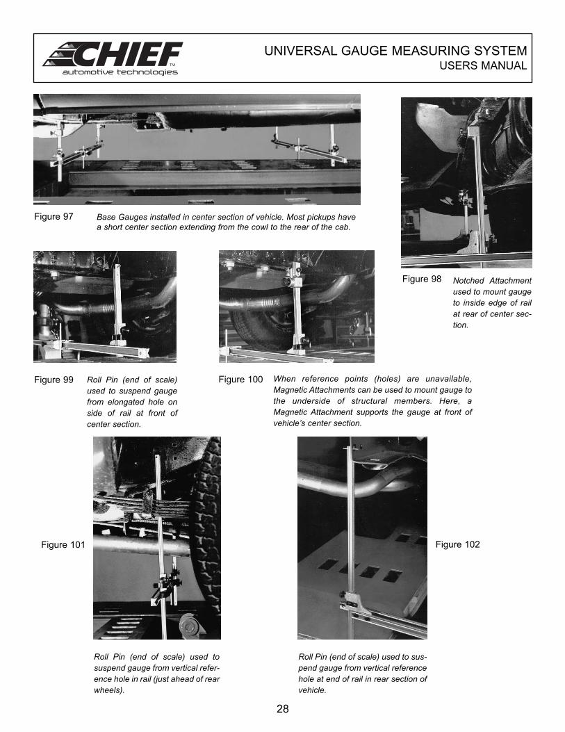
Figure 97 Base Gauges installed in center section of vehicle. Most pickups havea short center section extending from the cowl to the rear of the cab.
Figure 98 Notched Attachmentused to mount gaugeto inside edge of railat rear of center sec-tion.
Figure 99 Figure 100Roll Pin (end of scale)used to suspend gaugefrom elongated hole onside of rail at front ofcenter section.
When reference points (holes) are unavailable,Magnetic Attachments can be used to mount gauge tothe underside of structural members. Here, aMagnetic Attachment supports the gauge at front ofvehicle’s center section.
Figure 101 Figure 102
Roll Pin (end of scale) used tosuspend gauge from vertical refer-ence hole in rail (just ahead of rearwheels).
Roll Pin (end of scale) used to sus-pend gauge from vertical referencehole at end of rail in rear section ofvehicle.
28
UNIVERSAL GAUGE MEASURING SYSTEMUSERS MANUAL
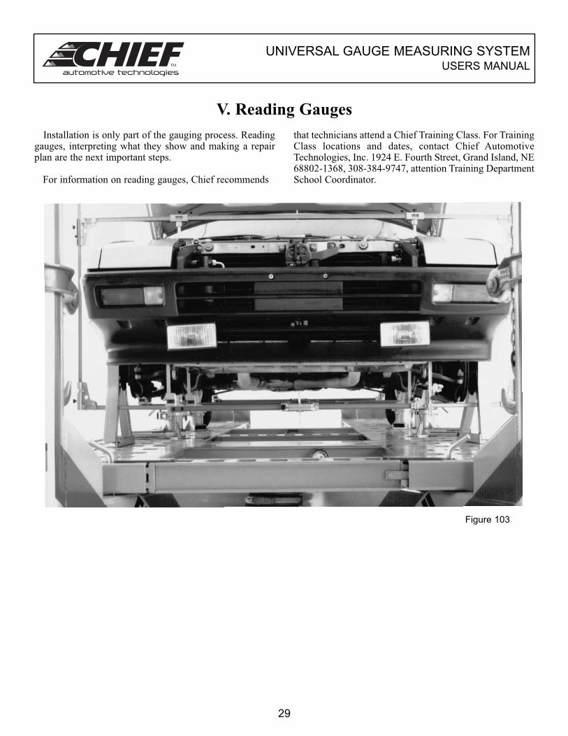
V. Reading Gauges
Installation is only part of the gauging process. Readinggauges, interpreting what they show and making a repairplan are the next important steps.
For information on reading gauges, Chief recommends
that technicians attend a Chief Training Class. For TrainingClass locations and dates, contact Chief AutomotiveTechnologies, Inc. 1924 E. Fourth Street, Grand Island, NE68802-1368, 308-384-9747, attention Training DepartmentSchool Coordinator.
Figure 103
29
UNIVERSAL GAUGE MEASURING SYSTEMUSERS MANUAL
VI. Maintenance Tips
The equipment in the Universal Gauge Measuring Systemis easy to use, features measuring capabilities and isdurable. Like any precision instruments; however, thecomponents of the system should be kept clean and occa-sionally the calibration should be checked.
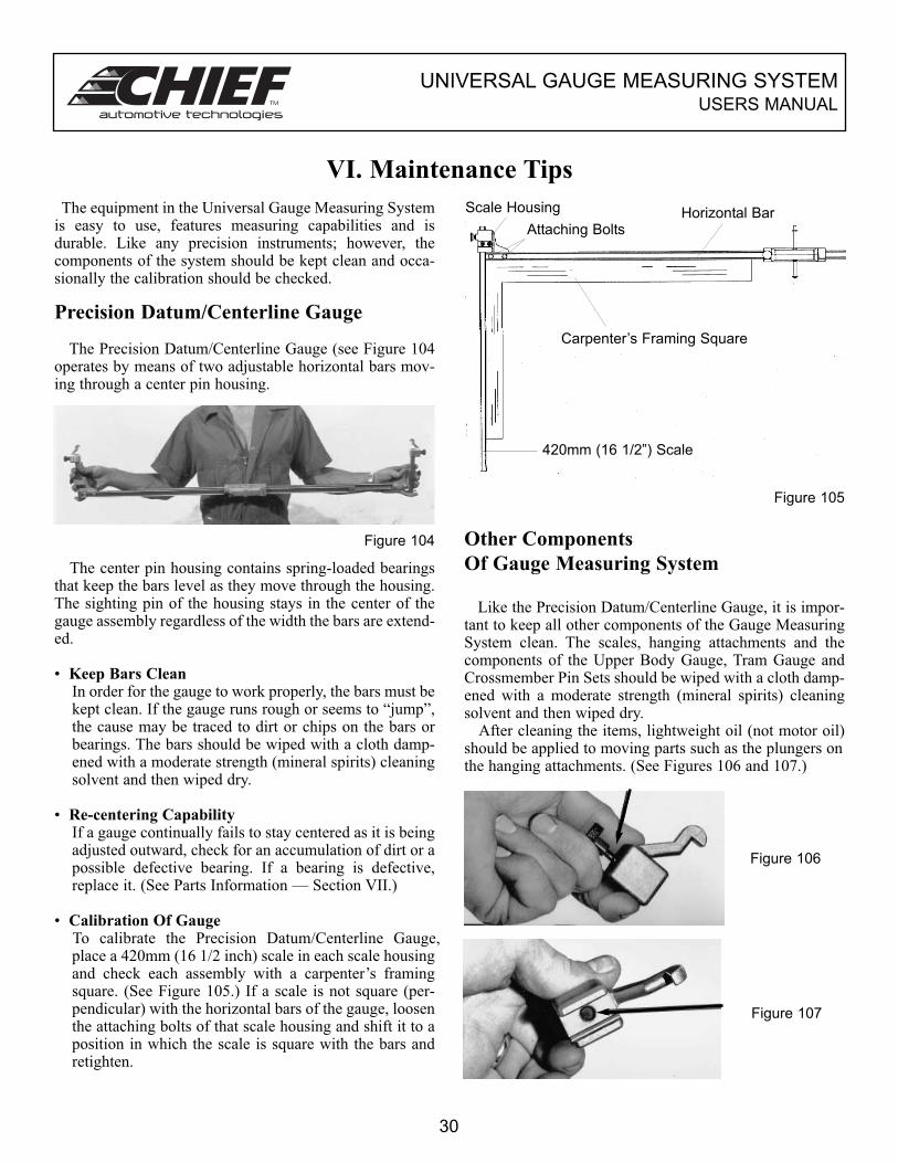
Precision Datum/Centerline Gauge
The Precision Datum/Centerline Gauge (see Figure 104operates by means of two adjustable horizontal bars mov-ing through a center pin housing.
Figure 104
The center pin housing contains spring-loaded bearingsthat keep the bars level as they move through the housing.The sighting pin of the housing stays in the center of thegauge assembly regardless of the width the bars are extend-ed.
• Keep Bars CleanIn order for the gauge to work properly, the bars must bekept clean. If the gauge runs rough or seems to “jump”,the cause may be traced to dirt or chips on the bars orbearings. The bars should be wiped with a cloth damp-ened with a moderate strength (mineral spirits) cleaningsolvent and then wiped dry.
• Re-centering CapabilityIf a gauge continually fails to stay centered as it is beingadjusted outward, check for an accumulation of dirt or apossible defective bearing. If a bearing is defective,replace it. (See Parts Information — Section VII.)
• Calibration Of GaugeTo calibrate the Precision Datum/Centerline Gauge, place a 420mm (16 1/2 inch) scale in each scale housingand check each assembly with a carpenter’s framingsquare. (See Figure 105.) If a scale is not square (per-pendicular) with the horizontal bars of the gauge, loosenthe attaching bolts of that scale housing and shift it to aposition in which the scale is square with the bars andretighten.
Figure 105
Other Components
Of Gauge Measuring System
Like the Precision Datum/Centerline Gauge, it is impor-tant to keep all other components of the Gauge MeasuringSystem clean. The scales, hanging attachments and thecomponents of the Upper Body Gauge, Tram Gauge andCrossmember Pin Sets should be wiped with a cloth damp-ened with a moderate strength (mineral spirits) cleaningsolvent and then wiped dry.
After cleaning the items, lightweight oil (not motor oil)should be applied to moving parts such as the plungers onthe hanging attachments. (See Figures 106 and 107.)
Figure 106
Figure 107
30
Carpenter’s Framing Square
Scale Housing
Attaching BoltsHorizontal Bar
420mm (16 1/2”) Scale
UNIVERSAL GAUGE MEASURING SYSTEMUSERS MANUAL
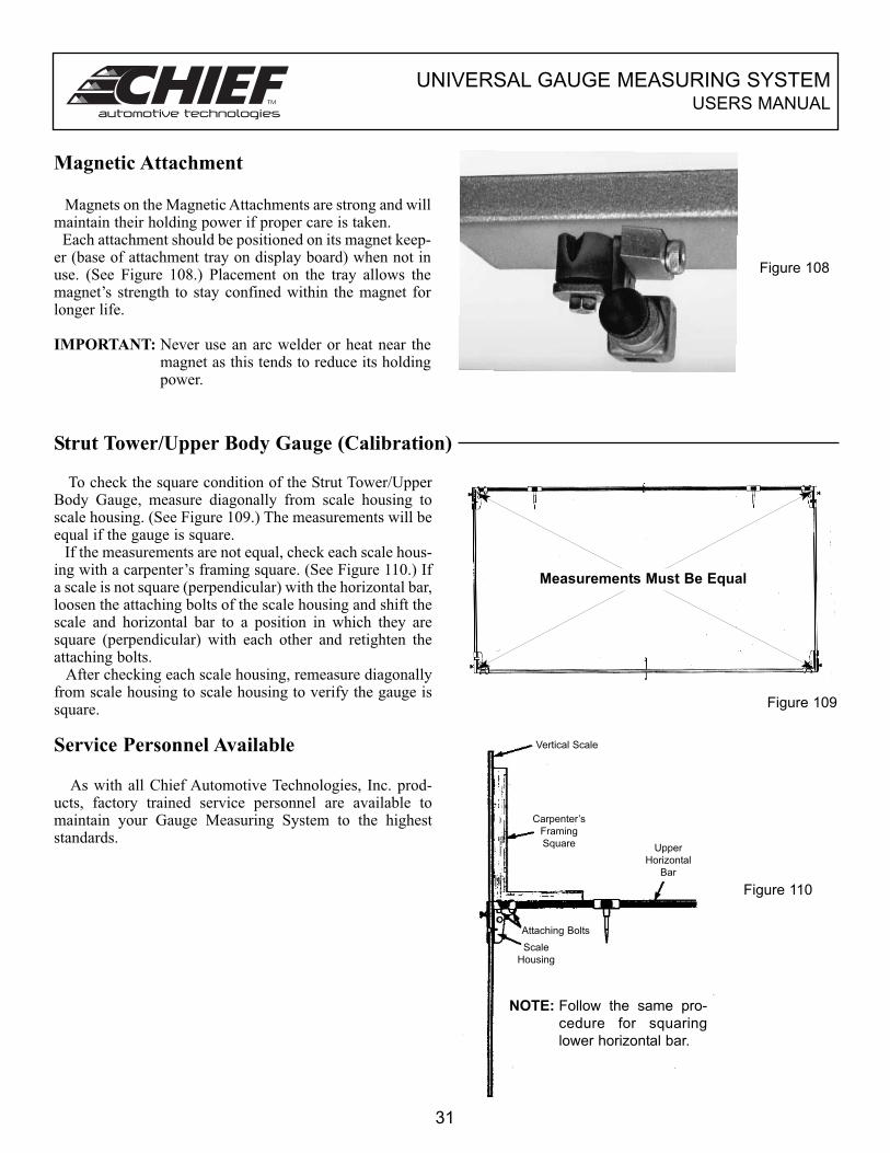
Magnetic Attachment
Magnets on the Magnetic Attachments are strong and willmaintain their holding power if proper care is taken.
Each attachment should be positioned on its magnet keep-er (base of attachment tray on display board) when not inuse. (See Figure 108.) Placement on the tray allows themagnet’s strength to stay confined within the magnet forlonger life.
IMPORTANT: Never use an arc welder or heat near themagnet as this tends to reduce its holdingpower.
Figure 108
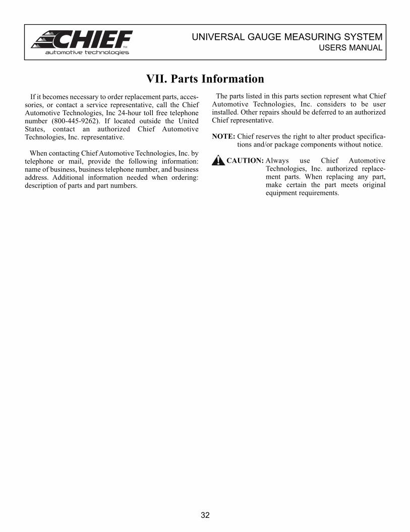
Strut Tower/Upper Body Gauge (Calibration)
To check the square condition of the Strut Tower/UpperBody Gauge, measure diagonally from scale housing toscale housing. (See Figure 109.) The measurements will beequal if the gauge is square.
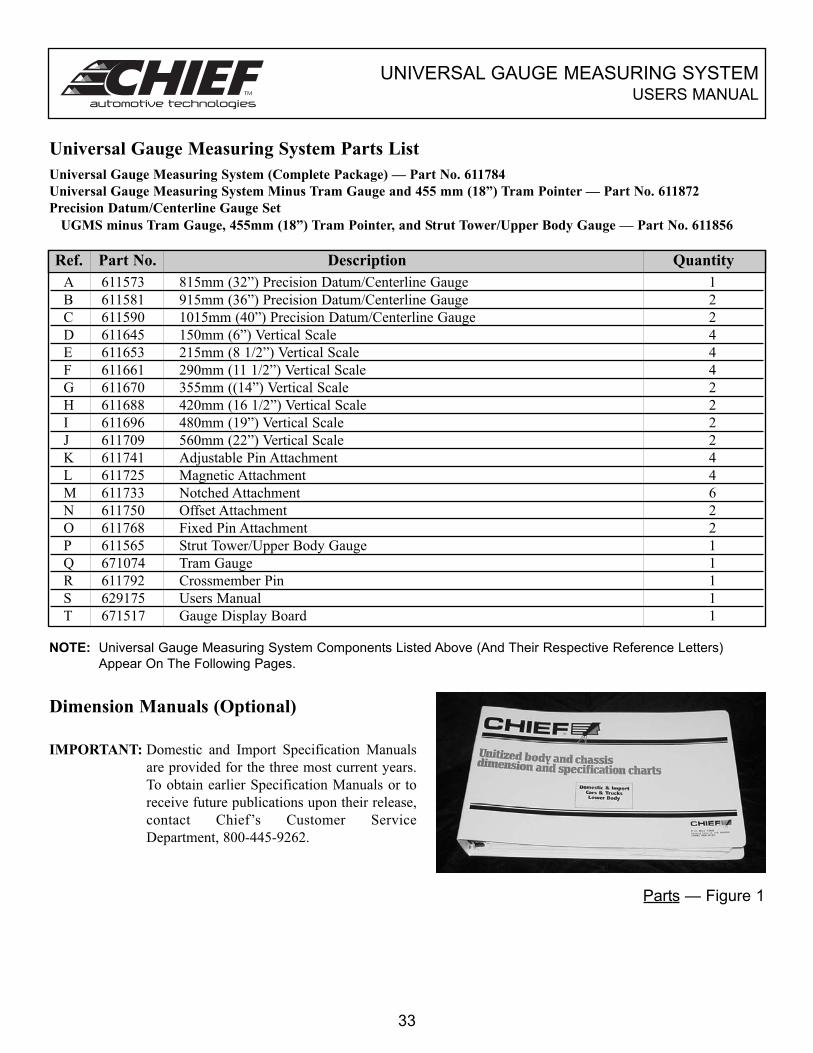
If the measurements are not equal, check each scale hous-ing with a carpenter’s framing square. (See Figure 110.) Ifa scale is not square (perpendicular) with the horizontal bar,loosen the attaching bolts of the scale housing and shift thescale and horizontal bar to a position in which they aresquare (perpendicular) with each other and retighten theattaching bolts.
After checking each scale housing, remeasure diagonallyfrom scale housing to scale housing to verify the gauge issquare.
Service Personnel Available
As with all Chief Automotive Technologies, Inc. prod-ucts, factory trained service personnel are available tomaintain your Gauge Measuring System to the higheststandards.
Figure 109
Figure 110
31
Measurements Must Be Equal
Vertical Scale
Carpenter’s
Framing
Square Upper
Horizontal
Bar
Scale
Housing
Attaching Bolts
NOTE: Follow the same pro-
cedure for squaring
lower horizontal bar.
UNIVERSAL GAUGE MEASURING SYSTEMUSERS MANUAL
VII. Parts Information
If it becomes necessary to order replacement parts, acces-sories, or contact a service representative, call the ChiefAutomotive Technologies, Inc 24-hour toll free telephonenumber (800-445-9262). If located outside the UnitedStates, contact an authorized Chief AutomotiveTechnologies, Inc. representative.
When contacting Chief Automotive Technologies, Inc. bytelephone or mail, provide the following information:name of business, business telephone number, and businessaddress. Additional information needed when ordering:description of parts and part numbers.
The parts listed in this parts section represent what ChiefAutomotive Technologies, Inc. considers to be userinstalled. Other repairs should be deferred to an authorizedChief representative.
NOTE: Chief reserves the right to alter product specifica-tions and/or package components without notice.
CAUTION: Always use Chief AutomotiveTechnologies, Inc. authorized replace-ment parts. When replacing any part,make certain the part meets originalequipment requirements.
32
UNIVERSAL GAUGE MEASURING SYSTEMUSERS MANUAL
A 611573 815mm (32”) Precision Datum/Centerline Gauge 1
B 611581 915mm (36”) Precision Datum/Centerline Gauge 2
C 611590 1015mm (40”) Precision Datum/Centerline Gauge 2
D 611645 150mm (6”) Vertical Scale 4
E 611653 215mm (8 1/2”) Vertical Scale 4
F 611661 290mm (11 1/2”) Vertical Scale 4
G 611670 355mm ((14”) Vertical Scale 2
H 611688 420mm (16 1/2”) Vertical Scale 2
I 611696 480mm (19”) Vertical Scale 2
J 611709 560mm (22”) Vertical Scale 2
K 611741 Adjustable Pin Attachment 4
L 611725 Magnetic Attachment 4
M 611733 Notched Attachment 6
N 611750 Offset Attachment 2
O 611768 Fixed Pin Attachment 2
P 611565 Strut Tower/Upper Body Gauge 1
Q 671074 Tram Gauge 1
R 611792 Crossmember Pin 1
S 629175 Users Manual 1
T 671517 Gauge Display Board 1
Dimension Manuals (Optional)
Universal Gauge Measuring System Parts List
Universal Gauge Measuring System (Complete Package) — Part No. 611784
Universal Gauge Measuring System Minus Tram Gauge and 455 mm (18”) Tram Pointer — Part No. 611872
Precision Datum/Centerline Gauge Set
UGMS minus Tram Gauge, 455mm (18”) Tram Pointer, and Strut Tower/Upper Body Gauge — Part No. 611856
Ref. Part No. Description Quantity
IMPORTANT: Domestic and Import Specification Manuals
are provided for the three most current years.
To obtain earlier Specification Manuals or to
receive future publications upon their release,
contact Chief’s Customer Service
Department, 800-445-9262.
33
Parts — Figure 1
NOTE: Universal Gauge Measuring System Components Listed Above (And Their Respective Reference Letters)
Appear On The Following Pages.
UNIVERSAL GAUGE MEASURING SYSTEMUSERS MANUAL
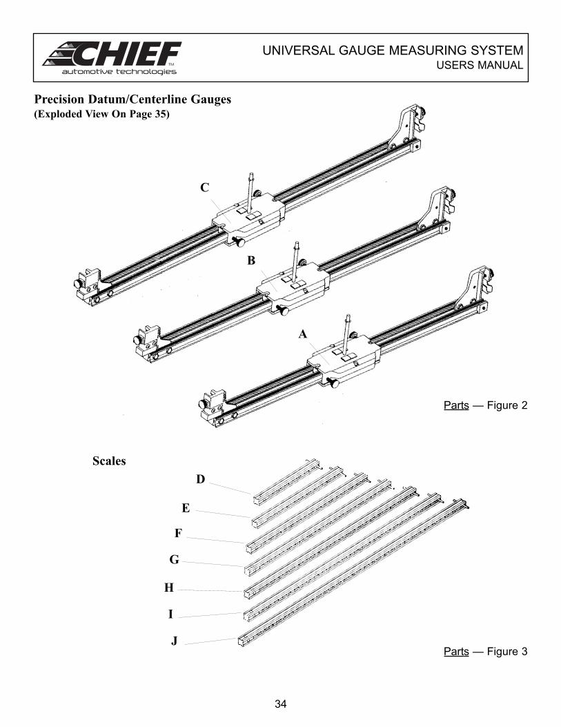
Precision Datum/Centerline Gauges(Exploded View On Page 35)
Scales
34
C
B
Parts — Figure 2
A
D
E
F
G
H
I
JParts — Figure 3
UNIVERSAL GAUGE MEASURING SYSTEMUSERS MANUAL
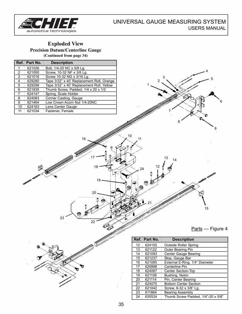
Exploded ViewPrecision Datum/Centerline Gauge
(Continued from page 34)
1 621026 Bolt, 1/4-20 NC x 5/8 Lg.
2 621000 Screw, 10-32 NF x 3/8 Lg.
3 621018 Screw 10-32 NG x 3/16 Lg.
4 629280 Tape 3/32” x 40’ Replacement Roll, Orange
5 629298 Tape 3/32” x 40’ Replacement Roll, Yellow
6 621835 Thumb Screw, Padded, 1/4 x 20 x 1/2
7 624147 Spring, Scale Holder
8 624083 Corner Casting, Gauge
9 621464 Low Crown Acorn Nut 1/4-20NC
10 624163 Lens Center Gauge
11 621034 Fastener, Female
Ref. Part No. Description
12 624155 Outside Roller Spring
13 621122 Outer Bearing Pin
14 621093 Center Gauge Bearing
15 621237 Stop, Gauge Bar
16 621085 External E-Ring, 1/4” Diameter
17 620998 Centerline Pin
18 624067 Center Section-Top
19 621106 Bushing, Nylon
20 621114 Pin, Center Bearing
21 624075 Bottom Center Section
22 621042 Screw, 8-32 x 3/8” Lg.
23 611864 Bearing Assembly
24 635524 Thumb Screw Padded, 1/4”-20 x 5/8”
Ref. Part No. Description
35
Parts — Figure 4
16
12
3
4
5
6
9
7
8
1011
17
18
1314
15
19
20
1224
2223
21
UNIVERSAL GAUGE MEASURING SYSTEMUSERS MANUAL
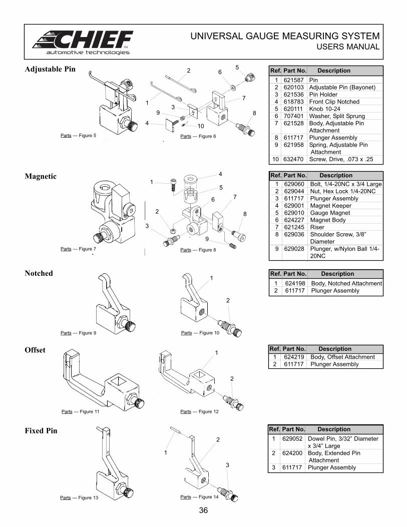
Adjustable Pin
Magnetic
Notched
Offset
Fixed Pin
1 621587 Pin
2 620103 Adjustable Pin (Bayonet)
3 621536 Pin Holder
4 618783 Front Clip Notched
5 620111 Knob 10-24
6 707401 Washer, Split Sprung
7 621528 Body, Adjustable Pin
Attachment
8 611717 Plunger Assembly
9 621958 Spring, Adjustable Pin
Attachment
10 632470 Screw, Drive, .073 x .25
1 629060 Bolt, 1/4-20NC x 3/4 Large
2 629044 Nut, Hex Lock 1/4-20NC
3 611717 Plunger Assembly
4 629001 Magnet Keeper
5 629010 Gauge Magnet
6 624227 Magnet Body
7 621245 Riser
8 629036 Shoulder Screw, 3/8”
Diameter
9 629028 Plunger, w/Nylon Ball 1/4-
20NC
1 624198 Body, Notched Attachment
2 611717 Plunger Assembly
1 624219 Body, Offset Attachment
2 611717 Plunger Assembly
1 629052 Dowel Pin, 3/32” Diameter
x 3/4” Large
2 624200 Body, Extended Pin
Attachment
3 611717 Plunger Assembly
Ref. Part No. Description
Ref. Part No. Description
Ref. Part No. Description
Ref. Part No. Description
Ref. Part No. Description
36
1
25
6
7
8
10
3
4
9
1
4
5
76
8
9
2
3
1
2
1
2
1
2
3
Parts — Figure 13
Parts — Figure 12
Parts — Figure 14
Parts — Figure 11
Parts — Figure 9 Parts — Figure 10
Parts — Figure 7 Parts — Figure 8
Parts — Figure 5 Parts — Figure 6
UNIVERSAL GAUGE MEASURING SYSTEMUSERS MANUAL
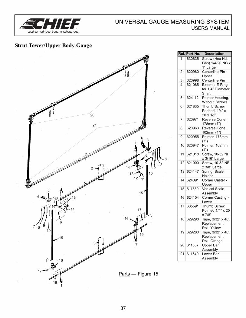
Strut Tower/Upper Body Gauge
1 630635 Screw (Hex Hd.
Cap) 1/4-20 NC x
1” Large
2 620980 Centerline Pin-
Upper
3 620998 Centerline Pin
4 621085 External E-Ring
for 1/4” Diameter
Shaft
5 624112 Pointer Housing,
Without Screws
6 621835 Thumb Screw,
Padded, 1/4” x
20 x 1/2”
7 620971 Reverse Cone,
178mm (7”)
8 620963 Reverse Cone,
102mm (4”)
9 620955 Pointer, 178mm
(7”)
10 620947 Pointer, 102mm
(4”)
11 621018 Screw, 10-32 NF
x 3/16” Large
12 621000 Screw, 10-32 NF
x 3/8” Large
13 624147 Spring, Scale
Holder
14 624091 Corner Caster -
Upper
15 611530 Vertical Scale
Assembly
16 624104 Corner Casting -
Lower
17 635591 Thumb Screw,
Pointed 1/4” x 20
x 7/8”
18 629298 Tape, 3/32” x 40’,
Replacement
Roll, Yellow
19 629280 Tape, 3/32” x 40’,
Replacement
Roll, Orange
20 611557 Upper Bar
Assembly
21 611549 Lower Bar
Assembly
Ref. Part No. Description
37
2 4
7 89
10
17
181
15
16
3
16
17
15
1
5
51
6
7
89
10
14
12 11
6
6
14
13
19
4
13
20
21
11
12
6
Parts — Figure 15
UNIVERSAL GAUGE MEASURING SYSTEMUSERS MANUAL
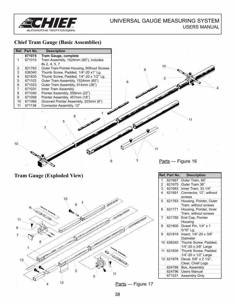
Chief Tram Gauge (Basic Assemblies)
671074 Tram Gauge, complete
1 671015 Tram Assembly, 1524mm (60”), includes
#s 2, 4, 5, 7
2 621763 Outer Tram Pointer Housing, Without Screws
3 636340 Thumb Screw, Padded, 1/4”-20 x1” Lg.
4 621835 Thumb Screw, Padded, 1/4”-20 x 1/2” Lg.
5 671103 Outer Tram Assembly, 1524mm (60”)
6 671023 Outer Tram Assembly, 914mm (36”)
7 671031 Inner Tram Assembly
8 671040 Pointer Assembly, 559mm (22”)
9 671058 Pointer Assembly, 457mm (18”)
10 671066 Grooved Pointer Assembly, 203mm (8”)
11 671138 Connector Assembly, 12”
Ref. Part No. Description
Tram Gauge (Exploded View)1 621667 Outer Tram, 60”
2 621675 Outer Tram 36”
3 621683 Inner Tram, 33 1/4”
4 621691 Connector, 12”, without
screws
5 621763 Housing, Pointer, Outer
Tram, without screws
6 621771 Housing, Pointer, Inner
Tram, without screws
7 621780 End Cap, Pointer
Housing
8 621800 Dowel Pin, 1/4” x 1
5/16” Lg.
9 621819 Insert, 1/4”-20 x 3/8”
Diameter
10 636340 Thumb Screw, Padded,
1/4”-20 x 3/8” Large
11 621835 Thumb Screw, Padded
1/4”-20 x 1/2” Large
12 621878 Decal, 5/8” x 2 1/2”,
Clear, Chief Logo
624788 Box, Assembly
624796 Users Manual
671031 Assembly Only
Ref. Part No. Description
38
10
7
5
81
9
810
11
6
11
2
11
6
7
39
10
12
4 12
2
511
1
8
3
4
Parts — Figure 16
Parts — Figure 17
UNIVERSAL GAUGE MEASURING SYSTEMUSERS MANUAL
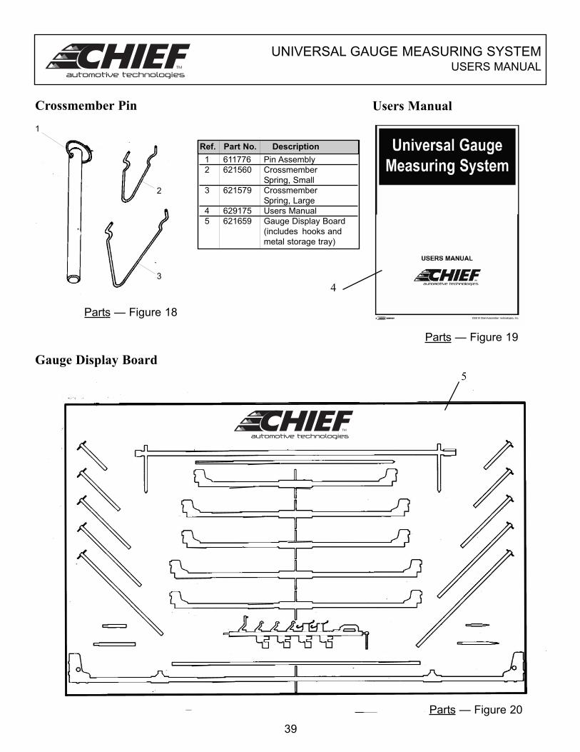
Crossmember Pin Users Manual
Gauge Display Board
1 611776 Pin Assembly
2 621560 Crossmember
Spring, Small
3 621579 Crossmember
Spring, Large
4 629175 Users Manual
5 621659 Gauge Display Board
(includes hooks and
metal storage tray)
Ref. Part No. Description
39
1
2
3
5
4
Parts — Figure 18
Parts — Figure 19
Parts — Figure 20


P.O. Box 1368
Grand Island, Nebraska 68802-1368
Phone: 308-384-9747
Fax: 308-384-8966
www.chiefautomotive.com
Form UGMS (Rev. 2/07)
Part No. 629175
Chief reserves the right to alter product specifications
and/or package components without notice.