Embed Size (px)
Citation preview

KELE • www.kele.com • FAX 901-372-2531 USA 901-937-4900 • International 001-901-382-6084
UNIVERSAL CALIBRATION KIT INSTRUCTION MANUAL
UCK SERIES
revised August 2016
Congratulations! You are the proud owner of a Kele Model UCK calibration kit! This collection of hard-to-find fittings, adapters, and tubing enables connection to a wide variety of gas sensors that Kele sells. In addition, the use of simple inline restrictors and a reliable PG-05 pressure gauge allows the accurate establishment of any desired flow rate from 50 ml/min to 1.0 lpm.
The Model UCK-1 contains a 51-226AB6610 regulator for non-corrosive gases (N2, CO2, CH4, H2, O2, CO, refrigerants). The Model UCK-2 contains a UCKR58 regulator for corrosive gases (NO2, H2S, SO2, NH3). The Model UCK-3 contains both regulators. Gases (ordered separately) are shipped in 17-liter steel cylinders for non-corrosives and 58-liter aluminum cylinders for corrosives.
PART NUMBERUCKBOX51-226AB6610 (in UCK-1 or UCK-3)UCKR58 (In UCK-2 or UCK-3)UCKT2UCKT3UCKT4UCKT5X-B-261X-B-373UCKCAPUCKGMTPG-05R-3710-2005R-3710-2007UCKMANUALX-M-102X-B-130X-28-4-4CMD-Calhose Kit
DESCRIPTIONHigh-impact poly toolboxRegulator for 17L gas cylinders (non-corrosives)Regulator for 58L gas cylinders (corrosive gases)30'' x 3/32'' x ID x 5/32'' OD tubing, green transparent30'' x 1/8'' ID x 1/4'' OD tubing, red transparent30'' x 5/32'' ID 9/32'' OD tubing, yellow transparent30'' x 3/16'' ID 5/16'' OD tubing, blue transparent5/32'' x 1/4'' barbed coupling1/4'' x 1/4'' x 1/8'' FNPT gauge tee1/4'' barbed adapter on 1'' PVC cap for Figaro© type sensorsGMT calibration plug adapter30 psig gauge 1/8'' MNPT0.005'' inline restrictor, 1/4'' x 1/4'' barbed0.007'' inline restrictor, 1/4'' x 1/4'' barbedInstruction manual/flow table1/4" MPT pipe plug3/16" x 1/8" MPT adapter1/4'' barbed x 1/4'' MPTGas adapter
PARTS INCLUDED (Use part numbers listed to order replacements)
1
The tubing and fittings included in the Model UCK were selected to allow easy assembly of an airtight path for calibration gas to flow across the sensing element (or through the sensing chamber) of the full spectrum of gas sensors offered by Kele. Instructions for piping to each of these are included below. In addition, most competitive gas sensors can be rigged for calibration with the Model UCK’s five sizes of tubing and assortment of both barbed and special fittings.
NOTE: This manual is a guide to connecting the included components to various gas sensors, and establishing the sensor manufacturer’s recommended gas flow rate. It is not a substitute for the sensor manufacturer’s instructions for checking and adjusting calibration in the field. Refer to manufacturer’s literature for recommended flow rates, flow durations, and adjustments.
KELE • www.kele.com • FAX 901-372-2531 USA 901-937-4900 • International 001-901-382-6084
UPSTREAMPRESSURE
(psig)
123456789101112131415
0.005"RESTRICTOR
FLOW(ml/min)
507895
110123135146156165174182191198206213
0.007" FRESTRICTOR
FLOW(ml/min)
160221271313350383414443470495519542564586606
UPSTREAMPRESSURE
(psig)
161718192021222324252627282930
0.005"RESTRICTOR
FLOW(ml/min)
220227233240246252258264269275280286291296300
0.007" FRESTRICTOR
FLOW(ml/min)
626645664682700717734751767783798813828843857
TABLE 2 FLOW TABLE
2
GENERAL OPERATION
The UCK has gained wide acceptance in the gas sensing market due to its unique method of establishing accurate flow rates of compressed gases at a very low cost. Gas flow rates from 50 milliliters per minute (ml/min or cc/min) to 1 liter per minute (lpm) are specified by the various sensor manufacturers. To cover this range, other calibration methods either rely on the use of a very expensive flow meter for varying rates, or the purchase of multiple fixed-rate orifice style regulators. The UCK calibration kit accomplishes the same thing with a standard 1.0 lpm regulator, a PG-05 pressure gauge, and two conventional inline restrictors in the following fashion:
The regulator supplied with the kit contains an orifice that supplies a fixed flow of 1.0 lpm, provided that there are no significant downstream restrictions that would cause a large (>1 psig) pressure drop at that flow rate. For sensors requiring 1.0 lpm flow, simply connect the blue (3/16" ID) tubing directly to the regulator; then, use appropriate reducers, tubing, and adapters to direct the gas to the sensor in ques-tion. Open the regulator valve fully to produce 1.0 lpm flow. Refer to the following section for suggested methods for a number of sensors.
To establish flow rates below 1.0 lpm, connect the PG-05 pressure gauge and X-B-373 tee to the regu-lator with a short (2-3") length of blue (3/16" ID) tubing. Connect one of the inline restrictors (0.005" or 0.007") to the downstream side of the gauge tee with a short (2-3") length of yellow (5/32" ID) tubing. Choose the restrictor based on the table below. Connect to the downstream side of the restrictor with another length of yellow (5/32" ID) tubing; then, use appropriate reducers, tubing, and adapters to direct the gas to the sensor in question (see Diagrams 1 & 2 on pages 3-8). Adjust the regulator valve to sup-ply the desired upstream pressure to the restrictor, and the flow rate in the table below will be produced, again providing that no significant downstream restrictions are present that would cause a large (>1 psig) pressure drop at that flow rate. Refer to the following section for suggested methods for a number of sen-sors.

CONNECTING TO SENSORS
KELE • www.kele.com • FAX 901-372-2531 USA 901-937-4900 • International 001-901-382-60843
2-3" Blue Tubing
Regulator
PG-05Gauge
2-3" Yellow Tubing
0.005"Restrictor
X-B-261 Reducer
Green Tubingto Device
X-B-373X-B-130
ENGELHARD 7001 AND 8002 SERIES CO2 SENSORS
2-3" Blue Tubing
Regulator
PG-05Gauge
2-3" Yellow Tubing
Masking Tape
0.005''Restrictor
Remainder ofYellow Tubing
X-B-130X-B-373
TELAIRE 2001 AND 1502 SERIES CO2 SENSORS
The key to performing an accurate calibration (or check) of a gas sensor is to introduce the calibration gas to the sensing element in a way that prevents mixing with the ambient air and to match the manufac-turer’s recommended flow rate as closely as possible. This is done by maintaining a calibration gas pres-sure at the sensor that is very slightly positive with respect to the ambient air. Too much pressure can cause errors since it would tend to increase the number of gas molecules at the sensor. Typically, the manufacturer’s recommended flow rates and the connecting fittings are chosen to accomplish this goal. The following connections are specifically related to the types of sensors available from Kele. With a little creativity, UCK components can also be arranged to connect with many other types of sensors.
Use the GAS-CO2-2000 along with 17l regulator (51-226AB6610) and X-B-130 along with UCKT4 & 5 tubing, R-3710-2005 resistor, X-B-373 fitting and PG-05 gauge. The 2001V-3 has an optical bench assembly consisting of 9 sensing ports (5 on either side and 4 on the front). It is necessary to mask off all but 2 of the ports on the optical bench assembly with masking tape. Mask off the ports on both sides and mask off the two middle ports on the front of the sensing block, leaving the top and bottom ports on the front open. To connect to the 2001V-3 it is necessary to push the open end of the yellow tubing into one of the two ports that have been covered by the masking tape. This will allow gas flow throughout the optical bench assembly. The fit will be tight, as it needs to be. Do not use any type of lubricant to assist in the working the yellow tubing into the port on the optical bench assembly. The gas flow should be about 200 ml/min or 14 psi on the gauge. Then follow the manufacturer’s installation instructions to complete calibration.
Cut squarely the end of the green (3/32" ID) UCKT2 tubing and insert firmly into the calibration port on the bottom (8002) or back (7001) of the enclosure, until it stays by itself. Use a X-B-261 reducing fitting to connect the other end of the green tubing to a short (2-3") length of yellow (5/32" ID) UCKT4 tubing, which goes to the 0.005" R-3710-2005 restrictor. From the restrictor, connect with a second short (2-3") length of yellow (5/32" ID) tubing to the X-B-373 fitting and attach the PG-05 gauge. From the gauge to the 51-226AB6610 regulator and X-B-130, use a short (2-3") length of blue (3/16" ID) UCKT5 tubing. Adjust flow rates for these products to approximately 80 ml/min (about 2 psig on the PG-05 gauge). Then follow the manufacturer’s installation instructions to complete calibration.
KELE • www.kele.com • FAX 901-372-2531 USA 901-937-4900 • International 001-901-382-60844
2-3" Blue Tubing
Regulator
PG-05Gauge
2-3" Yellow Tubing
0.007''Restrictor
X-B-261 Reducer
Red Tubingto Device
X-B-373X-B-130
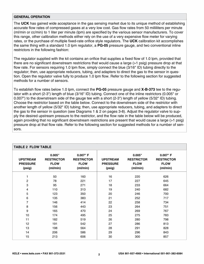
TEXAS INSTRUMENTS 4GS SERIES CO2 SENSORS
2-3" Blue Tubing
Regulator
PG-05Gauge
�-3� � e��� � � u���g
0�00����e��� �����
�e�a���e����� � e��� � � u���g���e���e���u��� �� �������e ���e
X-B-373
X-B-130
KELE CD-1D/CD-AD CO2 SENSORS
2-3" Blue Tubing
Regulator
PG-05Gauge
2-3" Yellow Tubing
0.005''Restrictor
Red Tubingto Device
X-B-261 Reducer
X-B-373
X-B-130
KELE CD-1W/CD-AW CO2 SENSORS
Remove the cap from the calibration gas connection at the bottom of the enclosure. Connect to the sen-sor with the red (1/8" ID) UCKT3 tubing. Use a X-B-261 reducing fitting to connect the red tubing to a short (2-3") length of yellow (5/32" ID) UCKT4 tubing, then to the 0.007" R-3710-2007 restrictor. Use a second short (2-3") length of yellow (5/32" ID) tubing from the restrictor to the X-B-373 and attach the PG-05 gauge. From the gauge to the 51-226AB6610 regulator and X-B-130, use a short (2-3") length of blue (3/16" ID) UCKT5 tubing. Adjust flow rates for these products to approximately 500 ml/min (about 10 psig on the PG-05 gauge). Then follow the manufacturer’s installation instructions to complete calibration.
With the sensor open, remove the cap from the calibration gas connection on the side of the optical chamber. Connect to the sensor with the red (1/8" ID) UCKT3 tubing. Use a X-B-261 reducing fitting to connect to a short (2-3") length of yellow (5/32" ID) UCKT4 tubing, then to the 0.005" R-3710-2005 restrictor. Use another short (2-3") length of yellow (5/32" ID) tubing from the restrictor to the X-B-373 fitting and attach the PG-05 gauge. From the gauge to the 51-226AB6610 regulator and X-B-130 use a short (2-3") length of blue (3/16" ID) UCKT5 tubing. Adjust flow rates for these products to approximately 100 ml/min (about 4 psig on the PG-05 gauge). Then follow the manufacturer’s installation instructions to complete calibration.
Use a short (2-3") length of blue (3/16" ID) UCKT5 tubing from the 51-226AB6610 regulator and X-B-130 to the X-B-373 fitting and attach the PG-05 gauge, then a short (2-3") length of yellow (5/32" ID) UCKT4 tubing to the 0.005" R-3710-2005 restrictor. Connect from the restrictor to either of the duct ports on the base of the CD-1D with the remainder of the yellow (5/32" ID) tubing. Adjust flow rates for these products to approximately 100 ml/min (about 4 psig on the PG-05 gauge). Then follow the manufacturer’s installation instructions to complete calibration.

KELE • www.kele.com • FAX 901-372-2531 USA 901-937-4900 • International 001-901-382-60845
2-3" Blue Tubing
Regulator
PG-05Gauge
2-3" Yellow Tubing
0.005'' or 0.007''Restrictor
Remainder of Yellow Tubing
Use Either Port(other one is vent)
GMT Adapterwith O-Ring
X-B-373
X-B-130
KELE GMT SERIES TOXIC / COMBUSTIBLE GAS SENSORS
GAS
Carbon monoxide (CO) - S1Carbon monoxide (CO) - S2Nitrogen dioxide (NO2) - S1Hydrogen (H2) - S1Hydrogen (H2) - S2Chlorine (Cl2) - S1Combustibles - S2Ammonia (NH3) - S1Ammonia (NH3) - S2Hydrogen sulfide (H2S) - S1Hydrogen sulfide (H2S) - S2Oxygen (O2) - S1Sulfur dioxide (SO2) - S1
FLOW RATE (ml/min)
50080
50050080
100050080
100080
100080
500
RESTRICTOR/UPSTREAMPRESSURE
0.007" - 10 psig0.005" - 2 psig0.007" - 10 psig0.007" - 10 psig0.005" - 2 psig(no restrictor)0.007" - 10 psig0.005" - 2 psig(no restrictor)0.005" - 2 psig(no restrictor)0.005" - 2 psig0.007" - 10 psig
FLOW TABLE
2-3" Blue Tubing
Regulator
PG-05Gauge
2-3" Yellow Tubing
0.005"Restrictor
Red Tubingto Device
X-B-261 Reducer
X-B-373X-B-130
KELE RLD-IR SERIES INFRARED REFRIGERANT LEAK DETECTORS
Use a short (2-3") length of blue (3/16" ID) UCKT5 tubing from the regulator (Either 51-226AB6610 and X-B-130 or UCKR58) to the X-B-373 fitting and attach the PG-05 gauge, then a short (2-3") length of yellow (5/32" ID) UCKT4 tubing to either the 0.005/7" R-3710-2005/7 restrictor depending on the flow rate required (see Table 3 below). Con-nect the remainder of the yellow (5/32" ID) tubing from the restrictor to either of the ports on the GMT adapter (gray disk with two ports and an O-ring). Plug the adapter into the mating recess on the front cover of the GMT, or at the sensor end in an explosion proof GMT. Adjust flow rates for these products to the recommended values for the gas in question, as shown below. For gases not shown, contact a Kele Technical Sales Representative for additional information. Then follow the manufacturer’s installation instructions to complete calibration.
Open the front door of the RLD-IR and connect the red (1/8" ID) UCKT3 tubing to the barbed connector in the bot-tom of the housing (on the end of the tube coming from the optical chamber). Use the X-B-261 reducing coupling to connect with short (2-3") length of yellow (5/32" ID) UCKT4 tubing to the 0.005" R-3710-2005 restrictor. Connect the restrictor to the X-B-373 fitting and attach the PG-05 gauge with a second short (2-3") length of yellow (5/32" ID) tubing. From the gauge to the 51-226AB6610 regulator and X-B-130, use a short (2-3") length of blue (3/16" ID) UCKT5 tubing. Adjust flow rates for these products to approximately 300 ml/min (30 psig on the PG-05 gauge). Then follow the manufacturer’s installation instructions to complete calibration.

KELE • www.kele.com • FAX 901-372-2531 USA 901-937-4900 • International 001-901-382-60846
2-3" Blue Tubing
Regulator
PG-05Gauge
2-3" Yellow Tubing
0.007"Restrictor
Remainder of Yellow Tubing
UCKCAPAdapter
�-B-373�-B-�30
KELE OS-1 OXYGEN SENSOR
2-3" Blue Tubing
Regulator
PG-05Gauge
2-3" Yellow Tubing
0.005" or 0.007"Restrictor
Remainder of Yellow Tubing
UCKCAPAdapter
X-B-373
X-B-130
KELE RLD-5 AND RLD-134a REFRIGERANT LEAK DETECTORS
The OS-1 oxygen sensor is designed to be calibrated in ambient air (20.95% Oxygen), and thus no calibration gas is generally needed; however, to check calibration or prove operation, the UCK may be connected. Use a short (2-3") length of blue (3/16" ID) UCKT5 tubing from the 51-226AB6610 regulator and X-B-130 to the X-B-373 fitting and attach the PG-05 gauge, then a short (2-3") length of yellow (5/32" ID) UCKT4 tubing to the 0.007" R-3710-2007 restrictor. Connect the remainder of the yellow (5/32" ID) tubing from the restrictor to X-B-130 fitting, and then one can drill a hole in the all-purpose cap adapter (UCKCAP) and attach the fitting. The OS-1 sensing element is located in the 1" fitting that protrudes from the bottom of the unit. Mate the UCKCAP to the OS-1 fitting and hold or secure with tape on two sides only. Do not completely seal the gap between the fittings since it is needed to vent the spent gas. Adjust flow rates for these products to approximately 500 ml/min (10 psig on the PG-05 gauge). Then follow the manufacturer’s installation instructions to complete calibration.
Calibration of these sensors does not require the use of calibration gas; however, to check calibration or prove operation, the UCK may be connected. Use a short (2-3") length of blue (3/16" ID) UCKT5 tubing from the 51-226AB6610 regulator and X-B-130 to the X-B-373 fitting and attach the PG-05 gauge, then a short (2-3") length of yellow (5/32" ID) UCKT4 tubing to the 0.005/7" R-3710-2005/7 restrictor. Connect the remainder of the yellow (5/32" ID) tubing from the restrictor to X-B-130 fitting, and then one can drill a hole in the all-purpose cap adapter (UCKCAP) and attach the fitting. The RLD-5 and RLD-134a sens-ing element is located on the front of the unit. Simply cover the sensor with the UCKCAP all-purpose adapter and hold it flush with the cover, or secure it with tape on two sides only. Do not completely seal the gap between the UCKCAP and the cover since it is needed to vent the spent gas. Adjust flow rates for these products to approximately 200 ml/min (14 psig on the PG-05 gauge). Then follow the manufac-turer’s installation instructions to complete calibration.

KELE • www.kele.com • FAX 901-372-2531 USA 901-937-4900 • International 001-901-382-60847
2-3" Blue Tubing
Regulator
PG-05Gauge
2-3" Yellow Tubing
0.005" or 0.007"Restrictor
Remainder of Yellow Tubing
UCKCAPAdapter
X-B-373X-B-130
KELE WCO-1B AND WCO-1D CARBON MONOXIDE SENSORS
2-3" Blue Tubing
Regulator
PG-05Gauge
�-3� � e��� � � u���g
0�007��e��� �����
�e�a���e������ e��� � � u���g
UCKCAP��a��e�
X-B-373X-B-130
SPC3-1000/3000 SERIES TOXIC / COMBUSTIBLE GAS SENSORS
Use a short (2-3") length of blue (3/16" ID) UCKT5 tubing from the 51-226AB6610 regulator and X-B-130 to the X-B-373 fitting and attach the PG-05 gauge, then a short (2-3") length of yellow (5/32" ID) UCKT4 tubing to the 0.005/7" R-3710-2005/7 restrictor. Connect the remainder of the yellow (5/32" ID) tubing from the restrictor to X-B-130 fitting, and then one can drill a hole in the all-purpose cap adapter (UCK-CAP) and attach the fitting. Open the WCO product to expose the sensing element (a cylindrical device labeled “Figaro TGS” on top). Simply place the UCKCAP over the sensor loosely and adjust the flow rate to approximately 80 ml/min for these products (2 psig on the PG-05 gauge). Then follow the manufac-turer’s installation instructions to complete calibration.
Use a short (2-3") length of blue (3/16" ID) UCKT5 tubing from the regulator (Either 51-226AB6610 and X-B-130 or UCKR58) to the X-B-373 fitting and attach the PG-05 gauge, then a short (2-3") length of yellow (5/32" ID) UCKT4 tubing to the 0.007" R-3710-2007 restrictor. Connect the remainder of the yel-low (5/32" ID) tubing from the restrictor to X-B-130 fitting, and then one can drill a hole in the all-purpose cap adapter (UCKCAP) and attach the fitting. If the sensor is in very tight quarters or the area is breezy, a length of duct tape may be formed into a skirt around the UCKCAP to concentrate the gas flow around the sensor. Do not completely seal the UCKCAP to the sensor since a gap is needed to vent the spent gas. Adjust flow rates for these products to the recommended values for the gas in question, as shown below. For gases not shown, contact a Kele Technical Sales Representative for additional information. Then follow the manufacturer’s installation instructions to complete calibration.
KELE • www.kele.com • FAX 901-372-2531 USA 901-937-4900 • International 001-901-382-60848
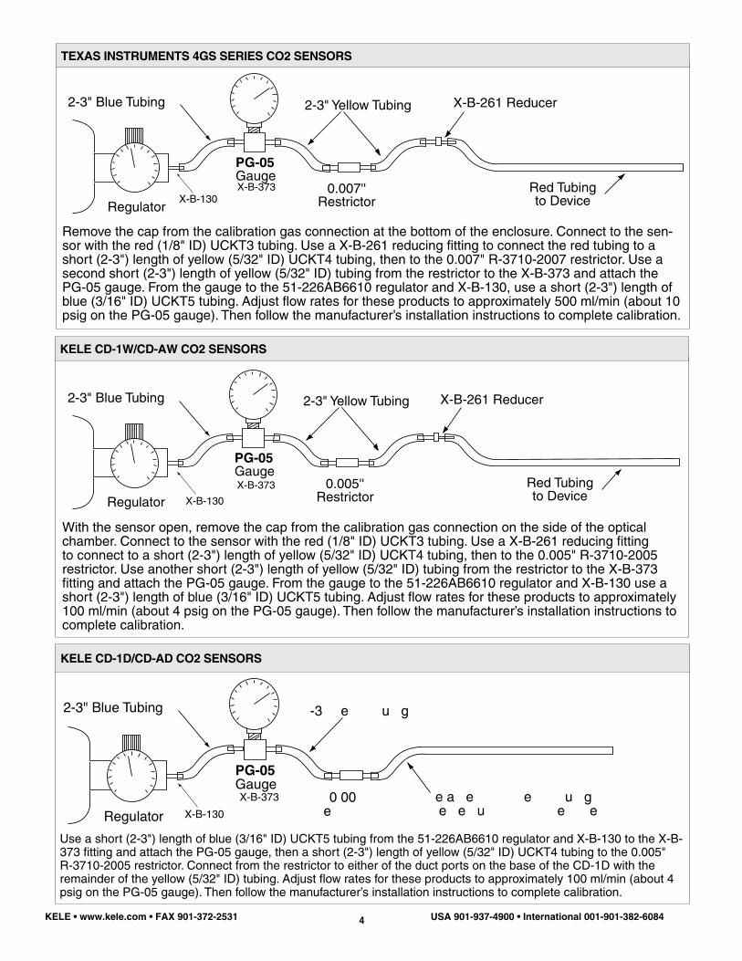
GAS
Carbon monoxide (CO) Nitrogen dioxide (NO2)Hydrogen (H2)CombustiblesOxygen (O2)Ammonia (NH3)
FLOW RATE (ml/min)
150150300300150150
RESTRICTOR/UPSTREAMPRESSURE
0.007" - 1 psig0.007" - 1 psig0.007" - 4 psig0.007" - 4 psig0.007" - 1 psig0.007" - 1 psig
FLOW RATE TABLE 4
2-3" Blue Tubing
Regulator
PG-05Gauge
2-3" Yellow Tubing
0.005''Restrictor
Red Tubingto Device
X-B-261 Reducer
X-B-373X-B-130
KELE KCD/W, KCO2, KCOC, KCOP AND KTS SERIES
2-3" Blue Tubing
Regulator
PG-05Gauge
�-3� � e��� � � u���g
0�00����e��� �����
�e�a���e����� � e��� � � u���g���e���e���u��� �� �������e ���e
X-B-373X-B-130
DWYER CDT SERIES CO2 SENSORS
The Dwyer CDT series Connect to the sensor with the red (1/8" ID) UCKT3 tubing. Use a X-B-261 reducing fitting to connect the red tubing to a short (2-3") length of yellow (5/32" ID) UCKT4 tubing, then to the 0.005" R-3710-2005 restrictor. Use a second short (2-3") length of yellow (5/32" ID) tubing from the restrictor to the X-B-373 fitting and attach the PG-05 gauge. From the gauge to the 51-226AB6610 regulator and X-B-130 use a short (2-3") length of blue (3/16" ID) UCKT5 tubing. Adjust flow rates for these products to approximately 300 ml/min (about 4 psig on the PG-05 gauge). Then follow the manu-facturer’s installation instructions to complete calibration.
Connect to the sensor with the red (1/8" ID) UCKT3 tubing. Use a X-B-261 reducing fitting to connect the red tubing to a short (2-3") length of yellow (5/32" ID) UCKT4 tubing, then to the 0.005" R-3710-2005 restrictor. Use a second short (2-3") length of yellow (5/32" ID) tubing from the restrictor to the X-B-373 fitting and attach the PG-05 gauge. From the gauge to the 51-226AB6610 regulator and X-B-130 use a short (2-3") length of blue (3/16" ID) UCKT5 tubing. Adjust flow rates for these products to approximately 50 ml/min (about 1 psig on the PG-05 gauge). Then follow the manufacturer’s installation instructions to complete calibration.

KELE • www.kele.com • FAX 901-372-2531 USA 901-937-4900 • International 001-901-382-60849
2-3" Blue Tubing
Regulator
PG-05Gauge
2-3" Yellow Tubing
0.007''Restrictor
Red Tubingto Device
X-B-261 Reducer
X-B-373X-B-130
GMD/W SENSOR
2-3" Blue Tubing
Regulator
PG-05Gauge
�-3� � e��� � � u���g
0�007��e��� �����
�e�a���e������ e��� � � u���g
UCKCAP��a��e�
X-B-373
X-B-130
KELE GDS/GDD/GDN SERIES TOXIC / COMBUSTIBLE GAS SENSORS
With the sensor open, remove the cap from the calibration gas connection on the side of the optical chamber. Connect to the sensor with the red (1/8" ID) UCKT3 tubing. Use a X-B-261 reducing fitting to connect to a short (2-3") length of yellow (5/32" ID) UCKT4 tubing, then to the 0.007" R-3710-2007 restrictor. Use another short (2-3") length of yellow (5/32" ID) tubing from the restrictor to the X-B-373 fitting and attach the PG-05 gauge. From the gauge to the 51-226AB6610 regulator and X-B-130 use a short (2-3") length of blue (3/16" ID) UCKT5 tubing. Ad-just flow rates for these products to approximately 600 ml/min (about 15 psig on the PG-05 gauge). Then follow the manufacturer’s installation instructions to complete calibration.
2-3" Blue Tubing
Regulator
PG-05Gauge
2-3" Yellow Tubing
0.005''Restrictor
Red Tubingto Device
X-B-261 Reducer
X-B-373
X-B-130
IR-F9 SENSORS
The device has a draw chamber with a barbed connector which is the red (1/8" ID) UCKT3 tubing. Use the X-B-261 reducing coupling to connect with short (2-3") length of yellow (5/32" ID) UCKT4 tubing to the 0.005" R-3710-2005 restrictor. Connect the restrictor to the X-B-373 fitting and attach the PG-05 gauge with a second short (2-3") length of yellow (5/32" ID) tubing. From the gauge to the 51-226AB6610 regulator and X-B-130 use a short (2-3") length of blue (3/16" ID) UCKT5 tubing. Adjust flow rates for these products to approximately 100 ml/min (4 psig on the PG-05 gauge). Then follow the manufacturer’s installation instructions to complete calibration.
Use a short (2-3") length of blue (3/16" ID) UCKT5 tubing from the regulator (Either 51-226AB6610 or UCKR58) to the X-B-373 fitting and attach the PG-05 gauge, then a short (2-3") length of yellow (5/32" ID) UCKT4 tubing to the 0.007" R-3710-2007 restrictor. Connect the remainder of the yellow (5/32" ID) tubing from the restrictor to X-B-130 fitting, and then one can drill a hole in the all-purpose cap adapter (UCKCAP) and attach the fitting. Plug the adapter into the mating recess on the front cover of the GDS/GDD/GDN, or at the sensor end in an explosion proof SPX. Adjust flow rates for these products to the recommended values for the gas in question, as shown below. For gases not shown, contact a Kele Technical Sales Representative for additional information. Then follow the manu-facturer’s installation instructions to complete calibration.
KELE • www.kele.com • FAX 901-372-2531 USA 901-937-4900 • International 001-901-382-608410
GAS
Carbon monoxide (CO) Nitrogen dioxide (NO2)Hydrogen (H2)CombustiblesHydrogen sulfide (H2S)Oxygen (O2) - S1
FLOW RATE (ml/min)
500500500500
100080
RESTRICTOR/UPSTREAMPRESSURE
0.007" - 10 psig0.007" - 10 psig0.007" - 10 psig0.007" - 10 psig(no restictor)0.005" - 2 psig
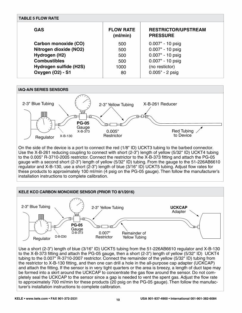
TABLE 5 FLOW RATE
2-3" Blue Tubing
Regulator
PG-05Gauge
2-3" Yellow Tubing
0.007"Restrictor
Remainder of Yellow Tubing
UCKCAPAdapter
�-B-373�-B-�30
KELE KCO CARBON MONOXIDE SENSOR (PRIOR TO 8/1/2016)
2-3" Blue Tubing
Regulator
PG-05Gauge
2-3" Yellow Tubing
0.005''Restrictor
Red Tubingto Device
X-B-261 Reducer
X-B-373X-B-130
IAQ-A/N SERIES SENSORS
On the side of the device is a port to connect the red (1/8" ID) UCKT3 tubing to the barbed connector. Use the X-B-261 reducing coupling to connect with short (2-3") length of yellow (5/32" ID) UCKT4 tubing to the 0.005" R-3710-2005 restrictor. Connect the restrictor to the X-B-373 fitting and attach the PG-05 gauge with a second short (2-3") length of yellow (5/32" ID) tubing. From the gauge to the 51-226AB6610 regulator and X-B-130, use a short (2-3") length of blue (3/16" ID) UCKT5 tubing. Adjust flow rates for these products to approximately 100 ml/min (4 psig on the PG-05 gauge). Then follow the manufacturer’s installation instructions to complete calibration.
Use a short (2-3") length of blue (3/16" ID) UCKT5 tubing from the 51-226AB6610 regulator and X-B-130 to the X-B-373 fitting and attach the PG-05 gauge, then a short (2-3") length of yellow (5/32" ID) UCKT4 tubing to the 0.007" R-3710-2007 restrictor. Connect the remainder of the yellow (5/32" ID) tubing from the restrictor to X-B-130 fitting, and then one can drill a hole in the all-purpose cap adapter (UCKCAP) and attach the fitting. If the sensor is in very tight quarters or the area is breezy, a length of duct tape may be formed into a skirt around the UCKCAP to concentrate the gas flow around the sensor. Do not com-pletely seal the UCKCAP to the sensor since a gap is needed to vent the spent gas. Adjust the flow rate to approximately 700 ml/min for these products (20 psig on the PG-05 gauge). Then follow the manufac-turer’s installation instructions to complete calibration.

KELE • www.kele.com • FAX 901-372-2531 USA 901-937-4900 • International 001-901-382-608411
2-3" Blue Tubing
Regulator
PG-05Gauge
2-3" Yellow Tubing
0.007''Restrictor
Red Tubingto Device
X-B-261 Reducer
X-B-373X-B-130
VA301RFS SERIES SENSORS
On the side of the device is a port to connect the red (1/8" ID) UCKT3 tubing to the barbed connec-tor. Use the X-B-261 reducing coupling to connect with short (2-3") length of yellow (5/32" ID) UCKT4 tubing to the 0.007" R-3710-2007 restrictor. Connect the restrictor to the X-B-373 fitting and attach the PG-05 gauge with a second short (2-3") length of yellow (5/32" ID) tubing. From the gauge to the 51-226AB6610 regulator and X-B-130 use a short (2-3") length of blue (3/16" ID) UCKT5 tubing. Adjust flow rates for these products to approximately 500 ml/min (10 psig on the PG-05 gauge). Then follow the manufacturer’s installation instructions to complete calibration.
2-3" Blue Tubing
Regulator
PG-05Gauge
2-3" Yellow Tubing
0.007"Restrictor
Remainder of Yellow Tubing
���-�����������
�-B-373�-B-�30
KELE KCO CARBON MONOXIDE SENSOR (AFTER TO 8/1/2016)
Use a short (2-3") length of blue (3/16" ID) UCKT5 tubing from the 51-226AB6610 regulator and X-B-130 to the X-B-373 fitting and attach the PG-05 gauge, then a short (2-3") length of yellow (5/32" ID) UCKT4 tubing to the 0.007" R-3710-2007 restrictor. Connect the remainder of the yellow (5/32" ID) tubing from the restrictor to X-B-130 fitting, and attach CMD-Calhose Kit. Adjust the flow rate to approximately 700 ml/min for these products (20 psig on the PG-05 gauge). Then follow the manufacturer’s installation instruc-tions to complete calibration.

2-3" Blue Tubing
Regulator
PG-05Gauge
2-3" Yellow Tubing
0.005"Restrictor
Remainder of Yellow Tubing
UCKCAPAdapter
X-B-373X-B-130
GDC-150/350 SERIES TOXIC/COMBUSTIBLE GAS SENSORS
Use a short (2-3") length of blue (3/16" ID) UCKT5 tubing from the regulator (Either 51-226AB6610 and X-B-130 or UCKR58) to the X-B-373 fitting and attach the PG-05 gauge, then a short (2-3") length of yellow (5/32" ID) UCKT4 tubing to the 0.007" R-3710-2007 restrictor. Connect the remainder of the yellow (5/32" ID) tubing from the restrictor to X-B-130 fitting, and then one can drill a hole in the all-pur-pose cap adapter (UCKCAP) and attach the fitting. Cover on the front cover of the GDC-150/350. Adjust flow rates for these products to the recommended values for the gas in question, as shown below. For gases not shown, contact a Kele Technical Sales Representative for additional information. Then follow the manufacturer’s installation instructions to complete calibration.
TABLE 6 FLOW RATE
2-3" Blue Tubing
Regulator
PG-05Gauge
2-3" Yellow Tubing
0.007"Restrictor
Remainder of Yellow Tubing
UCKCAPAdapter
�-B-373�-B-�30
S301 SENSORS
Use a short (2-3") length of blue (3/16" ID) UCKT5 tubing from the regulator (Either 51-226AB6610 and X-B-130 or UCKR58) to the X-B-373 fitting and attach the PG-05 gauge, then a short (2-3") length of yellow (5/32" ID) UCKT4 tubing to the 0.007" R-3710-2007 restrictor. Connect the remainder of the yellow (5/32" ID) tubing from the restrictor to X-B-130 fitting, and then one can drill a hole in the all-pur-pose cap adapter (UCKCAP) and attach the fitting. Simply place the UCKCAP over the sensor loosely and adjust the flow rate to the manufacturer’s recommended level (see below for restrictor and pressure choice). If the sensor is in very tight quarters or the area is breezy, a length of duct tape may be formed into a skirt around the UCKCAP to concentrate the gas flow around the sensor. Do not completely seal the UCKCAP to the sensor since a gap is needed to vent the spent gas. Then follow the manufacturer’s installation instructions to complete calibration.
GAS
Carbon monoxide (CO) Nitrogen dioxide (NO2)
FLOW RATE (ml/min)
500500
RESTRICTOR/UPSTREAMPRESSURE
0.007" - 10 psig0.007" - 10 psig

KELE • www.kele.com • FAX 901-372-2531 USA 901-937-4900 • International 001-901-382-608413
GAS
Carbon monoxide (CO) Nitrogen dioxide (NO2)Hydrogen (H2)CombustiblesRefridgerantsOxygen (O2) - S1Nitrogen oxide (NO)Sulfur dioxide (SO2)
FLOW RATE (ml/min)
500500500500500500500500
RESTRICTOR/UPSTREAMPRESSURE
0.007" - 10 psig0.007" - 10 psig0.007" - 10 psig0.007" - 10 psig0.007" - 10 psig0.007" - 10 psig0.007" - 10 psig0.007" - 10 psig
TABLE 7 FLOW RATE
GAS
Nitrogen dioxide (NO2) Sulfur dioxide (SO2)
FLOW RATE (ml/min)
500500
RESTRICTOR/UPSTREAMPRESSURE
0.007" - 10 psig0.007" - 10 psig
TABLE 8 FLOW RATE
2-3" Blue Tubing
Regulator
AGM-SZ SERIES SENSORS
Get plastic bag and put AGM-SZ sampling tube inside. Use GAS-NH3-1000 and UCKR58 regulator along with UCKT5 tubing. Then flow gas from regulator and tubing into plastic bag. The bag just needs to remain filled during calibration and because the AGM-SZ samples such a small volume; bag must be hand regulated. Then follow the manufacturer’s installation instructions to complete calibration.

KELE • www.kele.com • FAX 901-372-2531 USA 901-937-4900 • International 001-901-382-608414
2-3" Blue Tubing
Regulator
HGM-SZ/MZ SERIES SENSORS
2-3" Blue Tubing
Regulator
VASQN8 SERIES SENSORS
Get plastic bag and put HGM-SZ/MZ sampling tube inside. Use Refrigerant GAS-XX-XXX and 51-226AB6610 regulator along with UCKT5 tubing. Then flow gas from regulator and tubing into plastic bag. The bag just needs to remain filled during calibration and because the HGM-SZ/MZ samples such a small volume; bag must be hand regulated. Then follow the manufacturer’s installation instructions to complete calibration.
Use Refrigerant GAS-XX-XXX and 51-226AB6610 regulator along with UCKT3 7 5 tubing. Then flow gas from regulator and tubing into the VASQN8 sensor directly. Then follow the manufacturer’s installa-tion instructions to complete calibration.