Embed Size (px)
Citation preview

102
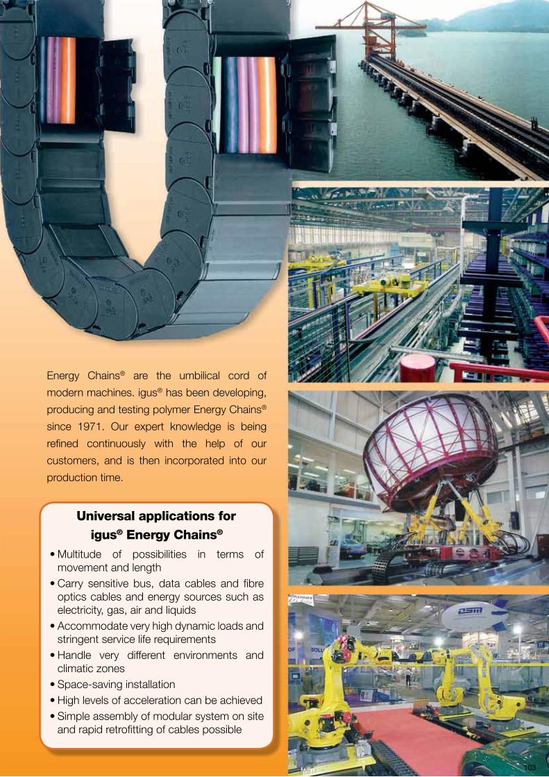
Energy Chains® are the umbilical cord of
modern machines. igus® has been developing,
producing and testing polymer Energy Chains®
since 1971. Our expert knowledge is being
refined continuously with the help of our
customers, and is then incorporated into our
production time.
Universal applications for igus® Energy Chains®
• Multitude of possibilities in terms of movement and length
• Carry sensitive bus, data cables and fibre optics cables and energy sources such as electricity, gas, air and liquids
• Accommodate very high dynamic loads and stringent service life requirements
• Handle very different environments and climatic zones
• Space-saving installation • High levels of acceleration can be achieved • Simple assembly of modular system on site
and rapid retrofitting of cables possible
103

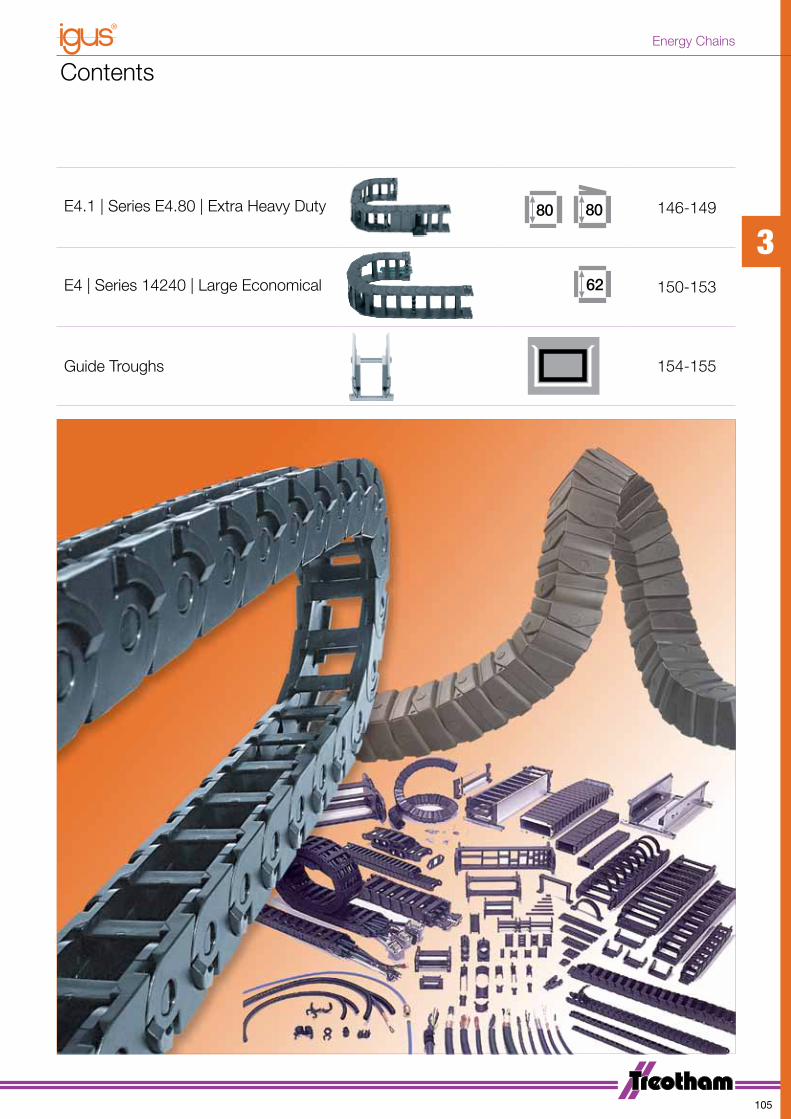
Contents
Design Information 106-109
Triflex-R | 3D E-Chain for Robotics
110-113
Easy Chain® | Series E08·Z08 14,714,6 114-115
Zipper | Series 15 1714,6 116-117
E2 E-Tubes | Series R48 25 118-119
E2 micro | Series 06 10,5 120-121
E2 mini | Series 10 18 122-123
E2/000 | Series 2400·2450·2480·2500 25 25 124-129
E2/000 | Series 2600·2650·2680·2700 130-135
E2/000 | Series 3400·3450·3480·3500 136-141
E4.1 | Series E4.56 | Extra Heavy Duty 142-145
3
104
Energy Chains
Contents
E4.1 | Series E4.80 | Extra Heavy Duty 146-149
E4 | Series 14240 | Large Economical 150-153
Guide Troughs 154-155
3
105
Energy Chains
Design Information
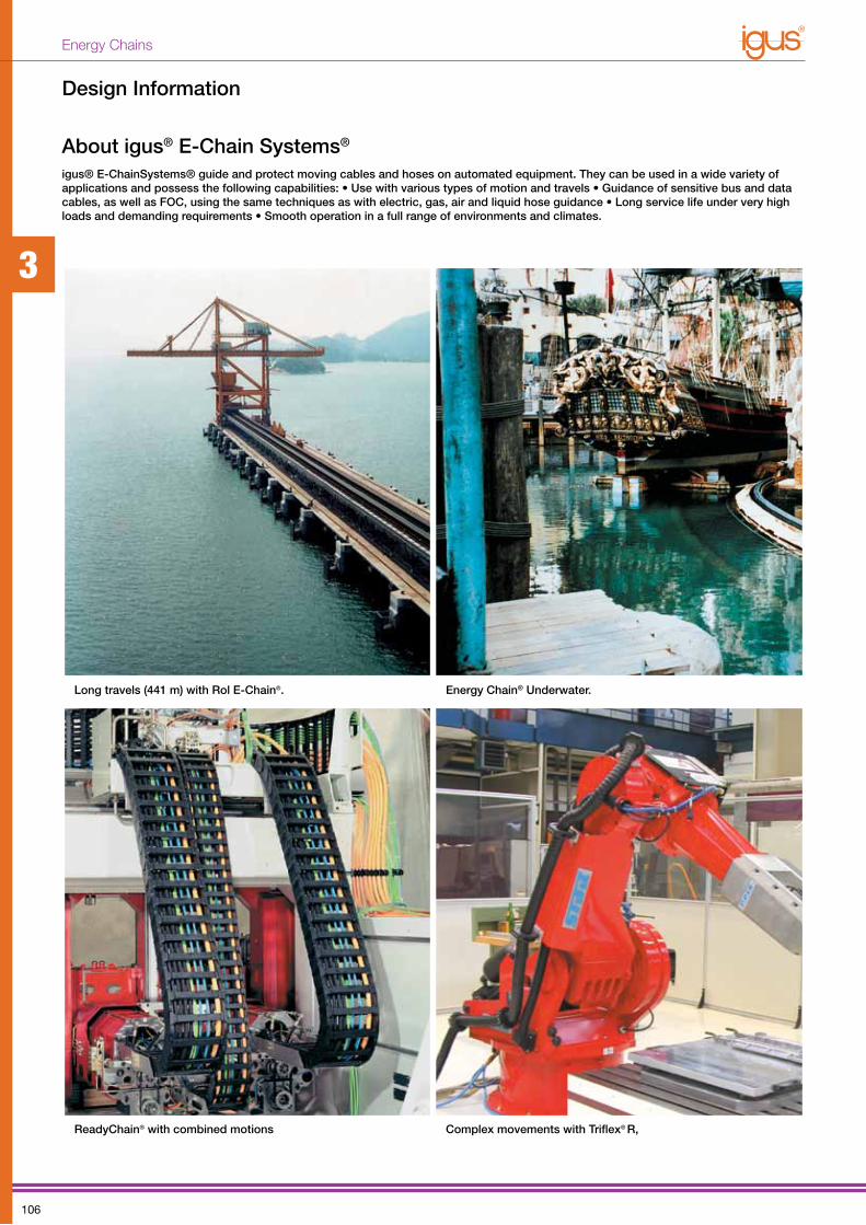
igus® E-ChainSystems® guide and protect moving cables and hoses on automated equipment. They can be used in a wide va rie ty of applications and possess the following capabilities: • Use with various types of motion and travels • Guidance of sensitive bus and data cables, as well as FOC, using the same techniques as with electric, gas, air and liquid hose guid ance • Long service life under very high loads and de manding re quirements • Smooth oper a tion in a full range of environ ments and climates.
About igus® E-Chain Systems®
Long travels (441 m) with Rol E-Chain®.
ReadyChain® with combined motions
Energy Chain® Underwater.
Complex movements with Triflex® R,
3
106
Energy Chains

Design Information
Calculation of chain length
This formula is generally valid for all types of applications if the fixed end is in the centre of the travel. Exceptions: rotary movements and most long travels.
Camber
LK = chain length
S = length of travel
K = Add-on length for bending radius (You can obtain the value “K” from the tables in the catalogue)
R = bending radius
Fixed end in the centre of the travel is the most favourable solution
H = nominal clearance height
HF = required clearance height
Principle of camber for igus® Energy Chains® HF = required installation height.
LK = S + K2
“Camber” is the curve of the upper run along its unsupported length. All igus® Energy Chains® are manufactured with camber. In the Instal-lation Dimensions section of each respective Energy Chain® description, you will find the measurement HF, which specifies the necessary clearance height, taking the camber into account. The camber allows for longer unsupported length and increases service life and operating safety. Upon request, we can deliver Energy Chains® without camber for restricted space applications; however, these “no-camber” chains do not have the same load-bearing capacity. Please consult Treotham.
If the fixed end of the Energy Chain® is located in the centre of the travel, the chain length “LK” is calculated by using half the length of travel and adding the value “K” for the curved length. (You can obtain the value “K” from the table in the catalogue.) Placing the fixed end in the centre of the travel is the most cost-effective solution because it requires the shortest Energy Chain®, cables and hoses.
HF
H
R
SS/2 S/2
3
107
Energy Chains

Filling | Cable and Hose Packages
Reasons for distribution rulesThe cables and hoses must be laid so that they
can move freely at all times and so that no tensile
force is exerted at the radius of the E-Chains®. For
high-speed applications and high cycles, cables
or hoses must not be laid on top of each other
without horizontal separa tion. The standard values
for this are: Travel speed over 0.5 m/s and cycles
over 10,000 p.a. igus® interior separation offers a
safe solution for this situation.
Further guidelines for dis tri bution The cable or hose weight should be symmetrically
distributed along the width of the E-Chain®. Cables
and hoses with different outer jacket materials must
not be allowed to “stick” together. If necessary, they
must be laid separately. All igus® Chainflex® cables
can be combined with each and other brands of
cable or hose. The cables and hoses should always
be fixed at the moving end. The fixed end should
always involve strain relief. Exceptions are made only
for certain hydraulic hoses with length com pensation
issues or other high pressure hoses (i.e. hydraulic
hoses).
10% min 2 mm
10%min 1 mm
10%min 1 mm
10% min 2 mm
10%min 1 mm
10%min 1 mm
D1
D2
d1 d2
D1 + D2 > 1,2 x hi
d1 + d2 ʺ 1,2 x hi
d1 + d2 ʺ 1,2 x hi
Clearance space “all around” for round electrical cables
Distribution rules:D1 + D2 > 1,2 x hi
Rule 1:
If D1 + D2 > 1.2 x E-Chain® inner
height, no separa tion be tween the two
cab les/ hoses is necessary. Two cables/ -
hoses should never be left unguided
on top of one an other or be allowed to
be come tangled.
d1 + d2 ≤ 1,2 x hi Rule 2:If d1 + d2 ≤ 1.2 x E-Chain® inner height,
a vertical se para tor or a horizontal shelf
must be used to reduce the inner height,
thereby preven ting the entanglement of
d1 and d2.
All-around clearance space in % for various cables/hoses
• Electrical round cables: 10%• Electrical flat cables: 10%• Pneumatics: 5-10%• Hydraulics: 20%• Media hoses: 15-20%
Various Applications
Side MountVertical Hanging Vertical Standing
Rotary MotionZig Zag Twister
3
108
Energy Chains
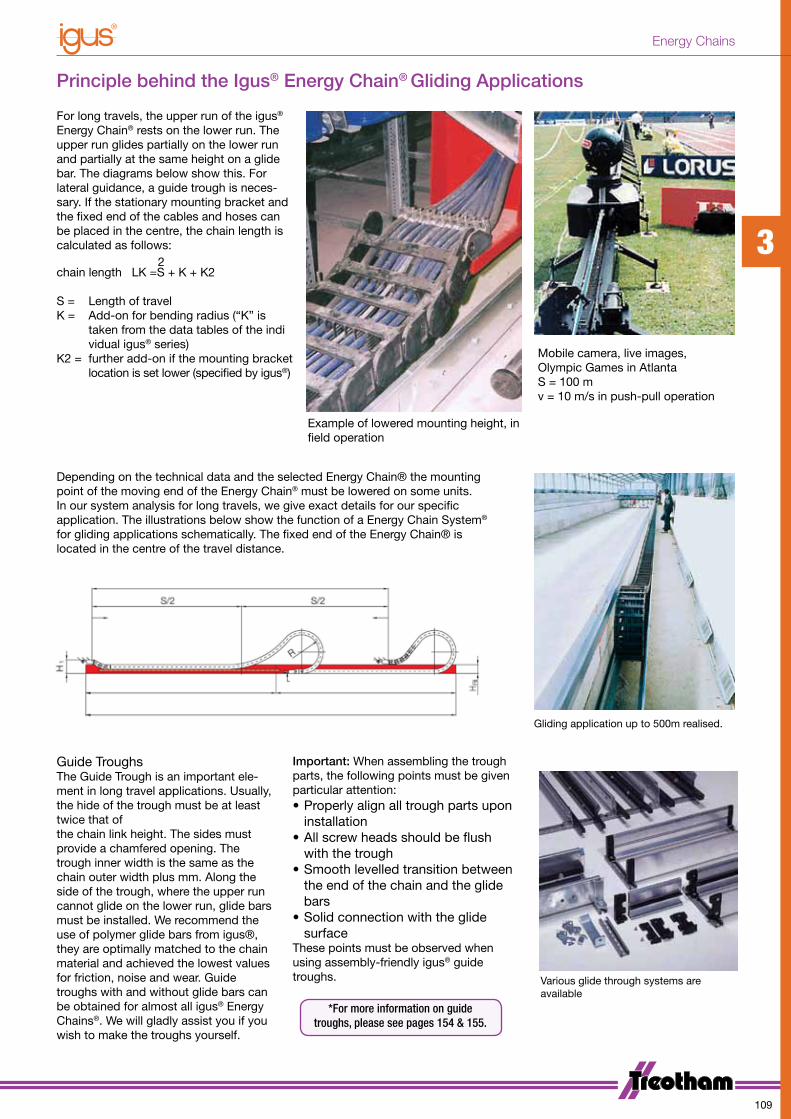
Principle behind the Igus® Energy Chain® Gliding Applications
Depending on the technical data and the selected Energy Chain® the mounting point of the moving end of the Energy Chain® must be lowered on some units. In our system analysis for long travels, we give exact details for our specific application. The illustrations below show the function of a Energy Chain System® for gliding applications schematically. The fixed end of the Energy Chain® is located in the centre of the travel distance.
Guide TroughsThe Guide Trough is an important ele-ment in long travel applications. Usually, the hide of the trough must be at least twice that ofthe chain link height. The sides must provide a chamfered opening. The trough inner width is the same as the chain outer width plus mm. Along the side of the trough, where the upper run cannot glide on the lower run, glide bars must be installed. We recommend the use of polymer glide bars from igus®, they are optimally matched to the chain material and achieved the lowest values for friction, noise and wear. Guide troughs with and without glide bars can be obtained for almost all igus® Energy Chains®. We will gladly assist you if you wish to make the troughs yourself.
Important: When assembling the trough parts, the following points must be given particular attention:• Properly align all trough parts upon
installation• All screw heads should be flush
with the trough• Smooth levelled transition between
the end of the chain and the glide bars
• Solid connection with the glide surface
These points must be observed when using assembly-friendly igus® guide troughs.
Mobile camera, live images,Olympic Games in AtlantaS = 100 mv = 10 m/s in push-pull operation
For long travels, the upper run of the igus® Energy Chain® rests on the lower run. The upper run glides partially on the lower run and partially at the same height on a glide bar. The diagrams below show this. For lateral guidance, a guide trough is neces-sary. If the stationary mounting bracket and the fixed end of the cables and hoses can be placed in the centre, the chain length is calculated as follows:
chain length LK =S + K + K2
S = Length of travelK = Add-on for bending radius (“K” is taken from the data tables of the indi vidual igus® series)K2 = further add-on if the mounting bracket location is set lower (specified by igus®)
2
Example of lowered mounting height, in field operation
Gliding application up to 500m realised.
Various glide through systems are available
*For more information on guide troughs, please see pages 154 & 155.
3
109
Energy Chains

Triflex-R | 3D-E-Chain® for robotics applications
TRC
Closed design, dirt-resistant
TRE “Easy” Design,simply press cables in
TRLThe light alternative with an “Easy” design
Series TRC - Dimensioning
Series TRE - Dimensioning
Series TRL - Dimensioning
3
110
Energy Chains

Triflex-R | TRC·TRE·TRL | Installation Dimensions
TRC TRE TRLPart No. Opening Inner
heightInner height
Outerwidth
Bending radii
max. ø cable
principle Bi 1 [mm] Bi 2 [mm] Ba [mm] R [mm] d1 [mm] d2 [mm]
TRE.30. 050.0 closed design 12 10 34,5 050 10 8
TRE.40. 058.0 closed design 15 13 43 058 13 11
TRE.60. 087.0 closed design 22,5 19,5 65 087 20,5 17,5
TRE.70. 110.0 closed design 28 24 81 110 26 22
TRE.85. 135.0 closed design 33 28 94,5 135 31 26
TRE.100.145.0 closed design 37,5 32,5 108 145 35,5 30,5
TRE.30. 050.0 simply press cables in 12 10 34,5 050 10 8
TRE.40. 058.0 simply press cables in 15 13 43 058 13 11
TRE.60. 087.0 simply press cables in 22,5 19,5 65 087 20,5 17,5
TRE.70. 110.0 simply press cables in 28 24 81 110 26 22
TRE.85. 135.0 simply press cables in 33 28 94,5 135 31 26
TRE.100.145.0 simply press cables in 37,5 32,5 108 145 35,5 30,5
TRL.30. 050.0* light - with “Easy” design 12 10 34,5 050 10 8
TRL.40. 058.0* light - with “Easy” design 15 – 45 058 13 –
TRL.60. 087.0* light - with “Easy” design 23 – 65 087 20,5 –
TRL.70. 110.0* light - with “Easy” design 28 – 81 110 26 –
TRL.100.145.0* light - with “Easy” design 38 – 108 145 35,5 –
*For quick and easy insertion / removal of cables using the Easy Chain® principle, we recommend a maximum cable diameter of 70% of the specified value.
Filling and correct sizing - Clearance
for cables and hoses is important
when filling Triflex® R, in order to
compensate for friction forces due to
relative movement between E-Chain®
and filling. The following serves as a
rule of thumb: The total of all cable/
hose diameters must not exceed
60% of the available cross section.
A clearance of min. 10% (min. 1mm)
needs to be maintained towards the
next cable and the Triflex® R. Please
see the attached chart for available
cross sections. igus® will be glad to
run such calculations for you.
Selecting the correct size Triflex-R
For series TRC/TRE
Effective Areas (mm2)
For series TRL
Effective Areas (mm2)
TRC/TRE.30 313 TRL.30 313
TRC/TRE.40 508 TRL.40 670
TRC/TRE.60 1144 TRL.60 1242
TRC/TRE.70 1788 TRL.70 1499
TRC/TRE.85 2431 - -
TRC/TRE.100 3176 TRL.100 4125
TRC/TRE.125 4584 - -
TRC.70
10
1010
18
1010
10 10
22s
66 6
66 6
6 6 66
6 6
TRC.40
Examples of filling TRC.70 and TRC.40
Example of determining cable areaACable = d2 x π
4Examples
A1 = (10mm x 10mm x π) /4
= 78,5 mm2 x 7 (number of cables)= 549,50 mm2
A2 = (18mm x 18mm x π) /4= 254,34 mm2
A3 = (22mm x 22mm x π) /4= 379,94 mm2
Total = A1 + A2 + A3 = 1183,7mm2
3
111
Energy Chains

Triflex-R | TRC·TRE·TRL | Mounting Brackets
Swivel Bracket Strain Relief Wear Protectors Heat Shields
Standard mounting brackets• Quick and easy fixing• Short downtimes when swapping a harnessed Triflex® R system• Mounting bracket with strain relief available• Mounting bracket also as intermediate link• Bracket holes for common robot types
Part No. structure
TR.60. 01. M6
Mounting bracket
Option with insert nuts
With strain relief
Light mounting brackets• Standard for TRL version, also compatible with all Triflex® R variants (TRC/TRE)• Mounting bracket with strain relief available• Mounting bracket also as intermediate link available• Economical and light• For simple 3D-movements and loads• Comprising two halves - easy to assemble
Part No. structure
TL.40.01. Z2
Light mounting bracket
Intermediate linkwith strain relief
Triflex-R | TRC·TRE·TRL | Additional Products
*For complete details of Mounting Brackets. Please contact your nearest Treotham Automation office.
*For complete details of Mounting Brackets. Please contact your nearest Treotham Automation office.
3
112
Energy Chains

Triflex--R | TRC·TRE | Triflex-R-Set - universal module
Universal module for any robotic motion - Triflex®
R-Set (for TRC/TRE)
Triflex® RS - many more features...
TRS gliding duct • For smooth Triflex®R motion • Optimized geometry• In creases cycle life of your Triflex® R application
TRS - adapter • Allows for Triflex® R Set fixation onto the robot • Available for all robot types• Standard module ex-stock
TRS with cover• Creates additional building space• For upside down applications• For extreme movement
New universal module for any robotic motionTriflex® RS is a very compact universal module that can be attached to the fasten-ing points on the robot. Applications in very limited space can be realized, thanks to the small installation height and to the fact that Triflex® RS can be installed parallel to the robotic arm. Triflex®RS with integrated spring mechanism allows efficient energy supply to the robotic head, without stress on the cables. The new Triflex® R kit offers all advantages of proven Triflex® accessories, such as the FlexBar, universal assembly kit and fiber rod module in one system. All Triflex® R features are also included in the universal Triflex® RS module.
Standard-package for all applications for immediate installation • Integrated spring mechanism • The first choice for robotic applications with limited space • Saves space - small installation height and closely routed on the robotic arm• Outstanding service life • Universal installation
Movement range 300 - 700 mm (according to size)
3D + torsion
3
113
Energy Chains

Easy Chain® | Series E08·Z08
Very easy to fill - ideal for harnessed cable assembliesSmall pitch for low-noise, smooth operationLimited torsion toleranceLight Weight The patented push-button principle holds the links togetherCable-friendly interior“E” Series features split crossbar along the outer radius“Z” Series features split crossbar along the inner radiusIntegrated strain relief option
UL94-V2 classifications
Torsional motion possible
When to use the Series E08/Z08:• If filling is required without opening and closing lids• If price is an issue• If quiet operation is required
When not to use it:• For applications with very high loads and long unsupported travel
lengths
14,714,6
1
2
3
4
5
6
78
9
Easy Chain® | Series E08·Z08 | Dimensions and Technical Data
Just push in cable by hand - and it’s ready
2820
H
H - 19,3
19,3
R
D S/2
S
HF = H + 15
Moving End
Fixed End
Unsupported length
FLG = with straight upper run
FLB = with permitted sag
Pitch = 20 mm/link Links/m = 50 (1.000 mm) Chain length = S/2 + KR 028 038 048
H 76 96 116
D 60 70 80
K 130 160 190
FLG
FLB
H
HF
S (FLG)
S (FLB)
0 0.5 1.0 1.5
0.5
1.0
0
0 1.0 2.0 3.0
FLG
FLB
Unsupported length FLG / FLB [m]
Length of travel S [m]
Fill
wei
ght [
kg/m
]
S = Length of travelR = Bending radiusH = Nominal clearence heightHF = Required clearence heightD = Overlength E-Chain® radius in final positionK = π • R + “safety”
9
1
2345
67
8
3
114
Energy Chains

Easy Chain® | Series E08·Z08 | Product Range
Series E08 - split crossbar along the outer radius
10max.
10max.
Bi
Ba
14,6
19,3
Bi
Ba
14,7
19,3
Part No. Bi[mm] Ba[mm] R[mm] Bending radii
E08.10. .0 10 18,2 028 038 048
E08.16. .0 16 24,2 028 038 048
E08.20. .0 20 28,2 028 038 048
E08.30. .0 30 38,2 028 038 048
E08.40. .0 40 48,2 028 038 048
R
E08.50. .0 50 58,2 028 038 048
Supplement Part No. with required radius. Example: E08.30. 038 .0
Series Z08 - split crossbar along the inner radius
10max.
10max.
Bi
Ba
14,6
19,3
Bi
Ba
14,7
19,3
Part No. Bi[mm] Ba[mm] R[mm] Bending radii
Z08.10. .0 10 18,2 028 038 048
Z08.16. .0 16 24,2 028 038 048
Z08.20. .0 20 28,2 028 038 048
Z08.30. .0 30 38,2 028 038 048
Z08.40. .0 40 48,2 028 038 048
R
Z08.50. .0 50 58,2 028 038 048
Supplement Part No. with required radius. Example: Z08.30. 038 .0
Easy Chain® | Series E08·Z08 | Accessories | Mounting Brackets
Polymer, one-piece• One-piece mounting bracket• Corrosion-resistant• Available preassembled• Inner and outer attachment possible• Available with integrated strain relief tiewrap plates
Moving end with bore(outer link) 080...1(PZ)
3°
2°
3°
080...2(PZ) Fixed end with pin (inner link)
Order configuation and dimensions
E-Chain Part NoBracket Part No: - with tiewrap plate
Number of teeth Dim. A [mm] Dim. B [mm]
E08·Z08.10. 080.10. 12 .PZ 1 - 18,2
E08·Z08.16. 080.16. 12 .PZ 2 - 24,2
E08·Z08.20. 080.20. 12 .PZ 2 - 28,2
E08·Z08.30. 080.30. 12 .PZ 3 22 38,2
E08·Z08.40. 080.40. 12 .PZ 4 32 48,2
E08·Z08.50. 080.50. 12 .PZ 5 42 58,2
B
15 8 51585
A BA
3,2 3,2
5,8/90° 5,8/90°
17
3
115
Energy Chains
1714,6
R 038 048 075 100 110 125 145 180
H 100 120 175 225 245 275 315 385
D 90 120 145 155 170 190 225 279
K 185 215 300 375 410 455 520 630
Clean-Room
Cleanroom Class 1 (ISO class 3) Tested by the Dryden Engineering Company, California
Low noise version
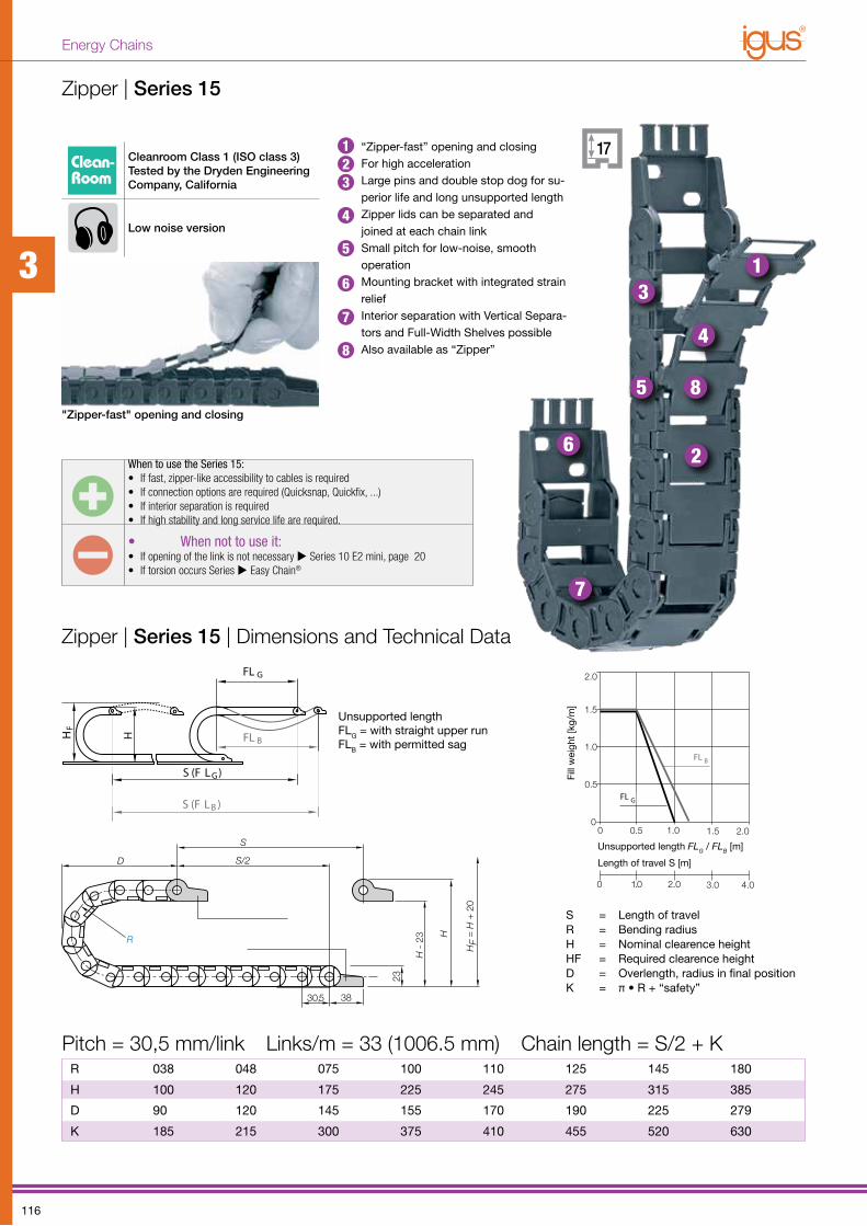
When to use the Series 15:• If fast, zipper-like accessibility to cables is required• If connection options are required (Quicksnap, Quickfix, ...)• If interior separation is required• If high stability and long service life are required.
• When not to use it:• If opening of the link is not necessary Series 10 E2 mini, page 20• If torsion occurs Series Easy Chain®
S = Length of travelR = Bending radiusH = Nominal clearence heightHF = Required clearence heightD = Overlength, radius in final positionK = π • R + “safety”
Zipper | Series 15
“Zipper-fast” opening and closingFor high accelerationLarge pins and double stop dog for su-perior life and long unsupported length Zipper lids can be separated and joined at each chain linkSmall pitch for low-noise, smooth operationMounting bracket with integrated strain reliefInterior separation with Vertical Separa-tors and Full-Width Shelves possibleAlso available as “Zipper”
"Zipper-fast" opening and closing
Zipper | Series 15 | Dimensions and Technical Data
Unsupported lengthFLG = with straight upper runFLB = with permitted sag
FL G
FL BH
HF
S (F L G)
S (F L B )
3830,5
H
H -
23
23
R
D S/2
S
HF
= H
+ 2
0
Pitch = 30,5 mm/link Links/m = 33 (1006.5 mm) Chain length = S/2 + K
1
2
3
4
5
6
7
8
3.0
0 0.5 2.0
0.5
1.0
2.0
1.5
0
FL G
FL B
Fill
wei
ght
[kg/
m]
Unsupported length FLG / FLB [m]
Length of travel S [m]
1.0
0 1.0 2.0 4.0
1.5
123
4
5
6
7
8
3
116
Energy Chains
2
5
110.X
153
155
5
7,5
7,5
1,5
8
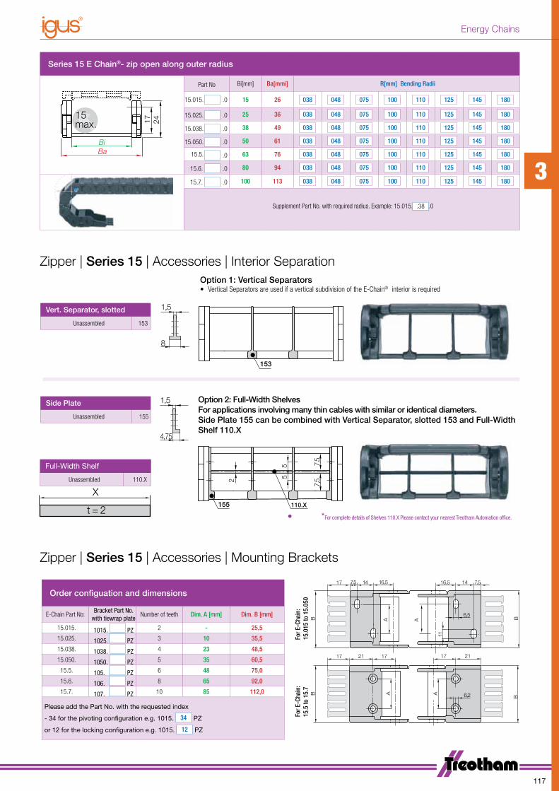
Series 15 E Chain®- zip open along outer radius
24
17
Ba
Bi
15
max.
Part No Bi[mm] Ba[mmi] R[mm] Bending Radii
15.015. .0 15 26 038 048 075 100 110 125 145 180
15.025. .0 25 36 038 048 075 100 110 125 145 180
15.038. .0 38 49 038 048 075 100 110 125 145 180
15.050. .0 50 61 038 048 075 100 110 125 145 180
15.5. .0 63 76 038 048 075 100 110 125 145 180
15.6. .0 80 94 038 048 075 100 110 125 145 180
15.7. .0 100 113 038 048 075 100 110 125 145 180
Supplement Part No. with required radius. Example: 15.015. .38 .0
Zipper | Series 15 | Accessories | Interior Separation
B A
17 211721
6,2A
B
AB
16,5 14 7,516,5147,5
11
BA
6,5
17
17
For E
-Cha
in:
15.0
15 to
15.
050
For E
-Cha
in:
15.5
to 1
5.7
Order configuation and dimensions
E-Chain Part No:Bracket Part No.
with tiewrap plateNumber of teeth Dim. A [mm] Dim. B [mm]
15.015. 1015. PZ 2 - 25,5
15.025. 1025. PZ 3 10 35,5
15.038. 1038. PZ 4 23 48,5
15.050. 1050. PZ 5 35 60,5
15.5. 105. PZ 6 48 75,0
15.6. 106. PZ 8 65 92,0
15.7. 107. PZ 10 85 112,0
Please add the Part No. with the requested index
- 34 for the pivoting configuration e.g. 1015. 34 PZ
or 12 for the locking configuration e.g. 1015. 12 PZ
Vert. Separator, slotted
Unassembled 153
2
5
110.X
153
155
5
7,5
7,5
Option 2: Full-Width Shelves For applications involving many thin cables with similar or identical diameters.Side Plate 155 can be combined with Vertical Separator, slotted 153 and Full-Width Shelf 110.X
X
t = 2
1,5
4,75
Side Plate
Unassembled 155
Full-Width Shelf
Unassembled 110.X
RR
Option 1: Vertical Separators• Vertical Separators are used if a vertical subdivision of the E-Chain® interior is required
Zipper | Series 15 | Accessories | Mounting Brackets
• *For complete details of Shelves 110.X Please contact your nearest Treotham Automation office.
3
117
Energy Chains
R
30.3
4
30
D S/2
S
36
H
7
H - 36
HF = H + 20
Moving End
Fixed End
FLG
FLBH
HF
S (FLG)
S (FLB)
0.5
1.5
0
1.0
0 0.5 1.0 2.01.5
0 1 2 43
FLB
FLG
Fill
weig
ht
[kg/m
]
Unsupported length FLG / FLB [m]
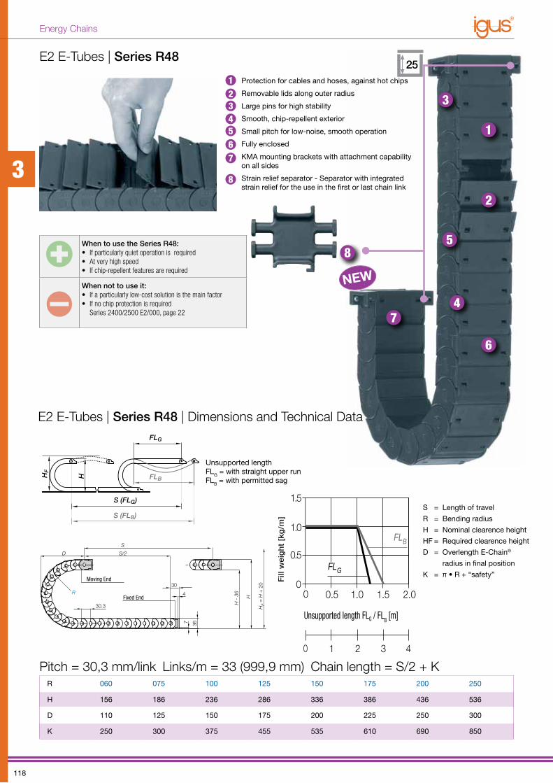
When to use the Series R48:• If particularly quiet operation is required• At very high speed• If chip-repellent features are required
When not to use it:• If a particularly low-cost solution is the main factor• If no chip protection is required
Series 2400/2500 E2/000, page 22
R 060 075 100 125 150 175 200 250
H 156 186 236 286 336 386 436 536
D 110 125 150 175 200 225 250 300
K 250 300 375 455 535 610 690 850
E2 E-Tubes | Series R4825
1
2
3
4
5
6
7
8
NEW
Unsupported lengthFLG = with straight upper runFLB = with permitted sag
S = Length of travel
R = Bending radius
H = Nominal clearence height
HF = Required clearence height
D = Overlength E-Chain®
radius in final position
K = π • R + “safety”
Pitch = 30,3 mm/link Links/m = 33 (999,9 mm) Chain length = S/2 + K
1234567
8
E2 E-Tubes | Series R48 | Dimensions and Technical Data
Protection for cables and hoses, against hot chips
Removable lids along outer radius
Large pins for high stability
Smooth, chip-repellent exterior
Small pitch for low-noise, smooth operation
Fully enclosed
KMA mounting brackets with attachment capability on all sides
Strain relief separator - Separator with integrated strain relief for the use in the first or last chain link
3
118
Energy Chains
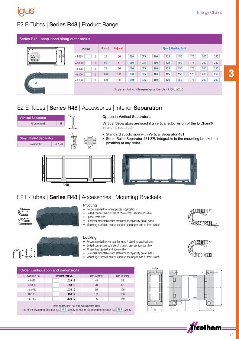
Series R48 - snap-open along outer radius
25
36
22
max.
Ba
Bi
Part No Bi[mm] Ba[mmi] R[mm] Bending Radii
48.025. .0 25 36 060 075 100 125 150 175 200 250
48.050. .0 50 61 060 075 100 125 150 175 200 250
48.075. .0 75 86 060 075 100 125 150 175 200 250
48.100. .0 100 111 060 075 100 125 150 175 200 250
48.130. .0 130 141 060 075 100 125 150 175 200 250
Supplement Part No. with required radius. Example: 48.100. 100 .0
Vertical Separator
Unassembled 481
Strain Relief Separator
Unassembled 481.ZR
Order configuation and dimensions
E-Chain Part No. Bracket Part No. Dim. A [mm] Dim. B [mm]
48.025 .025.12 45 55
48.050 .050.12 70 80
48.075. .075.12 95 105
48.100. .100.12 120 130
48.130. .130.12 150 160
Please add the Part No. with the requested index - 480 for the pivoting configuration e.g. 480 .025.12 or 485 for the locking configuration e.g. 485 .025.12
RR
5
BA
5
9 9
5
18
36 30 27,5
E2 E-Tubes | Series R48 | Accessories | Interior Separation
E2 E-Tubes | Series R48 | Product Range
Option 1: Vertical Separators
Vertical Separators are used if a vertical subdivision of the E-Chain® interior is required -
• Standard subdivision with Vertical Separator 481• Strain Relief Separator 481.ZR, integrable in the mounting bracket, to
postition at any point.
2,5
8
3,5
10 10
3,5
10 10
481
E2 E-Tubes | Series R48 | Accessories | Mounting BracketsPivoting• Recommended for unsupported applications• Bolted connection outside of chain cross-section possible• Space-restricted• Universal mountable with attachment capability on all sides• Mounting-surfaces can be used on the upper side or front-sided
Locking• Recommended for vertical hanging / standing applications• Bolted connection outside of chain cross-section possible• At very high speed and acceleration• Universal mountable with attachment capability on all sides• Mounting-surfaces can be used on the upper side or front-sided
25°
7°
7°
25°
45°
45°
7°-29° 7°-29°
25°
7°
7°
25°
45°
45°
7°-29° 7°-29°
3
119
Energy Chains
10,5
FLG
FLB
H
HF
S (FLG)
S (FLB)
0 0.25 0.50 0.75
0.25
0.50
0.75
0 0.5 1.0 1.5
0
FLG
FLB
Unsupported length FLG [m]
Fill
wei
ght [
kg/m
]
/FLB
S/2
20 22
S
R+3
H -
15
15
H
D
HF = H +
10
Moving End
Fixed End
S = Length of travel
R = Bending radius
H = Nominal clearence height
HF = Required clearence height
D = Overlength E-Chain®
radius in final position
K = π • R + “safety”
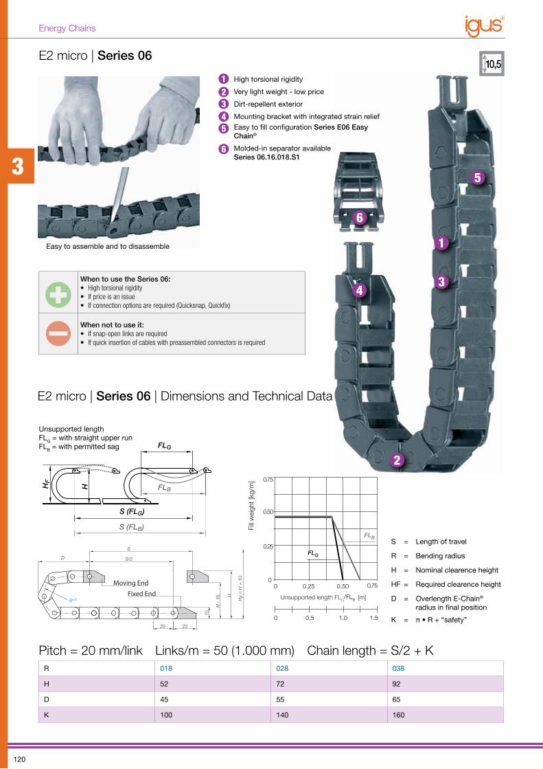
When to use the Series 06:• High torsional rigidity• If price is an issue• If connection options are required (Quicksnap, Quickfix)
When not to use it:• If snap-open links are required• If quick insertion of cables with preassembled connectors is required
R 018 028 038
H 52 72 92
D 45 55 65
K 100 140 160
E2 micro | Series 06 | Dimensions and Technical Data
Easy to assemble and to disassemble
High torsional rigidity
Very light weight - low price
Dirt-repellent exterior
Mounting bracket with integrated strain reliefEasy to fill configuration Series E06 Easy Chain®
Molded-in separator available Series 06.16.018.S1
1
2
34
5
6
Unsupported lengthFLG = with straight upper runFLB = with permitted sag
Pitch = 20 mm/link Links/m = 50 (1.000 mm) Chain length = S/2 + K
E2 micro | Series 06
12345
6
3
120
Energy Chains
B
10 8 41084
A BA
3,2
5,8/90° 5,8/90°
3,2
17
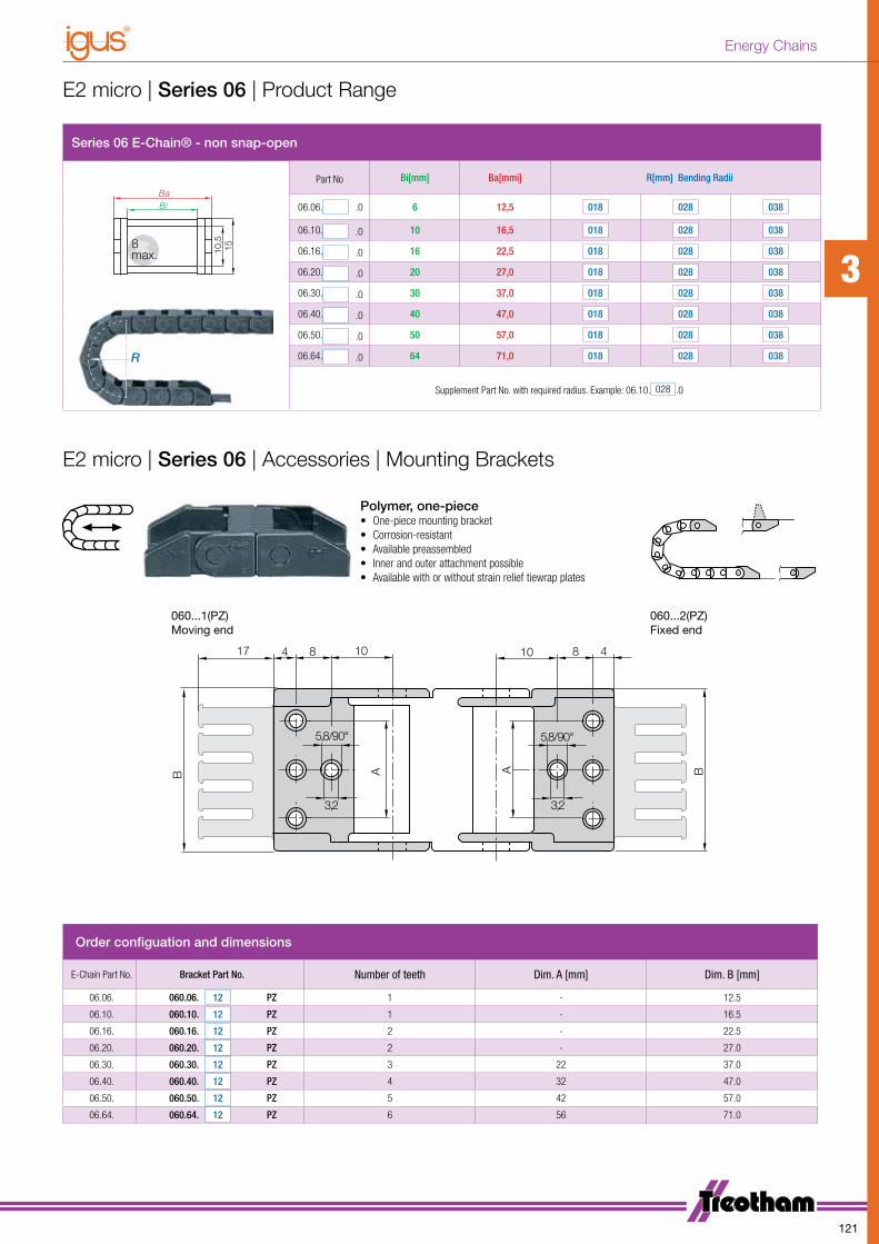
Series 06 E-Chain® - non snap-open
Bi
8max.
Ba
10,5
15
Part No Bi[mm] Ba[mmi] R[mm] Bending Radii
06.06. .0 6 12,5 018 028 038
06.10. .0 10 16,5 018 028 038
06.16. .0 16 22,5 018 028 038
06.20. .0 20 27,0 018 028 038
06.30. .0 30 37,0 018 028 038
06.40. .0 40 47,0 018 028 038
06.50. .0 50 57,0 018 028 038
06.64. .0 64 71,0 018 028 038
Supplement Part No. with required radius. Example: 06.10. 028 .0
RR
Order configuation and dimensions
E-Chain Part No. Bracket Part No. Number of teeth Dim. A [mm] Dim. B [mm]
06.06. 060.06. 12 PZ 1 - 12.5
06.10. 060.10. 12 PZ 1 - 16.5
06.16. 060.16. 12 PZ 2 - 22.5
06.20. 060.20. 12 PZ 2 - 27.0
06.30. 060.30. 12 PZ 3 22 37.0
06.40. 060.40. 12 PZ 4 32 47.0
06.50. 060.50. 12 PZ 5 42 57.0
06.64. 060.64. 12 PZ 6 56 71.0
E2 micro | Series 06 | Product Range
E2 micro | Series 06 | Accessories | Mounting Brackets
Polymer, one-piece• One-piece mounting bracket• Corrosion-resistant• Available preassembled• Inner and outer attachment possible• Available with or without strain relief tiewrap plates
060...1(PZ) 060...2(PZ)Moving end Fixed end
3
121
Energy Chains

FLG
FLB
H
HF
S (FLG)
S (FLB)
0 0.5 1.0 1.5
0.5
1.0
2.0
2.0
1.5
0
FLB
FLG
0 1.0 2.0 4.03.0
Length of travel S [m]
Unsupported length FLG I FLB [m]
Fill
wei
ght [
kg/m
]
3830,5
H
H - 23
23
R
D S/2
S
HF = H
+ 2
0Moving End
Fixed End
Clean-Room
Cleanroom Class 1 (ISO class 3) Tested by the Dryden Engineering Company, California
R 028 038 048 075 100 110 125 145 180
H 80 100 120 175 225 245 275 315 385
D 70 80 90 120 145 155 170 190 225
K 150 185 215 300 375 410 455 520 630
When to use the Series 10:• If opening is not necessary• If many connection options are required (Quicksnap, Quickfix)• If a small but very stable chain is required
When not to use it:• If extremely quick opening of the links is necessary
use Series 15 Zipper, page 14• If quick insertion of cables with preassembled connectors is required
S = Length of travel
R = Bending radius
H = Nominal clearence height
HF = Required clearence height
D = Overlength E-Chain
radius in final position
K = π • R + “safety”
1
2
3
4
5
67
E2 mini | Series 10
Easy to assemble and to disassemble
Large pins and double stop dog for superior life and long unsupported length
Mounting bracket with integrated strain relief
Dirt-repellent exterior
Interior separation available
One piece each link
Snap-open configuration Series 15 Zipper page, 14
Molded-in separator available Series 10.050.075.S
E2 mini | Series 10 | Dimensions and Technical Data
Unsupported lengthFLG = with straight upper runFLB = with permitted sag
Pitch = 30,5 mm/link Links/m = 33 (1.006,5 mm) Chain length = S/2 + K
18
1
23456
73
122
Energy Chains
AB
16,5 14 7,516,5147,5
11
BA
17
B A
17 211721
6,2A B
17
6,5
27ϒ
90ϒ
27ϒ 90ϒ
27ϒ
90ϒ
90ϒ
27ϒ
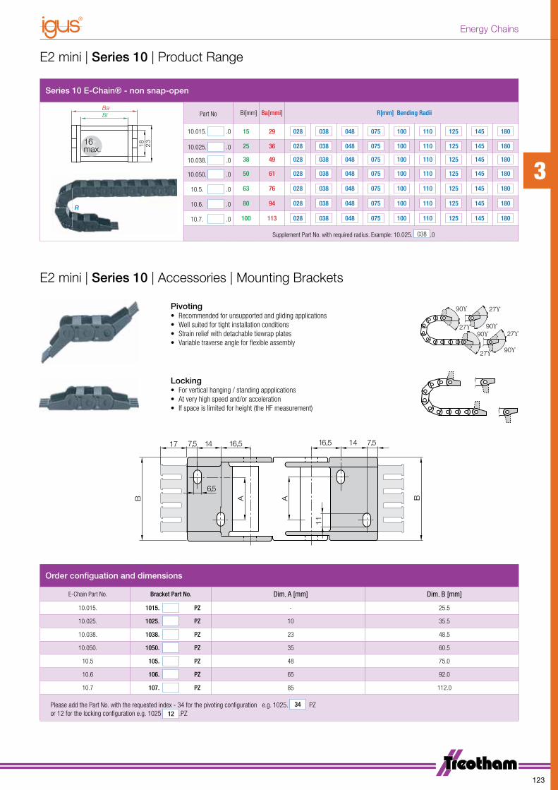
Series 10 E-Chain® - non snap-open
Bi
16
max.
Ba
18
23
Part No Bi[mm] Ba[mmi] R[mm] Bending Radii
10.015. .0 15 29 028 038 048 075 100 110 125 145 180
10.025. .0 25 36 028 038 048 075 100 110 125 145 180
10.038. .0 38 49 028 038 048 075 100 110 125 145 180
10.050. .0 50 61 028 038 048 075 100 110 125 145 180
10.5. .0 63 76 028 038 048 075 100 110 125 145 180
10.6. .0 80 94 028 038 048 075 100 110 125 145 180
10.7. .0 100 113 028 038 048 075 100 110 125 145 180
Supplement Part No. with required radius. Example: 10.025. 038 .0
RR
Order configuation and dimensions
E-Chain Part No. Bracket Part No. Dim. A [mm] Dim. B [mm]
10.015. 1015. PZ - 25.5
10.025. 1025. PZ 10 35.5
10.038. 1038. PZ 23 48.5
10.050. 1050. PZ 35 60.5
10.5 105. PZ 48 75.0
10.6 106. PZ 65 92.0
10.7 107. PZ 85 112.0
Please add the Part No. with the requested index - 34 for the pivoting configuration e.g. 1025. 34 PZ or 12 for the locking configuration e.g. 1025 12 .PZ
E2 mini | Series 10 | Product Range
E2 mini | Series 10 | Accessories | Mounting Brackets
Pivoting• Recommended for unsupported and gliding applications• Well suited for tight installation conditions• Strain relief with detachable tiewrap plates• Variable traverse angle for flexible assembly
Locking• For vertical hanging / standing appplications• At very high speed and/or acceleration• If space is limited for height (the HF measurement)
3
123
Energy Chains
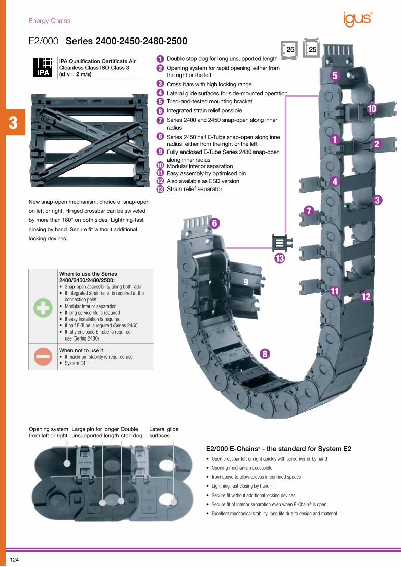
IPA Qualification Certificate Air Cleanless Class ISO Class 3 (at v = 2 m/s)
When to use the Series 2400/2450/2480/2500:• Snap-open accessibility along both radii• If integrated strain relief is required at the
connection point• Modular interior separation• If long service life is required• If easy installation is required• If half E-Tube is required (Series 2450)• If fully enclosed E-Tube is required
use (Series 2480)
When not to use it:• If maximum stability is required use• System E4.1
E2/000 E-Chains® - the standard for System E2• Open crossbar left or right quickly with scredriver or by hand
• Opening mechanism accessible
• from above to allow access in confined spaces
• Lightning-fast closing by hand -
• Secure fit without additional locking devices
• Secure fit of interior separa tion even when E-Chain® is open
• Excellent mechanical stability, long life due to design and material
Double stop dog
Opening system from left or right
Lateral glide surfaces
Large pin for longer unsup ported length
E2/000 | Series 2400·2450·2480·2500
1 2
3
4
5
67
8
9
10
11 12
13
New snap-open mechanism, choice of snap-open
on left or right. Hinged crossbar can be swiveled
by more than 180° on both sides. Lightning-fast
closing by hand. Secure fit without additional
locking devices.
25 25Double stop dog for long unsupported length
Opening system for rapid opening, either from the right or the left
Cross bars with high locking range
Lateral glide surfaces for side-mounted operationTried-and-tested mounting bracket
Integrated strain relief possible
Series 2400 and 2450 snap-open along inner radius
Series 2450 half E-Tube snap-open along inne radius, either from the right or the left Fully enclosed E-Tube Series 2480 snap-open along inner radiusModular interior separationEasy assembly by optimised pinAlso available as ESD versionStrain relief separator
111213
10
9
12
34567
83
124
Energy Chains
FLG
FLB
H
HF
S (FLG)
S (FLB)
0.5
1.5
0
1.0
0
2.0
5.0
0.5 1.0 2.01.5 2.5
4.0
0 1 2 43 5
FLG
FLB
Unsupported length FLG / FLB [m]
FIll
wei
ght [
kg/m
]Length of travel S [m]
D
H
H - 35R+6
46
S/2
S
35
HF = H + 25Mounting end
Fixed end
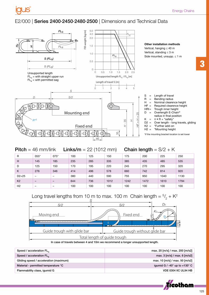
R 055* 075* 100 125 150 175 200 225 250
H 145 185 235 285 335 385 435 485 535
D 125 150 170 195 220 245 270 295 320
K 276 346 414 496 578 660 742 814 920
D2+25 – – 380 440 590 755 950 1040 1130
K2 – – 644 736 1012 1242 1472 1610 1794
H2 – – 100 100 100 100 100 100 100
Speed / acceleration FLG max. 20 [m/s] / max. 200 [m/s2]
Speed / acceleration FLB max. 3 [m/s] / max. 6 [m/s2]
Gliding speed / acceleration (maximum) max. 10 [m/s] / max. 50 [m/s2]
Material - permitted temperature °C igumid G / -40° up to +130° C
Flammability class, igumid G VDE 0304 IIC UL94 HB
SD22/S2/S
R
K2
HRI
H2Moving end Fixed end
Guide trough with glide bar
Total length of guide troughGuide trough without glide bar
Long travel lengths from 10 m to max. 100 m Chain length = S/2 + K2
In case of travels between 4 and 10m we recommend a longer unsupported length.
E2/000 | Series 2400·2450·2480·2500 | Dimensions and Technical Data
Pitch = 46 mm/link Links/m = 22 (1012 mm) Chain length = S/2 + K
S = Length of travelR = Bending radiusH = Nominal clearence heightHF = Required clearence heightHRI = Trough inner heightD = Overlength E-Chain®
radius in final positionK = π • R + "safety"D2 = Over length - long travels, glidingK2 = *Further add-onH2 = *Mounting height
*if the mounting bracket location is set lower
Other installation methodsVertical, hanging ≤ 40 mVertical, standing ≤ 3 mSide mounted, unsupp. ≤ 1 m
Unsupported lengthFLG = with straight upper runFLB = with permitted sag
3
125
Energy Chains

Series 2400 E-Chain® - snap-open along inner radius
Ba
Bi
25
35
23
max.
Ba
Bi
25
35
23
max.
Ba
Bi
25
3523
max.
Part No Bi[mm] Ba[mm] R[mm] Bending Radii
2400.02. .0 25 41 055 075 100 125 150 175 200 225 250
2400.03. .0 38 54 055 075 100 125 150 175 200 225 250
2400.05. .0 57 73 055 075 100 125 150 175 200 225 250
2400.07. .0 77 93 055 075 100 125 150 175 200 225 250
2400.09. .0 89 105 055 075 100 125 150 175 200 225 250
RR
2400.10. .0 103 119 055 075 100 125 150 175 200 225 250
2400.12. .0 125 141 055 075 100 125 150 175 200 225 250
Supplement Part No. with required radius. Example: 2400.03. 055 .0
Series 2500 - E-Chain® - snap-open along outer radius - Standard!
Ba
Bi
25
35
23
max.
Ba
Bi
25
35
23
max.
Ba
Bi
25
3523
max.
Part No Bi[mm] Ba[mmi] R[mm] Bending Radii
2500.02. .0 25 41 055 075 100 125 150 175 200 225 250
2500.03. .0 38 54 055 075 100 125 150 175 200 225 250
2500.05. .0 57 73 055 075 100 125 150 175 200 225 250
2500.07. .0 77 93 055 075 100 125 150 175 200 225 250
RR
2500.09. .0 89 105 055 075 100 125 150 175 200 225 250
2500.10. .0 103 119 055 075 100 125 150 175 200 225 250
2500.12. .0 125 141 055 075 100 125 150 175 200 225 250
Supplement Part No. with required radius. Example: 2500.03. 055 .0
E2/000 | E-Chains® | Series 2400·2500 | Product Range
3
126
Energy Chains

Series 2450 - half E-Tube - snap-open along inner radius
Ba
Bi
25
35
23
max.
Ba
Bi
25
35
23
max.
Ba
Bi
25
3523
max.
Part No Bi[mm] Ba[mmi] R[mm] Bending Radii
2450.02. .0 25 41 100 125 150 175 200 225 250
2450.03. .0 38 54 100 125 150 175 200 225 250
2450.05. .0 57 73 100 125 150 175 200 225 250
2450.07. .0 77 93 100 125 150 175 200 225 250
RR
2450.09. .0 89 105 100 125 150 175 200 225 250
2450.10. .0 103 119 100 125 150 175 200 225 250
2450.12. .0 125 141 100 125 150 175 200 225 250
Supplement Part No. with required radius. Example: 2450.03. 100 .0
Series 2480 - E-Tube - snap-open along inner radius
Ba
Bi
25
35
23
max.
Ba
Bi
25
35
23
max.
Ba
Bi
25
3523
max.
Part No Bi[mm] Ba[mmi] R[mm] Bending Radii
2480.02. .0 25 41 100 125 150 175 200 225 250
2480.03. .0 38 54 100 125 150 175 200 225 250
2480.05. .0 57 73 100 125 150 175 200 225 250
2480.07. .0 77 93 100 125 150 175 200 225 250
RR
2480.09. .0 89 105 100 125 150 175 200 225 250
2480.10. .0 103 119 100 125 150 175 200 225 250
2480.12. .0 125 141 100 125 150 175 200 225 250
Supplement Part No. with required radius. Example: 2480.03. 100 .0
E2/000 | E-Chains® | Series 2400·2500 | Product Range
3
127
Energy Chains
11,25
2,5
5 11,25
X - 7
5
11,25
2030
220.X
5
202
5
20202040
2,5
11,25
201.28*205.09* 201
203
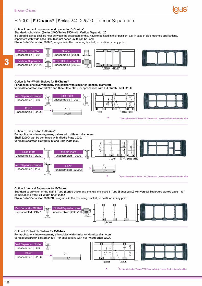
E2/000 | E-Chains® | Series 2400·2500 | Interior Separation
Option 1: Vertical Separators and Spacer for E-Chains®
Standard: subdivision (Series 2400/Series 2500) with Vertical Separator 201If a broad distance shall be kept between the separators or they have to be fixed in their position, e.g. in case of side mounted applications, separators with wide base 201.28 or (not series 2500) can be used.Strain Relief Separator 2020.Z, integrable in the mounting bracket, to postition at any point
Option 2: Full-Width Shelves for E-Chains®
For applications involving many thin cables with similar or identical diametersVertical Separator, slotted 202 and Side Plate 203 - for applications with Full-Width Shelf 220.X
Option 3: Shelves for E-Chains®
For applications involving many cables with different diameters. Shelf 2200.X can be combined with Middle Plate 2020, Vertical Separator, slotted 2040 and Side Plate 2030
Option 4: Vertical Separators for E-TubesStandard subdivision of the half E-Tube (Series 2450) and the fully enclosed E-Tube (Series 2480) with Vertical Separator, slotted 24051, for combinations with Full-Width Shelf 220.XStrain Relief Separator 2020.ZR, integrable in the mounting bracket, to postition at any point
Option 5: Full-Width Shelves for E-TubesFor applications involving many thin cables with similar or identical diametersVertical Separator, slotted 24501 - for applications with Full-Width Shelf 220.X
X - 1
t = 2,5
10
26
4
7
Vert. Separator, slottedunassembled 2040
Shelfunassembled 2200.X
Slide Plateunassembled 2030
Middle Plateunassembled 2020
11,25
2,5
5 11,25
220.X
5
24501
24501
Vert Separator Slottedunassembled 262
Shelf*unassembled 220.X
• *For complete details of Shelves 220.X Please contact your nearest Treotham Automation office.
XX - 7t = 2,5
11,25
2,5
5 11,25
X - 7
5
11,25
2030
220.X
5
2025
20202040
2,5
11,25
201.28*205.09* 201
203
Vertical Separatorunassembled 201
Vertical Separatorunassembled 201.28
Strain Relief Separatorunassembled 2020.Z
Spacer*unassembled 205.09
2
102
28
10
20 30 40109 128
11,25
2,5
5 11,25
X - 7
5
11,25
2030
220.X5
202
5
20202040
2,5
11,25
201.28*205.09* 201
203
X - 1
t = 2,5
10
26
4
7
Vert. Separator, slottedunassembled 202
Side Plateunassembled 203
Shelf*unassembled 220.X
2
10
6
4
6
2
4
7
2,5
10
4
10
11,25
2,5
5 11,25
220.X
5
24501
24501
Vert Separator Slottedunassembled 24501
Slotted Separator openunassembled 2020ZR
25
10
• *For complete details of Shelves 220.X Please contact your nearest Treotham Automation office.
• *For complete details of Shelves 2200.X Please contact your nearest Treotham Automation office.
25
10
4
10 10
4
10 10
3
128
Energy Chains
Part No.structure (Locking)
Selected chain type
Full set locking
With or without tiewrap plates
2020. 12 PZB+
Part No.structure (Pivoting)
Selected chain type
Full set pivoting
With or without tiewrap plates
2020. 34 PZB+
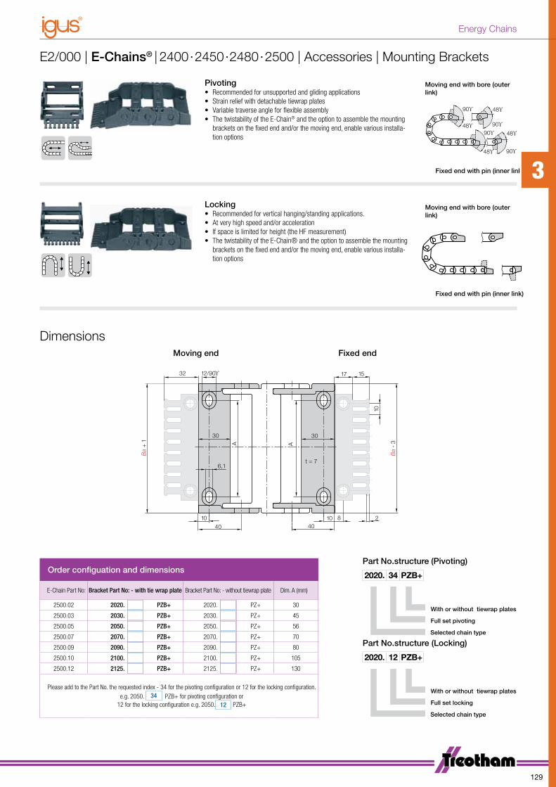
E2/000 | E-Chains® | 2400·2450·2480·2500 | Accessories | Mounting Brackets
Dimensions
1710
Ba
- 3A
40
30
15
40
6,1
30
t = 7
12/90ϒ
Ba
+ 1
81010 2
A
32
Moving end Fixed end
Pivoting• Recommended for unsupported and gliding applications• Strain relief with detachable tiewrap plates• Variable traverse angle for flexible assembly• The twistability of the E-Chain® and the option to assemble the mounting
brackets on the fixed end and/or the moving end, enable various installa-tion options
Locking• Recommended for vertical hanging/standing applications.• At very high speed and/or acceleration• If space is limited for height (the HF measurement) • The twistability of the E-Chain® and the option to assemble the mounting
brackets on the fixed end and/or the moving end, enable various installa-tion options
Moving end with bore (outer link)
48ϒ
90ϒ
48ϒ
90ϒ 48ϒ
48ϒ
90ϒ
90ϒ
Fixed end with pin (inner link)
Moving end with bore (outer link)
48ϒ
90ϒ
48ϒ
90ϒ 48ϒ
48ϒ
90ϒ
90ϒ
Fixed end with pin (inner link)
Order configuation and dimensions
E-Chain Part No: Bracket Part No: - with tie wrap plate Bracket Part No: - without tiewrap plate Dim. A (mm)
2500.02 2020. PZB+ 2020. PZ+ 30
2500.03 2030. PZB+ 2030. PZ+ 45
2500.05 2050. PZB+ 2050. PZ+ 56
2500.07 2070. PZB+ 2070. PZ+ 70
2500.09 2090. PZB+ 2090. PZ+ 80
2500.10 2100. PZB+ 2100. PZ+ 105
2500.12 2125. PZB+ 2125. PZ+ 130
Please add to the Part No. the requested index - 34 for the pivoting configuration or 12 for the locking configuration.e.g. 2050. 34 PZB+ for pivoting configuration or
12 for the locking configuration e.g. 2050. 12 PZB+
3
129
Energy Chains

E2/000 | Series 2600·2650·2680·2700
New snap-open mechanism, choice of snap-
open on left or right. Hinged crossbar can be
swiveled by more than 180° on both sides.
Lightning-fast closing by hand. Secure fit without
additional locking devices.
Ready Chain “Basic”Simlpe, prefabricated E-Chain System® including
assembled cables without connectors, labelled
according to you specifications.
Ready Chain “Standard”Simlpe, prefabricated E-ChainSystem® including as-
sembled cables with all connectors, labelled according
to your specifications.
Ready Chain “Premium”A prefabricated E-ChainSystem® with cables of all kinds,
as well as plugs, connectors and components according
to your specifications. Special shafts and plain bearings
machined according to your specifications.
Opening system for rapid opening, either from the right or the left
Double stop dog for long unsupported length
Cross bars with high locking range
Lateral glide surfaces for side-mounted operation
Tried-and-tested mounting bracket
Integrated strain relief possible
Half E-Tube Series 2650
Series 2600 and 2650 snap-open along inner radius
Fully enclosed E-Tube Series 2680
Modular interior separation
Easy assembly by optimized pin
Also available as ESD version
Strain relief separator - Separator with integrated strain relief.
1
2
3
4
5
6
7
8
10
12
13
11
9
When to use the Series 2600/2650/2680/2700:• Snap-open accessibility along both radii• If integrated strain relief is required at the
connection point• Modular interior separation• If long service life is required• If easy installation is required• If half E-Tube is required (Series 2650)• If fully enclosed E-Tube is required use
(Series 2680)
When not to use it:• If maximum stability is required• If the application is very simple• E-Tubes with small bending radii 075
Ready Chain | Fully Harnessed Energy Chains
*Ready Chains are available throughout the entire range of Energy Chains. Please contact your nearest Treotham Office for further details.
111213
109
1
23456783
130
Energy Chains
FLG
FLB
H
HF
S (FLG)
S (FLB) 1.0
3.0
0
2.0
0 1.0 2.0 3.0 4.0
6.0
7.0
9.0
8.0
0 2 4 86
4.0
5.0
FLB
FLG
Unsupported Length FLG/FLB (m)
Fill
Wei
ght (
kg/m
)
Length of travel S [m]
D
H
H -50R
+6
56
S/2
S
50
HF =
H +
35
SD22/S2/S
R
K2
HRI
H2Moving end Fixed end
Guide trough with glide bar
Total length of guide troughGuide trough without glide bar
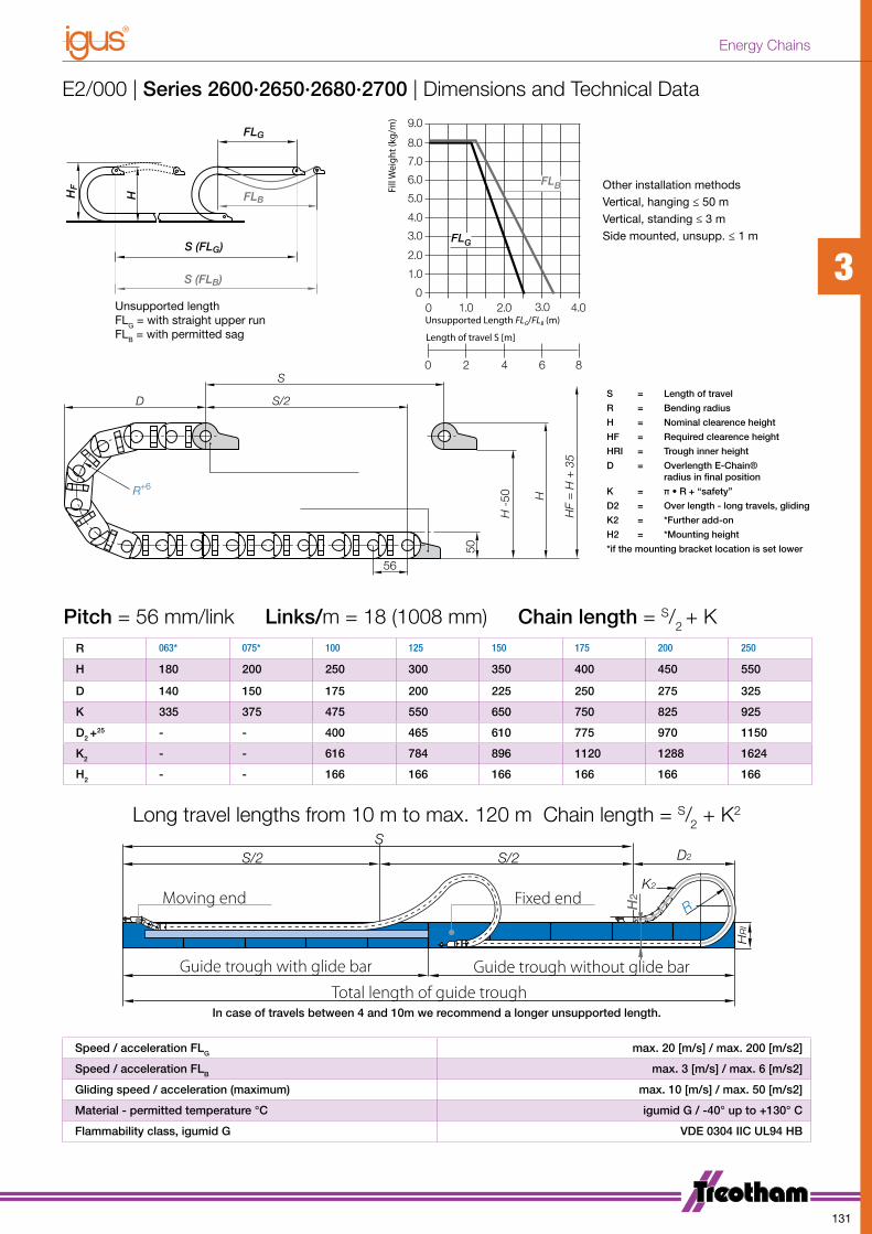
Speed / acceleration FLG max. 20 [m/s] / max. 200 [m/s2]
Speed / acceleration FLB max. 3 [m/s] / max. 6 [m/s2]
Gliding speed / acceleration (maximum) max. 10 [m/s] / max. 50 [m/s2]
Material - permitted temperature °C igumid G / -40° up to +130° C
Flammability class, igumid G VDE 0304 IIC UL94 HB
R 063* 075* 100 125 150 175 200 250
H 180 200 250 300 350 400 450 550
D 140 150 175 200 225 250 275 325
K 335 375 475 550 650 750 825 925
D2 +25 - - 400 465 610 775 970 1150
K2 - - 616 784 896 1120 1288 1624
H2 - - 166 166 166 166 166 166
Pitch = 56 mm/link Links/m = 18 (1008 mm) Chain length = S/2 + K
E2/000 | Series 2600·2650·2680·2700 | Dimensions and Technical Data
S = Length of travel
R = Bending radius
H = Nominal clearence height
HF = Required clearence height
HRI = Trough inner height
D = Overlength E-Chain® radius in final position
K = π • R + “safety”
D2 = Over length - long travels, gliding
K2 = *Further add-on
H2 = *Mounting height
*if the mounting bracket location is set lower
Other installation methodsVertical, hanging ≤ 50 mVertical, standing ≤ 3 mSide mounted, unsupp. ≤ 1 m
Long travel lengths from 10 m to max. 120 m Chain length = S/2 + K2
In case of travels between 4 and 10m we recommend a longer unsupported length.
Unsupported lengthFLG = with straight upper runFLB = with permitted sag
3
131
Energy Chains

Series 2600 - E-Chain® - snap-open along inner radius
Ba
Bi
35
5032
max.
Ba
Bi
35
50
32
max.
Ba
Bi
35
5032
max.
Part No Bi[mm] Ba[mmi] R[mm] Bending Radii
2600.05 .0 50 66 063 075 100 125 150 175 200 250
2600.06. .0 65 81 063 075 100 125 150 175 200 250
2600.07. .0 75 91 063 075 100 125 150 175 200 250
2600.09. .0 90 106 063 075 100 125 150 175 200 250
RR
2600.10. .0 100 116 063 075 100 125 150 175 200 250
2600.12. .0 125 141 063 075 100 125 150 175 200 250
2600.15. .0 150 166 063 075 100 125 150 175 200 250
2600.17. .0 175 194 063 075 100 125 150 175 200 250
Supplement Part No. with required radius. Example: 2600.05. 063 .0
Series 2700 - E-Chain® - snap-open along outer radius - Standard!
Ba
Bi
35
5032
max.
Ba
Bi
35
50
32
max.
Ba
Bi
35
5032
max.
Part No Bi[mm] Ba[mmi] R[mm] Bending Radii
2700.05 .0 50 66 063 075 100 125 150 175 200 250
2700.06. .0 65 81 063 075 100 125 150 175 200 250
2700.07. .0 75 91 063 075 100 125 150 175 200 250
2700.09. .0 90 106 063 075 100 125 150 175 200 250
RR
2700.10. .0 100 116 063 075 100 125 150 175 200 250
2700.12. .0 125 141 063 075 100 125 150 175 200 250
2700.15. .0 150 166 063 075 100 125 150 175 200 250
2700.17. .0 175 194 063 075 100 125 150 175 200 250
Supplement Part No. with required radius. Example: 2700.05. 063 .0
E2/000 | E-Chains® | Series 2600·2700 | Product Range
3
132
Energy Chains

Series 2650 - half E-Tube - snap-open along inner radius
Ba
Bi
35
5032
max.
Ba
Bi
35
50
32
max.
Ba
Bi
35
5032
max.
Part No Bi[mm] Ba[mmi] R[mm] Bending Radii
2650.05 .0 50 66 100 125 150 175 200 250
2650.06. .0 65 81 100 125 150 175 200 250
2650.07. .0 75 91 100 125 150 175 200 250
2650.09. .0 90 106 100 125 150 175 200 250
RR
2650.10. .0 100 116 100 125 150 175 200 250
2650.12. .0 125 141 100 125 150 175 200 250
2650.15. .0 150 166 100 125 150 175 200 250
2650.17. .0 175 194 100 125 150 175 200 250
Supplement Part No. with required radius. Example: 2650.05. 100 .0
Series 2680 - E-Tube - snap-open along inner radius
Ba
Bi
35
5032
max.
Ba
Bi
35
50
32
max.
Ba
Bi
35
5032
max.
Part No Bi[mm] Ba[mmi] R[mm] Bending Radii
2680.05 .0 50 66 100 125 150 175 200 250
2680.06. .0 65 81 100 125 150 175 200 250
2680.07. .0 75 91 100 125 150 175 200 250
2680.09. .0 90 106 100 125 150 175 200 250
RR
2680.10. .0 100 116 100 125 150 175 200 250
2680.12. .0 125 141 100 125 150 175 200 250
2680.15. .0 150 166 100 125 150 175 200 250
2680.17. .0 175 194 100 125 150 175 200 250
Supplement Part No. with required radius. Example: 2680.05. 100 .0
E2/000 | E-Tubes | Series 2650·2680 | Product Range
3
133
Energy Chains

16,2
5
268220.X
2,5
5 16,2
5
55
5
X - 7
6,25
7,5
266 2200.X
5
2,5
16,2
516
,25
264
55
5
205.09260.24
262
260
276
16,2
5
268220.X
2,5
5 16,2
5
55
5
X - 7
6,25
7,5
266 2200.X
5
2,5
16,2
516
,25
264
55
5
205.09260.24
262
260
276
16,2
5
268220.X
2,5
5 16,2
5
55
5
X - 7
6,25
7,5
266 2200.X
5
2,5
16,2
516
,25
264
55
5
205.09260.24
262
260
27616
,25
26501220.X
2,5
5
16,2
5
55
X - 7
6,25
7,5
2200.X
2,5
16,2
516
,25
5
26501
26501
276
16,2
5
26501220.X
2,5
5
16,2
5
55
X - 7
6,25
7,5
2200.X
2,5
16,2
516
,25
5
26501
26501
276
16,25
26511221.X
2,5
5
16,25
55
X - 7
6,25
7,5
2200.X
2,5
16,25
16,25
5
26501
26511
276
XX - 7
t = 2,5
E2/000 | E-Chains® | Series 2600·2700 | Interior Separation
Option 1: Vertical Separators and Spacer for E-Chains®
• Standard subdivision (Series 2600/Series 2700) with Vertical Separator 260, for combinations with Full-Width Shelf 220.X• If a broad distance shall be kept between the separators or they have to be fixed in their position, e.g. in case of side mounted applications, separators with wide base 260.24 or
Spacer 205.09 can be used• Strain Relief Separator 262.Z, integrable in the mounting bracket, to postition at any point
Option 2: Full-Width Shelves for E-Chains®
• For applications involving many thin cables with similar or identical diameters• Vertical Separator, slotted 268 - for applications with Full-Width Shelf 220.X
Option 3: Shelves for E-Chains®
• For applications involving many cables with different diameters.• Shelf 2200.X can be combined with Middle Plate 262, Slotted Separator 266 and Side Plate 264
Option 4: Vertical Separators for E-Tubes®
• Vertical Separators are used if a vertical subdivision of the • E-Tube interior is required.• Standard subdivision of the half E-Tube (Series 2650) and the fully
enclosed E-Tube (Series 2680)
Option 5: Full-Width Shelves for E-Tubes®
For applications involving many thin cables with similar or identical diameters• Vertical Separator, slotted 26501 - for applications with
Full-Width Shelf 220.X
Option 6: - Shelves for E-Tubes®
• For applications involving many cables with different diameters. • Shelf 2200.X can be combined with Vertical Separator, slotted 26501• Assembling of the Slotted Separator, open 276 in the existing separation
afterwards possible
Vertical Separator
unassembled 268
Full Width Shelf*
unassembled 220.X2,5
10
Vertical Separator, slottedunassembled 26501
4
6
12
Vertical Separator*
unassembled 260
3
12
Vertical Separator*
unassembled 260.24
3
24
Strain Relief Separator
unassembled 262.Z
4
10 10
Vertical Separator*
unassembled 205.09 20 30 40109 128
Middle Plate
unassembled 262
4
10
Slotted Separator
unassembled 266
Shelf*
unassembled 2200.X
2,5
10
2,5
10
Slide Plate
unassembled 264
4
7
Slotted Separator open
unassembled 276
2,5
10
Slotted Separator, open
unassembled 276
• *For complete details of Full Width Shelves 220.X Please contact your nearest Treotham Automation office.
• *For complete details of Full Width Shelves 220.X Please contact your nearest Treotham Automation office.
• *For complete details of Shelves 2200.X Please contact your nearest Treotham Automation office.
• *For complete details of Shelves 2200.X Please contact your nearest Treotham Automation office.
X - 1
t = 2,5
10
26
4
7
XX - 7t = 2,5
Shelf*
unassembled 2200.X
3
134
Energy Chains
Ba +
2A
54
40
54
A
6,1
40
t = 8Ba +
2
817 17 2
t = 8
16/90° 17 17
10
34
11
,5
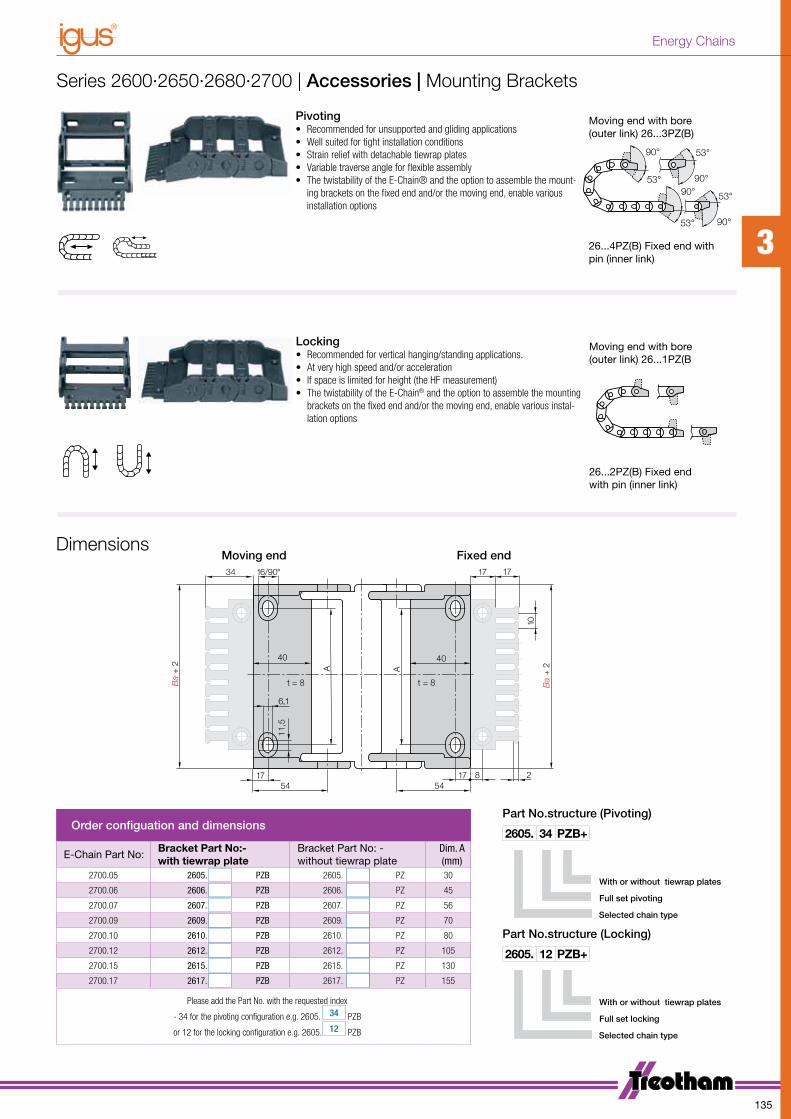
Order configuation and dimensions
E-Chain Part No:Bracket Part No:- with tiewrap plate
Bracket Part No: - without tiewrap plate
Dim. A(mm)
2700.05 2605. PZB 2605. PZ 30
2700.06 2606. PZB 2606. PZ 45
2700.07 2607. PZB 2607. PZ 56
2700.09 2609. PZB 2609. PZ 70
2700.10 2610. PZB 2610. PZ 80
2700.12 2612. PZB 2612. PZ 105
2700.15 2615. PZB 2615. PZ 130
2700.17 2617. PZB 2617. PZ 155
Please add the Part No. with the requested index
- 34 for the pivoting configuration e.g. 2605. 34 PZB
or 12 for the locking configuration e.g. 2605. 12 PZB
Part No.structure (Locking)
Selected chain type
Full set locking
With or without tiewrap plates
2605. 12 PZB+
Part No.structure (Pivoting)
Selected chain type
Full set pivoting
With or without tiewrap plates
2605. 34 PZB+
DimensionsMoving end Fixed end
Moving end with bore (outer link) 26...3PZ(B)
53°
90°
53°
90°53°
53°
90°
90°
26...4PZ(B) Fixed end with pin (inner link)
Moving end with bore (outer link) 26...1PZ(B
53°
90°
53°
90°53°
53°
90°
90°
26...2PZ(B) Fixed end with pin (inner link)
Series 2600·2650·2680·2700 | Accessories | Mounting Brackets
Pivoting• Recommended for unsupported and gliding applications• Well suited for tight installation conditions• Strain relief with detachable tiewrap plates• Variable traverse angle for flexible assembly• The twistability of the E-Chain® and the option to assemble the mount-
ing brackets on the fixed end and/or the moving end, enable various installation options
Locking• Recommended for vertical hanging/standing applications.• At very high speed and/or acceleration• If space is limited for height (the HF measurement) • The twistability of the E-Chain® and the option to assemble the mounting
brackets on the fixed end and/or the moving end, enable various instal-lation options
3
135
Energy Chains
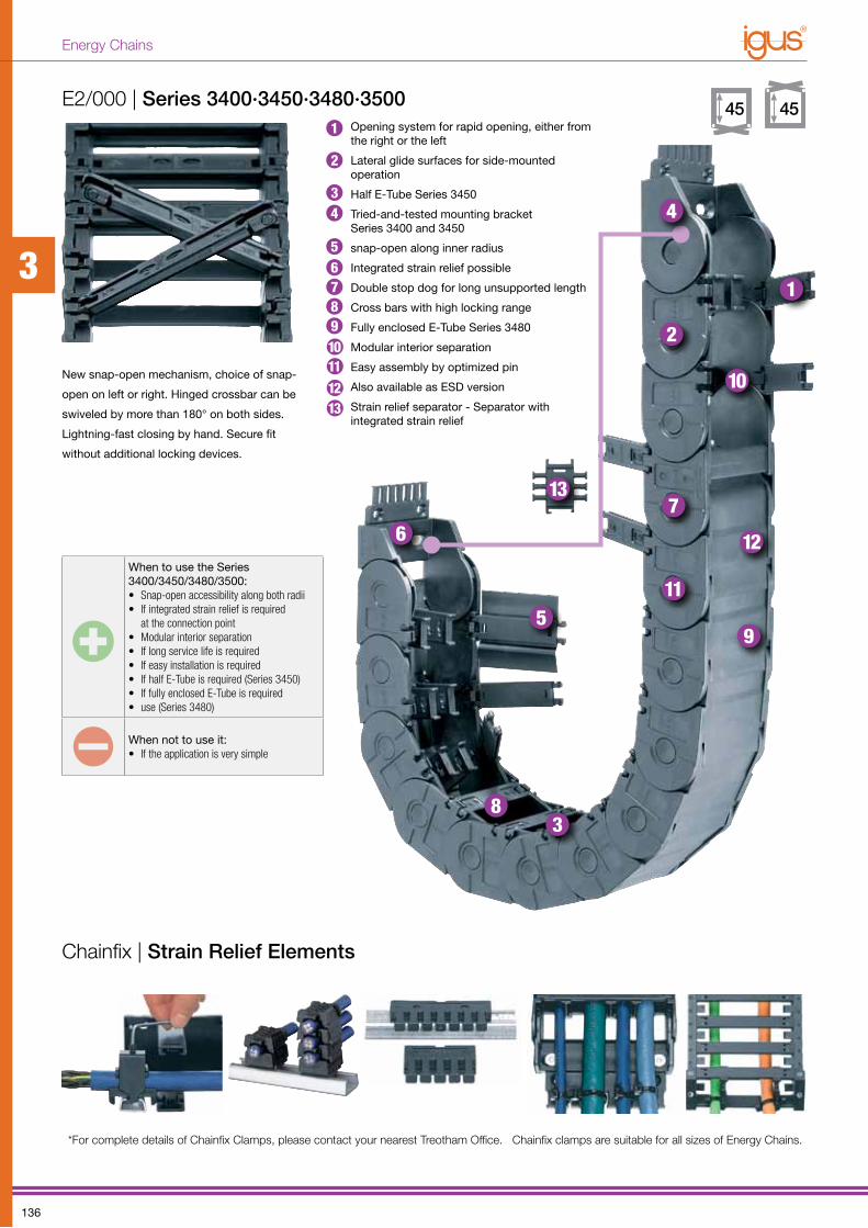
When to use the Series 3400/3450/3480/3500:• Snap-open accessibility along both radii• If integrated strain relief is required
at the connection point• Modular interior separation• If long service life is required• If easy installation is required• If half E-Tube is required (Series 3450)• If fully enclosed E-Tube is required • use (Series 3480)
When not to use it:• If the application is very simple
E2/000 | Series 3400·3450·3480·3500
Chainfix | Strain Relief Elements
New snap-open mechanism, choice of snap-
open on left or right. Hinged crossbar can be
swiveled by more than 180° on both sides.
Lightning-fast closing by hand. Secure fit
without additional locking devices.
Opening system for rapid opening, either from the right or the left
Lateral glide surfaces for side-mounted operation
Half E-Tube Series 3450
Tried-and-tested mounting bracketSeries 3400 and 3450
snap-open along inner radius
Integrated strain relief possible
Double stop dog for long unsupported length
Cross bars with high locking range
Fully enclosed E-Tube Series 3480
Modular interior separation
Easy assembly by optimized pin
Also available as ESD version
Strain relief separator - Separator with integrated strain relief
1
2
3
4
5
67
8
9
10
11
12
13
*For complete details of Chainfix Clamps, please contact your nearest Treotham Office. Chainfix clamps are suitable for all sizes of Energy Chains.
111213
109
1
2
34
5678
3
136
Energy Chains

FLG
FLB
1.0
3.0
0
2.0
0
4.0
8.0
1.0 2.0 4.03.0 5.0
6.0
12.010.0
0 2 4 86 10
13.0
Unsupported length FLG / FLB [m]
Length of travel S [m]
Fill
Wei
ght
(kg/
m)
FLG
FLB
H
HF
S (FLG)
S (FLB)
D
H
H -
64R+6
67
S/2
S
64
HF = H +
40Moving End
Fixed End
R 075* 100* 125 150 200 250 300
H 215 265 315 365 465 565 665
D 150 200 225 250 300 350 400
K 400 500 650 725 875 1050 1225
D2+25 – – 475 570 780 1010 1150
K2 – – 804 1005 1340 1675 1943
H2 – – 186 186 186 186 186
E2/000 | Series 3400·3450·3480·3500 | Dimensions and Technical Data
S = Length of travelR = Bending radiusH = Nominal clearence heightHF = Required clearence heightHRI = Trough inner heightD = Overlength E-Chain® radius in final positionK = π • R + "safety"D2 = Over length - long travels, glidingK2 = *Further add-onH2 = *Mounting height*if the mounting bracket location is set lower
Pitch = 67 mm/link Links/m = 15 (1005 mm) Chain length = S/2 + K
Long travel lengths from 10 m to max. 150 m Chain length = S/2 + K2S
D22/S2/S
R
K2
HRI
H2Moving End Fixed End
Guide trough with glide bar Guide trough without glide barTotal length of guide trough
Other installation methodsVertical, hanging ≤ 80 mVertical, standing ≤ 3 mSide mounted, unsupp. ≤ 1 m
In case of travels between 4 and 10m we recommend a longer unsupported length.
Speed / acceleration FLG max. 20 [m/s] / max. 200 [m/s2]
Speed / acceleration FLB max. 3 [m/s] / max. 6 [m/s2]
Gliding speed / acceleration (maximum) max. 10 [m/s] / max. 50 [m/s2]
Material - permitted temperature °C igumid G / -40° up to +130° C
Flammability class, igumid G VDE 0304 IIC UL94 HB
Unsupported lengthFLG = with straight upper runFLB = with permitted sag
3
137
Energy Chains
Series 3400 - E-Chain® - snap-open along inner radius
Ba
Bi
45
6442
max.
Ba
Bi
45
6442
max.
Ba
Bi
45
6442
max.
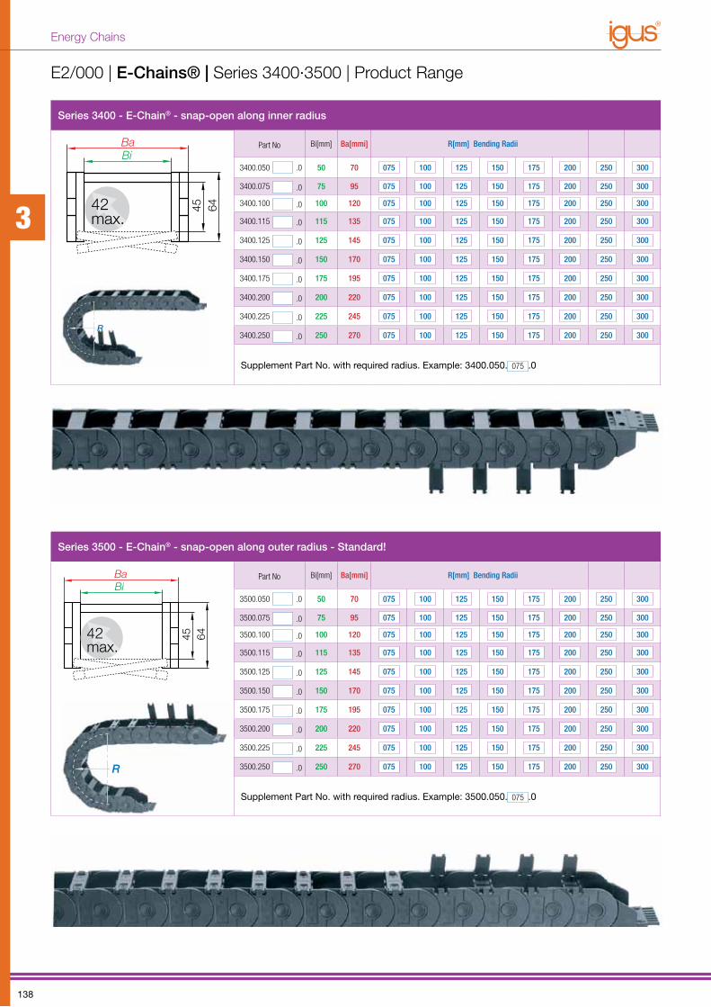
Part No Bi[mm] Ba[mmi] R[mm] Bending Radii
3400.050 .0 50 70 075 100 125 150 175 200 250 300
3400.075 .0 75 95 075 100 125 150 175 200 250 300
3400.100 .0 100 120 075 100 125 150 175 200 250 300
3400.115 .0 115 135 075 100 125 150 175 200 250 300
3400.125 .0 125 145 075 100 125 150 175 200 250 300
3400.150 .0 150 170 075 100 125 150 175 200 250 300
RR
3400.175 .0 175 195 075 100 125 150 175 200 250 300
3400.200 .0 200 220 075 100 125 150 175 200 250 300
3400.225 .0 225 245 075 100 125 150 175 200 250 300
3400.250 .0 250 270 075 100 125 150 175 200 250 300
Supplement Part No. with required radius. Example: 3400.050. 075 .0
Series 3500 - E-Chain® - snap-open along outer radius - Standard!
Ba
Bi
45
6442
max.
Ba
Bi
45
6442
max.
Ba
Bi
45
6442
max.
Part No Bi[mm] Ba[mmi] R[mm] Bending Radii
3500.050 .0 50 70 075 100 125 150 175 200 250 300
3500.075 .0 75 95 075 100 125 150 175 200 250 300
3500.100 .0 100 120 075 100 125 150 175 200 250 300
3500.115 .0 115 135 075 100 125 150 175 200 250 300
3500.125 .0 125 145 075 100 125 150 175 200 250 300
3500.150 .0 150 170 075 100 125 150 175 200 250 300
RR
3500.175 .0 175 195 075 100 125 150 175 200 250 300
3500.200 .0 200 220 075 100 125 150 175 200 250 300
3500.225 .0 225 245 075 100 125 150 175 200 250 300
3500.250 .0 250 270 075 100 125 150 175 200 250 300
Supplement Part No. with required radius. Example: 3500.050. 075 .0
E2/000 | E-Chains® | Series 3400·3500 | Product Range
3
138
Energy Chains
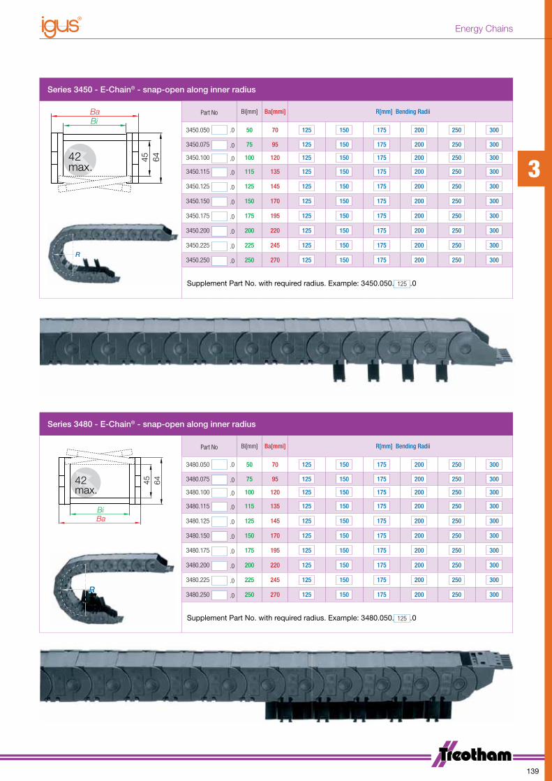
Series 3450 - E-Chain® - snap-open along inner radius
Ba
Bi
45
6442
max.
Ba
Bi
45
6442
max.
Ba
Bi
45
6442
max.
Part No Bi[mm] Ba[mmi] R[mm] Bending Radii
3450.050 .0 50 70 125 150 175 200 250 300
3450.075 .0 75 95 125 150 175 200 250 300
3450.100 .0 100 120 125 150 175 200 250 300
3450.115 .0 115 135 125 150 175 200 250 300
3450.125 .0 125 145 125 150 175 200 250 300
3450.150 .0 150 170 125 150 175 200 250 300
RR
3450.175 .0 175 195 125 150 175 200 250 300
3450.200 .0 200 220 125 150 175 200 250 300
3450.225 .0 225 245 125 150 175 200 250 300
3450.250 .0 250 270 125 150 175 200 250 300
Supplement Part No. with required radius. Example: 3450.050. 125 .0
Series 3480 - E-Chain® - snap-open along inner radius
Ba
Bi
45
6442
max.
Ba
Bi
45
6442
max.
Ba
Bi
45
6442
max.
Part No Bi[mm] Ba[mmi] R[mm] Bending Radii
3480.050 .0 50 70 125 150 175 200 250 300
3480.075 .0 75 95 125 150 175 200 250 300
3480.100 .0 100 120 125 150 175 200 250 300
3480.115 .0 115 135 125 150 175 200 250 300
3480.125 .0 125 145 125 150 175 200 250 300
3480.150 .0 150 170 125 150 175 200 250 300
RR
3480.175 .0 175 195 125 150 175 200 250 300
3480.200 .0 200 220 125 150 175 200 250 300
3480.225 .0 225 245 125 150 175 200 250 300
3480.250 .0 250 270 125 150 175 200 250 300
Supplement Part No. with required radius. Example: 3480.050. 125 .0
3
139
Energy Chains
16,252,
5
2200.X 303
301 305.12 305.08
22,5
21,2510
304 307
302302.24
20,80
3,4 12
12
320.X
20,80
34501
20,80
3,4 12
12
34501320.X
16,25
2200.X
22,5
21,25
34501
20,80
34501 307
2,5
34501
20,80
3,4 12
12
34501320.X
16,25
2200.X
22,5
21,25
34501
20,80
34501 307
2,5
34501
20,80
3,4 12
12
34501320.X
16,25
2200.X
22,5
21,25
34501
20,80
34501 307
2,5
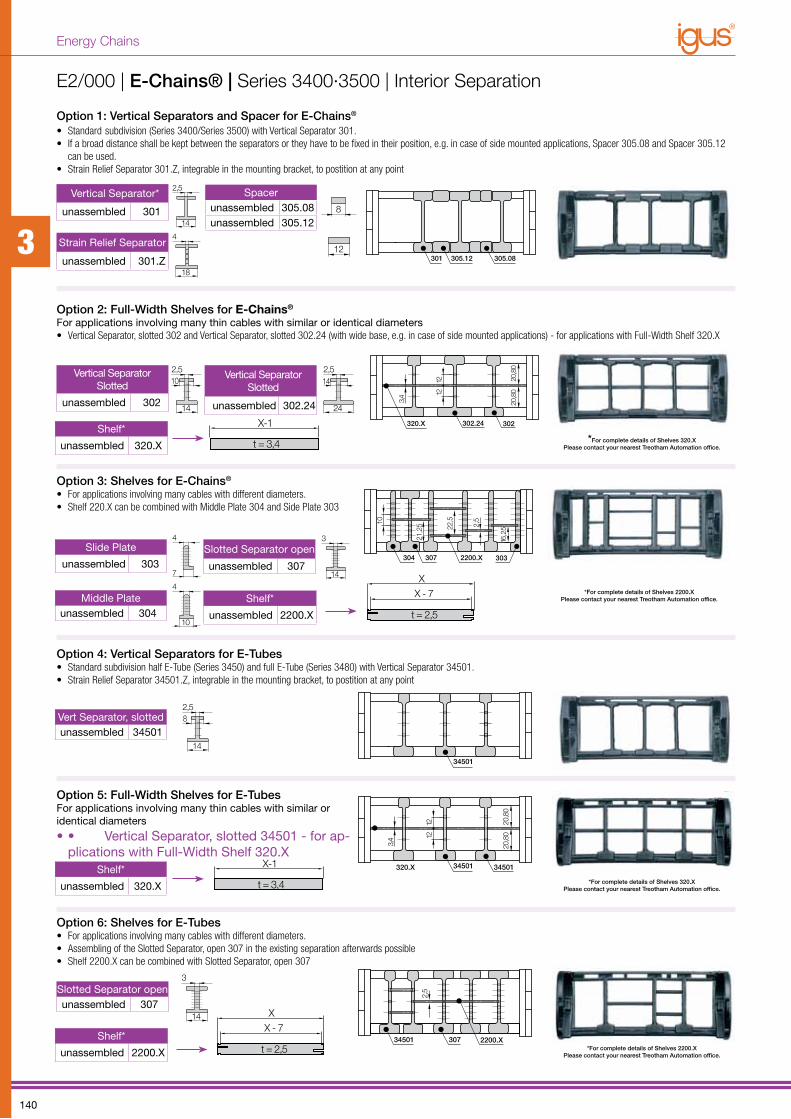
Option 1: Vertical Separators and Spacer for E-Chains®
• Standard subdivision (Series 3400/Series 3500) with Vertical Separator 301.• If a broad distance shall be kept between the separators or they have to be fixed in their position, e.g. in case of side mounted applications, Spacer 305.08 and Spacer 305.12
can be used.• Strain Relief Separator 301.Z, integrable in the mounting bracket, to postition at any point
Option 2: Full-Width Shelves for E-Chains®
For applications involving many thin cables with similar or identical diameters• Vertical Separator, slotted 302 and Vertical Separator, slotted 302.24 (with wide base, e.g. in case of side mounted applications) - for applications with Full-Width Shelf 320.X
Option 3: Shelves for E-Chains®
• For applications involving many cables with different diameters. • Shelf 220.X can be combined with Middle Plate 304 and Side Plate 303
Option 4: Vertical Separators for E-Tubes• Standard subdivision half E-Tube (Series 3450) and full E-Tube (Series 3480) with Vertical Separator 34501.• Strain Relief Separator 34501.Z, integrable in the mounting bracket, to postition at any point
Option 5: Full-Width Shelves for E-TubesFor applications involving many thin cables with similar or identical diameters
• • Vertical Separator, slotted 34501 - for ap-plications with Full-Width Shelf 320.X
Option 6: Shelves for E-Tubes• For applications involving many cables with different diameters. • Assembling of the Slotted Separator, open 307 in the existing separation afterwards possible• Shelf 2200.X can be combined with Slotted Separator, open 307
Vertical Separator Slotted
unassembled 302
2,5
10
14
Vertical Separator Slotted
unassembled 302.24
2,5
14
24
Vert Separator, slottedunassembled 34501
2,5
8
14
16,252,
5
2200.X 303
301 305.12 305.08
22,5
21,2510
304 307
302302.24
20,80
3,4 12
12
320.X
20,80
Vertical Separator*
unassembled 301
2,5
14
Spacerunassembled 305.08unassembled 305.12
4
18 13
Strain Relief Separator
unassembled 301.Z
20 30 40109 128
20 30 40109 128
16,252,
5
2200.X 303
301 305.12 305.08
22,5
21,2510
304 307
302302.24
20,80
3,4 12
12320.X
20,80
Middle Plateunassembled 304
4
7
4
10
3
14
Slide Plate
unassembled 303Slotted Separator open
unassembled 307
3
14
Slotted Separator openunassembled 307
E2/000 | E-Chains® | Series 3400·3500 | Interior Separation
Shelf*
unassembled 2200.X
Shelf*
unassembled 2200.X
Shelf*
unassembled 320.X
Shelf*
unassembled 320.X
4
7 10
4
XX - 7
t = 2,5
4
7 10
4
XX - 7
t = 2,5
*For complete details of Shelves 2200.X Please contact your nearest Treotham Automation office.
*For complete details of Shelves 320.X Please contact your nearest Treotham Automation office.
*For complete details of Shelves 2200.X Please contact your nearest Treotham Automation office.
*For complete details of Shelves 320.X Please contact your nearest Treotham Automation office.
12 14
2,58
8
2,5
14
10
24
142,5
X-1
t = 3,4
12 14
2,58
8
2,5
14
10
24
142,5
X-1
t = 3,4
3
140
Energy Chains
Ba +
2A
60
40
60
A
8,2
40
t = 8Ba +
2
820 20 2
t = 8
16/90° 17 17
10
7
34
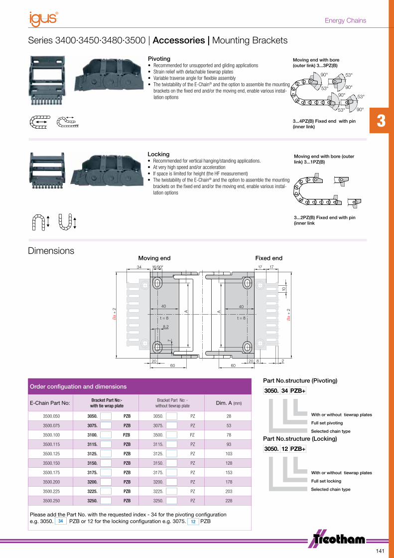
Order configuation and dimensions
E-Chain Part No: Bracket Part No:- with tie wrap plate
Bracket Part No: - without tiewrap plate Dim. A (mm)
3500.050 3050. PZB 3050. PZ 28
3500.075 3075. PZB 3075. PZ 53
3500.100 3100. PZB 3500. PZ 78
3500.115 3115. PZB 3115. PZ 93
3500.125 3125. PZB 3125. PZ 103
3500.150 3150. PZB 3150. PZ 128
3500.175 3175. PZB 3175. PZ 153
3500.200 3200. PZB 3200. PZ 178
3500.225 3225. PZB 3225. PZ 203
3500.250 3250. PZB 3250. PZ 228
Please add the Part No. with the requested index - 34 for the pivoting configuration e.g. 3050. 34 PZB or 12 for the locking configuration e.g. 3075. 12 PZB
DimensionsMoving end Fixed end
Moving end with bore (outer link) 3...1PZ(B)
53°
90°
53°
90° 53°
53°
90°
90°
3...2PZ(B) Fixed end with pin (inner link
Moving end with bore (outer link) 3...3PZ(B)
53°
90°
53°
90° 53°
53°
90°
90°
3...4PZ(B) Fixed end with pin (inner link)
Part No.structure (Locking)
Selected chain type
Full set locking
With or without tiewrap plates
3050. 12 PZB+
Part No.structure (Pivoting)
Selected chain type
Full set pivoting
With or without tiewrap plates
3050. 34 PZB+
Series 3400·3450·3480·3500 | Accessories | Mounting Brackets
Pivoting• Recommended for unsupported and gliding applications• Strain relief with detachable tiewrap plates• Variable traverse angle for flexible assembly• The twistability of the E-Chain® and the option to assemble the mounting
brackets on the fixed end and/or the moving end, enable various instal-lation options
Locking• Recommended for vertical hanging/standing applications.• At very high speed and/or acceleration• If space is limited for height (the HF measurement) • The twistability of the E-Chain® and the option to assemble the mounting
brackets on the fixed end and/or the moving end, enable various instal-lation options
3
141
Energy Chains

When to use the Series E4.56/H4.56/R4.56:• If a low-noise version is required• At very high speeds and/or
accelerations • For long travels • For high additional loads
When not to use it:• If the stability of a “light” version with
thinner side parts is required due to cost - and space reasons use Series 14240, page 130
Low noise version
available with special
rubber pads design
Opening E-Chains®: Remove cross-bars and clips - Insert screwdriver into the slot, push down, release by lever action
E4.1 | Series E4.56 | Extra Heavy DutyStraight run through inner-/outer-link designLow-noise operation through integrated brake in the radial stop dog systemBy the undercut design, very high stiffe ning and carrying capacity when shear forces are at work15% more tensile strength (compared to the best old E4 series), better unsupported length through improved stop dog system and vertical radial stopsCrossbar available for faster assembly/disassembly - 450.X.QShelving program with a wide range of options - interior separation for a quicker
cable insertion available - T563Version NC “without pretension” simply by turning outer links without rework possible
Crossbars are removable along both radiiHinged snap-open removable lids along outer radius of E-TubeWide, rounded plastic crossbars - cable friendly
Remove lids/bottoms (E-Tubes) - Insert screw driver into the slot, release by lever action
10
9
1
2
3
4
5
6
7
8
9
1
2
3
4
5
6
78
3
142
Energy Chains

Series E4.56 | Installation Dimensions and Technical Data
SD22/S2/S
R
K2
HRI
H2Moving End Fixed End
Guide trough with glide bar Guide trough without glide barTotal length of guide trough
R 135 150 175 200 240 250 300 350 400 450 500
H-0+25 354 384 434 484 564 584 684 784 884 984 1084
D 268 283 308 333 373 383 433 483 533 583 633
K 610 655 735 815 940 970 1125 1285 1440 1600 1755
D2+25 – 450 580 710 900 980 1180 1440 1530 1700 1850
K2 – 819 1092 1274 1547 1638 2002 2275 2548 2912 3276
H2 – 266 266 266 266 266 266 266 266 266 266
Pitch = 91 mm/link Links/m = 11 (1001 mm) Chain length = S/2 + K
Long travel lengths from 10 m to max. 400 m Chain length = S/2 + K2
Gliding, long travel applications (max. 400m) In this case the E-Chain® upper run will be introduced in a guide trough on the lower run. We recommend for long travel applications to contact Treotham Automation.
In case of travels between 4 and 10m we recommend a longer unsupported length.
Speed / acceleration FLG max. 20 [m/s] / max. 200 [m/s2]
Speed / acceleration FLB max. 3 [m/s] / max. 6 [m/s2]
Gliding speed / acceleration (maximum) max. 10 [m/s] / max. 50 [m/s2]
Material - permitted temperature °C igumid G / -40° up to +120° C
Flammability class, igumid G VDE 0304 IIC UL94 HB
0 2.0 4.0 6.0 8.0 10 12
0
0.5
1.0
1.5
2.04.08.01020
30
40
50
85
6065
75
0 0.5 1.0 2.0 3.0 4.0 5.0 6.01.5 2.5 3.5 4.5 5.5
FLB
FLG
Fill
wei
ght [
kg/m
]
Unsupported Length FLG /FLB (m)
D
H
H -
108R
S/2
S
108
111H
F =
H +
60Moving end
Fixed end
Unsupported lengthFLG = with straight upper runFLB = with permitted sag
S = Length of travelR = Bending radiusH = Nominal clearence heightHF = Required clearence heightHRI = Trough inner heightD = Overlength E-Chain®
radius in final positionK = π • R + “safety”D2 = Over length - long travels, glidingK2 = *Further add-onH2 = *Mounting height*if the mounting bracket location is set lower
Other installation methodsVertical, hanging ≤ 100 mVertical, standing ≤ 6 mSide mounted, unsupp. ≤ 2.5 m
Short travels - unsupportedUnsupported E-Chains® feature positive camber over short tra vels. This must be accounted for when specifying the clearance height HF.
3
143
Energy Chains

Series E4.56 - E-Chain® with crossbars every linkFor complete details of R4.56 & H4.56, please contact your nearest Treotham Automation office.**Available sizes of R4.56 E-Tubes
E-Chain Part No Bi[mm] Ba[mm] E-Chain Part No Bi[mm] Ba[mm] E-Chain Part No Bi[mm] Ba[mm]
E4.56.05. .0 50 84 E4.56.22. .0 225 259 **E4.56.40. .0 400 434
E4.56.06. .0 65 99 E4.56.23. .0 237 272 E4.56.41. .0 412 447
**E4.56.07. .0 75 109 **E4.56.25. .0 250 284 E4.56.42. .0 425 459
**E4.56.08. .0 87 121 E4.56.26. .0 262 297 E4.56.43. .0 437 472
**E4.56.10. .0 100 134 **E4.56.27. .0 275 309 E4.56.45. .0 450 484
E4.56.11. .0 112 147 E4.56.28. .0 287 322 **E4.56.46. .0 462 497
**E4.56.12. .0 125 159 **E4.56.30. .0 300 334 E4.56.47. .0 475 509
E4.56.13. .0 137 172 E4.56.31. .0 312 347 E4.56.48. .0 487 522
**E4.56.15. .0 150 184 E4.56.32. .0 325 359 E4.56.50. .0 500 534
E4.56.16. .0 162 197 E4.56.33. .0 337 372 E4.56.51. .0 512 547
E4.56.17 .0 175 209 **E4.56.35. .0 350 384 E4.56.52. .0 525 559
E4.56.18. .0 187 222 E4.56.36. .0 362 397 E4.56.53. .0 537 572
**E4.56.20. .0 200 234 E4.56.37. .0 375 409 E4.56.55. .0 550 584
E4.56.21. .0 212 247 E4.56.38. .0 387 422 E4.56.60. .0 600 634
Available bending radii
R [mm] 135** 150 175 200 240 250 300 350 400 450 500 Supplement Part No. with required radius. Example: E4.56.12 300 .0
BaBi
56 8450max.
BaBi
56 8450max.
Series E4.56 - E-Chain® with crossbars every link
• Crossbars every link• For rigid hydraulic hoses• For applications particularly demanding• Can be opened from two sides
• Crossbars every 2nd link = Standard• For nearly every situation• Can be opened from two sides
• Easy assembly• Stable• Attractive price
• Fully enclosed• Excellent cable protection against dirt• Protection against hot chips• Lids along the entire inner radius are completely removable.
• Lids along the entire outer radius are single sided snap-open with a hinge on the other side to keep them attached to the chain or completely removable.
Series R4.56 - Fully enclosed E-Tube
Series H4.56 - E-Chain® with crossbars every 2nd link
Part No. structureE4.56. 13. 250. 0
Colour Black
Bending Radius
Width
Series
3
144
Energy Chains
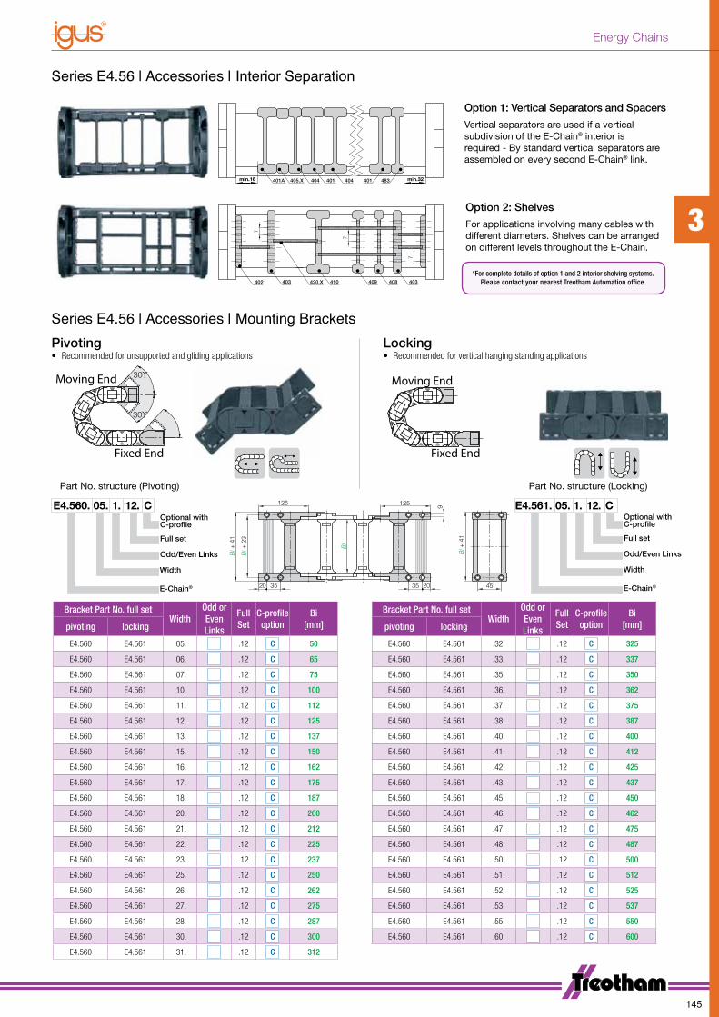
Optional with C-profile
Width
E-Chain®
Odd/Even Links
Full set
Bracket Part No. full setWidth
Odd or Even Links
Full Set
C-profileoption
Bi[mm]
Bracket Part No. full setWidth
Odd or Even Links
Full Set
C-profileoption
Bi[mm]pivoting locking pivoting locking
E4.560 E4.561 .05. .12 C 50 E4.560 E4.561 .32. .12 C 325
E4.560 E4.561 .06. .12 C 65 E4.560 E4.561 .33. .12 C 337
E4.560 E4.561 .07. .12 C 75 E4.560 E4.561 .35. .12 C 350
E4.560 E4.561 .10. .12 C 100 E4.560 E4.561 .36. .12 C 362
E4.560 E4.561 .11. .12 C 112 E4.560 E4.561 .37. .12 C 375
E4.560 E4.561 .12. .12 C 125 E4.560 E4.561 .38. .12 C 387
E4.560 E4.561 .13. .12 C 137 E4.560 E4.561 .40. .12 C 400
E4.560 E4.561 .15. .12 C 150 E4.560 E4.561 .41. .12 C 412
E4.560 E4.561 .16. .12 C 162 E4.560 E4.561 .42. .12 C 425
E4.560 E4.561 .17. .12 C 175 E4.560 E4.561 .43. .12 C 437
E4.560 E4.561 .18. .12 C 187 E4.560 E4.561 .45. .12 C 450
E4.560 E4.561 .20. .12 C 200 E4.560 E4.561 .46. .12 C 462
E4.560 E4.561 .21. .12 C 212 E4.560 E4.561 .47. .12 C 475
E4.560 E4.561 .22. .12 C 225 E4.560 E4.561 .48. .12 C 487
E4.560 E4.561 .23. .12 C 237 E4.560 E4.561 .50. .12 C 500
E4.560 E4.561 .25. .12 C 250 E4.560 E4.561 .51. .12 C 512
E4.560 E4.561 .26. .12 C 262 E4.560 E4.561 .52. .12 C 525
E4.560 E4.561 .27. .12 C 275 E4.560 E4.561 .53. .12 C 537
E4.560 E4.561 .28. .12 C 287 E4.560 E4.561 .55. .12 C 550
E4.560 E4.561 .30. .12 C 300 E4.560 E4.561 .60. .12 C 600
E4.560 E4.561 .31. .12 C 312
*For complete details of option 1 and 2 interior shelving systems.Please contact your nearest Treotham Automation office.
405.X401A 404 401404
402 420.X 408403
7
483401
409410
min.32min.16
7
403
7
405.X401A 404 401404
402 420.X 408403
7
483401
409410
min.32min.16
7
403
7
Series E4.56 | Accessories | Interior Separation
Series E4.56 | Accessories | Mounting Brackets
Option 1: Vertical Separators and Spacers
Vertical separators are used if a vertical subdivision of the E-Chain® interior is required - By standard vertical se parators are assembled on every second E-Chain® link.
Option 2: Shelves
For applications involving many cables with different dia meters. Shelves can be arranged on different levels throughout the E-Chain.
Pivoting• Recommended for unsupported and gliding applications
Locking• Recommended for vertical hanging standing applications
30ϒ
30ϒMoving End
Moving End
Fixed End
Fixed End
30ϒ
30ϒMoving End
Moving End
Fixed End
Fixed End
125 125
3520
Bi +
41
Bi +
23
Bi
2035
Bi +
41
45
9 E4.561. 05. 1. 12. COptional with C-profile
Width
E-Chain®
Odd/Even Links
Full set
E4.560. 05. 1. 12. C
Part No. structure (Pivoting) Part No. structure (Locking)
3
145
Energy Chains
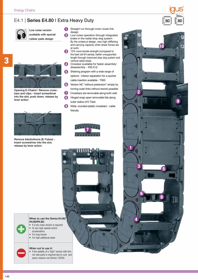
When to use the Series E4.80/H4.80/R4.80: • If a low-noise version is required• At very high speeds and/or
accelerations • For long travels • For high additional loads
When not to use it:• If the stability of a “light” version with thin-
ner side parts is required due to cost- and space reasons use (Series 15050)
Low noise version
available with special
rubber pads design
Opening E-Chains®: Remove cross-bars and clips - Insert screwdriver into the slot, push down, release by lever action
E4.1 | Series E4.80 | Extra Heavy Duty• Straight run through inner-/outer-link
design• Low-noise operation through integrated
brake in the radial stop dog system By the undercut design, very high stiffe ning and carrying capacity when shear forces are at work
• 15% more tensile strength (compared to the best old E4 series), better unsupported length through improved stop dog system and vertical radial stops
• Crossbar available for faster assembly/disassembly - 450.X.Q
• Shelving program with a wide range of
options - interior separation for a quicker
cable insertion available - T563
• Version NC “without pretension” simply by
turning outer links without rework possible
• Crossbars are removable along both radii
• Hinged snap-open removable lids along
outer radius of E-Tube
• Wide, rounded plastic crossbars - cable
friendly
Remove lids/bottoms (E-Tubes) -Insert screw driver into the slot,release by lever action
10
99
1
1
2
2
3
3
4
4
5
5
6
6
7
7
8
8
3
146
Energy Chains
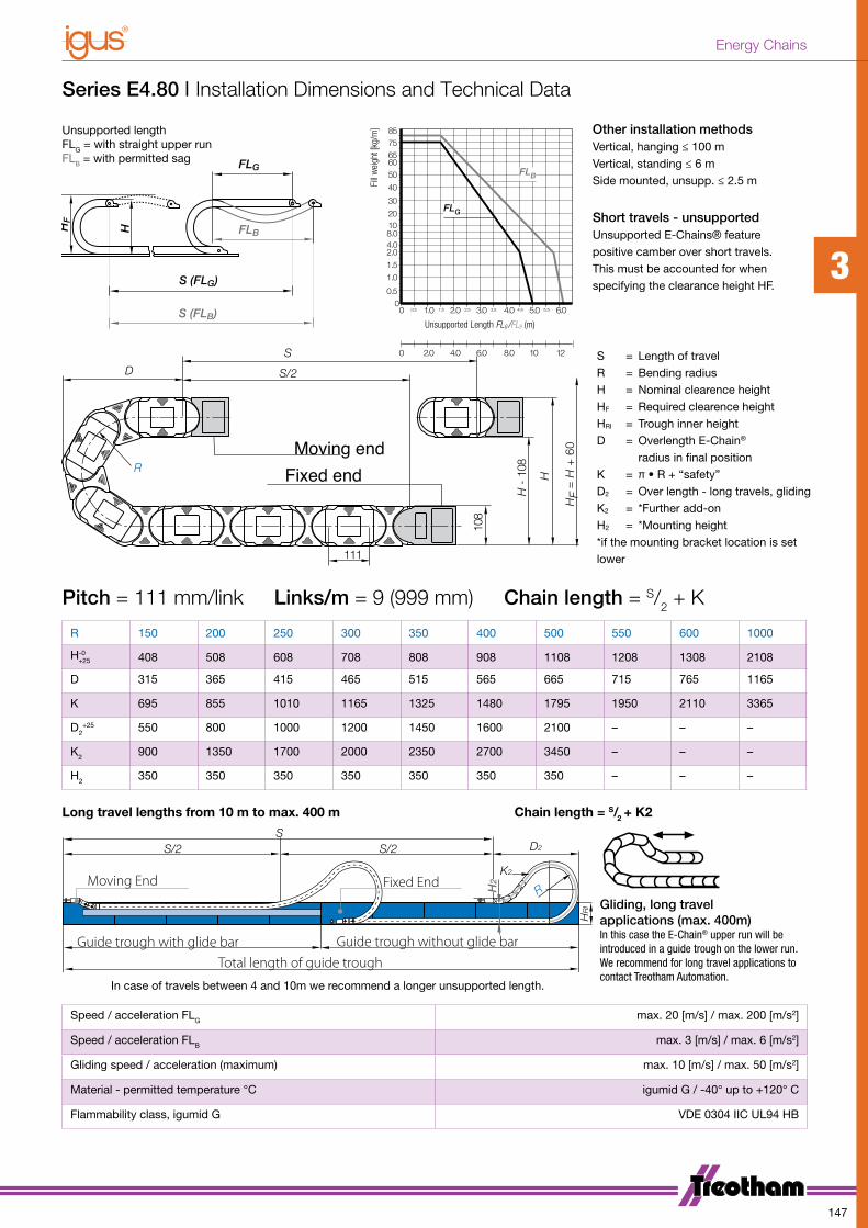
Series E4.80 | Installation Dimensions and Technical Data
SD22/S2/S
R
K2
HRI
H2Moving End Fixed End
Guide trough with glide bar Guide trough without glide barTotal length of guide trough
R 150 200 250 300 350 400 500 550 600 1000
H-0+25 408 508 608 708 808 908 1108 1208 1308 2108
D 315 365 415 465 515 565 665 715 765 1165
K 695 855 1010 1165 1325 1480 1795 1950 2110 3365
D2+25 550 800 1000 1200 1450 1600 2100 – – –
K2 900 1350 1700 2000 2350 2700 3450 – – –
H2 350 350 350 350 350 350 350 – – –
Pitch = 111 mm/link Links/m = 9 (999 mm) Chain length = S/2 + K
Long travel lengths from 10 m to max. 400 m Chain length = S/2 + K2
Gliding, long travel applications (max. 400m) In this case the E-Chain® upper run will be introduced in a guide trough on the lower run. We recommend for long travel applications to contact Treotham Automation.
In case of travels between 4 and 10m we recommend a longer unsupported length.
Speed / acceleration FLG max. 20 [m/s] / max. 200 [m/s2]
Speed / acceleration FLB max. 3 [m/s] / max. 6 [m/s2]
Gliding speed / acceleration (maximum) max. 10 [m/s] / max. 50 [m/s2]
Material - permitted temperature °C igumid G / -40° up to +120° C
Flammability class, igumid G VDE 0304 IIC UL94 HB
0 2.0 4.0 6.0 8.0 10 12
0
0.5
1.0
1.5
2.04.08.01020
30
40
50
85
6065
75
0 0.5 1.0 2.0 3.0 4.0 5.0 6.01.5 2.5 3.5 4.5 5.5
FLB
FLG
Fill
wei
ght [
kg/m
]
Unsupported Length FLG /FLB (m)
D
H
H -
108R
S/2
S
108
111H
F =
H +
60Moving end
Fixed end
Unsupported lengthFLG = with straight upper runFLB = with permitted sag
S = Length of travelR = Bending radiusH = Nominal clearence heightHF = Required clearence heightHRI = Trough inner heightD = Overlength E-Chain®
radius in final positionK = π • R + “safety”D2 = Over length - long travels, glidingK2 = *Further add-onH2 = *Mounting height*if the mounting bracket location is set lower
Other installation methodsVertical, hanging ≤ 100 mVertical, standing ≤ 6 mSide mounted, unsupp. ≤ 2.5 m
Short travels - unsupportedUnsupported E-Chains® feature positive camber over short tra vels. This must be accounted for when specifying the clearance height HF.
3
147
Energy Chains
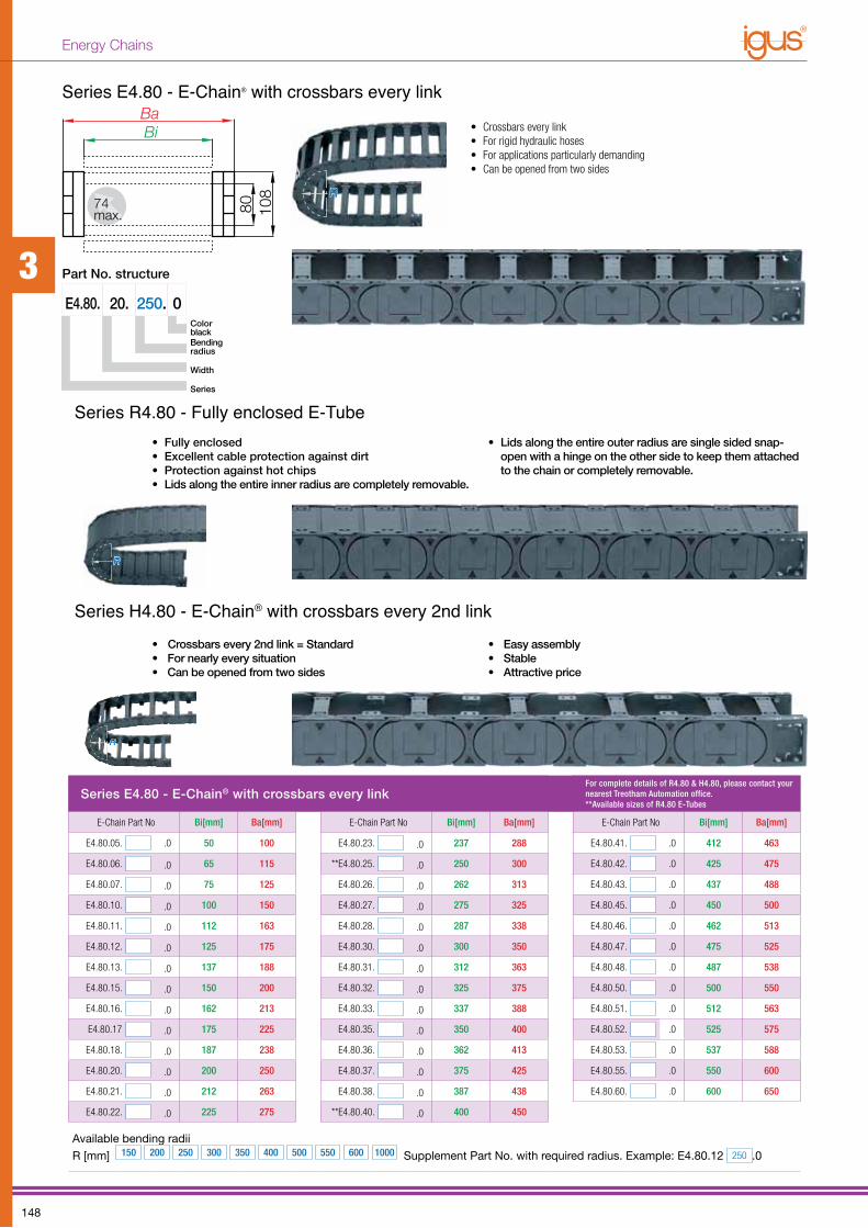
Series E4.80 - E-Chain® with crossbars every linkFor complete details of R4.80 & H4.80, please contact your nearest Treotham Automation office.**Available sizes of R4.80 E-Tubes
E-Chain Part No Bi[mm] Ba[mm] E-Chain Part No Bi[mm] Ba[mm] E-Chain Part No Bi[mm] Ba[mm]
E4.80.05. .0 50 100 E4.80.23. .0 237 288 E4.80.41. .0 412 463
E4.80.06. .0 65 115 **E4.80.25. .0 250 300 E4.80.42. .0 425 475
E4.80.07. .0 75 125 E4.80.26. .0 262 313 E4.80.43. .0 437 488
E4.80.10. .0 100 150 E4.80.27. .0 275 325 E4.80.45. .0 450 500
E4.80.11. .0 112 163 E4.80.28. .0 287 338 E4.80.46. .0 462 513
E4.80.12. .0 125 175 E4.80.30. .0 300 350 E4.80.47. .0 475 525
E4.80.13. .0 137 188 E4.80.31. .0 312 363 E4.80.48. .0 487 538
E4.80.15. .0 150 200 E4.80.32. .0 325 375 E4.80.50. .0 500 550
E4.80.16. .0 162 213 E4.80.33. .0 337 388 E4.80.51. .0 512 563
E4.80.17 .0 175 225 E4.80.35. .0 350 400 E4.80.52. .0 525 575
E4.80.18. .0 187 238 E4.80.36. .0 362 413 E4.80.53. .0 537 588
E4.80.20. .0 200 250 E4.80.37. .0 375 425 E4.80.55. .0 550 600
E4.80.21. .0 212 263 E4.80.38. .0 387 438 E4.80.60. .0 600 650
E4.80.22. .0 225 275 **E4.80.40. .0 400 450
Available bending radii
R [mm] 150 200 250 300 350 400 500 550 600 1000 Supplement Part No. with required radius. Example: E4.80.12 250 .0
BaBi
80 108
74max.
BaBi
80 108
74max.
E4.80. 20. 0250.
Part No. structure
Color
black Bending radius
Width
Series
Series E4.80 - E-Chain® with crossbars every link
• Crossbars every link• For rigid hydraulic hoses• For applications particularly demanding• Can be opened from two sides
• Crossbars every 2nd link = Standard• For nearly every situation• Can be opened from two sides
• Easy assembly• Stable• Attractive price
• Fully enclosed• Excellent cable protection against dirt• Protection against hot chips• Lids along the entire inner radius are completely removable.
• Lids along the entire outer radius are single sided snap-open with a hinge on the other side to keep them attached to the chain or completely removable.
Series R4.80 - Fully enclosed E-Tube
Series H4.80 - E-Chain® with crossbars every 2nd link
3
148
Energy Chains
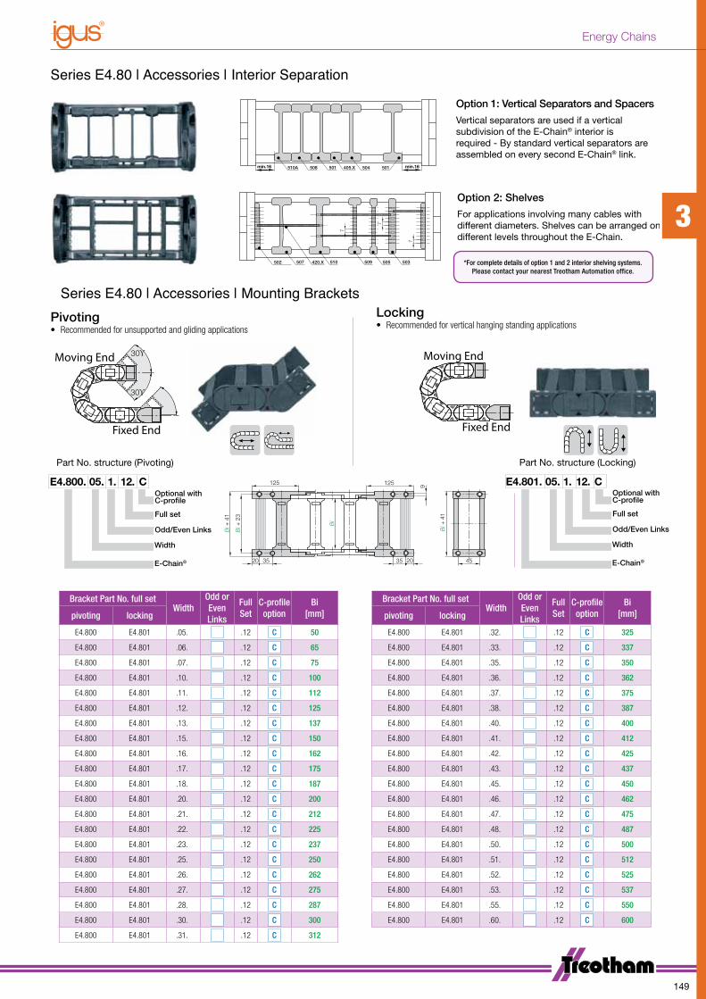
Optional with C-profile
Width
E-Chain®
Odd/Even Links
Full set
405.X510A 504 501508
502 420.X 505507
501
509510
7
503
min.16min.16
7
7
405.X510A 504 501508
502 420.X 505507
501
509510
7
503
min.16min.16
7
7
Series E4.80 | Accessories | Interior Separation
Series E4.80 | Accessories | Mounting Brackets
Option 1: Vertical Separators and Spacers
Vertical separators are used if a vertical subdivision of the E-Chain® interior is required - By standard vertical se parators are assembled on every second E-Chain® link.
Option 2: Shelves
For applications involving many cables with different dia meters. Shelves can be arranged on different levels throughout the E-Chain.
Pivoting• Recommended for unsupported and gliding applications
Locking• Recommended for vertical hanging standing applications
30ϒ
30ϒMoving End
Moving End
Fixed End
Fixed End
30ϒ
30ϒMoving End
Moving End
Fixed End
Fixed End
125 125
3520
Bi +
41
Bi +
23
Bi
2035
Bi +
41
45
9 E4.801. 05. 1. 12. COptional with C-profile
Width
E-Chain®
Odd/Even Links
Full set
E4.800. 05. 1. 12. C
Part No. structure (Pivoting) Part No. structure (Locking)
Bracket Part No. full setWidth
Odd or Even Links
Full Set
C-profileoption
Bi[mm]
Bracket Part No. full setWidth
Odd or Even Links
Full Set
C-profileoption
Bi[mm]pivoting locking pivoting locking
E4.800 E4.801 .05. .12 C 50 E4.800 E4.801 .32. .12 C 325
E4.800 E4.801 .06. .12 C 65 E4.800 E4.801 .33. .12 C 337
E4.800 E4.801 .07. .12 C 75 E4.800 E4.801 .35. .12 C 350
E4.800 E4.801 .10. .12 C 100 E4.800 E4.801 .36. .12 C 362
E4.800 E4.801 .11. .12 C 112 E4.800 E4.801 .37. .12 C 375
E4.800 E4.801 .12. .12 C 125 E4.800 E4.801 .38. .12 C 387
E4.800 E4.801 .13. .12 C 137 E4.800 E4.801 .40. .12 C 400
E4.800 E4.801 .15. .12 C 150 E4.800 E4.801 .41. .12 C 412
E4.800 E4.801 .16. .12 C 162 E4.800 E4.801 .42. .12 C 425
E4.800 E4.801 .17. .12 C 175 E4.800 E4.801 .43. .12 C 437
E4.800 E4.801 .18. .12 C 187 E4.800 E4.801 .45. .12 C 450
E4.800 E4.801 .20. .12 C 200 E4.800 E4.801 .46. .12 C 462
E4.800 E4.801 .21. .12 C 212 E4.800 E4.801 .47. .12 C 475
E4.800 E4.801 .22. .12 C 225 E4.800 E4.801 .48. .12 C 487
E4.800 E4.801 .23. .12 C 237 E4.800 E4.801 .50. .12 C 500
E4.800 E4.801 .25. .12 C 250 E4.800 E4.801 .51. .12 C 512
E4.800 E4.801 .26. .12 C 262 E4.800 E4.801 .52. .12 C 525
E4.800 E4.801 .27. .12 C 275 E4.800 E4.801 .53. .12 C 537
E4.800 E4.801 .28. .12 C 287 E4.800 E4.801 .55. .12 C 550
E4.800 E4.801 .30. .12 C 300 E4.800 E4.801 .60. .12 C 600
E4.800 E4.801 .31. .12 C 312
*For complete details of option 1 and 2 interior shelving systems.Please contact your nearest Treotham Automation office.
3
149
Energy Chains
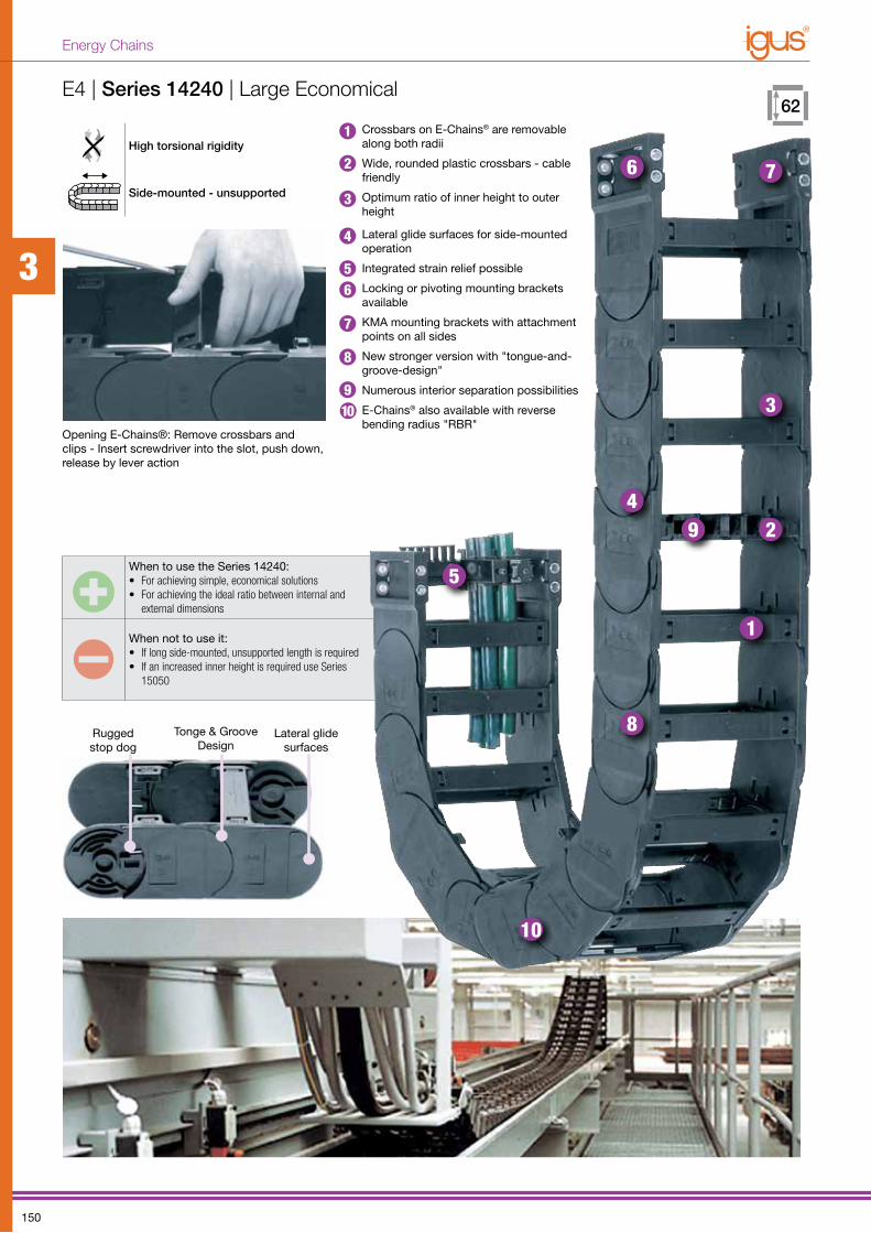
High torsional rigidity
Side-mounted - unsupported
When to use the Series 14240:• For achieving simple, economical solutions• For achieving the ideal ratio between internal and
external dimensions
When not to use it:• If long side-mounted, unsupported length is required • If an increased inner height is required use Series
15050
Opening E-Chains®: Remove crossbars and clips - Insert screwdriver into the slot, push down, release by lever action
E4 | Series 14240 | Large Economical
1
2
3
4
5
6 7
8
9
10
Rugged stop dog
Tonge & Groove Design
Lateral glide surfaces
Crossbars on E-Chains® are removable along both radii
Wide, rounded plastic crossbars - cable friendly
Optimum ratio of inner height to outer height
Lateral glide surfaces for side-mounted operation
Integrated strain relief possible
Locking or pivoting mounting brackets available
KMA mounting brackets with attachment points on all sides
New stronger version with "tongue-and-groove-design"
Numerous interior separation possibilities
E-Chains® also available with reverse bending radius "RBR"
109
1
2
3
4
56
7
8
3
150
Energy Chains
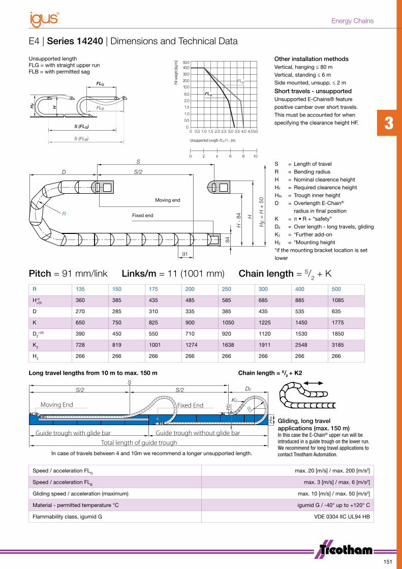
0.5
1.5
0
1.0
0
2.0
6.0
0.5 1.0 2.01.5 2.5 3.0 3.5 4.0 5.04.5
10.0
20.0
40.050.0
30.0
0 2 4 86 10
FLG
FLBFill
wei
ght [
kg/m
]
Unsupported Length FLG /FLB (m)
FLG
FLB
H
HF
S (FLG)
S (FLB)
D S/2
S
H
H -
84
HF = H +
50
91
R
84
Moving end
Fixed end
SD22/S2/S
R
K2
HRI
H2Moving End Fixed End
Guide trough with glide bar Guide trough without glide barTotal length of guide trough
E4 | Series 14240 | Dimensions and Technical Data
R 135 150 175 200 250 300 400 500
H-0+25 360 385 435 485 585 685 885 1085
D 270 285 310 335 385 435 535 635
K 650 750 825 900 1050 1225 1450 1775
D2+25 390 450 550 710 920 1120 1530 1850
K2 728 819 1001 1274 1638 1911 2548 3185
H2 266 266 266 266 266 266 266 266
Unsupported lengthFLG = with straight upper runFLB = with permitted sag
Pitch = 91 mm/link Links/m = 11 (1001 mm) Chain length = S/2 + K
Long travel lengths from 10 m to max. 150 m Chain length = S/2 + K2
Gliding, long travel applications (max. 150 m) In this case the E-Chain® upper run will be introduced in a guide trough on the lower run. We recommend for long travel applications to contact Treotham Automation. In case of travels between 4 and 10m we recommend a longer unsupported length.
Speed / acceleration FLG max. 20 [m/s] / max. 200 [m/s2]
Speed / acceleration FLB max. 3 [m/s] / max. 6 [m/s2]
Gliding speed / acceleration (maximum) max. 10 [m/s] / max. 50 [m/s2]
Material - permitted temperature °C igumid G / -40° up to +120° C
Flammability class, igumid G VDE 0304 IIC UL94 HB
S = Length of travelR = Bending radiusH = Nominal clearence heightHF = Required clearence heightHRI = Trough inner heightD = Overlength E-Chain®
radius in final positionK = π • R + “safety”D2 = Over length - long travels, glidingK2 = *Further add-onH2 = *Mounting height*if the mounting bracket location is set lower
Other installation methodsVertical, hanging ≤ 80 mVertical, standing ≤ 6 mSide mounted, unsupp. ≤ 2 m
Short travels - unsupportedUnsupported E-Chains® feature positive camber over short tra vels. This must be accounted for when specifying the clearance height HF. 3
151
Energy Chains
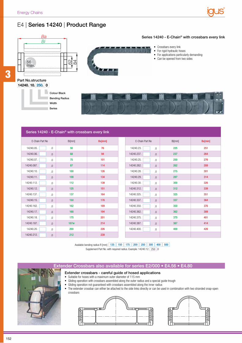
Colour Black
Series
Width
Bending Radius
14240. 10. 250. 0Part No.structure
Series 14240 - E-Chain® with crossbars every link
E-Chain Part No Bi[mm] Ba[mm] E-Chain Part No Bi[mm] Ba[mm]
14240.05. .0 50 76 14240.23. .0 225 251
14240.06. .0 68 94 14240.237. .0 237 264
14240.07. .0 75 101 14240.25. .0 250 276
14240.087. .0 87 114 14240.262. .0 262 289
14240.10. .0 100 126 14240.28. .0 275 301
14240.11. .0 108 134 14240.29. .0 287 314
14240.112. .0 112 139 14240.30. .0 300 326
14240.12. .0 125 151 14240.312. .0 312 339
14240.137. .0 137 164 14240.325. .0 325 351
14240.15. .0 150 176 14240.337. .0 337 364
14240.162. .0 162 189 14240.350. .0 350 376
14240.17. .0 168 194 14240.362. .0 362 389
14240.18. .0 175 201 14240.375. .0 375 401
14240.187. .0 187w 214 14240.387. .0 387 414
14240.20. .0 200 226 14240.400. .0 400 426
14240.212. .0 212 239
Available bending radius R [mm] 135 150 175 200 250 300 400 500
Supplement Part No. with required radius. Example: 14240.12. 250 .0
Extender crossbars - careful guide of hosed applications• Suitable for hoses with a maximum outer diameter of 115 mm• Gliding operation with crossbars assembled along the outer radius and a special guide trough• Gliding operation not guaranteed with crossbars assembled along the inner radius• The extender crossbar can either be attached to the side links directly or can be used in combination with two stranded snap-open
crossbars
Extender Crossbars also available for series E2/000 • E4.56 • E4.80
Series 14240 - E-Chain® with crossbars every link
E4 | Series 14240 | Product Range
• Crossbars every link• For rigid hydraulic hoses• For applications particularly demanding• Can be opened from two sides
Ba
Bi
62
8456
max.
3
152
Energy Chains
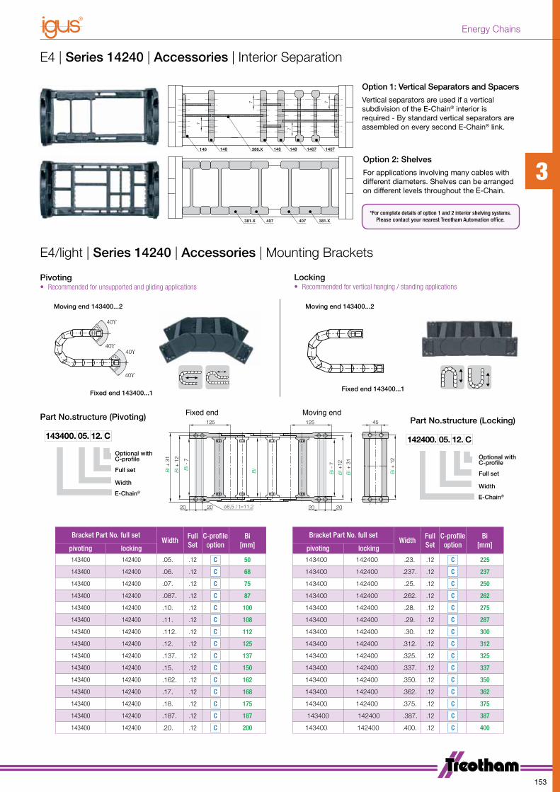
381.X 407
X.863641 1407148
7
381.X407
148 1407148
7
7
7
Option 1: Vertical Separators and Spacers
Vertical separators are used if a vertical subdivision of the E-Chain® interior is required - By standard vertical se parators are assembled on every second E-Chain® link.
381.X 407
X.863641 1407148
7
381.X407
148 1407148
7
7
7
Option 2: Shelves
For applications involving many cables with different dia meters. Shelves can be arranged on different levels throughout the E-Chain.
125
20
Bi +
31
Bi +
12
Bi
Bi +
12
Bi +
31
Bi -
7
Bi -
7
125
2020 20
Bi +
12
45
ø8,5 / t=11,2
Fixed end Moving end
Pivoting• Recommended for unsupported and gliding applications
Locking• Recommended for vertical hanging / standing applications
Optional with C-profile
E-Chain®
Width
Full set
143400. 05. 12. C
Part No.structure (Pivoting) Part No.structure (Locking)
Optional with C-profile
E-Chain®
Width
Full set
142400. 05. 12. C
Moving end 143400...2
40ϒ
40ϒ40ϒ
40ϒ
Fixed end 143400...1
Moving end 143400...240ϒ
40ϒ40ϒ
40ϒ
Fixed end 143400...1
*For complete details of option 1 and 2 interior shelving systems.Please contact your nearest Treotham Automation office.
Bracket Part No. full setWidth
Full Set
C-profileoption
Bi[mm]
Bracket Part No. full setWidth
Full Set
C-profileoption
Bi[mm]pivoting locking pivoting locking
143400 142400 .05. .12 C 50 143400 142400 .23. .12 C 225
143400 142400 .06. .12 C 68 143400 142400 .237. .12 C 237
143400 142400 .07. .12 C 75 143400 142400 .25. .12 C 250
143400 142400 .087. .12 C 87 143400 142400 .262. .12 C 262
143400 142400 .10. .12 C 100 143400 142400 .28. .12 C 275
143400 142400 .11. .12 C 108 143400 142400 .29. .12 C 287
143400 142400 .112. .12 C 112 143400 142400 .30. .12 C 300
143400 142400 .12. .12 C 125 143400 142400 .312. .12 C 312
143400 142400 .137. .12 C 137 143400 142400 .325. .12 C 325
143400 142400 .15. .12 C 150 143400 142400 .337. .12 C 337
143400 142400 .162. .12 C 162 143400 142400 .350. .12 C 350
143400 142400 .17. .12 C 168 143400 142400 .362. .12 C 362
143400 142400 .18. .12 C 175 143400 142400 .375. .12 C 375
143400 142400 .187. .12 C 187 143400 142400 .387. .12 C 387
143400 142400 .20. .12 C 200 143400 142400 .400. .12 C 400
E4 | Series 14240 | Accessories | Interior Separation
E4/light | Series 14240 | Accessories | Mounting Brackets
3
153
Energy Chains

Guide Troughs | Long travels with Guide Troughs
HeavyDuty
Basic
Steel guide troughs
• Very simple, modular assembly• Side-mounted glide strips for wear protection in high-speed• Corrosion resistant, seawater resistant aluminiu profile• Flexible assembly - Fastening on substructure independent
of profile lengths and butt joints• Interface connector - Plastic with snap-in connection• Plastic glide bar made of PE• Bottom clamp can be mounted -inside or outside- directly on the
bottom or on the c-profile• Glide strips and silencer profile for the minimization of the noise
level• Heavy duty brackets for safe connection also for rough
applications• C-profile for the fixation of the bottom clamp or heavy duty
bracketst
Aluminium “SuperTrough” - The igus® standard guide trough
• Easy assembly with installation set• Big range, two piece design, adjustable to EChain® width• Available in galvanized steel and stainless steel• Glide bar made of PE
Steel guide trough - very stable and rugged for heavy duty applications
Basic-Version:Fast assembly
Heavy-Version:plant manufacturing
Steel Guide Trough System on a ship loader for coal un-loading, travel 105m, speed 240m/min, load 53kg/m
3
154
Energy Chains

Guide Troughs | Long travels with Guide Troughs
Trough without glide bars - E-Chain® glides on E-Chain®
Trough with glide bars - E-Chain® glides on glide bars
Center mounted: 1/2 Travel with glide bars - 1/2 Travel without glide bars
igus® guide troughs
Guide troughs are used for long travels, (travels from 5 to 12 m) and greater, depending on the E-Chain® type. They allow to continue smooth, low-friction operation in these long-travel situations. If the E-Chains® are installed in the center of the travel (“center-mounted”), they glide on themselves for half the travel. For the other half, we recommend glide bars, which are assembled in the trough and on which the E-Chains® glide. igus® guide troughs are available from stock with these highly abrasion-resistant polymer glide bars, which perform well with igus® E-Chains® regarding noise, abrasion and friction.
Trough typeigus® offers guide troughs made of corrosion-resistant aluminum, steel, stainless steel, as well as tubes and insert troughs (with steel side plates). The trough type to be used depends on the application conditions and the requirements of the customer. We recommend the igus® standard super aluminum guide troughs.
Glide barsGlide bars made of igulen are optimally matched to the E-Chain® material and achieve the lowest values for friction, noise and wear. Glide bars must be used, if the fixed point is in the center of the travel. It means: Use half of the guide trough with glide bars and the other half of the guide trough without glide bars.
Delivery conditionThe troughs are delivered in 2 meter sections. Special lengths up to 6 m are possible. The left and right side parts are installed on location with the appropriate distance - depend-ing on the width of the E-Chain®. The necessary width is shown by the dimension BRI on the guide trough pages. The E-Chain® sides can be linked with the base through screwing, welding or a special igus® installation set. The fixation module for the igus® Super-Alu-Trough is a quick fix for mounting the stationary end of an E-Chain® with a KMA-mounting bracket. With this new module a fast and easy mounting onto the Super-Aluminum-Trough is possible without any drilling.
3
155
Energy Chains