Embed Size (px)
Citation preview
3100
6901
.00
Unity ProLL984Block Library11/2005

2 31006901 11/2005
Table of Contents
Safety Information . . . . . . . . . . . . . . . . . . . . . . . . . . . . . . . . . . . .9
About the Book . . . . . . . . . . . . . . . . . . . . . . . . . . . . . . . . . . . . . .11
Part I General information . . . . . . . . . . . . . . . . . . . . . . . . . . . . . 13
Chapter 1 Block types and their applications . . . . . . . . . . . . . . . . . . . . . .15Block types . . . . . . . . . . . . . . . . . . . . . . . . . . . . . . . . . . . . . . . . . . . . . . . . . . . . . 16FFB Structure . . . . . . . . . . . . . . . . . . . . . . . . . . . . . . . . . . . . . . . . . . . . . . . . . . . 17EN and ENO . . . . . . . . . . . . . . . . . . . . . . . . . . . . . . . . . . . . . . . . . . . . . . . . . . . . 20
Chapter 2 Availability of the blocks on different hardware platforms . .23
Part II Counters and Timers . . . . . . . . . . . . . . . . . . . . . . . . . . . . 25
Chapter 3 LL_DCTR: Down Counter. . . . . . . . . . . . . . . . . . . . . . . . . . . . . .27
Chapter 4 LL_T001: One Hundredth Second Timer . . . . . . . . . . . . . . . . .31
Chapter 5 LL_T01: One Tenth Second Timer . . . . . . . . . . . . . . . . . . . . . .35
Chapter 6 LL_T1: One Second Timer . . . . . . . . . . . . . . . . . . . . . . . . . . . . .39
Chapter 7 LL_T1MS: One Millisecond Timer . . . . . . . . . . . . . . . . . . . . . . .43
Chapter 8 LL_UCTR: Up Counter . . . . . . . . . . . . . . . . . . . . . . . . . . . . . . . .47
Part III Math . . . . . . . . . . . . . . . . . . . . . . . . . . . . . . . . . . . . . . . . . . 51
Chapter 9 LL_AD16: Add 16-bit . . . . . . . . . . . . . . . . . . . . . . . . . . . . . . . . .53
Chapter 10 LL_ADD: Addition. . . . . . . . . . . . . . . . . . . . . . . . . . . . . . . . . . . .57
Chapter 11 LL_DIV: Divide . . . . . . . . . . . . . . . . . . . . . . . . . . . . . . . . . . . . . .61
Chapter 12 LL_DV16: Divide 16-Bit . . . . . . . . . . . . . . . . . . . . . . . . . . . . . . .65
31006901 11/2005 3
Chapter 13 MU16: Multiply 16-Bit. . . . . . . . . . . . . . . . . . . . . . . . . . . . . . . . . 69
Chapter 14 MUL: Multiply . . . . . . . . . . . . . . . . . . . . . . . . . . . . . . . . . . . . . . . 73
Chapter 15 LL_SU16: Subtract 16-bit . . . . . . . . . . . . . . . . . . . . . . . . . . . . . 77
Chapter 16 LL_SUB: Subtraction. . . . . . . . . . . . . . . . . . . . . . . . . . . . . . . . . 81
Part IV Matrix . . . . . . . . . . . . . . . . . . . . . . . . . . . . . . . . . . . . . . . . .85
Chapter 17 LL_AND_00: Logical AND (%M -%M) . . . . . . . . . . . . . . . . . . . . 87
Chapter 18 LL_AND_04: Logical AND (%M - %MW). . . . . . . . . . . . . . . . . . 91
Chapter 19 LL_AND_10: Logical AND (%I - %M) . . . . . . . . . . . . . . . . . . . . 95
Chapter 20 LL_AND_14: Logical AND (%I - %MW). . . . . . . . . . . . . . . . . . . 99
Chapter 21 LL_AND_30: Logical AND (%IW - %M). . . . . . . . . . . . . . . . . . 103
Chapter 22 LL_AND_34: Logical AND (%IW - %MW) . . . . . . . . . . . . . . . . 107
Chapter 23 LL_AND_40: Logical AND (%MW - %M). . . . . . . . . . . . . . . . . 111
Chapter 24 LL_AND_44: Logical AND (%MW - %MW) . . . . . . . . . . . . . . . 115
Chapter 25 LL_BROT_00: Bit Rotate (%M -%M) . . . . . . . . . . . . . . . . . . . . 119
Chapter 26 LL_BROT_04: Bit Rotate (%M - %MW). . . . . . . . . . . . . . . . . . 123
Chapter 27 LL_BROT_10: Bit Rotate (%I - %M) . . . . . . . . . . . . . . . . . . . . 127
Chapter 28 LL_BROT_14: Bit Rotate (%I - %MW). . . . . . . . . . . . . . . . . . . 131
Chapter 29 LL_BROT_30: Bit Rotate (%IW - %M). . . . . . . . . . . . . . . . . . . 135
Chapter 30 LL_BROT_34: Bit Rotate (%IW - %MW) . . . . . . . . . . . . . . . . . 139
Chapter 31 LL_BROT_40: Bit Rotate (%MW - %M). . . . . . . . . . . . . . . . . . 143
Chapter 32 LL_BROT_44: Bit Rotate (%MW - %MW) . . . . . . . . . . . . . . . . 147
Chapter 33 LL_MBIT_X0: Modify Bit (%M) . . . . . . . . . . . . . . . . . . . . . . . . 151
Chapter 34 LL_MBIT_X4: Modify Bit (%MW). . . . . . . . . . . . . . . . . . . . . . . 155
Chapter 35 LL_NBIT: Bit Control . . . . . . . . . . . . . . . . . . . . . . . . . . . . . . . . 159
Chapter 36 LL_NCBT: Normally Closed Bit . . . . . . . . . . . . . . . . . . . . . . . 161
Chapter 37 LL_NOBT: Normally Open Bit. . . . . . . . . . . . . . . . . . . . . . . . . 163
4 31006901 11/2005
Chapter 38 LL_OR_00: Logical OR (%M -%M). . . . . . . . . . . . . . . . . . . . . .165
Chapter 39 LL_OR_04: Logical OR (%M - %MW) . . . . . . . . . . . . . . . . . . .169
Chapter 40 LL_OR_10: Logical OR (%I - %M) . . . . . . . . . . . . . . . . . . . . . .173
Chapter 41 LL_OR_14: Logical OR (%I - %MW) . . . . . . . . . . . . . . . . . . . .177
Chapter 42 LL_OR_30: Logical OR (%IW - %M) . . . . . . . . . . . . . . . . . . . .181
Chapter 43 LL_OR_34: Logical OR (%IW - %MW) . . . . . . . . . . . . . . . . . . .185
Chapter 44 LL_OR_40: Logical OR (%MW - %M) . . . . . . . . . . . . . . . . . . .189
Chapter 45 LL_OR_44: Logical OR (%MW - %MW) . . . . . . . . . . . . . . . . . .193
Chapter 46 LL_RBIT: Reset Bit . . . . . . . . . . . . . . . . . . . . . . . . . . . . . . . . . .197
Chapter 47 LL_SBIT: Set Bit . . . . . . . . . . . . . . . . . . . . . . . . . . . . . . . . . . . .199
Chapter 48 LL_SENS_X0: Sense (%M). . . . . . . . . . . . . . . . . . . . . . . . . . . .201
Chapter 49 LL_SENS_X1: Sense (%I). . . . . . . . . . . . . . . . . . . . . . . . . . . . .205
Chapter 50 LL_SENS_X3: Sense (%IW) . . . . . . . . . . . . . . . . . . . . . . . . . . .209
Chapter 51 LL_SENS_X4: Sense (%MW) . . . . . . . . . . . . . . . . . . . . . . . . . .213
Chapter 52 LL_OR_00: Exclusive OR (%M -%M). . . . . . . . . . . . . . . . . . . .217
Chapter 53 LL_XOR_04: Exclusive OR (%M - %MW) . . . . . . . . . . . . . . . .221
Chapter 54 LL_XOR_10: Exclusive OR (%I - %M) . . . . . . . . . . . . . . . . . . .225
Chapter 55 LL_XOR_14: Exclusive OR (%I - %MW) . . . . . . . . . . . . . . . . .229
Chapter 56 LL_XOR_30: Exclusive OR (%IW - %M) . . . . . . . . . . . . . . . . .233
Chapter 57 LL_XOR_34: Exclusive OR (%IW - %MW). . . . . . . . . . . . . . . .237
Chapter 58 LL_XOR_40: Exclusive OR (%MW - %M) . . . . . . . . . . . . . . . .241
Chapter 59 LL_XOR_44: Exclusive OR (%MW - %MW). . . . . . . . . . . . . . .245
Part V Move . . . . . . . . . . . . . . . . . . . . . . . . . . . . . . . . . . . . . . . . 249
Chapter 60 LL_BLKM_00: Block Move (%M -%M). . . . . . . . . . . . . . . . . . .251
Chapter 61 LL_BLKM_04: Block Move (%M - %MW) . . . . . . . . . . . . . . . .255
Chapter 62 LL_BLKM_10: Block Move (%I - %M) . . . . . . . . . . . . . . . . . . .259
31006901 11/2005 5
Chapter 63 LL_BLKM_14: Block Move (%I - %MW) . . . . . . . . . . . . . . . . . 263
Chapter 64 LL_BLKM_30: Block Move (%IW - %M) . . . . . . . . . . . . . . . . . 267
Chapter 65 LL_BLKM_34: Block Move (%IW - %MW) . . . . . . . . . . . . . . . 271
Chapter 66 LL_BLKM_40: Block Move (%MW - %M) . . . . . . . . . . . . . . . . 275
Chapter 67 LL_BLKM_44: Block Move (%MW - %MW) . . . . . . . . . . . . . . 279
Chapter 68 LL_BLKT: Block to Table . . . . . . . . . . . . . . . . . . . . . . . . . . . . 283
Chapter 69 LL_FIN_04: First In (%M - %MW) . . . . . . . . . . . . . . . . . . . . . . 287
Chapter 70 LL_FIN_14: First In (%I - %MW) . . . . . . . . . . . . . . . . . . . . . . . 291
Chapter 71 LL_FIN_34: First In (%IW - %MW). . . . . . . . . . . . . . . . . . . . . . 295
Chapter 72 LL_FIN_44: First In (%MW - %MW). . . . . . . . . . . . . . . . . . . . . 299
Chapter 73 LL_FOUT_40: First Out (%MW - %M) . . . . . . . . . . . . . . . . . . . 303
Chapter 74 LL_FOUT_44: First Out (%MW - %MW) . . . . . . . . . . . . . . . . . 307
Chapter 75 LL_R_TO_T_04: Register to Table (%M - %MW) . . . . . . . . . . 311
Chapter 76 LL_R_TO_T_14: Register to Table (%I - %MW) . . . . . . . . . . . 315
Chapter 77 LL_R_TO_T_34: Register to Table (%IW - %MW) . . . . . . . . . 319
Chapter 78 LL_R_TO_T_44: Register to Table (%MW - %MW) . . . . . . . . 323
Chapter 79 LL_T_TO_R_04: Table to Register (%M - %MW) . . . . . . . . . . 327
Chapter 80 LL_T_TO_R_14: Table to Register (%I - %MW) . . . . . . . . . . . 331
Chapter 81 LL_T_TO_R_34: Table to Register (%IW - %MW) . . . . . . . . . 335
Chapter 82 LL_T_TO_R_44: Table to Register (%MW - %MW) . . . . . . . . 339
Chapter 83 LL_T_TO_T_04: Table to Table (%M - %MW) . . . . . . . . . . . . 343
Chapter 84 LL_T_TO_T_14: Table to Table (%I - %MW) . . . . . . . . . . . . . 347
Chapter 85 LL_T_TO_T_34: Table to Table (%IW - %MW) . . . . . . . . . . . . 351
Chapter 86 LL_T_TO_T_44: Table to Table (%MW - %MW) . . . . . . . . . . . 355
Chapter 87 LL_TBLK: Table to Block . . . . . . . . . . . . . . . . . . . . . . . . . . . . 359
6 31006901 11/2005
Appendices . . . . . . . . . . . . . . . . . . . . . . . . . . . . . . . . . . . . . . . . . . . . . 363
Appendix A EFB Error Codes and Values. . . . . . . . . . . . . . . . . . . . . . . . . .365
Appendix B System objects . . . . . . . . . . . . . . . . . . . . . . . . . . . . . . . . . . . . .367System bit introduction . . . . . . . . . . . . . . . . . . . . . . . . . . . . . . . . . . . . . . . . . . . 368Description of System Bits %S9 to %S13 . . . . . . . . . . . . . . . . . . . . . . . . . . . . . 369Description of system bits %S15 to %S21 . . . . . . . . . . . . . . . . . . . . . . . . . . . . 370Description of System Words %SW12 to %SW19 . . . . . . . . . . . . . . . . . . . . . . 372
Glossary . . . . . . . . . . . . . . . . . . . . . . . . . . . . . . . . . . . . . . . . . . . . . 375
Index . . . . . . . . . . . . . . . . . . . . . . . . . . . . . . . . . . . . . . . . . . . . . 393
31006901 11/2005 7

8 31006901 11/2005

§
Safety InformationImportant Information
NOTICE Read these instructions carefully, and look at the equipment to become familiar with the device before trying to install, operate, or maintain it. The following special messages may appear throughout this documentation or on the equipment to warn of potential hazards or to call attention to information that clarifies or simplifies a procedure.
The addition of this symbol to a Danger or Warning safety label indicatesthat an electrical hazard exists, which will result in personal injury if theinstructions are not followed.
This is the safety alert symbol. It is used to alert you to potential personalinjury hazards. Obey all safety messages that follow this symbol to avoidpossible injury or death.
DANGER indicates an imminently hazardous situation, which, if not avoided, will result in death, serious injury, or equipment damage.
DANGER
WARNING indicates a potentially hazardous situation, which, if not avoided, can result in death, serious injury, or equipment damage.
WARNING
CAUTION indicates a potentially hazardous situation, which, if not avoided, can result in injury or equipment damage.
CAUTION
31006901 11/2005 9
Safety Information
PLEASE NOTE Electrical equipment should be serviced only by qualified personnel. No responsi-bility is assumed by Schneider Electric for any consequences arising out of the use of this material. This document is not intended as an instruction manual for untrained persons.
© 2005 Schneider Electric. All Rights Reserved.
10 31006901 11/2005
About the Book
At a Glance
Document Scope This document describes the functions and function blocks of the LL984 library.
This document is valid for Unity Pro Version 2.2.
You can download additional technical publications and other technical information from our website at www.telemecanique.com.
Validity Note The data and illustrations found in this document are not binding. We reserve the right to modify our products in line with our policy of continuous product development. The information in this document is subject to change without notice and should not be construed as a commitment by Schneider Electric.
Product Related Warnings
Schneider Electric assumes no responsibility for any errors that may appear in this document. If you have any suggestions for improvements or amendments or have found errors in this publication, please notify us.
No part of this document may be reproduced in any form or by any means, electronic or mechanical, including photocopying, without express written permission of Schneider Electric.
All pertinent state, regional, and local safety regulations must be observed when installing and using this product. For reasons of safety and to ensure compliance with documented system data, only the manufacturer should perform repairs to components.
When controllers are used for applications with technical safety requirements, please follow the relevant instructions.
Failure to use Schneider Electric software or approved software with our hardware products may result in injury, harm, or improper operating results.
Failure to observe this product related warning can result in injury or equipment damage.
User Comments We welcome your comments about this document. You can reach us by e-mail at [email protected]
31006901 11/2005 11

About the Book
12 31006901 11/2005
31006901 11/2005
I
General informationIntroduction
Overview This section contains general information about the Standard library.
What's in this Part?
This part contains the following chapters:
Chapter Chapter Name Page
1 Block types and their applications 15
2 Availability of the blocks on different hardware platforms 23
13

General information
14 31006901 11/2005
31006901 11/2005
1
Block types and their applicationsIntroduction
Overview This chapter describes the different block types and their applications.
What's in this Chapter?
This chapter contains the following topics:
Topic Page
Block types 16
FFB Structure 17
EN and ENO 20
15
Block types and their applications
Block types
Block types Different block types are used in Unity Pro. The general term for all block types is FFB.
There are the following types of block:Elementary Function (EF)Elementary Function Block (EFB)Derived Function Block (DFB)Procedure
Elementary Function
Elementary functions (EF) have no internal status.. If the input values are the same, the value at the output is the same for all executions of the function, e.g. the addition of two values gives the same result at every execution.
An elementary function is represented in the graphical languages (FDB and LD) as a block frame with inputs and an output. The inputs are always represented on the left and the outputs always on the right of the frame The name of the function, i.e. the function type, is shown in the center of the frame.
The number of inputs can be increased with some elementary functions.
Elementary function block
Elementary function blocks (EFB) have an internal status. If the inputs have the same values, the value on the output can have another value during the individual executions. For example, with a counter, the value on the output is incremented.
An elementary function block is represented in the graphical languages (FDB and LD) as a block frame with inputs and outputs. The inputs are always represented on the left and the outputs always on the right of the frame The name of the function block, i.e. the function block type, is shown in the center of the frame. The instance name is displayed above the frame.
Derived function block
Derived function blocks (DFBs) have the same properties as elementary function blocks. They are created by the user in the programming languages FBD, LD, IL and/or ST.
Procedure Procedures are technical functions.
The only difference from elementary functions is that procedures can have more than one output and they support variables of the VAR_IN_OUT data type.
Procedures do not return a value.
Procedures are a supplement to IEC 61131-3 and must be enabled explicitly.
There is no visual difference between procedures and elementary functions.
16 31006901 11/2005
Block types and their applications
FFB Structure
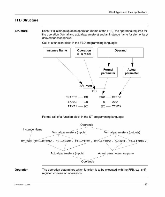
Structure Each FFB is made up of an operation (name of the FFB), the operands required for the operation (formal and actual parameters) and an instance name for elementary/derived function blocks.
Call of a function block in the FBD programming language:
Formal call of a function block in the ST programming language:
Operation The operation determines which function is to be executed with the FFB, e.g. shift register, conversion operations.
Instance Name Operation(FFB name)
Operand
Formal parameter
TON
ENABLE
EXAMP
TIME1
EN
IN
PT
ENO
Q
ET
ERROR
OUT
TIME2
MY_TON
Actual parameter
Instance NameFormal parameters (inputs)
MY_TON (EN:=ENABLE, IN:=EXAMP, PT:=TIME1, ENO=>ERROR, Q=>OUT, ET=>TIME2);
Actual parameters (inputs)
Formal parameters (outputs)
Actual parameters (outputs)
Operands
Operands
31006901 11/2005 17
Block types and their applications
Operand The operand specifies what the operation is to be executed with. With FFBs, this consists of formal and actual parameters.
Formal/actual parameters
Inputs and outputs are required to transfer values to or from an FFB. These are called formal parameters.
Objects are linked to formal parameters; these objects contain the current process states. They are called actual parameters.
At program runtime, the values from the process are transferred to the FFB via the actual parameters and then output again after processing.
The data type of the actual parameters must match the data type of the input/output (formal parameters). The only exceptions are generic inputs/outputs whose data type is determined by the actual parameter. If all actual parameters consist of literals, a suitable data type is selected for the function block.
FFB Call in IL/ST In text languages IL and ST, FFBs can be called in formal and in informal form. Details can be found in the Reference manual.
Example of a formal function call:
out:=LIMIT (MN:=0, IN:=var1, MX:=5) ;
Example of an informal function call:
out:=LIMIT (0, var1, 5) ;
Note: Take note that the use of EN and ENO is only possible for formal calls.
18 31006901 11/2005
Block types and their applications
VAR_IN_OUT variable
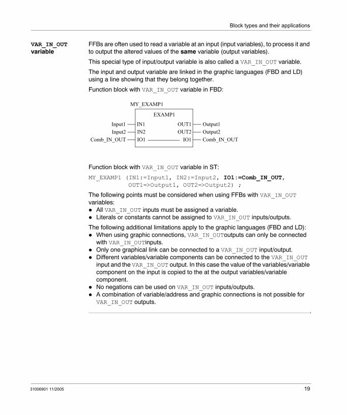
FFBs are often used to read a variable at an input (input variables), to process it and to output the altered values of the same variable (output variables).
This special type of input/output variable is also called a VAR_IN_OUT variable.
The input and output variable are linked in the graphic languages (FBD and LD) using a line showing that they belong together.
Function block with VAR_IN_OUT variable in FBD:
Function block with VAR_IN_OUT variable in ST:
MY_EXAMP1 (IN1:=Input1, IN2:=Input2, IO1:=Comb_IN_OUT,OUT1=>Output1, OUT2=>Output2) ;
The following points must be considered when using FFBs with VAR_IN_OUT variables:
All VAR_IN_OUT inputs must be assigned a variable.Literals or constants cannot be assigned to VAR_IN_OUT inputs/outputs.
The following additional limitations apply to the graphic languages (FBD and LD): When using graphic connections, VAR_IN_OUToutputs can only be connected with VAR_IN_OUTinputs. Only one graphical link can be connected to a VAR_IN_OUT input/output.Different variables/variable components can be connected to the VAR_IN_OUT input and the VAR_IN_OUT output. In this case the value of the variables/variable component on the input is copied to the at the output variables/variable component. No negations can be used on VAR_IN_OUT inputs/outputs.A combination of variable/address and graphic connections is not possible for VAR_IN_OUT outputs.
EXAMP1
Comb_IN_OUTIO1
IN1Input1IN2Input2IO1Comb_IN_OUT
MY_EXAMP1
Output1OUT1Output2OUT2
31006901 11/2005 19
Block types and their applications
EN and ENO
Description An EN input and an ENO output can be configured for all FFBs.
If the value of EN is "0" when the FFB is called up, the algorithms defined by the FFB are not executed and ENO is set to "0".
If the value of EN is "1" when the FFB is called up, the algorithms defined by the FFB are executed. After the algorithms have been executed successfully, the value of ENO is set to "1". If an error occurs when executing these algorithms, ENO is set to "0".
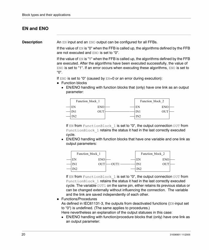
If ENO is set to "0" (caused by EN=0 or an error during execution):Function blocks
EN/ENO handling with function blocks that (only) have one link as an output parameter:
If EN from FunctionBlock_1 is set to "0", the output connection OUT from FunctionBlock_1 retains the status it had in the last correctly executed cycle. EN/ENO handling with function blocks that have one variable and one link as output parameters:
If EN from FunctionBlock_1 is set to "0", the output connection OUT from FunctionBlock_1 retains the status it had in the last correctly executed cycle. The variable OUT1 on the same pin, either retains its previous status or can be changed externally without influencing the connection. The variable and the link are saved independently of each other.
Functions/ProceduresAs defined in IEC61131-3, the outputs from deactivated functions (EN-input set to "0") is undefined. (The same applies to procedures.) Here nevertheless an explanation of the output statuses in this case:
EN/ENO handling with function/procedure blocks that (only) have one link as an output parameter:
Function_block_1
EN
IN2
ENOIN1 OUT
Function_block_2
EN
IN2
ENOIN1 OUT
Function_block_1
EN
IN2
ENOIN1 OUT
Function_block_2
EN
IN2
ENOIN1 OUTOUT1
20 31006901 11/2005
Block types and their applications
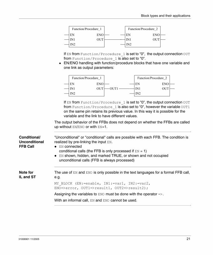
If EN from Function/Procedure_1 is set to "0", the output connection OUT from Function/Procedure_1 is also set to "0".EN/ENO handling with function/procedure blocks that have one variable and one link as output parameters:
If EN from Function/Procedure_1 is set to "0", the output connection OUT from Function/Procedure_1 is also set to "0", however the variable OUT1 on the same pin retains its previous value. In this way it is possible for the variable and the link to have different values.
The output behavior of the FFBs does not depend on whether the FFBs are called up without EN/ENO or with EN=1.
Conditional/Unconditional FFB Call
"Unconditional" or "conditional" calls are possible with each FFB. The condition is realized by pre-linking the input EN.
EN connectedconditional calls (the FFB is only processed if EN = 1)EN shown, hidden, and marked TRUE, or shown and not occupiedunconditional calls (FFB is always processed)
Note for IL and ST
The use of EN and ENO is only possible in the text languages for a formal FFB call, e.g.
MY_BLOCK (EN:=enable, IN1:=var1, IN2:=var2,ENO=>error, OUT1=>result1, OUT2=>result2);
Assigning the variables to ENO must be done with the operator =>.
With an informal call, EN and ENO cannot be used.
Function/Procedure_1
EN
IN2
ENOIN1 OUT
Function/Procedure_2
EN
IN2
ENOIN1 OUT
Function/Procedure_1
EN
IN2
ENOIN1 OUT
Function/Procedure_2
EN
IN2
ENOIN1 OUTOUT1
31006901 11/2005 21

Block types and their applications
22 31006901 11/2005
31006901 11/2005
2
Availability of the blocks on different hardware platformsAvailability of the block on the various hardware platforms
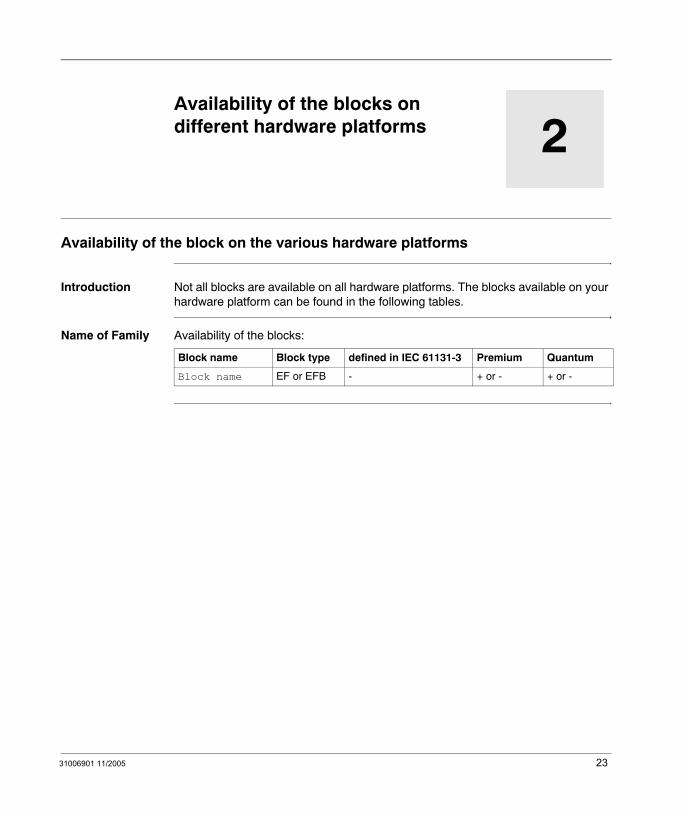
Introduction Not all blocks are available on all hardware platforms. The blocks available on your hardware platform can be found in the following tables.
Name of Family Availability of the blocks:
Block name Block type defined in IEC 61131-3 Premium Quantum
Block name EF or EFB - + or - + or -
23

Availability of the block
24 31006901 11/2005
31006901 11/2005
II
Counters and TimersIntroduction
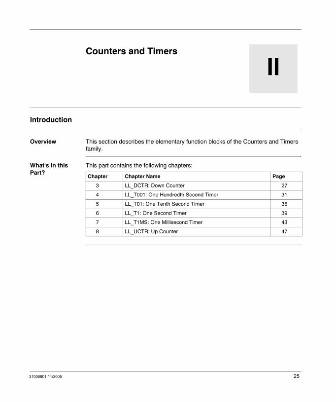
Overview This section describes the elementary function blocks of the Counters and Timers family.
What's in this Part?
This part contains the following chapters:
Chapter Chapter Name Page
3 LL_DCTR: Down Counter 27
4 LL_T001: One Hundredth Second Timer 31
5 LL_T01: One Tenth Second Timer 35
6 LL_T1: One Second Timer 39
7 LL_T1MS: One Millisecond Timer 43
8 LL_UCTR: Up Counter 47
25

Counters and Timers
26 31006901 11/2005
31006901 11/2005
3
LL_DCTR: Down CounterDescription
Function Description
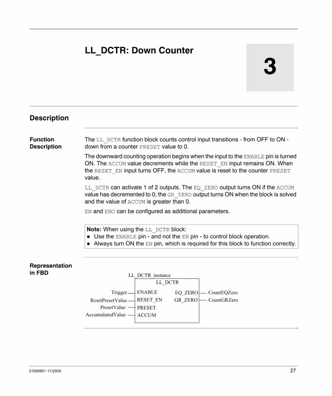
The LL_DCTR function block counts control input transitions - from OFF to ON - down from a counter PRESET value to 0.
The downward counting operation begins when the input to the ENABLE pin is turned ON. The ACCUM value decrements while the RESET_EN input remains ON. When the RESET_EN input turns OFF, the ACCUM value is reset to the counter PRESET value.
LL_DCTR can activate 1 of 2 outputs. The EQ_ZERO output turns ON if the ACCUM value has decremented to 0; the GR_ZERO output turns ON when the block is solved and the value of ACCUM is greater than 0.
EN and ENO can be configured as additional parameters.
Representation in FBD
Note: When using the LL_DCTR block:Use the ENABLE pin - and not the EN pin - to control block operation.Always turn ON the EN pin, which is required for this block to function correctly.
CountEQZero
LL_DCTR
TriggerResetPresetValue
EQ_ZEROENABLERESET_ENPRESET
GR_ZERO
ACCUMPresetValue
CountGRZero
LL_DCTR_instance
AccumulatedValue
27
LL_DCTR
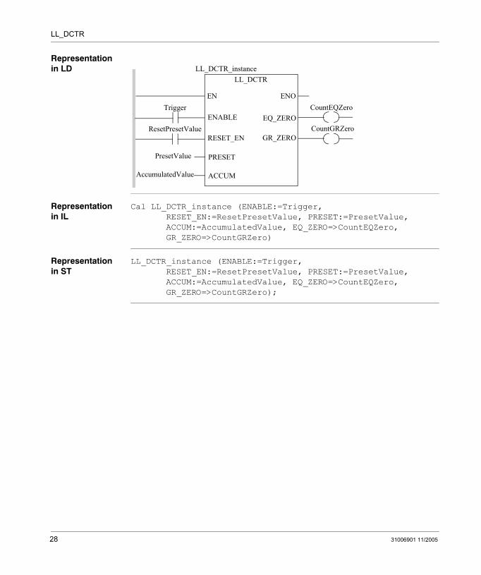
Representation in LD
Representation in IL
Cal LL_DCTR_instance (ENABLE:=Trigger, RESET_EN:=ResetPresetValue, PRESET:=PresetValue,ACCUM:=AccumulatedValue, EQ_ZERO=>CountEQZero,GR_ZERO=>CountGRZero)
Representation in ST
LL_DCTR_instance (ENABLE:=Trigger, RESET_EN:=ResetPresetValue, PRESET:=PresetValue,ACCUM:=AccumulatedValue, EQ_ZERO=>CountEQZero,GR_ZERO=>CountGRZero);
Trigger
ResetPresetValue
ENOENCountEQZero
LL_DCTR
EQ_ZEROENABLE
RESET_EN
PRESET
ACCUM
GR_ZEROCountGRZero
PresetValue
LL_DCTR_instance
AccumulatedValue
28 31006901 11/2005
LL_DCTR
Parameters
Input parameter
Data type 984LL equivalent
Meaning
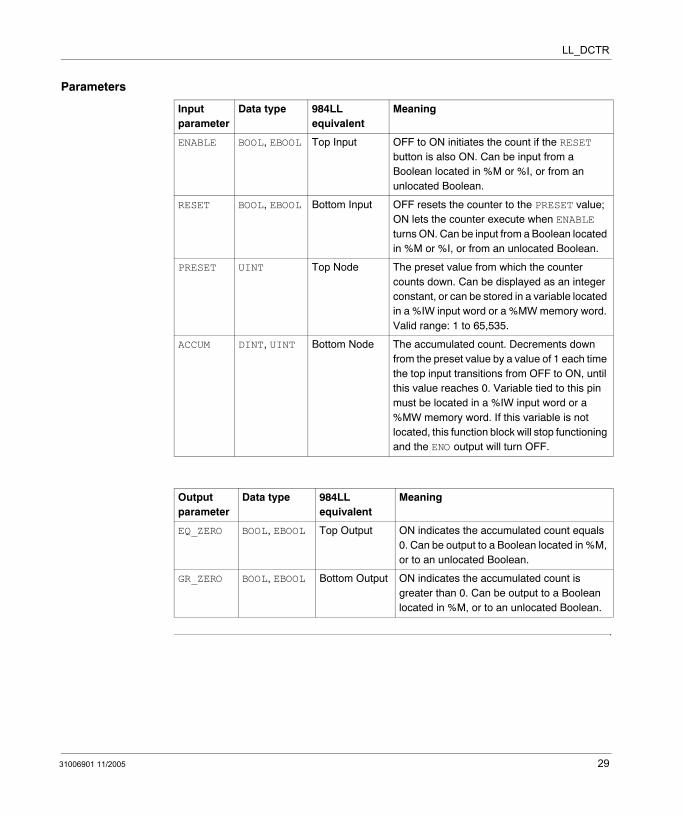
ENABLE BOOL, EBOOL Top Input OFF to ON initiates the count if the RESET button is also ON. Can be input from a Boolean located in %M or %I, or from an unlocated Boolean.
RESET BOOL, EBOOL Bottom Input OFF resets the counter to the PRESET value; ON lets the counter execute when ENABLE turns ON. Can be input from a Boolean located in %M or %I, or from an unlocated Boolean.
PRESET UINT Top Node The preset value from which the counter counts down. Can be displayed as an integer constant, or can be stored in a variable located in a %IW input word or a %MW memory word. Valid range: 1 to 65,535.
ACCUM DINT, UINT Bottom Node The accumulated count. Decrements down from the preset value by a value of 1 each time the top input transitions from OFF to ON, until this value reaches 0. Variable tied to this pin must be located in a %IW input word or a %MW memory word. If this variable is not located, this function block will stop functioning and the ENO output will turn OFF.
Output parameter
Data type 984LL equivalent
Meaning
EQ_ZERO BOOL, EBOOL Top Output ON indicates the accumulated count equals 0. Can be output to a Boolean located in %M, or to an unlocated Boolean.
GR_ZERO BOOL, EBOOL Bottom Output ON indicates the accumulated count is greater than 0. Can be output to a Boolean located in %M, or to an unlocated Boolean.
31006901 11/2005 29

LL_DCTR
30 31006901 11/2005
31006901 11/2005
4
LL_T001: One Hundredth Second TimerDescription
Function Description
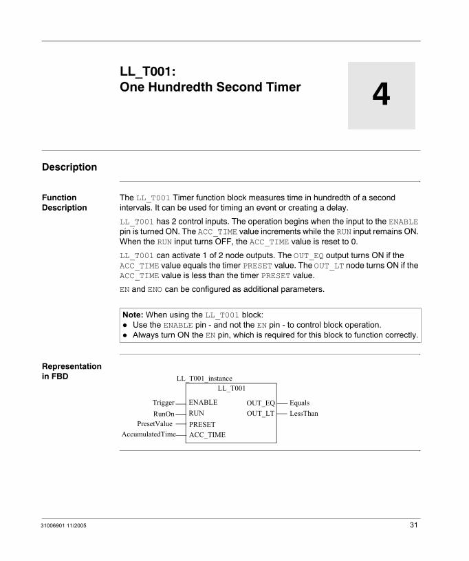
The LL_T001 Timer function block measures time in hundredth of a second intervals. It can be used for timing an event or creating a delay.
LL_T001 has 2 control inputs. The operation begins when the input to the ENABLE pin is turned ON. The ACC_TIME value increments while the RUN input remains ON. When the RUN input turns OFF, the ACC_TIME value is reset to 0.
LL_T001 can activate 1 of 2 node outputs. The OUT_EQ output turns ON if the ACC_TIME value equals the timer PRESET value. The OUT_LT node turns ON if the ACC_TIME value is less than the timer PRESET value.
EN and ENO can be configured as additional parameters.
Representation in FBD
Note: When using the LL_T001 block:Use the ENABLE pin - and not the EN pin - to control block operation.Always turn ON the EN pin, which is required for this block to function correctly.
Equals
LL_T001
TriggerRunOn
OUT_EQENABLERUNPRESET
OUT_LT
ACC_TIMEPresetValue
LessThan
LL_T001_instance
AccumulatedTime
31

LL_T001
Representation in LD
Representation in IL
CAL LL_T001_instance (ENABLE:=Trigger, RUN:=RunOn, PRESET:=PresetValue, ACC_TIME:=AccumulatedTime,OUT_EQ=>Equals, OUT_LT=>LessThan)
Representation in ST
LL_T001_instance (ENABLE:=Trigger, RUN:=RunOn, PRESET:=PresetValue, ACC_TIME:=AccumulatedTime, OUT_EQ=>Equals, OUT_LT=>LessThan);
Trigger
RunOn
ENOENEquals
LL_T001
OUT_EQENABLE
RUN
PRESET
ACC_TIME
OUT_LTLessThan
PresetValue
LL_T001_instance
AccumulatedTime
32 31006901 11/2005
LL_T001
Parameters
Input parameter
Data type 984LL equivalent
Meaning
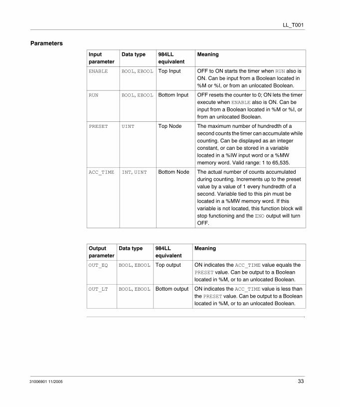
ENABLE BOOL, EBOOL Top Input OFF to ON starts the timer when RUN also is ON. Can be input from a Boolean located in %M or %I, or from an unlocated Boolean.
RUN BOOL, EBOOL Bottom Input OFF resets the counter to 0; ON lets the timer execute when ENABLE also is ON. Can be input from a Boolean located in %M or %I, or from an unlocated Boolean.
PRESET UINT Top Node The maximum number of hundredth of a second counts the timer can accumulate while counting. Can be displayed as an integer constant, or can be stored in a variable located in a %IW input word or a %MW memory word. Valid range: 1 to 65,535.
ACC_TIME INT, UINT Bottom Node The actual number of counts accumulated during counting. Increments up to the preset value by a value of 1 every hundredth of a second. Variable tied to this pin must be located in a %MW memory word. If this variable is not located, this function block will stop functioning and the ENO output will turn OFF.
Output parameter
Data type 984LL equivalent
Meaning
OUT_EQ BOOL, EBOOL Top output ON indicates the ACC_TIME value equals the PRESET value. Can be output to a Boolean located in %M, or to an unlocated Boolean.
OUT_LT BOOL, EBOOL Bottom output ON indicates the ACC_TIME value is less than the PRESET value. Can be output to a Boolean located in %M, or to an unlocated Boolean.
31006901 11/2005 33

LL_T001
34 31006901 11/2005
31006901 11/2005
5
LL_T01: One Tenth Second TimerDescription
Function Description
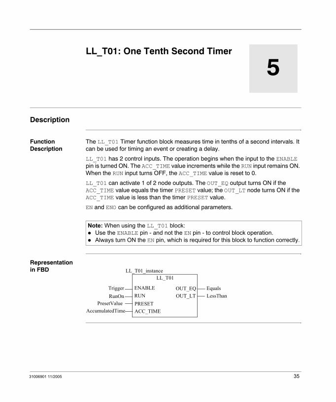
The LL_T01 Timer function block measures time in tenths of a second intervals. It can be used for timing an event or creating a delay.
LL_T01 has 2 control inputs. The operation begins when the input to the ENABLE pin is turned ON. The ACC_TIME value increments while the RUN input remains ON. When the RUN input turns OFF, the ACC_TIME value is reset to 0.
LL_T01 can activate 1 of 2 node outputs. The OUT_EQ output turns ON if the ACC_TIME value equals the timer PRESET value; the OUT_LT node turns ON if the ACC_TIME value is less than the timer PRESET value.
EN and ENO can be configured as additional parameters.
Representation in FBD
Note: When using the LL_T01 block:Use the ENABLE pin - and not the EN pin - to control block operation.Always turn ON the EN pin, which is required for this block to function correctly.
Equals
LL_T01
TriggerRunOn
OUT_EQENABLERUNPRESET
OUT_LT
ACC_TIMEPresetValue
LessThan
LL_T01_instance
AccumulatedTime
35
LL_T01
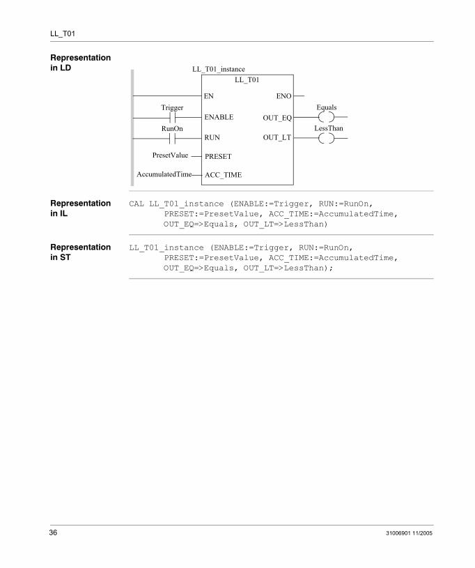
Representation in LD
Representation in IL
CAL LL_T01_instance (ENABLE:=Trigger, RUN:=RunOn, PRESET:=PresetValue, ACC_TIME:=AccumulatedTime, OUT_EQ=>Equals, OUT_LT=>LessThan)
Representation in ST
LL_T01_instance (ENABLE:=Trigger, RUN:=RunOn, PRESET:=PresetValue, ACC_TIME:=AccumulatedTime, OUT_EQ=>Equals, OUT_LT=>LessThan);
Trigger
RunOn
ENOENEquals
LL_T01
OUT_EQENABLE
RUN
PRESET
ACC_TIME
OUT_LTLessThan
PresetValue
LL_T01_instance
AccumulatedTime
36 31006901 11/2005
LL_T01
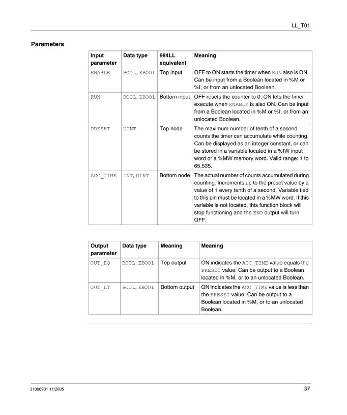
Parameters
Input parameter
Data type 984LL equivalent
Meaning
ENABLE BOOL, EBOOL Top input OFF to ON starts the timer when RUN also is ON. Can be input from a Boolean located in %M or %I, or from an unlocated Boolean.
RUN BOOL, EBOOL Bottom input OFF resets the counter to 0; ON lets the timer execute when ENABLE is also ON. Can be input from a Boolean located in %M or %I, or from an unlocated Boolean.
PRESET UINT Top node The maximum number of tenth of a second counts the timer can accumulate while counting. Can be displayed as an integer constant, or can be stored in a variable located in a %IW input word or a %MW memory word. Valid range: 1 to 65,535.
ACC_TIME INT, UINT Bottom node The actual number of counts accumulated during counting. Increments up to the preset value by a value of 1 every tenth of a second. Variable tied to this pin must be located in a %MW word. If this variable is not located, this function block will stop functioning and the ENO output will turn OFF.
Output parameter
Data type Meaning Meaning
OUT_EQ BOOL, EBOOL Top output ON indicates the ACC_TIME value equals the PRESET value. Can be output to a Boolean located in %M, or to an unlocated Boolean.
OUT_LT BOOL, EBOOL Bottom output ON indicates the ACC_TIME value is less than the PRESET value. Can be output to a Boolean located in %M, or to an unlocated Boolean.
31006901 11/2005 37

LL_T01
38 31006901 11/2005
31006901 11/2005
6
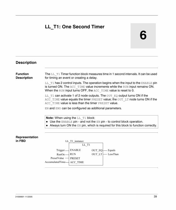
LL_T1: One Second TimerDescription
Function Description
The LL_T1 Timer function block measures time in 1 second intervals. It can be used for timing an event or creating a delay.
LL_T1 has 2 control inputs. The operation begins when the input to the ENABLE pin is turned ON. The ACC_TIME value increments while the RUN input remains ON. When the RUN input turns OFF, the ACC_TIME value is reset to 0.
LL_T1 can activate 1 of 2 node outputs. The OUT_EQ output turns ON if the ACC_TIME value equals the timer PRESET value; the OUT_LT node turns ON if the ACC_TIME value is less than the timer PRESET value.
EN and ENO can be configured as additional parameters.
Representation in FBD
Note: When using the LL_T1 block:Use the ENABLE pin - and not the EN pin - to control block operation.Always turn ON the EN pin, which is required for this block to function correctly.
Equals
LL_T1
TriggerRunOn
OUT_EQENABLERUNPRESET
OUT_LT
ACC_TIMEPresetValue
LessThan
LL_T1_instance
AccumulatedTime
39
LL_T1
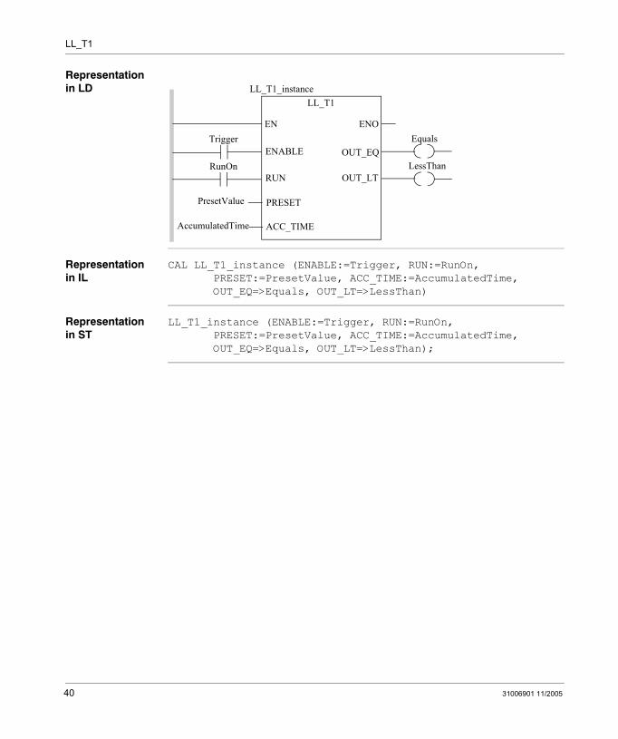
Representation in LD
Representation in IL
CAL LL_T1_instance (ENABLE:=Trigger, RUN:=RunOn, PRESET:=PresetValue, ACC_TIME:=AccumulatedTime, OUT_EQ=>Equals, OUT_LT=>LessThan)
Representation in ST
LL_T1_instance (ENABLE:=Trigger, RUN:=RunOn, PRESET:=PresetValue, ACC_TIME:=AccumulatedTime, OUT_EQ=>Equals, OUT_LT=>LessThan);
Trigger
RunOn
ENOENEquals
LL_T1
OUT_EQENABLE
RUN
PRESET
ACC_TIME
OUT_LTLessThan
PresetValue
LL_T1_instance
AccumulatedTime
40 31006901 11/2005
LL_T1
Parameters
Input parameter
Data type 984LL equivalent
Meaning
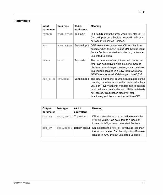
ENABLE BOOL, EBOOL Top input OFF to ON starts the timer when RUN also is ON. Can be input from a Boolean located in %M or %I, or from an unlocated Boolean.
RUN BOOL, EBOOL Bottom input OFF resets the counter to 0; ON lets the timer execute when ENABLE is also ON. Can be input from a Boolean located in %M or %I, or from an unlocated Boolean.
PRESET UINT Top node The maximum number of 1 second counts the timer can accumulate while counting. Can be displayed as an integer constant, or can be stored in a variable located in a %IW input word or a %MW memory word. Valid range: 1 to 65,535.
ACC_TIME INT, UINT Bottom node The actual number of counts accumulated during counting. Increments up to the preset value by a value of 1 every second. Variable tied to this pin must be located in a %MW word. If this variable is not located, this function block will stop functioning and the ENO output will turn OFF.
Output parameter
Data type 984LL equivalent
Meaning
OUT_EQ BOOL, EBOOL Top output ON indicates the ACC_TIME value equals the PRESET value. Can be output to a Boolean located in %M, or to an unlocated Boolean.
OUT_LT BOOL, EBOOL Bottom output ON indicates the ACC_TIME value is less than the PRESET value. Can be output to a Boolean located in %M, or to an unlocated Boolean.
31006901 11/2005 41

LL_T1
42 31006901 11/2005
31006901 11/2005
7
LL_T1MS: One Millisecond TimerDescription
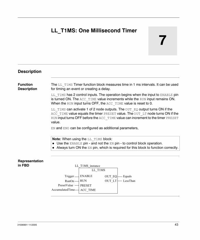
Function Description
The LL_T1MS Timer function block measures time in 1 ms intervals. It can be used for timing an event or creating a delay.
LL_T1MS has 2 control inputs. The operation begins when the input to ENABLE pin is turned ON. The ACC_TIME value increments while the RUN input remains ON. When the RUN input turns OFF, the ACC_TIME value is reset to 0.
LL_T1MS can activate 1 of 2 node outputs. The OUT_EQ output turns ON if the ACC_TIME value equals the timer PRESET value. The OUT_LT node turns ON if the RUN input turns OFF before the ACC_TIME value can increment to the timer PRESET value.
EN and ENO can be configured as additional parameters,
Representation in FBD
Note: When using the LL_T1MS block:Use the ENABLE pin - and not the EN pin - to control block operation.Always turn ON the EN pin, which is required for this block to function correctly.
Equals
LL_T1MS
TriggerRunOn
OUT_EQENABLERUNPRESET
OUT_LT
ACC_TIMEPresetValue
LessThan
LL_T1MS_instance
AccumulatedTime
43
LL_T1MS
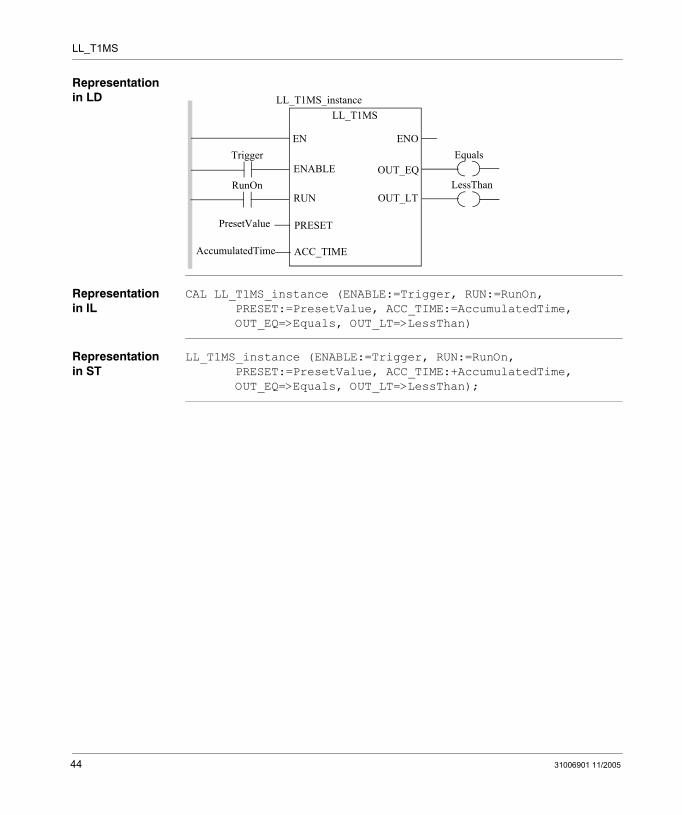
Representation in LD
Representation in IL
CAL LL_T1MS_instance (ENABLE:=Trigger, RUN:=RunOn, PRESET:=PresetValue, ACC_TIME:=AccumulatedTime, OUT_EQ=>Equals, OUT_LT=>LessThan)
Representation in ST
LL_T1MS_instance (ENABLE:=Trigger, RUN:=RunOn, PRESET:=PresetValue, ACC_TIME:+AccumulatedTime, OUT_EQ=>Equals, OUT_LT=>LessThan);
Trigger
RunOn
ENOENEquals
LL_T1MS
OUT_EQENABLE
RUN
PRESET
ACC_TIME
OUT_LTLessThan
PresetValue
LL_T1MS_instance
AccumulatedTime
44 31006901 11/2005
LL_T1MS
Parameters
Input parameter
Data type 984LL equivalent
Meaning
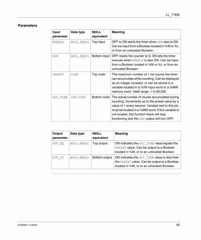
ENABLE BOOL, EBOOL Top input OFF to ON starts the timer when RUN also is ON. Can be input from a Boolean located in %M or %I, or from an unlocated Boolean.
RUN BOOL, EBOOL Bottom input OFF resets the counter to 0; ON lets the timer execute when ENABLE is also ON. Can be input from a Boolean located in %M or %I, or from an unlocated Boolean.
PRESET UINT Top node The maximum number of 1 ms counts the timer can accumulate while counting. Can be displayed as an integer constant, or can be stored in a variable located in a %IW input word or a %MW memory word. Valid range: 1 to 65,535.
ACC_TIME INT, UINT Bottom node The actual number of counts accumulated during counting. Increments up to the preset value by a value of 1 every second. Variable tied to this pin must be located in a %MW word. If this variable is not located, this function block will stop functioning and the ENO output will turn OFF.
Output parameter
Data type 984LL equivalent
Meaning
OUT_EQ BOOL, EBOOL Top output ON indicates the ACC_TIME value equals the PRESET value. Can be output to a Boolean located in %M, or to an unlocated Boolean.
OUT_LT BOOL, EBOOL Bottom output ON indicates the ACC_TIME value is less than the PRESET value. Can be output to a Boolean located in %M, or to an unlocated Boolean.
31006901 11/2005 45

LL_T1MS
46 31006901 11/2005
31006901 11/2005
8
LL_UCTR: Up CounterDescription
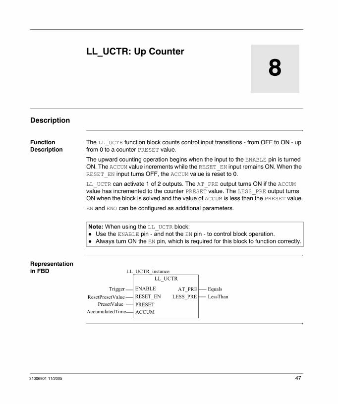
Function Description
The LL_UCTR function block counts control input transitions - from OFF to ON - up from 0 to a counter PRESET value.
The upward counting operation begins when the input to the ENABLE pin is turned ON. The ACCUM value increments while the RESET_EN input remains ON. When the RESET_EN input turns OFF, the ACCUM value is reset to 0.
LL_UCTR can activate 1 of 2 outputs. The AT_PRE output turns ON if the ACCUM value has incremented to the counter PRESET value. The LESS_PRE output turns ON when the block is solved and the value of ACCUM is less than the PRESET value.
EN and ENO can be configured as additional parameters.
Representation in FBD
Note: When using the LL_UCTR block:Use the ENABLE pin - and not the EN pin - to control block operation.Always turn ON the EN pin, which is required for this block to function correctly.
Equals
LL_UCTR
TriggerResetPresetValue
AT_PREENABLERESET_ENPRESET
LESS_PRE
ACCUMPresetValue
LessThan
LL_UCTR_instance
AccumulatedTime
47
LL_UCTR
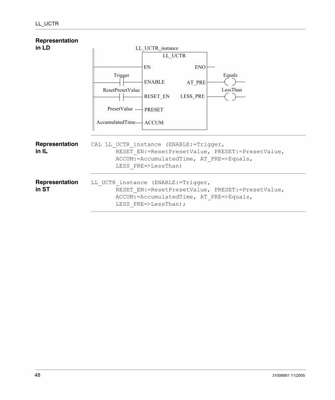
Representation in LD
Representation in IL
CAL LL_UCTR_instance (ENABLE:=Trigger, RESET_EN:=ResetPresetValue, PRESET:=PresetValue, ACCUM:=AccumulatedTime, AT_PRE=>Equals, LESS_PRE=>LessThan)
Representation in ST
LL_UCTR_instance (ENABLE:=Trigger, RESET_EN:=ResetPresetValue, PRESET:=PresetValue, ACCUM:=AccumulatedTime, AT_PRE=>Equals, LESS_PRE=>LessThan);
Trigger
ResetPresetValue
ENOENEquals
LL_UCTR
AT_PREENABLE
RESET_EN
PRESET
ACCUM
LESS_PRELessThan
PresetValue
LL_UCTR_instance
AccumulatedTime
48 31006901 11/2005
LL_UCTR
Parameters
Input parameter
Data type 984LL equivalent
Meaning
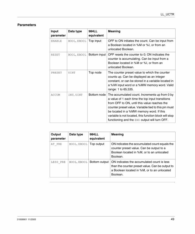
ENABLE BOOL, EBOOL Top input OFF to ON initiates the count. Can be input from a Boolean located in %M or %I, or from an unlocated Boolean.
RESET BOOL, EBOOL Bottom input OFF resets the counter to 0; ON indicates the counter is accumulating. Can be input from a Boolean located in %M or %I, or from an unlocated Boolean.
PRESET UINT Top node The counter preset value to which the counter counts up. Can be displayed as an integer constant, or can be stored in a variable located in a %IW input word or a %MW memory word. Valid range: 1 to 65,535.
ACCUM INT, UINT Bottom node The accumulated count. Increments up from 0 by a value of 1 each time the top input transitions from OFF to ON, until this value reaches the counter preset value. Variable tied to this pin must be located in a %MW memory word. If this variable is not located, this function block will stop functioning and the ENO output will turn OFF.
Output parameter
Data type 984LL equivalent
Meaning
AT_PRE BOOL, EBOOL Top output ON indicates the accumulated count equals the counter preset value. Can be output to a Boolean located in %M, or to an unlocated Boolean.
LESS_PRE BOOL, EBOOL Bottom output ON indicates the accumulated count is less than the counter preset value. Can be output to a Boolean located in %M, or to an unlocated Boolean.
31006901 11/2005 49

LL_UCTR
50 31006901 11/2005
31006901 11/2005
III
MathIntroduction
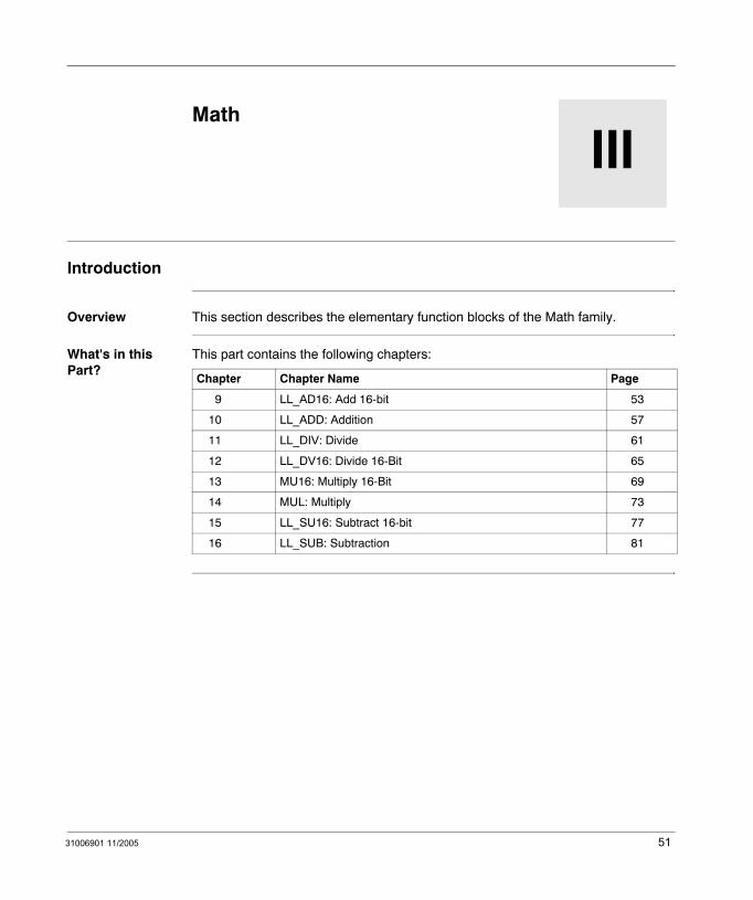
Overview This section describes the elementary function blocks of the Math family.
What's in this Part?
This part contains the following chapters:
Chapter Chapter Name Page
9 LL_AD16: Add 16-bit 53
10 LL_ADD: Addition 57
11 LL_DIV: Divide 61
12 LL_DV16: Divide 16-Bit 65
13 MU16: Multiply 16-Bit 69
14 MUL: Multiply 73
15 LL_SU16: Subtract 16-bit 77
16 LL_SUB: Subtraction 81
51

Math
52 31006901 11/2005
31006901 11/2005
9
LL_AD16: Add 16-bitDescription
Function Description
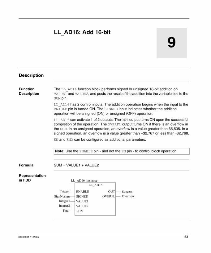
The LL_AD16 function block performs signed or unsigned 16-bit addition on VALUE1 and VALUE2, and posts the result of the addition into the variable tied to the SUM pin.
LL_AD16 has 2 control inputs. The addition operation begins when the input to the ENABLE pin is turned ON. The SIGNED input indicates whether the addition operation will be a signed (ON) or unsigned (OFF) operation.
LL_AD16 can activate 1 of 2 outputs. The OUT output turns ON upon the successful completion of the operation. The OVERFL output turns ON if there is an overflow in the SUM. In an unsigned operation, an overflow is a value greater than 65,535. In a signed operation, an overflow is a value greater than +32,767 or less than -32,768.
EN and ENO can be configured as additional parameters.
Formula SUM = VALUE1 + VALUE2
Representation in FBD
Note: Use the ENABLE pin - and not the EN pin - to control block operation.
LL_AD16
TriggerSignNosign
LL_AD16_Instance
OUTENABLESIGNEDVALUE1VALUE2SUM
Integer1Integer2Total
OVERFLSuccessOverflow
53
LL_AD16
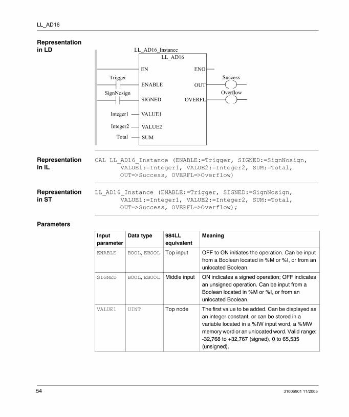
Representation in LD
Representation in IL
CAL LL_AD16_Instance (ENABLE:=Trigger, SIGNED:=SignNosign, VALUE1:=Integer1, VALUE2:=Integer2, SUM:=Total, OUT=>Success, OVERFL=>Overflow)
Representation in ST
LL_AD16_Instance (ENABLE:=Trigger, SIGNED:=SignNosign, VALUE1:=Integer1, VALUE2:=Integer2, SUM:=Total, OUT=>Success, OVERFL=>Overflow);
Parameters
Trigger
SignNosign
ENOENSuccess
LL_AD16LL_AD16_Instance
OUTENABLE
SIGNED
VALUE1
VALUE2
SUM
Integer1
Integer2
Total
OverflowOVERFL
Input parameter
Data type 984LL equivalent
Meaning
ENABLE BOOL, EBOOL Top input OFF to ON initiates the operation. Can be input from a Boolean located in %M or %I, or from an unlocated Boolean.
SIGNED BOOL, EBOOL Middle input ON indicates a signed operation; OFF indicates an unsigned operation. Can be input from a Boolean located in %M or %I, or from an unlocated Boolean.
VALUE1 UINT Top node The first value to be added. Can be displayed as an integer constant, or can be stored in a variable located in a %IW input word, a %MW memory word or an unlocated word. Valid range: -32,768 to +32,767 (signed), 0 to 65,535 (unsigned).
54 31006901 11/2005
LL_AD16
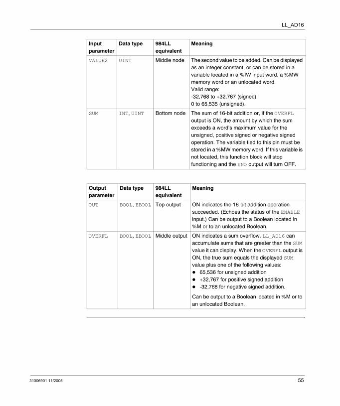
VALUE2 UINT Middle node The second value to be added. Can be displayed as an integer constant, or can be stored in a variable located in a %IW input word, a %MW memory word or an unlocated word. Valid range: -32,768 to +32,767 (signed) 0 to 65,535 (unsigned).
SUM INT, UINT Bottom node The sum of 16-bit addition or, if the OVERFL output is ON, the amount by which the sum exceeds a word’s maximum value for the unsigned, positive signed or negative signed operation. The variable tied to this pin must be stored in a %MW memory word. If this variable is not located, this function block will stop functioning and the ENO output will turn OFF.
Output parameter
Data type 984LL equivalent
Meaning
OUT BOOL, EBOOL Top output ON indicates the 16-bit addition operation succeeded. (Echoes the status of the ENABLE input.) Can be output to a Boolean located in %M or to an unlocated Boolean.
OVERFL BOOL, EBOOL Middle output ON indicates a sum overflow. LL_AD16 can accumulate sums that are greater than the SUM value it can display. When the OVERFL output is ON, the true sum equals the displayed SUM value plus one of the following values:
65,536 for unsigned addition+32,767 for positive signed addition-32,768 for negative signed addition.
Can be output to a Boolean located in %M or to an unlocated Boolean.
Input parameter
Data type 984LL equivalent
Meaning
31006901 11/2005 55

LL_AD16
56 31006901 11/2005
31006901 11/2005
10
LL_ADD: AdditionDescription
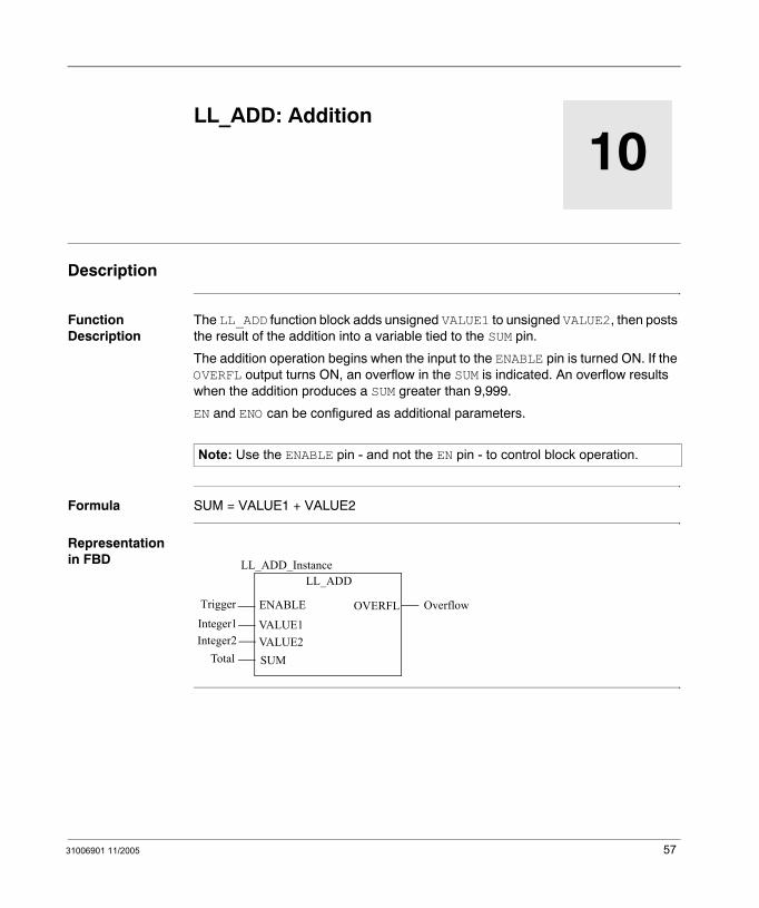
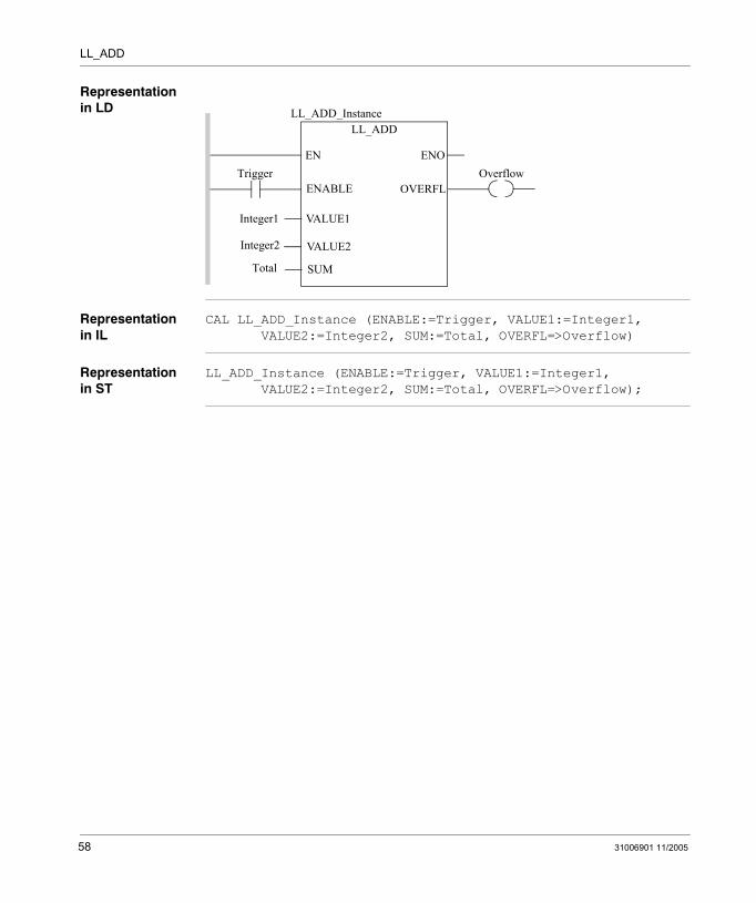
Function Description
The LL_ADD function block adds unsigned VALUE1 to unsigned VALUE2, then posts the result of the addition into a variable tied to the SUM pin.
The addition operation begins when the input to the ENABLE pin is turned ON. If the OVERFL output turns ON, an overflow in the SUM is indicated. An overflow results when the addition produces a SUM greater than 9,999.
EN and ENO can be configured as additional parameters.
Formula SUM = VALUE1 + VALUE2
Representation in FBD
Note: Use the ENABLE pin - and not the EN pin - to control block operation.
LL_ADD
Trigger
LL_ADD_Instance
ENABLE
VALUE1VALUE2SUM
Integer1Integer2Total
OVERFL Overflow
57
LL_ADD
Representation in LD
Representation in IL
CAL LL_ADD_Instance (ENABLE:=Trigger, VALUE1:=Integer1, VALUE2:=Integer2, SUM:=Total, OVERFL=>Overflow)
Representation in ST
LL_ADD_Instance (ENABLE:=Trigger, VALUE1:=Integer1, VALUE2:=Integer2, SUM:=Total, OVERFL=>Overflow);
TriggerENOEN
LL_ADDLL_ADD_Instance
ENABLE
VALUE1
VALUE2
SUM
Integer1
Integer2
Total
OverflowOVERFL
58 31006901 11/2005
LL_ADD
Parameters
Input parameter
Data type 984LL equivalent
Meaning
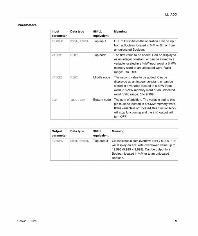
ENABLE BOOL,EBOOL Top input OFF to ON initiates the operation. Can be input from a Boolean located in %M or %I, or from an unlocated Boolean.
VALUE1 UINT Top node The first value to be added. Can be displayed as an integer constant, or can be stored in a variable located in a %IW input word, a %MW memory word or an unlocated word. Valid range: 0 to 9,999.
VALUE2 UINT Middle node The second value to be added. Can be displayed as an integer constant, or can be stored in a variable located in a %IW input word, a %MW memory word or an unlocated word. Valid range: 0 to 9,999.
SUM INT, UINT Bottom node The sum of addition. The variable tied to this pin must be located in a %MW memory word. If this variable is not located, this function block will stop functioning and the ENO output will turn OFF.
Output parameter
Data type 984LL equivalent
Meaning
OVERFL BOOL, EBOOL Top output ON indicates a sum overflow: SUM > 9,999. SUM will display an accurate overflowed value up to 19,998 (9,999 + 9,999). Can be output to a Boolean located in %M or to an unlocated Boolean.
31006901 11/2005 59

LL_ADD
60 31006901 11/2005
31006901 11/2005
11
LL_DIV: DivideDescription
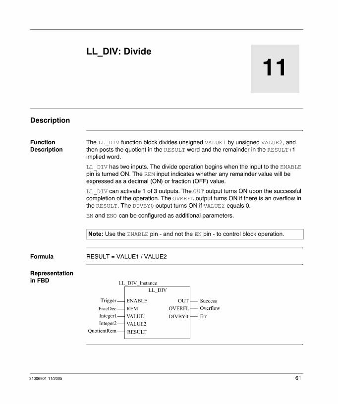
Function Description
The LL_DIV function block divides unsigned VALUE1 by unsigned VALUE2, and then posts the quotient in the RESULT word and the remainder in the RESULT+1 implied word.
LL_DIV has two inputs. The divide operation begins when the input to the ENABLE pin is turned ON. The REM input indicates whether any remainder value will be expressed as a decimal (ON) or fraction (OFF) value.
LL_DIV can activate 1 of 3 outputs. The OUT output turns ON upon the successful completion of the operation. The OVERFL output turns ON if there is an overflow in the RESULT. The DIVBY0 output turns ON if VALUE2 equals 0.
EN and ENO can be configured as additional parameters.
Formula RESULT = VALUE1 / VALUE2
Representation in FBD
Note: Use the ENABLE pin - and not the EN pin - to control block operation.
LL_DIV
TriggerFracDec
LL_DIV_Instance
OUTENABLEREMVALUE1VALUE2RESULT
Integer1Integer2
QuotientRem
OVERFLSuccessOverflow
DIVBY0 Err
61
LL_DIV
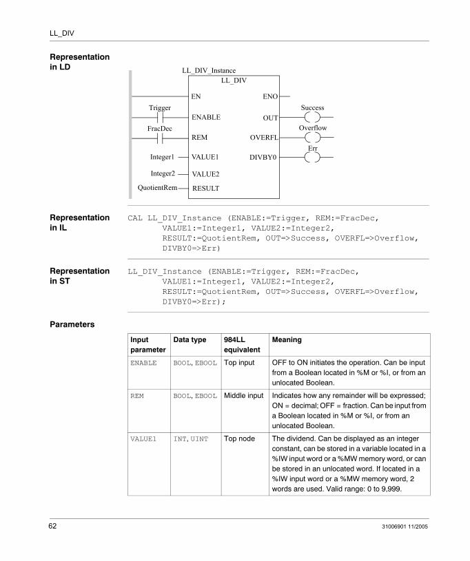
Representation in LD
Representation in IL
CAL LL_DIV_Instance (ENABLE:=Trigger, REM:=FracDec, VALUE1:=Integer1, VALUE2:=Integer2, RESULT:=QuotientRem, OUT=>Success, OVERFL=>Overflow, DIVBY0=>Err)
Representation in ST
LL_DIV_Instance (ENABLE:=Trigger, REM:=FracDec, VALUE1:=Integer1, VALUE2:=Integer2, RESULT:=QuotientRem, OUT=>Success, OVERFL=>Overflow, DIVBY0=>Err);
Parameters
Trigger
FracDec
ENOENSuccess
LL_DIVLL_DIV_Instance
OUTENABLE
REM
VALUE1
VALUE2
RESULT
Integer1
Integer2
QuotientRem
OverflowOVERFL
DIVBY0Err
Input parameter
Data type 984LL equivalent
Meaning
ENABLE BOOL, EBOOL Top input OFF to ON initiates the operation. Can be input from a Boolean located in %M or %I, or from an unlocated Boolean.
REM BOOL, EBOOL Middle input Indicates how any remainder will be expressed; ON = decimal; OFF = fraction. Can be input from a Boolean located in %M or %I, or from an unlocated Boolean.
VALUE1 INT, UINT Top node The dividend. Can be displayed as an integer constant, can be stored in a variable located in a %IW input word or a %MW memory word, or can be stored in an unlocated word. If located in a %IW input word or a %MW memory word, 2 words are used. Valid range: 0 to 9,999.
62 31006901 11/2005
LL_DIV
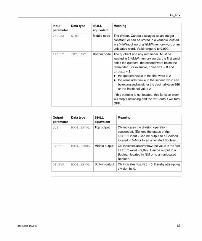
VALUE2 UINT Middle node The divisor. Can be displayed as an integer constant, or can be stored in a variable located in a %IW input word, a %MW memory word or an unlocated word. Valid range: 0 to 9,999.
RESULT INT, UINT Bottom node The quotient and any remainder. Must be located in 2 %MW memory words; the first word holds the quotient, the second word holds the remainder. For example, if VALUE1 = 8 and VALUE2 = 3:
the quotient value in the first word is 2the remainder value in the second word can be expressed as either the decimal value 666 or the fractional value 2.
If this variable is not located, this function block will stop functioning and the ENO output will turn OFF.
Output parameter
Data type 984LL equivalent
Meaning
OUT BOOL, EBOOL Top output ON indicates the division operation succeeded. (Echoes the status of the ENABLE input.) Can be output to a Boolean located in %M or to an unlocated Boolean.
OVERFL BOOL, EBOOL Middle output ON indicates an overflow: the value in the first RESULT word > 9,999. Can be output to a Boolean located in %M or to an unlocated Boolean.
DIVBY0 BOOL, EBOOL Bottom output ON indicates VALUE2 = 0, thereby attempting division by 0.
Input parameter
Data type 984LL equivalent
Meaning
31006901 11/2005 63

LL_DIV
64 31006901 11/2005
31006901 11/2005
12
LL_DV16: Divide 16-BitDescription
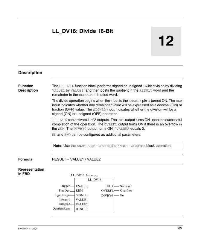
Function Description
The LL_DV16 function block performs signed or unsigned 16-bit division by dividing VALUE1 by VALUE2, and then posts the quotient in the RESULT word and the remainder in the RESULT+1 implied word.
The divide operation begins when the input to the ENABLE pin is turned ON. The REM input indicates whether any remainder value will be expressed as a decimal (ON) or fraction (OFF) value. The SIGNED input indicates whether the division will be a signed (ON) or unsigned (OFF) operation.
LL_DV16 can activate 1 of 3 outputs. The OUT output turns ON upon the successful completion of the operation. The OVERFL output turns ON if there is an overflow in the SUM. The DIVBY0 output turns ON if VALUE2 equals 0.
EN and ENO can be configured as additional parameters.
Formula RESULT = VALUE1 / VALUE2
Representation in FBD
Note: Use the ENABLE pin - and not the EN pin - to control block operation.
LL_DV16
TriggerFracDec
LL_DV16_Instance
OUTENABLEREM
VALUE1VALUE2RESULT
Integer1Integer2
QuotientRem
OVERFLSuccessOverflow
DIVBY0 ErrSignUnsign SIGNED
65
LL_DV16
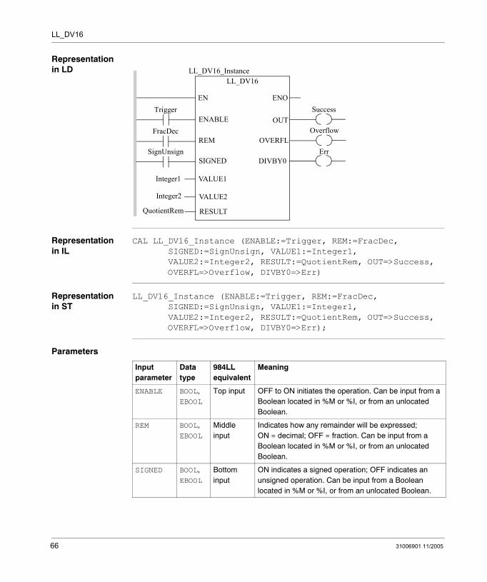
Representation in LD
Representation in IL
CAL LL_DV16_Instance (ENABLE:=Trigger, REM:=FracDec, SIGNED:=SignUnsign, VALUE1:=Integer1, VALUE2:=Integer2, RESULT:=QuotientRem, OUT=>Success, OVERFL=>Overflow, DIVBY0=>Err)
Representation in ST
LL_DV16_Instance (ENABLE:=Trigger, REM:=FracDec, SIGNED:=SignUnsign, VALUE1:=Integer1, VALUE2:=Integer2, RESULT:=QuotientRem, OUT=>Success, OVERFL=>Overflow, DIVBY0=>Err);
Parameters
Trigger
FracDec
ENOENSuccess
LL_DV16LL_DV16_Instance
OUTENABLE
REM
VALUE1
VALUE2
RESULT
Integer1
Integer2
QuotientRem
OverflowOVERFL
DIVBY0ErrSignUnsign
SIGNED
Input parameter
Data type
984LL equivalent
Meaning
ENABLE BOOL, EBOOL
Top input OFF to ON initiates the operation. Can be input from a Boolean located in %M or %I, or from an unlocated Boolean.
REM BOOL, EBOOL
Middle input
Indicates how any remainder will be expressed; ON = decimal; OFF = fraction. Can be input from a Boolean located in %M or %I, or from an unlocated Boolean.
SIGNED BOOL, EBOOL
Bottom input
ON indicates a signed operation; OFF indicates an unsigned operation. Can be input from a Boolean located in %M or %I, or from an unlocated Boolean.
66 31006901 11/2005
LL_DV16
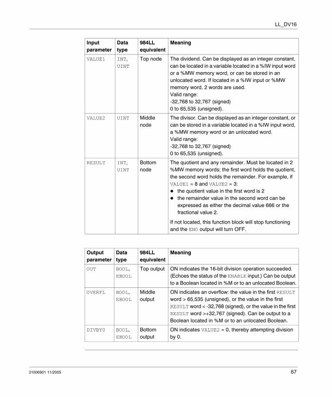
VALUE1 INT, UINT
Top node The dividend. Can be displayed as an integer constant, can be located in a variable located in a %IW input word or a %MW memory word, or can be stored in an unlocated word. If located in a %IW input or %MW memory word, 2 words are used. Valid range:-32,768 to 32,767 (signed)0 to 65,535 (unsigned).
VALUE2 UINT Middle node
The divisor. Can be displayed as an integer constant, or can be stored in a variable located in a %IW input word, a %MW memory word or an unlocated word. Valid range: -32,768 to 32,767 (signed)0 to 65,535 (unsigned).
RESULT INT, UINT
Bottom node
The quotient and any remainder. Must be located in 2 %MW memory words; the first word holds the quotient, the second word holds the remainder. For example, if VALUE1 = 8 and VALUE2 = 3:
the quotient value in the first word is 2the remainder value in the second word can be expressed as either the decimal value 666 or the fractional value 2.
If not located, this function block will stop functioning and the ENO output will turn OFF.
Output parameter
Data type
984LL equivalent
Meaning
OUT BOOL, EBOOL
Top output ON indicates the 16-bit division operation succeeded. (Echoes the status of the ENABLE input.) Can be output to a Boolean located in %M or to an unlocated Boolean.
OVERFL BOOL, EBOOL
Middle output
ON indicates an overflow: the value in the first RESULT word > 65,535 (unsigned), or the value in the first RESULT word < -32,768 (signed), or the value in the first RESULT word >+32,767 (signed). Can be output to a Boolean located in %M or to an unlocated Boolean.
DIVBY0 BOOL, EBOOL
Bottom output
ON indicates VALUE2 = 0, thereby attempting division by 0.
Input parameter
Data type
984LL equivalent
Meaning
31006901 11/2005 67

LL_DV16
68 31006901 11/2005
31006901 11/2005
13
MU16: Multiply 16-BitDescription
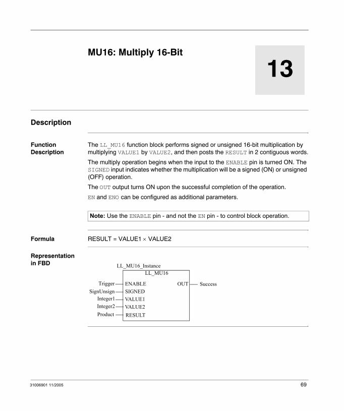
Function Description
The LL_MU16 function block performs signed or unsigned 16-bit multiplication by multiplying VALUE1 by VALUE2, and then posts the RESULT in 2 contiguous words.
The multiply operation begins when the input to the ENABLE pin is turned ON. The SIGNED input indicates whether the multiplication will be a signed (ON) or unsigned (OFF) operation.
The OUT output turns ON upon the successful completion of the operation.
EN and ENO can be configured as additional parameters.
Formula RESULT = VALUE1 × VALUE2
Representation in FBD
Note: Use the ENABLE pin - and not the EN pin - to control block operation.
LL_MU16
Trigger
LL_MU16_Instance
OUTENABLE
VALUE1VALUE2RESULT
Integer1Integer2Product
SuccessSignUnsign SIGNED
69
LL_MU16
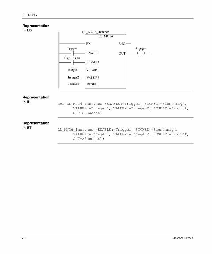
Representation in LD
Representation in IL
CAL LL_MU16_Instance (ENABLE:=Trigger, SIGNED:=SignUnsign, VALUE1:=Integer1, VALUE2:=Integer2, RESULT:=Product, OUT=>Success)
Representation in ST
LL_MU16_Instance (ENABLE:=Trigger, SIGNED:=SignUnsign, VALUE1:=Integer1, VALUE2:=Integer2, RESULT:=Product, OUT=>Success);
TriggerENOEN
Success
LL_MU16LL_MU16_Instance
OUTENABLE
VALUE1
VALUE2
RESULT
Integer1
Integer2
Product
SignUnsignSIGNED
70 31006901 11/2005
LL_MU16
Parameters
Input parameter
Data type
984LL equivalent
Meaning
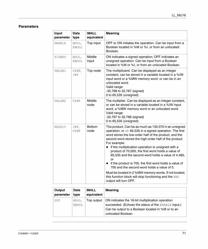
ENABLE BOOL, EBOOL
Top input OFF to ON initiates the operation. Can be input from a Boolean located in %M or %I, or from an unlocated Boolean.
SIGNED BOOL, EBOOL
Middle input
ON indicates a signed operation; OFF indicates an unsigned operation. Can be input from a Boolean located in %M or %I, or from an unlocated Boolean.
VALUE1 UINT, INT
Top node The multiplicand. Can be displayed as an integer constant, can be stored in a variable located in a %IW input word or a %MW memory word, or can be in an unlocated word. Valid range:-32,768 to 32,767 (signed)0 to 65,535 (unsigned).
VALUE2 UINT Middle node
The multiplier. Can be displayed as an integer constant, or can be stored in a variable located in a %IW input word, a %MW memory word or an unlocated word. Valid range:-32,767 to 32,768 (signed)0 to 65,535 (unsigned).
RESULT INT, UINT
Bottom node
The product. Can be as much as 130,070 in an unsigned operation, or +/- 65,535 in a signed operation. The first word stores the low-order half of the product, and the second word stored the high-order half of the product. For example:
if the multiplication operation is unsigned with a product of 70,000, the first word holds a value of 65,535 and the second word holds a value of 4,465, orif the product is 700, the first word holds a value of 700 and the second word holds a value of 0.
Must be located in 2 %MW memory words. If not located, this function block will stop functioning and the ENO output will turn OFF.
Output parameter
Data type
984LL equivalent
Meaning
OUT BOOL, EBOOL
Top output ON indicates the 16-bit multiplication operation succeeded. (Echoes the status of the ENABLE input.) Can be output to a Boolean located in %M or to an unlocated Boolean.
31006901 11/2005 71

LL_MU16
72 31006901 11/2005
31006901 11/2005
14
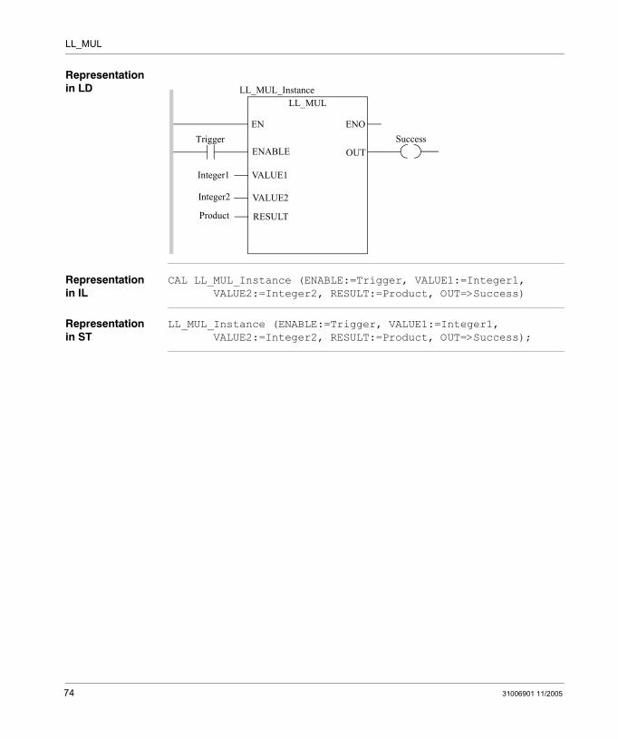
MUL: MultiplyDescription
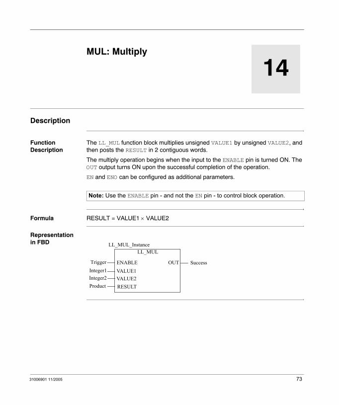
Function Description
The LL_MUL function block multiplies unsigned VALUE1 by unsigned VALUE2, and then posts the RESULT in 2 contiguous words.
The multiply operation begins when the input to the ENABLE pin is turned ON. The OUT output turns ON upon the successful completion of the operation.
EN and ENO can be configured as additional parameters.
Formula RESULT = VALUE1 × VALUE2
Representation in FBD
Note: Use the ENABLE pin - and not the EN pin - to control block operation.
LL_MUL
Trigger
LL_MUL_Instance
OUTENABLEVALUE1VALUE2RESULT
Integer1Integer2Product
Success
73
LL_MUL
Representation in LD
Representation in IL
CAL LL_MUL_Instance (ENABLE:=Trigger, VALUE1:=Integer1, VALUE2:=Integer2, RESULT:=Product, OUT=>Success)
Representation in ST
LL_MUL_Instance (ENABLE:=Trigger, VALUE1:=Integer1, VALUE2:=Integer2, RESULT:=Product, OUT=>Success);
TriggerENOEN
Success
LL_MULLL_MUL_Instance
OUTENABLE
VALUE1
VALUE2
RESULT
Integer1
Integer2
Product
74 31006901 11/2005
LL_MUL
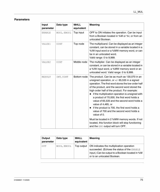
Parameters
Input parameter
Data type 984LL equivalent
Meaning
ENABLE BOOL, EBOOL Top input OFF to ON initiates the operation. Can be input from a Boolean located in %M or %I, or from an unlocated Boolean.
VALUE1 UINT Top node The multiplicand. Can be displayed as an integer constant, can be stored in a variable located in a %IW input word or a %MW memory word, or can be in an unlocated word. Valid range: 0 to 9,999.
VALUE2 UINT Middle node The multiplier. Can be displayed as an integer constant, or can be stored in a variable located in a %IW input word, a %MW memory word or an unlocated word. Valid range: 0 to 9,999.
RESULT INT, UINT Bottom node The product. Can be as much as 130,070 in an unsigned operation, or +/- 65,535 in a signed operation. The first word stores the low-order half of the product, and the second word stored the high-order half of the product. For example:
if the multiplication operation is unsigned with a product of 70,000, the first word holds a value of 65,535 and the second word holds a value of 4,465, orif the product is 700, the first word holds a value of 700 and the second word holds a value of 0.
Must be located in 2 %MW memory words. If not located, this function block will stop functioning and the ENO output will turn OFF.
Output parameter
Data type 984LL equivalent
Meaning
OUT BOOL, EBOOL Top output ON indicates the multiplication operation succeeded. (Echoes the status of the ENABLE input.) Can be output to a Boolean located in %M or to an unlocated Boolean.
31006901 11/2005 75

LL_MUL
76 31006901 11/2005
31006901 11/2005
15
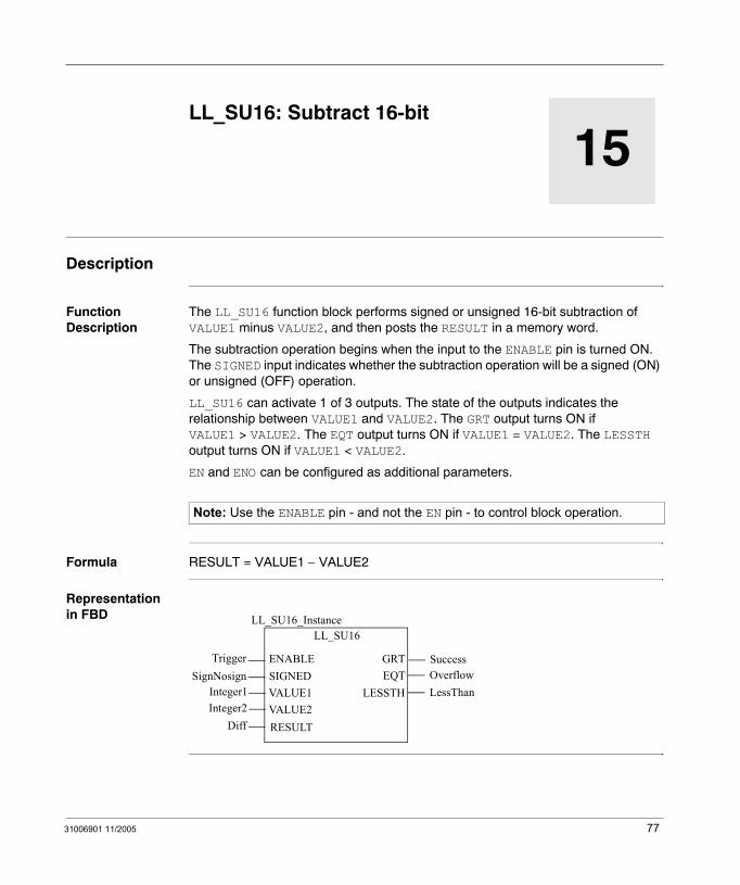
LL_SU16: Subtract 16-bitDescription
Function Description
The LL_SU16 function block performs signed or unsigned 16-bit subtraction of VALUE1 minus VALUE2, and then posts the RESULT in a memory word.
The subtraction operation begins when the input to the ENABLE pin is turned ON. The SIGNED input indicates whether the subtraction operation will be a signed (ON) or unsigned (OFF) operation.
LL_SU16 can activate 1 of 3 outputs. The state of the outputs indicates the relationship between VALUE1 and VALUE2. The GRT output turns ON if VALUE1 > VALUE2. The EQT output turns ON if VALUE1 = VALUE2. The LESSTH output turns ON if VALUE1 < VALUE2.
EN and ENO can be configured as additional parameters.
Formula RESULT = VALUE1 − VALUE2
Representation in FBD
Note: Use the ENABLE pin - and not the EN pin - to control block operation.
LL_SU16
TriggerSignNosign
LL_SU16_Instance
GRTENABLESIGNEDVALUE1VALUE2RESULT
Integer1Integer2
Diff
EQTSuccessOverflow
LESSTH LessThan
77
LL_SU16
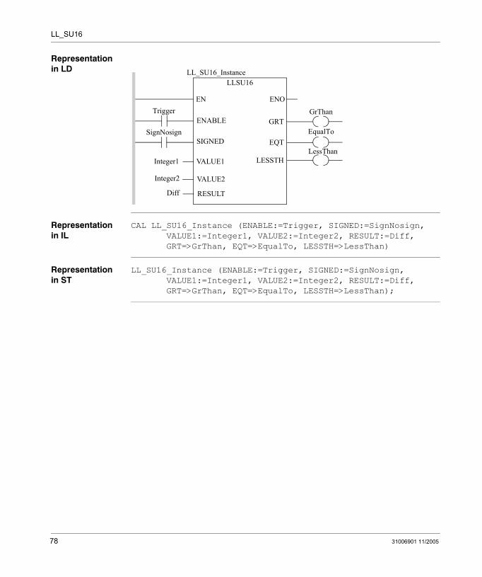
Representation in LD
Representation in IL
CAL LL_SU16_Instance (ENABLE:=Trigger, SIGNED:=SignNosign, VALUE1:=Integer1, VALUE2:=Integer2, RESULT:=Diff, GRT=>GrThan, EQT=>EqualTo, LESSTH=>LessThan)
Representation in ST
LL_SU16_Instance (ENABLE:=Trigger, SIGNED:=SignNosign, VALUE1:=Integer1, VALUE2:=Integer2, RESULT:=Diff, GRT=>GrThan, EQT=>EqualTo, LESSTH=>LessThan);
Trigger
SignNosign
ENOEN
LLSU16LL_SU16_Instance
ENABLE
SIGNED
VALUE1
VALUE2
RESULT
Integer1
Integer2
Diff
GrThanGRT
EqualToEQT
LESSTHLessThan
78 31006901 11/2005
LL_SU16
Parameters
Input parameter
Data type
984LL equivalent
Meaning
ENABLE BOOL, EBOOL
Top input OFF to ON initiates the operation. Can be input from a Boolean located in %M or %I, or from an unlocated Boolean.
SIGNED BOOL, EBOOL
Middle input
ON indicates a signed operation; OFF indicates an unsigned operation. Can be input from a Boolean located in %M or %I, or from an unlocated Boolean.
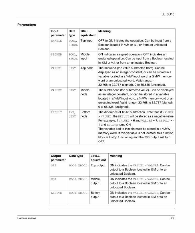
VALUE1 UINT Top node The minuend (the value subtracted from). Can be displayed as an integer constant, or can be stored in a variable located in a %IW input word, a %MW memory word or an unlocated word. Valid range: -32,768 to 32,767 (signed), 0 to 65,535 (unsigned).
VALUE2 UINT Middle node
The subtrahend (the subtracted value). Can be displayed as an integer constant, or can be stored in a variable located in a %IW input word, a %MW memory word or an unlocated word. Valid range: -32,768 to 32,767 (signed). 0 to 65,535 (unsigned).
RESULT INT, UINT
Bottom node
The difference of 16-bit subtraction. Note that, if VALUE2 > VALUE1, the RESULT will be stored as a negative value For example, if VALUE1 = 6 and VALUE2 = 7, RESULT = -1 and LESSTH turns ONThe variable tied to this pin must be stored in a %MW memory word. If this variable is not located, this function block will stop functioning and the ENO output will turn OFF.
Output parameter
Data type 984LL equivalent
Meaning
GRT BOOL, EBOOL Top output ON indicates the VALUE1 > VALUE2. Can be output to a Boolean located in %M or to an unlocated Boolean.
EQT BOOL, EBOOL Middle output
ON indicates the VALUE1 = VALUE2. Can be output to a Boolean located in %M or to an unlocated Boolean.
LESSTH BOOL, EBOOL Bottom output
ON indicates the VALUE1 < VALUE2. Can be output to a Boolean located in %M or to an unlocated Boolean.
31006901 11/2005 79

LL_SU16
80 31006901 11/2005
31006901 11/2005
16
LL_SUB: SubtractionDescription
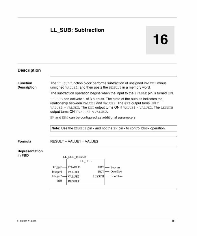
Function Description
The LL_SUB function block performs subtraction of unsigned VALUE1 minus unsigned VALUE2, and then posts the RESULT in a memory word.
The subtraction operation begins when the input to the ENABLE pin is turned ON.
LL_SUB can activate 1 of 3 outputs. The state of the outputs indicates the relationship between VALUE1 and VALUE2. The GRT output turns ON if VALUE1 > VALUE2. The EQT output turns ON if VALUE1 = VALUE2. The LESSTH output turns ON if VALUE1 < VALUE2.
EN and ENO can be configured as additional parameters.
Formula RESULT = VALUE1 − VALUE2
Representation in FBD
Note: Use the ENABLE pin - and not the EN pin - to control block operation.
LL_SUB
Trigger
LL_SUB_Instance
GRTENABLEVALUE1VALUE2RESULT
Integer1Integer2
Diff
EQTSuccessOverflow
LESSTH LessThan
81
LL_SUB
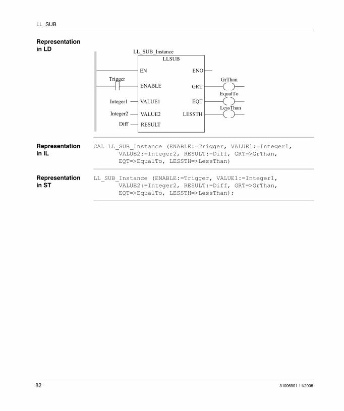
Representation in LD
Representation in IL
CAL LL_SUB_Instance (ENABLE:=Trigger, VALUE1:=Integer1, VALUE2:=Integer2, RESULT:=Diff, GRT=>GrThan, EQT=>EqualTo, LESSTH=>LessThan)
Representation in ST
LL_SUB_Instance (ENABLE:=Trigger, VALUE1:=Integer1, VALUE2:=Integer2, RESULT:=Diff, GRT=>GrThan, EQT=>EqualTo, LESSTH=>LessThan);
TriggerENOEN
LLSUBLL_SUB_Instance
ENABLE
VALUE1
VALUE2
RESULT
Integer1
Integer2
Diff
GrThanGRT
EqualToEQT
LESSTHLessThan
82 31006901 11/2005
LL_SUB
Parameters
Input parameter
Data type 984LL equivalent
Meaning
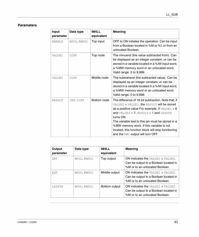
ENABLE BOOL, EBOOL Top input OFF to ON initiates the operation. Can be input from a Boolean located in %M or %I, or from an unlocated Boolean.
VALUE1 UINT Top node The minuend (the value subtracted from). Can be displayed as an integer constant, or can be stored in a variable located in a %IW input word, a %MW memory word or an unlocated word. Valid range: 0 to 9,999.
VALUE2 UINT Middle node The subtrahend (the subtracted value). Can be displayed as an integer constant, or can be stored in a variable located in a %IW input word, a %MW memory word or an unlocated word. Valid range: 0 to 9,999.
RESULT INT, UINT Bottom node The difference of 16-bit subtraction. Note that, if VALUE2 > VALUE1, the RESULT will be stored as a positive value For example, if VALUE1 = 6 and VALUE2 = 7, RESULT = 1 and LESSTH turns ON.The variable tied to this pin must be stored in a %MW memory word. If this variable is not located, this function block will stop functioning and the ENO output will turn OFF.
Output parameter
Data type 984LL equivalent
Meaning
GRT BOOL, EBOOL Top output ON indicates the VALUE1 > VALUE2. Can be output to a Boolean located in %M or to an unlocated Boolean.
EQT BOOL, EBOOL Middle output ON indicates the VALUE1 = VALUE2. Can be output to a Boolean located in %M or to an unlocated Boolean.
LESSTH BOOL, EBOOL Bottom output ON indicates the VALUE1 < VALUE2. Can be output to a Boolean located in %M or to an unlocated Boolean.
31006901 11/2005 83

LL_SUB
84 31006901 11/2005
31006901 11/2005
IV
MatrixIntroduction
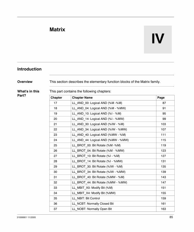
Overview This section describes the elementary function blocks of the Matrix family.
What's in this Part?
This part contains the following chapters:
Chapter Chapter Name Page
17 LL_AND_00: Logical AND (%M -%M) 87
18 LL_AND_04: Logical AND (%M - %MW) 91
19 LL_AND_10: Logical AND (%I - %M) 95
20 LL_AND_14: Logical AND (%I - %MW) 99
21 LL_AND_30: Logical AND (%IW - %M) 103
22 LL_AND_34: Logical AND (%IW - %MW) 107
23 LL_AND_40: Logical AND (%MW - %M) 111
24 LL_AND_44: Logical AND (%MW - %MW) 115
25 LL_BROT_00: Bit Rotate (%M -%M) 119
26 LL_BROT_04: Bit Rotate (%M - %MW) 123
27 LL_BROT_10: Bit Rotate (%I - %M) 127
28 LL_BROT_14: Bit Rotate (%I - %MW) 131
29 LL_BROT_30: Bit Rotate (%IW - %M) 135
30 LL_BROT_34: Bit Rotate (%IW - %MW) 139
31 LL_BROT_40: Bit Rotate (%MW - %M) 143
32 LL_BROT_44: Bit Rotate (%MW - %MW) 147
33 LL_MBIT_X0: Modify Bit (%M) 151
34 LL_MBIT_X4: Modify Bit (%MW) 155
35 LL_NBIT: Bit Control 159
36 LL_NCBT: Normally Closed Bit 161
37 LL_NOBT: Normally Open Bit 163
85
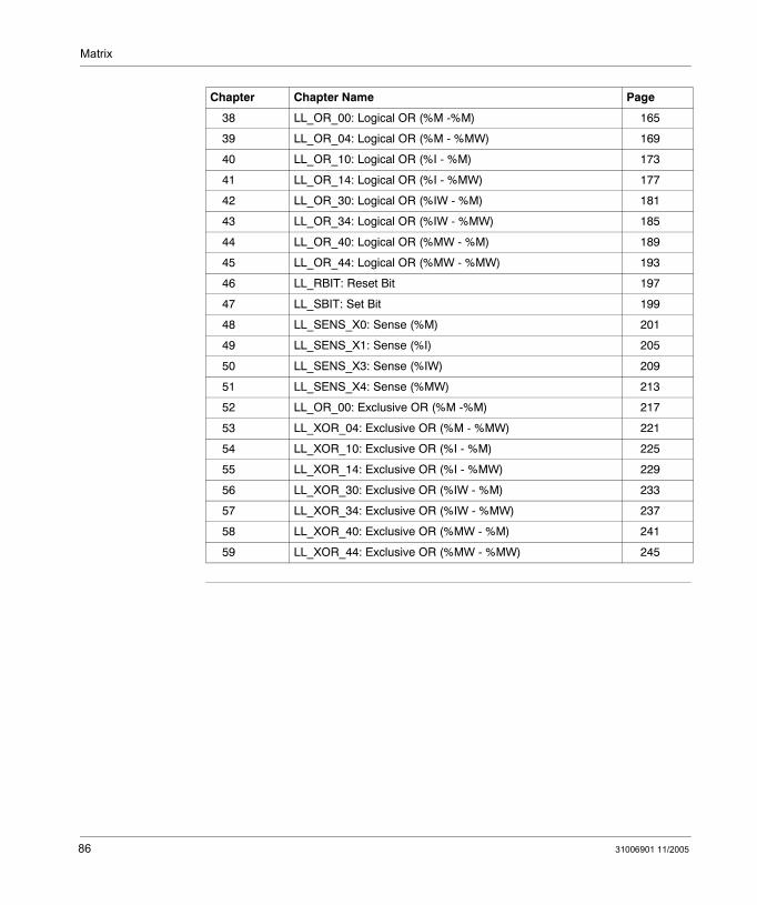
Matrix
38 LL_OR_00: Logical OR (%M -%M) 165
39 LL_OR_04: Logical OR (%M - %MW) 169
40 LL_OR_10: Logical OR (%I - %M) 173
41 LL_OR_14: Logical OR (%I - %MW) 177
42 LL_OR_30: Logical OR (%IW - %M) 181
43 LL_OR_34: Logical OR (%IW - %MW) 185
44 LL_OR_40: Logical OR (%MW - %M) 189
45 LL_OR_44: Logical OR (%MW - %MW) 193
46 LL_RBIT: Reset Bit 197
47 LL_SBIT: Set Bit 199
48 LL_SENS_X0: Sense (%M) 201
49 LL_SENS_X1: Sense (%I) 205
50 LL_SENS_X3: Sense (%IW) 209
51 LL_SENS_X4: Sense (%MW) 213
52 LL_OR_00: Exclusive OR (%M -%M) 217
53 LL_XOR_04: Exclusive OR (%M - %MW) 221
54 LL_XOR_10: Exclusive OR (%I - %M) 225
55 LL_XOR_14: Exclusive OR (%I - %MW) 229
56 LL_XOR_30: Exclusive OR (%IW - %M) 233
57 LL_XOR_34: Exclusive OR (%IW - %MW) 237
58 LL_XOR_40: Exclusive OR (%MW - %M) 241
59 LL_XOR_44: Exclusive OR (%MW - %MW) 245
Chapter Chapter Name Page
86 31006901 11/2005
31006901 11/2005
17
LL_AND_00: Logical AND (%M -%M)Description
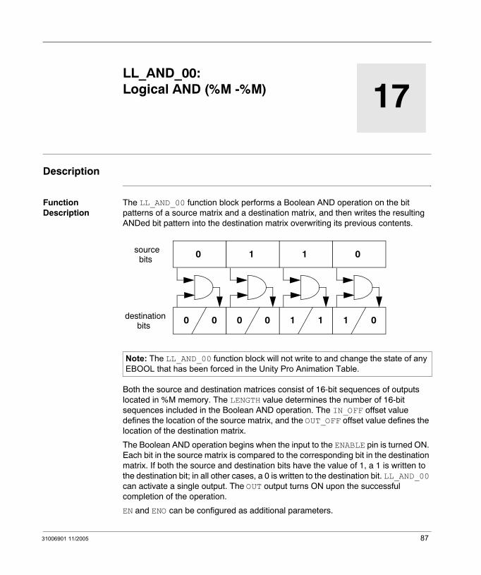
Function Description
The LL_AND_00 function block performs a Boolean AND operation on the bit patterns of a source matrix and a destination matrix, and then writes the resulting ANDed bit pattern into the destination matrix overwriting its previous contents.
Both the source and destination matrices consist of 16-bit sequences of outputs located in %M memory. The LENGTH value determines the number of 16-bit sequences included in the Boolean AND operation. The IN_OFF offset value defines the location of the source matrix, and the OUT_OFF offset value defines the location of the destination matrix.
The Boolean AND operation begins when the input to the ENABLE pin is turned ON. Each bit in the source matrix is compared to the corresponding bit in the destination matrix. If both the source and destination bits have the value of 1, a 1 is written to the destination bit; in all other cases, a 0 is written to the destination bit. LL_AND_00 can activate a single output. The OUT output turns ON upon the successful completion of the operation.
EN and ENO can be configured as additional parameters.
Note: The LL_AND_00 function block will not write to and change the state of any EBOOL that has been forced in the Unity Pro Animation Table.
0
0 0
1
0 0
sourcebits
destinationbits
1
1 1
0
1 0
87
LL_AND_00
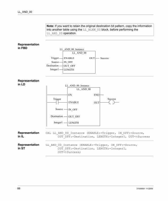
Representation in FBD
Representation in LD
Representation in IL
CAL LL_AND_00_Instance (ENABLE:=Trigger, IN_OFF:=Source, OUT_OFF:=Destination, LENGTH:=Integer1, OUT=>Success
Representation in ST
LL_AND_00_Instance (ENABLE:=Trigger, IN_OFF:=Source, OUT_OFF:=Destination, LENGTH:=Integer1, OUT=>Success;
Note: If you want to retain the original destination bit pattern, copy the information into another table using the LL_BLKM_00 block, before performing the LL_AND_00 operation.
LL_AND_00
TriggerSource
LL_AND_00_Instance
OUTENABLEIN_OFFOUT_OFFLENGTH
DestinationInteger1
Success
Trigger
Source
ENOENSuccess
LL_AND_00LL_AND_00_Instance
OUTENABLE
IN_OFF
OUT_OFF
LENGTH
Destination
Integer1
88 31006901 11/2005
LL_AND_00
Parameters
Input parameter
Data type 984LL equivalent
Meaning
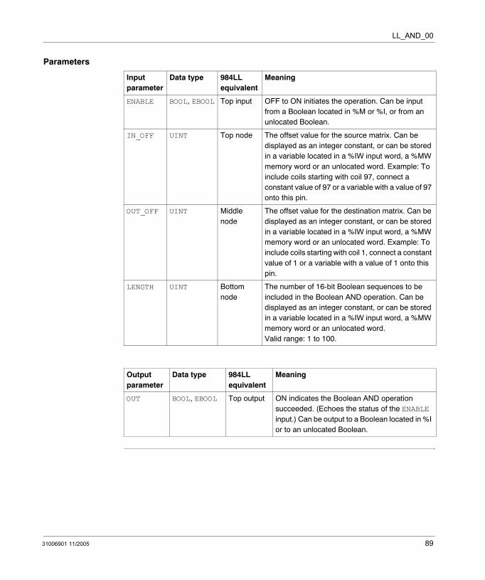
ENABLE BOOL, EBOOL Top input OFF to ON initiates the operation. Can be input from a Boolean located in %M or %I, or from an unlocated Boolean.
IN_OFF UINT Top node The offset value for the source matrix. Can be displayed as an integer constant, or can be stored in a variable located in a %IW input word, a %MW memory word or an unlocated word. Example: To include coils starting with coil 97, connect a constant value of 97 or a variable with a value of 97 onto this pin.
OUT_OFF UINT Middle node
The offset value for the destination matrix. Can be displayed as an integer constant, or can be stored in a variable located in a %IW input word, a %MW memory word or an unlocated word. Example: To include coils starting with coil 1, connect a constant value of 1 or a variable with a value of 1 onto this pin.
LENGTH UINT Bottom node
The number of 16-bit Boolean sequences to be included in the Boolean AND operation. Can be displayed as an integer constant, or can be stored in a variable located in a %IW input word, a %MW memory word or an unlocated word. Valid range: 1 to 100.
Output parameter
Data type 984LL equivalent
Meaning
OUT BOOL, EBOOL Top output ON indicates the Boolean AND operation succeeded. (Echoes the status of the ENABLE input.) Can be output to a Boolean located in %I or to an unlocated Boolean.
31006901 11/2005 89

LL_AND_00
90 31006901 11/2005
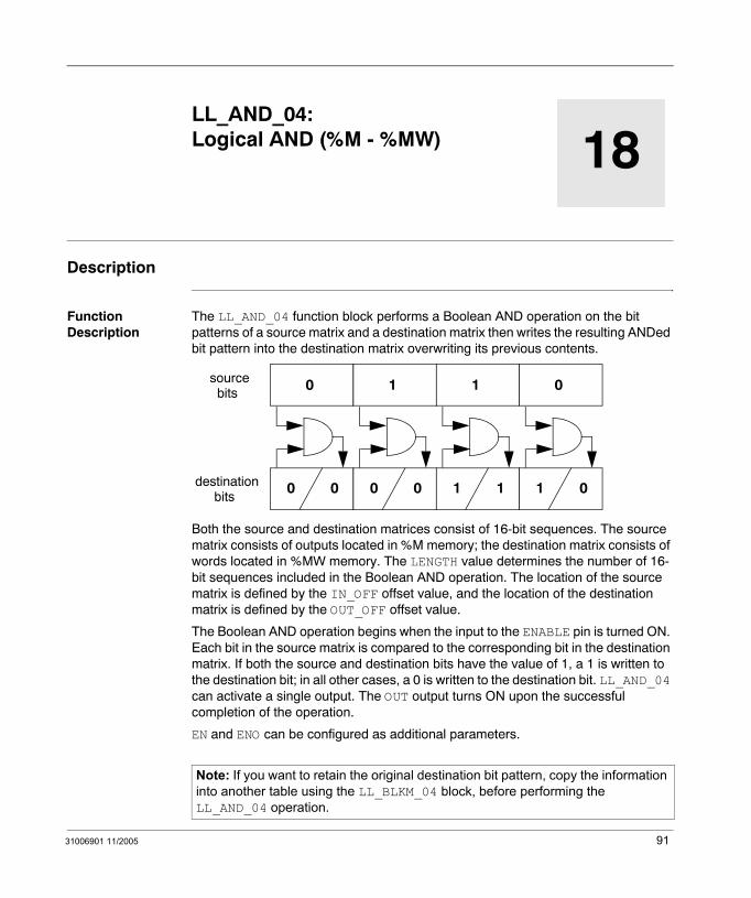
31006901 11/2005
18
LL_AND_04: Logical AND (%M - %MW)Description
Function Description
The LL_AND_04 function block performs a Boolean AND operation on the bit patterns of a source matrix and a destination matrix then writes the resulting ANDed bit pattern into the destination matrix overwriting its previous contents.
Both the source and destination matrices consist of 16-bit sequences. The source matrix consists of outputs located in %M memory; the destination matrix consists of words located in %MW memory. The LENGTH value determines the number of 16-bit sequences included in the Boolean AND operation. The location of the source matrix is defined by the IN_OFF offset value, and the location of the destination matrix is defined by the OUT_OFF offset value.
The Boolean AND operation begins when the input to the ENABLE pin is turned ON. Each bit in the source matrix is compared to the corresponding bit in the destination matrix. If both the source and destination bits have the value of 1, a 1 is written to the destination bit; in all other cases, a 0 is written to the destination bit. LL_AND_04 can activate a single output. The OUT output turns ON upon the successful completion of the operation.
EN and ENO can be configured as additional parameters.
Note: If you want to retain the original destination bit pattern, copy the information into another table using the LL_BLKM_04 block, before performing the LL_AND_04 operation.
0
0 0
1
0 0
sourcebits
destinationbits
1
1 1
0
1 0
91

LL_AND_04
Representation in FBD
Representation in LD
Representation in IL
CAL LL_AND_04_Instance (ENABLE:=Trigger, IN_OFF:=Source, OUT_OFF:=Destination, LENGTH:=Integer1, OUT=>Success
Representation in ST
LL_AND_04_Instance (ENABLE:=Trigger, IN_OFF:=Source, OUT_OFF:=Destination, LENGTH:=Integer1, OUT=>Success;
LL_AND_04
TriggerSource
LL_AND_04_Instance
OUTENABLEIN_OFFOUT_OFFLENGTH
DestinationInteger1
Success
Trigger
Source
ENOENSuccess
LL_AND_04LL_AND_04_Instance
OUTENABLE
IN_OFF
OUT_OFF
LENGTH
Destination
Integer1
92 31006901 11/2005

LL_AND_04
Parameters
Input parameter
Data type 984LL equivalent
Meaning
ENABLE BOOL, EBOOL Top input OFF to ON initiates the operation. Can be input from a Boolean located in %M or %I, or from an unlocated Boolean.
IN_OFF UINT Top node The offset value for the source matrix. Can be displayed as an integer constant, or can be stored in a variable located in a %IW input word, a %MW memory word or an unlocated word. Example: To include coils starting with coil 97, connect a constant value of 97 or a variable with a value of 97 onto this pin.
OUT_OFF UINT Middle node The offset value for the destination matrix. Can be displayed as an integer constant, or can be stored in a variable located in a %IW input word, a %MW memory word or an unlocated word. Example: To include words starting with word 1, connect a constant value of 1 or a variable with a value of 1 onto this pin.
LENGTH UINT Top input The number of 16-bit Boolean sequences to be included in the Boolean AND operation. Can be displayed as an integer constant, or can be stored in a variable located in a %IW input word, a %MW memory word or an unlocated word. Valid range: 1 to 100.
Output parameter
Data type 984LL equivalent
Meaning
OUT BOOL, EBOOL Top output ON indicates the Boolean AND operation succeeded. (Echoes the status of the ENABLE input.) Can be output to a Boolean located in %I or to an unlocated Boolean.
31006901 11/2005 93

LL_AND_04
94 31006901 11/2005

31006901 11/2005
19
LL_AND_10: Logical AND (%I - %M)Description
Function Description
The LL_AND_10 function block performs a Boolean AND operation on the bit patterns of a source matrix and a destination matrix, then writes the resulting ANDed bit pattern into the destination matrix overwriting its previous contents.
Both the source and destination matrices consist of 16-bit sequences. The source matrix consists of %I inputs; the destination matrix consists of outputs located in %M memory. The LENGTH value determines the number of 16-bit sequences included in the Boolean AND operation. The location of the source matrix is defined by the IN_OFF offset value, and the location of the destination matrix is defined by the OUT_OFF offset value.
The Boolean AND operation begins when the input to the ENABLE pin is turned ON. Each bit in the source matrix is compared to the corresponding bit in the destination matrix. If both the source and destination bits have the value of 1, a 1 is written to the destination bit; in all other cases, a 0 is written to the destination bit. LL_AND_10 can activate a single output. The OUT output turns ON upon the successful completion of the operation.
EN and ENO can be configured as additional parameters.
Note: The LL_AND_10 function block will not write to and change the state of any EBOOL that has been forced in the Unity Pro Animation Table.
0
0 0
1
0 0
sourcebits
destinationbits
1
1 1
0
1 0
95
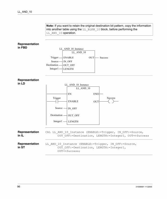
LL_AND_10
Representation in FBD
Representation in LD
Representation in IL
CAL LL_AND_10_Instance (ENABLE:=Trigger, IN_OFF:=Source, OUT_OFF:=Destination, LENGTH:=Integer1, OUT=>Success
Representation in ST
LL_AND_10_Instance (ENABLE:=Trigger, IN_OFF:=Source, OUT_OFF:=Destination, LENGTH:=Integer1, OUT=>Success;
Note: If you want to retain the original destination bit pattern, copy the information into another table using the LL_BLKM_10 block, before performing the LL_AND_10 operation.
LL_AND_10
TriggerSource
LL_AND_10_Instance
OUTENABLEIN_OFFOUT_OFFLENGTH
DestinationInteger1
Success
Trigger
Source
ENOENSuccess
LL_AND_10LL_AND_10_Instance
OUTENABLE
IN_OFF
OUT_OFF
LENGTH
Destination
Integer1
96 31006901 11/2005

LL_AND_10
Parameters
Input parameter
Data type 984LL equivalent
Meaning
ENABLE BOOL, EBOOL Top input OFF to ON initiates the operation. Can be input from a Boolean located in %I or %M, or from an unlocated Boolean.
IN_OFF UINT Top node The offset value for the source matrix. Can be displayed as an integer constant, or can be stored in a variable located in a %IW input word, a %MW memory word or an unlocated word. Example: To include coils starting with coil 97, connect a constant value of 97 or a variable with a value of 97 onto this pin.
OUT_OFF UINT Middle node The offset value for the destination matrix. Can be displayed as an integer constant, or can be stored in a variable located in a %IW input word, a %MW memory word or an unlocated word. Example: To include coils starting with coil 1, connect a constant value of 1 or a variable with a value of 1 onto this pin.
LENGTH UINT Bottom node The number of 16-bit Boolean sequences to be included in the Boolean AND operation. Can be displayed as an integer constant, or can be stored in a variable located in a %IW input word, a %MW memory word or an unlocated word. Valid range: 1 to 100.
Output parameter
Data type 984LL equivalent
Meaning
OUT BOOL, EBOOL Top output ON indicates the Boolean AND operation succeeded. (Echoes the status of the ENABLE input.) Can be output to a Boolean located in %I or to an unlocated Boolean.
31006901 11/2005 97

LL_AND_10
98 31006901 11/2005
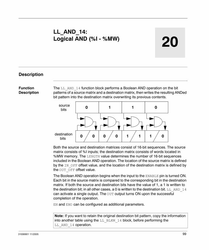
31006901 11/2005
20
LL_AND_14: Logical AND (%I - %MW)Description
Function Description
The LL_AND_14 function block performs a Boolean AND operation on the bit patterns of a source matrix and a destination matrix, then writes the resulting ANDed bit pattern into the destination matrix overwriting its previous contents.
Both the source and destination matrices consist of 16-bit sequences. The source matrix consists of %I inputs; the destination matrix consists of words located in %MW memory. The LENGTH value determines the number of 16-bit sequences included in the Boolean AND operation. The location of the source matrix is defined by the IN_OFF offset value, and the location of the destination matrix is defined by the OUT_OFF offset value.
The Boolean AND operation begins when the input to the ENABLE pin is turned ON. Each bit in the source matrix is compared to the corresponding bit in the destination matrix. If both the source and destination bits have the value of 1, a 1 is written to the destination bit; in all other cases, a 0 is written to the destination bit. LL_AND_14 can activate a single output. The OUT output turns ON upon the successful completion of the operation.
EN and ENO can be configured as additional parameters.
Note: If you want to retain the original destination bit pattern, copy the information into another table using the LL_BLKM_14 block, before performing the LL_AND_14 operation.
0
0 0
1
0 0
sourcebits
destinationbits
1
1 1
0
1 0
99
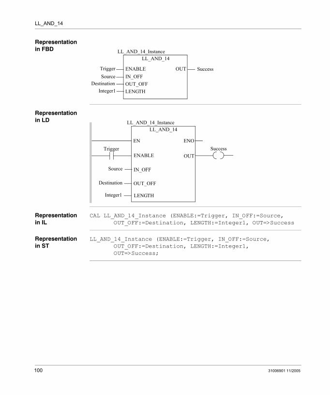
LL_AND_14
Representation in FBD
Representation in LD
Representation in IL
CAL LL_AND_14_Instance (ENABLE:=Trigger, IN_OFF:=Source, OUT_OFF:=Destination, LENGTH:=Integer1, OUT=>Success
Representation in ST
LL_AND_14_Instance (ENABLE:=Trigger, IN_OFF:=Source, OUT_OFF:=Destination, LENGTH:=Integer1, OUT=>Success;
LL_AND_14
TriggerSource
LL_AND_14_Instance
OUTENABLEIN_OFFOUT_OFFLENGTH
DestinationInteger1
Success
Trigger
Source
ENOENSuccess
LL_AND_14LL_AND_14_Instance
OUTENABLE
IN_OFF
OUT_OFF
LENGTH
Destination
Integer1
100 31006901 11/2005
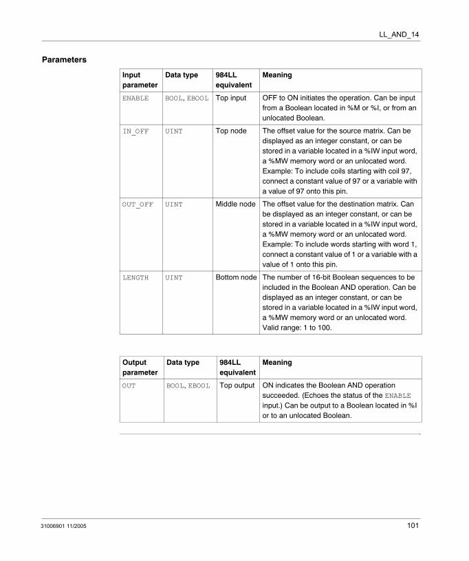
LL_AND_14
Parameters
Input parameter
Data type 984LL equivalent
Meaning
ENABLE BOOL, EBOOL Top input OFF to ON initiates the operation. Can be input from a Boolean located in %M or %I, or from an unlocated Boolean.
IN_OFF UINT Top node The offset value for the source matrix. Can be displayed as an integer constant, or can be stored in a variable located in a %IW input word, a %MW memory word or an unlocated word. Example: To include coils starting with coil 97, connect a constant value of 97 or a variable with a value of 97 onto this pin.
OUT_OFF UINT Middle node The offset value for the destination matrix. Can be displayed as an integer constant, or can be stored in a variable located in a %IW input word, a %MW memory word or an unlocated word. Example: To include words starting with word 1, connect a constant value of 1 or a variable with a value of 1 onto this pin.
LENGTH UINT Bottom node The number of 16-bit Boolean sequences to be included in the Boolean AND operation. Can be displayed as an integer constant, or can be stored in a variable located in a %IW input word, a %MW memory word or an unlocated word. Valid range: 1 to 100.
Output parameter
Data type 984LL equivalent
Meaning
OUT BOOL, EBOOL Top output ON indicates the Boolean AND operation succeeded. (Echoes the status of the ENABLE input.) Can be output to a Boolean located in %I or to an unlocated Boolean.
31006901 11/2005 101

LL_AND_14
102 31006901 11/2005

31006901 11/2005
21
LL_AND_30: Logical AND (%IW - %M)Description
Function Description
The LL_AND_30 function block performs a Boolean AND operation on the bit patterns of a source matrix and a destination matrix, then writes the resulting ANDed bit pattern into the destination matrix overwriting its previous contents.
Both the source and destination matrices consist of 16-bit sequences. The source matrix consists of %IW input words; the destination matrix consists of outputs located in %M memory. The LENGTH value determines the number of 16-bit sequences included in the Boolean AND operation. The location of the source matrix is defined by the IN_OFF offset value, and the location of the destination matrix is defined by the OUT_OFF offset value.
The Boolean AND operation begins when the input to the ENABLE pin is turned ON. Each bit in the source matrix is compared to the corresponding bit in the destination matrix. If both the source and destination bits have the value of 1, a 1 is written to the destination bit; in all other cases, a 0 is written to the destination bit. LL_AND_30 can activate a single output. The OUT output turns ON upon the successful completion of the operation.
EN and ENO can be configured as additional parameters.
Note: The LL_AND_30 function block will not write to and change the state of any EBOOL that has been forced in the Unity Pro Animation Table.
0
0 0
1
0 0
sourcebits
destinationbits
1
1 1
0
1 0
103

LL_AND_30
Representation in FBD
Representation in LD
Representation in IL
CAL LL_AND_30_Instance (ENABLE:=Trigger, IN_OFF:=Source, OUT_OFF:=Destination, LENGTH:=Integer1, OUT=>Success
Representation in ST
LL_AND_30_Instance (ENABLE:=Trigger, IN_OFF:=Source, OUT_OFF:=Destination, LENGTH:=Integer1, OUT=>Success;
Note: If you want to retain the original destination bit pattern, copy the information into another table using the LL_BLKM_30 block, before performing the LL_AND_30 operation.
LL_AND_30
TriggerSource
LL_AND_30_Instance
OUTENABLEIN_OFFOUT_OFFLENGTH
DestinationInteger1
Success
Trigger
Source
ENOENSuccess
LL_AND_30LL_AND_30_Instance
OUTENABLE
IN_OFF
OUT_OFF
LENGTH
Destination
Integer1
104 31006901 11/2005

LL_AND_30
Parameters
Input parameter
Data type 984LL equivalent
Meaning
ENABLE BOOL, EBOOL Top input OFF to ON initiates the operation. Can be input from a Boolean located in %I or %M, or from an unlocated Boolean.
IN_OFF UINT Top node The offset value for the source matrix. Can be displayed as an integer constant, or can be stored in a variable located in a $IW input word, a %MW memory word or an unlocated word. Example: To include words starting with word 97, connect a constant value of 97 or a variable with a value of 97 onto this pin.
OUT_OFF UINT Middle node The offset value for the destination matrix. Can be displayed as an integer constant, or can be stored in a variable located in a %IW input word, a %MW memory word or an unlocated word. Example: To include coils starting with coil 1, connect a constant value of 1 or a variable with a value of 1 onto this pin.
LENGTH UINT Bottom node The number of 16-bit Boolean sequences to be included in the Boolean AND operation. Can be displayed as an integer constant, or can be stored in a variable located in a %IW input word, a %MW memory word or an unlocated word. Valid range: 1 to 100.
Output parameter
Data type Meaning Meaning
OUT BOOL, EBOOL Top output ON indicates the Boolean AND operation succeeded. (Echoes the status of the ENABLE input.) Can be output to a Boolean located in %I or to an unlocated Boolean.
31006901 11/2005 105

LL_AND_30
106 31006901 11/2005

31006901 11/2005
22
LL_AND_34: Logical AND (%IW - %MW)Description
Function Description
The LL_AND_34 function block performs a Boolean AND operation on the bit patterns of a source matrix and a destination matrix, then writes the resulting ANDed bit pattern into the destination matrix overwriting its previous contents.
Both the source and destination matrices consist of 16-bit sequences. The source matrix consists of %IW input words; the destination matrix consists of located %MW memory words. The LENGTH value determines the number of 16-bit sequences included in the Boolean AND operation. The location of the source matrix is defined by the IN_OFF offset value, and the location of the destination matrix is defined by the OUT_OFF offset value.
The Boolean AND operation begins when the input to the ENABLE pin is turned ON. Each bit in the source matrix is compared to the corresponding bit in the destination matrix. If both the source and destination bits have the value of 1, a 1 is written to the destination bit; in all other cases, a 0 is written to the destination bit. LL_AND_34 can activate a single output. The OUT output turns ON upon the successful completion of the operation.
EN and ENO can be configured as additional parameters.
Note: If you want to retain the original destination bit pattern, copy the information into another table using the LL_BLKM_34 block, before performing the LL_AND_34 operation.
0
0 0
1
0 0
sourcebits
destinationbits
1
1 1
0
1 0
107

LL_AND_34
Representation in FBD
Representation in LD
Representation in IL
CAL LL_AND_34_Instance (ENABLE:=Trigger, IN_OFF:=Source, OUT_OFF:=Destination, LENGTH:=Integer1, OUT=>Success
Representation in ST
LL_AND_34_Instance (ENABLE:=Trigger, IN_OFF:=Source, OUT_OFF:=Destination, LENGTH:=Integer1, OUT=>Success;
LL_AND_34
TriggerSource
LL_AND_34_Instance
OUTENABLEIN_OFFOUT_OFFLENGTH
DestinationInteger1
Success
Trigger
Source
ENOENSuccess
LL_AND_34LL_AND_34_Instance
OUTENABLE
IN_OFF
OUT_OFF
LENGTH
Destination
Integer1
108 31006901 11/2005

LL_AND_34
Parameters
Input parameter
Data type 984LL equivalent
Meaning
ENABLE BOOL, EBOOL Top input OFF to ON initiates the operation. Can be input from a Boolean located in %M or %I, or from an unlocated Boolean.
IN_OFF UINT Top node The offset value for the source matrix. Can be displayed as an integer constant, or can be stored in a variable located in a %IW input word, a %MW memory word or an unlocated word. Example: To include words starting with word 97, connect a constant value of 97 or a variable with a value of 97 onto this pin.
OUT_OFF UINT Middle node The offset value for the destination matrix. Can be displayed as an integer constant, or can be stored in a variable located in a %IW input word, a %MW memory word or an unlocated word. Example: To include words starting with word 1, connect a constant value of 1 or a variable with a value of 1 onto this pin.
LENGTH UINT Bottom node The number of 16-bit Boolean sequences to be included in the Boolean AND operation. Can be displayed as an integer constant, or can be stored in a variable located in a %IW input word, a %MW memory word or an unlocated word. Valid range: 1 to 100.
Output parameter
Data type 984LL equivalent
Meaning
OUT BOOL, EBOOL Top output ON indicates the Boolean AND operation succeeded. (Echoes the status of the ENABLE input.) Can be output to a Boolean located in %I or to an unlocated Boolean.
31006901 11/2005 109

LL_AND_34
110 31006901 11/2005
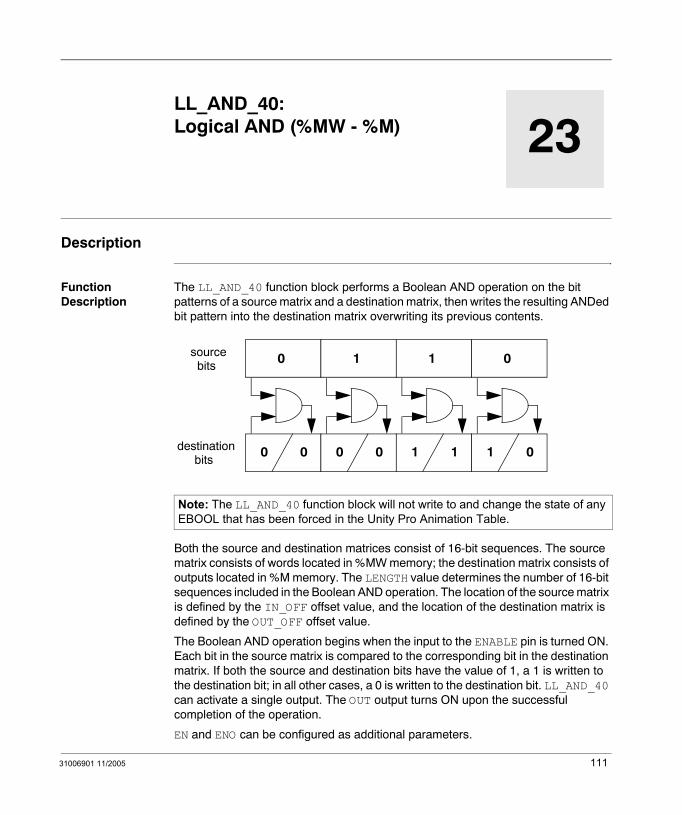
31006901 11/2005
23
LL_AND_40: Logical AND (%MW - %M)Description
Function Description
The LL_AND_40 function block performs a Boolean AND operation on the bit patterns of a source matrix and a destination matrix, then writes the resulting ANDed bit pattern into the destination matrix overwriting its previous contents.
Both the source and destination matrices consist of 16-bit sequences. The source matrix consists of words located in %MW memory; the destination matrix consists of outputs located in %M memory. The LENGTH value determines the number of 16-bit sequences included in the Boolean AND operation. The location of the source matrix is defined by the IN_OFF offset value, and the location of the destination matrix is defined by the OUT_OFF offset value.
The Boolean AND operation begins when the input to the ENABLE pin is turned ON. Each bit in the source matrix is compared to the corresponding bit in the destination matrix. If both the source and destination bits have the value of 1, a 1 is written to the destination bit; in all other cases, a 0 is written to the destination bit. LL_AND_40 can activate a single output. The OUT output turns ON upon the successful completion of the operation.
EN and ENO can be configured as additional parameters.
Note: The LL_AND_40 function block will not write to and change the state of any EBOOL that has been forced in the Unity Pro Animation Table.
0
0 0
1
0 0
sourcebits
destinationbits
1
1 1
0
1 0
111
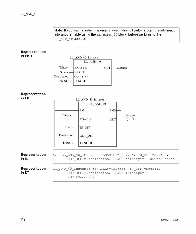
LL_AND_40
Representation in FBD
Representation in LD
Representation in IL
CAL LL_AND_40_Instance (ENABLE:=Trigger, IN_OFF:=Source, OUT_OFF:=Destination, LENGTH:=Integer1, OUT=>Success
Representation in ST
LL_AND_40_Instance (ENABLE:=Trigger, IN_OFF:=Source, OUT_OFF:=Destination, LENGTH:=Integer1, OUT=>Success;
Note: If you want to retain the original destination bit pattern, copy the information into another table using the LL_BLKM_40 block, before performing the LL_AND_40 operation.
LL_AND_40
TriggerSource
LL_AND_40_Instance
OUTENABLEIN_OFFOUT_OFFLENGTH
DestinationInteger1
Success
Trigger
Source
ENOENSuccess
LL_AND_40LL_AND_40_Instance
OUTENABLE
IN_OFF
OUT_OFF
LENGTH
Destination
Integer1
112 31006901 11/2005
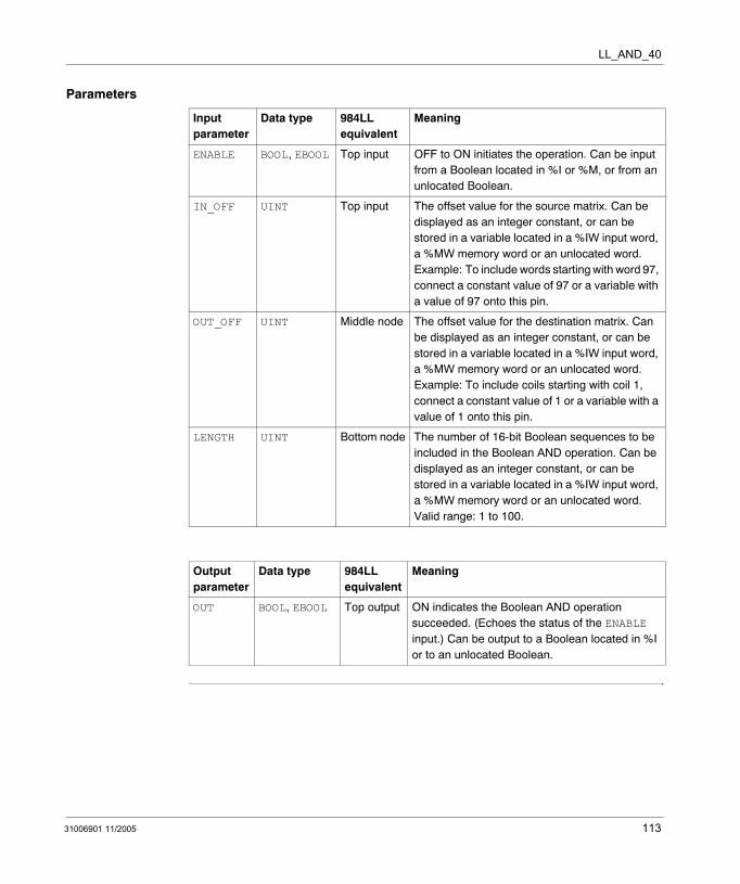
LL_AND_40
Parameters
Input parameter
Data type 984LL equivalent
Meaning
ENABLE BOOL, EBOOL Top input OFF to ON initiates the operation. Can be input from a Boolean located in %I or %M, or from an unlocated Boolean.
IN_OFF UINT Top input The offset value for the source matrix. Can be displayed as an integer constant, or can be stored in a variable located in a %IW input word, a %MW memory word or an unlocated word. Example: To include words starting with word 97, connect a constant value of 97 or a variable with a value of 97 onto this pin.
OUT_OFF UINT Middle node The offset value for the destination matrix. Can be displayed as an integer constant, or can be stored in a variable located in a %IW input word, a %MW memory word or an unlocated word. Example: To include coils starting with coil 1, connect a constant value of 1 or a variable with a value of 1 onto this pin.
LENGTH UINT Bottom node The number of 16-bit Boolean sequences to be included in the Boolean AND operation. Can be displayed as an integer constant, or can be stored in a variable located in a %IW input word, a %MW memory word or an unlocated word. Valid range: 1 to 100.
Output parameter
Data type 984LL equivalent
Meaning
OUT BOOL, EBOOL Top output ON indicates the Boolean AND operation succeeded. (Echoes the status of the ENABLE input.) Can be output to a Boolean located in %I or to an unlocated Boolean.
31006901 11/2005 113

LL_AND_40
114 31006901 11/2005
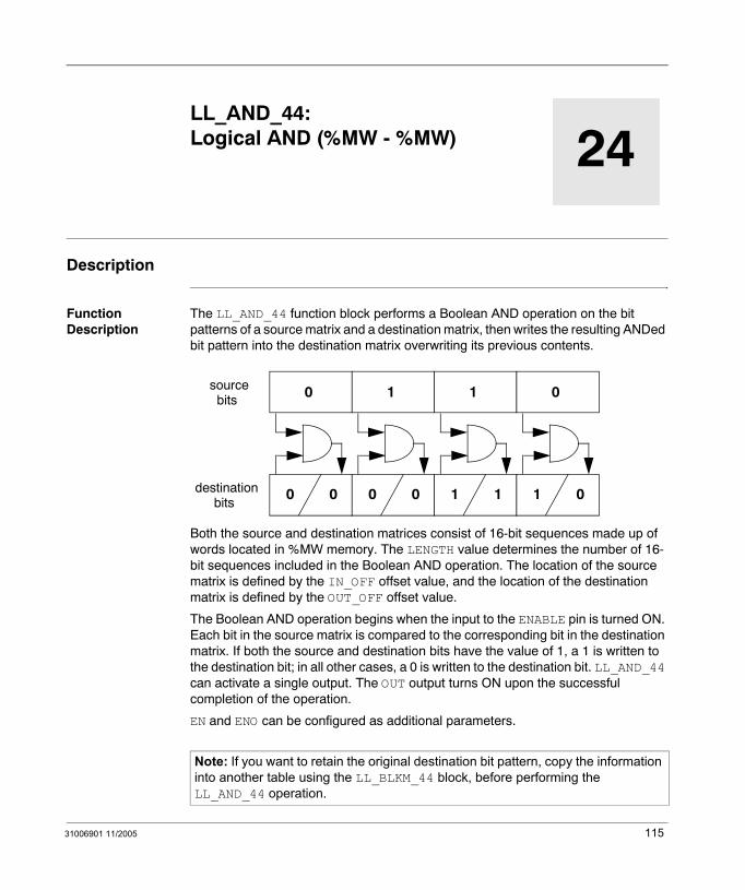
31006901 11/2005
24
LL_AND_44: Logical AND (%MW - %MW)Description
Function Description
The LL_AND_44 function block performs a Boolean AND operation on the bit patterns of a source matrix and a destination matrix, then writes the resulting ANDed bit pattern into the destination matrix overwriting its previous contents.
Both the source and destination matrices consist of 16-bit sequences made up of words located in %MW memory. The LENGTH value determines the number of 16-bit sequences included in the Boolean AND operation. The location of the source matrix is defined by the IN_OFF offset value, and the location of the destination matrix is defined by the OUT_OFF offset value.
The Boolean AND operation begins when the input to the ENABLE pin is turned ON. Each bit in the source matrix is compared to the corresponding bit in the destination matrix. If both the source and destination bits have the value of 1, a 1 is written to the destination bit; in all other cases, a 0 is written to the destination bit. LL_AND_44 can activate a single output. The OUT output turns ON upon the successful completion of the operation.
EN and ENO can be configured as additional parameters.
Note: If you want to retain the original destination bit pattern, copy the information into another table using the LL_BLKM_44 block, before performing the LL_AND_44 operation.
0
0 0
1
0 0
sourcebits
destinationbits
1
1 1
0
1 0
115
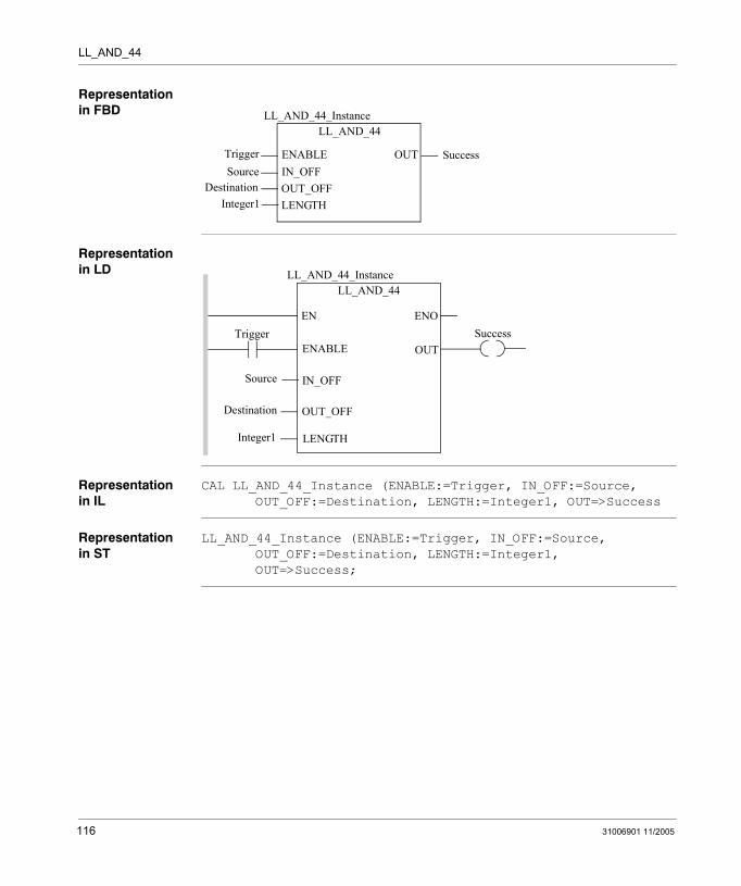
LL_AND_44
Representation in FBD
Representation in LD
Representation in IL
CAL LL_AND_44_Instance (ENABLE:=Trigger, IN_OFF:=Source, OUT_OFF:=Destination, LENGTH:=Integer1, OUT=>Success
Representation in ST
LL_AND_44_Instance (ENABLE:=Trigger, IN_OFF:=Source, OUT_OFF:=Destination, LENGTH:=Integer1, OUT=>Success;
LL_AND_44
TriggerSource
LL_AND_44_Instance
OUTENABLEIN_OFFOUT_OFFLENGTH
DestinationInteger1
Success
Trigger
Source
ENOENSuccess
LL_AND_44LL_AND_44_Instance
OUTENABLE
IN_OFF
OUT_OFF
LENGTH
Destination
Integer1
116 31006901 11/2005
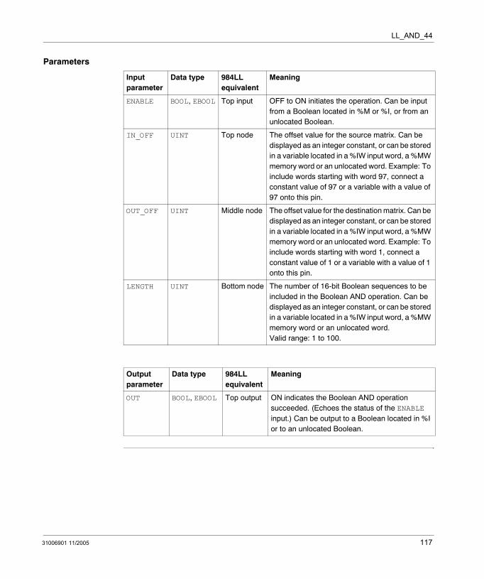
LL_AND_44
Parameters
Input parameter
Data type 984LL equivalent
Meaning
ENABLE BOOL, EBOOL Top input OFF to ON initiates the operation. Can be input from a Boolean located in %M or %I, or from an unlocated Boolean.
IN_OFF UINT Top node The offset value for the source matrix. Can be displayed as an integer constant, or can be stored in a variable located in a %IW input word, a %MW memory word or an unlocated word. Example: To include words starting with word 97, connect a constant value of 97 or a variable with a value of 97 onto this pin.
OUT_OFF UINT Middle node The offset value for the destination matrix. Can be displayed as an integer constant, or can be stored in a variable located in a %IW input word, a %MW memory word or an unlocated word. Example: To include words starting with word 1, connect a constant value of 1 or a variable with a value of 1 onto this pin.
LENGTH UINT Bottom node The number of 16-bit Boolean sequences to be included in the Boolean AND operation. Can be displayed as an integer constant, or can be stored in a variable located in a %IW input word, a %MW memory word or an unlocated word. Valid range: 1 to 100.
Output parameter
Data type 984LL equivalent
Meaning
OUT BOOL, EBOOL Top output ON indicates the Boolean AND operation succeeded. (Echoes the status of the ENABLE input.) Can be output to a Boolean located in %I or to an unlocated Boolean.
31006901 11/2005 117

LL_AND_44
118 31006901 11/2005
31006901 11/2005
25
LL_BROT_00: Bit Rotate (%M -%M)Description
Function Description
The LL_BROT_00 function block shifts or rotates the bit pattern in a source matrix, then writes the changed bit pattern into a destination matrix. The bit pattern shifts or rotates left or right by 1 position per scan, overwriting the destination matrix’s previous contents.
Both the source and destination matrices consist of 16-bit sequences of outputs located in %M memory. The LENGTH value determines the number of 16-bit sequences included in the shift or rotate operation. The location of the source matrix is defined by the IN_OFF offset value, and the location of the destination matrix is defined by the OUT_OFF offset value.
The operation begins when the input to the ENABLE pin is turned ON. If the DIR pin is turned ON, the source matrix will move left 1 position; if the DIR pin is turned OFF, the source matrix will move right 1 position.
If the SHFT_ROT bit is ON, the selected matrix will rotate and the exiting bit will wrap around to the opposite side of the source matrix. If the SHFT_ROT bit is OFF, the selected matrix will shift, the exiting bit will be dropped, and a 0 will fill-in on the opposite side of the source matrix.
The OUT output turns ON upon the successful completion of the operation. The EXIT_BIT output holds the value of the exiting bit.
EN and ENO can be configured as additional parameters.
Note: The LL_BROT_00 function block will not write to and change the state of any EBOOL that has been forced in the Unity Pro Animation Table.
119

LL_BROT_00
Representation in FBD
Representation in LD
Representation in IL
CAL LL_BROT_00_Instance (ENABLE:=Trigger, DIR:=LeftRight, SHIFT_ROT:=FuncSelect, IN_OFF:=Source, OUT_OFF:=Destination, LENGTH:=Integer1, OUT=>Success, EXIT_BIT=>Value)
Representation in ST
LL_BROT_00_Instance (ENABLE:=Trigger, DIR:=LeftRight, SHIFT_ROT:=FuncSelect, IN_OFF:=Source, OUT_OFF:=Destination, LENGTH:=Integer1, OUT=>Success, EXIT_BIT=>Value);
LL_BROT_00
TriggerLeftRight
LL_BROT_00_Instance
OUTENABLEDIRSHIFT_ROTIN_OFF
FuncSelectSource
SuccessEXIT_BIT Value
OUT_OFFDestinationLENGTHInteger1
Trigger
Source
ENOENSuccess
LL_BROT_00LL_BROT_00_Instance
OUTENABLE
IN_OFF
OUT_OFF
LENGTH
Destination
Integer1
ValueEXIT_BIT
FuncSelectSHIFT_ROT
LeftRightDIR
120 31006901 11/2005
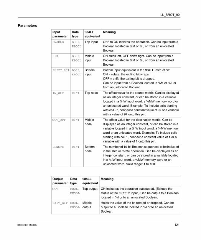
LL_BROT_00
Parameters
Input parameter
Data type
984LL equivalent
Meaning
ENABLE BOOL, EBOOL
Top input OFF to ON initiates the operation. Can be input from a Boolean located in %M or %I, or from an unlocated Boolean.
DIR BOOL, EBOOL
Middle input
ON shifts left, OFF shifts right. Can be input from a Boolean located in %M or %I, or from an unlocated Boolean.
SHIFT_ROT BOOL, EBOOL
Bottom input
Bottom input equivalent in the 984LL instruction: ON = rotate; the exiting bit wraps. OFF = shift; the exiting bit is dropped.Can be input from a Boolean located in %M or %I, or from an unlocated Boolean.
IN_OFF UINT Top node The offset value for the source matrix. Can be displayed as an integer constant, or can be stored in a variable located in a %IW input word, a %MW memory word or an unlocated word. Example: To include coils starting with coil 97, connect a constant value of 97 or a variable with a value of 97 onto this pin.
OUT_OFF UINT Middle node
The offset value for the destination matrix. Can be displayed as an integer constant, or can be stored in a variable located in a %IW input word, a %MW memory word or an unlocated word. Example: To include coils starting with coil 1, connect a constant value of 1 or a variable with a value of 1 onto this pin.
LENGTH UINT Bottom node
The number of 16-bit Boolean sequences to be included in the shift or rotate operation. Can be displayed as an integer constant, or can be stored in a variable located in a %IW input word, a %MW memory word or an unlocated word. Valid range: 1 to 100.
Output parameter
Data type
984LL equivalent
Meaning
OUT BOOL, EBOOL
Top output ON indicates the operation succeeded. (Echoes the status of the ENABLE input.) Can be output to a Boolean located in %I or to an unlocated Boolean.
EXIT_BIT BOOL, EBOOL
Middle output
Holds the value of the bit rotated or dropped. Can be output to a Boolean located in %I or to an unlocated Boolean.
31006901 11/2005 121

LL_BROT_00
122 31006901 11/2005

31006901 11/2005
26
LL_BROT_04: Bit Rotate (%M - %MW)Description
Function Description
The LL_BROT_04 function block shifts or rotates the bit pattern in a source matrix, then writes the changed bit pattern into a destination matrix. The bit pattern shifts or rotates left or right by 1 position per scan, overwriting the destination matrix’s previous contents.
Both the source and destination matrices consist of 16-bit sequences. The source matrix consists of outputs located in %M memory; the destination matrix consists of words located in %MW memory. The LENGTH value determines the number of 16-bit sequences included in the shift or rotate operation. The location of the source matrix is defined by the IN_OFF offset value, and the location of the destination matrix is defined by the OUT_OFF offset value.
The operation begins when the input to the ENABLE pin is turned ON. If the DIR pin is turned ON, the source matrix will move left 1 position; if the DIR pin is turned OFF, the source matrix will move right 1 position.
If the SHFT_ROT bit is ON, the selected matrix will rotate and the exiting bit will wrap around to the opposite side of the source matrix. If the SHFT_ROT bit is OFF, the selected matrix will shift, the exiting bit will be dropped, and a 0 will fill-in on the opposite side of the source matrix.
The OUT output turns ON upon the successful completion of the operation. The EXIT_BIT output holds the value of the exiting bit.
EN and ENO can be configured as additional parameters.
123

LL_BROT_04
Representation in FBD
Representation in LD
Representation in IL
CAL LL_BROT_04_Instance (ENABLE:=Trigger, DIR:=LeftRight, SHIFT_ROT:=FuncSelect, IN_OFF:=Source, OUT_OFF:=Destination, LENGTH:=Integer1, OUT=>Success, EXIT_BIT=>Value)
Representation in ST
LL_BROT_04_Instance (ENABLE:=Trigger, DIR:=LeftRight, SHIFT_ROT:=FuncSelect, IN_OFF:=Source, OUT_OFF:=Destination, LENGTH:=Integer1, OUT=>Success, EXIT_BIT=>Value);
LL_BROT_04
TriggerLeftRight
LL_BROT_04_Instance
OUTENABLEDIRSHIFT_ROTIN_OFF
FuncSelectSource
SuccessEXIT_BIT Value
OUT_OFFDestinationLENGTHInteger1
Trigger
Source
ENOENSuccess
LL_BROT_04LL_BROT_04_Instance
OUTENABLE
IN_OFF
OUT_OFF
LENGTH
Destination
Integer1
ValueEXIT_BIT
FuncSelectSHIFT_ROT
LeftRightDIR
124 31006901 11/2005

LL_BROT_04
Parameters
Input parameter
Data type
984LL equivalent
Meaning
ENABLE BOOL, EBOOL
Top input OFF to ON initiates the operation. Can be input from a Boolean located in %M or %I, or from an unlocated Boolean.
DIR BOOL, EBOOL
Middle input
ON shifts left, OFF shifts right. Can be input from a Boolean located in %M or %I, or from an unlocated Boolean.
SHIFT_ROT BOOL, EBOOL
Bottom input
ON = rotate; the exiting bit wraps.OFF = shift; the exiting bit is dropped.Can be input from a Boolean located in %M or %I, or from an unlocated Boolean.
IN_OFF UINT Top node The offset value for the source matrix. Can be displayed as an integer constant, or can be stored in a variable located in a %IW input word, a %MW memory word or an unlocated word. Example: To include coils starting with coil 97, connect a constant value of 97 or a variable with a value of 97 onto this pin.
OUT_OFF UINT Middle node
The offset value for the destination matrix. Can be displayed as an integer constant, or can be stored in a variable located in a %IW input word, a %MW memory word or an unlocated word. Example: To include words starting with word 1, connect a constant value of 1 or a variable with a value of 1 onto this pin.
LENGTH UINT Bottom node
The number of 16-bit Boolean sequences to be included in the shift or rotate operation. Can be displayed as an integer constant, or can be stored in a variable located in a %IW input word, a %MW memory word or an unlocated word. Valid range: 1 to 100.
Output parameter
Data type
984LL equivalent
Meaning
OUT BOOL, EBOOL
Top output ON indicates the operation succeeded. (Echoes the status of the ENABLE input.) Can be output to a Boolean located in %I or to an unlocated Boolean.
EXIT_BIT BOOL, EBOOL
Middle output
Holds the value of the bit rotated or dropped. Can be output to a Boolean located in %I or to an unlocated Boolean.
31006901 11/2005 125

LL_BROT_04
126 31006901 11/2005
31006901 11/2005
27
LL_BROT_10: Bit Rotate (%I - %M)Description
Function Description
The LL_BROT_10 function block shifts or rotates the bit pattern in a source matrix, then writes the changed bit pattern into a destination matrix. The bit pattern shifts or rotates left or right by 1 position per scan, overwriting the destination matrix’s previous contents.
Both the source and destination matrices consist of 16-bit sequences. The source matrix consists of %I inputs; the destination matrix consists of outputs located in %M memory. The LENGTH value determines the number of 16-bit sequences included in the shift or rotate operation. The location of the source matrix is defined by the IN_OFF offset value, and the location of the destination matrix is defined by the OUT_OFF offset value.
The operation begins when the input to the ENABLE pin is turned ON. If the DIR pin is turned ON, the source matrix will move left 1 position; if the DIR pin is turned OFF, the source matrix will move right 1 position.
If the SHFT_ROT bit is ON, the selected matrix will rotate and the exiting bit will wrap around to the opposite side of the source matrix. If the SHFT_ROT bit is OFF, the selected matrix will shift, the exiting bit will be dropped, and a 0 will fill-in on the opposite side of the source matrix.
The OUT output turns ON upon the successful completion of the operation. The EXIT_BIT output holds the value of the exiting bit.
EN and ENO can be configured as additional parameters.
Note: The LL_BROT_10 function block will not write to and change the state of any EBOOL that has been forced in the Unity Pro Animation Table.
127

LL_BROT_10
Representation in FBD
Representation in LD
Representation in IL
CAL LL_BROT_10_Instance (ENABLE:=Trigger, DIR:=LeftRight, SHIFT_ROT:=FuncSelect, IN_OFF:=Source, OUT_OFF:=Destination, LENGTH:=Integer1, OUT=>Success, EXIT_BIT=>Value)
Representation in ST
LL_BROT_10_Instance (ENABLE:=Trigger, DIR:=LeftRight, SHIFT_ROT:=FuncSelect, IN_OFF:=Source, OUT_OFF:=Destination, LENGTH:=Integer1, OUT=>Success, EXIT_BIT=>Value);
LL_BROT_10
TriggerLeftRight
LL_BROT_10_Instance
OUTENABLEDIRSHIFT_ROTIN_OFF
FuncSelectSource
SuccessEXIT_BIT Value
OUT_OFFDestinationLENGTHInteger1
Trigger
Source
ENOENSuccess
LL_BROT_10LL_BROT_10_Instance
OUTENABLE
IN_OFF
OUT_OFF
LENGTH
Destination
Integer1
ValueEXIT_BIT
FuncSelectSHIFT_ROT
LeftRightDIR
128 31006901 11/2005
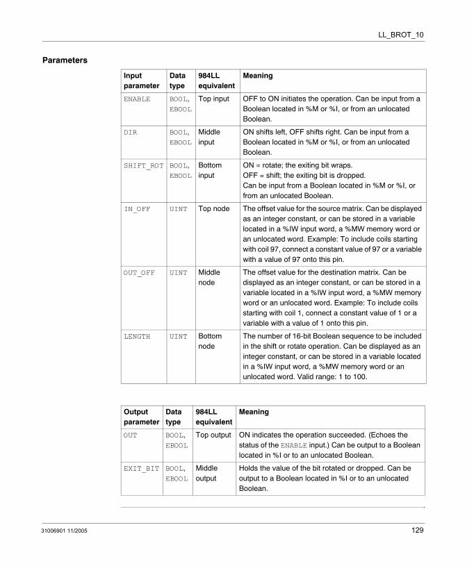
LL_BROT_10
Parameters
Input parameter
Data type
984LL equivalent
Meaning
ENABLE BOOL, EBOOL
Top input OFF to ON initiates the operation. Can be input from a Boolean located in %M or %I, or from an unlocated Boolean.
DIR BOOL, EBOOL
Middle input
ON shifts left, OFF shifts right. Can be input from a Boolean located in %M or %I, or from an unlocated Boolean.
SHIFT_ROT BOOL, EBOOL
Bottom input
ON = rotate; the exiting bit wraps. OFF = shift; the exiting bit is dropped.Can be input from a Boolean located in %M or %I, or from an unlocated Boolean.
IN_OFF UINT Top node The offset value for the source matrix. Can be displayed as an integer constant, or can be stored in a variable located in a %IW input word, a %MW memory word or an unlocated word. Example: To include coils starting with coil 97, connect a constant value of 97 or a variable with a value of 97 onto this pin.
OUT_OFF UINT Middle node
The offset value for the destination matrix. Can be displayed as an integer constant, or can be stored in a variable located in a %IW input word, a %MW memory word or an unlocated word. Example: To include coils starting with coil 1, connect a constant value of 1 or a variable with a value of 1 onto this pin.
LENGTH UINT Bottom node
The number of 16-bit Boolean sequence to be included in the shift or rotate operation. Can be displayed as an integer constant, or can be stored in a variable located in a %IW input word, a %MW memory word or an unlocated word. Valid range: 1 to 100.
Output parameter
Data type
984LL equivalent
Meaning
OUT BOOL, EBOOL
Top output ON indicates the operation succeeded. (Echoes the status of the ENABLE input.) Can be output to a Boolean located in %I or to an unlocated Boolean.
EXIT_BIT BOOL, EBOOL
Middle output
Holds the value of the bit rotated or dropped. Can be output to a Boolean located in %I or to an unlocated Boolean.
31006901 11/2005 129

LL_BROT_10
130 31006901 11/2005
31006901 11/2005
28
LL_BROT_14: Bit Rotate (%I - %MW)Description
Function Description
The LL_BROT_14 function block shifts or rotates the bit pattern in a source matrix, then writes the changed bit pattern into a destination matrix. The bit pattern shifts or rotates left or right by 1 position per scan, overwriting the destination matrix’s previous contents.
Both the source and destination matrices consist of 16-bit sequences. The source matrix consists of %I inputs; the destination matrix consists of words located in %MW memory. The LENGTH value determines the number of 16-bit sequences included in the shift or rotate operation. The location of the source matrix is defined by the IN_OFF offset value, and the location of the destination matrix is defined by the OUT_OFF offset value.
The operation begins when the input to the ENABLE pin is turned ON. If the DIR pin is turned ON, the source matrix will move left 1 position; if the DIR pin is turned OFF, the source matrix will move right 1 position.
If the SHFT_ROT bit is ON, the selected matrix will rotate and the exiting bit will wrap around to the opposite side of the source matrix. If the SHFT_ROT bit is OFF, the selected matrix will shift, the exiting bit will be dropped, and a 0 will fill-in on the opposite side of the source matrix.
The OUT output turns ON upon the successful completion of the operation. The EXIT_BIT output holds the value of the exiting bit.
EN and ENO can be configured as additional parameters.
131

LL_BROT_14
Representation in FBD
Representation in LD
Representation in IL
CAL LL_BROT_14_Instance (ENABLE:=Trigger, DIR:=LeftRight, SHIFT_ROT:=FuncSelect, IN_OFF:=Source, OUT_OFF:=Destination, LENGTH:=Integer1, OUT=>Success, EXIT_BIT=>Value)
Representation in ST
LL_BROT_14_Instance (ENABLE:=Trigger, DIR:=LeftRight, SHIFT_ROT:=FuncSelect, IN_OFF:=Source, OUT_OFF:=Destination, LENGTH:=Integer1, OUT=>Success, EXIT_BIT=>Value);
LL_BROT_14
TriggerLeftRight
LL_BROT_14_Instance
OUTENABLEDIRSHIFT_ROTIN_OFF
FuncSelectSource
SuccessEXIT_BIT Value
OUT_OFFDestinationLENGTHInteger1
Trigger
Source
ENOENSuccess
LL_BROT_14LL_BROT_14_Instance
OUTENABLE
IN_OFF
OUT_OFF
LENGTH
Destination
Integer1
ValueEXIT_BIT
FuncSelectSHIFT_ROT
LeftRightDIR
132 31006901 11/2005
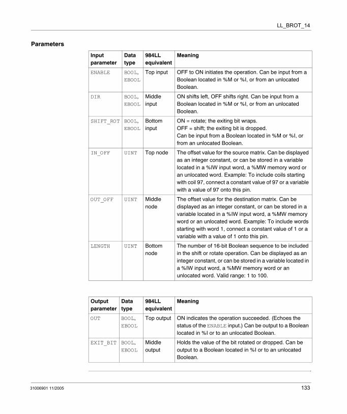
LL_BROT_14
Parameters
Input parameter
Data type
984LL equivalent
Meaning
ENABLE BOOL, EBOOL
Top input OFF to ON initiates the operation. Can be input from a Boolean located in %M or %I, or from an unlocated Boolean.
DIR BOOL, EBOOL
Middle input
ON shifts left, OFF shifts right. Can be input from a Boolean located in %M or %I, or from an unlocated Boolean.
SHIFT_ROT BOOL, EBOOL
Bottom input
ON = rotate; the exiting bit wraps. OFF = shift; the exiting bit is dropped.Can be input from a Boolean located in %M or %I, or from an unlocated Boolean.
IN_OFF UINT Top node The offset value for the source matrix. Can be displayed as an integer constant, or can be stored in a variable located in a %IW input word, a %MW memory word or an unlocated word. Example: To include coils starting with coil 97, connect a constant value of 97 or a variable with a value of 97 onto this pin.
OUT_OFF UINT Middle node
The offset value for the destination matrix. Can be displayed as an integer constant, or can be stored in a variable located in a %IW input word, a %MW memory word or an unlocated word. Example: To include words starting with word 1, connect a constant value of 1 or a variable with a value of 1 onto this pin.
LENGTH UINT Bottom node
The number of 16-bit Boolean sequence to be included in the shift or rotate operation. Can be displayed as an integer constant, or can be stored in a variable located in a %IW input word, a %MW memory word or an unlocated word. Valid range: 1 to 100.
Output parameter
Data type
984LL equivalent
Meaning
OUT BOOL, EBOOL
Top output ON indicates the operation succeeded. (Echoes the status of the ENABLE input.) Can be output to a Boolean located in %I or to an unlocated Boolean.
EXIT_BIT BOOL, EBOOL
Middle output
Holds the value of the bit rotated or dropped. Can be output to a Boolean located in %I or to an unlocated Boolean.
31006901 11/2005 133

LL_BROT_14
134 31006901 11/2005
31006901 11/2005
29
LL_BROT_30: Bit Rotate (%IW - %M)Description
Function Description
The LL_BROT_30 function block shifts or rotates the bit pattern in a source matrix, then writes the changed bit pattern into a destination matrix. The bit pattern shifts or rotates left or right by 1 position per scan, overwriting the destination matrix’s previous contents.
Both the source and destination matrices consist of 16-bit sequences. The source matrix consists of %IW input words; the destination matrix consists of outputs located in %M memory. The LENGTH value determines the number of 16-bit sequences included in the shift or rotate operation. The location of the source matrix is defined by the IN_OFF offset value, and the location of the destination matrix is defined by the OUT_OFF offset value.
The operation begins when the input to the ENABLE pin is turned ON. If the DIR pin is turned ON, the source matrix will move left 1 position; if the DIR pin is turned OFF, the source matrix will move right 1 position.
If the SHFT_ROT bit is ON, the selected matrix will rotate and the exiting bit will wrap around to the opposite side of the source matrix. If the SHFT_ROT bit is OFF, the selected matrix will shift, the exiting bit will be dropped, and a 0 will fill-in on the opposite side of the source matrix.
The OUT output turns ON upon the successful completion of the operation. The EXIT_BIT output holds the value of the exiting bit.
EN and ENO can be configured as additional parameters.
Note: The LL_BROT_30 function block will not write to and change the state of any EBOOL that has been forced in the Unity Pro Animation Table.
135
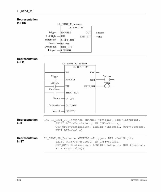
LL_BROT_30
Representation in FBD
Representation in LD
Representation in IL
CAL LL_BROT_30_Instance (ENABLE:=Trigger, DIR:=LeftRight, SHIFT_ROT:=FuncSelect, IN_OFF:=Source, OUT_OFF:=Destination, LENGTH:=Integer1, OUT=>Success, EXIT_BIT=>Value)
Representation in ST
LL_BROT_30_Instance (ENABLE:=Trigger, DIR:=LeftRight, SHIFT_ROT:=FuncSelect, IN_OFF:=Source, OUT_OFF:=Destination, LENGTH:=Integer1, OUT=>Success, EXIT_BIT=>Value);
LL_BROT_30
TriggerLeftRight
LL_BROT_30_Instance
OUTENABLEDIRSHIFT_ROTIN_OFF
FuncSelectSource
SuccessEXIT_BIT Value
OUT_OFFDestinationLENGTHInteger1
Trigger
Source
ENOENSuccess
LL_BROT_30LL_BROT_30_Instance
OUTENABLE
IN_OFF
OUT_OFF
LENGTH
Destination
Integer1
ValueEXIT_BIT
FuncSelectSHIFT_ROT
LeftRightDIR
136 31006901 11/2005

LL_BROT_30
Parameters
Input parameter
Data type
984LL equivalent
Meaning
ENABLE BOOL, EBOOL
Top input OFF to ON initiates the operation. Can be input from a Boolean located in %M or %I, or from an unlocated Boolean.
DIR BOOL, EBOOL
Middle input
ON shifts left, OFF shifts right. Can be input from a Boolean located in %M or %I, or from an unlocated Boolean.
SHIFT_ROT BOOL, EBOOL
Bottom input
ON = rotate; the exiting bit wraps. OFF = shift; the exiting bit is dropped.Can be input from a Boolean located in %M or %I, or from an unlocated Boolean.
IN_OFF UINT Top node The offset value for the source matrix. Can be displayed as an integer constant, or can be stored in a variable located in a %IW input word, a %MW memory word or an unlocated word. Example: To include words starting with word 97, connect a constant value of 97 or a variable with a value of 97 onto this pin.
OUT_OFF UINT Middle node
The offset value for the destination matrix. Can be displayed as an integer constant, or can be stored in a variable located in a %IW input word, a %MW memory word or an unlocated word. Example: To include coils starting with coil 1, connect a constant value of 1 or a variable with a value of 1 onto this pin.
LENGTH UINT Bottom node
The number of 16-bit Boolean sequences to be included in the shift or rotate operation. Can be displayed as an integer constant, or can be stored in a variable located in a %IW input word, a %MW memory word or an unlocated word. Valid range: 1 to 100.
Output parameter
Data type
984LL equivalent
Meaning
OUT BOOL, EBOOL
Top output ON indicates the operation succeeded. (Echoes the status of the ENABLE input.) Can be output to a Boolean located in %I or to an unlocated Boolean.
EXIT_BIT BOOL, EBOOL
Middle output
Holds the value of the bit rotated or dropped. Can be output to a Boolean located in %I or to an unlocated Boolean.
31006901 11/2005 137

LL_BROT_30
138 31006901 11/2005

31006901 11/2005
30
LL_BROT_34: Bit Rotate (%IW - %MW)Description
Function Description
The LL_BROT_34 function block shifts or rotates the bit pattern in a source matrix, then writes the changed bit pattern into a destination matrix. The bit pattern shifts or rotates left or right by 1 position per scan, overwriting the destination matrix’s previous contents.
Both the source and destination matrices consist of 16-bit sequences. The source matrix consists of %IW input words; the destination matrix consists of words located in %MW memory. The LENGTH value determines the number of 16-bit sequences included in the shift or rotate operation. The location of the source matrix is defined by the IN_OFF offset value, and the location of the destination matrix is defined by the OUT_OFF offset value.
The operation begins when the input to the ENABLE pin is turned ON. If the DIR pin is turned ON, the source matrix will move left 1 position; if the DIR pin is turned OFF, the source matrix will move right 1 position.
If the SHFT_ROT bit is ON, the selected matrix will rotate and the exiting bit will wrap around to the opposite side of the source matrix. If the SHFT_ROT bit is OFF, the selected matrix will shift, the exiting bit will be dropped, and a 0 will fill-in on the opposite side of the source matrix.
The OUT output turns ON upon the successful completion of the operation. The EXIT_BIT output holds the value of the exiting bit.
EN and ENO can be configured as additional parameters.
139
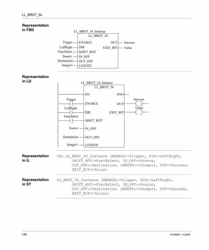
LL_BROT_34
Representation in FBD
Representation in LD
Representation in IL
CAL LL_BROT_34_Instance (ENABLE:=Trigger, DIR:=LeftRight, SHIFT_ROT:=FuncSelect, IN_OFF:=Source, OUT_OFF:=Destination, LENGTH:=Integer1, OUT=>Success, EXIT_BIT=>Value)
Representation in ST
LL_BROT_34_Instance (ENABLE:=Trigger, DIR:=LeftRight, SHIFT_ROT:=FuncSelect, IN_OFF:=Source, OUT_OFF:=Destination, LENGTH:=Integer1, OUT=>Success, EXIT_BIT=>Value);
LL_BROT_34
TriggerLeftRight
LL_BROT_34_Instance
OUTENABLEDIRSHIFT_ROTIN_OFF
FuncSelectSource
SuccessEXIT_BIT Value
OUT_OFFDestinationLENGTHInteger1
Trigger
Source
ENOENSuccess
LL_BROT_34LL_BROT_34_Instance
OUTENABLE
IN_OFF
OUT_OFF
LENGTH
Destination
Integer1
ValueEXIT_BIT
FuncSelectSHIFT_ROT
LeftRightDIR
140 31006901 11/2005
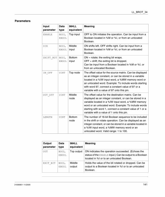
LL_BROT_34
Parameters
Input parameter
Data type
984LL equivalent
Meaning
ENABLE BOOL, EBOOL
Top input OFF to ON initiates the operation. Can be input from a Boolean located in %M or %I, or from an unlocated Boolean.
DIR BOOL, EBOOL
Middle input
ON shifts left, OFF shifts right. Can be input from a Boolean located in %M or %I, or from an unlocated Boolean.
SHIFT_ROT BOOL, EBOOL
Bottom input
ON = rotate; the exiting bit wraps.OFF = shift; the exiting bit is dropped.Can be input from a Boolean located in %M or %I, or from an unlocated Boolean.
IN_OFF UINT Top node The offset value for the source matrix. Can be displayed as an integer constant, or can be stored in a variable located in a %IW input word, a %MW memory word or an unlocated word. Example: To include words starting with word 97, connect a constant value of 97 or a variable with a value of 97 onto this pin.
OUT_OFF UINT Middle node
The offset value for the destination matrix. Can be displayed as an integer constant, or can be stored in a variable located in a %IW input word, a %MW memory word or an unlocated word. Example: To include words starting with word 1, connect a constant value of 1 or a variable with a value of 1 onto this pin.
LENGTH UINT Bottom node
The number of 16-bit Boolean sequence to be included in the shift or rotate operation. Can be displayed as an integer constant, or can be stored in a variable located in a %IW input word, a %MW memory word or an unlocated word. Valid range: 1 to 100.
Output parameter
Data type
984LL equivalent
Meaning
OUT BOOL, EBOOL
Top output ON indicates the operation succeeded. (Echoes the status of the ENABLE input.) Can be output to a Boolean located in %I or to an unlocated Boolean.
EXIT_BIT BOOL, EBOOL
Middle output
Holds the value of the bit rotated or dropped. Can be output to a Boolean located in %I or to an unlocated Boolean.
31006901 11/2005 141

LL_BROT_34
142 31006901 11/2005
31006901 11/2005
31
LL_BROT_40: Bit Rotate (%MW - %M)Description
Function Description
The LL_BROT_40 function block shifts or rotates the bit pattern in a source matrix, then writes the changed bit pattern into a destination matrix. The bit pattern shifts or rotates left or right by 1 position per scan, overwriting the destination matrix’s previous contents.
Both the source and destination matrices consist of 16-bit sequences. The source matrix consists of words located in %MW memory; the destination matrix consists of inputs located in %M memory. The LENGTH value determines the number of 16-bit sequences included in the shift or rotate operation. The location of the source matrix is defined by the IN_OFF offset value, and the location of the destination matrix is defined by the OUT_OFF offset value.
The operation begins when the input to the ENABLE pin is turned ON. If the DIR pin is turned ON, the source matrix will move left 1 position; if the DIR pin is turned OFF, the source matrix will move right 1 position.
If the SHFT_ROT bit is ON, the selected matrix will rotate and the exiting bit will wrap around to the opposite side of the source matrix. If the SHFT_ROT bit is OFF, the selected matrix will shift, the exiting bit will be dropped, and a 0 will fill-in on the opposite side of the source matrix.
The OUT output turns ON upon the successful completion of the operation. The EXIT_BIT output holds the value of the exiting bit.
EN and ENO can be configured as additional parameters.
Note: The LL_BROT_40 function block will not write to and change the state of any EBOOL that has been forced in the Unity Pro Animation Table.
143

LL_BROT_40
Representation in FBD
Representation in LD
Representation in IL
CAL LL_BROT_40_Instance (ENABLE:=Trigger, DIR:=LeftRight, SHIFT_ROT:=FuncSelect, IN_OFF:=Source, OUT_OFF:=Destination, LENGTH:=Integer1, OUT=>Success, EXIT_BIT=>Value)
Representation in ST
LL_BROT_40_Instance (ENABLE:=Trigger, DIR:=LeftRight, SHIFT_ROT:=FuncSelect, IN_OFF:=Source, OUT_OFF:=Destination, LENGTH:=Integer1, OUT=>Success, EXIT_BIT=>Value);
LL_BROT_40
TriggerLeftRight
LL_BROT_40_Instance
OUTENABLEDIRSHIFT_ROTIN_OFF
FuncSelectSource
SuccessEXIT_BIT Value
OUT_OFFDestinationLENGTHInteger1
Trigger
Source
ENOENSuccess
LL_BROT_40LL_BROT_40_Instance
OUTENABLE
IN_OFF
OUT_OFF
LENGTH
Destination
Integer1
ValueEXIT_BIT
FuncSelectSHIFT_ROT
LeftRightDIR
144 31006901 11/2005
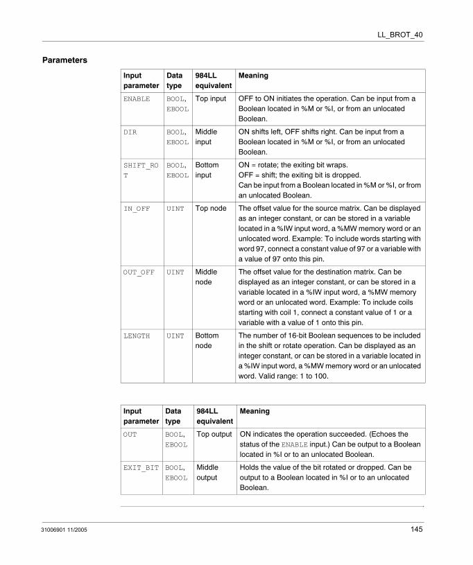
LL_BROT_40
Parameters
Input parameter
Data type
984LL equivalent
Meaning
ENABLE BOOL, EBOOL
Top input OFF to ON initiates the operation. Can be input from a Boolean located in %M or %I, or from an unlocated Boolean.
DIR BOOL, EBOOL
Middle input
ON shifts left, OFF shifts right. Can be input from a Boolean located in %M or %I, or from an unlocated Boolean.
SHIFT_ROT
BOOL, EBOOL
Bottom input
ON = rotate; the exiting bit wraps.OFF = shift; the exiting bit is dropped.Can be input from a Boolean located in %M or %I, or from an unlocated Boolean.
IN_OFF UINT Top node The offset value for the source matrix. Can be displayed as an integer constant, or can be stored in a variable located in a %IW input word, a %MW memory word or an unlocated word. Example: To include words starting with word 97, connect a constant value of 97 or a variable with a value of 97 onto this pin.
OUT_OFF UINT Middle node
The offset value for the destination matrix. Can be displayed as an integer constant, or can be stored in a variable located in a %IW input word, a %MW memory word or an unlocated word. Example: To include coils starting with coil 1, connect a constant value of 1 or a variable with a value of 1 onto this pin.
LENGTH UINT Bottom node
The number of 16-bit Boolean sequences to be included in the shift or rotate operation. Can be displayed as an integer constant, or can be stored in a variable located in a %IW input word, a %MW memory word or an unlocated word. Valid range: 1 to 100.
Input parameter
Data type
984LL equivalent
Meaning
OUT BOOL, EBOOL
Top output ON indicates the operation succeeded. (Echoes the status of the ENABLE input.) Can be output to a Boolean located in %I or to an unlocated Boolean.
EXIT_BIT BOOL, EBOOL
Middle output
Holds the value of the bit rotated or dropped. Can be output to a Boolean located in %I or to an unlocated Boolean.
31006901 11/2005 145

LL_BROT_40
146 31006901 11/2005
31006901 11/2005
32
LL_BROT_44: Bit Rotate (%MW - %MW)Description
Function Description
The LL_BROT_44 function block shifts or rotates the bit pattern in a source matrix, then writes the changed bit pattern into a destination matrix. The bit pattern shifts or rotates left or right by 1 position per scan, overwriting the destination matrix’s previous contents.
Both the source and destination matrices consist of 16-bit sequences made up of words located in %MW memory. The LENGTH value determines the number of words included in the shift or rotate operation. The location of the source matrix is defined by the IN_OFF offset value, and the location of the destination matrix is defined by the OUT_OFF offset value.
The operation begins when the input to the ENABLE pin is turned ON. If the DIR pin is turned ON, the source matrix will move left 1 position; if the DIR pin is turned OFF, the source matrix will move right 1 position.
If the SHFT_ROT bit is ON, the selected matrix will rotate and the exiting bit will wrap around to the opposite side of the source matrix. If the SHFT_ROT bit is OFF, the selected matrix will shift, the exiting bit will be dropped, and a 0 will fill-in on the opposite side of the source matrix.
The OUT output turns ON upon the successful completion of the operation. The EXIT_BIT output holds the value of the exiting bit.
EN and ENO can be configured as additional parameters.
147

LL_BROT_44
Representation in FBD
Representation in LD
Representation in IL
CAL LL_BROT_44_Instance (ENABLE:=Trigger, DIR:=LeftRight, SHIFT_ROT:=FuncSelect, IN_OFF:=Source, OUT_OFF:=Destination, LENGTH:=Integer1, OUT=>Success, EXIT_BIT=>Value)
Representation in ST
LL_BROT_44_Instance (ENABLE:=Trigger, DIR:=LeftRight, SHIFT_ROT:=FuncSelect, IN_OFF:=Source, OUT_OFF:=Destination, LENGTH:=Integer1, OUT=>Success, EXIT_BIT=>Value);
LL_BROT_44
TriggerLeftRight
LL_BROT_44_Instance
OUTENABLEDIRSHIFT_ROTIN_OFF
FuncSelectSource
SuccessEXIT_BIT Value
OUT_OFFDestinationLENGTHInteger1
Trigger
Source
ENOENSuccess
LL_BROT_44LL_BROT_44_Instance
OUTENABLE
IN_OFF
OUT_OFF
LENGTH
Destination
Integer1
ValueEXIT_BIT
FuncSelectSHIFT_ROT
LeftRightDIR
148 31006901 11/2005

LL_BROT_44
Parameters
Input parameter
Data type
984LL equivalent
Meaning
ENABLE BOOL, EBOOL
Top input OFF to ON initiates the operation. Can be input from a Boolean located in %M or %I, or from an unlocated Boolean.
DIR BOOL, EBOOL
Middle input
ON shifts left, OFF shifts right. Can be input from a Boolean located in %M or %I, or from an unlocated Boolean.
SHIFT_ROT BOOL, EBOOL
Bottom input
ON = rotate; the exiting bit wraps.OFF = shift; the exiting bit is dropped.Can be input from a Boolean located in %M or %I, or from an unlocated Boolean.
IN_OFF UINT Top node The offset value for the source matrix. Can be displayed as an integer constant, or can be stored in a variable located in a %IW input word, a %MW memory word or an unlocated word. Example: To include words starting with word 97, connect a constant value of 97 or a variable with a value of 97 onto this pin.
OUT_OFF UINT Middle node
The offset value for the destination matrix. Can be displayed as an integer constant, or can be stored in a variable located in a %IW input word, a %MW memory word or an unlocated word. Example: To include words starting with word 1, connect a constant value of 1 or a variable with a value of 1 onto this pin.
LENGTH UINT Bottom node
The number of 16-bit Boolean sequences to be included in the shift or rotate operation. Can be displayed as an integer constant, or can be stored in a variable located in a %IW input word, a %MW memory word or an unlocated word. Valid range: 1 to 100.
Output parameter
Data type
984LL equivalent
Meaning
OUT BOOL, EBOOL
Top output ON indicates the operation succeeded. (Echoes the status of the ENABLE input.) Can be output to a Boolean located in %I or to an unlocated Boolean.
EXIT_BIT BOOL, EBOOL
Middle output
Holds the value of the bit rotated or dropped. Can be output to a Boolean located in %I or to an unlocated Boolean.
31006901 11/2005 149

LL_BROT_44
150 31006901 11/2005
31006901 11/2005
33
LL_MBIT_X0: Modify Bit (%M)Description
Function Description
The LL_MBIT_X0 function block modifies bit locations within a data matrix - 1 bit location per scan - setting the bit(s) to 1 or clearing the bit(s) to 0.
The data matrix consists of 16-bit sequences in %M memory. The LENGTH value determines the number of 16-bit sequences included in the operation. The IN_OFF pin value, combined with the BITLOC pin value, identifies the specific bit location to set to 1 or clear to 0.
The operation begins when the input to the ENABLE pin is turned ON. If the SETBIT pin is turned ON, the value of the scanned bit will be set to 1; if the SETBIT pin is turned OFF, the value of the scanned bit will be set to 0.
If the INCPTR bit is ON - and if the BITLOC pin is tied to a located variable and not a constant - the BITLOC value will increment by 1 upon completion of the current scan.
The OUT output turns ON upon the successful completion of the operation. The SETBITO output echoes the state of the SETBIT value. The BADBIT output turns ON if the BITLOC value exceeds the size of the data matrix defined by the LENGTH value.
EN and ENO can be configured as additional parameters.
Note: The LL_MBIT_X0 function block will not write to and change the state of any EBOOL that has been forced in the Unity Pro Animation Table.
151
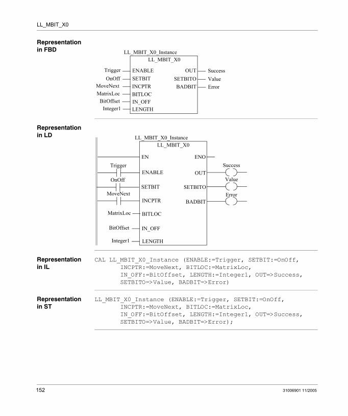
LL_MBIT_X0
Representation in FBD
Representation in LD
Representation in IL
CAL LL_MBIT_X0_Instance (ENABLE:=Trigger, SETBIT:=OnOff, INCPTR:=MoveNext, BITLOC:=MatrixLoc, IN_OFF:=BitOffset, LENGTH:=Integer1, OUT=>Success, SETBITO=>Value, BADBIT=>Error)
Representation in ST
LL_MBIT_X0_Instance (ENABLE:=Trigger, SETBIT:=OnOff, INCPTR:=MoveNext, BITLOC:=MatrixLoc, IN_OFF:=BitOffset, LENGTH:=Integer1, OUT=>Success, SETBITO=>Value, BADBIT=>Error);
LL_MBIT_X0
TriggerOnOff
LL_MBIT_X0_Instance
OUTENABLESETBITINCPTRBITLOC
MoveNextMatrixLoc
SuccessSETBITO Value
IN_OFFBitOffsetLENGTHInteger1
BADBIT Error
Trigger
MatrixLoc
ENOENSuccess
LL_MBIT_X0LL_MBIT_X0_Instance
OUTENABLE
BITLOC
IN_OFF
LENGTH
BitOffset
Integer1
ValueSETBITO
MoveNextINCPTR
OnOffSETBIT
BADBITError
152 31006901 11/2005
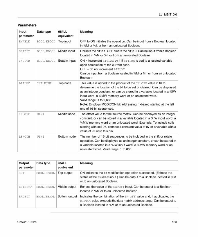
LL_MBIT_X0
Parameters
Input parameter
Data type 984LL equivalent
Meaning
ENABLE BOOL, EBOOL Top input OFF to ON initiates the operation. Can be input from a Boolean located in %M or %I, or from an unlocated Boolean.
SETBIT BOOL, EBOOL Middle input ON sets the bit to 1; OFF clears the bit to 0. Can be input from a Boolean located in %M or %I, or from an unlocated Boolean.
INCPTR BOOL, EBOOL Bottom input ON = increment BITLOC by 1 if BITLOC is tied to a located variable upon completion of the current scan. OFF = do not increment BITLOC. Can be input from a Boolean located in %M or %I, or from an unlocated Boolean.
BITLOC INT, UINT Top node This value is added to the product of the IN_OFF value x 16 to determine the location of the bit to be set or cleared. Can be displayed as an integer constant, or can be stored in a variable located in a %IW input word, a %MW memory word or an unlocated word. Valid range: 1 to 9,600Note: Employs MODICON bit addressing: 1-based starting at the left end of 16-bit sequences.
IN_OFF UINT Middle node The offset value for the source matrix. Can be displayed as an integer constant, or can be stored in a variable located in a %IW input word, a %MW memory word or an unlocated word. Example: To include coils starting with coil 97, connect a constant value of 97 or a variable with a value of 97 onto this pin.
LENGTH UINT Bottom node The number of 16-bit sequences to be included in the shift or rotate operation. Can be displayed as an integer constant, or can be stored in a variable located in a %IW input word, a %MW memory word or an unlocated word. Valid range: 1 to 600.
Output parameter
Data type 984LL equivalent
Meaning
OUT BOOL, EBOOL Top output ON indicates the bit modification operation succeeded. (Echoes the status of the ENABLE input.) Can be output to a Boolean located in %M or to an unlocated Boolean.
SETBITO BOOL, EBOOL Middle output Echoes the value of the SETBIT input. Can be output to a Boolean located in %M or to an unlocated Boolean.
BADBIT BOOL, EBOOL Bottom output Indicates the combination of the IN_OFF value and, if applicable, the BITLOC value exceeds the data matrix address range. Can be output to a Boolean located in %M or to an unlocated Boolean.
31006901 11/2005 153

LL_MBIT_X0
154 31006901 11/2005
31006901 11/2005
34
LL_MBIT_X4: Modify Bit (%MW)Description
Function Description
The LL_MBIT_X4 function block modifies bit locations within a data matrix - 1 bit location per scan - setting the bit(s) to 1 or clearing the bit(s) to 0.
The data matrix consists of 16-bit sequences in %MW memory. The LENGTH value determines the number of 16-bit sequences included in the operation. The IN_OFF pin value, combined with the BITLOC pin value, identifies the specific bit location to set to 1 or clear to 0.
The operation begins when the input to the ENABLE pin is turned ON. If the SETBIT pin is turned ON, the value of the scanned bit will be set to 1; if the SETBIT pin is turned OFF, the value of the scanned bit will be set to 0.
If the INCPTR bit is ON - and if the BITLOC pin is tied to a located variable and not a constant - the BITLOC value will increment by 1 upon completion of the current scan.
The OUT output turns ON upon the successful completion of the operation. The SETBITO output echoes the state of the SETBIT value. The BADBIT output turns ON if the BITLOC value exceeds the size of the data matrix defined by the LENGTH value.
EN and ENO can be configured as additional parameters.
155
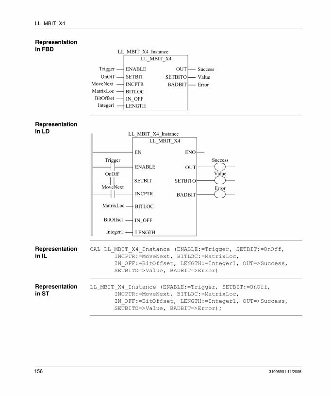
LL_MBIT_X4
Representation in FBD
Representation in LD
Representation in IL
CAL LL_MBIT_X4_Instance (ENABLE:=Trigger, SETBIT:=OnOff, INCPTR:=MoveNext, BITLOC:=MatrixLoc, IN_OFF:=BitOffset, LENGTH:=Integer1, OUT=>Success, SETBITO=>Value, BADBIT=>Error)
Representation in ST
LL_MBIT_X4_Instance (ENABLE:=Trigger, SETBIT:=OnOff, INCPTR:=MoveNext, BITLOC:=MatrixLoc, IN_OFF:=BitOffset, LENGTH:=Integer1, OUT=>Success, SETBITO=>Value, BADBIT=>Error);
LL_MBIT_X4
TriggerOnOff
LL_MBIT_X4_Instance
OUTENABLESETBITINCPTRBITLOC
MoveNextMatrixLoc
SuccessSETBITO Value
IN_OFFBitOffsetLENGTHInteger1
BADBIT Error
Trigger
MatrixLoc
ENOENSuccess
LL_MBIT_X4LL_MBIT_X4_Instance
OUTENABLE
BITLOC
IN_OFF
LENGTH
BitOffset
Integer1
ValueSETBITO
MoveNextINCPTR
OnOffSETBIT
BADBITError
156 31006901 11/2005
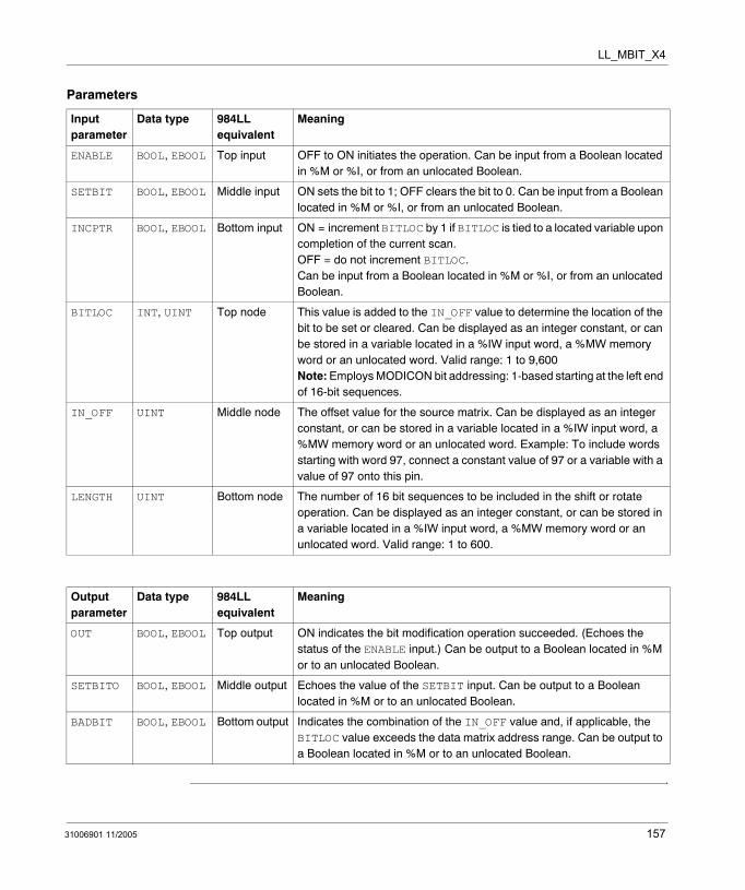
LL_MBIT_X4
Parameters
Input parameter
Data type 984LL equivalent
Meaning
ENABLE BOOL, EBOOL Top input OFF to ON initiates the operation. Can be input from a Boolean located in %M or %I, or from an unlocated Boolean.
SETBIT BOOL, EBOOL Middle input ON sets the bit to 1; OFF clears the bit to 0. Can be input from a Boolean located in %M or %I, or from an unlocated Boolean.
INCPTR BOOL, EBOOL Bottom input ON = increment BITLOC by 1 if BITLOC is tied to a located variable upon completion of the current scan.OFF = do not increment BITLOC.Can be input from a Boolean located in %M or %I, or from an unlocated Boolean.
BITLOC INT, UINT Top node This value is added to the IN_OFF value to determine the location of the bit to be set or cleared. Can be displayed as an integer constant, or can be stored in a variable located in a %IW input word, a %MW memory word or an unlocated word. Valid range: 1 to 9,600Note: Employs MODICON bit addressing: 1-based starting at the left end of 16-bit sequences.
IN_OFF UINT Middle node The offset value for the source matrix. Can be displayed as an integer constant, or can be stored in a variable located in a %IW input word, a %MW memory word or an unlocated word. Example: To include words starting with word 97, connect a constant value of 97 or a variable with a value of 97 onto this pin.
LENGTH UINT Bottom node The number of 16 bit sequences to be included in the shift or rotate operation. Can be displayed as an integer constant, or can be stored in a variable located in a %IW input word, a %MW memory word or an unlocated word. Valid range: 1 to 600.
Output parameter
Data type 984LL equivalent
Meaning
OUT BOOL, EBOOL Top output ON indicates the bit modification operation succeeded. (Echoes the status of the ENABLE input.) Can be output to a Boolean located in %M or to an unlocated Boolean.
SETBITO BOOL, EBOOL Middle output Echoes the value of the SETBIT input. Can be output to a Boolean located in %M or to an unlocated Boolean.
BADBIT BOOL, EBOOL Bottom output Indicates the combination of the IN_OFF value and, if applicable, the BITLOC value exceeds the data matrix address range. Can be output to a Boolean located in %M or to an unlocated Boolean.
31006901 11/2005 157

LL_MBIT_X4
158 31006901 11/2005
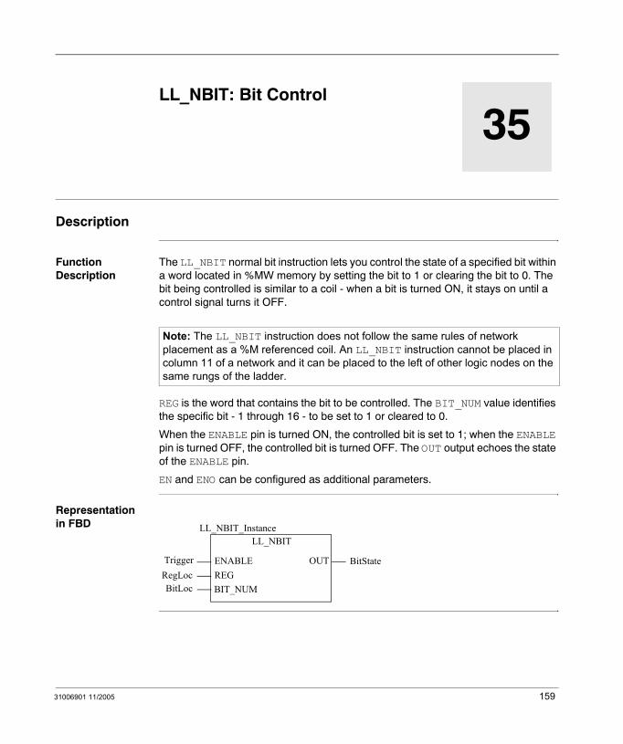
31006901 11/2005
35
LL_NBIT: Bit ControlDescription
Function Description
The LL_NBIT normal bit instruction lets you control the state of a specified bit within a word located in %MW memory by setting the bit to 1 or clearing the bit to 0. The bit being controlled is similar to a coil - when a bit is turned ON, it stays on until a control signal turns it OFF.
REG is the word that contains the bit to be controlled. The BIT_NUM value identifies the specific bit - 1 through 16 - to be set to 1 or cleared to 0.
When the ENABLE pin is turned ON, the controlled bit is set to 1; when the ENABLE pin is turned OFF, the controlled bit is turned OFF. The OUT output echoes the state of the ENABLE pin.
EN and ENO can be configured as additional parameters.
Representation in FBD
Note: The LL_NBIT instruction does not follow the same rules of network placement as a %M referenced coil. An LL_NBIT instruction cannot be placed in column 11 of a network and it can be placed to the left of other logic nodes on the same rungs of the ladder.
LL_NBIT
TriggerRegLoc
LL_NBIT_Instance
OUTENABLEREGBIT_NUMBitLoc
BitState
159
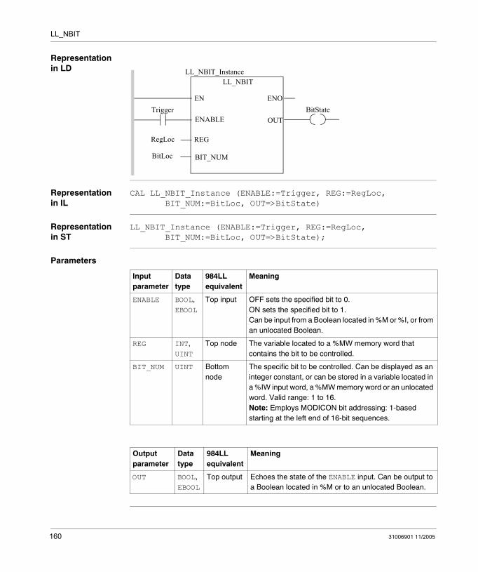
LL_NBIT
Representation in LD
Representation in IL
CAL LL_NBIT_Instance (ENABLE:=Trigger, REG:=RegLoc, BIT_NUM:=BitLoc, OUT=>BitState)
Representation in ST
LL_NBIT_Instance (ENABLE:=Trigger, REG:=RegLoc, BIT_NUM:=BitLoc, OUT=>BitState);
Parameters
Trigger
BitLoc
ENOENBitState
LL_NBITLL_NBIT_Instance
OUTENABLE
BIT_NUM
REGRegLoc
Input parameter
Data type
984LL equivalent
Meaning
ENABLE BOOL, EBOOL
Top input OFF sets the specified bit to 0.ON sets the specified bit to 1. Can be input from a Boolean located in %M or %I, or from an unlocated Boolean.
REG INT, UINT
Top node The variable located to a %MW memory word that contains the bit to be controlled.
BIT_NUM UINT Bottom node
The specific bit to be controlled. Can be displayed as an integer constant, or can be stored in a variable located in a %IW input word, a %MW memory word or an unlocated word. Valid range: 1 to 16.Note: Employs MODICON bit addressing: 1-based starting at the left end of 16-bit sequences.
Output parameter
Data type
984LL equivalent
Meaning
OUT BOOL, EBOOL
Top output Echoes the state of the ENABLE input. Can be output to a Boolean located in %M or to an unlocated Boolean.
160 31006901 11/2005
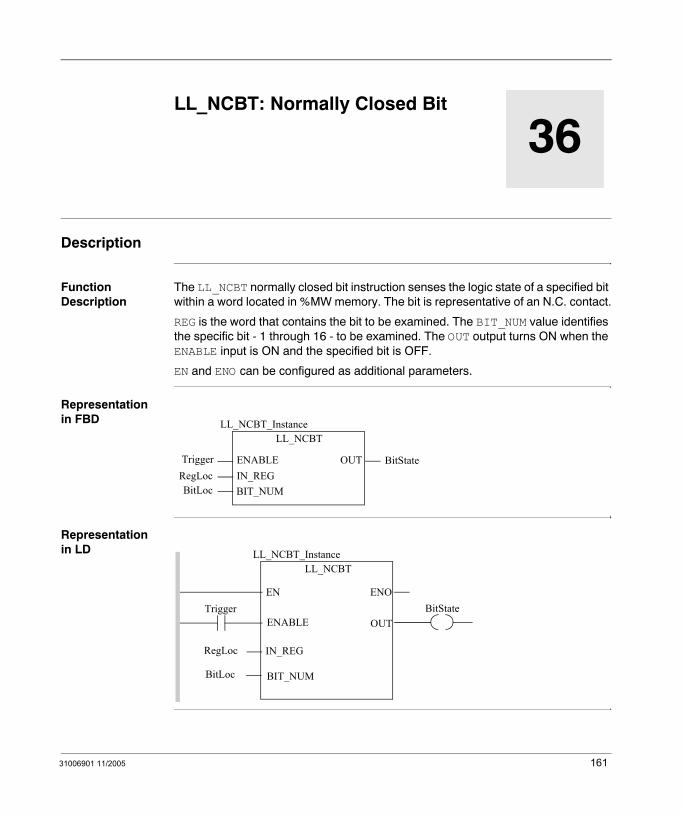
31006901 11/2005
36
LL_NCBT: Normally Closed BitDescription
Function Description
The LL_NCBT normally closed bit instruction senses the logic state of a specified bit within a word located in %MW memory. The bit is representative of an N.C. contact.
REG is the word that contains the bit to be examined. The BIT_NUM value identifies the specific bit - 1 through 16 - to be examined. The OUT output turns ON when the ENABLE input is ON and the specified bit is OFF.
EN and ENO can be configured as additional parameters.
Representation in FBD
Representation in LD
LL_NCBT
TriggerRegLoc
LL_NCBT_Instance
OUTENABLEIN_REGBIT_NUMBitLoc
BitState
Trigger
BitLoc
ENOENBitState
LL_NCBTLL_NCBT_Instance
OUTENABLE
BIT_NUM
IN_REGRegLoc
161
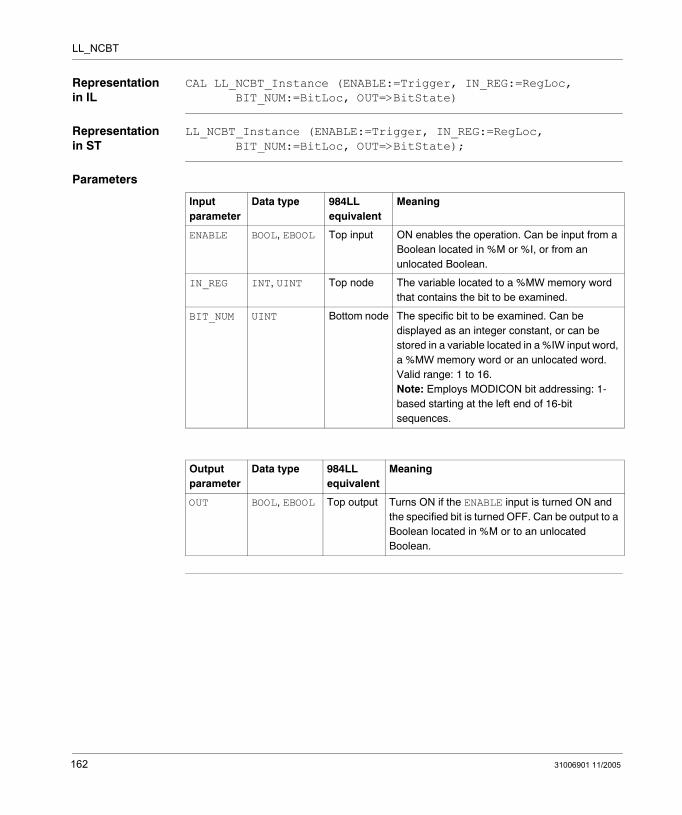
LL_NCBT
Representation in IL
CAL LL_NCBT_Instance (ENABLE:=Trigger, IN_REG:=RegLoc, BIT_NUM:=BitLoc, OUT=>BitState)
Representation in ST
LL_NCBT_Instance (ENABLE:=Trigger, IN_REG:=RegLoc, BIT_NUM:=BitLoc, OUT=>BitState);
Parameters
Input parameter
Data type 984LL equivalent
Meaning
ENABLE BOOL, EBOOL Top input ON enables the operation. Can be input from a Boolean located in %M or %I, or from an unlocated Boolean.
IN_REG INT, UINT Top node The variable located to a %MW memory word that contains the bit to be examined.
BIT_NUM UINT Bottom node The specific bit to be examined. Can be displayed as an integer constant, or can be stored in a variable located in a %IW input word, a %MW memory word or an unlocated word. Valid range: 1 to 16.Note: Employs MODICON bit addressing: 1-based starting at the left end of 16-bit sequences.
Output parameter
Data type 984LL equivalent
Meaning
OUT BOOL, EBOOL Top output Turns ON if the ENABLE input is turned ON and the specified bit is turned OFF. Can be output to a Boolean located in %M or to an unlocated Boolean.
162 31006901 11/2005
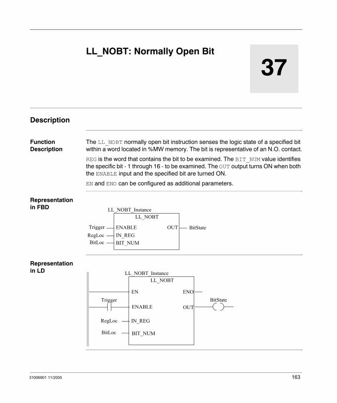
31006901 11/2005
37
LL_NOBT: Normally Open BitDescription
Function Description
The LL_NOBT normally open bit instruction senses the logic state of a specified bit within a word located in %MW memory. The bit is representative of an N.O. contact.
REG is the word that contains the bit to be examined. The BIT_NUM value identifies the specific bit - 1 through 16 - to be examined. The OUT output turns ON when both the ENABLE input and the specified bit are turned ON.
EN and ENO can be configured as additional parameters.
Representation in FBD
Representation in LD
LL_NOBT
TriggerRegLoc
LL_NOBT_Instance
OUTENABLEIN_REGBIT_NUMBitLoc
BitState
Trigger
BitLoc
ENOENBitState
LL_NOBTLL_NOBT_Instance
OUTENABLE
BIT_NUM
IN_REGRegLoc
163
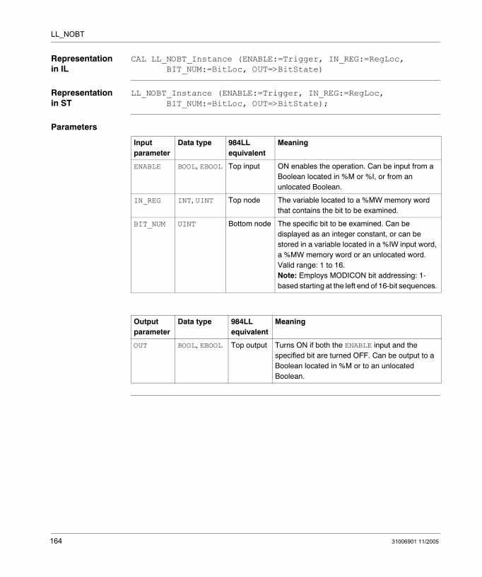
LL_NOBT
Representation in IL
CAL LL_NOBT_Instance (ENABLE:=Trigger, IN_REG:=RegLoc, BIT_NUM:=BitLoc, OUT=>BitState)
Representation in ST
LL_NOBT_Instance (ENABLE:=Trigger, IN_REG:=RegLoc, BIT_NUM:=BitLoc, OUT=>BitState);
Parameters
Input parameter
Data type 984LL equivalent
Meaning
ENABLE BOOL, EBOOL Top input ON enables the operation. Can be input from a Boolean located in %M or %I, or from an unlocated Boolean.
IN_REG INT, UINT Top node The variable located to a %MW memory word that contains the bit to be examined.
BIT_NUM UINT Bottom node The specific bit to be examined. Can be displayed as an integer constant, or can be stored in a variable located in a %IW input word, a %MW memory word or an unlocated word. Valid range: 1 to 16.Note: Employs MODICON bit addressing: 1-based starting at the left end of 16-bit sequences.
Output parameter
Data type 984LL equivalent
Meaning
OUT BOOL, EBOOL Top output Turns ON if both the ENABLE input and the specified bit are turned OFF. Can be output to a Boolean located in %M or to an unlocated Boolean.
164 31006901 11/2005
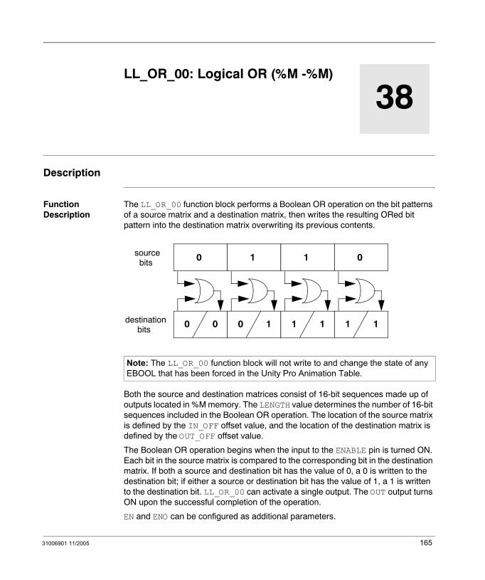
31006901 11/2005
38
LL_OR_00: Logical OR (%M -%M)Description
Function Description
The LL_OR_00 function block performs a Boolean OR operation on the bit patterns of a source matrix and a destination matrix, then writes the resulting ORed bit pattern into the destination matrix overwriting its previous contents.
Both the source and destination matrices consist of 16-bit sequences made up of outputs located in %M memory. The LENGTH value determines the number of 16-bit sequences included in the Boolean OR operation. The location of the source matrix is defined by the IN_OFF offset value, and the location of the destination matrix is defined by the OUT_OFF offset value.
The Boolean OR operation begins when the input to the ENABLE pin is turned ON. Each bit in the source matrix is compared to the corresponding bit in the destination matrix. If both a source and destination bit has the value of 0, a 0 is written to the destination bit; if either a source or destination bit has the value of 1, a 1 is written to the destination bit. LL_OR_00 can activate a single output. The OUT output turns ON upon the successful completion of the operation.
EN and ENO can be configured as additional parameters.
Note: The LL_OR_00 function block will not write to and change the state of any EBOOL that has been forced in the Unity Pro Animation Table.
0
0 0
1
0 1
sourcebits
destinationbits
1
1 1
0
1 1
165
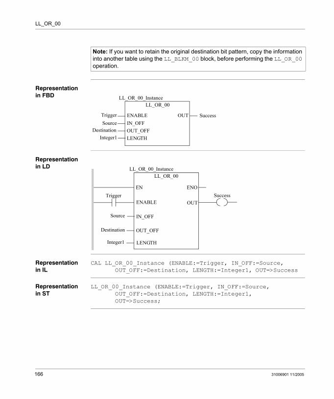
LL_OR_00
Representation in FBD
Representation in LD
Representation in IL
CAL LL_OR_00_Instance (ENABLE:=Trigger, IN_OFF:=Source, OUT_OFF:=Destination, LENGTH:=Integer1, OUT=>Success
Representation in ST
LL_OR_00_Instance (ENABLE:=Trigger, IN_OFF:=Source, OUT_OFF:=Destination, LENGTH:=Integer1, OUT=>Success;
Note: If you want to retain the original destination bit pattern, copy the information into another table using the LL_BLKM_00 block, before performing the LL_OR_00 operation.
LL_OR_00
TriggerSource
LL_OR_00_Instance
OUTENABLEIN_OFFOUT_OFFLENGTH
DestinationInteger1
Success
Trigger
Source
ENOENSuccess
LL_OR_00LL_OR_00_Instance
OUTENABLE
IN_OFF
OUT_OFF
LENGTH
Destination
Integer1
166 31006901 11/2005

LL_OR_00
Parameters
Input parameter
Data type 984LL equivalent
Meaning
ENABLE BOOL, EBOOL Top input OFF to ON initiates the operation. Can be input from a Boolean located in %M or %I, or from an unlocated Boolean.
IN_OFF UINT Top node The offset value for the source matrix. Can be displayed as an integer constant, or can be stored in a variable located in a %IW input word, a %MW memory word or an unlocated word. Example: To include coils starting with coil 97, connect a constant value of 97 or a variable with a value of 97 onto this pin.
OUT_OFF UINT Middle node The offset value for the destination matrix. Can be displayed as an integer constant, or can be stored in a variable located in a %IW input word, a %MW memory word or an unlocated word. Example: To include coils starting with coil 1, connect a constant value of 1 or a variable with a value of 1 onto this pin.
LENGTH UINT Bottom node The number of 16-bit Boolean sequences to be included in the Boolean OR operation. Can be displayed as an integer constant, or can be stored in a variable located in a %IW input word, a %MW memory word or an unlocated word. Valid range: 1 to 100.
Output parameter
Data type 984LL equivalent
Meaning
OUT BOOL, EBOOL Top output ON indicates the Boolean OR operation succeeded. (Echoes the status of the ENABLE input.) Can be output to a Boolean located in %I or to an unlocated Boolean.
31006901 11/2005 167

LL_OR_00
168 31006901 11/2005

31006901 11/2005
39
LL_OR_04: Logical OR (%M - %MW)Description
Function Description
The LL_OR_04 function block performs a Boolean OR operation on the bit patterns of a source matrix and a destination matrix, then writes the resulting ORed bit pattern into the destination matrix overwriting its previous contents.
Both the source and destination matrices consist of 16-bit sequences. The source matrix consists of outputs located in %M memory; the destination sequence consists of words located in %MW memory. The LENGTH value determines the number of 16-bit sequences included in the Boolean OR operation. The location of the source matrix is defined by the IN_OFF offset value, and the location of the destination matrix is defined by the OUT_OFF offset value.
The Boolean OR operation begins when the input to the ENABLE pin is turned ON. Each bit in the source matrix is compared to the corresponding bit in the destination matrix. If both a source and destination bit has the value of 0, a 0 is written to the destination bit; if either a source or destination bit has the value of 1, a 1 is written to the destination bit. LL_OR_04 can activate a single output. The OUT output turns ON upon the successful completion of the operation.
EN and ENO can be configured as additional parameters.
Note: If you want to retain the original destination bit pattern, copy the information into another table using the LL_BLKM_04 block, before performing the LL_OR_04 operation.
0
0 0
1
0 1
sourcebits
destinationbits
1
1 1
0
1 1
169

LL_OR_04
Representation in FBD
Representation in LD
Representation in IL
CAL LL_OR_04_Instance (ENABLE:=Trigger, IN_OFF:=Source, OUT_OFF:=Destination, LENGTH:=Integer1, OUT=>Success
Representation in ST
LL_OR_04_Instance (ENABLE:=Trigger, IN_OFF:=Source, OUT_OFF:=Destination, LENGTH:=Integer1, OUT=>Success;
LL_OR_04
TriggerSource
LL_OR_04_Instance
OUTENABLEIN_OFFOUT_OFFLENGTH
DestinationInteger1
Success
Trigger
Source
ENOENSuccess
LL_OR_04LL_OR_04_Instance
OUTENABLE
IN_OFF
OUT_OFF
LENGTH
Destination
Integer1
170 31006901 11/2005
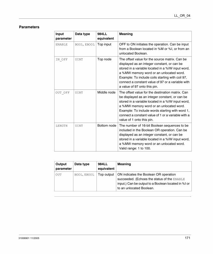
LL_OR_04
Parameters
Input parameter
Data type 984LL equivalent
Meaning
ENABLE BOOL, EBOOL Top input OFF to ON initiates the operation. Can be input from a Boolean located in %M or %I, or from an unlocated Boolean.
IN_OFF UINT Top node The offset value for the source matrix. Can be displayed as an integer constant, or can be stored in a variable located in a %IW input word, a %MW memory word or an unlocated word. Example: To include coils starting with coil 97, connect a constant value of 97 or a variable with a value of 97 onto this pin.
OUT_OFF UINT Middle node The offset value for the destination matrix. Can be displayed as an integer constant, or can be stored in a variable located in a %IW input word, a %MW memory word or an unlocated word. Example: To include words starting with word 1, connect a constant value of 1 or a variable with a value of 1 onto this pin.
LENGTH UINT Bottom node The number of 16-bit Boolean sequences to be included in the Boolean OR operation. Can be displayed as an integer constant, or can be stored in a variable located in a %IW input word, a %MW memory word or an unlocated word. Valid range: 1 to 100.
Output parameter
Data type 984LL equivalent
Meaning
OUT BOOL, EBOOL Top output ON indicates the Boolean OR operation succeeded. (Echoes the status of the ENABLE input.) Can be output to a Boolean located in %I or to an unlocated Boolean.
31006901 11/2005 171

LL_OR_04
172 31006901 11/2005

31006901 11/2005
40
LL_OR_10: Logical OR (%I - %M)Description
Function Description
The LL_OR_10 function block performs a Boolean OR operation on the bit patterns of a source matrix and a destination matrix, then writes the resulting ORed bit pattern into the destination matrix overwriting its previous contents.
Both the source and destination matrices consist of 16-bit sequences. The source matrix consists of %I inputs; the destination matrix consists of outputs located in %M memory. The LENGTH value determines the number of 16-bit sequences included in the Boolean OR operation. The location of the source matrix is defined by the IN_OFF offset value, and the location of the destination matrix is defined by the OUT_OFF offset value.
The Boolean OR operation begins when the input to the ENABLE pin is turned ON. Each bit in the source matrix is compared to the corresponding bit in the destination matrix. If both a source and destination bit has the value of 0, a 0 is written to the destination bit; if either a source or destination bit has the value of 1, a 1 is written to the destination bit. LL_OR_10 can activate a single output. The OUT output turns ON upon the successful completion of the operation.
EN and ENO can be configured as additional parameters.
Note: The LL_OR_10 function block will not write to and change the state of any EBOOL that has been forced in the Unity Pro Animation Table.
0
0 0
1
0 1
sourcebits
destinationbits
1
1 1
0
1 1
173
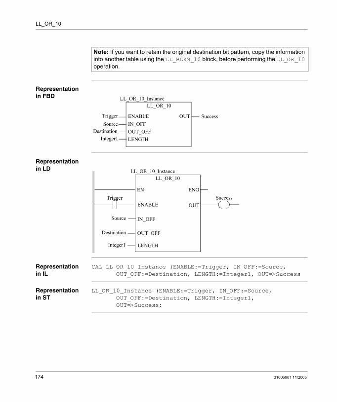
LL_OR_10
Representation in FBD
Representation in LD
Representation in IL
CAL LL_OR_10_Instance (ENABLE:=Trigger, IN_OFF:=Source, OUT_OFF:=Destination, LENGTH:=Integer1, OUT=>Success
Representation in ST
LL_OR_10_Instance (ENABLE:=Trigger, IN_OFF:=Source, OUT_OFF:=Destination, LENGTH:=Integer1, OUT=>Success;
Note: If you want to retain the original destination bit pattern, copy the information into another table using the LL_BLKM_10 block, before performing the LL_OR_10 operation.
LL_OR_10
TriggerSource
LL_OR_10_Instance
OUTENABLEIN_OFFOUT_OFFLENGTH
DestinationInteger1
Success
Trigger
Source
ENOENSuccess
LL_OR_10LL_OR_10_Instance
OUTENABLE
IN_OFF
OUT_OFF
LENGTH
Destination
Integer1
174 31006901 11/2005
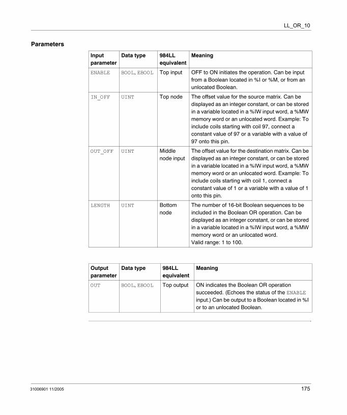
LL_OR_10
Parameters
Input parameter
Data type 984LL equivalent
Meaning
ENABLE BOOL, EBOOL Top input OFF to ON initiates the operation. Can be input from a Boolean located in %I or %M, or from an unlocated Boolean.
IN_OFF UINT Top node The offset value for the source matrix. Can be displayed as an integer constant, or can be stored in a variable located in a %IW input word, a %MW memory word or an unlocated word. Example: To include coils starting with coil 97, connect a constant value of 97 or a variable with a value of 97 onto this pin.
OUT_OFF UINT Middle node input
The offset value for the destination matrix. Can be displayed as an integer constant, or can be stored in a variable located in a %IW input word, a %MW memory word or an unlocated word. Example: To include coils starting with coil 1, connect a constant value of 1 or a variable with a value of 1 onto this pin.
LENGTH UINT Bottom node
The number of 16-bit Boolean sequences to be included in the Boolean OR operation. Can be displayed as an integer constant, or can be stored in a variable located in a %IW input word, a %MW memory word or an unlocated word. Valid range: 1 to 100.
Output parameter
Data type 984LL equivalent
Meaning
OUT BOOL, EBOOL Top output ON indicates the Boolean OR operation succeeded. (Echoes the status of the ENABLE input.) Can be output to a Boolean located in %I or to an unlocated Boolean.
31006901 11/2005 175

LL_OR_10
176 31006901 11/2005
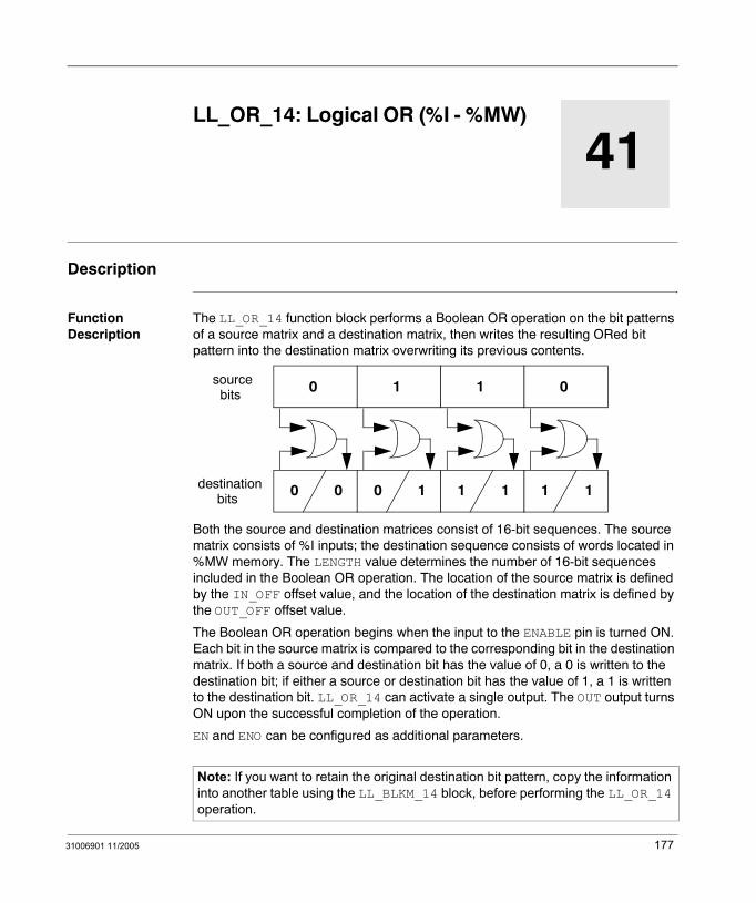
31006901 11/2005
41
LL_OR_14: Logical OR (%I - %MW)Description
Function Description
The LL_OR_14 function block performs a Boolean OR operation on the bit patterns of a source matrix and a destination matrix, then writes the resulting ORed bit pattern into the destination matrix overwriting its previous contents.
Both the source and destination matrices consist of 16-bit sequences. The source matrix consists of %I inputs; the destination sequence consists of words located in %MW memory. The LENGTH value determines the number of 16-bit sequences included in the Boolean OR operation. The location of the source matrix is defined by the IN_OFF offset value, and the location of the destination matrix is defined by the OUT_OFF offset value.
The Boolean OR operation begins when the input to the ENABLE pin is turned ON. Each bit in the source matrix is compared to the corresponding bit in the destination matrix. If both a source and destination bit has the value of 0, a 0 is written to the destination bit; if either a source or destination bit has the value of 1, a 1 is written to the destination bit. LL_OR_14 can activate a single output. The OUT output turns ON upon the successful completion of the operation.
EN and ENO can be configured as additional parameters.
Note: If you want to retain the original destination bit pattern, copy the information into another table using the LL_BLKM_14 block, before performing the LL_OR_14 operation.
0
0 0
1
0 1
sourcebits
destinationbits
1
1 1
0
1 1
177

LL_OR_14
Representation in FBD
Representation in LD
Representation in IL
CAL LL_OR_14_Instance (ENABLE:=Trigger, IN_OFF:=Source, OUT_OFF:=Destination, LENGTH:=Integer1, OUT=>Success
Representation in ST
LL_OR_14_Instance (ENABLE:=Trigger, IN_OFF:=Source, OUT_OFF:=Destination, LENGTH:=Integer1, OUT=>Success;
LL_OR_14
TriggerSource
LL_OR_14_Instance
OUTENABLEIN_OFFOUT_OFFLENGTH
DestinationInteger1
Success
Trigger
Source
ENOENSuccess
LL_OR_14LL_OR_14_Instance
OUTENABLE
IN_OFF
OUT_OFF
LENGTH
Destination
Integer1
178 31006901 11/2005

LL_OR_14
Parameters
Input parameter
Data type 984LL equivalent
Meaning
ENABLE BOOL, EBOOL Top input OFF to ON initiates the operation. Can be input from a Boolean located in %M or %I, or from an unlocated Boolean.
IN_OFF UINT Top node The offset value for the source matrix. Can be displayed as an integer constant, or can be stored in a variable located in a %IW input word, a %MW memory word or an unlocated word. Example: To include coils starting with coil 97, connect a constant value of 97 or a variable with a value of 97 onto this pin.
OUT_OFF UINT Middle node The offset value for the destination matrix. Can be displayed as an integer constant, or can be stored in a variable located in a %IW input word, a %MW memory word or an unlocated word. Example: To include words starting with word 1, connect a constant value of 1 or a variable with a value of 1 onto this pin.
LENGTH UINT Bottom node The number of 16-bit Boolean sequences to be included in the Boolean OR operation. Can be displayed as an integer constant, or can be stored in a variable located in a %IW input word, a %MW memory word or an unlocated word. Valid range: 1 to 100.
Output parameter
Data type 984LL equivalent
Meaning
OUT BOOL, EBOOL Top output ON indicates the Boolean OR operation succeeded. (Echoes the status of the ENABLE input.) Can be output to a Boolean located in %I or to an unlocated Boolean.
31006901 11/2005 179

LL_OR_14
180 31006901 11/2005
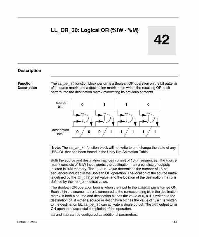
31006901 11/2005
42
LL_OR_30: Logical OR (%IW - %M)Description
Function Description
The LL_OR_30 function block performs a Boolean OR operation on the bit patterns of a source matrix and a destination matrix, then writes the resulting ORed bit pattern into the destination matrix overwriting its previous contents.
Both the source and destination matrices consist of 16-bit sequences. The source matrix consists of %IW input words; the destination matrix consists of outputs located in %M memory. The LENGTH value determines the number of 16-bit sequences included in the Boolean OR operation. The location of the source matrix is defined by the IN_OFF offset value, and the location of the destination matrix is defined by the OUT_OFF offset value.
The Boolean OR operation begins when the input to the ENABLE pin is turned ON. Each bit in the source matrix is compared to the corresponding bit in the destination matrix. If both a source and destination bit has the value of 0, a 0 is written to the destination bit; if either a source or destination bit has the value of 1, a 1 is written to the destination bit. LL_OR_30 can activate a single output. The OUT output turns ON upon the successful completion of the operation.
EN and ENO can be configured as additional parameters.
Note: The LL_OR_30 function block will not write to and change the state of any EBOOL that has been forced in the Unity Pro Animation Table.
0
0 0
1
0 1
sourcebits
destinationbits
1
1 1
0
1 1
181

LL_OR_30
Representation in FBD
Representation in LD
Representation in IL
CAL LL_OR_30_Instance (ENABLE:=Trigger, IN_OFF:=Source, OUT_OFF:=Destination, LENGTH:=Integer1, OUT=>Success
Representation in ST
LL_OR_30_Instance (ENABLE:=Trigger, IN_OFF:=Source, OUT_OFF:=Destination, LENGTH:=Integer1, OUT=>Success;
Note: If you want to retain the original destination bit pattern, copy the information into another table using the LL_BLKM_30 block, before performing the LL_OR_30 operation.
LL_OR_30
TriggerSource
LL_OR_30_Instance
OUTENABLEIN_OFFOUT_OFFLENGTH
DestinationInteger1
Success
Trigger
Source
ENOENSuccess
LL_OR_30LL_OR_30_Instance
OUTENABLE
IN_OFF
OUT_OFF
LENGTH
Destination
Integer1
182 31006901 11/2005
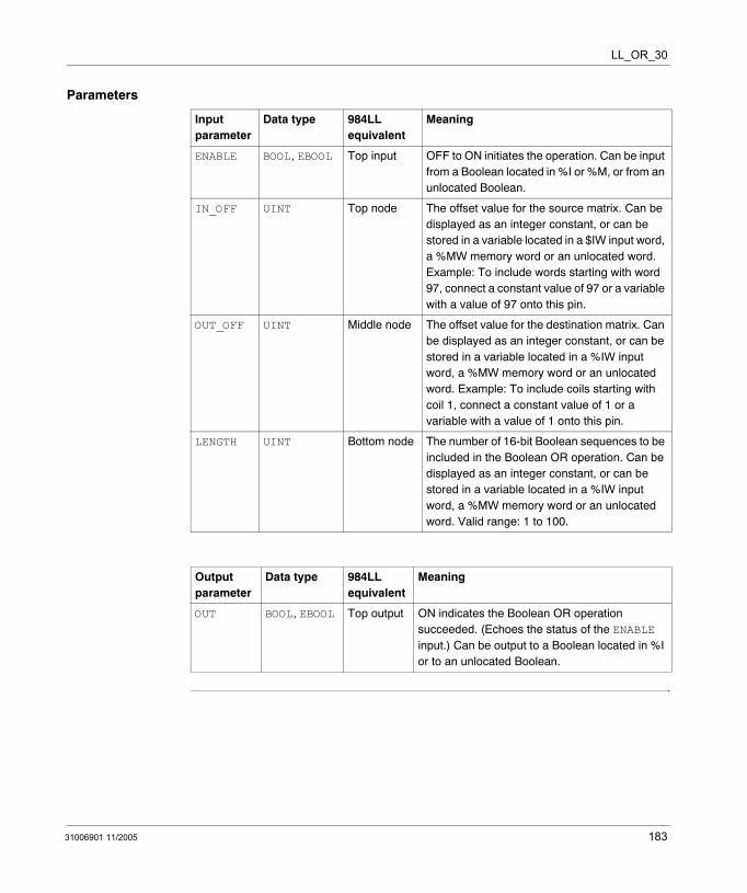
LL_OR_30
Parameters
Input parameter
Data type 984LL equivalent
Meaning
ENABLE BOOL, EBOOL Top input OFF to ON initiates the operation. Can be input from a Boolean located in %I or %M, or from an unlocated Boolean.
IN_OFF UINT Top node The offset value for the source matrix. Can be displayed as an integer constant, or can be stored in a variable located in a $IW input word, a %MW memory word or an unlocated word. Example: To include words starting with word 97, connect a constant value of 97 or a variable with a value of 97 onto this pin.
OUT_OFF UINT Middle node The offset value for the destination matrix. Can be displayed as an integer constant, or can be stored in a variable located in a %IW input word, a %MW memory word or an unlocated word. Example: To include coils starting with coil 1, connect a constant value of 1 or a variable with a value of 1 onto this pin.
LENGTH UINT Bottom node The number of 16-bit Boolean sequences to be included in the Boolean OR operation. Can be displayed as an integer constant, or can be stored in a variable located in a %IW input word, a %MW memory word or an unlocated word. Valid range: 1 to 100.
Output parameter
Data type 984LL equivalent
Meaning
OUT BOOL, EBOOL Top output ON indicates the Boolean OR operation succeeded. (Echoes the status of the ENABLE input.) Can be output to a Boolean located in %I or to an unlocated Boolean.
31006901 11/2005 183

LL_OR_30
184 31006901 11/2005

31006901 11/2005
43
LL_OR_34: Logical OR (%IW - %MW)Description
Function Description
The LL_OR_34 function block performs a Boolean OR operation on the bit patterns of a source matrix and a destination matrix, then writes the resulting ORed bit pattern into the destination matrix overwriting its previous contents.
Both the source and destination matrices consist of 16-bit sequences. The source matrix consists of %IW input words; the destination sequence consists of words located in %MW memory. The LENGTH value determines the number of 16-bit sequences included in the Boolean OR operation. The location of the source matrix is defined by the IN_OFF offset value, and the location of the destination matrix is defined by the OUT_OFF offset value.
The Boolean OR operation begins when the input to the ENABLE pin is turned ON. Each bit in the source matrix is compared to the corresponding bit in the destination matrix. If both a source and destination bit has the value of 0, a 0 is written to the destination bit; if either a source or destination bit has the value of 1, a 1 is written to the destination bit. LL_OR_34 can activate a single output. The OUT output turns ON upon the successful completion of the operation.
EN and ENO can be configured as additional parameters.
Note: If you want to retain the original destination bit pattern, copy the information into another table using the LL_BLKM_34 block, before performing the LL_OR_34 operation.
0
0 0
1
0 1
sourcebits
destinationbits
1
1 1
0
1 1
185
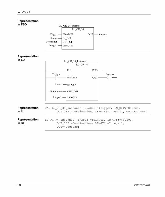
LL_OR_34
Representation in FBD
Representation in LD
Representation in IL
CAL LL_OR_34_Instance (ENABLE:=Trigger, IN_OFF:=Source, OUT_OFF:=Destination, LENGTH:=Integer1, OUT=>Success
Representation in ST
LL_OR_34_Instance (ENABLE:=Trigger, IN_OFF:=Source, OUT_OFF:=Destination, LENGTH:=Integer1, OUT=>Success;
LL_OR_34
TriggerSource
LL_OR_34_Instance
OUTENABLEIN_OFFOUT_OFFLENGTH
DestinationInteger1
Success
Trigger
Source
ENOENSuccess
LL_OR_34LL_OR_34_Instance
OUTENABLE
IN_OFF
OUT_OFF
LENGTH
Destination
Integer1
186 31006901 11/2005

LL_OR_34
Parameters
Input parameter
Data type 984LL equivalent
Meaning
ENABLE BOOL, EBOOL Top input OFF to ON initiates the operation. Can be input from a Boolean located in %M or %I, or from an unlocated Boolean.
IN_OFF UINT Top node The offset value for the source matrix. Can be displayed as an integer constant, or can be stored in a variable located in a %IW input word, a %MW memory word or an unlocated word. Example: To include words starting with word 97, connect a constant value of 97 or a variable with a value of 97 onto this pin.
OUT_OFF UINT Middle node The offset value for the destination matrix. Can be displayed as an integer constant, or can be stored in a variable located in a %IW input word, a %MW memory word or an unlocated word. Example: To include words starting with word 1, connect a constant value of 1 or a variable with a value of 1 onto this pin.
LENGTH UINT Bottom node The number of 16-bit Boolean sequences to be included in the Boolean OR operation. Can be displayed as an integer constant, or can be stored in a variable located in a %IW input word, a %MW memory word or an unlocated word. Valid range: 1 to 100.
Output parameter
Data type 984LL equivalent
Meaning
OUT BOOL, EBOOL Top output ON indicates the Boolean OR operation succeeded. (Echoes the status of the ENABLE input.) Can be output to a Boolean located in %I or to an unlocated Boolean.
31006901 11/2005 187

LL_OR_34
188 31006901 11/2005

31006901 11/2005
44
LL_OR_40: Logical OR (%MW - %M)Description
Function Description
The LL_OR_40 function block performs a Boolean OR operation on the bit patterns of a source matrix and a destination matrix, then writes the resulting ORed bit pattern into the destination matrix overwriting its previous contents.
Both the source and destination matrices consist of 16-bit sequences. The source matrix consists of words located in %MW memory; the destination matrix consists of outputs located in %M memory. The LENGTH value determines the number of 16-bit sequences included in the Boolean OR operation. The location of the source matrix is defined by the IN_OFF offset value, and the location of the destination matrix is defined by the OUT_OFF offset value.
The Boolean OR operation begins when the input to the ENABLE pin is turned ON. Each bit in the source matrix is compared to the corresponding bit in the destination matrix. If both a source and destination bit has the value of 0, a 0 is written to the destination bit; if either a source or destination bit has the value of 1, a 1 is written to the destination bit. LL_OR_40 can activate a single output. The OUT output turns ON upon the successful completion of the operation.
EN and ENO can be configured as additional parameters.
Note: The LL_OR_40 function block will not write to and change the state of any EBOOL that has been forced in the Unity Pro Animation Table.
0
0 0
1
0 1
sourcebits
destinationbits
1
1 1
0
1 1
189

LL_OR_40
Representation in FBD
Representation in LD
Representation in IL
CAL LL_OR_40_Instance (ENABLE:=Trigger, IN_OFF:=Source, OUT_OFF:=Destination, LENGTH:=Integer1, OUT=>Success
Representation in ST
LL_OR_40_Instance (ENABLE:=Trigger, IN_OFF:=Source, OUT_OFF:=Destination, LENGTH:=Integer1, OUT=>Success;
Note: If you want to retain the original destination bit pattern, copy the information into another table using the LL_BLKM_40 block, before performing the LL_OR_40 operation.
LL_OR_40
TriggerSource
LL_OR_40_Instance
OUTENABLEIN_OFFOUT_OFFLENGTH
DestinationInteger1
Success
Trigger
Source
ENOENSuccess
LL_OR_40LL_OR_40_Instance
OUTENABLE
IN_OFF
OUT_OFF
LENGTH
Destination
Integer1
190 31006901 11/2005

LL_OR_40
Parameters
Input parameter
Data type 984LL equivalent
Meaning
ENABLE BOOL, EBOOL Top input OFF to ON initiates the operation. Can be input from a Boolean located in %I or %M, or from an unlocated Boolean.
IN_OFF UINT Top node The offset value for the source matrix. Can be displayed as an integer constant, or can be stored in a variable located in a %IW input word, a %MW memory word or an unlocated word. Example: To include words starting with word 97, connect a constant value of 97 or a variable with a value of 97 onto this pin.
OUT_OFF UINT Middle node The offset value for the destination matrix. Can be displayed as an integer constant, or can be stored in a variable located in a %IW input word, a %MW memory word or an unlocated word. Example: To include coils starting with coil 1, connect a constant value of 1 or a variable with a value of 1 onto this pin.
LENGTH UINT Bottom node The number of 16-bit Boolean sequences to be included in the Boolean OR operation. Can be displayed as an integer constant, or can be stored in a variable located in a %IW input word, a %MW memory word or an unlocated word. Valid range: 1 to 100.
Output parameter
Data type 984LL equivalent
Meaning
OUT BOOL, EBOOL Top output ON indicates the Boolean OR operation succeeded. (Echoes the status of the ENABLE input.) Can be output to a Boolean located in %I or to an unlocated Boolean.
31006901 11/2005 191

LL_OR_40
192 31006901 11/2005
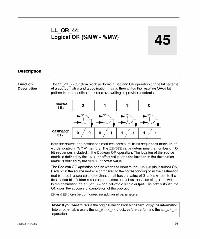
31006901 11/2005
45
LL_OR_44: Logical OR (%MW - %MW)Description
Function Description
The LL_OR_44 function block performs a Boolean OR operation on the bit patterns of a source matrix and a destination matrix, then writes the resulting ORed bit pattern into the destination matrix overwriting its previous contents.
Both the source and destination matrices consist of 16-bit sequences made up of words located in %MW memory. The LENGTH value determines the number of 16-bit sequences included in the Boolean OR operation. The location of the source matrix is defined by the IN_OFF offset value, and the location of the destination matrix is defined by the OUT_OFF offset value.
The Boolean OR operation begins when the input to the ENABLE pin is turned ON. Each bit in the source matrix is compared to the corresponding bit in the destination matrix. If both a source and destination bit has the value of 0, a 0 is written to the destination bit; if either a source or destination bit has the value of 1, a 1 is written to the destination bit. LL_OR_44 can activate a single output. The OUT output turns ON upon the successful completion of the operation.
EN and ENO can be configured as additional parameters.
Note: If you want to retain the original destination bit pattern, copy the information into another table using the LL_BLKM_44 block, before performing the LL_OR_44 operation.
0
0 0
1
0 1
sourcebits
destinationbits
1
1 1
0
1 1
193

LL_OR_44
Representation in FBD
Representation in LD
Representation in IL
CAL LL_OR_44_Instance (ENABLE:=Trigger, IN_OFF:=Source, OUT_OFF:=Destination, LENGTH:=Integer1, OUT=>Success
Representation in ST
LL_OR_44_Instance (ENABLE:=Trigger, IN_OFF:=Source, OUT_OFF:=Destination, LENGTH:=Integer1, OUT=>Success;
LL_OR_44
TriggerSource
LL_OR_44_Instance
OUTENABLEIN_OFFOUT_OFFLENGTH
DestinationInteger1
Success
Trigger
Source
ENOENSuccess
LL_OR_44LL_OR_44_Instance
OUTENABLE
IN_OFF
OUT_OFF
LENGTH
Destination
Integer1
194 31006901 11/2005
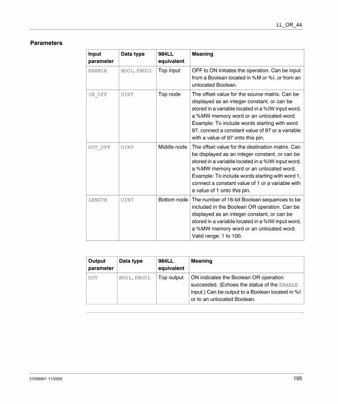
LL_OR_44
Parameters
Input parameter
Data type 984LL equivalent
Meaning
ENABLE BOOL, EBOOL Top input OFF to ON initiates the operation. Can be input from a Boolean located in %M or %I, or from an unlocated Boolean.
IN_OFF UINT Top node The offset value for the source matrix. Can be displayed as an integer constant, or can be stored in a variable located in a %IW input word, a %MW memory word or an unlocated word. Example: To include words starting with word 97, connect a constant value of 97 or a variable with a value of 97 onto this pin.
OUT_OFF UINT Middle node The offset value for the destination matrix. Can be displayed as an integer constant, or can be stored in a variable located in a %IW input word, a %MW memory word or an unlocated word. Example: To include words starting with word 1, connect a constant value of 1 or a variable with a value of 1 onto this pin.
LENGTH UINT Bottom node The number of 16-bit Boolean sequences to be included in the Boolean OR operation. Can be displayed as an integer constant, or can be stored in a variable located in a %IW input word, a %MW memory word or an unlocated word. Valid range: 1 to 100.
Output parameter
Data type 984LL equivalent
Meaning
OUT BOOL, EBOOL Top output ON indicates the Boolean OR operation succeeded. (Echoes the status of the ENABLE input.) Can be output to a Boolean located in %I or to an unlocated Boolean.
31006901 11/2005 195

LL_OR_44
196 31006901 11/2005
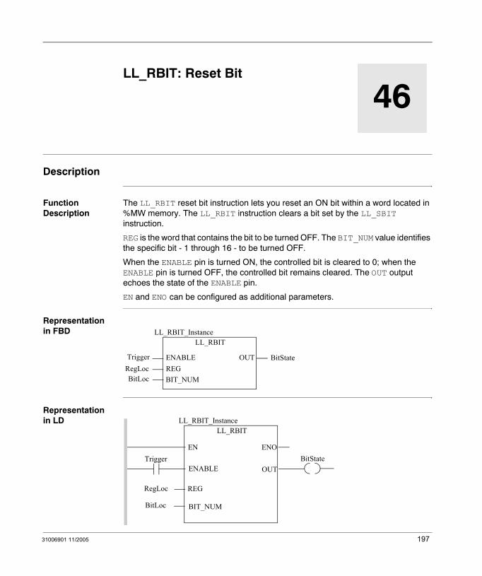
31006901 11/2005
46
LL_RBIT: Reset BitDescription
Function Description
The LL_RBIT reset bit instruction lets you reset an ON bit within a word located in %MW memory. The LL_RBIT instruction clears a bit set by the LL_SBIT instruction.
REG is the word that contains the bit to be turned OFF. The BIT_NUM value identifies the specific bit - 1 through 16 - to be turned OFF.
When the ENABLE pin is turned ON, the controlled bit is cleared to 0; when the ENABLE pin is turned OFF, the controlled bit remains cleared. The OUT output echoes the state of the ENABLE pin.
EN and ENO can be configured as additional parameters.
Representation in FBD
Representation in LD
LL_RBIT
TriggerRegLoc
LL_RBIT_Instance
OUTENABLEREGBIT_NUMBitLoc
BitState
Trigger
BitLoc
ENOENBitState
LL_RBITLL_RBIT_Instance
OUTENABLE
BIT_NUM
REGRegLoc
197
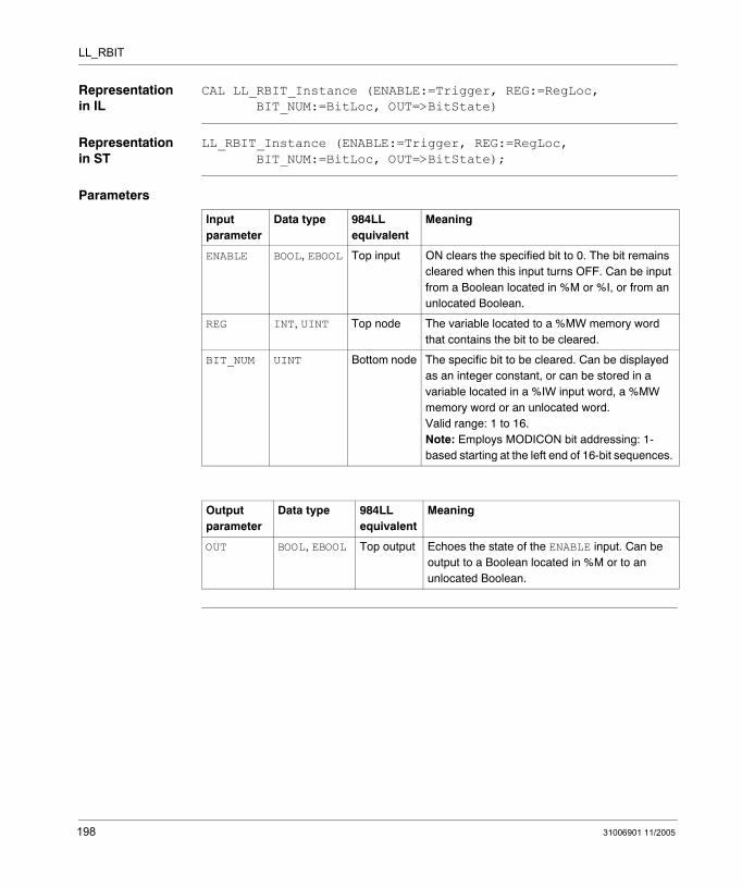
LL_RBIT
Representation in IL
CAL LL_RBIT_Instance (ENABLE:=Trigger, REG:=RegLoc, BIT_NUM:=BitLoc, OUT=>BitState)
Representation in ST
LL_RBIT_Instance (ENABLE:=Trigger, REG:=RegLoc, BIT_NUM:=BitLoc, OUT=>BitState);
Parameters
Input parameter
Data type 984LL equivalent
Meaning
ENABLE BOOL, EBOOL Top input ON clears the specified bit to 0. The bit remains cleared when this input turns OFF. Can be input from a Boolean located in %M or %I, or from an unlocated Boolean.
REG INT, UINT Top node The variable located to a %MW memory word that contains the bit to be cleared.
BIT_NUM UINT Bottom node The specific bit to be cleared. Can be displayed as an integer constant, or can be stored in a variable located in a %IW input word, a %MW memory word or an unlocated word. Valid range: 1 to 16.Note: Employs MODICON bit addressing: 1-based starting at the left end of 16-bit sequences.
Output parameter
Data type 984LL equivalent
Meaning
OUT BOOL, EBOOL Top output Echoes the state of the ENABLE input. Can be output to a Boolean located in %M or to an unlocated Boolean.
198 31006901 11/2005
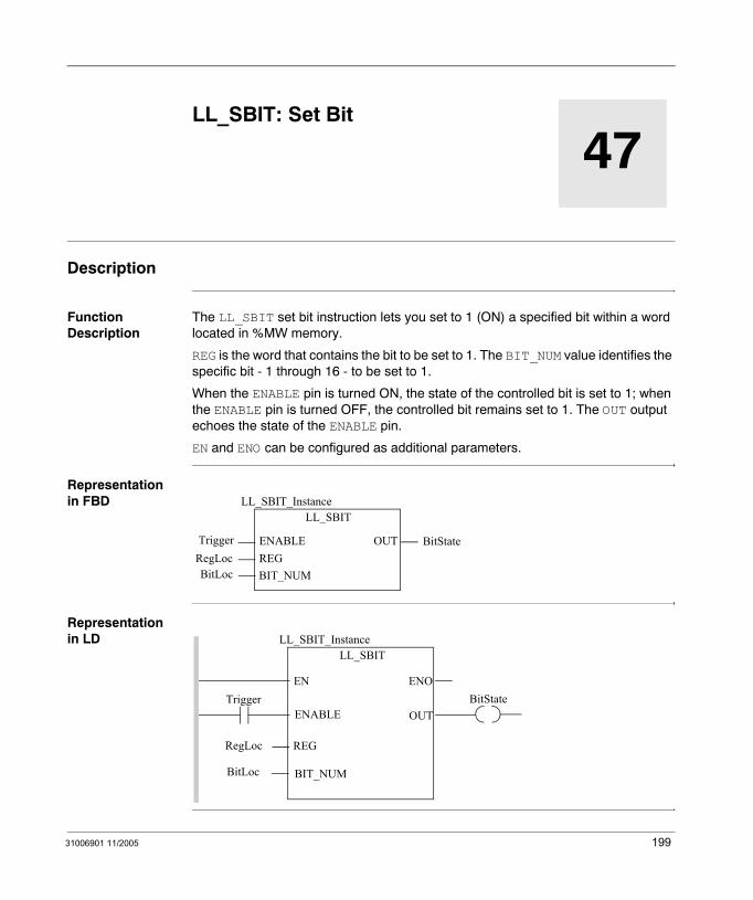
31006901 11/2005
47
LL_SBIT: Set BitDescription
Function Description
The LL_SBIT set bit instruction lets you set to 1 (ON) a specified bit within a word located in %MW memory.
REG is the word that contains the bit to be set to 1. The BIT_NUM value identifies the specific bit - 1 through 16 - to be set to 1.
When the ENABLE pin is turned ON, the state of the controlled bit is set to 1; when the ENABLE pin is turned OFF, the controlled bit remains set to 1. The OUT output echoes the state of the ENABLE pin.
EN and ENO can be configured as additional parameters.
Representation in FBD
Representation in LD
LL_SBIT
TriggerRegLoc
LL_SBIT_Instance
OUTENABLEREGBIT_NUMBitLoc
BitState
Trigger
BitLoc
ENOENBitState
LL_SBITLL_SBIT_Instance
OUTENABLE
BIT_NUM
REGRegLoc
199
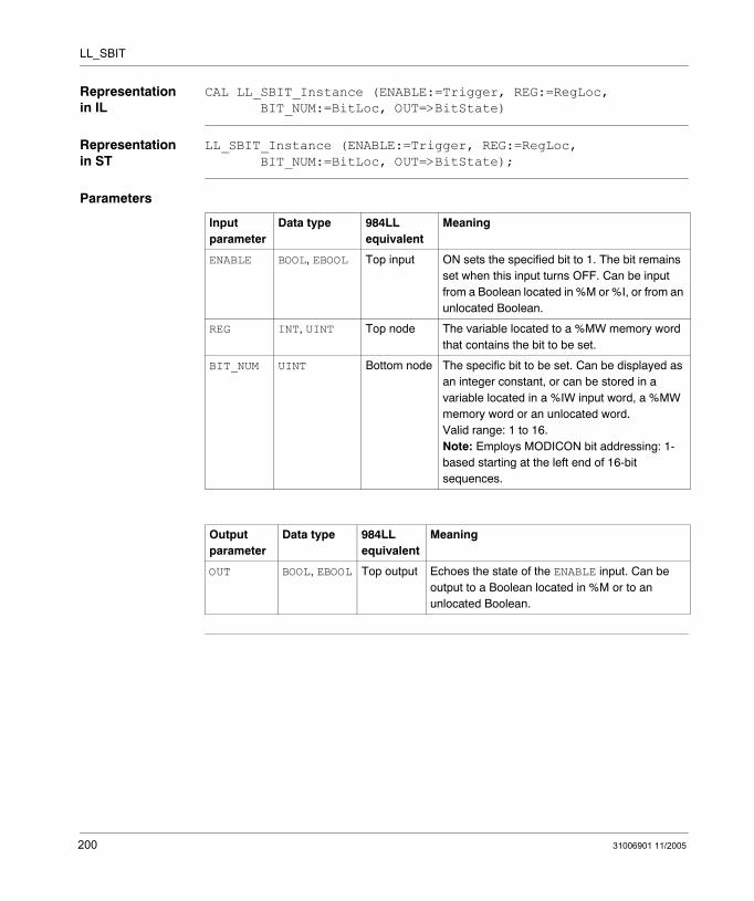
LL_SBIT
Representation in IL
CAL LL_SBIT_Instance (ENABLE:=Trigger, REG:=RegLoc, BIT_NUM:=BitLoc, OUT=>BitState)
Representation in ST
LL_SBIT_Instance (ENABLE:=Trigger, REG:=RegLoc, BIT_NUM:=BitLoc, OUT=>BitState);
Parameters
Input parameter
Data type 984LL equivalent
Meaning
ENABLE BOOL, EBOOL Top input ON sets the specified bit to 1. The bit remains set when this input turns OFF. Can be input from a Boolean located in %M or %I, or from an unlocated Boolean.
REG INT, UINT Top node The variable located to a %MW memory word that contains the bit to be set.
BIT_NUM UINT Bottom node The specific bit to be set. Can be displayed as an integer constant, or can be stored in a variable located in a %IW input word, a %MW memory word or an unlocated word. Valid range: 1 to 16.Note: Employs MODICON bit addressing: 1-based starting at the left end of 16-bit sequences.
Output parameter
Data type 984LL equivalent
Meaning
OUT BOOL, EBOOL Top output Echoes the state of the ENABLE input. Can be output to a Boolean located in %M or to an unlocated Boolean.
200 31006901 11/2005
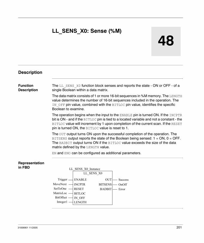
31006901 11/2005
48
LL_SENS_X0: Sense (%M)Description
Function Description
The LL_SENS_X0 function block senses and reports the state - ON or OFF - of a single Boolean within a data matrix.
The data matrix consists of 1 or more 16-bit sequences in %M memory. The LENGTH value determines the number of 16-bit sequences included in the operation. The IN_OFF pin value, combined with the BITLOC pin value, identifies the specific Boolean to examine.
The operation begins when the input to the ENABLE pin is turned ON. If the INCPTR bit is ON - and if the BITLOC pin is tied to a located variable and not a constant - the BITLOC value will increment by 1 upon completion of the current scan. If the RESET pin is turned ON, the BITLOC value is reset to 1.
The OUT output turns ON upon the successful completion of the operation. The BITSENS output reports the state of the Boolean being sensed: 1 = ON, 0 = OFF. The BADBIT output turns ON if the BITLOC value exceeds the size of the data matrix defined by the LENGTH value.
EN and ENO can be configured as additional parameters.
Representation in FBD
LL_SENS_X0
Trigger
LL_SENS_X0_Instance
OUTENABLE
RESETBITLOC
SetToOneMatrixLoc
SuccessBITSENS OnOff
IN_OFFBitOffsetLENGTHInteger1
BADBIT ErrorINCPTRMoveNext
201
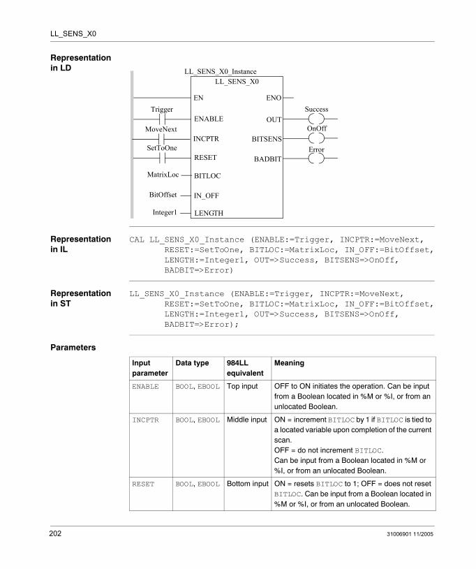
LL_SENS_X0
Representation in LD
Representation in IL
CAL LL_SENS_X0_Instance (ENABLE:=Trigger, INCPTR:=MoveNext,RESET:=SetToOne, BITLOC:=MatrixLoc, IN_OFF:=BitOffset,LENGTH:=Integer1, OUT=>Success, BITSENS=>OnOff, BADBIT=>Error)
Representation in ST
LL_SENS_X0_Instance (ENABLE:=Trigger, INCPTR:=MoveNext,RESET:=SetToOne, BITLOC:=MatrixLoc, IN_OFF:=BitOffset,LENGTH:=Integer1, OUT=>Success, BITSENS=>OnOff, BADBIT=>Error);
Parameters
Trigger
MatrixLoc
ENOENSuccess
LL_SENS_X0LL_SENS_X0_Instance
OUTENABLE
BITLOC
IN_OFF
LENGTH
BitOffset
Integer1
OnOffBITSENS
SetToOneRESET
MoveNextINCPTR
BADBITError
Input parameter
Data type 984LL equivalent
Meaning
ENABLE BOOL, EBOOL Top input OFF to ON initiates the operation. Can be input from a Boolean located in %M or %I, or from an unlocated Boolean.
INCPTR BOOL, EBOOL Middle input ON = increment BITLOC by 1 if BITLOC is tied to a located variable upon completion of the current scan.OFF = do not increment BITLOC.Can be input from a Boolean located in %M or %I, or from an unlocated Boolean.
RESET BOOL, EBOOL Bottom input ON = resets BITLOC to 1; OFF = does not reset BITLOC. Can be input from a Boolean located in %M or %I, or from an unlocated Boolean.
202 31006901 11/2005
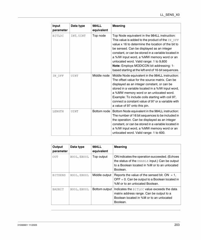
LL_SENS_X0
BITLOC INT, UINT Top node Top Node equivalent in the 984LL instruction: This value is added to the product of the IN_OFF value x 16 to determine the location of the bit to be sensed. Can be displayed as an integer constant, or can be stored in a variable located in a %IW input word, a %MW memory word or an unlocated word. Valid range: 1 to 9,600Note: Employs MODICON bit addressing: 1-based starting at the left end of 16-bit sequences.
IN_OFF UINT Middle node Middle Node equivalent in the 984LL instruction: The offset value for the source matrix. Can be displayed as an integer constant, or can be stored in a variable located in a %IW input word, a %MW memory word or an unlocated word. Example: To include coils starting with coil 97, connect a constant value of 97 or a variable with a value of 97 onto this pin.
LENGTH UINT Bottom node Bottom Node equivalent in the 984LL instruction: The number of 16 bit sequences to be included in the operation. Can be displayed as an integer constant, or can be stored in a variable located in a %IW input word, a %MW memory word or an unlocated word. Valid range: 1 to 600.
Output parameter
Data type 984LL equivalent
Meaning
OUT BOOL, EBOOL Top output ON indicates the operation succeeded. (Echoes the status of the ENABLE input.) Can be output to a Boolean located in %M or to an unlocated Boolean.
BITSENS BOOL, EBOOL Middle output Reports the value of the sensed bit. ON = 1, OFF = 0. Can be output to a Boolean located in %M or to an unlocated Boolean.
BADBIT BOOL, EBOOL Bottom output Indicates the BITLOC value exceeds the data matrix address range. Can be output to a Boolean located in %M or to an unlocated Boolean.
Input parameter
Data type 984LL equivalent
Meaning
31006901 11/2005 203

LL_SENS_X0
204 31006901 11/2005

31006901 11/2005
49
LL_SENS_X1: Sense (%I)Description
Function Description
The LL_SENS_X1 function block senses and reports the state - ON or OFF - of a single Boolean within a data matrix.
The data matrix consists of 1 or more 16-bit sequences of %I input bits. The LENGTH value determines the number of 16-bit sequences included in the operation. The IN_OFF pin value, combined with the BITLOC pin value, identifies the specific Boolean to examine.
The operation begins when the input to the ENABLE pin is turned ON. If the INCPTR bit is ON - and if the BITLOC pin is tied to a located variable and not a constant - the BITLOC value will increment by 1 upon completion of the current scan. If the RESET pin is turned ON, the BITLOC value is reset to 1.
The OUT output turns ON upon the successful completion of the operation. The BITSENS output reports the state of the Boolean being sensed: 1 = ON, 0 = OFF. The BADBIT output turns ON if the BITLOC value exceeds the size of the data matrix defined by the LENGTH value.
EN and ENO can be configured as additional parameters.
Representation in FBD
LL_SENS_X1
Trigger
LL_SENS_X1_Instance
OUTENABLE
RESETBITLOC
SetToOneMatrixLoc
SuccessBITSENS OnOff
IN_OFFBitOffsetLENGTHInteger1
BADBIT ErrorINCPTRMoveNext
205
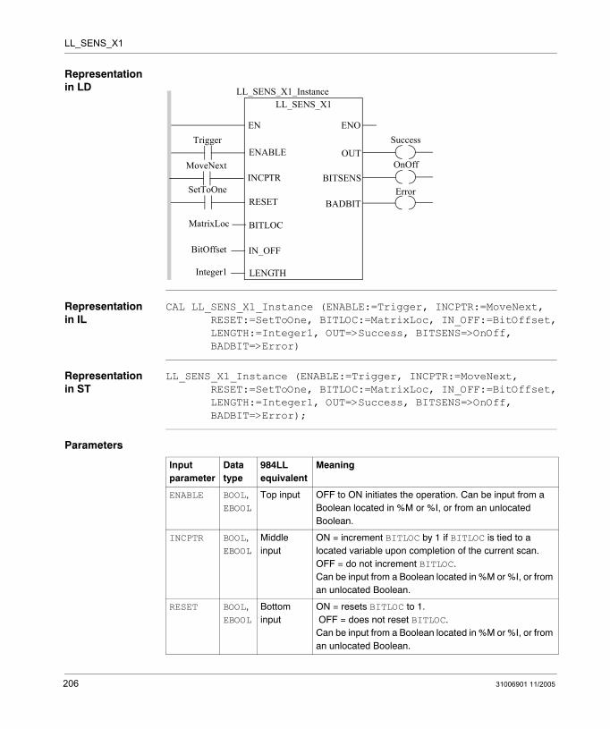
LL_SENS_X1
Representation in LD
Representation in IL
CAL LL_SENS_X1_Instance (ENABLE:=Trigger, INCPTR:=MoveNext,RESET:=SetToOne, BITLOC:=MatrixLoc, IN_OFF:=BitOffset,LENGTH:=Integer1, OUT=>Success, BITSENS=>OnOff, BADBIT=>Error)
Representation in ST
LL_SENS_X1_Instance (ENABLE:=Trigger, INCPTR:=MoveNext,RESET:=SetToOne, BITLOC:=MatrixLoc, IN_OFF:=BitOffset,LENGTH:=Integer1, OUT=>Success, BITSENS=>OnOff, BADBIT=>Error);
Parameters
Trigger
MatrixLoc
ENOENSuccess
LL_SENS_X1LL_SENS_X1_Instance
OUTENABLE
BITLOC
IN_OFF
LENGTH
BitOffset
Integer1
OnOffBITSENS
SetToOneRESET
MoveNextINCPTR
BADBITError
Input parameter
Data type
984LL equivalent
Meaning
ENABLE BOOL, EBOOL
Top input OFF to ON initiates the operation. Can be input from a Boolean located in %M or %I, or from an unlocated Boolean.
INCPTR BOOL, EBOOL
Middle input
ON = increment BITLOC by 1 if BITLOC is tied to a located variable upon completion of the current scan.OFF = do not increment BITLOC. Can be input from a Boolean located in %M or %I, or from an unlocated Boolean.
RESET BOOL, EBOOL
Bottom input
ON = resets BITLOC to 1. OFF = does not reset BITLOC. Can be input from a Boolean located in %M or %I, or from an unlocated Boolean.
206 31006901 11/2005
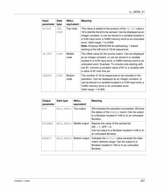
LL_SENS_X1
BITLOC INT, UINT
Top node This value is added to the product of the IN_OFF value x 16 to identify the bit to be sensed. Can be displayed as an integer constant, or can be stored in a variable located in a %IW input word, a %MW memory word or an unlocated word. Valid range: 1 to 9,600Note: Employs MODICON bit addressing: 1-based starting at the left end of 16-bit sequences.
IN_OFF UINT Middle node
The offset value for the source matrix. Can be displayed as an integer constant, or can be stored in a variable located in a %IW input word, a %MW memory word or an unlocated word. Example: To include coils starting with coil 97, connect a constant value of 97 or a variable with a value of 97 onto this pin.
LENGTH UINT Bottom node
The number of 16 bit sequences to be included in the operation. Can be displayed as an integer constant, or can be stored in a variable located in a %IW input word, a %MW memory word or an unlocated word. Valid range: 1 to 600.
Output parameter
Data type 984LL equivalent
Meaning
OUT BOOL, EBOOL Top output ON indicates the operation succeeded. (Echoes the status of the ENABLE input.) Can be output to a Boolean located in %M or to an unlocated Boolean.
BITSENS BOOL, EBOOL Middle output Reports the value of the sensed bit.ON = 1, OFF = 0.Can be output to a Boolean located in %M or to an unlocated Boolean.
BADBIT BOOL, EBOOL Bottom output Indicates the BITLOC value exceeds the data matrix address range. Can be output to a Boolean located in %M or to an unlocated Boolean.
Input parameter
Data type
984LL equivalent
Meaning
31006901 11/2005 207

LL_SENS_X1
208 31006901 11/2005
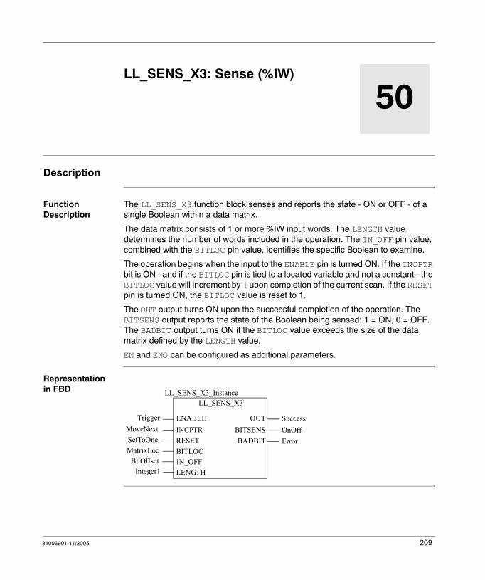
31006901 11/2005
50
LL_SENS_X3: Sense (%IW)Description
Function Description
The LL_SENS_X3 function block senses and reports the state - ON or OFF - of a single Boolean within a data matrix.
The data matrix consists of 1 or more %IW input words. The LENGTH value determines the number of words included in the operation. The IN_OFF pin value, combined with the BITLOC pin value, identifies the specific Boolean to examine.
The operation begins when the input to the ENABLE pin is turned ON. If the INCPTR bit is ON - and if the BITLOC pin is tied to a located variable and not a constant - the BITLOC value will increment by 1 upon completion of the current scan. If the RESET pin is turned ON, the BITLOC value is reset to 1.
The OUT output turns ON upon the successful completion of the operation. The BITSENS output reports the state of the Boolean being sensed: 1 = ON, 0 = OFF. The BADBIT output turns ON if the BITLOC value exceeds the size of the data matrix defined by the LENGTH value.
EN and ENO can be configured as additional parameters.
Representation in FBD
LL_SENS_X3
Trigger
LL_SENS_X3_Instance
OUTENABLE
RESETBITLOC
SetToOneMatrixLoc
SuccessBITSENS OnOff
IN_OFFBitOffsetLENGTHInteger1
BADBIT ErrorINCPTRMoveNext
209
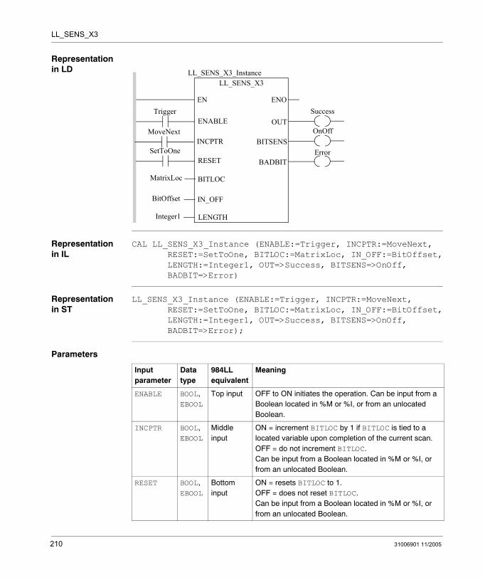
LL_SENS_X3
Representation in LD
Representation in IL
CAL LL_SENS_X3_Instance (ENABLE:=Trigger, INCPTR:=MoveNext,RESET:=SetToOne, BITLOC:=MatrixLoc, IN_OFF:=BitOffset,LENGTH:=Integer1, OUT=>Success, BITSENS=>OnOff, BADBIT=>Error)
Representation in ST
LL_SENS_X3_Instance (ENABLE:=Trigger, INCPTR:=MoveNext,RESET:=SetToOne, BITLOC:=MatrixLoc, IN_OFF:=BitOffset,LENGTH:=Integer1, OUT=>Success, BITSENS=>OnOff, BADBIT=>Error);
Parameters
Trigger
MatrixLoc
ENOENSuccess
LL_SENS_X3LL_SENS_X3_Instance
OUTENABLE
BITLOC
IN_OFF
LENGTH
BitOffset
Integer1
OnOffBITSENS
SetToOneRESET
MoveNextINCPTR
BADBITError
Input parameter
Data type
984LL equivalent
Meaning
ENABLE BOOL, EBOOL
Top input OFF to ON initiates the operation. Can be input from a Boolean located in %M or %I, or from an unlocated Boolean.
INCPTR BOOL, EBOOL
Middle input
ON = increment BITLOC by 1 if BITLOC is tied to a located variable upon completion of the current scan.OFF = do not increment BITLOC.Can be input from a Boolean located in %M or %I, or from an unlocated Boolean.
RESET BOOL, EBOOL
Bottom input
ON = resets BITLOC to 1.OFF = does not reset BITLOC. Can be input from a Boolean located in %M or %I, or from an unlocated Boolean.
210 31006901 11/2005
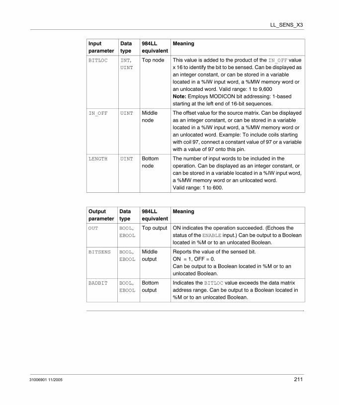
LL_SENS_X3
BITLOC INT, UINT
Top node This value is added to the product of the IN_OFF value x 16 to identify the bit to be sensed. Can be displayed as an integer constant, or can be stored in a variable located in a %IW input word, a %MW memory word or an unlocated word. Valid range: 1 to 9,600Note: Employs MODICON bit addressing: 1-based starting at the left end of 16-bit sequences.
IN_OFF UINT Middle node
The offset value for the source matrix. Can be displayed as an integer constant, or can be stored in a variable located in a %IW input word, a %MW memory word or an unlocated word. Example: To include coils starting with coil 97, connect a constant value of 97 or a variable with a value of 97 onto this pin.
LENGTH UINT Bottom node
The number of input words to be included in the operation. Can be displayed as an integer constant, or can be stored in a variable located in a %IW input word, a %MW memory word or an unlocated word. Valid range: 1 to 600.
Output parameter
Data type
984LL equivalent
Meaning
OUT BOOL, EBOOL
Top output ON indicates the operation succeeded. (Echoes the status of the ENABLE input.) Can be output to a Boolean located in %M or to an unlocated Boolean.
BITSENS BOOL, EBOOL
Middle output
Reports the value of the sensed bit. ON = 1, OFF = 0. Can be output to a Boolean located in %M or to an unlocated Boolean.
BADBIT BOOL, EBOOL
Bottom output
Indicates the BITLOC value exceeds the data matrix address range. Can be output to a Boolean located in %M or to an unlocated Boolean.
Input parameter
Data type
984LL equivalent
Meaning
31006901 11/2005 211

LL_SENS_X3
212 31006901 11/2005
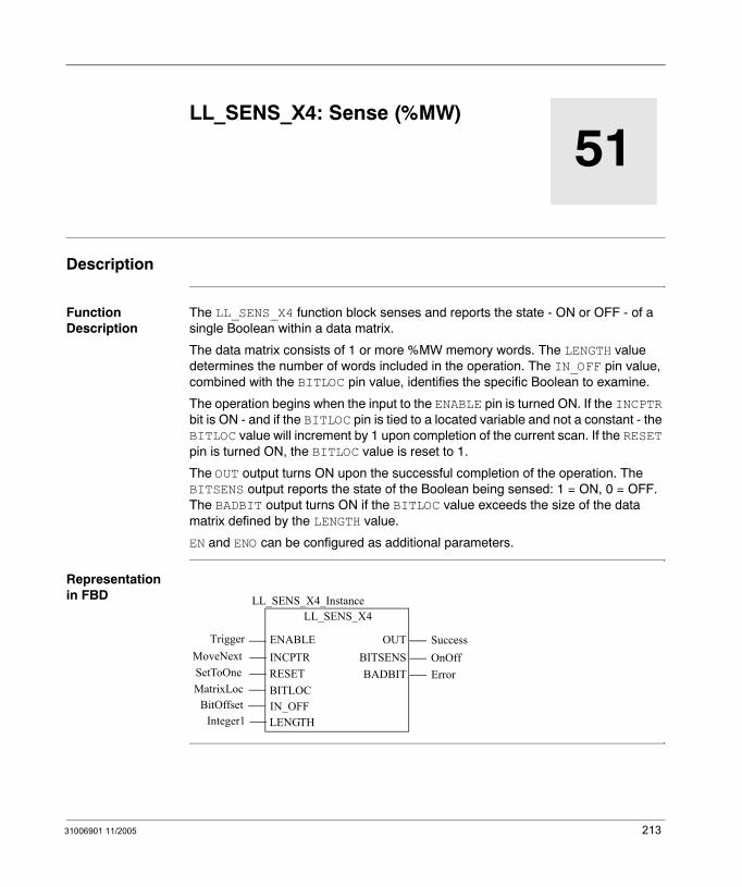
31006901 11/2005
51
LL_SENS_X4: Sense (%MW)Description
Function Description
The LL_SENS_X4 function block senses and reports the state - ON or OFF - of a single Boolean within a data matrix.
The data matrix consists of 1 or more %MW memory words. The LENGTH value determines the number of words included in the operation. The IN_OFF pin value, combined with the BITLOC pin value, identifies the specific Boolean to examine.
The operation begins when the input to the ENABLE pin is turned ON. If the INCPTR bit is ON - and if the BITLOC pin is tied to a located variable and not a constant - the BITLOC value will increment by 1 upon completion of the current scan. If the RESET pin is turned ON, the BITLOC value is reset to 1.
The OUT output turns ON upon the successful completion of the operation. The BITSENS output reports the state of the Boolean being sensed: 1 = ON, 0 = OFF. The BADBIT output turns ON if the BITLOC value exceeds the size of the data matrix defined by the LENGTH value.
EN and ENO can be configured as additional parameters.
Representation in FBD
LL_SENS_X4
Trigger
LL_SENS_X4_Instance
OUTENABLE
RESETBITLOC
SetToOneMatrixLoc
SuccessBITSENS OnOff
IN_OFFBitOffsetLENGTHInteger1
BADBIT ErrorINCPTRMoveNext
213
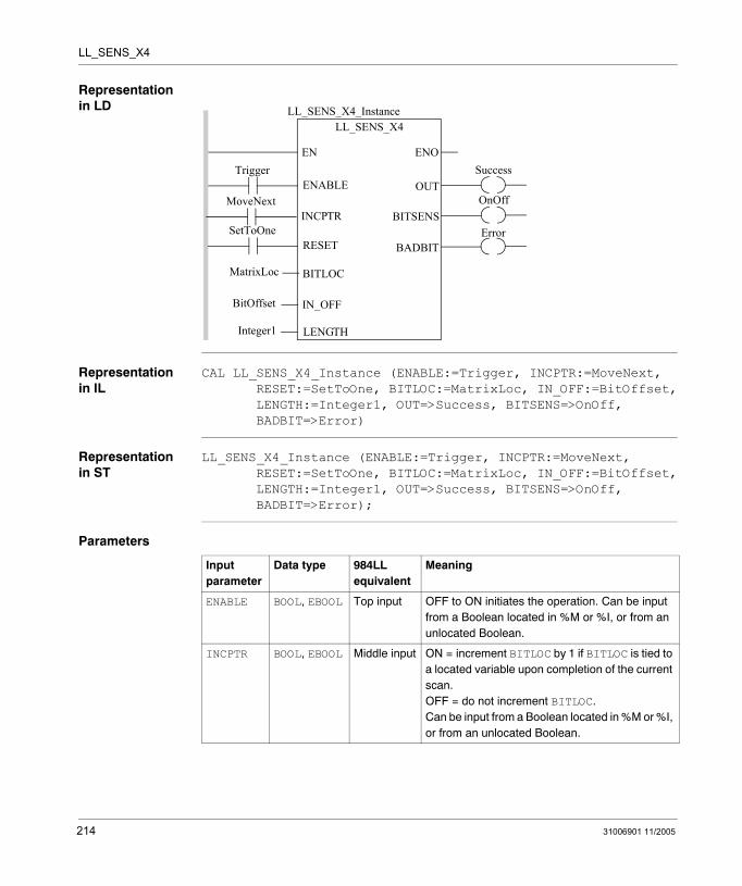
LL_SENS_X4
Representation in LD
Representation in IL
CAL LL_SENS_X4_Instance (ENABLE:=Trigger, INCPTR:=MoveNext,RESET:=SetToOne, BITLOC:=MatrixLoc, IN_OFF:=BitOffset,LENGTH:=Integer1, OUT=>Success, BITSENS=>OnOff, BADBIT=>Error)
Representation in ST
LL_SENS_X4_Instance (ENABLE:=Trigger, INCPTR:=MoveNext,RESET:=SetToOne, BITLOC:=MatrixLoc, IN_OFF:=BitOffset,LENGTH:=Integer1, OUT=>Success, BITSENS=>OnOff, BADBIT=>Error);
Parameters
Trigger
MatrixLoc
ENOENSuccess
LL_SENS_X4LL_SENS_X4_Instance
OUTENABLE
BITLOC
IN_OFF
LENGTH
BitOffset
Integer1
OnOffBITSENS
SetToOneRESET
MoveNextINCPTR
BADBITError
Input parameter
Data type 984LL equivalent
Meaning
ENABLE BOOL, EBOOL Top input OFF to ON initiates the operation. Can be input from a Boolean located in %M or %I, or from an unlocated Boolean.
INCPTR BOOL, EBOOL Middle input ON = increment BITLOC by 1 if BITLOC is tied to a located variable upon completion of the current scan.OFF = do not increment BITLOC.Can be input from a Boolean located in %M or %I, or from an unlocated Boolean.
214 31006901 11/2005
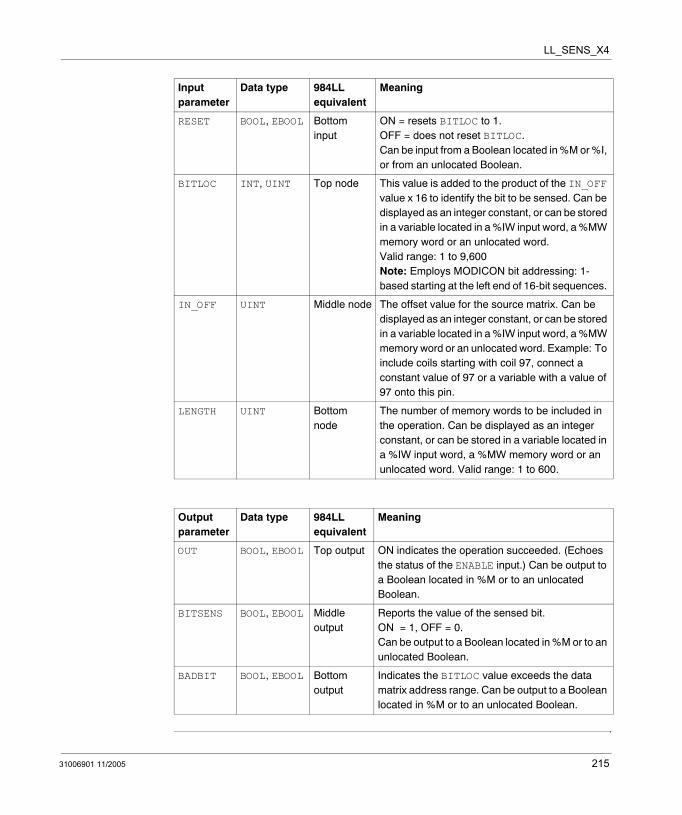
LL_SENS_X4
RESET BOOL, EBOOL Bottom input
ON = resets BITLOC to 1.OFF = does not reset BITLOC. Can be input from a Boolean located in %M or %I, or from an unlocated Boolean.
BITLOC INT, UINT Top node This value is added to the product of the IN_OFF value x 16 to identify the bit to be sensed. Can be displayed as an integer constant, or can be stored in a variable located in a %IW input word, a %MW memory word or an unlocated word. Valid range: 1 to 9,600Note: Employs MODICON bit addressing: 1-based starting at the left end of 16-bit sequences.
IN_OFF UINT Middle node The offset value for the source matrix. Can be displayed as an integer constant, or can be stored in a variable located in a %IW input word, a %MW memory word or an unlocated word. Example: To include coils starting with coil 97, connect a constant value of 97 or a variable with a value of 97 onto this pin.
LENGTH UINT Bottom node
The number of memory words to be included in the operation. Can be displayed as an integer constant, or can be stored in a variable located in a %IW input word, a %MW memory word or an unlocated word. Valid range: 1 to 600.
Output parameter
Data type 984LL equivalent
Meaning
OUT BOOL, EBOOL Top output ON indicates the operation succeeded. (Echoes the status of the ENABLE input.) Can be output to a Boolean located in %M or to an unlocated Boolean.
BITSENS BOOL, EBOOL Middle output
Reports the value of the sensed bit. ON = 1, OFF = 0. Can be output to a Boolean located in %M or to an unlocated Boolean.
BADBIT BOOL, EBOOL Bottom output
Indicates the BITLOC value exceeds the data matrix address range. Can be output to a Boolean located in %M or to an unlocated Boolean.
Input parameter
Data type 984LL equivalent
Meaning
31006901 11/2005 215

LL_SENS_X4
216 31006901 11/2005
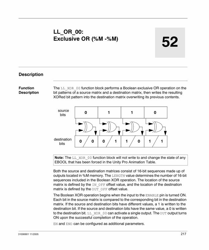
31006901 11/2005
52
LL_OR_00: Exclusive OR (%M -%M)Description
Function Description
The LL_XOR_00 function block performs a Boolean exclusive OR operation on the bit patterns of a source matrix and a destination matrix, then writes the resulting XORed bit pattern into the destination matrix overwriting its previous contents.
Both the source and destination matrices consist of 16-bit sequences made up of outputs located in %M memory. The LENGTH value determines the number of 16-bit sequences included in the Boolean XOR operation. The location of the source matrix is defined by the IN_OFF offset value, and the location of the destination matrix is defined by the OUT_OFF offset value.
The Boolean XOR operation begins when the input to the ENABLE pin is turned ON. Each bit in the source matrix is compared to the corresponding bit in the destination matrix. If the source and destination bits have different values, a 1 is written to the destination bit. If the source and destination bits have the same value, a 0 is written to the destination bit. LL_XOR_00 can activate a single output. The OUT output turns ON upon the successful completion of the operation.
EN and ENO can be configured as additional parameters.
Note: The LL_XOR_00 function block will not write to and change the state of any EBOOL that has been forced in the Unity Pro Animation Table.
0
0 0
1
0 1
sourcebits
destinationbits
1
1 0
0
1 1
217

LL_XOR_00
Representation in FBD
Representation in LD
Representation in IL
CAL LL_XOR_00_Instance (ENABLE:=Trigger, IN_OFF:=Source, OUT_OFF:=Destination, LENGTH:=Integer1, OUT=>Success
Representation in ST
LL_XOR_00_Instance (ENABLE:=Trigger, IN_OFF:=Source, OUT_OFF:=Destination, LENGTH:=Integer1, OUT=>Success;
Note: If you want to retain the original destination bit pattern, copy the information into another table using the LL_BLKM_00 block, before performing the LL_XOR_00 operation.
LL_XOR_00
TriggerSource
LL_XOR_00_Instance
OUTENABLEIN_OFFOUT_OFFLENGTH
DestinationInteger1
Success
Trigger
Source
ENOENSuccess
LL_XOR_00LL_XOR_00_Instance
OUTENABLE
IN_OFF
OUT_OFF
LENGTH
Destination
Integer1
218 31006901 11/2005
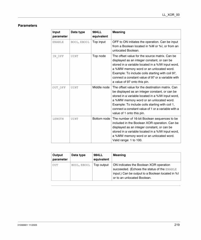
LL_XOR_00
Parameters
Input parameter
Data type 984LL equivalent
Meaning
ENABLE BOOL, EBOOL Top input OFF to ON initiates the operation. Can be input from a Boolean located in %M or %I, or from an unlocated Boolean.
IN_OFF UINT Top node The offset value for the source matrix. Can be displayed as an integer constant, or can be stored in a variable located in a %IW input word, a %MW memory word or an unlocated word. Example: To include coils starting with coil 97, connect a constant value of 97 or a variable with a value of 97 onto this pin.
OUT_OFF UINT Middle node The offset value for the destination matrix. Can be displayed as an integer constant, or can be stored in a variable located in a %IW input word, a %MW memory word or an unlocated word. Example: To include coils starting with coil 1, connect a constant value of 1 or a variable with a value of 1 onto this pin.
LENGTH UINT Bottom node The number of 16-bit Boolean sequences to be included in the Boolean XOR operation. Can be displayed as an integer constant, or can be stored in a variable located in a %IW input word, a %MW memory word or an unlocated word. Valid range: 1 to 100.
Output parameter
Data type 984LL equivalent
Meaning
OUT BOOL, EBOOL Top output ON indicates the Boolean XOR operation succeeded. (Echoes the status of the ENABLE input.) Can be output to a Boolean located in %I or to an unlocated Boolean.
31006901 11/2005 219

LL_XOR_00
220 31006901 11/2005

31006901 11/2005
53
LL_XOR_04: Exclusive OR (%M - %MW)Description
Function Description
The LL_XOR_04 function block performs a Boolean exclusive OR operation on the bit patterns of a source matrix and a destination matrix, then writes the resulting XORed bit pattern into the destination matrix overwriting its previous contents.
Both the source and destination matrices consist of 16-bit sequences. The source matrix consists of outputs located in %M memory; the destination matrix consists of words located in %MW memory. The LENGTH value determines the number of 16-bit sequences included in the Boolean XOR operation. The location of the source matrix is defined by the IN_OFF offset value, and the location of the destination matrix is defined by the OUT_OFF offset value.
The Boolean XOR operation begins when the input to the ENABLE pin is turned ON. Each bit in the source matrix is compared to the corresponding bit in the destination matrix. If the source and destination bits have different values, a 1 is written to the destination bit. If the source and destination bits have the same value, a 0 is written to the destination bit. LL_XOR_04 can activate a single output. The OUT output turns ON upon the successful completion of the operation.
EN and ENO can be configured as additional parameters.
Note: If you want to retain the original destination bit pattern, copy the information into another table using the LL_BLKM_04 block, before performing the LL_XOR_04 operation.
0
0 0
1
0 1
sourcebits
destinationbits
1
1 0
0
1 1
221

LL_XOR_04
Representation in FBD
Representation in LD
Representation in IL
CAL LL_XOR_04_Instance (ENABLE:=Trigger, IN_OFF:=Source, OUT_OFF:=Destination, LENGTH:=Integer1, OUT=>Success
Representation in ST
LL_XOR_04_Instance (ENABLE:=Trigger, IN_OFF:=Source, OUT_OFF:=Destination, LENGTH:=Integer1, OUT=>Success;
LL_XOR_04
TriggerSource
LL_XOR_04_Instance
OUTENABLEIN_OFFOUT_OFFLENGTH
DestinationInteger1
Success
Trigger
Source
ENOENSuccess
LL_XOR_04LL_XOR_04_Instance
OUTENABLE
IN_OFF
OUT_OFF
LENGTH
Destination
Integer1
222 31006901 11/2005
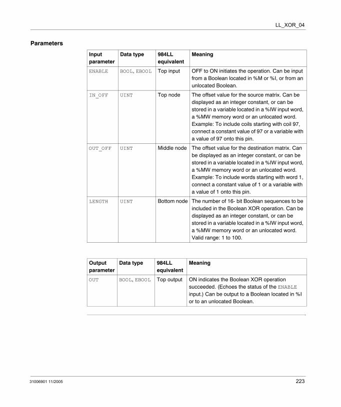
LL_XOR_04
Parameters
Input parameter
Data type 984LL equivalent
Meaning
ENABLE BOOL, EBOOL Top input OFF to ON initiates the operation. Can be input from a Boolean located in %M or %I, or from an unlocated Boolean.
IN_OFF UINT Top node The offset value for the source matrix. Can be displayed as an integer constant, or can be stored in a variable located in a %IW input word, a %MW memory word or an unlocated word. Example: To include coils starting with coil 97, connect a constant value of 97 or a variable with a value of 97 onto this pin.
OUT_OFF UINT Middle node The offset value for the destination matrix. Can be displayed as an integer constant, or can be stored in a variable located in a %IW input word, a %MW memory word or an unlocated word. Example: To include words starting with word 1, connect a constant value of 1 or a variable with a value of 1 onto this pin.
LENGTH UINT Bottom node The number of 16- bit Boolean sequences to be included in the Boolean XOR operation. Can be displayed as an integer constant, or can be stored in a variable located in a %IW input word, a %MW memory word or an unlocated word. Valid range: 1 to 100.
Output parameter
Data type 984LL equivalent
Meaning
OUT BOOL, EBOOL Top output ON indicates the Boolean XOR operation succeeded. (Echoes the status of the ENABLE input.) Can be output to a Boolean located in %I or to an unlocated Boolean.
31006901 11/2005 223

LL_XOR_04
224 31006901 11/2005
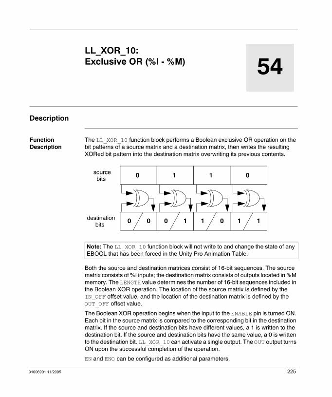
31006901 11/2005
54
LL_XOR_10: Exclusive OR (%I - %M)Description
Function Description
The LL_XOR_10 function block performs a Boolean exclusive OR operation on the bit patterns of a source matrix and a destination matrix, then writes the resulting XORed bit pattern into the destination matrix overwriting its previous contents.
Both the source and destination matrices consist of 16-bit sequences. The source matrix consists of %I inputs; the destination matrix consists of outputs located in %M memory. The LENGTH value determines the number of 16-bit sequences included in the Boolean XOR operation. The location of the source matrix is defined by the IN_OFF offset value, and the location of the destination matrix is defined by the OUT_OFF offset value.
The Boolean XOR operation begins when the input to the ENABLE pin is turned ON. Each bit in the source matrix is compared to the corresponding bit in the destination matrix. If the source and destination bits have different values, a 1 is written to the destination bit. If the source and destination bits have the same value, a 0 is written to the destination bit. LL_XOR_10 can activate a single output. The OUT output turns ON upon the successful completion of the operation.
EN and ENO can be configured as additional parameters.
Note: The LL_XOR_10 function block will not write to and change the state of any EBOOL that has been forced in the Unity Pro Animation Table.
0
0 0
1
0 1
sourcebits
destinationbits
1
1 0
0
1 1
225
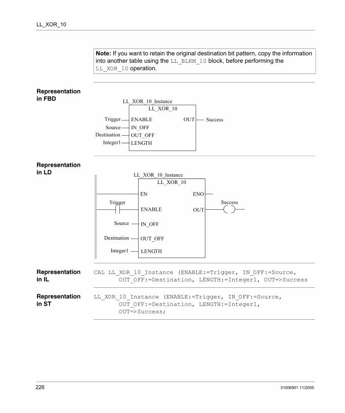
LL_XOR_10
Representation in FBD
Representation in LD
Representation in IL
CAL LL_XOR_10_Instance (ENABLE:=Trigger, IN_OFF:=Source, OUT_OFF:=Destination, LENGTH:=Integer1, OUT=>Success
Representation in ST
LL_XOR_10_Instance (ENABLE:=Trigger, IN_OFF:=Source, OUT_OFF:=Destination, LENGTH:=Integer1, OUT=>Success;
Note: If you want to retain the original destination bit pattern, copy the information into another table using the LL_BLKM_10 block, before performing the LL_XOR_10 operation.
LL_XOR_10
TriggerSource
LL_XOR_10_Instance
OUTENABLEIN_OFFOUT_OFFLENGTH
DestinationInteger1
Success
Trigger
Source
ENOENSuccess
LL_XOR_10LL_XOR_10_Instance
OUTENABLE
IN_OFF
OUT_OFF
LENGTH
Destination
Integer1
226 31006901 11/2005
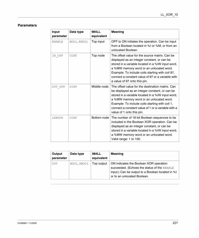
LL_XOR_10
Parameters
Input parameter
Data type 984LL equivalent
Meaning
ENABLE BOOL, EBOOL Top input OFF to ON initiates the operation. Can be input from a Boolean located in %I or %M, or from an unlocated Boolean.
IN_OFF UINT Top node The offset value for the source matrix. Can be displayed as an integer constant, or can be stored in a variable located in a %IW input word, a %MW memory word or an unlocated word. Example: To include coils starting with coil 97, connect a constant value of 97 or a variable with a value of 97 onto this pin.
OUT_OFF UINT Middle node The offset value for the destination matrix. Can be displayed as an integer constant, or can be stored in a variable located in a %IW input word, a %MW memory word or an unlocated word. Example: To include coils starting with coil 1, connect a constant value of 1 or a variable with a value of 1 onto this pin.
LENGTH UINT Bottom node The number of 16-bit Boolean sequences to be included in the Boolean XOR operation. Can be displayed as an integer constant, or can be stored in a variable located in a %IW input word, a %MW memory word or an unlocated word. Valid range: 1 to 100.
Output parameter
Data type 984LL equivalent
Meaning
OUT BOOL, EBOOL Top output ON indicates the Boolean XOR operation succeeded. (Echoes the status of the ENABLE input.) Can be output to a Boolean located in %I or to an unlocated Boolean.
31006901 11/2005 227

LL_XOR_10
228 31006901 11/2005
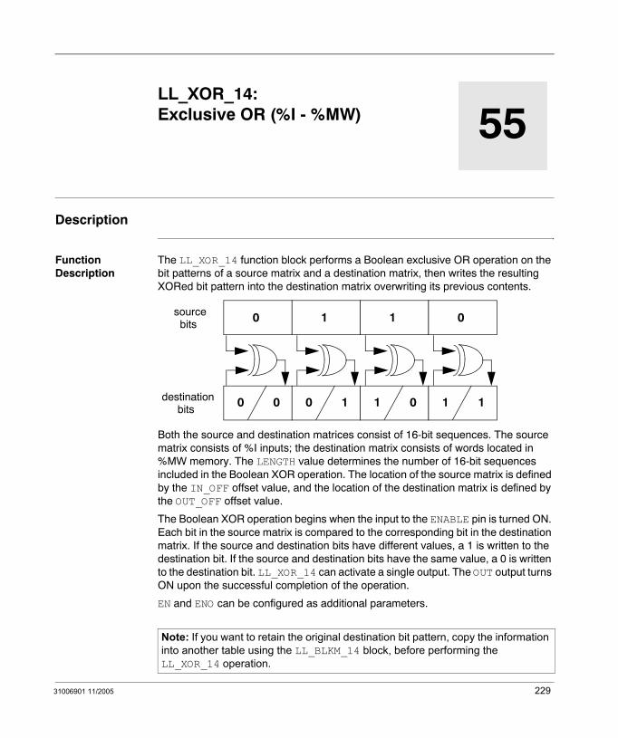
31006901 11/2005
55
LL_XOR_14: Exclusive OR (%I - %MW)Description
Function Description
The LL_XOR_14 function block performs a Boolean exclusive OR operation on the bit patterns of a source matrix and a destination matrix, then writes the resulting XORed bit pattern into the destination matrix overwriting its previous contents.
Both the source and destination matrices consist of 16-bit sequences. The source matrix consists of %I inputs; the destination matrix consists of words located in %MW memory. The LENGTH value determines the number of 16-bit sequences included in the Boolean XOR operation. The location of the source matrix is defined by the IN_OFF offset value, and the location of the destination matrix is defined by the OUT_OFF offset value.
The Boolean XOR operation begins when the input to the ENABLE pin is turned ON. Each bit in the source matrix is compared to the corresponding bit in the destination matrix. If the source and destination bits have different values, a 1 is written to the destination bit. If the source and destination bits have the same value, a 0 is written to the destination bit. LL_XOR_14 can activate a single output. The OUT output turns ON upon the successful completion of the operation.
EN and ENO can be configured as additional parameters.
Note: If you want to retain the original destination bit pattern, copy the information into another table using the LL_BLKM_14 block, before performing the LL_XOR_14 operation.
0
0 0
1
0 1
sourcebits
destinationbits
1
1 0
0
1 1
229

LL_XOR_14
Representation in FBD
Representation in LD
Representation in IL
CAL LL_XOR_14_Instance (ENABLE:=Trigger, IN_OFF:=Source, OUT_OFF:=Destination, LENGTH:=Integer1, OUT=>Success
Representation in ST
LL_XOR_14_Instance (ENABLE:=Trigger, IN_OFF:=Source, OUT_OFF:=Destination, LENGTH:=Integer1, OUT=>Success;
LL_XOR_14
TriggerSource
LL_XOR_14_Instance
OUTENABLEIN_OFFOUT_OFFLENGTH
DestinationInteger1
Success
Trigger
Source
ENOENSuccess
LL_XOR_14LL_XOR_14_Instance
OUTENABLE
IN_OFF
OUT_OFF
LENGTH
Destination
Integer1
230 31006901 11/2005

LL_XOR_14
Parameters
Input parameter
Data type 984LL equivalent
Meaning
ENABLE BOOL, EBOOL Top input OFF to ON initiates the operation. Can be input from a Boolean located in %M or %I, or from an unlocated Boolean.
IN_OFF UINT Top node The offset value for the source matrix. Can be displayed as an integer constant, or can be stored in a variable located in a %IW input word, a %MW memory word or an unlocated word. Example: To include coils starting with coil 97, connect a constant value of 97 or a variable with a value of 97 onto this pin.
OUT_OFF UINT Middle node The offset value for the destination matrix. Can be displayed as an integer constant, or can be stored in a variable located in a %IW input word, a %MW memory word or an unlocated word. Example: To include words starting with word 1, connect a constant value of 1 or a variable with a value of 1 onto this pin.
LENGTH UINT Bottom node The number of 16-bit Boolean sequences to be included in the Boolean XOR operation. Can be displayed as an integer constant, or can be stored in a variable located in a %IW input word, a %MW memory word or an unlocated word. Valid range: 1 to 100.
Output parameter
Data type 984LL equivalent
Meaning
OUT BOOL, EBOOL Top output ON indicates the Boolean XOR operation succeeded. (Echoes the status of the ENABLE input.) Can be output to a Boolean located in %I or to an unlocated Boolean.
31006901 11/2005 231

LL_XOR_14
232 31006901 11/2005

31006901 11/2005
56
LL_XOR_30: Exclusive OR (%IW - %M)Description
Function Description
The LL_XOR_30 function block performs a Boolean exclusive OR operation on the bit patterns of a source matrix and a destination matrix, then writes the resulting XORed bit pattern into the destination matrix overwriting its previous contents.
Both the source and destination matrices consist of 16-bit sequences. The source matrix consists of %IW input words; the destination matrix consists of outputs located in %M memory. The LENGTH value determines the number of 16-bit sequences included in the Boolean XOR operation. The location of the source matrix is defined by the IN_OFF offset value, and the location of the destination matrix is defined by the OUT_OFF offset value.
The Boolean XOR operation begins when the input to the ENABLE pin is turned ON. Each bit in the source matrix is compared to the corresponding bit in the destination matrix. If the source and destination bits have different values, a 1 is written to the destination bit. If the source and destination bits have the same value, a 0 is written to the destination bit. LL_XOR_30 can activate a single output. The OUT output turns ON upon the successful completion of the operation.
EN and ENO can be configured as additional parameters.
Note: The LL_XOR_30 function block will not write to and change the state of any EBOOL that has been forced in the Unity Pro Animation Table.
0
0 0
1
0 1
sourcebits
destinationbits
1
1 0
0
1 1
233

LL_XOR_30
Representation in FBD
Representation in LD
Representation in IL
CAL LL_XOR_30_Instance (ENABLE:=Trigger, IN_OFF:=Source, OUT_OFF:=Destination, LENGTH:=Integer1, OUT=>Success
Representation in ST
LL_XOR_30_Instance (ENABLE:=Trigger, IN_OFF:=Source, OUT_OFF:=Destination, LENGTH:=Integer1, OUT=>Success;
Note: If you want to retain the original destination bit pattern, copy the information into another table using the LL_BLKM_30 block, before performing the LL_XOR_30 operation.
LL_XOR_30
TriggerSource
LL_XOR_30_Instance
OUTENABLEIN_OFFOUT_OFFLENGTH
DestinationInteger1
Success
Trigger
Source
ENOENSuccess
LL_XOR_30LL_XOR_30_Instance
OUTENABLE
IN_OFF
OUT_OFF
LENGTH
Destination
Integer1
234 31006901 11/2005

LL_XOR_30
Parameters
Input parameter
Data type 984LL equivalent
Meaning
ENABLE BOOL, EBOOL Top input OFF to ON initiates the operation. Can be input from a Boolean located in %I or %M, or from an unlocated Boolean.
IN_OFF UINT Top node The offset value for the source matrix. Can be displayed as an integer constant, or can be stored in a variable located in a $IW input word, a %MW memory word or an unlocated word. Example: To include words starting with word 97, connect a constant value of 97 or a variable with a value of 97 onto this pin.
OUT_OFF UINT Middle node The offset value for the destination matrix. Can be displayed as an integer constant, or can be stored in a variable located in a %IW input word, a %MW memory word or an unlocated word. Example: To include coils starting with coil 1, connect a constant value of 1 or a variable with a value of 1 onto this pin.
LENGTH UINT Bottom node The number of 16-bit Boolean sequences to be included in the Boolean XOR operation. Can be displayed as an integer constant, or can be stored in a variable located in a %IW input word, a %MW memory word or an unlocated word. Valid range: 1 to 100.
Output parameter
Data type 984LL equivalent
Meaning
OUT BOOL, EBOOL Top output ON indicates the Boolean XOR operation succeeded. (Echoes the status of the ENABLE input.) Can be output to a Boolean located in %I or to an unlocated Boolean.
31006901 11/2005 235

LL_XOR_30
236 31006901 11/2005
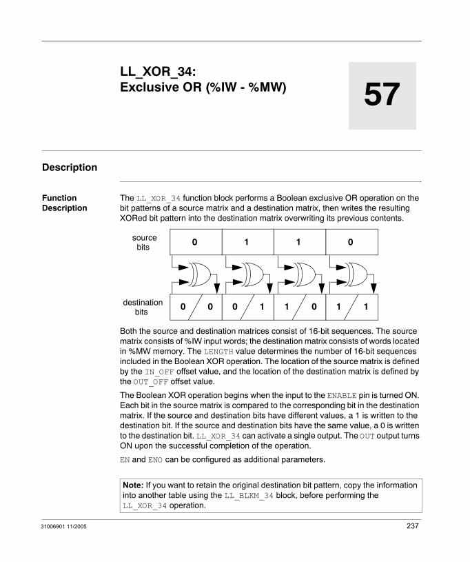
31006901 11/2005
57
LL_XOR_34: Exclusive OR (%IW - %MW)Description
Function Description
The LL_XOR_34 function block performs a Boolean exclusive OR operation on the bit patterns of a source matrix and a destination matrix, then writes the resulting XORed bit pattern into the destination matrix overwriting its previous contents.
Both the source and destination matrices consist of 16-bit sequences. The source matrix consists of %IW input words; the destination matrix consists of words located in %MW memory. The LENGTH value determines the number of 16-bit sequences included in the Boolean XOR operation. The location of the source matrix is defined by the IN_OFF offset value, and the location of the destination matrix is defined by the OUT_OFF offset value.
The Boolean XOR operation begins when the input to the ENABLE pin is turned ON. Each bit in the source matrix is compared to the corresponding bit in the destination matrix. If the source and destination bits have different values, a 1 is written to the destination bit. If the source and destination bits have the same value, a 0 is written to the destination bit. LL_XOR_34 can activate a single output. The OUT output turns ON upon the successful completion of the operation.
EN and ENO can be configured as additional parameters.
Note: If you want to retain the original destination bit pattern, copy the information into another table using the LL_BLKM_34 block, before performing the LL_XOR_34 operation.
0
0 0
1
0 1
sourcebits
destinationbits
1
1 0
0
1 1
237

LL_XOR_34
Representation in FBD
Representation in LD
Representation in IL
CAL LL_XOR_34_Instance (ENABLE:=Trigger, IN_OFF:=Source, OUT_OFF:=Destination, LENGTH:=Integer1, OUT=>Success
Representation in ST
LL_XOR_34_Instance (ENABLE:=Trigger, IN_OFF:=Source, OUT_OFF:=Destination, LENGTH:=Integer1, OUT=>Success;
LL_XOR_34
TriggerSource
LL_XOR_34_Instance
OUTENABLEIN_OFFOUT_OFFLENGTH
DestinationInteger1
Success
Trigger
Source
ENOENSuccess
LL_XOR_34LL_XOR_34_Instance
OUTENABLE
IN_OFF
OUT_OFF
LENGTH
Destination
Integer1
238 31006901 11/2005
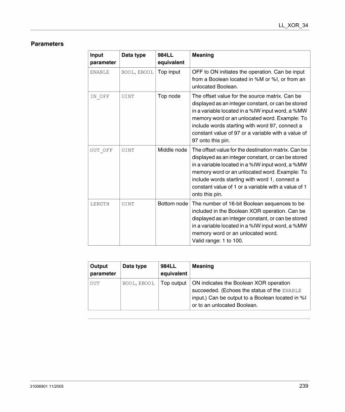
LL_XOR_34
Parameters
Input parameter
Data type 984LL equivalent
Meaning
ENABLE BOOL, EBOOL Top input OFF to ON initiates the operation. Can be input from a Boolean located in %M or %I, or from an unlocated Boolean.
IN_OFF UINT Top node The offset value for the source matrix. Can be displayed as an integer constant, or can be stored in a variable located in a %IW input word, a %MW memory word or an unlocated word. Example: To include words starting with word 97, connect a constant value of 97 or a variable with a value of 97 onto this pin.
OUT_OFF UINT Middle node The offset value for the destination matrix. Can be displayed as an integer constant, or can be stored in a variable located in a %IW input word, a %MW memory word or an unlocated word. Example: To include words starting with word 1, connect a constant value of 1 or a variable with a value of 1 onto this pin.
LENGTH UINT Bottom node The number of 16-bit Boolean sequences to be included in the Boolean XOR operation. Can be displayed as an integer constant, or can be stored in a variable located in a %IW input word, a %MW memory word or an unlocated word. Valid range: 1 to 100.
Output parameter
Data type 984LL equivalent
Meaning
OUT BOOL, EBOOL Top output ON indicates the Boolean XOR operation succeeded. (Echoes the status of the ENABLE input.) Can be output to a Boolean located in %I or to an unlocated Boolean.
31006901 11/2005 239

LL_XOR_34
240 31006901 11/2005
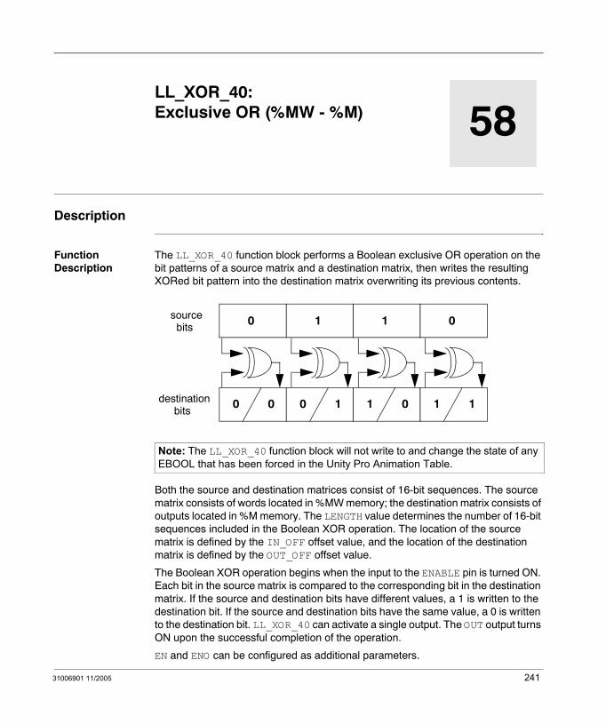
31006901 11/2005
58
LL_XOR_40: Exclusive OR (%MW - %M)Description
Function Description
The LL_XOR_40 function block performs a Boolean exclusive OR operation on the bit patterns of a source matrix and a destination matrix, then writes the resulting XORed bit pattern into the destination matrix overwriting its previous contents.
Both the source and destination matrices consist of 16-bit sequences. The source matrix consists of words located in %MW memory; the destination matrix consists of outputs located in %M memory. The LENGTH value determines the number of 16-bit sequences included in the Boolean XOR operation. The location of the source matrix is defined by the IN_OFF offset value, and the location of the destination matrix is defined by the OUT_OFF offset value.
The Boolean XOR operation begins when the input to the ENABLE pin is turned ON. Each bit in the source matrix is compared to the corresponding bit in the destination matrix. If the source and destination bits have different values, a 1 is written to the destination bit. If the source and destination bits have the same value, a 0 is written to the destination bit. LL_XOR_40 can activate a single output. The OUT output turns ON upon the successful completion of the operation.
EN and ENO can be configured as additional parameters.
Note: The LL_XOR_40 function block will not write to and change the state of any EBOOL that has been forced in the Unity Pro Animation Table.
0
0 0
1
0 1
sourcebits
destinationbits
1
1 0
0
1 1
241

LL_XOR_40
Representation in FBD
Representation in LD
Representation in IL
CAL LL_XOR_40_Instance (ENABLE:=Trigger, IN_OFF:=Source, OUT_OFF:=Destination, LENGTH:=Integer1, OUT=>Success
Representation in ST
LL_XOR_40_Instance (ENABLE:=Trigger, IN_OFF:=Source, OUT_OFF:=Destination, LENGTH:=Integer1, OUT=>Success;
Note: If you want to retain the original destination bit pattern, copy the information into another table using the LL_BLKM_40 block, before performing the LL_XOR_40 operation.
LL_XOR_40
TriggerSource
LL_XOR_40_Instance
OUTENABLEIN_OFFOUT_OFFLENGTH
DestinationInteger1
Success
Trigger
Source
ENOENSuccess
LL_XOR_40LL_XOR_40_Instance
OUTENABLE
IN_OFF
OUT_OFF
LENGTH
Destination
Integer1
242 31006901 11/2005
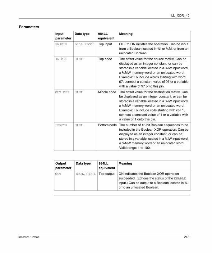
LL_XOR_40
Parameters
Input parameter
Data type 984LL equivalent
Meaning
ENABLE BOOL, EBOOL Top input OFF to ON initiates the operation. Can be input from a Boolean located in %I or %M, or from an unlocated Boolean.
IN_OFF UINT Top node The offset value for the source matrix. Can be displayed as an integer constant, or can be stored in a variable located in a %IW input word, a %MW memory word or an unlocated word. Example: To include words starting with word 97, connect a constant value of 97 or a variable with a value of 97 onto this pin.
OUT_OFF UINT Middle node The offset value for the destination matrix. Can be displayed as an integer constant, or can be stored in a variable located in a %IW input word, a %MW memory word or an unlocated word. Example: To include coils starting with coil 1, connect a constant value of 1 or a variable with a value of 1 onto this pin.
LENGTH UINT Bottom node The number of 16-bit Boolean sequences to be included in the Boolean XOR operation. Can be displayed as an integer constant, or can be stored in a variable located in a %IW input word, a %MW memory word or an unlocated word. Valid range: 1 to 100.
Output parameter
Data type 984LL equivalent
Meaning
OUT BOOL, EBOOL Top output ON indicates the Boolean XOR operation succeeded. (Echoes the status of the ENABLE input.) Can be output to a Boolean located in %I or to an unlocated Boolean.
31006901 11/2005 243

LL_XOR_40
244 31006901 11/2005
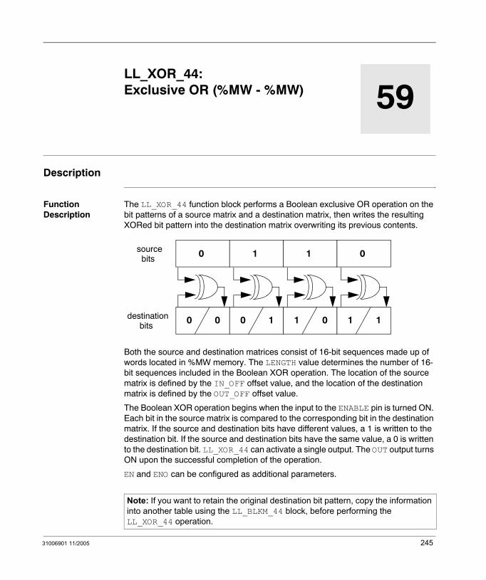
31006901 11/2005
59
LL_XOR_44: Exclusive OR (%MW - %MW)Description
Function Description
The LL_XOR_44 function block performs a Boolean exclusive OR operation on the bit patterns of a source matrix and a destination matrix, then writes the resulting XORed bit pattern into the destination matrix overwriting its previous contents.
Both the source and destination matrices consist of 16-bit sequences made up of words located in %MW memory. The LENGTH value determines the number of 16-bit sequences included in the Boolean XOR operation. The location of the source matrix is defined by the IN_OFF offset value, and the location of the destination matrix is defined by the OUT_OFF offset value.
The Boolean XOR operation begins when the input to the ENABLE pin is turned ON. Each bit in the source matrix is compared to the corresponding bit in the destination matrix. If the source and destination bits have different values, a 1 is written to the destination bit. If the source and destination bits have the same value, a 0 is written to the destination bit. LL_XOR_44 can activate a single output. The OUT output turns ON upon the successful completion of the operation.
EN and ENO can be configured as additional parameters.
Note: If you want to retain the original destination bit pattern, copy the information into another table using the LL_BLKM_44 block, before performing the LL_XOR_44 operation.
0
0 0
1
0 1
sourcebits
destinationbits
1
1 0
0
1 1
245
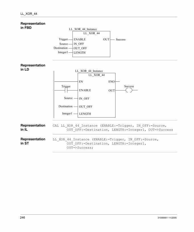
LL_XOR_44
Representation in FBD
Representation in LD
Representation in IL
CAL LL_XOR_44_Instance (ENABLE:=Trigger, IN_OFF:=Source, OUT_OFF:=Destination, LENGTH:=Integer1, OUT=>Success
Representation in ST
LL_XOR_44_Instance (ENABLE:=Trigger, IN_OFF:=Source, OUT_OFF:=Destination, LENGTH:=Integer1, OUT=>Success;
LL_XOR_44
TriggerSource
LL_XOR_44_Instance
OUTENABLEIN_OFFOUT_OFFLENGTH
DestinationInteger1
Success
Trigger
Source
ENOENSuccess
LL_XOR_44LL_XOR_44_Instance
OUTENABLE
IN_OFF
OUT_OFF
LENGTH
Destination
Integer1
246 31006901 11/2005
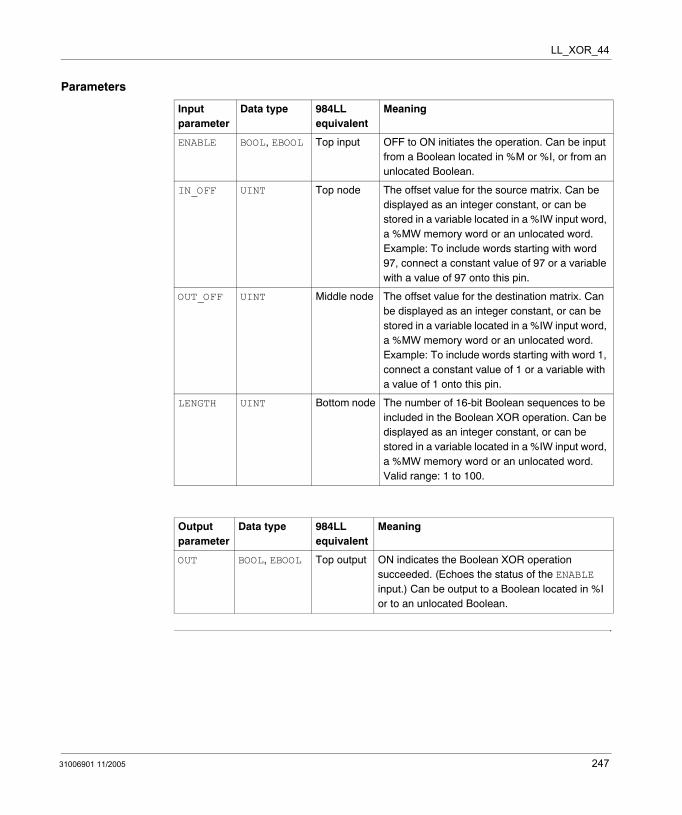
LL_XOR_44
Parameters
Input parameter
Data type 984LL equivalent
Meaning
ENABLE BOOL, EBOOL Top input OFF to ON initiates the operation. Can be input from a Boolean located in %M or %I, or from an unlocated Boolean.
IN_OFF UINT Top node The offset value for the source matrix. Can be displayed as an integer constant, or can be stored in a variable located in a %IW input word, a %MW memory word or an unlocated word. Example: To include words starting with word 97, connect a constant value of 97 or a variable with a value of 97 onto this pin.
OUT_OFF UINT Middle node The offset value for the destination matrix. Can be displayed as an integer constant, or can be stored in a variable located in a %IW input word, a %MW memory word or an unlocated word. Example: To include words starting with word 1, connect a constant value of 1 or a variable with a value of 1 onto this pin.
LENGTH UINT Bottom node The number of 16-bit Boolean sequences to be included in the Boolean XOR operation. Can be displayed as an integer constant, or can be stored in a variable located in a %IW input word, a %MW memory word or an unlocated word. Valid range: 1 to 100.
Output parameter
Data type 984LL equivalent
Meaning
OUT BOOL, EBOOL Top output ON indicates the Boolean XOR operation succeeded. (Echoes the status of the ENABLE input.) Can be output to a Boolean located in %I or to an unlocated Boolean.
31006901 11/2005 247

LL_XOR_44
248 31006901 11/2005
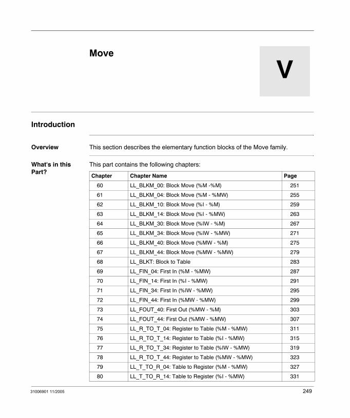
31006901 11/2005
V
MoveIntroduction
Overview This section describes the elementary function blocks of the Move family.
What's in this Part?
This part contains the following chapters:
Chapter Chapter Name Page
60 LL_BLKM_00: Block Move (%M -%M) 251
61 LL_BLKM_04: Block Move (%M - %MW) 255
62 LL_BLKM_10: Block Move (%I - %M) 259
63 LL_BLKM_14: Block Move (%I - %MW) 263
64 LL_BLKM_30: Block Move (%IW - %M) 267
65 LL_BLKM_34: Block Move (%IW - %MW) 271
66 LL_BLKM_40: Block Move (%MW - %M) 275
67 LL_BLKM_44: Block Move (%MW - %MW) 279
68 LL_BLKT: Block to Table 283
69 LL_FIN_04: First In (%M - %MW) 287
70 LL_FIN_14: First In (%I - %MW) 291
71 LL_FIN_34: First In (%IW - %MW) 295
72 LL_FIN_44: First In (%MW - %MW) 299
73 LL_FOUT_40: First Out (%MW - %M) 303
74 LL_FOUT_44: First Out (%MW - %MW) 307
75 LL_R_TO_T_04: Register to Table (%M - %MW) 311
76 LL_R_TO_T_14: Register to Table (%I - %MW) 315
77 LL_R_TO_T_34: Register to Table (%IW - %MW) 319
78 LL_R_TO_T_44: Register to Table (%MW - %MW) 323
79 LL_T_TO_R_04: Table to Register (%M - %MW) 327
80 LL_T_TO_R_14: Table to Register (%I - %MW) 331
249
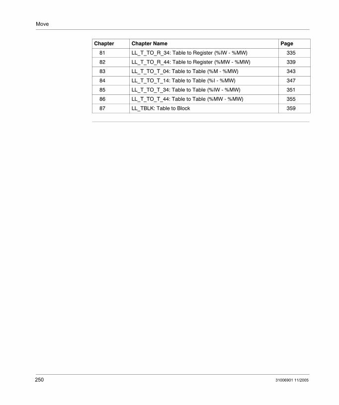
Move
81 LL_T_TO_R_34: Table to Register (%IW - %MW) 335
82 LL_T_TO_R_44: Table to Register (%MW - %MW) 339
83 LL_T_TO_T_04: Table to Table (%M - %MW) 343
84 LL_T_TO_T_14: Table to Table (%I - %MW) 347
85 LL_T_TO_T_34: Table to Table (%IW - %MW) 351
86 LL_T_TO_T_44: Table to Table (%MW - %MW) 355
87 LL_TBLK: Table to Block 359
Chapter Chapter Name Page
250 31006901 11/2005
31006901 11/2005
60
LL_BLKM_00: Block Move (%M -%M)Description
Function Description
The LL_BLKM_00 block move function block copies the entire contents of a source table to a destination table in 1 scan.
Both the source and destination tables consist of 16-bit sequences made up of outputs located in %M memory. The LENGTH value determines the number of 16-bit sequences included in the block move operation. The IN_OFF offset value defines the location of the source table. The OUT_OFF offset value defines the location of the destination table.
The block move operation begins when the input to the ENABLE pin is turned ON. LL_BLKM_00 can activate a single output. The OUT output turns ON upon the successful completion of the operation.
EN and ENO can be configured as additional parameters.
Note: The LL_BLKM_00 function block will not write to and change the state of any EBOOL that has been forced in the Unity Pro Animation Table.
251

LL_BLKM_00
Representation in FBD
Representation in LD
Representation in IL
CAL LL_BLKM_00_Instance (ENABLE:=Trigger, IN_OFF:=Source, OUT_OFF:=Destination, LENGTH:=Integer1, OUT=>Success
Representation in ST
LL_BLKM_00_Instance (ENABLE:=Trigger, IN_OFF:=Source, OUT_OFF:=Destination, LENGTH:=Integer1, OUT=>Success;
LL_BLKM_00
TriggerSource
LL_BLKM_00_Instance
OUTENABLEIN_OFFOUT_OFFLENGTH
DestinationInteger1
Success
Trigger
Source
ENOENSuccess
LL_BLKM_00LL_BLKM_00_Instance
OUTENABLE
IN_OFF
OUT_OFF
LENGTH
Destination
Integer1
252 31006901 11/2005

LL_BLKM_00
Parameters
Input parameter
Data type 984LL equivalent
Meaning
ENABLE BOOL, EBOOL Top input OFF to ON initiates the operation. Can be input from a Boolean located in %M or %I, or from an unlocated Boolean.
IN_OFF UINT Top node The offset value for the source table. Can be displayed as an integer constant, or can be stored in a variable located in a %IW input word, a %MW memory word or an unlocated word. Example: To include coils starting with coil 97, connect a constant value of 97 or a variable with a value of 97 onto this pin.
OUT_OFF UINT Middle node The offset value for the destination table. Can be displayed as an integer constant, or can be stored in a variable located in a %IW input word, a %MW memory word or an unlocated word. Example: To include coils starting with coil 1, connect a constant value of 1 or a variable with a value of 1 onto this pin.
LENGTH UINT Bottom node The number of 16-bit Boolean sequences to be included in the operation. Can be displayed as an integer constant, or can be stored in a variable located in a %IW input word, a %MW memory word or an unlocated word. Valid range: 1 to 100.
Output parameter
Data type 984LL equivalent
Meaning
OUT BOOL, EBOOL Top output ON indicates the operation succeeded. (Echoes the status of the ENABLE input.) Can be output to a Boolean located in %I or to an unlocated Boolean.
31006901 11/2005 253

LL_BLKM_00
254 31006901 11/2005
31006901 11/2005
61
LL_BLKM_04: Block Move (%M - %MW)Description
Function Description
The LL_BLKM_04 block move function block copies the entire contents of a source table to a destination table in 1 scan.
Both the source and destination tables consist of 16-bit sequences. The source table consists of outputs located in %M memory; the destination table consists of words located in %MW memory. The LENGTH value determines the number of 16-bit sequences included in the block move operation. The IN_OFF offset value defines the location of the source table. The OUT_OFF offset value defines the location of the destination table.
The block move operation begins when the input to the ENABLE pin is turned ON. LL_BLKM_04 can activate a single output. The OUT output turns ON upon the successful completion of the operation.
EN and ENO can be configured as additional parameters.
255

LL_BLKM_04
Representation in FBD
Representation in LD
Representation in IL
CAL LL_BLKM_04_Instance (ENABLE:=Trigger, IN_OFF:=Source, OUT_OFF:=Destination, LENGTH:=Integer1, OUT=>Success
Representation in ST
LL_BLKM_04_Instance (ENABLE:=Trigger, IN_OFF:=Source, OUT_OFF:=Destination, LENGTH:=Integer1, OUT=>Success;
LL_BLKM_04
TriggerSource
LL_BLKM_04_Instance
OUTENABLEIN_OFFOUT_OFFLENGTH
DestinationInteger1
Success
Trigger
Source
ENOENSuccess
LL_BLKM_04LL_BLKM_04_Instance
OUTENABLE
IN_OFF
OUT_OFF
LENGTH
Destination
Integer1
256 31006901 11/2005
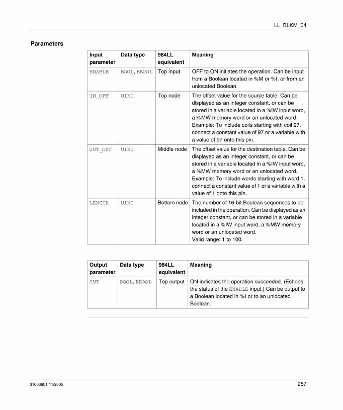
LL_BLKM_04
Parameters
Input parameter
Data type 984LL equivalent
Meaning
ENABLE BOOL, EBOOL Top input OFF to ON initiates the operation. Can be input from a Boolean located in %M or %I, or from an unlocated Boolean.
IN_OFF UINT Top node The offset value for the source table. Can be displayed as an integer constant, or can be stored in a variable located in a %IW input word, a %MW memory word or an unlocated word. Example: To include coils starting with coil 97, connect a constant value of 97 or a variable with a value of 97 onto this pin.
OUT_OFF UINT Middle node The offset value for the destination table. Can be displayed as an integer constant, or can be stored in a variable located in a %IW input word, a %MW memory word or an unlocated word. Example: To include words starting with word 1, connect a constant value of 1 or a variable with a value of 1 onto this pin.
LENGTH UINT Bottom node The number of 16-bit Boolean sequences to be included in the operation. Can be displayed as an integer constant, or can be stored in a variable located in a %IW input word, a %MW memory word or an unlocated word. Valid range: 1 to 100.
Output parameter
Data type 984LL equivalent
Meaning
OUT BOOL, EBOOL Top output ON indicates the operation succeeded. (Echoes the status of the ENABLE input.) Can be output to a Boolean located in %I or to an unlocated Boolean.
31006901 11/2005 257

LL_BLKM_04
258 31006901 11/2005
31006901 11/2005
62
LL_BLKM_10: Block Move (%I - %M)Description
Function Description
The LL_BLKM_10 block move function block copies the entire contents of a source table to a destination table in 1 scan.
Both the source and destination tables consist of 16-bit sequences. The source table consists of %I inputs; the destination table consists of outputs located in %M memory. The LENGTH value determines the number of 16-bit sequences included in the block move operation. The IN_OFF offset value defines the location of the source table. The OUT_OFF offset value defines the location of the destination table.
The block move operation begins when the input to the ENABLE pin is turned ON. LL_BLKM_10 can activate a single output. The OUT output turns ON upon the successful completion of the operation.
EN and ENO can be configured as additional parameters.
Note: The LL_BLKM_10 function block will not write to and change the state of any EBOOL that has been forced in the Unity Pro Animation Table.
259

LL_BLKM_10
Representation in FBD
Representation in LD
Representation in IL
CAL LL_BLKM_10_Instance (ENABLE:=Trigger, IN_OFF:=Source, OUT_OFF:=Destination, LENGTH:=Integer1, OUT=>Success
Representation in ST
LL_BLKM_10_Instance (ENABLE:=Trigger, IN_OFF:=Source, OUT_OFF:=Destination, LENGTH:=Integer1, OUT=>Success;
LL_BLKM_10
TriggerSource
LL_BLKM_10_Instance
OUTENABLEIN_OFFOUT_OFFLENGTH
DestinationInteger1
Success
Trigger
Source
ENOENSuccess
LL_BLKM_10LL_BLKM_10_Instance
OUTENABLE
IN_OFF
OUT_OFF
LENGTH
Destination
Integer1
260 31006901 11/2005
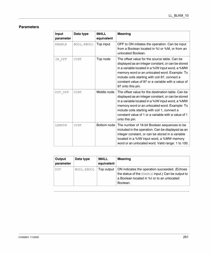
LL_BLKM_10
Parameters
Input parameter
Data type 984LL equivalent
Meaning
ENABLE BOOL, EBOOL Top input OFF to ON initiates the operation. Can be input from a Boolean located in %I or %M, or from an unlocated Boolean.
IN_OFF UINT Top node The offset value for the source table. Can be displayed as an integer constant, or can be stored in a variable located in a %IW input word, a %MW memory word or an unlocated word. Example: To include coils starting with coil 97, connect a constant value of 97 or a variable with a value of 97 onto this pin.
OUT_OFF UINT Middle node The offset value for the destination table. Can be displayed as an integer constant, or can be stored in a variable located in a %IW input word, a %MW memory word or an unlocated word. Example: To include coils starting with coil 1, connect a constant value of 1 or a variable with a value of 1 onto this pin.
LENGTH UINT Bottom node The number of 16-bit Boolean sequences to be included in the operation. Can be displayed as an integer constant, or can be stored in a variable located in a %IW input word, a %MW memory word or an unlocated word. Valid range: 1 to 100.
Output parameter
Data type 984LL equivalent
Meaning
OUT BOOL, EBOOL Top output ON indicates the operation succeeded. (Echoes the status of the ENABLE input.) Can be output to a Boolean located in %I or to an unlocated Boolean.
31006901 11/2005 261

LL_BLKM_10
262 31006901 11/2005

31006901 11/2005
63
LL_BLKM_14: Block Move (%I - %MW)Description
Function Description
The LL_BLKM_14 block move function block copies the entire contents of a source table to a destination table in 1 scan.
Both the source and destination tables consist of 16-bit sequences. The source table consists of %I inputs; the destination table consists of words located in %MW memory. The LENGTH value determines the number of 16-bit sequences included in the block move operation. The IN_OFF offset value defines the location of the source table. The OUT_OFF offset value defines the location of the destination table.
The block move operation begins when the input to the ENABLE pin is turned ON. LL_BLKM_14 can activate a single output. The OUT output turns ON upon the successful completion of the operation.
EN and ENO can be configured as additional parameters.
263

LL_BLKM_14
Representation in FBD
Representation in LD
Representation in IL
CAL LL_BLKM_14_Instance (ENABLE:=Trigger, IN_OFF:=Source, OUT_OFF:=Destination, LENGTH:=Integer1, OUT=>Success
Representation in ST
LL_BLKM_14_Instance (ENABLE:=Trigger, IN_OFF:=Source, OUT_OFF:=Destination, LENGTH:=Integer1, OUT=>Success;
LL_BLKM_14
TriggerSource
LL_BLKM_14_Instance
OUTENABLEIN_OFFOUT_OFFLENGTH
DestinationInteger1
Success
Trigger
Source
ENOENSuccess
LL_BLKM_14LL_BLKM_14_Instance
OUTENABLE
IN_OFF
OUT_OFF
LENGTH
Destination
Integer1
264 31006901 11/2005
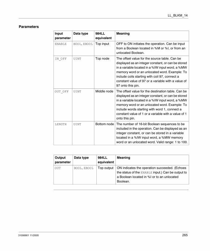
LL_BLKM_14
Parameters
Input parameter
Data type 984LL equivalent
Meaning
ENABLE BOOL, EBOOL Top input OFF to ON initiates the operation. Can be input from a Boolean located in %M or %I, or from an unlocated Boolean.
IN_OFF UINT Top node The offset value for the source table. Can be displayed as an integer constant, or can be stored in a variable located in a %IW input word, a %MW memory word or an unlocated word. Example: To include coils starting with coil 97, connect a constant value of 97 or a variable with a value of 97 onto this pin.
OUT_OFF UINT Middle node The offset value for the destination table. Can be displayed as an integer constant, or can be stored in a variable located in a %IW input word, a %MW memory word or an unlocated word. Example: To include words starting with word 1, connect a constant value of 1 or a variable with a value of 1 onto this pin.
LENGTH UINT Bottom node The number of 16-bit Boolean sequences to be included in the operation. Can be displayed as an integer constant, or can be stored in a variable located in a %IW input word, a %MW memory word or an unlocated word. Valid range: 1 to 100.
Output parameter
Data type 984LL equivalent
Meaning
OUT BOOL, EBOOL Top output ON indicates the operation succeeded. (Echoes the status of the ENABLE input.) Can be output to a Boolean located in %I or to an unlocated Boolean.
31006901 11/2005 265

LL_BLKM_14
266 31006901 11/2005

31006901 11/2005
64
LL_BLKM_30: Block Move (%IW - %M)Description
Function Description
The LL_BLKM_30 block move function block copies the entire contents of a source table to a destination table in 1 scan.
Both the source and destination tables consist of 16-bit sequences. The source table consists of %IW input words; the destination table consists of outputs located in %M memory. The LENGTH value determines the number of 16-bit sequences included in the block move operation. The IN_OFF offset value defines the location of the source table. The OUT_OFF offset value defines the location of the destination table.
The block move operation begins when the input to the ENABLE pin is turned ON. LL_BLKM_30 can activate a single output. The OUT output turns ON upon the successful completion of the operation.
EN and ENO can be configured as additional parameters.
Note: The LL_BLKM_30 function block will not write to and change the state of any EBOOL that has been forced in the Unity Pro Animation Table.
267

LL_BLKM_30
Representation in FBD
Representation in LD
Representation in IL
CAL LL_BLKM_30_Instance (ENABLE:=Trigger, IN_OFF:=Source, OUT_OFF:=Destination, LENGTH:=Integer1, OUT=>Success
Representation in ST
LL_BLKM_30_Instance (ENABLE:=Trigger, IN_OFF:=Source, OUT_OFF:=Destination, LENGTH:=Integer1, OUT=>Success;
LL_BLKM_30
TriggerSource
LL_BLKM_30_Instance
OUTENABLEIN_OFFOUT_OFFLENGTH
DestinationInteger1
Success
Trigger
Source
ENOENSuccess
LL_BLKM_30LL_BLKM_30_Instance
OUTENABLE
IN_OFF
OUT_OFF
LENGTH
Destination
Integer1
268 31006901 11/2005
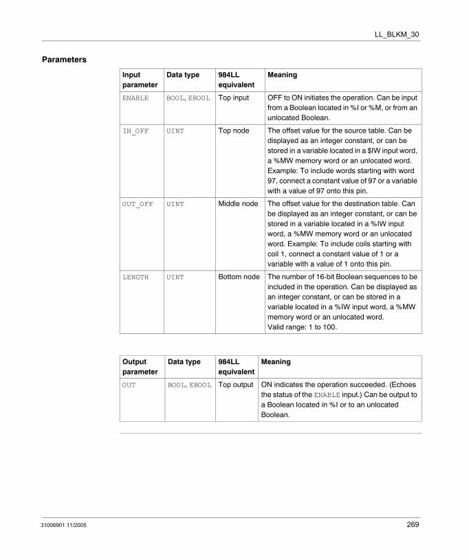
LL_BLKM_30
Parameters
Input parameter
Data type 984LL equivalent
Meaning
ENABLE BOOL, EBOOL Top input OFF to ON initiates the operation. Can be input from a Boolean located in %I or %M, or from an unlocated Boolean.
IN_OFF UINT Top node The offset value for the source table. Can be displayed as an integer constant, or can be stored in a variable located in a $IW input word, a %MW memory word or an unlocated word. Example: To include words starting with word 97, connect a constant value of 97 or a variable with a value of 97 onto this pin.
OUT_OFF UINT Middle node The offset value for the destination table. Can be displayed as an integer constant, or can be stored in a variable located in a %IW input word, a %MW memory word or an unlocated word. Example: To include coils starting with coil 1, connect a constant value of 1 or a variable with a value of 1 onto this pin.
LENGTH UINT Bottom node The number of 16-bit Boolean sequences to be included in the operation. Can be displayed as an integer constant, or can be stored in a variable located in a %IW input word, a %MW memory word or an unlocated word. Valid range: 1 to 100.
Output parameter
Data type 984LL equivalent
Meaning
OUT BOOL, EBOOL Top output ON indicates the operation succeeded. (Echoes the status of the ENABLE input.) Can be output to a Boolean located in %I or to an unlocated Boolean.
31006901 11/2005 269

LL_BLKM_30
270 31006901 11/2005
31006901 11/2005
65
LL_BLKM_34: Block Move (%IW - %MW)Description
Function Description
The LL_BLKM_34 block move function block copies the entire contents of a source table to a destination table in 1 scan.
Both the source and destination tables consist of 16-bit sequences. The source table consists of %IW input words; the destination table consists of words located in %MW memory. The LENGTH value determines the number of 16-bit sequences included in the block move operation. The IN_OFF offset value defines the location of the source table. The OUT_OFF offset value defines the location of the destination table.
The block move operation begins when the input to the ENABLE pin is turned ON. LL_BLKM_34 can activate a single output. The OUT output turns ON upon the successful completion of the operation.
EN and ENO can be configured as additional parameters.
271

LL_BLKM_34
Representation in FBD
Representation in LD
Representation in IL
CAL LL_BLKM_34_Instance (ENABLE:=Trigger, IN_OFF:=Source, OUT_OFF:=Destination, LENGTH:=Integer1, OUT=>Success
Representation in ST
LL_BLKM_34_Instance (ENABLE:=Trigger, IN_OFF:=Source, OUT_OFF:=Destination, LENGTH:=Integer1, OUT=>Success;
LL_BLKM_34
TriggerSource
LL_BLKM_34_Instance
OUTENABLEIN_OFFOUT_OFFLENGTH
DestinationInteger1
Success
Trigger
Source
ENOENSuccess
LL_BLKM_34LL_BLKM_34_Instance
OUTENABLE
IN_OFF
OUT_OFF
LENGTH
Destination
Integer1
272 31006901 11/2005
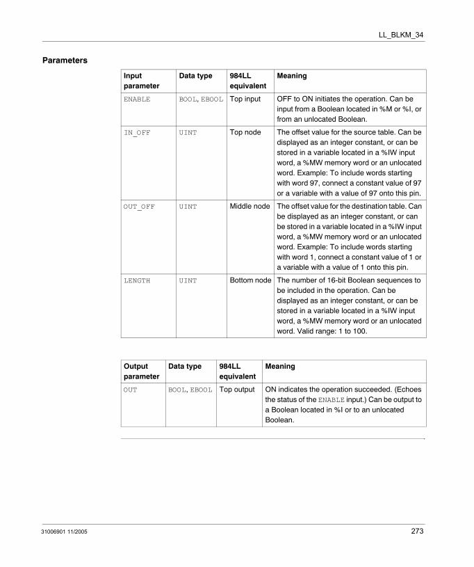
LL_BLKM_34
Parameters
Input parameter
Data type 984LL equivalent
Meaning
ENABLE BOOL, EBOOL Top input OFF to ON initiates the operation. Can be input from a Boolean located in %M or %I, or from an unlocated Boolean.
IN_OFF UINT Top node The offset value for the source table. Can be displayed as an integer constant, or can be stored in a variable located in a %IW input word, a %MW memory word or an unlocated word. Example: To include words starting with word 97, connect a constant value of 97 or a variable with a value of 97 onto this pin.
OUT_OFF UINT Middle node The offset value for the destination table. Can be displayed as an integer constant, or can be stored in a variable located in a %IW input word, a %MW memory word or an unlocated word. Example: To include words starting with word 1, connect a constant value of 1 or a variable with a value of 1 onto this pin.
LENGTH UINT Bottom node The number of 16-bit Boolean sequences to be included in the operation. Can be displayed as an integer constant, or can be stored in a variable located in a %IW input word, a %MW memory word or an unlocated word. Valid range: 1 to 100.
Output parameter
Data type 984LL equivalent
Meaning
OUT BOOL, EBOOL Top output ON indicates the operation succeeded. (Echoes the status of the ENABLE input.) Can be output to a Boolean located in %I or to an unlocated Boolean.
31006901 11/2005 273

LL_BLKM_34
274 31006901 11/2005

31006901 11/2005
66
LL_BLKM_40: Block Move (%MW - %M)Description
Function Description
The LL_BLKM_40 block move function block copies the entire contents of a source table to a destination table in 1 scan.
Both the source and destination tables consist of 16-bit sequences. The source table consists of words located in %MW memory; the destination table consists of outputs located in %M memory. The LENGTH value determines the number of 16-bit sequences included in the block move operation. The IN_OFF offset value defines the location of the source table. The OUT_OFF offset value defines the location of the destination table.
The block move operation begins when the input to the ENABLE pin is turned ON. LL_BLKM_40 can activate a single output. The OUT output turns ON upon the successful completion of the operation.
EN and ENO can be configured as additional parameters.
Note: The LL_BLKM_40 function block will not write to and change the state of any EBOOL that has been forced in the Unity Pro Animation Table.
275
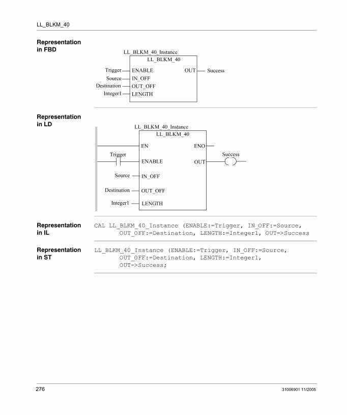
LL_BLKM_40
Representation in FBD
Representation in LD
Representation in IL
CAL LL_BLKM_40_Instance (ENABLE:=Trigger, IN_OFF:=Source, OUT_OFF:=Destination, LENGTH:=Integer1, OUT=>Success
Representation in ST
LL_BLKM_40_Instance (ENABLE:=Trigger, IN_OFF:=Source, OUT_OFF:=Destination, LENGTH:=Integer1, OUT=>Success;
LL_BLKM_40
TriggerSource
LL_BLKM_40_Instance
OUTENABLEIN_OFFOUT_OFFLENGTH
DestinationInteger1
Success
Trigger
Source
ENOENSuccess
LL_BLKM_40LL_BLKM_40_Instance
OUTENABLE
IN_OFF
OUT_OFF
LENGTH
Destination
Integer1
276 31006901 11/2005
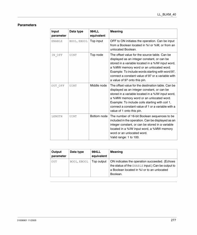
LL_BLKM_40
Parameters
Input parameter
Data type 984LL equivalent
Meaning
ENABLE BOOL, EBOOL Top input OFF to ON initiates the operation. Can be input from a Boolean located in %I or %M, or from an unlocated Boolean.
IN_OFF UINT Top node The offset value for the source table. Can be displayed as an integer constant, or can be stored in a variable located in a %IW input word, a %MW memory word or an unlocated word. Example: To include words starting with word 97, connect a constant value of 97 or a variable with a value of 97 onto this pin.
OUT_OFF UINT Middle node The offset value for the destination table. Can be displayed as an integer constant, or can be stored in a variable located in a %IW input word, a %MW memory word or an unlocated word. Example: To include coils starting with coil 1, connect a constant value of 1 or a variable with a value of 1 onto this pin.
LENGTH UINT Bottom node The number of 16-bit Boolean sequences to be included in the operation. Can be displayed as an integer constant, or can be stored in a variable located in a %IW input word, a %MW memory word or an unlocated word. Valid range: 1 to 100.
Output parameter
Data type 984LL equivalent
Meaning
OUT BOOL, EBOOL Top output ON indicates the operation succeeded. (Echoes the status of the ENABLE input.) Can be output to a Boolean located in %I or to an unlocated Boolean.
31006901 11/2005 277

LL_BLKM_40
278 31006901 11/2005
31006901 11/2005
67
LL_BLKM_44: Block Move (%MW - %MW)Description
Function Description
The LL_BLKM_44 block move function block copies the entire contents of a source table to a destination table in 1 scan.
Both the source and destination matrices consist of 16-bit sequences made up of words located in %MW memory. The LENGTH value determines the number of 16-bit sequences included in the block move operation. The IN_OFF offset value defines the location of the source table. The OUT_OFF offset value defines the location of the destination table.
The block move operation begins when the input to the ENABLE pin is turned ON. LL_BLKM_44 can activate a single output. The OUT output turns ON upon the successful completion of the operation.
EN and ENO can be configured as additional parameters.
279
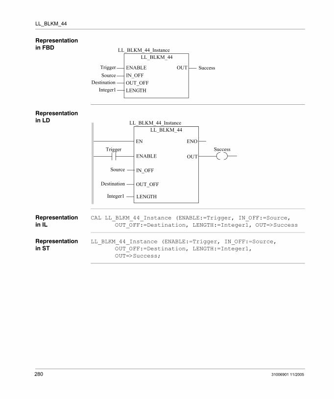
LL_BLKM_44
Representation in FBD
Representation in LD
Representation in IL
CAL LL_BLKM_44_Instance (ENABLE:=Trigger, IN_OFF:=Source, OUT_OFF:=Destination, LENGTH:=Integer1, OUT=>Success
Representation in ST
LL_BLKM_44_Instance (ENABLE:=Trigger, IN_OFF:=Source, OUT_OFF:=Destination, LENGTH:=Integer1, OUT=>Success;
LL_BLKM_44
TriggerSource
LL_BLKM_44_Instance
OUTENABLEIN_OFFOUT_OFFLENGTH
DestinationInteger1
Success
Trigger
Source
ENOENSuccess
LL_BLKM_44LL_BLKM_44_Instance
OUTENABLE
IN_OFF
OUT_OFF
LENGTH
Destination
Integer1
280 31006901 11/2005
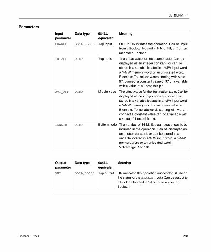
LL_BLKM_44
Parameters
Input parameter
Data type 984LL equivalent
Meaning
ENABLE BOOL, EBOOL Top input OFF to ON initiates the operation. Can be input from a Boolean located in %M or %I, or from an unlocated Boolean.
IN_OFF UINT Top node The offset value for the source table. Can be displayed as an integer constant, or can be stored in a variable located in a %IW input word, a %MW memory word or an unlocated word. Example: To include words starting with word 97, connect a constant value of 97 or a variable with a value of 97 onto this pin.
OUT_OFF UINT Middle node The offset value for the destination table. Can be displayed as an integer constant, or can be stored in a variable located in a %IW input word, a %MW memory word or an unlocated word. Example: To include words starting with word 1, connect a constant value of 1 or a variable with a value of 1 onto this pin.
LENGTH UINT Bottom node The number of 16-bit Boolean sequences to be included in the operation. Can be displayed as an integer constant, or can be stored in a variable located in a %IW input word, a %MW memory word or an unlocated word. Valid range: 1 to 100.
Output parameter
Data type 984LL equivalent
Meaning
OUT BOOL, EBOOL Top output ON indicates the operation succeeded. (Echoes the status of the ENABLE input.) Can be output to a Boolean located in %I or to an unlocated Boolean.
31006901 11/2005 281

LL_BLKM_44
282 31006901 11/2005
31006901 11/2005
68
LL_BLKT: Block to TableDescription
Function Description
The LL_BLKT block-to-table function block combines the functionality of a block move instruction with a register to table instruction. In a single scan, it can copy data from a source block of located words to a destination block of located words in a table. The length of the source block is fixed. Each destination block within the table must be the same length as the source block. However, the overall size of the destination table is limited only by the number of words in your system configuration.
Both the source block and destination table consist of words located in %MW memory. The LENGTH value determines the number of words included in the source block. The IN_OFF offset value defines the location of the first word in the source block of words.
Risk of unintended operation.The LL_BLKT is a powerful instruction that can overwrite all the %MW words in your PLC with data copied from the source connected to the IN_OFF input. Use external logic to confine the pointer value to a safe range.For example:
Use an LL_SUB function block to compare the pointer value to the beginning of the range of %MW words you do not want to overwrite.Attach a coil to the GRT and EQT outputs of the LL_SUB block.Connect the GRT and EQT coils of the LL_SUB block to a normally closed contact connected to the ENABLE pin of the LL_BLKT block.
Failure to follow this instruction can result in death, serious injury, or equipment damage.
WARNING
283
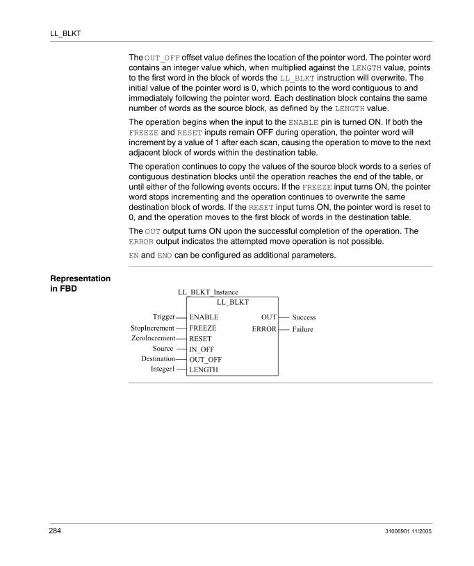
LL_BLKT
The OUT_OFF offset value defines the location of the pointer word. The pointer word contains an integer value which, when multiplied against the LENGTH value, points to the first word in the block of words the LL_BLKT instruction will overwrite. The initial value of the pointer word is 0, which points to the word contiguous to and immediately following the pointer word. Each destination block contains the same number of words as the source block, as defined by the LENGTH value.
The operation begins when the input to the ENABLE pin is turned ON. If both the FREEZE and RESET inputs remain OFF during operation, the pointer word will increment by a value of 1 after each scan, causing the operation to move to the next adjacent block of words within the destination table.
The operation continues to copy the values of the source block words to a series of contiguous destination blocks until the operation reaches the end of the table, or until either of the following events occurs. If the FREEZE input turns ON, the pointer word stops incrementing and the operation continues to overwrite the same destination block of words. If the RESET input turns ON, the pointer word is reset to 0, and the operation moves to the first block of words in the destination table.
The OUT output turns ON upon the successful completion of the operation. The ERROR output indicates the attempted move operation is not possible.
EN and ENO can be configured as additional parameters.
Representation in FBD
LL_BLKT
TriggerStopIncrement
LL_BLKT_Instance
OUTENABLEFREEZERESETIN_OFF
ZeroIncrementSource
SuccessERROR Failure
OUT_OFFDestinationLENGTHInteger1
284 31006901 11/2005
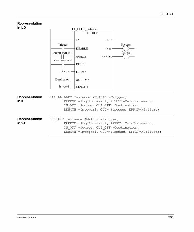
LL_BLKT
Representation in LD
Representation in IL
CAL LL_BLKT_Instance (ENABLE:=Trigger, FREEZE:=StopIncrement, RESET:=ZeroIncrement, IN_OFF:=Source, OUT_OFF:=Destination, LENGTH:=Integer1, OUT=>Success, ERROR=>Failure)
Representation in ST
LL_BLKT_Instance (ENABLE:=Trigger, FREEZE:=StopIncrement, RESET:=ZeroIncrement, IN_OFF:=Source, OUT_OFF:=Destination, LENGTH:=Integer1, OUT=>Success, ERROR=>Failure);
Trigger
Source
ENOENSuccess
LL_BLKTLL_BLKT_Instance
OUTENABLE
IN_OFF
OUT_OFF
LENGTH
Destination
Integer1
FailureERROR
ZeroIncrementRESET
StopIncrementFREEZE
31006901 11/2005 285
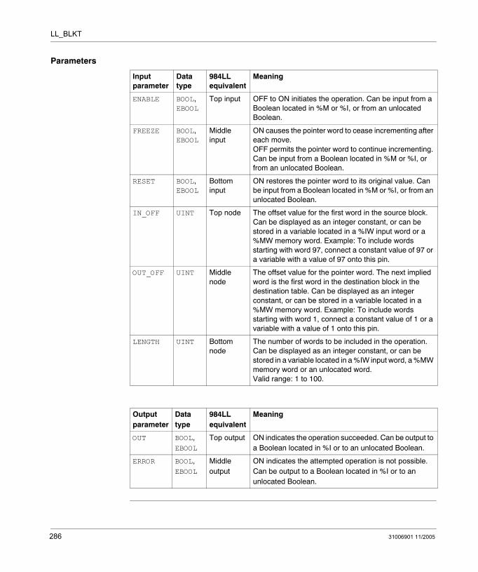
LL_BLKT
Parameters
Input parameter
Data type
984LL equivalent
Meaning
ENABLE BOOL, EBOOL
Top input OFF to ON initiates the operation. Can be input from a Boolean located in %M or %I, or from an unlocated Boolean.
FREEZE BOOL, EBOOL
Middle input
ON causes the pointer word to cease incrementing after each move. OFF permits the pointer word to continue incrementing. Can be input from a Boolean located in %M or %I, or from an unlocated Boolean.
RESET BOOL, EBOOL
Bottom input
ON restores the pointer word to its original value. Can be input from a Boolean located in %M or %I, or from an unlocated Boolean.
IN_OFF UINT Top node The offset value for the first word in the source block. Can be displayed as an integer constant, or can be stored in a variable located in a %IW input word or a %MW memory word. Example: To include words starting with word 97, connect a constant value of 97 or a variable with a value of 97 onto this pin.
OUT_OFF UINT Middle node
The offset value for the pointer word. The next implied word is the first word in the destination block in the destination table. Can be displayed as an integer constant, or can be stored in a variable located in a %MW memory word. Example: To include words starting with word 1, connect a constant value of 1 or a variable with a value of 1 onto this pin.
LENGTH UINT Bottom node
The number of words to be included in the operation. Can be displayed as an integer constant, or can be stored in a variable located in a %IW input word, a %MW memory word or an unlocated word. Valid range: 1 to 100.
Output parameter
Data type
984LL equivalent
Meaning
OUT BOOL, EBOOL
Top output ON indicates the operation succeeded. Can be output to a Boolean located in %I or to an unlocated Boolean.
ERROR BOOL, EBOOL
Middle output
ON indicates the attempted operation is not possible. Can be output to a Boolean located in %I or to an unlocated Boolean.
286 31006901 11/2005

31006901 11/2005
69
LL_FIN_04: First In (%M - %MW)Description
Function Description
The LL_FIN_04 function block produces a first-in queue. It copies source data from a 16-bit Boolean sequence located in %M memory to the first - or top - word in a queue of words located in %MW memory. After all words in the queue have been filled, no additional source data can be copied to the queue.
The LENGTH value determines the number of words in the destination queue. The IN_OFF offset value defines the location of the first bit in the source 16-bit Boolean sequence. The OUT_OFF offset value defines the location of the queue pointer. The queue pointer contains the number of filled words in the queue. The word contiguous to and following the pointer word is the first - or top - word in the queue.
The operation begins when the input to the ENABLE pin is turned ON. The queue pointer’s initial value is 0, and increments by 1 each time source data is copied to the queue. Source data is always copied to the memory word at the top of the queue. If the top word holds previously copied source data, that data is transferred to the next memory word in the queue, and so on for every memory word in the queue. When the queue pointer value equals the LENGTH value, the queue is filled and no additional source data can be added to the queue.
Note: When the queue is filled, use either the LL_FOUT_04 or LL_FOUT_44 function block to clear the last - or bottom - word in the queue.
11111111LL_FIN_04
22222222LL_FIN_04
111133333333
LL_FIN_04
2222
1111
SourceSource Source
QueueQueueQueue
Pointer1
Pointer2
Pointer3
287
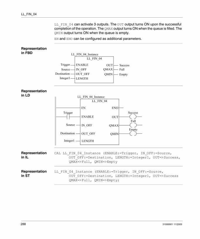
LL_FIN_04
LL_FIN_04 can activate 3 outputs. The OUT output turns ON upon the successful completion of the operation. The QMAX output turns ON when the queue is filled. The QMIN output turns ON when the queue is empty.
EN and ENO can be configured as additional parameters.
Representation in FBD
Representation in LD
Representation in IL
CAL LL_FIN_04_Instance (ENABLE:=Trigger, IN_OFF:=Source, OUT_OFF:=Destination, LENGTH:=Integer1, OUT=>Success, QMAX=>Full, QMIN=>Empty
Representation in ST
LL_FIN_04_Instance (ENABLE:=Trigger, IN_OFF:=Source, OUT_OFF:=Destination, LENGTH:=Integer1, OUT=>Success QMAX=>Full, QMIN=>Empty;
LL_FIN_04
TriggerSource
LL_FIN_04_Instance
OUTENABLEIN_OFFOUT_OFFLENGTH
DestinationInteger1
SuccessQMAX FullQMIN Empty
Trigger
Source
ENOENSuccess
LL_FIN_04LL_FIN_04_Instance
OUTENABLE
IN_OFF
OUT_OFF
LENGTH
Destination
Integer1
FullQMAX
EmptyQMIN
288 31006901 11/2005
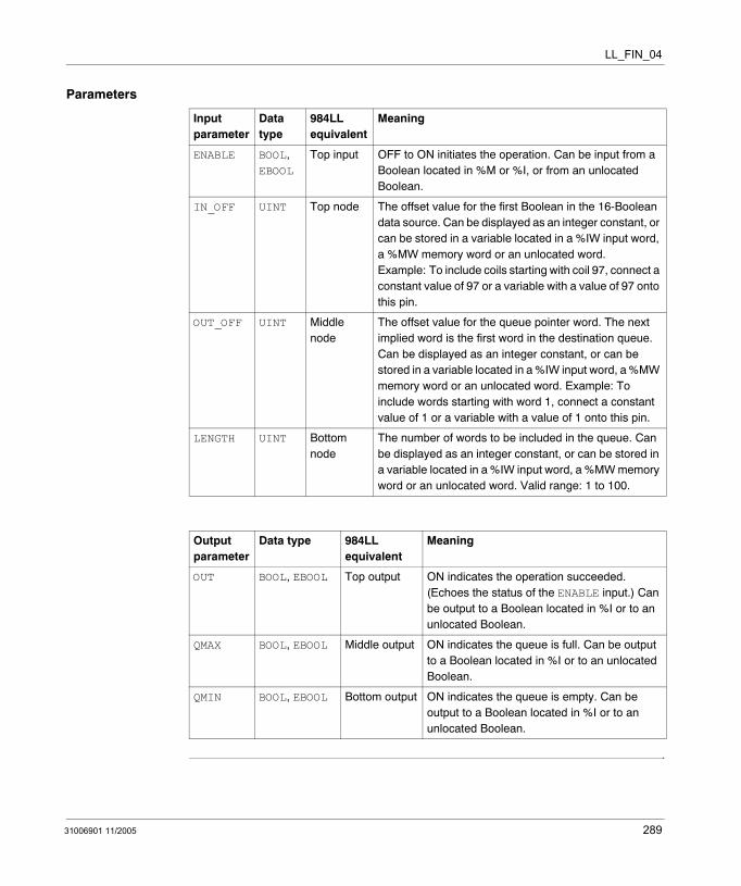
LL_FIN_04
Parameters
Input parameter
Data type
984LL equivalent
Meaning
ENABLE BOOL, EBOOL
Top input OFF to ON initiates the operation. Can be input from a Boolean located in %M or %I, or from an unlocated Boolean.
IN_OFF UINT Top node The offset value for the first Boolean in the 16-Boolean data source. Can be displayed as an integer constant, or can be stored in a variable located in a %IW input word, a %MW memory word or an unlocated word. Example: To include coils starting with coil 97, connect a constant value of 97 or a variable with a value of 97 onto this pin.
OUT_OFF UINT Middle node
The offset value for the queue pointer word. The next implied word is the first word in the destination queue. Can be displayed as an integer constant, or can be stored in a variable located in a %IW input word, a %MW memory word or an unlocated word. Example: To include words starting with word 1, connect a constant value of 1 or a variable with a value of 1 onto this pin.
LENGTH UINT Bottom node
The number of words to be included in the queue. Can be displayed as an integer constant, or can be stored in a variable located in a %IW input word, a %MW memory word or an unlocated word. Valid range: 1 to 100.
Output parameter
Data type 984LL equivalent
Meaning
OUT BOOL, EBOOL Top output ON indicates the operation succeeded. (Echoes the status of the ENABLE input.) Can be output to a Boolean located in %I or to an unlocated Boolean.
QMAX BOOL, EBOOL Middle output ON indicates the queue is full. Can be output to a Boolean located in %I or to an unlocated Boolean.
QMIN BOOL, EBOOL Bottom output ON indicates the queue is empty. Can be output to a Boolean located in %I or to an unlocated Boolean.
31006901 11/2005 289

LL_FIN_04
290 31006901 11/2005
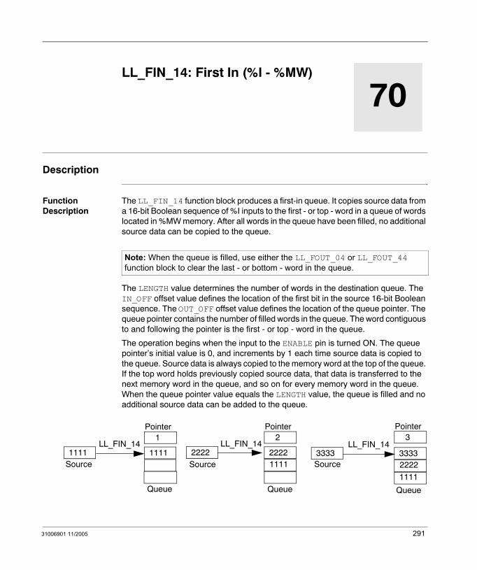
31006901 11/2005
70
LL_FIN_14: First In (%I - %MW)Description
Function Description
The LL_FIN_14 function block produces a first-in queue. It copies source data from a 16-bit Boolean sequence of %I inputs to the first - or top - word in a queue of words located in %MW memory. After all words in the queue have been filled, no additional source data can be copied to the queue.
The LENGTH value determines the number of words in the destination queue. The IN_OFF offset value defines the location of the first bit in the source 16-bit Boolean sequence. The OUT_OFF offset value defines the location of the queue pointer. The queue pointer contains the number of filled words in the queue. The word contiguous to and following the pointer is the first - or top - word in the queue.
The operation begins when the input to the ENABLE pin is turned ON. The queue pointer’s initial value is 0, and increments by 1 each time source data is copied to the queue. Source data is always copied to the memory word at the top of the queue. If the top word holds previously copied source data, that data is transferred to the next memory word in the queue, and so on for every memory word in the queue. When the queue pointer value equals the LENGTH value, the queue is filled and no additional source data can be added to the queue.
Note: When the queue is filled, use either the LL_FOUT_04 or LL_FOUT_44 function block to clear the last - or bottom - word in the queue.
11111111LL_FIN_14
22222222LL_FIN_14
111133333333
LL_FIN_14
2222
1111
SourceSource Source
QueueQueueQueue
Pointer1
Pointer2
Pointer3
291

LL_FIN_14
LL_FIN_14 can activate 3 outputs. The OUT output turns ON upon the successful completion of the operation. The QMAX output turns ON when the queue is filled. The QMIN output turns ON when the queue is empty.
EN and ENO can be configured as additional parameters.
Representation in FBD
Representation in LD
Representation in IL
CAL LL_FIN_14_Instance (ENABLE:=Trigger, IN_OFF:=Source, OUT_OFF:=Destination, LENGTH:=Integer1, OUT=>Success, QMAX=>Full, QMIN=>Empty
Representation in ST
LL_FIN_14_Instance (ENABLE:=Trigger, IN_OFF:=Source, OUT_OFF:=Destination, LENGTH:=Integer1, OUT=>Success QMAX=>Full, QMIN=>Empty;
LL_FIN_14
TriggerSource
LL_FIN_14_Instance
OUTENABLEIN_OFFOUT_OFFLENGTH
DestinationInteger1
SuccessQMAX FullQMIN Empty
Trigger
Source
ENOENSuccess
LL_FIN_14LL_FIN_14_Instance
OUTENABLE
IN_OFF
OUT_OFF
LENGTH
Destination
Integer1
FullQMAX
EmptyQMIN
292 31006901 11/2005
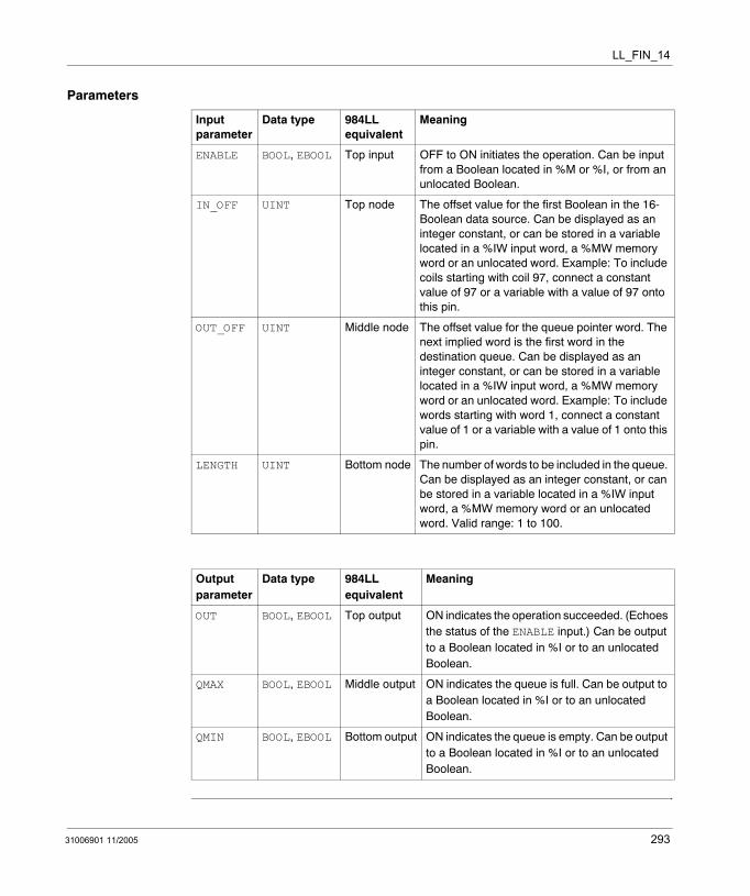
LL_FIN_14
Parameters
Input parameter
Data type 984LL equivalent
Meaning
ENABLE BOOL, EBOOL Top input OFF to ON initiates the operation. Can be input from a Boolean located in %M or %I, or from an unlocated Boolean.
IN_OFF UINT Top node The offset value for the first Boolean in the 16-Boolean data source. Can be displayed as an integer constant, or can be stored in a variable located in a %IW input word, a %MW memory word or an unlocated word. Example: To include coils starting with coil 97, connect a constant value of 97 or a variable with a value of 97 onto this pin.
OUT_OFF UINT Middle node The offset value for the queue pointer word. The next implied word is the first word in the destination queue. Can be displayed as an integer constant, or can be stored in a variable located in a %IW input word, a %MW memory word or an unlocated word. Example: To include words starting with word 1, connect a constant value of 1 or a variable with a value of 1 onto this pin.
LENGTH UINT Bottom node The number of words to be included in the queue. Can be displayed as an integer constant, or can be stored in a variable located in a %IW input word, a %MW memory word or an unlocated word. Valid range: 1 to 100.
Output parameter
Data type 984LL equivalent
Meaning
OUT BOOL, EBOOL Top output ON indicates the operation succeeded. (Echoes the status of the ENABLE input.) Can be output to a Boolean located in %I or to an unlocated Boolean.
QMAX BOOL, EBOOL Middle output ON indicates the queue is full. Can be output to a Boolean located in %I or to an unlocated Boolean.
QMIN BOOL, EBOOL Bottom output ON indicates the queue is empty. Can be output to a Boolean located in %I or to an unlocated Boolean.
31006901 11/2005 293

LL_FIN_14
294 31006901 11/2005
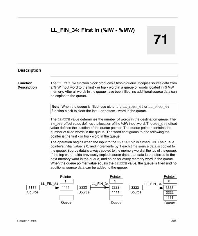
31006901 11/2005
71
LL_FIN_34: First In (%IW - %MW)Description
Function Description
The LL_FIN_34 function block produces a first-in queue. It copies source data from a %IW input word to the first - or top - word in a queue of words located in %MW memory. After all words in the queue have been filled, no additional source data can be copied to the queue.
The LENGTH value determines the number of words in the destination queue. The IN_OFF offset value defines the location of the %IW input word. The OUT_OFF offset value defines the location of the queue pointer. The queue pointer contains the number of filled words in the queue. The word contiguous to and following the pointer is the first - or top - word in the queue.
The operation begins when the input to the ENABLE pin is turned ON. The queue pointer’s initial value is 0, and increments by 1 each time source data is copied to the queue. Source data is always copied to the memory word at the top of the queue. If the top word holds previously copied source data, that data is transferred to the next memory word in the queue, and so on for every memory word in the queue. When the queue pointer value equals the LENGTH value, the queue is filled and no additional source data can be added to the queue.
Note: When the queue is filled, use either the LL_FOUT_04 or LL_FOUT_44 function block to clear the last - or bottom - word in the queue.
11111111LL_FIN_34
22222222LL_FIN_34
111133333333
LL_FIN_34
2222
1111
SourceSource Source
QueueQueueQueue
Pointer1
Pointer2
Pointer3
295

LL_FIN_34
LL_FIN_34 can activate 3 outputs. The OUT output turns ON upon the successful completion of the operation. The QMAX output turns ON when the queue is filled. The QMIN output turns ON when the queue is empty.
EN and ENO can be configured as additional parameters.
Representation in FBD
Representation in LD
Representation in IL
CAL LL_FIN_34_Instance (ENABLE:=Trigger, IN_OFF:=Source, OUT_OFF:=Destination, LENGTH:=Integer1, OUT=>Success, QMAX=>Full, QMIN=>Empty
Representation in ST
LL_FIN_34_Instance (ENABLE:=Trigger, IN_OFF:=Source, OUT_OFF:=Destination, LENGTH:=Integer1, OUT=>Success QMAX=>Full, QMIN=>Empty;
LL_FIN_34
TriggerSource
LL_FIN_34_Instance
OUTENABLEIN_OFFOUT_OFFLENGTH
DestinationInteger1
SuccessQMAX FullQMIN Empty
Trigger
Source
ENOENSuccess
LL_FIN_34LL_FIN_34_Instance
OUTENABLE
IN_OFF
OUT_OFF
LENGTH
Destination
Integer1
FullQMAX
EmptyQMIN
296 31006901 11/2005
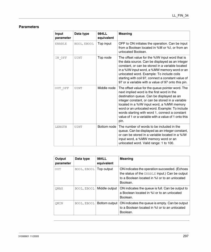
LL_FIN_34
Parameters
Input parameter
Data type 984LL equivalent
Meaning
ENABLE BOOL, EBOOL Top input OFF to ON initiates the operation. Can be input from a Boolean located in %M or %I, or from an unlocated Boolean.
IN_OFF UINT Top node The offset value for the %IW input word that is the data source. Can be displayed as an integer constant, or can be stored in a variable located in a %IW input word, a %MW memory word or an unlocated word. Example: To include coils starting with coil 97, connect a constant value of 97 or a variable with a value of 97 onto this pin.
OUT_OFF UINT Middle node The offset value for the queue pointer word. The next implied word is the first word in the destination queue. Can be displayed as an integer constant, or can be stored in a variable located in a %IW input word, a %MW memory word or an unlocated word. Example: To include words starting with word 1, connect a constant value of 1 or a variable with a value of 1 onto this pin.
LENGTH UINT Bottom node The number of words to be included in the queue. Can be displayed as an integer constant, or can be stored in a variable located in a %IW input word, a %MW memory word or an unlocated word. Valid range: 1 to 100.
Output parameter
Data type 984LL equivalent
Meaning
OUT BOOL, EBOOL Top output ON indicates the operation succeeded. (Echoes the status of the ENABLE input.) Can be output to a Boolean located in %I or to an unlocated Boolean.
QMAX BOOL, EBOOL Middle output ON indicates the queue is full. Can be output to a Boolean located in %I or to an unlocated Boolean.
QMIN BOOL, EBOOL Bottom output ON indicates the queue is empty. Can be output to a Boolean located in %I or to an unlocated Boolean.
31006901 11/2005 297

LL_FIN_34
298 31006901 11/2005
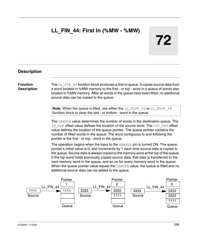
31006901 11/2005
72
LL_FIN_44: First In (%MW - %MW)Description
Function Description
The LL_FIN_44 function block produces a first-in queue. It copies source data from a word located in %MW memory to the first - or top - word in a queue of words also located in %MW memory. After all words in the queue have been filled, no additional source data can be copied to the queue.
The LENGTH value determines the number of words in the destination queue. The IN_OFF offset value defines the location of the source word. The OUT_OFF offset value defines the location of the queue pointer. The queue pointer contains the number of filled words in the queue. The word contiguous to and following the pointer is the first - or top - word in the queue.
The operation begins when the input to the ENABLE pin is turned ON. The queue pointer’s initial value is 0, and increments by 1 each time source data is copied to the queue. Source data is always copied to the memory word at the top of the queue. If the top word holds previously copied source data, that data is transferred to the next memory word in the queue, and so on for every memory word in the queue. When the queue pointer value equals the LENGTH value, the queue is filled and no additional source data can be added to the queue.
Note: When the queue is filled, use either the LL_FOUT_04 or LL_FOUT_44 function block to clear the last - or bottom - word in the queue.
11111111LL_FIN_44
22222222LL_FIN_44
111133333333
LL_FIN_44
2222
1111
SourceSource Source
QueueQueueQueue
Pointer1
Pointer2
Pointer3
299

LL_FIN_44
LL_FIN_44 can activate 3 outputs. The OUT output turns ON upon the successful completion of the operation. The QMAX output turns ON when the queue is filled. The QMIN output turns ON when the queue is empty.
EN and ENO can be configured as additional parameters.
Representation in FBD
Representation in LD
Representation in IL
CAL LL_FIN_44_Instance (ENABLE:=Trigger, IN_OFF:=Source, OUT_OFF:=Destination, LENGTH:=Integer1, OUT=>Success, QMAX=>Full, QMIN=>Empty
Representation in ST
LL_FIN_44_Instance (ENABLE:=Trigger, IN_OFF:=Source, OUT_OFF:=Destination, LENGTH:=Integer1, OUT=>Success QMAX=>Full, QMIN=>Empty;
LL_FIN_44
TriggerSource
LL_FIN_44_Instance
OUTENABLEIN_OFFOUT_OFFLENGTH
DestinationInteger1
SuccessQMAX FullQMIN Empty
Trigger
Source
ENOENSuccess
LL_FIN_44LL_FIN_44_Instance
OUTENABLE
IN_OFF
OUT_OFF
LENGTH
Destination
Integer1
FullQMAX
EmptyQMIN
300 31006901 11/2005
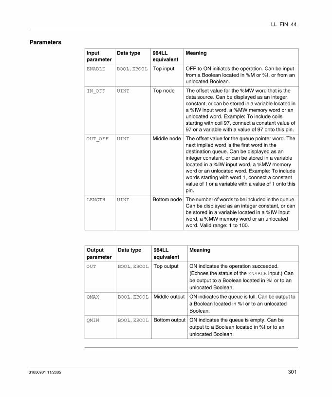
LL_FIN_44
Parameters
Input parameter
Data type 984LL equivalent
Meaning
ENABLE BOOL, EBOOL Top input OFF to ON initiates the operation. Can be input from a Boolean located in %M or %I, or from an unlocated Boolean.
IN_OFF UINT Top node The offset value for the %MW word that is the data source. Can be displayed as an integer constant, or can be stored in a variable located in a %IW input word, a %MW memory word or an unlocated word. Example: To include coils starting with coil 97, connect a constant value of 97 or a variable with a value of 97 onto this pin.
OUT_OFF UINT Middle node The offset value for the queue pointer word. The next implied word is the first word in the destination queue. Can be displayed as an integer constant, or can be stored in a variable located in a %IW input word, a %MW memory word or an unlocated word. Example: To include words starting with word 1, connect a constant value of 1 or a variable with a value of 1 onto this pin.
LENGTH UINT Bottom node The number of words to be included in the queue. Can be displayed as an integer constant, or can be stored in a variable located in a %IW input word, a %MW memory word or an unlocated word. Valid range: 1 to 100.
Output parameter
Data type 984LL equivalent
Meaning
OUT BOOL, EBOOL Top output ON indicates the operation succeeded. (Echoes the status of the ENABLE input.) Can be output to a Boolean located in %I or to an unlocated Boolean.
QMAX BOOL, EBOOL Middle output ON indicates the queue is full. Can be output to a Boolean located in %I or to an unlocated Boolean.
QMIN BOOL, EBOOL Bottom output ON indicates the queue is empty. Can be output to a Boolean located in %I or to an unlocated Boolean.
31006901 11/2005 301

LL_FIN_44
302 31006901 11/2005
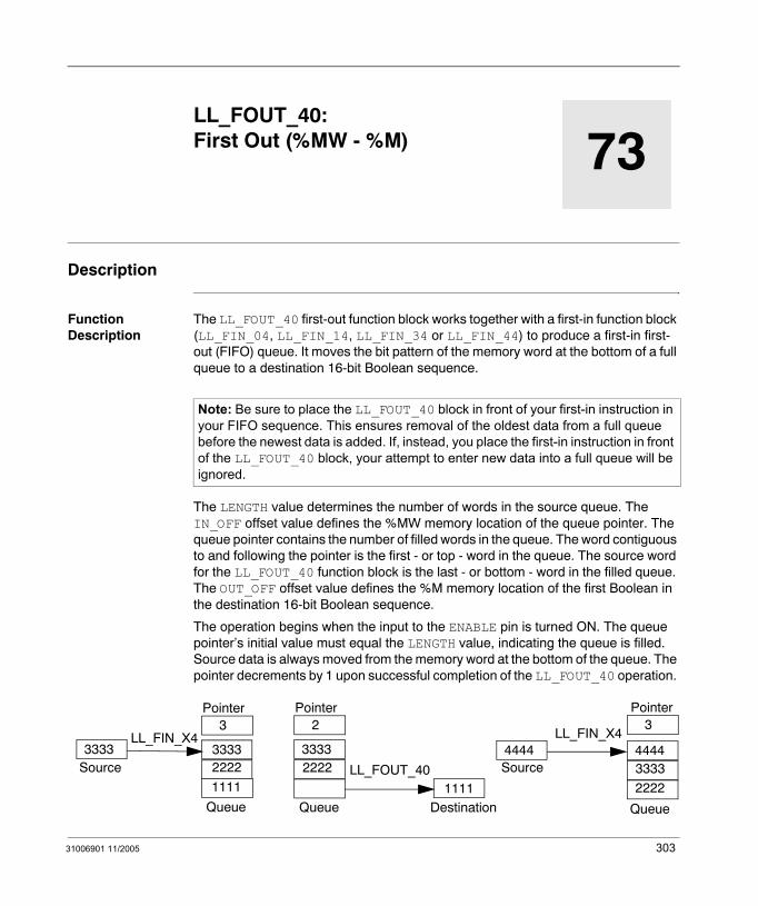
31006901 11/2005
73
LL_FOUT_40: First Out (%MW - %M)Description
Function Description
The LL_FOUT_40 first-out function block works together with a first-in function block (LL_FIN_04, LL_FIN_14, LL_FIN_34 or LL_FIN_44) to produce a first-in first-out (FIFO) queue. It moves the bit pattern of the memory word at the bottom of a full queue to a destination 16-bit Boolean sequence.
The LENGTH value determines the number of words in the source queue. The IN_OFF offset value defines the %MW memory location of the queue pointer. The queue pointer contains the number of filled words in the queue. The word contiguous to and following the pointer is the first - or top - word in the queue. The source word for the LL_FOUT_40 function block is the last - or bottom - word in the filled queue. The OUT_OFF offset value defines the %M memory location of the first Boolean in the destination 16-bit Boolean sequence.
The operation begins when the input to the ENABLE pin is turned ON. The queue pointer’s initial value must equal the LENGTH value, indicating the queue is filled. Source data is always moved from the memory word at the bottom of the queue. The pointer decrements by 1 upon successful completion of the LL_FOUT_40 operation.
Note: Be sure to place the LL_FOUT_40 block in front of your first-in instruction in your FIFO sequence. This ensures removal of the oldest data from a full queue before the newest data is added. If, instead, you place the first-in instruction in front of the LL_FOUT_40 block, your attempt to enter new data into a full queue will be ignored.
33333333LL_FIN_X4
33332222
44444444LL_FIN_X4
3333
2222
Source Source
QueueQueueQueue
Pointer3
Pointer2
Pointer3
2222
1111LL_FOUT_40
1111Destination
303
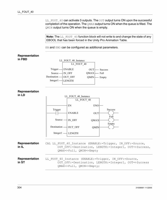
LL_FOUT_40
LL_FOUT_40 can activate 3 outputs. The OUT output turns ON upon the successful completion of the operation. The QMAX output turns ON when the queue is filled. The QMIN output turns ON when the queue is empty.
EN and ENO can be configured as additional parameters.
Representation in FBD
Representation in LD
Representation in IL
CAL LL_FOUT_40_Instance (ENABLE:=Trigger, IN_OFF:=Source, OUT_OFF:=Destination, LENGTH:=Integer1, OUT=>Success, QMAX=>Full, QMIN=>Empty
Representation in ST
LL_FOUT_40_Instance (ENABLE:=Trigger, IN_OFF:=Source, OUT_OFF:=Destination, LENGTH:=Integer1, OUT=>Success QMAX=>Full, QMIN=>Empty;
Note: The LL_FOUT_40 function block will not write to and change the state of any EBOOL that has been forced in the Unity Pro Animation Table.
LL_FOUT_40
TriggerSource
LL_FOUT_40_Instance
OUTENABLEIN_OFFOUT_OFFLENGTH
DestinationInteger1
SuccessQMAX FullQMIN Empty
Trigger
Source
ENOENSuccess
LL_FOUT_40LL_FOUT_40_Instance
OUTENABLE
IN_OFF
OUT_OFF
LENGTH
Destination
Integer1
FullQMAX
EmptyQMIN
304 31006901 11/2005
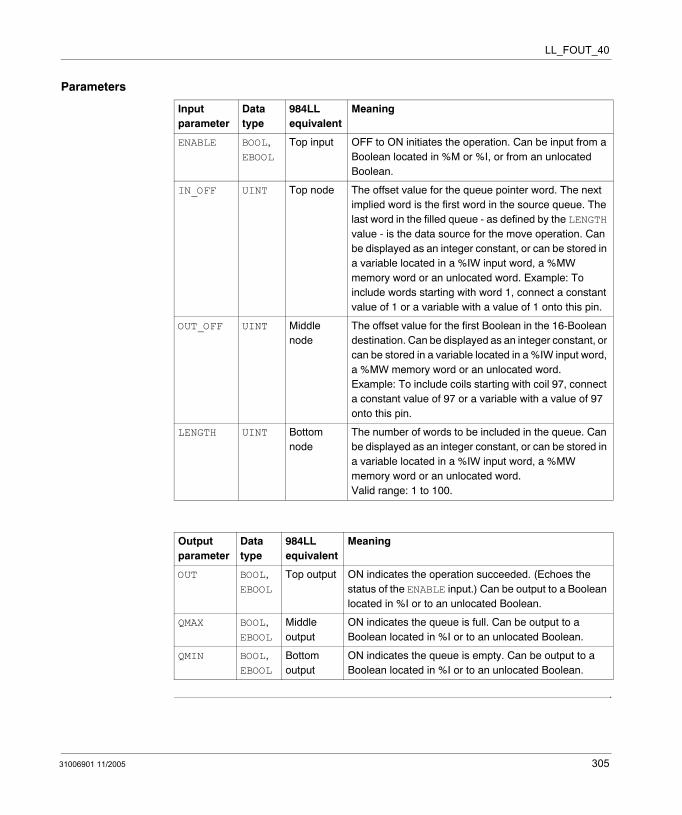
LL_FOUT_40
Parameters
Input parameter
Data type
984LL equivalent
Meaning
ENABLE BOOL, EBOOL
Top input OFF to ON initiates the operation. Can be input from a Boolean located in %M or %I, or from an unlocated Boolean.
IN_OFF UINT Top node The offset value for the queue pointer word. The next implied word is the first word in the source queue. The last word in the filled queue - as defined by the LENGTH value - is the data source for the move operation. Can be displayed as an integer constant, or can be stored in a variable located in a %IW input word, a %MW memory word or an unlocated word. Example: To include words starting with word 1, connect a constant value of 1 or a variable with a value of 1 onto this pin.
OUT_OFF UINT Middle node
The offset value for the first Boolean in the 16-Boolean destination. Can be displayed as an integer constant, or can be stored in a variable located in a %IW input word, a %MW memory word or an unlocated word. Example: To include coils starting with coil 97, connect a constant value of 97 or a variable with a value of 97 onto this pin.
LENGTH UINT Bottom node
The number of words to be included in the queue. Can be displayed as an integer constant, or can be stored in a variable located in a %IW input word, a %MW memory word or an unlocated word. Valid range: 1 to 100.
Output parameter
Data type
984LL equivalent
Meaning
OUT BOOL, EBOOL
Top output ON indicates the operation succeeded. (Echoes the status of the ENABLE input.) Can be output to a Boolean located in %I or to an unlocated Boolean.
QMAX BOOL, EBOOL
Middle output
ON indicates the queue is full. Can be output to a Boolean located in %I or to an unlocated Boolean.
QMIN BOOL, EBOOL
Bottom output
ON indicates the queue is empty. Can be output to a Boolean located in %I or to an unlocated Boolean.
31006901 11/2005 305

LL_FOUT_40
306 31006901 11/2005
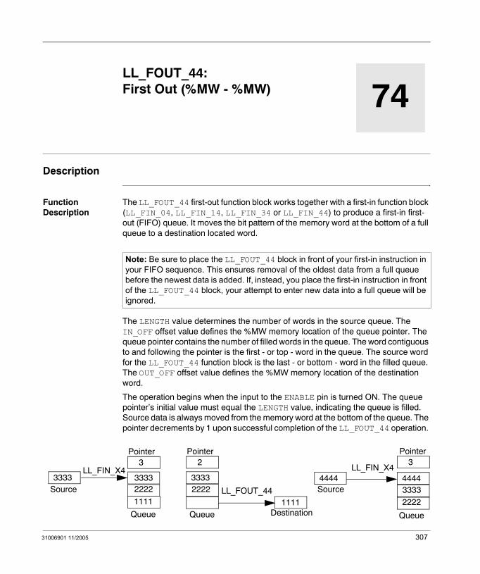
31006901 11/2005
74
LL_FOUT_44: First Out (%MW - %MW)Description
Function Description
The LL_FOUT_44 first-out function block works together with a first-in function block (LL_FIN_04, LL_FIN_14, LL_FIN_34 or LL_FIN_44) to produce a first-in first-out (FIFO) queue. It moves the bit pattern of the memory word at the bottom of a full queue to a destination located word.
The LENGTH value determines the number of words in the source queue. The IN_OFF offset value defines the %MW memory location of the queue pointer. The queue pointer contains the number of filled words in the queue. The word contiguous to and following the pointer is the first - or top - word in the queue. The source word for the LL_FOUT_44 function block is the last - or bottom - word in the filled queue. The OUT_OFF offset value defines the %MW memory location of the destination word.
The operation begins when the input to the ENABLE pin is turned ON. The queue pointer’s initial value must equal the LENGTH value, indicating the queue is filled. Source data is always moved from the memory word at the bottom of the queue. The pointer decrements by 1 upon successful completion of the LL_FOUT_44 operation.
Note: Be sure to place the LL_FOUT_44 block in front of your first-in instruction in your FIFO sequence. This ensures removal of the oldest data from a full queue before the newest data is added. If, instead, you place the first-in instruction in front of the LL_FOUT_44 block, your attempt to enter new data into a full queue will be ignored.
33333333LL_FIN_X4
33332222
44444444LL_FIN_X4
3333
2222
Source Source
QueueQueueQueue
Pointer3
Pointer2
Pointer3
2222
1111LL_FOUT_44
1111Destination
307

LL_FOUT_44
LL_FOUT_44 can activate 3 outputs. The OUT output turns ON upon the successful completion of the operation. The QMAX output turns ON when the queue is filled. The QMIN output turns ON when the queue is empty.
EN and ENO can be configured as additional parameters.
Representation in FBD
Representation in LD
Representation in IL
CAL LL_FOUT_44_Instance (ENABLE:=Trigger, IN_OFF:=Source, OUT_OFF:=Destination, LENGTH:=Integer1, OUT=>Success, QMAX=>Full, QMIN=>Empty
Representation in ST
LL_FOUT_44_Instance (ENABLE:=Trigger, IN_OFF:=Source, OUT_OFF:=Destination, LENGTH:=Integer1, OUT=>Success QMAX=>Full, QMIN=>Empty;
LL_FOUT_44
TriggerSource
LL_FOUT_44_Instance
OUTENABLEIN_OFFOUT_OFFLENGTH
DestinationInteger1
SuccessQMAX FullQMIN Empty
Trigger
Source
ENOENSuccess
LL_FOUT_44LL_FOUT_44_Instance
OUTENABLE
IN_OFF
OUT_OFF
LENGTH
Destination
Integer1
FullQMAX
EmptyQMIN
308 31006901 11/2005
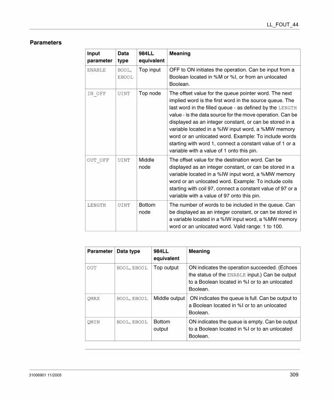
LL_FOUT_44
Parameters
Input parameter
Data type
984LL equivalent
Meaning
ENABLE BOOL, EBOOL
Top input OFF to ON initiates the operation. Can be input from a Boolean located in %M or %I, or from an unlocated Boolean.
IN_OFF UINT Top node The offset value for the queue pointer word. The next implied word is the first word in the source queue. The last word in the filled queue - as defined by the LENGTH value - is the data source for the move operation. Can be displayed as an integer constant, or can be stored in a variable located in a %IW input word, a %MW memory word or an unlocated word. Example: To include words starting with word 1, connect a constant value of 1 or a variable with a value of 1 onto this pin.
OUT_OFF UINT Middle node
The offset value for the destination word. Can be displayed as an integer constant, or can be stored in a variable located in a %IW input word, a %MW memory word or an unlocated word. Example: To include coils starting with coil 97, connect a constant value of 97 or a variable with a value of 97 onto this pin.
LENGTH UINT Bottom node
The number of words to be included in the queue. Can be displayed as an integer constant, or can be stored in a variable located in a %IW input word, a %MW memory word or an unlocated word. Valid range: 1 to 100.
Parameter Data type 984LL equivalent
Meaning
OUT BOOL, EBOOL Top output ON indicates the operation succeeded. (Echoes the status of the ENABLE input.) Can be output to a Boolean located in %I or to an unlocated Boolean.
QMAX BOOL, EBOOL Middle output ON indicates the queue is full. Can be output to a Boolean located in %I or to an unlocated Boolean.
QMIN BOOL, EBOOL Bottom output
ON indicates the queue is empty. Can be output to a Boolean located in %I or to an unlocated Boolean.
31006901 11/2005 309

LL_FOUT_44
310 31006901 11/2005

31006901 11/2005
75
LL_R_TO_T_04: Register to Table (%M - %MW)Description
Function Description
The LL_R_TO_T_04 instruction copies the bit pattern of a 16-bit Boolean sequence located in %M memory to a word located in a table in %MW memory. It can overwrite the contents of 1 word per scan until every word in the destination table has been overwritten.
The LENGTH value indicates the number of words in the destination table. The IN_OFF offset value defines the location of the first bit in the source 16-bit Boolean sequence. The OUT_OFF offset value defines the location of the destination table’s pointer. The pointer’s value indicates the number of words in the destination table that the operation has overwritten, and points to the next word the operation will overwrite. The word contiguous to and following the pointer is the first word in the destination table.
The operation begins when the input to the ENABLE pin is turned ON. If both the FREEZE and RESET inputs remain OFF during operation, the pointer will increment by a value of 1 after each scan, causing the operation to move to the next adjacent word within the destination table.
The operation continues to copy source data to the next contiguous word until the operation reaches the end of the table, or until either of the following events occurs. If the FREEZE input turns ON, the pointer stops incrementing and the operation continues to overwrite the same destination word. If the RESET input turns ON, the pointer is reset to 0, and the operation moves to the first word in the destination table.
The OUT output turns ON upon the successful completion of the operation. The PTR_END output turns ON if the pointer’s value equals the LENGTH value, indicating the end of the table has been reached and no additional source data can be written to the table.
EN and ENO can be configured as additional parameters.
311

LL_R_TO_T_04
Representation in FBD
Representation in LD
Representation in IL
CAL LL_R_TO_T_04_Instance (ENABLE:=Trigger, FREEZE:=StopIncrement, RESET:=ZeroIncrement, IN_OFF:=Source, OUT_OFF:=Destination, LENGTH:=Integer1, OUT=>Success, PTR_END=>Filled)
Representation in ST
LL_R_TO_T_04_Instance (ENABLE:=Trigger, FREEZE:=StopIncrement, RESET:=ZeroIncrement, IN_OFF:=Source, OUT_OFF:=Destination, LENGTH:=Integer1, OUT=>Success, PTR_END=>Filled);
LL_R_TO_T_04
TriggerStopIncrement
LL_R_TO_T_04_Instance
OUTENABLEFREEZERESETIN_OFF
ZeroIncrementSource
SuccessPTR_END Filled
OUT_OFFDestinationLENGTHInteger1
Trigger
Source
ENOENSuccess
LL_R_TO_T_04LL_R_TO_T_04_Instance
OUTENABLE
IN_OFF
OUT_OFF
LENGTH
Destination
Integer1
FilledPTR_END
ZeroIncrementRESET
StopIncrementFREEZE
312 31006901 11/2005
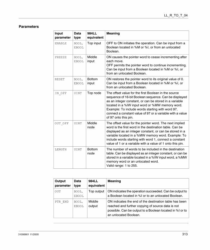
LL_R_TO_T_04
Parameters
Input parameter
Data type
984LL equivalent
Meaning
ENABLE BOOL, EBOOL
Top input OFF to ON initiates the operation. Can be input from a Boolean located in %M or %I, or from an unlocated Boolean.
FREEZE BOOL, EBOOL
Middle input
ON causes the pointer word to cease incrementing after each move. OFF permits the pointer word to continue incrementing. Can be input from a Boolean located in %M or %I, or from an unlocated Boolean.
RESET BOOL, EBOOL
Bottom input
ON restores the pointer word to its original value of 0. Can be input from a Boolean located in %M or %I, or from an unlocated Boolean.
IN_OFF UINT Top node The offset value for the first Boolean in the source sequence of 16-bit Boolean sequence. Can be displayed as an integer constant, or can be stored in a variable located in a %IW input word or %MW memory word. Example: To include words starting with word 97, connect a constant value of 97 or a variable with a value of 97 onto this pin.
OUT_OFF UINT Middle node
The offset value for the pointer word. The next implied word is the first word in the destination table. Can be displayed as an integer constant, or can be stored in a variable located in a %MW memory word. Example: To include words starting with word 1, connect a constant value of 1 or a variable with a value of 1 onto this pin.
LENGTH UINT Bottom node
The number of words to be included in the destination table. Can be displayed as an integer constant, or can be stored in a variable located in a %IW input word, a %MW memory word or an unlocated word. Valid range: 1 to 255.
Output parameter
Data type
984LL equivalent
Meaning
OUT BOOL, EBOOL
Top output ON indicates the operation succeeded. Can be output to a Boolean located in %I or to an unlocated Boolean.
PTR_END BOOL, EBOOL
Middle output
ON indicates the end of the destination table has been reached and further copying of source data is not possible. Can be output to a Boolean located in %I or to an unlocated Boolean.
31006901 11/2005 313

LL_R_TO_T_04
314 31006901 11/2005
31006901 11/2005
76
LL_R_TO_T_14: Register to Table (%I - %MW)Description
Function Description
The LL_R_TO_T_14 instruction copies the bit pattern of a 16-bit Boolean sequence of %I inputs to a word located in a table in %MW memory. It can overwrite the contents of 1 word per scan until every word in the destination table has been overwritten.
The LENGTH value indicates the number of words in the destination table. The IN_OFF offset value defines the address of the first bit in the source 16-bit Boolean sequence. The OUT_OFF offset value defines the location of the destination table’s pointer. The pointer’s value indicates the number of words in the destination table that the operation has overwritten, and points to the next word the operation will overwrite. The word contiguous to and following the pointer is the first word in the destination table.
The operation begins when the input to the ENABLE pin is turned ON. If both the FREEZE and RESET inputs remain OFF during operation, the pointer will increment by a value of 1 after each scan, causing the operation to move to the next adjacent word within the destination table.
The operation continues to copy source data to the next contiguous word until the operation reaches the end of the table, or until either of the following events occurs. If the FREEZE input turns ON, the pointer stops incrementing and the operation continues to overwrite the same destination word. If the RESET input turns ON, the pointer is reset to 0, and the operation moves to the first word in the destination table.
The OUT output turns ON upon the successful completion of the operation. The PTR_END output turns ON if the pointer’s value equals the LENGTH value, indicating the end of the table has been reached and no additional source data can be written to the table.
EN and ENO can be configured as additional parameters.
315

LL_R_TO_T_14
Representation in FBD
Representation in LD
Representation in IL
CAL LL_R_TO_T_14_Instance (ENABLE:=Trigger, FREEZE:=StopIncrement, RESET:=ZeroIncrement, IN_OFF:=Source, OUT_OFF:=Destination, LENGTH:=Integer1, OUT=>Success, PTR_END=>Filled)
Representation in ST
LL_R_TO_T_14_Instance (ENABLE:=Trigger, FREEZE:=StopIncrement, RESET:=ZeroIncrement, IN_OFF:=Source, OUT_OFF:=Destination, LENGTH:=Integer1, OUT=>Success, PTR_END=>Filled);
LL_R_TO_T_14
TriggerStopIncrement
LL_R_TO_T_14_Instance
OUTENABLEFREEZERESETIN_OFF
ZeroIncrementSource
SuccessPTR_END Filled
OUT_OFFDestinationLENGTHInteger1
Trigger
Source
ENOENSuccess
LL_R_TO_T_14LL_R_TO_T_14_Instance
OUTENABLE
IN_OFF
OUT_OFF
LENGTH
Destination
Integer1
FilledPTR_END
ZeroIncrementRESET
StopIncrementFREEZE
316 31006901 11/2005
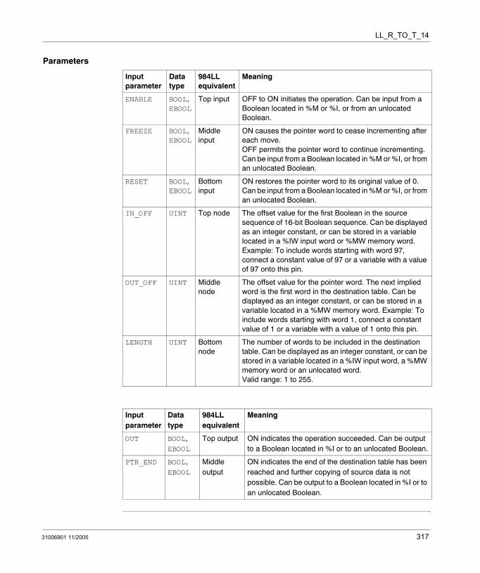
LL_R_TO_T_14
Parameters
Input parameter
Data type
984LL equivalent
Meaning
ENABLE BOOL, EBOOL
Top input OFF to ON initiates the operation. Can be input from a Boolean located in %M or %I, or from an unlocated Boolean.
FREEZE BOOL, EBOOL
Middle input
ON causes the pointer word to cease incrementing after each move. OFF permits the pointer word to continue incrementing. Can be input from a Boolean located in %M or %I, or from an unlocated Boolean.
RESET BOOL, EBOOL
Bottom input
ON restores the pointer word to its original value of 0. Can be input from a Boolean located in %M or %I, or from an unlocated Boolean.
IN_OFF UINT Top node The offset value for the first Boolean in the source sequence of 16-bit Boolean sequence. Can be displayed as an integer constant, or can be stored in a variable located in a %IW input word or %MW memory word. Example: To include words starting with word 97, connect a constant value of 97 or a variable with a value of 97 onto this pin.
OUT_OFF UINT Middle node
The offset value for the pointer word. The next implied word is the first word in the destination table. Can be displayed as an integer constant, or can be stored in a variable located in a %MW memory word. Example: To include words starting with word 1, connect a constant value of 1 or a variable with a value of 1 onto this pin.
LENGTH UINT Bottom node
The number of words to be included in the destination table. Can be displayed as an integer constant, or can be stored in a variable located in a %IW input word, a %MW memory word or an unlocated word. Valid range: 1 to 255.
Input parameter
Data type
984LL equivalent
Meaning
OUT BOOL, EBOOL
Top output ON indicates the operation succeeded. Can be output to a Boolean located in %I or to an unlocated Boolean.
PTR_END BOOL, EBOOL
Middle output
ON indicates the end of the destination table has been reached and further copying of source data is not possible. Can be output to a Boolean located in %I or to an unlocated Boolean.
31006901 11/2005 317

LL_R_TO_T_14
318 31006901 11/2005
31006901 11/2005
77
LL_R_TO_T_34: Register to Table (%IW - %MW)Description
Function Description
The LL_R_TO_T_34 instruction copies the bit pattern of a %IW input word to a word located in a table in %MW memory. It can overwrite the contents of 1 word per scan until every word in the destination table has been overwritten.
The LENGTH value indicates the number of words in the destination table. The IN_OFF offset value defines the address of the source word. The OUT_OFF offset value defines the location of the destination table’s pointer. The pointer’s value indicates the number of words in the destination table that the operation has overwritten, and points to the next word the operation will overwrite. The word contiguous to and following the pointer is the first word in the destination table.
The operation begins when the input to the ENABLE pin is turned ON. If both the FREEZE and RESET inputs remain OFF during operation, the pointer will increment by a value of 1 after each scan, causing the operation to move to the next adjacent word within the destination table.
The operation continues to copy source data to the next contiguous word until the operation reaches the end of the table, or until either of the following events occurs. If the FREEZE input turns ON, the pointer stops incrementing and the operation continues to overwrite the same destination word. If the RESET input turns ON, the pointer is reset to 0, and the operation moves to the first word in the destination table.
The OUT output turns ON upon the successful completion of the operation. The PTR_END output turns ON if the pointer’s value equals the LENGTH value, indicating the end of the table has been reached and no additional source data can be written to the table.
EN and ENO can be configured as additional parameters.
319

LL_R_TO_T_34
Representation in FBD
Representation in LD
Representation in IL
CAL LL_R_TO_T_34_Instance (ENABLE:=Trigger, FREEZE:=StopIncrement, RESET:=ZeroIncrement, IN_OFF:=Source, OUT_OFF:=Destination, LENGTH:=Integer1, OUT=>Success, PTR_END=>Filled)
Representation in ST
LL_R_TO_T_34_Instance (ENABLE:=Trigger, FREEZE:=StopIncrement, RESET:=ZeroIncrement, IN_OFF:=Source, OUT_OFF:=Destination, LENGTH:=Integer1, OUT=>Success, PTR_END=>Filled);
LL_R_TO_T_34
TriggerStopIncrement
LL_R_TO_T_34_Instance
OUTENABLEFREEZERESETIN_OFF
ZeroIncrementSource
SuccessPTR_END Filled
OUT_OFFDestinationLENGTHInteger1
Trigger
Source
ENOENSuccess
LL_R_TO_T_34LL_R_TO_T_34_Instance
OUTENABLE
IN_OFF
OUT_OFF
LENGTH
Destination
Integer1
FilledPTR_END
ZeroIncrementRESET
StopIncrementFREEZE
320 31006901 11/2005
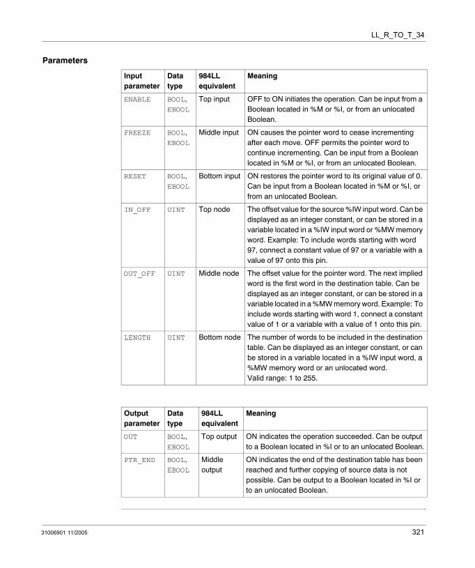
LL_R_TO_T_34
Parameters
Input parameter
Data type
984LL equivalent
Meaning
ENABLE BOOL, EBOOL
Top input OFF to ON initiates the operation. Can be input from a Boolean located in %M or %I, or from an unlocated Boolean.
FREEZE BOOL, EBOOL
Middle input ON causes the pointer word to cease incrementing after each move. OFF permits the pointer word to continue incrementing. Can be input from a Boolean located in %M or %I, or from an unlocated Boolean.
RESET BOOL, EBOOL
Bottom input ON restores the pointer word to its original value of 0. Can be input from a Boolean located in %M or %I, or from an unlocated Boolean.
IN_OFF UINT Top node The offset value for the source %IW input word. Can be displayed as an integer constant, or can be stored in a variable located in a %IW input word or %MW memory word. Example: To include words starting with word 97, connect a constant value of 97 or a variable with a value of 97 onto this pin.
OUT_OFF UINT Middle node The offset value for the pointer word. The next implied word is the first word in the destination table. Can be displayed as an integer constant, or can be stored in a variable located in a %MW memory word. Example: To include words starting with word 1, connect a constant value of 1 or a variable with a value of 1 onto this pin.
LENGTH UINT Bottom node The number of words to be included in the destination table. Can be displayed as an integer constant, or can be stored in a variable located in a %IW input word, a %MW memory word or an unlocated word. Valid range: 1 to 255.
Output parameter
Data type
984LL equivalent
Meaning
OUT BOOL, EBOOL
Top output ON indicates the operation succeeded. Can be output to a Boolean located in %I or to an unlocated Boolean.
PTR_END BOOL, EBOOL
Middle output
ON indicates the end of the destination table has been reached and further copying of source data is not possible. Can be output to a Boolean located in %I or to an unlocated Boolean.
31006901 11/2005 321

LL_R_TO_T_34
322 31006901 11/2005
31006901 11/2005
78
LL_R_TO_T_44: Register to Table (%MW - %MW)Description
Function Description
The LL_R_TO_T_44 instruction copies the bit pattern of a word located in %MW memory to a word in a table also located in %MW memory. It can overwrite the contents of 1 word per scan until every word in the destination table has been overwritten.
The LENGTH value indicates the number of words in the destination table. The IN_OFF offset value defines the location of the source word. The OUT_OFF offset value defines the location of the destination table’s pointer. The pointer’s value indicates the number of words in the destination table that the operation has overwritten, and points to the next word the operation will overwrite. The word contiguous to and following the pointer is the first word in the destination table.
The operation begins when the input to the ENABLE pin is turned ON. If both the FREEZE and RESET inputs remain OFF during operation, the pointer will increment by a value of 1 after each scan, causing the operation to move to the next adjacent word within the destination table.
The operation continues to copy source data to the next contiguous word until the operation reaches the end of the table, or until either of the following events occurs. If the FREEZE input turns ON, the pointer stops incrementing and the operation continues to overwrite the same destination word. If the RESET input turns ON, the pointer is reset to 0, and the operation moves to the first word in the destination table.
The OUT output turns ON upon the successful completion of the operation. The PTR_END output turns ON if the pointer’s value equals the LENGTH value, indicating the end of the table has been reached and no additional source data can be written to the table.
EN and ENO can be configured as additional parameters.
323

LL_R_TO_T_44
Representation in FBD
Representation in LD
Representation in IL
CAL LL_R_TO_T_44_Instance (ENABLE:=Trigger, FREEZE:=StopIncrement, RESET:=ZeroIncrement, IN_OFF:=Source, OUT_OFF:=Destination, LENGTH:=Integer1, OUT=>Success, PTR_END=>Filled)
Representation in ST
LL_R_TO_T_44_Instance (ENABLE:=Trigger, FREEZE:=StopIncrement, RESET:=ZeroIncrement, IN_OFF:=Source, OUT_OFF:=Destination, LENGTH:=Integer1, OUT=>Success, PTR_END=>Filled);
LL_R_TO_T_44
TriggerStopIncrement
LL_R_TO_T_44_Instance
OUTENABLEFREEZERESETIN_OFF
ZeroIncrementSource
SuccessPTR_END Filled
OUT_OFFDestinationLENGTHInteger1
Trigger
Source
ENOENSuccess
LL_R_TO_T_44LL_R_TO_T_44_Instance
OUTENABLE
IN_OFF
OUT_OFF
LENGTH
Destination
Integer1
FilledPTR_END
ZeroIncrementRESET
StopIncrementFREEZE
324 31006901 11/2005
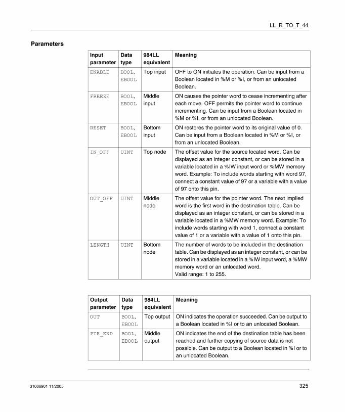
LL_R_TO_T_44
Parameters
Input parameter
Data type
984LL equivalent
Meaning
ENABLE BOOL, EBOOL
Top input OFF to ON initiates the operation. Can be input from a Boolean located in %M or %I, or from an unlocated Boolean.
FREEZE BOOL, EBOOL
Middle input
ON causes the pointer word to cease incrementing after each move. OFF permits the pointer word to continue incrementing. Can be input from a Boolean located in %M or %I, or from an unlocated Boolean.
RESET BOOL, EBOOL
Bottom input
ON restores the pointer word to its original value of 0. Can be input from a Boolean located in %M or %I, or from an unlocated Boolean.
IN_OFF UINT Top node The offset value for the source located word. Can be displayed as an integer constant, or can be stored in a variable located in a %IW input word or %MW memory word. Example: To include words starting with word 97, connect a constant value of 97 or a variable with a value of 97 onto this pin.
OUT_OFF UINT Middle node
The offset value for the pointer word. The next implied word is the first word in the destination table. Can be displayed as an integer constant, or can be stored in a variable located in a %MW memory word. Example: To include words starting with word 1, connect a constant value of 1 or a variable with a value of 1 onto this pin.
LENGTH UINT Bottom node
The number of words to be included in the destination table. Can be displayed as an integer constant, or can be stored in a variable located in a %IW input word, a %MW memory word or an unlocated word. Valid range: 1 to 255.
Output parameter
Data type
984LL equivalent
Meaning
OUT BOOL, EBOOL
Top output ON indicates the operation succeeded. Can be output to a Boolean located in %I or to an unlocated Boolean.
PTR_END BOOL, EBOOL
Middle output
ON indicates the end of the destination table has been reached and further copying of source data is not possible. Can be output to a Boolean located in %I or to an unlocated Boolean.
31006901 11/2005 325

LL_R_TO_T_44
326 31006901 11/2005
31006901 11/2005
79
LL_T_TO_R_04: Table to Register (%M - %MW)Description
Function Description
The LL_T_TO_R_04 instruction copies the bit pattern of a 16-bit Boolean sequence in a table located in %M memory to a destination word located in %MW memory. It can write the bit pattern of 1 16-bit Boolean sequence per scan until the bit pattern of every 16-bit Boolean sequence in the source table has been written to the destination word.
The LENGTH value indicates the number of 16-bit Boolean sequences in the source table. The IN_OFF offset value defines the location of the first bit in the 16-bit Boolean sequence that constitutes the table pointer. The pointer value indicates the number of 16-bit Boolean sequences in the source table that the operation has copied and written to the destination word, and points to the next 16-bit Boolean sequence the operation will copy and write. The 16-bit Boolean sequence that is contiguous to and follows the pointer is the first 16-bit Boolean sequence in the source table. The OUT_OFF offset value defines the location of the destination word.
The operation begins when the input to the ENABLE pin is turned ON. If both the FREEZE and RESET inputs remain OFF during operation, the pointer will increment by a value of 1 after each scan, causing the operation to move to and write from the next adjacent 16-bit Boolean sequence within the source table.
The operation continues to copy source data to the destination word from the next contiguous 16-bit Boolean sequence until the operation reaches the end of the table, or until either of the following events occurs. If the FREEZE input turns ON, the pointer stops incrementing and the operation continues to write from the same 16-bit Boolean sequence. If the RESET input turns ON, the pointer is reset to 0, and the operation moves to and writes from the first 16-bit Boolean sequence in the source table.
The OUT output turns ON upon the successful completion of the operation. The PTR_END output turns ON if the pointer value equals the LENGTH value, indicating the end of the table has been reached and no additional source data can be written from the table.
EN and ENO can be configured as additional parameters.
327

LL_T_TO_R_04
Representation in FBD
Representation in LD
Representation in IL
CAL LL_T_TO_R_04_Instance (ENABLE:=Trigger, FREEZE:=StopIncrement, RESET:=ZeroIncrement, IN_OFF:=Source, OUT_OFF:=Destination, LENGTH:=Integer1, OUT=>Success, PTR_END=>Filled)
Representation in ST
LL_T_TO_R_04_Instance (ENABLE:=Trigger, FREEZE:=StopIncrement, RESET:=ZeroIncrement, IN_OFF:=Source, OUT_OFF:=Destination, LENGTH:=Integer1, OUT=>Success, PTR_END=>Filled);
LL_T_TO_R_04
TriggerStopIncrement
LL_T_TO_R_04_Instance
OUTENABLEFREEZERESETIN_OFF
ZeroIncrementSource
SuccessPTR_END Filled
OUT_OFFDestinationLENGTHInteger1
Trigger
Source
ENOENSuccess
LL_T_TO_R_04LL_T_TO_R_04_Instance
OUTENABLE
IN_OFF
OUT_OFF
LENGTH
Destination
Integer1
FilledPTR_END
ZeroIncrementRESET
StopIncrementFREEZE
328 31006901 11/2005

LL_T_TO_R_04
Parameters
Input parameter
Data type
984LL equivalent
Meaning
ENABLE BOOL, EBOOL
Top input OFF to ON initiates the operation. Can be input from a Boolean located in %M or %I, or from an unlocated Boolean.
FREEZE BOOL, EBOOL
Middle input
ON causes the pointer to cease incrementing after each move. OFF permits the pointer to continue incrementing. Can be input from a Boolean located in %M or %I, or from an unlocated Boolean.
RESET BOOL, EBOOL
Bottom input
ON restores the pointer to its original value of 0. Can be input from a Boolean located in %M or %I, or from an unlocated Boolean.
IN_OFF UINT Top node The offset value for the first Boolean in the pointer sequence of 16-bit Boolean sequence. The next 16-bit Boolean sequence is the first sequence in the source table. Can be displayed as an integer constant, or can be stored in a variable located in a %MW memory word. Example: To include coils starting with coil 1, connect a constant value of 1 or a variable with a value of 1 onto this pin.
OUT_OFF UINT Middle node
The offset value for the destination word. Can be displayed as an integer constant, or can be stored in a variable located in a %IW input word or %MW memory word. Example: To include words starting with word 97, connect a constant value of 97 or a variable with a value of 97 onto this pin
LENGTH UINT Bottom node
The number of 16-bit Boolean sequences included in the source table. Can be displayed as an integer constant, or can be stored in a variable located in a %IW input word, a %MW memory word or an unlocated word. Valid range: 1 to 255.
Output parameter
Data type
984LL equivalent
Meaning
OUT BOOL, EBOOL
Top output ON indicates the operation succeeded. Can be output to a Boolean located in %I or to an unlocated Boolean.
PTR_END BOOL, EBOOL
Middle output
ON indicates the end of the source table has been reached and further writing form the source table is not possible. Can be output to a Boolean located in %I or to an unlocated Boolean.
31006901 11/2005 329

LL_T_TO_R_04
330 31006901 11/2005

31006901 11/2005
80
LL_T_TO_R_14: Table to Register (%I - %MW)Description
Function Description
The LL_T_TO_R_14 instruction copies the bit pattern of a 16-bit Boolean sequence in a table composed of %I inputs to a destination word located in %MW memory. It can write the bit pattern of 1 16-bit Boolean sequence per scan until the bit pattern of every 16-bit Boolean sequence in the source table has been written to the destination word.
The LENGTH value indicates the number of 16-bit Boolean sequences in the source table. The IN_OFF offset value defines the location of the first bit in a 16-bit Boolean sequence that constitutes the table pointer. The pointer value indicates the number of 16-bit Boolean sequences in the source table that the operation has copied and written to the destination word, and points to the next 16-bit Boolean sequence the operation will copy and write. The 16-bit Boolean sequence that is contiguous to and follows the pointer is the first 16-bit Boolean sequence in the source table. The OUT_OFF offset value defines the location of the destination word.
The operation begins when the input to the ENABLE pin is turned ON. If both the FREEZE and RESET inputs remain OFF during operation, the pointer will increment by a value of 1 after each scan, causing the operation to move to and write from the next adjacent 16-bit Boolean sequence within the source table.
The operation continues to copy source data to the destination word from the next contiguous 16-bit Boolean sequence until the operation reaches the end of the table, or until either of the following events occurs. If the FREEZE input turns ON, the pointer stops incrementing and the operation continues to write from the same 16-bit Boolean sequence. If the RESET input turns ON, the pointer is reset to 0, and the operation moves to and writes from the first 16-bit Boolean sequence in the source table.
The OUT output turns ON upon the successful completion of the operation. The PTR_END output turns ON if the pointer value equals the LENGTH value, indicating the end of the table has been reached and no additional source data can be written from the table.
EN and ENO can be configured as additional parameters.
331

LL_T_TO_R_14
Representation in FBD
Representation in LD
Representation in IL
CAL LL_T_TO_R_14_Instance (ENABLE:=Trigger, FREEZE:=StopIncrement, RESET:=ZeroIncrement, IN_OFF:=Source, OUT_OFF:=Destination, LENGTH:=Integer1, OUT=>Success, PTR_END=>Filled)
Representation in ST
LL_T_TO_R_14_Instance (ENABLE:=Trigger, FREEZE:=StopIncrement, RESET:=ZeroIncrement, IN_OFF:=Source, OUT_OFF:=Destination, LENGTH:=Integer1, OUT=>Success, PTR_END=>Filled);
LL_T_TO_R_14
TriggerStopIncrement
LL_T_TO_R_14_Instance
OUTENABLEFREEZERESETIN_OFF
ZeroIncrementSource
SuccessPTR_END Filled
OUT_OFFDestinationLENGTHInteger1
Trigger
Source
ENOENSuccess
LL_T_TO_R_14LL_T_TO_R_14_Instance
OUTENABLE
IN_OFF
OUT_OFF
LENGTH
Destination
Integer1
FilledPTR_END
ZeroIncrementRESET
StopIncrementFREEZE
332 31006901 11/2005
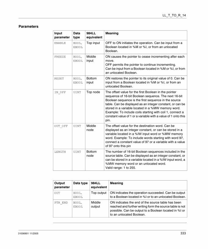
LL_T_TO_R_14
Parameters
Input parameter
Data type
984LL equivalent
Meaning
ENABLE BOOL, EBOOL
Top input OFF to ON initiates the operation. Can be input from a Boolean located in %M or %I, or from an unlocated Boolean.
FREEZE BOOL, EBOOL
Middle input
ON causes the pointer to cease incrementing after each move. OFF permits the pointer to continue incrementing. Can be input from a Boolean located in %M or %I, or from an unlocated Boolean.
RESET BOOL, EBOOL
Bottom input
ON restores the pointer to its original value of 0. Can be input from a Boolean located in %M or %I, or from an unlocated Boolean.
IN_OFF UINT Top node The offset value for the first Boolean in the pointer sequence of 16-bit Boolean sequence. The next 16-bit Boolean sequence is the first sequence in the source table. Can be displayed as an integer constant, or can be stored in a variable located in a %MW memory word. Example: To include coils starting with coil 1, connect a constant value of 1 or a variable with a value of 1 onto this pin.
OUT_OFF UINT Middle node
The offset value for the destination word. Can be displayed as an integer constant, or can be stored in a variable located in a %IW input word or %MW memory word. Example: To include words starting with word 97, connect a constant value of 97 or a variable with a value of 97 onto this pin
LENGTH UINT Bottom node
The number of 16-bit Boolean sequences included in the source table. Can be displayed as an integer constant, or can be stored in a variable located in a %IW input word, a %MW memory word or an unlocated word. Valid range: 1 to 255.
Output parameter
Data type 984LL equivalent
Meaning
OUT BOOL, EBOOL
Top output ON indicates the operation succeeded. Can be output to a Boolean located in %I or to an unlocated Boolean.
PTR_END BOOL, EBOOL
Middle output
ON indicates the end of the source table has been reached and further writing form the source table is not possible. Can be output to a Boolean located in %I or to an unlocated Boolean.
31006901 11/2005 333

LL_T_TO_R_14
334 31006901 11/2005
31006901 11/2005
81
LL_T_TO_R_34: Table to Register (%IW - %MW)Description
Function Description
The LL_T_TO_R_34 instruction copies the bit pattern of a word in a table of %IW input words to a word located in %MW memory. It can write the bit pattern of 1 source word per scan until the bit pattern of every word in the source table has been written to the destination word.
The LENGTH value indicates the number of words in the source table. The IN_OFF offset value defines the location of the pointer. The pointer value indicates the number of words in the source table that the operation has copied and written to the destination word, and points to the next word the operation will copy and write. The word that is contiguous to and follows the pointer is the first word in the source table. The OUT_OFF offset value defines the location of the destination word.
The operation begins when the input to the ENABLE pin is turned ON. If both the FREEZE and RESET inputs remain OFF during operation, the pointer will increment by a value of 1 after each scan, causing the operation to move to and write from the next adjacent word within the source table.
The operation continues to copy source data to the destination word from the next contiguous source word until the operation reaches the end of the table, or until either of the following events occurs. If the FREEZE input turns ON, the pointer stops incrementing and the operation continues to write from the same source word. If the RESET input turns ON, the pointer is reset to 0, and the operation moves to and writes from the first word in the source table.
The OUT output turns ON upon the successful completion of the operation. The PTR_END output turns ON if the pointer value equals the LENGTH value, indicating the end of the table has been reached and no additional source data can be written from the table.
EN and ENO can be configured as additional parameters.
335

LL_T_TO_R_34
Representation in FBD
Representation in LD
Representation in IL
CAL LL_T_TO_R_34_Instance (ENABLE:=Trigger, FREEZE:=StopIncrement, RESET:=ZeroIncrement, IN_OFF:=Source, OUT_OFF:=Destination, LENGTH:=Integer1, OUT=>Success, PTR_END=>Filled)
Representation in ST
LL_T_TO_R_34_Instance (ENABLE:=Trigger, FREEZE:=StopIncrement, RESET:=ZeroIncrement, IN_OFF:=Source, OUT_OFF:=Destination, LENGTH:=Integer1, OUT=>Success, PTR_END=>Filled);
LL_T_TO_R_34
TriggerStopIncrement
LL_T_TO_R_34_Instance
OUTENABLEFREEZERESETIN_OFF
ZeroIncrementSource
SuccessPTR_END Filled
OUT_OFFDestinationLENGTHInteger1
Trigger
Source
ENOENSuccess
LL_T_TO_R_34LL_T_TO_R_34_Instance
OUTENABLE
IN_OFF
OUT_OFF
LENGTH
Destination
Integer1
FilledPTR_END
ZeroIncrementRESET
StopIncrementFREEZE
336 31006901 11/2005
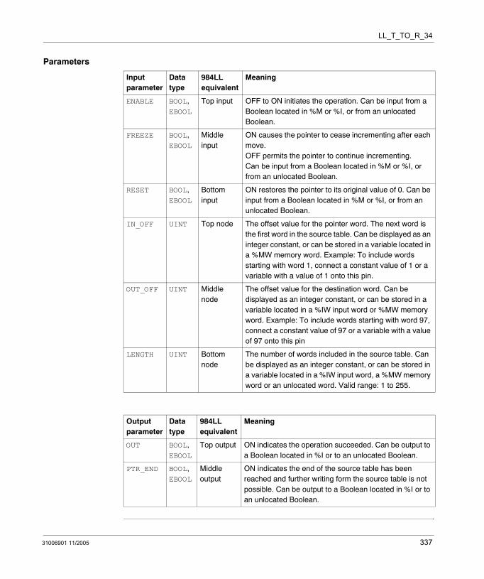
LL_T_TO_R_34
Parameters
Input parameter
Data type
984LL equivalent
Meaning
ENABLE BOOL, EBOOL
Top input OFF to ON initiates the operation. Can be input from a Boolean located in %M or %I, or from an unlocated Boolean.
FREEZE BOOL, EBOOL
Middle input
ON causes the pointer to cease incrementing after each move. OFF permits the pointer to continue incrementing. Can be input from a Boolean located in %M or %I, or from an unlocated Boolean.
RESET BOOL, EBOOL
Bottom input
ON restores the pointer to its original value of 0. Can be input from a Boolean located in %M or %I, or from an unlocated Boolean.
IN_OFF UINT Top node The offset value for the pointer word. The next word is the first word in the source table. Can be displayed as an integer constant, or can be stored in a variable located in a %MW memory word. Example: To include words starting with word 1, connect a constant value of 1 or a variable with a value of 1 onto this pin.
OUT_OFF UINT Middle node
The offset value for the destination word. Can be displayed as an integer constant, or can be stored in a variable located in a %IW input word or %MW memory word. Example: To include words starting with word 97, connect a constant value of 97 or a variable with a value of 97 onto this pin
LENGTH UINT Bottom node
The number of words included in the source table. Can be displayed as an integer constant, or can be stored in a variable located in a %IW input word, a %MW memory word or an unlocated word. Valid range: 1 to 255.
Output parameter
Data type
984LL equivalent
Meaning
OUT BOOL, EBOOL
Top output ON indicates the operation succeeded. Can be output to a Boolean located in %I or to an unlocated Boolean.
PTR_END BOOL, EBOOL
Middle output
ON indicates the end of the source table has been reached and further writing form the source table is not possible. Can be output to a Boolean located in %I or to an unlocated Boolean.
31006901 11/2005 337

LL_T_TO_R_34
338 31006901 11/2005
31006901 11/2005
82
LL_T_TO_R_44: Table to Register (%MW - %MW)Description
Function Description
The LL_T_TO_R_44 instruction copies the bit pattern of a word in a table of %MW located words to a destination word located in %MW memory. It can write the bit pattern of 1 source word per scan until the bit pattern of every word in the source table has been written to the destination word.
The LENGTH value indicates the number of words in the source table. The IN_OFF offset value defines the location of the pointer. The pointer value indicates the number of words in the source table that the operation has copied and written to the destination word, and points to the next word the operation will copy and write. The word that is contiguous to and follows the pointer is the first word in the source table. The OUT_OFF offset value defines the location of the destination word.
The operation begins when the input to the ENABLE pin is turned ON. If both the FREEZE and RESET inputs remain OFF during operation, the pointer will increment by a value of 1 after each scan, causing the operation to move to and write from the next adjacent word within the source table.
The operation continues to copy source data to the destination word from the next contiguous source word until the operation reaches the end of the table, or until either of the following events occurs. If the FREEZE input turns ON, the pointer stops incrementing and the operation continues to write from the same source word. If the RESET input turns ON, the pointer is reset to 0, and the operation moves to and writes from the first word in the source table.
The OUT output turns ON upon the successful completion of the operation. The PTR_END output turns ON if the pointer value equals the LENGTH value, indicating the end of the table has been reached and no additional source data can be written from the table.
EN and ENO can be configured as additional parameters.
339
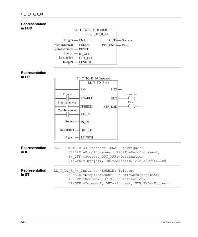
LL_T_TO_R_44
Representation in FBD
Representation in LD
Representation in IL
CAL LL_T_TO_R_44_Instance (ENABLE:=Trigger, FREEZE:=StopIncrement, RESET:=ZeroIncrement, IN_OFF:=Source, OUT_OFF:=Destination, LENGTH:=Integer1, OUT=>Success, PTR_END=>Filled)
Representation in ST
LL_T_TO_R_44_Instance (ENABLE:=Trigger, FREEZE:=StopIncrement, RESET:=ZeroIncrement, IN_OFF:=Source, OUT_OFF:=Destination, LENGTH:=Integer1, OUT=>Success, PTR_END=>Filled);
LL_T_TO_R_44
TriggerStopIncrement
LL_T_TO_R_44_Instance
OUTENABLEFREEZERESETIN_OFF
ZeroIncrementSource
SuccessPTR_END Filled
OUT_OFFDestinationLENGTHInteger1
Trigger
Source
ENOENSuccess
LL_T_TO_R_44LL_T_TO_R_44_Instance
OUTENABLE
IN_OFF
OUT_OFF
LENGTH
Destination
Integer1
FilledPTR_END
ZeroIncrementRESET
StopIncrementFREEZE
340 31006901 11/2005
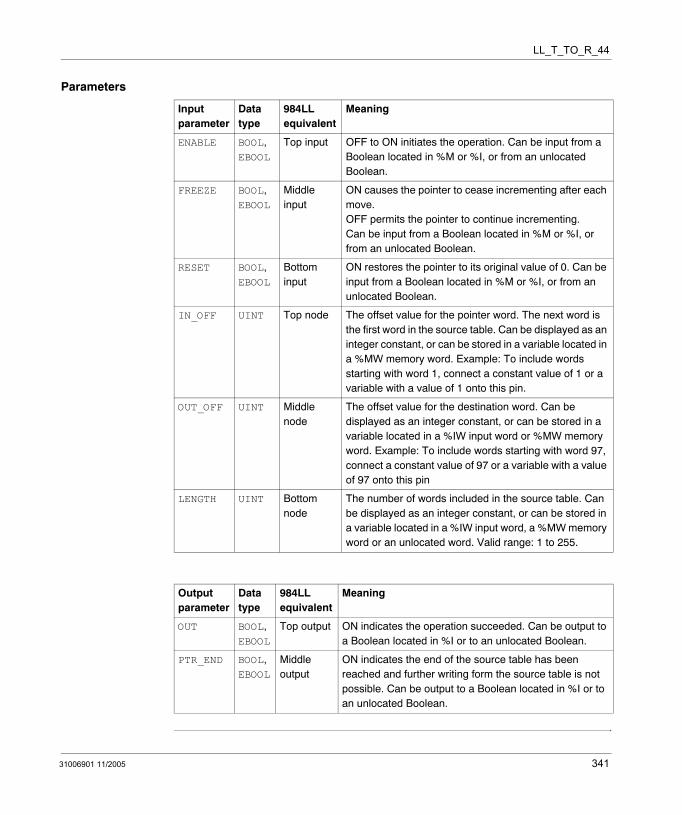
LL_T_TO_R_44
Parameters
Input parameter
Data type
984LL equivalent
Meaning
ENABLE BOOL, EBOOL
Top input OFF to ON initiates the operation. Can be input from a Boolean located in %M or %I, or from an unlocated Boolean.
FREEZE BOOL, EBOOL
Middle input
ON causes the pointer to cease incrementing after each move. OFF permits the pointer to continue incrementing. Can be input from a Boolean located in %M or %I, or from an unlocated Boolean.
RESET BOOL, EBOOL
Bottom input
ON restores the pointer to its original value of 0. Can be input from a Boolean located in %M or %I, or from an unlocated Boolean.
IN_OFF UINT Top node The offset value for the pointer word. The next word is the first word in the source table. Can be displayed as an integer constant, or can be stored in a variable located in a %MW memory word. Example: To include words starting with word 1, connect a constant value of 1 or a variable with a value of 1 onto this pin.
OUT_OFF UINT Middle node
The offset value for the destination word. Can be displayed as an integer constant, or can be stored in a variable located in a %IW input word or %MW memory word. Example: To include words starting with word 97, connect a constant value of 97 or a variable with a value of 97 onto this pin
LENGTH UINT Bottom node
The number of words included in the source table. Can be displayed as an integer constant, or can be stored in a variable located in a %IW input word, a %MW memory word or an unlocated word. Valid range: 1 to 255.
Output parameter
Data type
984LL equivalent
Meaning
OUT BOOL, EBOOL
Top output ON indicates the operation succeeded. Can be output to a Boolean located in %I or to an unlocated Boolean.
PTR_END BOOL, EBOOL
Middle output
ON indicates the end of the source table has been reached and further writing form the source table is not possible. Can be output to a Boolean located in %I or to an unlocated Boolean.
31006901 11/2005 341

LL_T_TO_R_44
342 31006901 11/2005
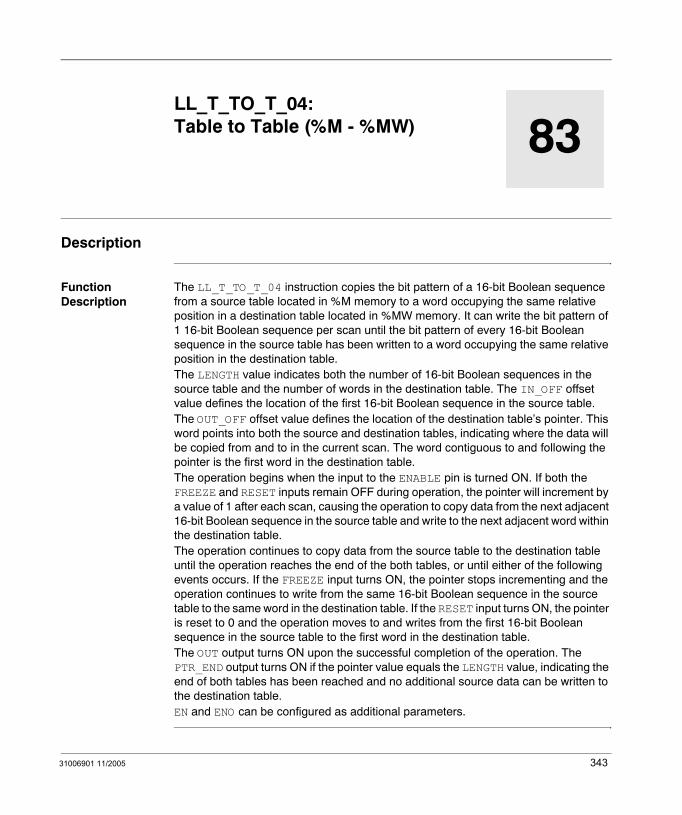
31006901 11/2005
83
LL_T_TO_T_04: Table to Table (%M - %MW)Description
Function Description
The LL_T_TO_T_04 instruction copies the bit pattern of a 16-bit Boolean sequence from a source table located in %M memory to a word occupying the same relative position in a destination table located in %MW memory. It can write the bit pattern of 1 16-bit Boolean sequence per scan until the bit pattern of every 16-bit Boolean sequence in the source table has been written to a word occupying the same relative position in the destination table.The LENGTH value indicates both the number of 16-bit Boolean sequences in the source table and the number of words in the destination table. The IN_OFF offset value defines the location of the first 16-bit Boolean sequence in the source table.The OUT_OFF offset value defines the location of the destination table’s pointer. This word points into both the source and destination tables, indicating where the data will be copied from and to in the current scan. The word contiguous to and following the pointer is the first word in the destination table.The operation begins when the input to the ENABLE pin is turned ON. If both the FREEZE and RESET inputs remain OFF during operation, the pointer will increment by a value of 1 after each scan, causing the operation to copy data from the next adjacent 16-bit Boolean sequence in the source table and write to the next adjacent word within the destination table.The operation continues to copy data from the source table to the destination table until the operation reaches the end of the both tables, or until either of the following events occurs. If the FREEZE input turns ON, the pointer stops incrementing and the operation continues to write from the same 16-bit Boolean sequence in the source table to the same word in the destination table. If the RESET input turns ON, the pointer is reset to 0 and the operation moves to and writes from the first 16-bit Boolean sequence in the source table to the first word in the destination table.The OUT output turns ON upon the successful completion of the operation. The PTR_END output turns ON if the pointer value equals the LENGTH value, indicating the end of both tables has been reached and no additional source data can be written to the destination table.EN and ENO can be configured as additional parameters.
343
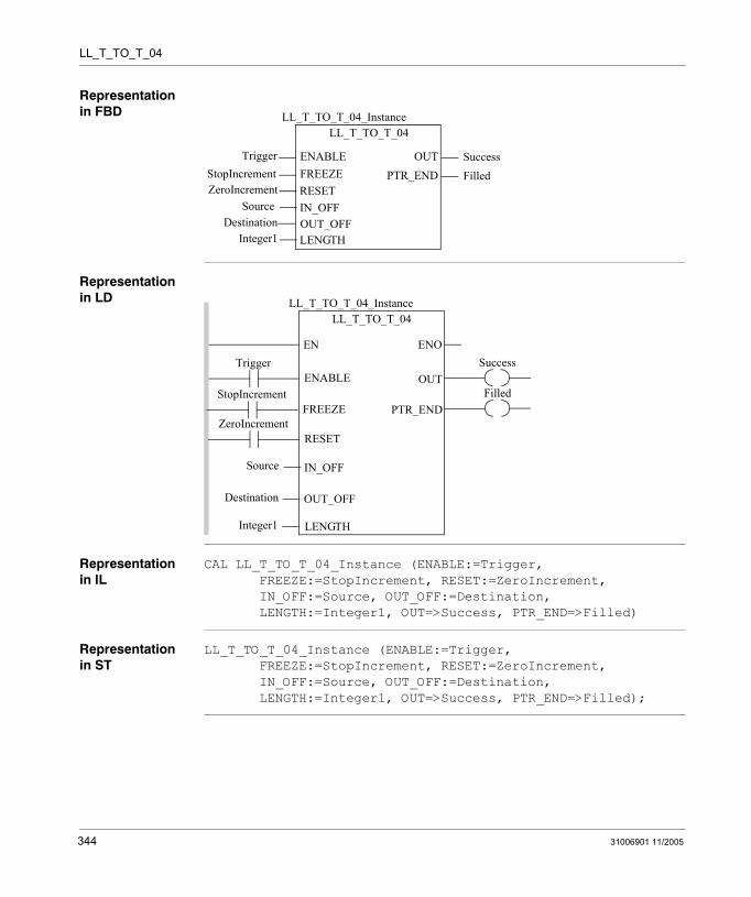
LL_T_TO_T_04
Representation in FBD
Representation in LD
Representation in IL
CAL LL_T_TO_T_04_Instance (ENABLE:=Trigger, FREEZE:=StopIncrement, RESET:=ZeroIncrement, IN_OFF:=Source, OUT_OFF:=Destination, LENGTH:=Integer1, OUT=>Success, PTR_END=>Filled)
Representation in ST
LL_T_TO_T_04_Instance (ENABLE:=Trigger, FREEZE:=StopIncrement, RESET:=ZeroIncrement, IN_OFF:=Source, OUT_OFF:=Destination, LENGTH:=Integer1, OUT=>Success, PTR_END=>Filled);
LL_T_TO_T_04
TriggerStopIncrement
LL_T_TO_T_04_Instance
OUTENABLEFREEZERESETIN_OFF
ZeroIncrementSource
SuccessPTR_END Filled
OUT_OFFDestinationLENGTHInteger1
Trigger
Source
ENOENSuccess
LL_T_TO_T_04LL_T_TO_T_04_Instance
OUTENABLE
IN_OFF
OUT_OFF
LENGTH
Destination
Integer1
FilledPTR_END
ZeroIncrementRESET
StopIncrementFREEZE
344 31006901 11/2005
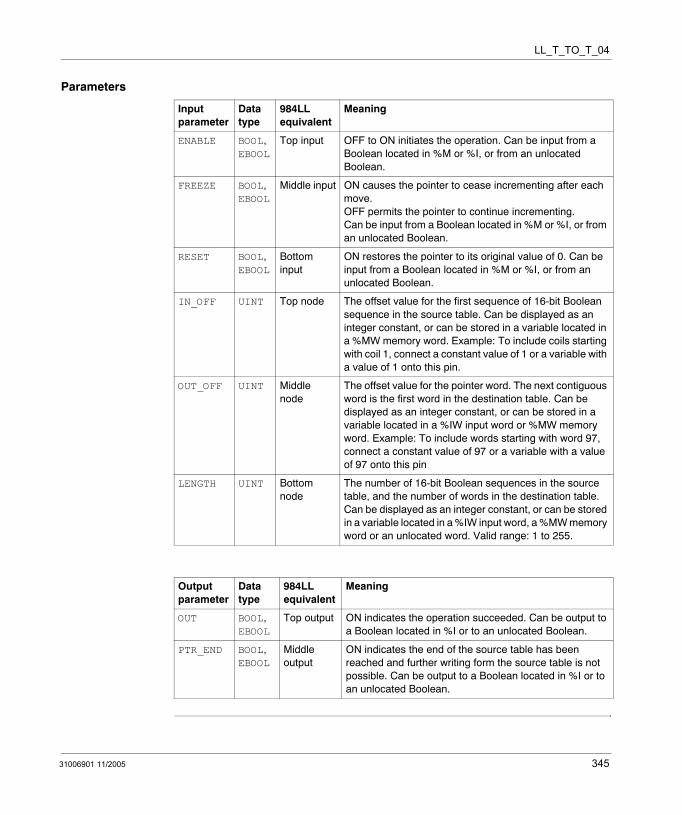
LL_T_TO_T_04
Parameters
Input parameter
Data type
984LL equivalent
Meaning
ENABLE BOOL, EBOOL
Top input OFF to ON initiates the operation. Can be input from a Boolean located in %M or %I, or from an unlocated Boolean.
FREEZE BOOL, EBOOL
Middle input ON causes the pointer to cease incrementing after each move. OFF permits the pointer to continue incrementing. Can be input from a Boolean located in %M or %I, or from an unlocated Boolean.
RESET BOOL, EBOOL
Bottom input
ON restores the pointer to its original value of 0. Can be input from a Boolean located in %M or %I, or from an unlocated Boolean.
IN_OFF UINT Top node The offset value for the first sequence of 16-bit Boolean sequence in the source table. Can be displayed as an integer constant, or can be stored in a variable located in a %MW memory word. Example: To include coils starting with coil 1, connect a constant value of 1 or a variable with a value of 1 onto this pin.
OUT_OFF UINT Middle node
The offset value for the pointer word. The next contiguous word is the first word in the destination table. Can be displayed as an integer constant, or can be stored in a variable located in a %IW input word or %MW memory word. Example: To include words starting with word 97, connect a constant value of 97 or a variable with a value of 97 onto this pin
LENGTH UINT Bottom node
The number of 16-bit Boolean sequences in the source table, and the number of words in the destination table. Can be displayed as an integer constant, or can be stored in a variable located in a %IW input word, a %MW memory word or an unlocated word. Valid range: 1 to 255.
Output parameter
Data type
984LL equivalent
Meaning
OUT BOOL, EBOOL
Top output ON indicates the operation succeeded. Can be output to a Boolean located in %I or to an unlocated Boolean.
PTR_END BOOL, EBOOL
Middle output
ON indicates the end of the source table has been reached and further writing form the source table is not possible. Can be output to a Boolean located in %I or to an unlocated Boolean.
31006901 11/2005 345

LL_T_TO_T_04
346 31006901 11/2005
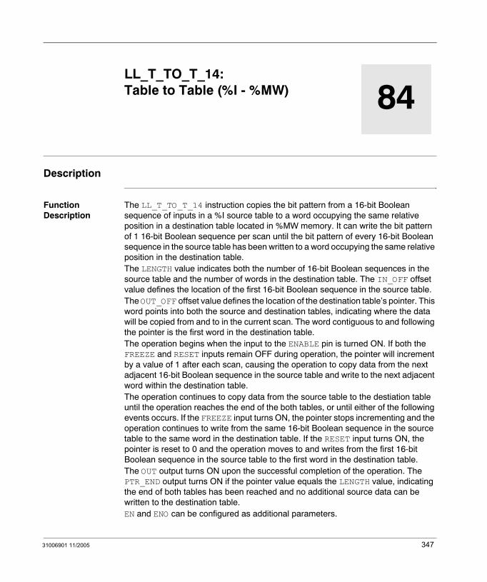
31006901 11/2005
84
LL_T_TO_T_14: Table to Table (%I - %MW)Description
Function Description
The LL_T_TO_T_14 instruction copies the bit pattern from a 16-bit Boolean sequence of inputs in a %I source table to a word occupying the same relative position in a destination table located in %MW memory. It can write the bit pattern of 1 16-bit Boolean sequence per scan until the bit pattern of every 16-bit Boolean sequence in the source table has been written to a word occupying the same relative position in the destination table.The LENGTH value indicates both the number of 16-bit Boolean sequences in the source table and the number of words in the destination table. The IN_OFF offset value defines the location of the first 16-bit Boolean sequence in the source table.The OUT_OFF offset value defines the location of the destination table’s pointer. This word points into both the source and destination tables, indicating where the data will be copied from and to in the current scan. The word contiguous to and following the pointer is the first word in the destination table.The operation begins when the input to the ENABLE pin is turned ON. If both the FREEZE and RESET inputs remain OFF during operation, the pointer will increment by a value of 1 after each scan, causing the operation to copy data from the next adjacent 16-bit Boolean sequence in the source table and write to the next adjacent word within the destination table.The operation continues to copy data from the source table to the destiation table until the operation reaches the end of the both tables, or until either of the following events occurs. If the FREEZE input turns ON, the pointer stops incrementing and the operation continues to write from the same 16-bit Boolean sequence in the source table to the same word in the destination table. If the RESET input turns ON, the pointer is reset to 0 and the operation moves to and writes from the first 16-bit Boolean sequence in the source table to the first word in the destination table.The OUT output turns ON upon the successful completion of the operation. The PTR_END output turns ON if the pointer value equals the LENGTH value, indicating the end of both tables has been reached and no additional source data can be written to the destination table.EN and ENO can be configured as additional parameters.
347

LL_T_TO_T_14
Representation in FBD
Representation in LD
Representation in IL
CAL LL_T_TO_T_14_Instance (ENABLE:=Trigger, FREEZE:=StopIncrement, RESET:=ZeroIncrement, IN_OFF:=Source, OUT_OFF:=Destination, LENGTH:=Integer1, OUT=>Success, PTR_END=>Filled)
Representation in ST
LL_T_TO_T_14_Instance (ENABLE:=Trigger, FREEZE:=StopIncrement, RESET:=ZeroIncrement, IN_OFF:=Source, OUT_OFF:=Destination, LENGTH:=Integer1, OUT=>Success, PTR_END=>Filled);
LL_T_TO_T_14
TriggerStopIncrement
LL_T_TO_T_14_Instance
OUTENABLEFREEZERESETIN_OFF
ZeroIncrementSource
SuccessPTR_END Filled
OUT_OFFDestinationLENGTHInteger1
Trigger
Source
ENOENSuccess
LL_T_TO_T_14LL_T_TO_T_14_Instance
OUTENABLE
IN_OFF
OUT_OFF
LENGTH
Destination
Integer1
FilledPTR_END
ZeroIncrementRESET
StopIncrementFREEZE
348 31006901 11/2005
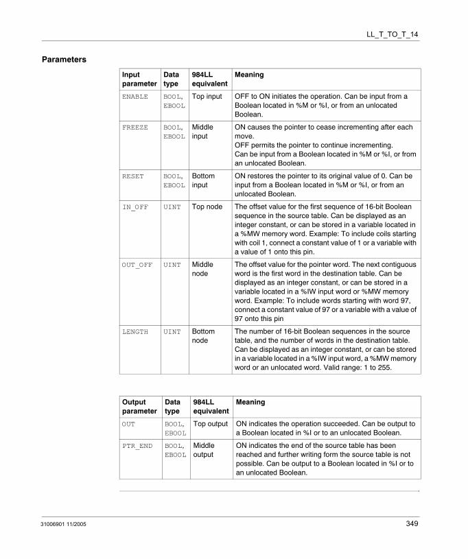
LL_T_TO_T_14
Parameters
Input parameter
Data type
984LL equivalent
Meaning
ENABLE BOOL, EBOOL
Top input OFF to ON initiates the operation. Can be input from a Boolean located in %M or %I, or from an unlocated Boolean.
FREEZE BOOL, EBOOL
Middle input
ON causes the pointer to cease incrementing after each move. OFF permits the pointer to continue incrementing. Can be input from a Boolean located in %M or %I, or from an unlocated Boolean.
RESET BOOL, EBOOL
Bottom input
ON restores the pointer to its original value of 0. Can be input from a Boolean located in %M or %I, or from an unlocated Boolean.
IN_OFF UINT Top node The offset value for the first sequence of 16-bit Boolean sequence in the source table. Can be displayed as an integer constant, or can be stored in a variable located in a %MW memory word. Example: To include coils starting with coil 1, connect a constant value of 1 or a variable with a value of 1 onto this pin.
OUT_OFF UINT Middle node
The offset value for the pointer word. The next contiguous word is the first word in the destination table. Can be displayed as an integer constant, or can be stored in a variable located in a %IW input word or %MW memory word. Example: To include words starting with word 97, connect a constant value of 97 or a variable with a value of 97 onto this pin
LENGTH UINT Bottom node
The number of 16-bit Boolean sequences in the source table, and the number of words in the destination table. Can be displayed as an integer constant, or can be stored in a variable located in a %IW input word, a %MW memory word or an unlocated word. Valid range: 1 to 255.
Output parameter
Data type
984LL equivalent
Meaning
OUT BOOL, EBOOL
Top output ON indicates the operation succeeded. Can be output to a Boolean located in %I or to an unlocated Boolean.
PTR_END BOOL, EBOOL
Middle output
ON indicates the end of the source table has been reached and further writing form the source table is not possible. Can be output to a Boolean located in %I or to an unlocated Boolean.
31006901 11/2005 349

LL_T_TO_T_14
350 31006901 11/2005
31006901 11/2005
85
LL_T_TO_T_34: Table to Table (%IW - %MW)Description
Function Description
The LL_T_TO_T_34 instruction copies the bit pattern of an input word positioned in a %IW source table to a word occupying the same relative position in a destination table located in %MW memory. It can write the contents of 1 word per scan until the contents of every word in the source table has been written to a word occupying the same relative position in the destination table.
The LENGTH value indicates both the number of words in the source table and the number of words in the destination table. The IN_OFF offset value defines the location of the first word in the source table.
The OUT_OFF offset value defines the location of the destination table’s pointer. This word points into both the source and destination tables, indicating where the data will be copied from and to in the current scan. The word contiguous to and following the pointer is the first word in the destination table.
The operation begins when the input to the ENABLE pin is turned ON. If both the FREEZE and RESET inputs remain OFF during operation, the pointer will increment by a value of 1 after each scan, causing the operation to copy data from the next adjacent word in the source table and write to the next adjacent word within the destination table.
The operation continues to copy data from the source table to the destination table until the operation reaches the end of the both tables, or until either of the following events occurs. If the FREEZE input turns ON, the pointer stops incrementing and the operation continues to write from the same word in the source table to the same word in the destination table. If the RESET input turns ON, the pointer is reset to 0 and the operation moves to and writes from the first word in the source table to the first word in the destination table.
The OUT output turns ON upon the successful completion of the operation. The PTR_END output turns ON if the pointer value equals the LENGTH value, indicating the end of both tables has been reached and no additional source data can be written to the destination table.
EN and ENO can be configured as additional parameters.
351

LL_T_TO_T_34
Representation in FBD
Representation in LD
Representation in IL
CAL LL_T_TO_T_34_Instance (ENABLE:=Trigger, FREEZE:=StopIncrement, RESET:=ZeroIncrement, IN_OFF:=Source, OUT_OFF:=Destination, LENGTH:=Integer1, OUT=>Success, PTR_END=>Filled)
Representation in ST
LL_T_TO_T_34_Instance (ENABLE:=Trigger, FREEZE:=StopIncrement, RESET:=ZeroIncrement, IN_OFF:=Source, OUT_OFF:=Destination, LENGTH:=Integer1, OUT=>Success, PTR_END=>Filled);
LL_T_TO_T_34
TriggerStopIncrement
LL_T_TO_T_34_Instance
OUTENABLEFREEZERESETIN_OFF
ZeroIncrementSource
SuccessPTR_END Filled
OUT_OFFDestinationLENGTHInteger1
Trigger
Source
ENOENSuccess
LL_T_TO_T_34LL_T_TO_T_34_Instance
OUTENABLE
IN_OFF
OUT_OFF
LENGTH
Destination
Integer1
FilledPTR_END
ZeroIncrementRESET
StopIncrementFREEZE
352 31006901 11/2005
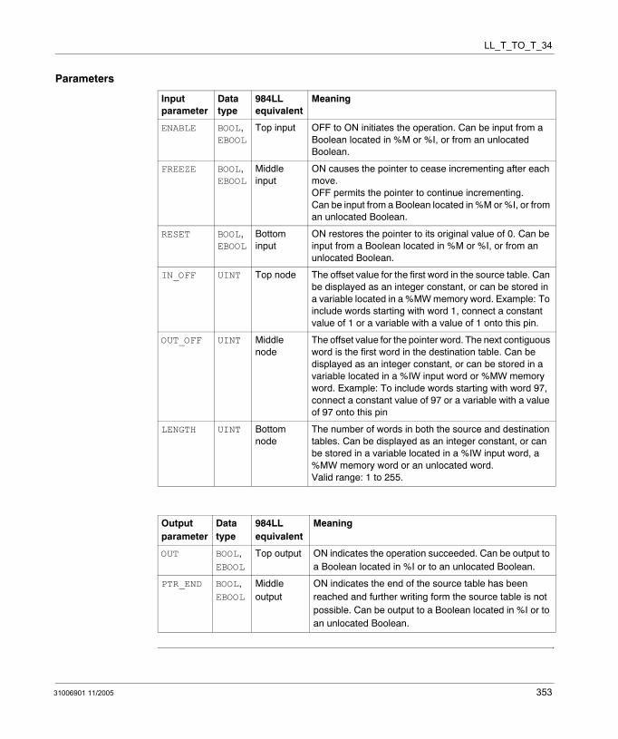
LL_T_TO_T_34
Parameters
Input parameter
Data type
984LL equivalent
Meaning
ENABLE BOOL, EBOOL
Top input OFF to ON initiates the operation. Can be input from a Boolean located in %M or %I, or from an unlocated Boolean.
FREEZE BOOL, EBOOL
Middle input
ON causes the pointer to cease incrementing after each move. OFF permits the pointer to continue incrementing. Can be input from a Boolean located in %M or %I, or from an unlocated Boolean.
RESET BOOL, EBOOL
Bottom input
ON restores the pointer to its original value of 0. Can be input from a Boolean located in %M or %I, or from an unlocated Boolean.
IN_OFF UINT Top node The offset value for the first word in the source table. Can be displayed as an integer constant, or can be stored in a variable located in a %MW memory word. Example: To include words starting with word 1, connect a constant value of 1 or a variable with a value of 1 onto this pin.
OUT_OFF UINT Middle node
The offset value for the pointer word. The next contiguous word is the first word in the destination table. Can be displayed as an integer constant, or can be stored in a variable located in a %IW input word or %MW memory word. Example: To include words starting with word 97, connect a constant value of 97 or a variable with a value of 97 onto this pin
LENGTH UINT Bottom node
The number of words in both the source and destination tables. Can be displayed as an integer constant, or can be stored in a variable located in a %IW input word, a %MW memory word or an unlocated word. Valid range: 1 to 255.
Output parameter
Data type
984LL equivalent
Meaning
OUT BOOL, EBOOL
Top output ON indicates the operation succeeded. Can be output to a Boolean located in %I or to an unlocated Boolean.
PTR_END BOOL, EBOOL
Middle output
ON indicates the end of the source table has been reached and further writing form the source table is not possible. Can be output to a Boolean located in %I or to an unlocated Boolean.
31006901 11/2005 353

LL_T_TO_T_34
354 31006901 11/2005
31006901 11/2005
86
LL_T_TO_T_44: Table to Table (%MW - %MW)Description
Function Description
The LL_T_TO_T_44 instruction copies the bit pattern of a word positioned in a source table located in %MW memory to another word occupying the same relative position in a destination table also located in %MW memory. It can write the contents of 1 word per scan until the contents of every word in the source table has been written to a word occupying the same relative position in the destination table.
The LENGTH value indicates both the number of words in the source table and the number of words in the destination table. The IN_OFF offset value defines the location of the first word in the source table.
The OUT_OFF offset value defines the location of the destination table’s pointer. This word points into both the source and destination tables, indicating where the data will be copied from and to in the current scan. The word contiguous to and following the pointer is the first word in the destination table.
The operation begins when the input to the ENABLE pin is turned ON. If both the FREEZE and RESET inputs remain OFF during operation, the pointer will increment by a value of 1 after each scan, causing the operation to copy data from the next adjacent word in the source table and write to the next adjacent word within the destination table.
The operation continues to copy data from the source table to the destination table until the operation reaches the end of the both tables, or until either of the following events occurs. If the FREEZE input turns ON, the pointer stops incrementing and the operation continues to write from the same word in the source table to the same word in the destination table. If the RESET input turns ON, the pointer is reset to 0 and the operation moves to and writes from the first word in the source table to the first word in the destination table.
The OUT output turns ON upon the successful completion of the operation. The PTR_END output turns ON if the pointer value equals the LENGTH value, indicating the end of both tables has been reached and no additional source data can be written to the destination table.
EN and ENO can be configured as additional parameters.
355

LL_T_TO_T_44
Representation in FBD
Representation in LD
Representation in IL
CAL LL_T_TO_T_44_Instance (ENABLE:=Trigger, FREEZE:=StopIncrement, RESET:=ZeroIncrement, IN_OFF:=Source, OUT_OFF:=Destination, LENGTH:=Integer1, OUT=>Success, PTR_END=>Filled)
Representation in ST
LL_T_TO_T_44_Instance (ENABLE:=Trigger, FREEZE:=StopIncrement, RESET:=ZeroIncrement, IN_OFF:=Source, OUT_OFF:=Destination, LENGTH:=Integer1, OUT=>Success, PTR_END=>Filled);
LL_T_TO_T_44
TriggerStopIncrement
LL_T_TO_T_44_Instance
OUTENABLEFREEZERESETIN_OFF
ZeroIncrementSource
SuccessPTR_END Filled
OUT_OFFDestinationLENGTHInteger1
Trigger
Source
ENOENSuccess
LL_T_TO_T_44LL_T_TO_T_44_Instance
OUTENABLE
IN_OFF
OUT_OFF
LENGTH
Destination
Integer1
FilledPTR_END
ZeroIncrementRESET
StopIncrementFREEZE
356 31006901 11/2005
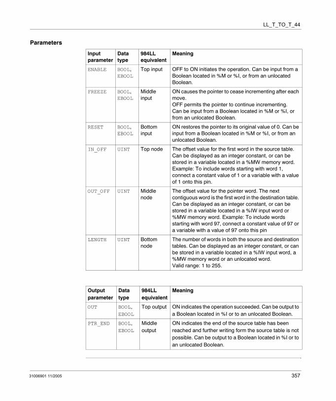
LL_T_TO_T_44
Parameters
Input parameter
Data type
984LL equivalent
Meaning
ENABLE BOOL, EBOOL
Top input OFF to ON initiates the operation. Can be input from a Boolean located in %M or %I, or from an unlocated Boolean.
FREEZE BOOL, EBOOL
Middle input
ON causes the pointer to cease incrementing after each move. OFF permits the pointer to continue incrementing. Can be input from a Boolean located in %M or %I, or from an unlocated Boolean.
RESET BOOL, EBOOL
Bottom input
ON restores the pointer to its original value of 0. Can be input from a Boolean located in %M or %I, or from an unlocated Boolean.
IN_OFF UINT Top node The offset value for the first word in the source table. Can be displayed as an integer constant, or can be stored in a variable located in a %MW memory word. Example: To include words starting with word 1, connect a constant value of 1 or a variable with a value of 1 onto this pin.
OUT_OFF UINT Middle node
The offset value for the pointer word. The next contiguous word is the first word in the destination table. Can be displayed as an integer constant, or can be stored in a variable located in a %IW input word or %MW memory word. Example: To include words starting with word 97, connect a constant value of 97 or a variable with a value of 97 onto this pin
LENGTH UINT Bottom node
The number of words in both the source and destination tables. Can be displayed as an integer constant, or can be stored in a variable located in a %IW input word, a %MW memory word or an unlocated word. Valid range: 1 to 255.
Output parameter
Data type
984LL equivalent
Meaning
OUT BOOL, EBOOL
Top output ON indicates the operation succeeded. Can be output to a Boolean located in %I or to an unlocated Boolean.
PTR_END BOOL, EBOOL
Middle output
ON indicates the end of the source table has been reached and further writing form the source table is not possible. Can be output to a Boolean located in %I or to an unlocated Boolean.
31006901 11/2005 357

LL_T_TO_T_44
358 31006901 11/2005
31006901 11/2005
87
LL_TBLK: Table to BlockDescription
Function Description
The LL_TBLK table-to-block instruction combines the functionality of a table-to-register instruction with a block move instruction. In a single scan, it can copy a block of up to 100 contiguous words from a source table to a destination block of words. The length of the destination block of words is fixed. Each block of words copied from the source table must be the same length; however, the overall size of the source table is limited only by the number of words in your system configuration.
Both the source table and the destination words are located in %MW memory. The LENGTH value determines the number of words included in the destination block. The IN_OFF offset value defines the location of the first word in the source table.
The OUT_OFF offset value defines the location of the pointer. The pointer contains an integer value which, when multiplied against the LENGTH value, points to the first word of the block in the source table that will be copied and written to the destination block in the current scan. The initial value of the pointer is 0, which points to the first word in the source table. The word contiguous to and immediately following the pointer is the first word in the destination block.
Note: The source table is segmented into a series of blocks, each of which is the same length as the destination block. Consequently, the size of the source table is a multiple of the length of the destination block, although its overall size is not defined in the instruction. If left uncontrolled, the source table could consume all the located words available in the PLC configuration.
359
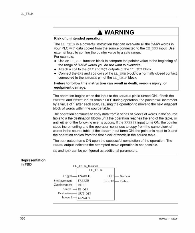
LL_TBLK
The operation begins when the input to the ENABLE pin is turned ON. If both the FREEZE and RESET inputs remain OFF during operation, the pointer will increment by a value of 1 after each scan, causing the operation to move to the next adjacent block of words within the source table.
The operation continues to copy data from a series of blocks of words in the source table to a the destination blocks until the operation reaches the end of the table, or until either of the following events occurs. If the FREEZE input turns ON, the pointer stops incrementing and the operation continues to copy from the same block of words in the source table. If the RESET input turns ON, the pointer is reset to 0, and the operation copies from the first block of words in the source table.
The OUT output turns ON upon the successful completion of the operation. The ERROR output indicates the attempted move operation is not possible.
EN and ENO can be configured as additional parameters.
Representation in FBD
Risk of unintended operation.The LL_TBLK is a powerful instruction that can overwrite all the %MW words in your PLC with data copied from the source connected to the IN_OFF input. Use external logic to confine the pointer value to a safe range.For example:
Use an LL_SUB function block to compare the pointer value to the beginning of the range of %MW words you do not want to overwrite.Attach a coil to the GRT and EQT outputs of the LL_SUB block.Connect the GRT and EQT coils of the LL_SUB block to a normally closed contact connected to the ENABLE pin of the LL_TBLK block.
Failure to follow this instruction can result in death, serious injury, or equipment damage.
WARNING
LL_TBLK
TriggerStopIncrement
LL_TBLK_Instance
OUTENABLEFREEZERESETIN_OFF
ZeroIncrementSource
SuccessERROR Failure
OUT_OFFDestinationLENGTHInteger1
360 31006901 11/2005
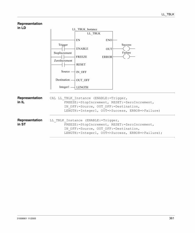
LL_TBLK
Representation in LD
Representation in IL
CAL LL_TBLK_Instance (ENABLE:=Trigger, FREEZE:=StopIncrement, RESET:=ZeroIncrement, IN_OFF:=Source, OUT_OFF:=Destination, LENGTH:=Integer1, OUT=>Success, ERROR=>Failure)
Representation in ST
LL_TBLK_Instance (ENABLE:=Trigger, FREEZE:=StopIncrement, RESET:=ZeroIncrement, IN_OFF:=Source, OUT_OFF:=Destination, LENGTH:=Integer1, OUT=>Success, ERROR=>Failure);
Trigger
Source
ENOENSuccess
LL_TBLKLL_TBLK_Instance
OUTENABLE
IN_OFF
OUT_OFF
LENGTH
Destination
Integer1
FailureERROR
ZeroIncrementRESET
StopIncrementFREEZE
31006901 11/2005 361
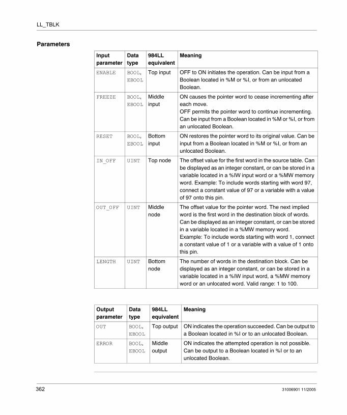
LL_TBLK
Parameters
Input parameter
Data type
984LL equivalent
Meaning
ENABLE BOOL, EBOOL
Top input OFF to ON initiates the operation. Can be input from a Boolean located in %M or %I, or from an unlocated Boolean.
FREEZE BOOL, EBOOL
Middle input
ON causes the pointer word to cease incrementing after each move. OFF permits the pointer word to continue incrementing. Can be input from a Boolean located in %M or %I, or from an unlocated Boolean.
RESET BOOL, EBOOL
Bottom input
ON restores the pointer word to its original value. Can be input from a Boolean located in %M or %I, or from an unlocated Boolean.
IN_OFF UINT Top node The offset value for the first word in the source table. Can be displayed as an integer constant, or can be stored in a variable located in a %IW input word or a %MW memory word. Example: To include words starting with word 97, connect a constant value of 97 or a variable with a value of 97 onto this pin.
OUT_OFF UINT Middle node
The offset value for the pointer word. The next implied word is the first word in the destination block of words. Can be displayed as an integer constant, or can be stored in a variable located in a %MW memory word. Example: To include words starting with word 1, connect a constant value of 1 or a variable with a value of 1 onto this pin.
LENGTH UINT Bottom node
The number of words in the destination block. Can be displayed as an integer constant, or can be stored in a variable located in a %IW input word, a %MW memory word or an unlocated word. Valid range: 1 to 100.
Output parameter
Data type
984LL equivalent
Meaning
OUT BOOL, EBOOL
Top output ON indicates the operation succeeded. Can be output to a Boolean located in %I or to an unlocated Boolean.
ERROR BOOL, EBOOL
Middle output
ON indicates the attempted operation is not possible. Can be output to a Boolean located in %I or to an unlocated Boolean.
362 31006901 11/2005
Appendices
Introduction
What's in this Appendix?
The appendix contains the following chapters:
Chapter Chapter Name Page
A EFB Error Codes and Values 365
B System objects 367
31006901 11/2005 363

Appendices
364 31006901 11/2005
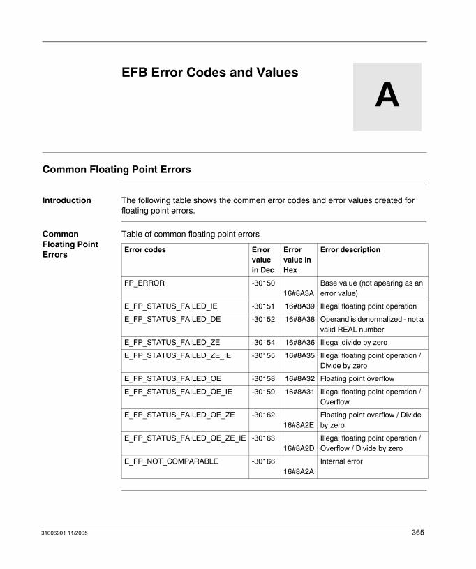
31006901 11/2005
A
EFB Error Codes and ValuesCommon Floating Point Errors
Introduction The following table shows the commen error codes and error values created for floating point errors.
Common Floating Point Errors
Table of common floating point errors
Error codes Error value in Dec
Error value in Hex
Error description
FP_ERROR -30150 16#8A3A
Base value (not apearing as an error value)
E_FP_STATUS_FAILED_IE -30151 16#8A39 Illegal floating point operation
E_FP_STATUS_FAILED_DE -30152 16#8A38 Operand is denormalized - not a valid REAL number
E_FP_STATUS_FAILED_ZE -30154 16#8A36 Illegal divide by zero
E_FP_STATUS_FAILED_ZE_IE -30155 16#8A35 Illegal floating point operation / Divide by zero
E_FP_STATUS_FAILED_OE -30158 16#8A32 Floating point overflow
E_FP_STATUS_FAILED_OE_IE -30159 16#8A31 Illegal floating point operation / Overflow
E_FP_STATUS_FAILED_OE_ZE -30162 16#8A2E
Floating point overflow / Divide by zero
E_FP_STATUS_FAILED_OE_ZE_IE -30163 16#8A2D
Illegal floating point operation / Overflow / Divide by zero
E_FP_NOT_COMPARABLE -30166 16#8A2A
Internal error
365

EFB Error Codes and Values
366 31006901 11/2005
31006901 11/2005
B
System objectsAt a Glance
Overview This chapter describes the system bits and words of Unity Pro language.
Note: The symbols, associated with each bit object or system word, mentioned in the descriptive tables of these objects, are not implemented as standard in the software, but can be entered using the data editor.
They are proposed in order to ensure the homogeneity of their names in the different applications.
What's in this Chapter?
This chapter contains the following topics:
Topic Page
System bit introduction 368
Description of System Bits %S9 to %S13 369
Description of system bits %S15 to %S21 370
Description of System Words %SW12 to %SW19 372
367
System objects
System bit introduction
General The Premium, Atrium and Quantum PLCs use %Si system bits which indicate the state of the PLC, or they can be used to control how it operates.
These bits can be tested in the user program to detect any functional development requiring a set processing procedure.
Some of these bits must be reset to their initial or normal state by the program. However, the system bits that are reset to their initial or normal state by the system must not be reset by the program or by the terminal.
368 31006901 11/2005
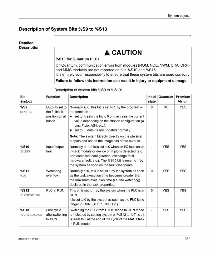
System objects
Description of System Bits %S9 to %S13
Detailed Description
Description of system bits %S9 to %S13:
%S10 for Quantum PLCsOn Quantum, communication errors from modules (NOM, NOE, NWM, CRA, CRP) and MMS modules are not reported on bits %S10 and %S16.It is entirely your responsibility to ensure that these system bits are used correctly
Failure to follow this instruction can result in injury or equipment damage.
CAUTION
BitSymbol
Function Description Initial state
Quantum Premium Atrium
%S9OUTDIS
Outputs set to the fallback position on all buses
Normally at 0, this bit is set to 1 by the program or the terminal:
set to 1: sets the bit to 0 or maintains the current value depending on the chosen configuration (X bus, Fipio, AS-i, etc.),set to 0: outputs are updated normally.
Note: The system bit acts directly on the physical outputs and not on the image bits of the outputs.
0 NO YES
%S10IOERR
Input/output fault
Normally at 1, this is set to 0 when an I/O fault on an in-rack module or device on Fipio is detected (e.g. non-compliant configuration, exchange fault, hardware fault, etc.). The %S10 bit is reset to 1 by the system as soon as the fault disappears.
1 YES YES
%S11WDG
Watchdog overflow
Normally at 0, this is set to 1 by the system as soon as the task execution time becomes greater than the maximum execution time (i.e. the watchdog) declared in the task properties.
0 YES YES
%S12PLCRUNNING
PLC in RUN This bit is set to 1 by the system when the PLC is in RUN.It is set to 0 by the system as soon as the PLC is no longer in RUN (STOP, INIT, etc.).
0 YES YES
%S131RSTSCANRUN
First cycle after switching to RUN
Switching the PLC from STOP mode to RUN mode is indicated by setting system bit %S13 to 1. This bit is reset to 0 at the end of the cycle of the MAST task in RUN mode.
- YES YES
31006901 11/2005 369
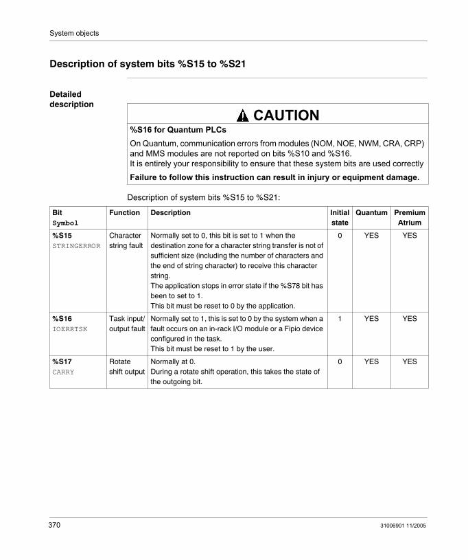
System objects
Description of system bits %S15 to %S21
Detailed description
Description of system bits %S15 to %S21:
%S16 for Quantum PLCsOn Quantum, communication errors from modules (NOM, NOE, NWM, CRA, CRP) and MMS modules are not reported on bits %S10 and %S16.It is entirely your responsibility to ensure that these system bits are used correctly
Failure to follow this instruction can result in injury or equipment damage.
CAUTION
BitSymbol
Function Description Initial state
Quantum Premium Atrium
%S15STRINGERROR
Character string fault
Normally set to 0, this bit is set to 1 when the destination zone for a character string transfer is not of sufficient size (including the number of characters and the end of string character) to receive this character string.The application stops in error state if the %S78 bit has been to set to 1.This bit must be reset to 0 by the application.
0 YES YES
%S16IOERRTSK
Task input/output fault
Normally set to 1, this is set to 0 by the system when a fault occurs on an in-rack I/O module or a Fipio device configured in the task.This bit must be reset to 1 by the user.
1 YES YES
%S17CARRY
Rotate shift output
Normally at 0.During a rotate shift operation, this takes the state of the outgoing bit.
0 YES YES
370 31006901 11/2005
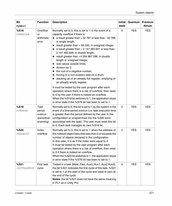
System objects
%S18OVERFLOW
Overflow or arithmetic error
Normally set to 0, this is set to 1 in the event of a capacity overflow if there is:
a result greater than + 32 767 or less than - 32 768, in single length,result greater than + 65 535, in unsigned integer,a result greater than + 2 147 483 647 or less than - 2 147 483 648, in double length,result greater than +4 294 967 296, in double length or unsigned integer,real values outside limits,division by 0,the root of a negative number,forcing to a non-existent step on a drum.stacking up of an already full register, emptying of an already empty register.
It must be tested by the user program after each operation where there is a risk of overflow, then reset to 0 by the user if there is indeed an overflow.When the %S18 bit switches to 1, the application stops in error state if the %S78 bit has been to set to 1.
0 YES YES
%S19OVERRUN
Task period overrun (periodical scanning)
Normally set to 0, this bit is set to 1 by the system in the event of a time period overrun (i.e. task execution time is greater than the period defined by the user in the configuration or programmed into the %SW word associated with the task). The user must reset this bit to 0. Each task manages its own %S19 bit.
0 YES YES
%S20INDEXOVF
Index overflow
Normally set to 0, this is set to 1 when the address of the indexed object becomes less than 0 or exceeds the number of objects declared in the configuration.In this case, it is as if the index were equal to 0.It must be tested by the user program after each operation where there is a risk of overflow, then reset to 0 if there is indeed an overflow. When the %S20 bit switches to 1, the application stops in error state if the %S78 bit has been to set to 1.
0 YES YES
%S211RSTTASKRUN
First task cycle
Tested in a task (Mast, Fast, Aux0, Aux1, Aux2 Aux3), the bit %S21 indicates the first cycle of this task. %S21 is set to 1 at the start of the cycle and reset to zero at the end of the cycle.Notes: the bit %S21 does not have the same meaning in PL7 as in Unity Pro.
0 YES YES
BitSymbol
Function Description Initial state
Quantum Premium Atrium
31006901 11/2005 371
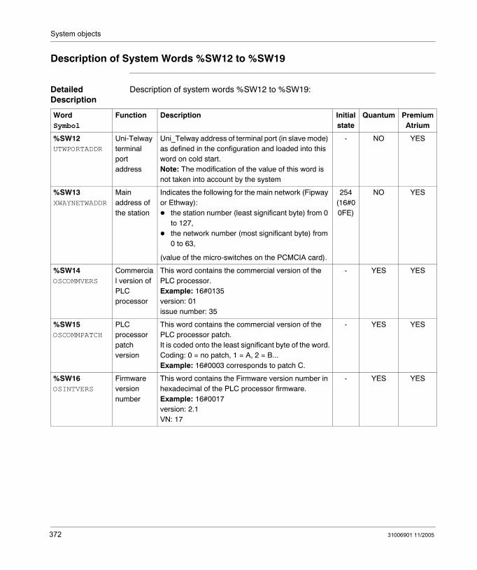
System objects
Description of System Words %SW12 to %SW19
Detailed Description
Description of system words %SW12 to %SW19:
WordSymbol
Function Description Initial state
Quantum Premium Atrium
%SW12UTWPORTADDR
Uni-Telway terminal port address
Uni_Telway address of terminal port (in slave mode) as defined in the configuration and loaded into this word on cold start.Note: The modification of the value of this word is not taken into account by the system
- NO YES
%SW13XWAYNETWADDR
Main address of the station
Indicates the following for the main network (Fipway or Ethway):
the station number (least significant byte) from 0 to 127,the network number (most significant byte) from 0 to 63,
(value of the micro-switches on the PCMCIA card).
254(16#00FE)
NO YES
%SW14OSCOMMVERS
Commercial version of PLC processor
This word contains the commercial version of the PLC processor.Example: 16#0135version: 01issue number: 35
- YES YES
%SW15OSCOMMPATCH
PLC processor patch version
This word contains the commercial version of the PLC processor patch.It is coded onto the least significant byte of the word.Coding: 0 = no patch, 1 = A, 2 = B...Example: 16#0003 corresponds to patch C.
- YES YES
%SW16OSINTVERS
Firmware version number
This word contains the Firmware version number in hexadecimal of the PLC processor firmware.Example: 16#0017version: 2.1VN: 17
- YES YES
372 31006901 11/2005
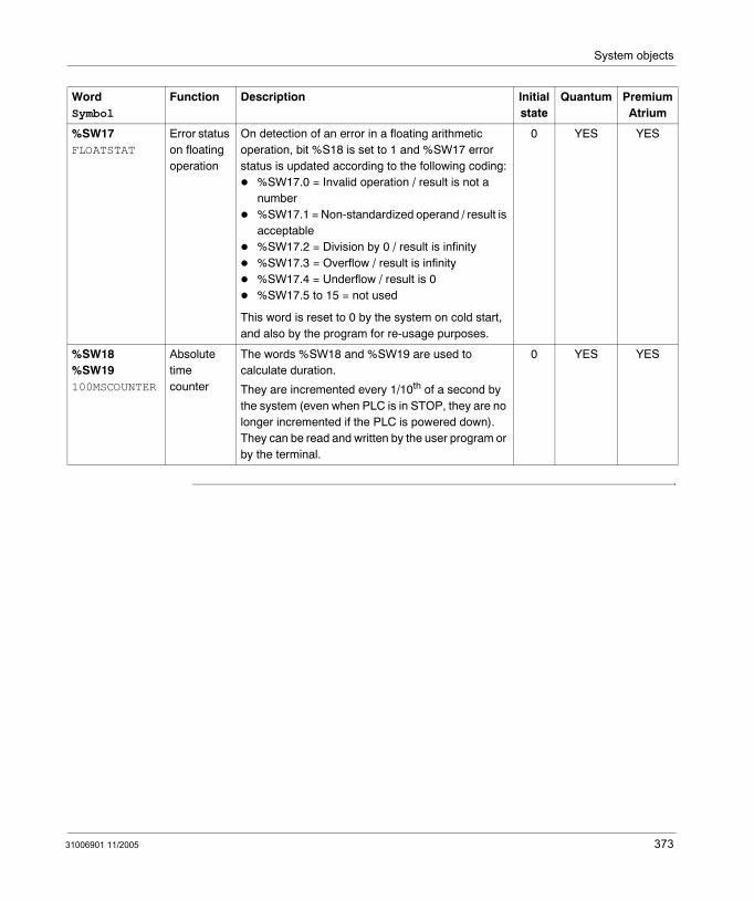
System objects
%SW17FLOATSTAT
Error status on floating operation
On detection of an error in a floating arithmetic operation, bit %S18 is set to 1 and %SW17 error status is updated according to the following coding:
%SW17.0 = Invalid operation / result is not a number%SW17.1 = Non-standardized operand / result is acceptable%SW17.2 = Division by 0 / result is infinity%SW17.3 = Overflow / result is infinity%SW17.4 = Underflow / result is 0%SW17.5 to 15 = not used
This word is reset to 0 by the system on cold start, and also by the program for re-usage purposes.
0 YES YES
%SW18%SW19100MSCOUNTER
Absolute time counter
The words %SW18 and %SW19 are used to calculate duration.
They are incremented every 1/10th of a second by the system (even when PLC is in STOP, they are no longer incremented if the PLC is powered down). They can be read and written by the user program or by the terminal.
0 YES YES
WordSymbol
Function Description Initial state
Quantum Premium Atrium
31006901 11/2005 373

System objects
374 31006901 11/2005
Glossary
%I According to the IEC standard, %I indicates a discrete input-type language object.
%IW According to the IEC standard, %IW indicates an analog input -type language object.
%KW According to the IEC standard, %KW indicates a constant word-type language object.
%M According to the IEC standard, %M indicates a memory bit-type language object.
%MW According to the IEC standard, %MW indicates a memory word-type language object.
%Q According to the IEC standard, %Q indicates a discrete output-type language object.
%QW According to the IEC standard, %QW indicates an analog output-type language object.
ADDR_TYPE This predefined type is used as output for ADDR function. This type is ARRAY[0..5] OF Int. You can find it in the libset, in the same family than the EFs which use it.
ANL_IN ANL_IN is the abbreviation of Analog Input data type and is used when processing analog values. The %IW adresses for the configured analog input module, which were specified in the I/O component list, are automatically assigned data types and should therefore only be occupied with Unlocated Variables.
!
A
31006901 11/2005 375
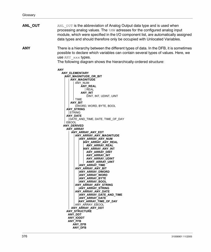
Glossary
ANL_OUT ANL_OUT is the abbreviation of Analog Output data type and is used when processing analog values. The %MW adresses for the configured analog input module, which were specified in the I/O component list, are automatically assigned data types and should therefore only be occupied with Unlocated Variables.
ANY There is a hierarchy between the different types of data. In the DFB, it is sometimes possible to declare which variables can contain several types of values. Here, we use ANY_xxx types. The following diagram shows the hierarchically-ordered structure:
ANY ANY_ELEMENTARY ANY_MAGNITUDE_OR_BIT ANY_MAGNITUDE ANY_NUM ANY_REAL REAL ANY_INT DINT, INT, UDINT, UINT TIME ANY_BIT DWORD, WORD, BYTE, BOOL ANY_STRING STRING ANY_DATE DATE_AND_TIME, DATE, TIME_OF_DAY EBOOL ANY_DERIVED ANY_ARRAY ANY_ARRAY_ANY_EDT ANY_ARRAY_ANY_MAGNITUDE ANY_ARRAY_ANY_NUM ANY_ARRAY_ANY_REAL ANY_ARRAY_REAL ANY_ARRAY_ANY_INT ANY_ARRAY_DINT ANY_ARRAY_INT ANY_ARRAY_UDINT ANNY_ARRAY_UINT ANY_ARRAY_TIME ANY_ARRAY_ANY_BIT ANY_ARRAY_DWORD ANY_ARRAY_WORD ANY_ARRAY_BYTE ANY_ARRAY_BOOL ANY_ARRAY_ANY_STRING ANY_ARRAY_STRING ANY_ARRAY_ANY_DATE ANY_ARRAY_DATE_AND_TIME ANY_ARRAY_DATE ANY_ARRAY_TIME_OF_DAY ANY_ARRAY_EBOOL ANY_ARRAY_ANY_DDT ANY_STRUCTURE ANY_DDT ANY_IODDT ANY_FFB ANY_EFB ANY_DFB
376 31006901 11/2005
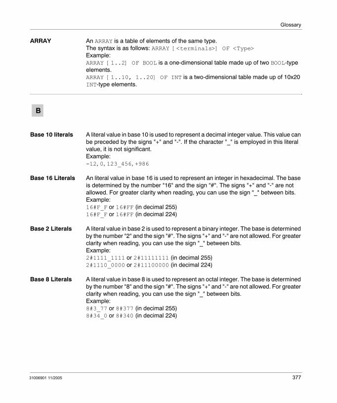
Glossary
ARRAY An ARRAY is a table of elements of the same type.The syntax is as follows: ARRAY [<terminals>] OF <Type>Example:ARRAY [1..2] OF BOOL is a one-dimensional table made up of two BOOL-type elements.ARRAY [1..10, 1..20] OF INT is a two-dimensional table made up of 10x20 INT-type elements.
Base 10 literals A literal value in base 10 is used to represent a decimal integer value. This value can be preceded by the signs "+" and "-". If the character "_" is employed in this literal value, it is not significant.Example:-12, 0, 123_456, +986
Base 16 Literals An literal value in base 16 is used to represent an integer in hexadecimal. The base is determined by the number "16" and the sign "#". The signs "+" and "-" are not allowed. For greater clarity when reading, you can use the sign "_" between bits.Example:16#F_F or 16#FF (in decimal 255)16#F_F or 16#FF (in decimal 224)
Base 2 Literals A literal value in base 2 is used to represent a binary integer. The base is determined by the number "2" and the sign "#". The signs "+" and "-" are not allowed. For greater clarity when reading, you can use the sign "_" between bits.Example:2#1111_1111 or 2#11111111 (in decimal 255)2#1110_0000 or 2#11100000 (in decimal 224)
Base 8 Literals A literal value in base 8 is used to represent an octal integer. The base is determined by the number "8" and the sign "#". The signs "+" and "-" are not allowed. For greater clarity when reading, you can use the sign "_" between bits.Example:8#3_77 or 8#377 (in decimal 255)8#34_0 or 8#340 (in decimal 224)
B
31006901 11/2005 377
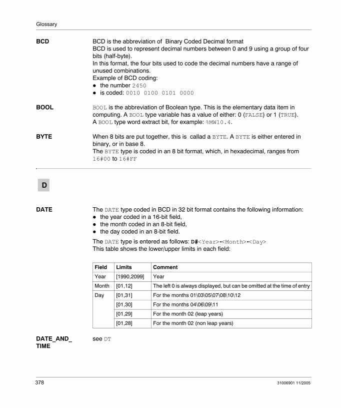
Glossary
BCD BCD is the abbreviation of Binary Coded Decimal format BCD is used to represent decimal numbers between 0 and 9 using a group of four bits (half-byte).In this format, the four bits used to code the decimal numbers have a range of unused combinations.Example of BCD coding:
the number 2450 is coded: 0010 0100 0101 0000
BOOL BOOL is the abbreviation of Boolean type. This is the elementary data item in computing. A BOOL type variable has a value of either: 0 (FALSE) or 1 (TRUE).A BOOL type word extract bit, for example: %MW10.4.
BYTE When 8 bits are put together, this is callad a BYTE. A BYTE is either entered in binary, or in base 8.The BYTE type is coded in an 8 bit format, which, in hexadecimal, ranges from 16#00 to 16#FF
DATE The DATE type coded in BCD in 32 bit format contains the following information: the year coded in a 16-bit field,the month coded in an 8-bit field,the day coded in an 8-bit field.
The DATE type is entered as follows: D#<Year>-<Month>-<Day> This table shows the lower/upper limits in each field:
DATE_AND_TIME
see DT
D
Field Limits Comment
Year [1990,2099] Year
Month [01,12] The left 0 is always displayed, but can be omitted at the time of entry
Day [01,31] For the months 01\03\05\07\08\10\12
[01,30] For the months 04\06\09\11
[01,29] For the month 02 (leap years)
[01,28] For the month 02 (non leap years)
378 31006901 11/2005
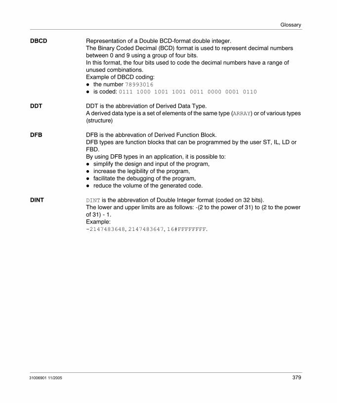
Glossary
DBCD Representation of a Double BCD-format double integer.The Binary Coded Decimal (BCD) format is used to represent decimal numbers between 0 and 9 using a group of four bits.In this format, the four bits used to code the decimal numbers have a range of unused combinations.Example of DBCD coding:
the number 78993016is coded: 0111 1000 1001 1001 0011 0000 0001 0110
DDT DDT is the abbreviation of Derived Data Type.A derived data type is a set of elements of the same type (ARRAY) or of various types (structure)
DFB DFB is the abbrevation of Derived Function Block.DFB types are function blocks that can be programmed by the user ST, IL, LD or FBD.By using DFB types in an application, it is possible to:
simplify the design and input of the program,increase the legibility of the program,facilitate the debugging of the program,reduce the volume of the generated code.
DINT DINT is the abbrevation of Double Integer format (coded on 32 bits). The lower and upper limits are as follows: -(2 to the power of 31) to (2 to the power of 31) - 1.Example:-2147483648, 2147483647, 16#FFFFFFFF.
31006901 11/2005 379
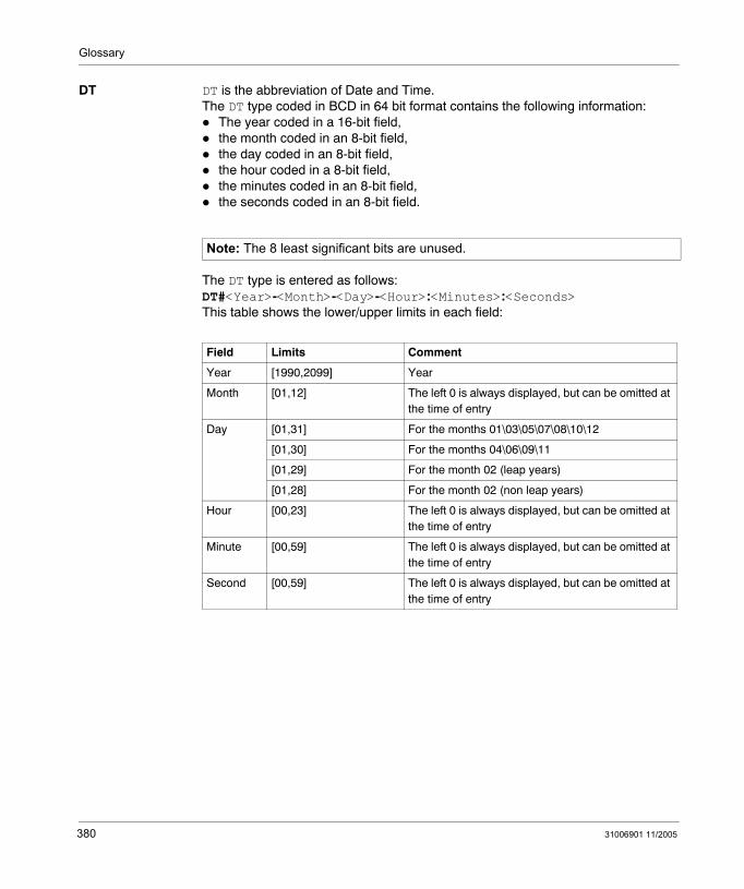
Glossary
DT DT is the abbreviation of Date and Time.The DT type coded in BCD in 64 bit format contains the following information:
The year coded in a 16-bit field,the month coded in an 8-bit field,the day coded in an 8-bit field,the hour coded in a 8-bit field,the minutes coded in an 8-bit field,the seconds coded in an 8-bit field.
The DT type is entered as follows:DT#<Year>-<Month>-<Day>-<Hour>:<Minutes>:<Seconds>This table shows the lower/upper limits in each field:
Note: The 8 least significant bits are unused.
Field Limits Comment
Year [1990,2099] Year
Month [01,12] The left 0 is always displayed, but can be omitted at the time of entry
Day [01,31] For the months 01\03\05\07\08\10\12
[01,30] For the months 04\06\09\11
[01,29] For the month 02 (leap years)
[01,28] For the month 02 (non leap years)
Hour [00,23] The left 0 is always displayed, but can be omitted at the time of entry
Minute [00,59] The left 0 is always displayed, but can be omitted at the time of entry
Second [00,59] The left 0 is always displayed, but can be omitted at the time of entry
380 31006901 11/2005
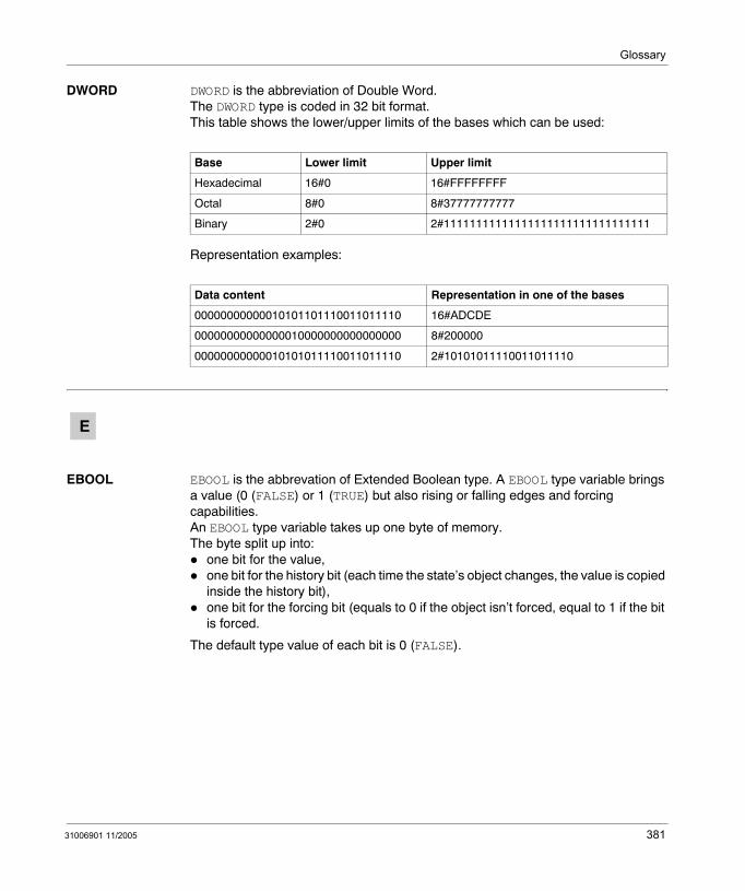
Glossary
DWORD DWORD is the abbreviation of Double Word.The DWORD type is coded in 32 bit format.This table shows the lower/upper limits of the bases which can be used:
Representation examples:
EBOOL EBOOL is the abbrevation of Extended Boolean type. A EBOOL type variable brings a value (0 (FALSE) or 1 (TRUE) but also rising or falling edges and forcing capabilities.An EBOOL type variable takes up one byte of memory.The byte split up into:
one bit for the value,one bit for the history bit (each time the state’s object changes, the value is copied inside the history bit),one bit for the forcing bit (equals to 0 if the object isn’t forced, equal to 1 if the bit is forced.
The default type value of each bit is 0 (FALSE).
Base Lower limit Upper limit
Hexadecimal 16#0 16#FFFFFFFF
Octal 8#0 8#37777777777
Binary 2#0 2#11111111111111111111111111111111
Data content Representation in one of the bases
00000000000010101101110011011110 16#ADCDE
00000000000000010000000000000000 8#200000
00000000000010101011110011011110 2#10101011110011011110
E
31006901 11/2005 381
Glossary
EF Is the abbreviation of Elementary Function.This is a block which is used in a program, and which performs a predefined software function.A function has no internal status information. Multiple invocations of the same function using the same input parameters always supply the same output values. Details of the graphic form of the function invocation can be found in the "[Functional block (instance)] ". In contrast to the invocation of the function blocks, function invocations only have a single unnamed output, whose name is the same as the function. In FBD each invocation is denoted by a unique [number] via the graphic block, this number is automatically generated and can not be altered.You position and set up these functions in your program in order to carry out your application. You can also develop other functions using the SDKC development kit.
EFB Is the abbreviation for Elementary Function Block.This is a block which is used in a program, and which performs a predefined software function.EFBs have internal statuses and parameters. Even where the inputs are identical, the output values may be different. For example, a counter has an output which indicates that the preselection value has been reached. This output is set to 1 when the current value is equal to the preselection value.
Elementary Function
see EF
EN EN means ENable, this is an optional block input. When EN is activated, an ENO output is automatically drafted. If EN = 0, the block is not activated, its internal program is not executed and ENO is set to 0.If EN = 1, the internal program of the block is executed, and ENO is set to 1 by the system. If an error occurs, ENO is set to 0.If EN is not connected, it is automatically set to 1.
ENO ENO means Error NOtification, this is the output associated to the optional input EN. If ENO is set to 0 (caused by EN=0 or in case of an execution error),
the outputs of function blocks remain in the status they were in for the last correct executed scanning cycle andthe output(s) of functions and procedures are set to "0".
382 31006901 11/2005
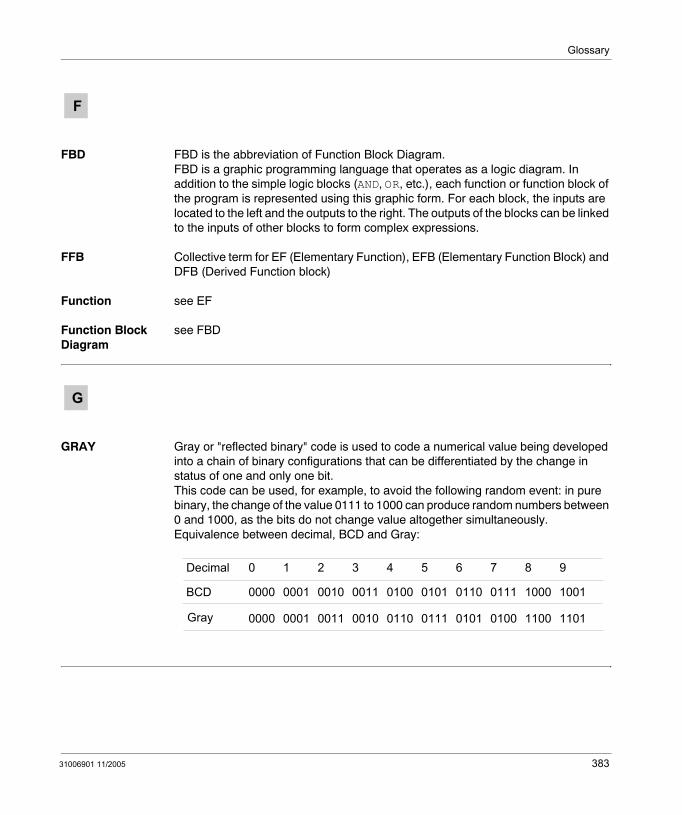
Glossary
FBD FBD is the abbreviation of Function Block Diagram. FBD is a graphic programming language that operates as a logic diagram. In addition to the simple logic blocks (AND, OR, etc.), each function or function block of the program is represented using this graphic form. For each block, the inputs are located to the left and the outputs to the right. The outputs of the blocks can be linked to the inputs of other blocks to form complex expressions.
FFB Collective term for EF (Elementary Function), EFB (Elementary Function Block) and DFB (Derived Function block)
Function see EF
Function Block Diagram
see FBD
GRAY Gray or "reflected binary" code is used to code a numerical value being developed into a chain of binary configurations that can be differentiated by the change in status of one and only one bit. This code can be used, for example, to avoid the following random event: in pure binary, the change of the value 0111 to 1000 can produce random numbers between 0 and 1000, as the bits do not change value altogether simultaneously.Equivalence between decimal, BCD and Gray:
F
G
Decimal 0 1 2 3 4 5 6 7 8 9
BCD 0000 0001 0010 0011 0100 0101 0110 0111 1000 1001
Gray 0000 0001 0011 0010 0110 0111 0101 0100 1100 1101
31006901 11/2005 383
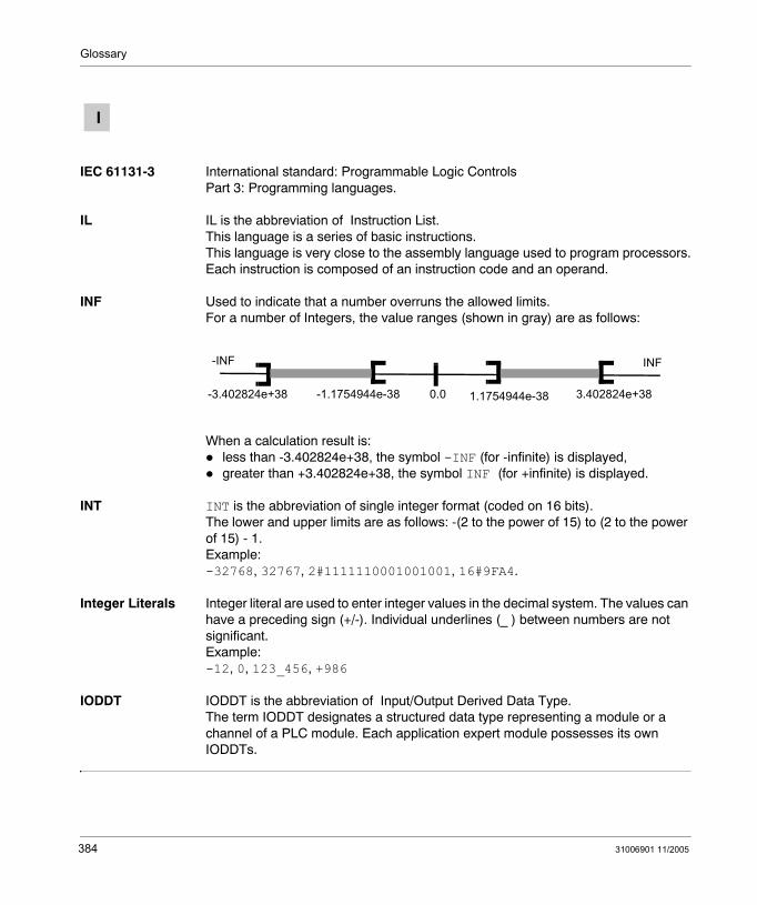
Glossary
IEC 61131-3 International standard: Programmable Logic Controls Part 3: Programming languages.
IL IL is the abbreviation of Instruction List.This language is a series of basic instructions. This language is very close to the assembly language used to program processors.Each instruction is composed of an instruction code and an operand.
INF Used to indicate that a number overruns the allowed limits. For a number of Integers, the value ranges (shown in gray) are as follows:
When a calculation result is: less than -3.402824e+38, the symbol -INF (for -infinite) is displayed,greater than +3.402824e+38, the symbol INF (for +infinite) is displayed.
INT INT is the abbreviation of single integer format (coded on 16 bits). The lower and upper limits are as follows: -(2 to the power of 15) to (2 to the power of 15) - 1.Example:-32768, 32767, 2#1111110001001001, 16#9FA4.
Integer Literals Integer literal are used to enter integer values in the decimal system. The values can have a preceding sign (+/-). Individual underlines (_ ) between numbers are not significant.Example:-12, 0, 123_456, +986
IODDT IODDT is the abbreviation of Input/Output Derived Data Type. The term IODDT designates a structured data type representing a module or a channel of a PLC module. Each application expert module possesses its own IODDTs.
I
-3.402824e+38 3.402824e+38-1.1754944e-38 1.1754944e-380.0
INF-INF
384 31006901 11/2005
Glossary
Keyword A keyword is a unique combination of characters used as a syntactical programming language element (See annex B definition of the IEC standard 61131-3. All the key words used in Unity Pro and of this standard are listed in annex C of the IEC standard 61131-3. These keywords cannot be used as identifiers in your program (names of variables, sections, DFB types, etc.)).
LD LD is the abbreviation of Ladder Diagram. LD is a programming language, representing the instructions to be carried out in the form of graphic diagrams very close to a schematic electrical diagram (contacts, coils, etc.).
Located variables
A located variable is a variable for which it is possible to know its position in the PLC memory. For example, the variable Water_pressure, is associated with%MW102. Water_pressure is said to be localized.
Multiple Token Operating mode of an SFC. In multitoken mode, the SFC may possess several active steps at the same time.
K
L
M
31006901 11/2005 385
Glossary
Naming conventions (Identifier)
An identifier is a sequence of letters, numbers and underlines beginning with a letter or underline (e.g. name of a function block type, an instance, a variable or a section). Letters from national character sets (e.g: ö,ü, é, õ) can be used except in project and DFB names. Underlines are significant in identifiers; e.g. A_BCD and AB_CD are interpreted as different identifiers. Multiple leading underlines and consecutive underlines are invalid.Identifiers cannot contain spaces. Not case sensitive; e.g. ABCD and abcd are interpreted as the same identifier. According to IEC 61131-3 leading digits are not allowed in identifiers. Nevertheless, you can use them if you activate in dialog Tools → Project settings in tab Language extensions the ceck box Leading digits.Identifiers cannot be keywords.
NAN Used to indicate that a result of an operation is not a number (NAN = Not A Number).Example: calculating the square root of a negative number.
Network There are two meanings for Network.In LD: A network is a set of interconnected graphic elements. The scope of a network is local to the program organization unit (section) in which the network is located.With communication expert modules: A network is a group of stations which communicate among one another. The term network is also used to define a group of interconnected graphic elements. This group forms then a part of a program which may be composed of a group of networks.
N
Note: The IEC 559 standard defines two classes of NAN: quiet NAN (QNAN) and signaling NaN (SNaN) QNAN is a NAN with the most significant fraction bit set and a SNAN is a NAN with the most significant fraction bit clear (Bit number 22). QNANs are allowed to propagate through most arithmetic operations without signaling an exception. SNAN generally signal an invalid-operation exception whenever they appear as operands in arithmetic operations (See %SW17 and %S18).
386 31006901 11/2005
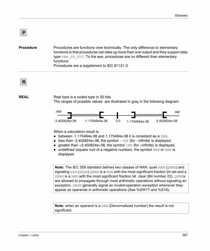
Glossary
Procedure Procedures are functions view technically. The only difference to elementary functions is that procedures can take up more than one output and they support data type VAR_IN_OUT. To the eye, procedures are no different than elementary functions. Procedures are a supplement to IEC 61131-3.
REAL Real type is a coded type in 32 bits.The ranges of possible values are illustrated in gray in the following diagram:
When a calculation result is: between -1.175494e-38 and 1.175494e-38 it is considerd as a DEN,less than -3.402824e+38, the symbol -INF (for - infinite) is displayed,greater than +3.402824e+38, the symbol INF (for +infinite) is displayed,undefined (square root of a negative number), the symbol NAN or NAN is displayed.
P
R
Note: The IEC 559 standard defines two classes of NAN: quiet NAN (QNAN) and signaling NaN (SNaN) QNAN is a NAN with the most significant fraction bit set and a SNAN is a NAN with the most significant fraction bit clear (Bit number 22). QNANs are allowed to propagate through most arithmetic operations without signaling an exception. SNAN generally signal an invalid-operation exception whenever they appear as operands in arithmetic operations (See %SW17 and %S18).
Note: when an operand is a DEN (Denormalized number) the result is not significant.
-3.402824e+38 3.402824e+38-1.1754944e-38 1.1754944e-380.0
INF-INF
31006901 11/2005 387
Glossary
Real Literals An literal real value is a number expressed in one or more decimals.Example:-12.0, 0.0, +0.456, 3.14159_26
Real Literals with Exponent
An Literal decimal value can be expressed using standard scientific notation. The representation is as follows: mantissa + exponential.Example:-1.34E-12 or -1.34e-121.0E+6 or 1.0e+61.234E6 or 1.234e6
SFC SFC is the abbreviation of Sequential Function Chart.SFC enables the operation of a sequential automation device to be represented graphically and in a structured manner. This graphic description of the sequential behavior of an automation device, and the various situations which result from it, is performed using simple graphic symbols.
Single Token Operating mode of an SFC chart for which only a single step can be active at any one time.
ST ST is the abbreviation of Structured Text language.Structured Text language is an elaborated language close to computer programming languages. It enables you to structure series of instructions.
STRING A variable of the type STRING is an ASCII standard character string. A character string has a maximum length of 65534 characters.
TIME The type TIME expresses a duration in milliseconds. Coded in 32 bits, this type
makes it possible to obtain periods from 0 to 2 32-1 milliseconds.The units of type TIME are the following: the days (d), the hours (h), the minutes (m), the seconds (s) and the milliseconds (ms). A literal value of the type TIME is represented by a combination of previous types preceded by T#, t#, TIME# or time#.Examples: T#25h15m, t#14.7S, TIME#5d10h23m45s3ms
S
T
388 31006901 11/2005
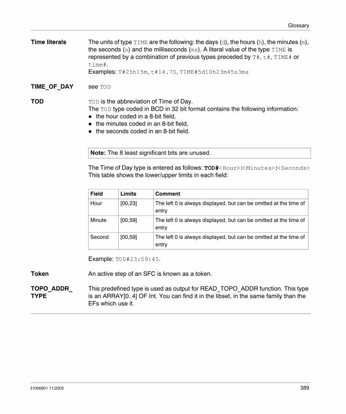
Glossary
Time literals The units of type TIME are the following: the days (d), the hours (h), the minutes (m), the seconds (s) and the milliseconds (ms). A literal value of the type TIME is represented by a combination of previous types preceded by T#, t#, TIME# or time#.Examples: T#25h15m, t#14.7S, TIME#5d10h23m45s3ms
TIME_OF_DAY see TOD
TOD TOD is the abbreviation of Time of Day.The TOD type coded in BCD in 32 bit format contains the following information:
the hour coded in a 8-bit field,the minutes coded in an 8-bit field,the seconds coded in an 8-bit field.
The Time of Day type is entered as follows: TOD#<Hour>:<Minutes>:<Seconds>This table shows the lower/upper limits in each field:
Example: TOD#23:59:45.
Token An active step of an SFC is known as a token.
TOPO_ADDR_TYPE
This predefined type is used as output for READ_TOPO_ADDR function. This type is an ARRAY[0..4] OF Int. You can find it in the libset, in the same family than the EFs which use it.
Note: The 8 least significant bits are unused.
Field Limits Comment
Hour [00,23] The left 0 is always displayed, but can be omitted at the time of entry
Minute [00,59] The left 0 is always displayed, but can be omitted at the time of entry
Second [00,59] The left 0 is always displayed, but can be omitted at the time of entry
31006901 11/2005 389
Glossary
UDINT UDINT is the abbreviation of Unsigned Double Integer format (coded on 32 bits) unsigned. The lower and upper limits are as follows: 0 to (2 to the power of 32) - 1.Example:0, 4294967295, 2#11111111111111111111111111111111, 8#37777777777, 16#FFFFFFFF.
UINT UINT is the abbreviation of Unsigned integer format (coded on 16 bits). The lower and upper limits are as follows: 0 to (2 to the power of 16) - 1.Example:0, 65535, 2#1111111111111111, 8#177777, 16#FFFF.
Unlocated variable
An unlocated variable is a variable for which it is impossible to know its position in the PLC memory. A variable which have no address assigned is said to be unlocated.
Variable Memory entity of the type BOOL, WORD, DWORD, etc., whose contents can be modified by the program during execution.
U
V
390 31006901 11/2005
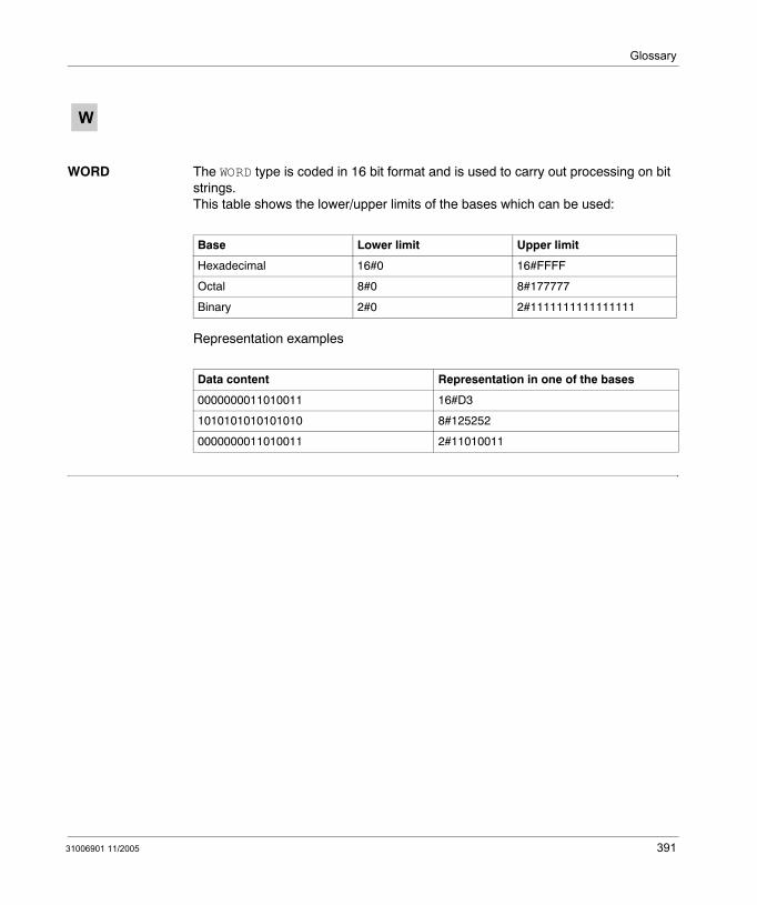
Glossary
WORD The WORD type is coded in 16 bit format and is used to carry out processing on bit strings.This table shows the lower/upper limits of the bases which can be used:
Representation examples
W
Base Lower limit Upper limit
Hexadecimal 16#0 16#FFFF
Octal 8#0 8#177777
Binary 2#0 2#1111111111111111
Data content Representation in one of the bases
0000000011010011 16#D3
1010101010101010 8#125252
0000000011010011 2#11010011
31006901 11/2005 391

Glossary
392 31006901 11/2005
CBAIndex
Symbols%S10, 369%S11, 369%S12, 369%S13, 369%S15, 370%S16, 370%S17, 370%S18, 371%S19, 371%S20, 371%S21, 371%S9, 369%SW12, 372%SW13, 372%SW14, 372%SW15, 372%SW16, 372%SW17, 373%SW18, 373%SW19, 373
Numerics100MSCOUNTER, 3731RSTSCANRUN, 3691RSTTASKRUN, 371
31006901 11/2005
AAdd 16-bit
LL_AD16, 53Addition
LL_ADD, 57
BBit Control
LL_NBIT, 159Bit Rotate (%I - %M)
LL_BROT_10, 127Bit Rotate (%I - %MW)
LL_BROT_14, 131Bit Rotate (%IW - %M)
LL_BROT_30, 135Bit Rotate (%IW - %MW)
LL_BROT_34, 139Bit Rotate (%M - %M)
LL_BROT_00, 119Bit Rotate (%M - %MW)
LL_BROT_04, 123Bit Rotate (%MW - %M)
LL_BROT_40, 143Bit Rotate (%MW - %MW)
LL_BROT_44, 147Block Move (%I - %M)
LL_BLKM_10, 259Block Move (%I - %MW)
LL_BLKM_14, 263Block Move (%IW - %M)
LL_BLKM_30, 267
393
Index
Block Move (%IW - %MW)LL_BLKM_34, 271
Block Move (%M - %M)LL_BLKM_00, 251
Block Move (%M - %MW)LL_BLKM_04, 255
Block Move (%MW - %M)LL_BLKM_40, 275
Block Move (%MW - %MW)LL_BLKM_44, 279
Block to TableLL_BLKT, 283
Block types, 16
CCARRY, 370Conditional FFB Call, 21counters, 25counters and timers
LL_DCTR, 27LL_T001, 31LL_T01, 35LL_T1, 39LL_T1MS, 43LL_UCTR, 47
DDerived function block, 16Divide
LL_DIV, 61Divide 16-Bit
LL_DV16, 65Down Counter
LL_DCTR, 27
EElementary Function, 16Elementary function block, 16EN, 20ENO, 20Exclusive OR (%I - %M)
LL_XOR_10, 225
394
Exclusive OR (%I - %MW)LL_XOR_14, 229
Exclusive OR (%IW - %M)LL_XOR_30, 233
Exclusive OR (%IW - %MW)LL_XOR_34, 237
Exclusive OR (%M - %M)LL_XOR_00, 217
Exclusive OR (%M - %MW)LL_XOR_04, 221
Exclusive OR (%MW - %M)LL_XOR_40, 241
Exclusive OR (%MW - %MW)LL_XOR_44, 245
FFirst In (%I - %MW)
LL_FIN_14, 291First In (%IW - %MW)
LL_FIN_34, 295First In (%M - %MW)
LL_FIN_04, 287First In (%MW - %MW)
LL_FIN_44, 299First Out (%MW - %M)
LL_FOUT_40, 303First Out (%MW - %MW)
LL_FOUT_44, 307FLOATSTAT, 373
IINDEXOVF, 371IOERR, 369IOERRTSK, 370
LLL_AD16, 53LL_ADD, 57LL_AND_00, 87LL_AND_04, 91LL_AND_10, 95LL_AND_14, 99
31006901 11/2005
Index
LL_AND_30, 103LL_AND_34, 107LL_AND_40, 111LL_AND_44, 115LL_BLKM_00, 251LL_BLKM_04, 255LL_BLKM_10, 259LL_BLKM_14, 263LL_BLKM_30, 267LL_BLKM_34, 271LL_BLKM_40, 275LL_BLKM_44, 279LL_BLKT, 283LL_BROT_00, 119LL_BROT_04, 123LL_BROT_10, 127LL_BROT_14, 131LL_BROT_30, 135LL_BROT_34, 139LL_BROT_40, 143LL_BROT_44, 147LL_DCTR, 27LL_DIV, 61LL_DV16, 65LL_FIN_04, 287LL_FIN_14, 291LL_FIN_34, 295LL_FIN_44, 299LL_FOUT_40, 303LL_FOUT_44, 307LL_MBIT_X0, 151LL_MBIT_X4, 155LL_MU16, 69LL_MUL, 73LL_NBIT, 159LL_NCBT, 161LL_NOBT, 163LL_OR_00, 165LL_OR_04, 169LL_OR_10, 173LL_OR_14, 177LL_OR_30, 181LL_OR_34, 185LL_OR_40, 189LL_OR_44, 193LL_R_TO_T_04, 311
31006901 11/2005
LL_R_TO_T_14, 315LL_R_TO_T_34, 319LL_R_TO_T_44, 323LL_RBIT, 197LL_SBIT, 199LL_SENS_X0, 201LL_SENS_X1, 205LL_SENS_X3, 209LL_SENS_X4, 213LL_SU16, 77LL_SUB, 81LL_T_TO_R_04, 327LL_T_TO_R_14, 331LL_T_TO_R_34, 335LL_T_TO_R_44, 339LL_T_TO_T_04, 343LL_T_TO_T_14, 347LL_T_TO_T_34, 351LL_T_TO_T_44, 355LL_T001, 31LL_T01, 35LL_T1, 39LL_T1MS, 43LL_TBLK, 359LL_UCTR, 47LL_XOR_00, 217LL_XOR_04, 221LL_XOR_10, 225LL_XOR_14, 229LL_XOR_30, 233LL_XOR_34, 237LL_XOR_40, 241LL_XOR_44, 245Logical AND (%I - %M)
LL_AND_10, 95Logical AND (%I - %MW)
LL_AND_14, 99Logical AND (%IW - %M)
LL_AND_30, 103Logical AND (%IW - %MW)
LL_AND_34, 107Logical AND (%M - %M)
LL_AND_00, 87Logical AND (%M - %MW)
LL_AND_04, 91
395
Index
Logical AND (%MW - %M)LL_AND_40, 111
Logical AND (%MW - %MW)LL_AND_44, 115
Logical OR (%I - %M)LL_OR_10, 173
Logical OR (%I - %MW)LL_OR_14, 177
Logical OR (%IW - %M)LL_OR_30, 181
Logical OR (%IW - %MW)LL_OR_34, 185
Logical OR (%M - %M)LL_OR_00, 165
Logical OR (%M - %MW)LL_OR_04, 169
Logical OR (%MW - %M)LL_OR_40, 189
Logical OR (%MW - %MW)LL_OR_44, 193
MMath
LL_AD16, 53LL_ADD, 57LL_DIV, 61LL_DV16, 65LL_MU16, 69LL_MUL, 73LL_SU16, 77LL_SUB, 81
math, 51
396
MatrixLL_AND_00, 87LL_AND_04, 91LL_AND_10, 95LL_AND_14, 99LL_AND_30, 103LL_AND_34, 107LL_AND_40, 111LL_AND_44, 115LL_BROT_00, 119LL_BROT_04, 123LL_BROT_10, 127LL_BROT_14, 131LL_BROT_30, 135LL_BROT_34, 139LL_BROT_40, 143LL_BROT_44, 147LL_MBIT_X0, 151LL_MBIT_X4, 155LL_NBIT, 159LL_NCBT, 161LL_NOBT, 163LL_OR_00, 165LL_OR_04, 169LL_OR_10, 173LL_OR_14, 177LL_OR_30, 181LL_OR_34, 185LL_OR_40, 189LL_OR_44, 193LL_RBIT, 197LL_SBIT, 199LL_SENS_X0, 201LL_SENS_X1, 205LL_SENS_X3, 209LL_SENS_X4, 213LL_XOR_00, 217LL_XOR_04, 221LL_XOR_10, 225LL_XOR_14, 229LL_XOR_30, 233LL_XOR_34, 237LL_XOR_40, 241LL_XOR_44, 245
matrix, 85
31006901 11/2005
Index
Modify Bit (%M)LL_MBIT_X0, 151
Modify Bit (%MW)LL_MBIT_X4, 155
MoveLL_BLKM_00, 251LL_BLKM_04, 255LL_BLKM_10, 259LL_BLKM_14, 263LL_BLKM_30, 267LL_BLKM_34, 271LL_BLKM_40, 275LL_BLKM_44, 279LL_BLKT, 283LL_FIN_04, 287LL_FIN_14, 291LL_FIN_34, 295LL_FIN_44, 299LL_FOUT_40, 303LL_FOUT_44, 307LL_R_TO_T_04, 311LL_R_TO_T_14, 315LL_R_TO_T_34, 319LL_R_TO_T_44, 323LL_T_TO_R_04, 327LL_T_TO_R_14, 331LL_T_TO_R_34, 335LL_T_TO_R_44, 339LL_T_TO_T_04, 343LL_T_TO_T_14, 347LL_T_TO_T_34, 351LL_T_TO_T_44, 355LL_TBLK, 359
move, 249Multiply
LL_MUL, 73Multiply 16-Bit
LL_MU16, 69
NNormally Closed Bit
LL_NCBT, 161Normally Open Bit
LL_NOBT, 163
31006901 11/2005
OOne Hundredth Second Timer
LL_T001, 31One Millisecond Timer
LL_T1MS, 43One Second Timer
LL_T1, 39One Tenth Second Timer
LL_T01, 35OSCOMMPATCH, 372OSCOMMVERS, 372OSINTVERS, 372OUTDIS, 369OVERFLOW, 371OVERRUN, 371
PPLCRUNNING, 369Procedure, 16
RRegister to Table (%I - %MW)
LL_R_TO_T_14, 315Register to Table (%IW - %MW)
LL_R_TO_T_34, 319Register to Table (%M - %MW)
LL_R_TO_T_04, 311Register to Table (%MW - %MW)
LL_R_TO_T_44, 323Reset Bit
LL_RBIT, 197
SSense (%I)
LL_SENS_X1, 205Sense (%IW)
LL_SENS_X3, 209Sense (%M)
LL_SENS_X0, 201Sense (%MW)
LL_SENS_X4, 213
397
Index
Set BitLL_SBIT, 199
STRINGERROR, 370Subtract 16-bit
LL_SU16, 77Subtraction
LL_SUB, 81
TTable to Block
LL_TBLK, 359Table to Register (%I - %MW)
LL_T_TO_R_14, 331Table to Register (%IW - %MW)
LL_T_TO_R_34, 335Table to Register (%M - %MW)
LL_T_TO_R_04, 327Table to Register (%MW - %MW)
LL_T_TO_R_44, 339Table to Table (%I - %MW)
LL_T_TO_T_14, 347Table to Table (%IW - %MW)
LL_T_TO_T_34, 351Table to Table (%M - %MW)
LL_T_TO_T_04, 343Table to Table (%MW - %MW)
LL_T_TO_T_44, 355timers, 25
UUnconditional FFB Call, 21Up Counter
LL_UCTR, 47UTWPORTADDR, 372
WWDG, 369
XXWAYNETWADDR, 372
398
31006901 11/2005