Embed Size (px)
Citation preview

Surgical techniqueMeasured resection approach
Unity Knee™
Think isometry Feel balance
Corin would like to thank Professor J Bellemans, Professor J Victor, Professor R Wittenberg, Dr T Paszicsnyek, Dr S Kreuzer and Mr A Toms for their contribution to this surgical technique.
ContentsOperative summary 4
Pre-operative assessment 5
Instrumentation rationale 5
Operative technique 6
1. Approach 6
2. Initial tibial preparation 6
3. Tibial resection 7
4. Initial femoral preparation 8
5. Varus/valgus alignment 8
6. Distal femoral resection 9
7. Rotational alignment and femoral sizing 10
8. 4-in-1 femoral resection 11
9. Balancing flexion-extension gaps 12
10. Initial femoral trial 13
11. Final tibial preparation 15
12. Final femoral preparation 16
13. Patella resection 16
14. Patella sizing 17
15. Patella drill 17
16. Patella trial 17
17. Trial reduction 17
18. Insertion of definitive implants 18
Indications 19
Contraindications 19
Device description 19
Unity Knee™ femoral sizing chart 19
Ordering information 20
Sizing guide 23
2

Think isometry Feel balanceUnity Knee™
3 |Responsible Innovation

Operative summary
a. Initial tibial preparation b. Tibial resection c. Initial femoral preparation d. Femoral resection
e. Femoral sizing f. 4-in-1 femoral resection g. Balancing flexion/extension gaps h. Femoral trial
4

i. Final tibial preparation j. Patella preparation
k. Trial reduction l. Definitive implant insertion
Pre-operative assessmentPre-operative long leg standing radiographs are recommended to determine both the mechanical and anatomical axes of the limb. It is generally recognised that the joint is reconstructed with a standing knee valgus of between 5° and 9° and the tibial component at 90° to the anatomic axis in the coronal plane.
Radiographic templates can also be used to get an indication of the probable implant size and to determine whether additional bone support is required in the form of bone grafts. A lateral template should be used to give an indication of femoral sizing. The A-P size is critical to the restoration of normal knee kinematics and quadriceps function. The A-P template can be overlaid on the A-P radiograph to check adequate coverage of the medial and lateral condyles and the probable size of the femoral prosthesis.
Instrumentation rationaleThe surgical objective of the Unity Knee™ instrumentation for total knee arthroplasty is to place the prosthetic components in an anatomical and neutral position with respect to the mechanical axis of the knee joint, whilst maintaining stability throughout the full range of knee flexion.
It is important that a 1.27mm saw blade is utilised with this system, as the use of thinner blades will compromise the accuracy of the cuts.
Note: The minimum recommended thickness of insert is the 9mm tibial bearing which has a minimum thickness of 6mm in the load bearing area as per BS EN ISO 21536:2009.
5 |Responsible Innovation

Operative technique
1. Approach A standard medial parapatellar approach can be used in the majority of cases.
Prepare and drape the limb to allow the centre of the ankle and hip to be palpated during the course of the procedure as this may be necessary when using EM alignment instrumentation. A thigh tourniquet may be used but is not mandatory.
Dissect soft tissues until the quadriceps and patella tendon are clearly exposed. Dislocate or evert the patella for complete exposure of the joint.
2. Initial tibial preparationWith the knee in 90° of flexion or more, the ankle clamp arms of the EM tibial alignment guide are opened and placed around the ankle. The ankle clamp can be locked into an open position for ease of placement and released by depressing the quick release button. Flexion-extension axis is considered to be correct when the long axis of the assembly is parallel to the mid-coronal plane of the tibia. At this setting a 3° slope is built into the tibial cutting block. To adjust the tibial slope further the EM guide can be shifted on the AP arm of the ankle clamp by using the cam lock lever.
For varus/valgus alignment the medial/lateral offset can be adjusted by depressing the ML button and shifting the assembly until the shaft is pointing towards the medial third of the tibial tuberosity. Usually if the foot is in neutral at this position, the anterior tongue of the ankle clamp points to the
centre of the ankle joint which is generally in line with the second meta-tarsal.
Once the flexion-extension and varus/valgus settings are achieved, the first proximal spike is tapped into the tibial spine to provide varus/valgus and anterior/posterior stability, whilst still allowing rotational correction of the jig. The left or right tibial resection block is located against the tibial plateau by adjusting the AP button on the proximal tibial spike arm. Once the rotational alignment is confirmed, the second spike is engaged to lock in the correct position of the tibial jig. The EM tibial jig has both macro and micro adjustment features to allow for accurate resection depth. The micro-adjustment feature operates at 1mm increments allowing for small adjustments to tibial resection levels.
Figure A : EM tibial assembly with proximal spike attachment
Figure B: EM tibial assembly with proximal spike removed
AP movement button
Tibial micro-adjuster
Tibial micro-adjuster release button
Tibial spike lock
Ankle clamp
Medial/lateral adjustment button
Cam lock
Cam lock
Quick release button
6

Note: The EM tibial spike is modular and can be removed should the surgeon want to use the guide without the spike. See Figure A and B, page 6.
An adjustable stylus is also provided which allows resection levels from 2-10mm depending on whether the reference point is the most worn or least worn condyle. This stylus is positioned into the superior hole on the tibial resection block and the tip of the stylus allowed to rest in the deepest point of the tibial plateau. Once the position of the tibial cutting block and the resection level are confirmed, the cutting block is fixed into position.
Note: The minimum polyethylene and tibial tray thickness of the Unity Knee™ is 9mm
3. Tibial resection The tibial resection block is pinned to the proximal tibia with two straight pins located in ‘0’ holes positioned along the same line. This will allow for resection level adjustment if necessary. As an additional check, the EM reference guide can be placed within the distal holes of the tibial block and EM alignment rod used to verify alignment.
Once the tibial alignment checks are complete, collared pins are inserted into the angled holes to secure the guide in place for the saw cut. The angel wing can be used to assess the tibial resection depth and slope.
The tibia is now resected through the tibial guide slot.
Note: Should the surgeon prefer to use non-slotted resection, the proximal surface of the tibial block allows 3mm less resection.
When using a cruciate retaining (CR) prosthesis it is recommended that the EM tibial guide arm is adjusted to maintain an anatomic posterior tibial slope. When using a posterior stabilised (PS) prosthesis, a 3° tibial slope can be maintained by ensuring the tibial guide arm is parallel to the tibial shaft in the sagittal plane.
The resected tibia should be checked to confirm that the cut is flat and that an accurate posterior slope has been achieved.
If the surgeon chooses to retain the posterior cruciate ligament, care should be taken when resecting the proximal tibia to preserve the PCL attachment.
3° posterior slope built into the cutting block
Set stylus to accomodate 9mm tibial gap
7 |Responsible Innovation

4. Initial femoral preparationThe IM canal drill is used to penetrate the cortex of the distal femur. This drill includes a sharp proximal tip for improved accuracy of femoral canal alignment. The correct entry point is in line with the medullary canal, medial to the mid point between the distal condyles and 10mm anterior to the origin of the posterior cruciate ligament.
The IM rod is assembled with the T-handle by pulling the locking collar towards the handle. The assembly is then pushed into the canal only as far as the fluted section.
The T-handle is removed.
5. Varus/valgus alignment The valgus angle to be created is determined from pre-operative templating. The femoral distal alignment jig has varus/valgus settings from 0-9° for both left and right knees. The appropriate varus/valgus setting is chosen from the selection. The distal femoral resection block attaches to the distal femoral alignment jig via the resection depth adjustment drum. For a standard distal femoral resection the drum should be set at '0', which equates to the thickness of the femoral implant (9mm). Once the varus/valgus setting and depth of resection is confirmed, the distal femoral alignment jig is slid onto the IM rod until the distal plate rests against one or both distal femoral condyles, and the distal resection block assembly shifted in an AP
direction so that the resection block rests against the anterior femoral cortex.
The IM femoral jig can also be locked to the IM rod using the cam lock stabilising the jig during assembly and resection.
In order to ensure medial joint line preservation and MCL isometry, it is recommended that any bone loss be taken into account with adjustments in depth of resection prior to locking the distal block in situ.
Distal resection block locking knob
Resection depth adjustment drum
'0' setting equates to 9mm thickness of femoral implant
8

6. Distal femoral resectionOnce the varus/valgus setting and resection depth are confirmed, the distal femoral cutting block can be pinned onto the anterior cortex of the femur with two straight pins in the ‘0’ hole position. The distal femoral alignment jig is completely removed by rotating the locking knob to the 'unlocked' setting and pulling the resection depth adjustment drum assembly anteriorly, disengaging the distal femoral alignment jig from the distal femoral block. The T-handle can then be used to remove the distal femoral alignment jig and the IM rod. Use the camlock on the distal femoral jig to lock against the IM rod during removal.
To confirm IM alignment, the EM alignment guide and EM rod can be used connecting to the distal holes of the distal femoral resection block. The femoral alignment rods assemble together and allow for full leg alignment. The angel wing can also be used to confirm depth of resection. If more resection is required, reposition the distal resection guide by moving it proximally onto the next set of pin holes.
Once the surgeon is satisfied with the position and orientation of the distal resection block, collared pins can be used in the angled holes to secure the block and distal resection can be conducted.
9 |Responsible Innovation
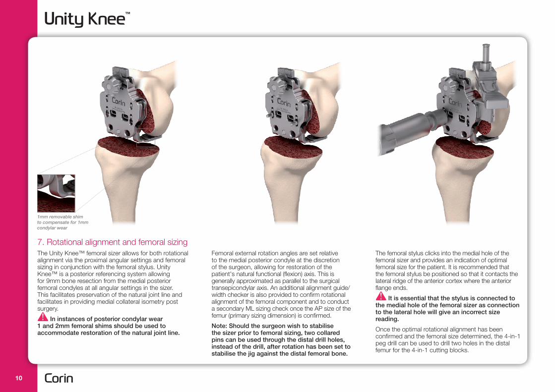
7. Rotational alignment and femoral sizingThe Unity Knee™ femoral sizer allows for both rotational alignment via the proximal angular settings and femoral sizing in conjunction with the femoral stylus. Unity Knee™ is a posterior referencing system allowing for 9mm bone resection from the medial posterior femoral condyles at all angular settings in the sizer. This facilitates preservation of the natural joint line and facilitates in providing medial collateral isometry post surgery.
In instances of posterior condylar wear 1 and 2mm femoral shims should be used to accommodate restoration of the natural joint line.
Femoral external rotation angles are set relative to the medial posterior condyle at the discretion of the surgeon, allowing for restoration of the patient's natural functional (flexion) axis. This is generally approximated as parallel to the surgical transepicondylar axis. An additional alignment guide/width checker is also provided to confirm rotational alignment of the femoral component and to conduct a secondary ML sizing check once the AP size of the femur (primary sizing dimension) is confirmed.
Note: Should the surgeon wish to stabilise the sizer prior to femoral sizing, two collared pins can be used through the distal drill holes, instead of the drill, after rotation has been set to stabilise the jig against the distal femoral bone.
The femoral stylus clicks into the medial hole of the femoral sizer and provides an indication of optimal femoral size for the patient. It is recommended that the femoral stylus be positioned so that it contacts the lateral ridge of the anterior cortex where the anterior flange ends.
It is essential that the stylus is connected to the medial hole of the femoral sizer as connection to the lateral hole will give an incorrect size reading.
Once the optimal rotational alignment has been confirmed and the femoral size determined, the 4-in-1 peg drill can be used to drill two holes in the distal femur for the 4-in-1 cutting blocks.
1mm removable shim to compensate for 1mm condylar wear
10

8. 4-in-1 femoral resection To carry out 4-in-1 femoral resection, two instrument options are available. Option A blocks feature a +/- 1 and +/-2 A/P shift button and option B blocks feature +/- 1.5mm drill holes to achieve A/P shift.
Option A) Modular cutting block
The appropriate size 4-in-1 femoral cutting block is positioned onto the distal femur ensuring it sits flush against the distal femoral resection plane. The angel wing can be used at this point to confirm anterior and posterior resection levels. In instances where further stability of the block is required, collared pins can be used to secure the block in situ.
Unity Knee™ recommends a posterior referencing philosophy to confirm preservation of
posterior condylar offset. For this it is crucial that the 4-in-1 block button is maintained at the '0' setting as this will result in a consistent 9mm posterior bone resection from the posterior medial femoral condyle. Shifting the button to '+1' or '+2' setting results in a 1, or 2mm anterior shift of the flexion joint line, whilst shifting the button to '-1', or '-2' setting will result in a 1, or 2mm posterior shift of the flexion joint line.
Option B) Monoblock cutting block
The cutting block can be introduced by directly impacting the front face of the block or by assembling the cutting block with the extraction tool and modular handle. If impacting directly on the front face, care should be taken to do so centrally to avoid uneven seating of the block.
To shift the monoblock cutting block +/- 1.5mm A/P, the 4-in-1 drill should be used to drill new holes to allow for the desired shift of the cutting block. At this stage the cutting block should be removed using the extraction tool and re-introduced onto the new 1.5mm anterior or posterior shift holes and collared pins used to secure the block.
Note: If when drilling the new holes additional block stability is required, the pin hole array should be used to stabilise the block by pinning two collarless pins in the middle shift position. The cutting block should be removed and re-positioned and two angled collared pins inserted to stabilise the block.
Once the shifted 4-in-1 block position has been confirmed and stabilised, the two non-collared pins in
A) B)
Initial pin position
Pin position following 1.5mm anterior shift
11 |Responsible Innovation

9. Balancing flexion-extension gapsTo carry out flexion-extension gap check, two instrument options are available.
A) Adjustable gap checker
The adjustable gap checker is set to the appropriate height and inserted into the joint space both in flexion and extension to confirm balanced flexion and extension gaps have been achieved.
The adjustable gap checker is not intended to be used as a ligament tensioner and should only be used as a gap checker. A separate ligament tensioner is available should the surgeon wish to conduct a ligament balancing technique.
A) Adjustable gap checker
Top surface = anterior cut of size above
Size 5
Size 6
Top surface = anterior cut of size above
Size 5Size 6
the pin hole array should be removed from the pin hole array to allow for resection.
The anterior, posterior, anterior chamfer and posterior chamfer femoral cuts are now performed through the 4-in-1. At this stage, it may be necessary to clear behind the posterior condyles, especially in larger knees, so as to remove any condyle bone remnants or osteophytes which could restrict flexion.
For 4-in-1 cutting block removal, the slap hammer can be slipped onto the grooves of the extraction feature in the modular blocks, or assembled with the extraction tool and slid onto the central grooves in the monoblock cutting blocks.
Note: If the femoral size reading is in between the recommended Unity Knee™ sizes the preference should be to down-size the component so as to avoid over-stuffing the patella-femoral joint. The Unity Knee™ femur includes a 7° anterior flange which reduces the risk of notching when downsizing.
Should there be any concerns on sizing once the smaller 4-in-1 block is in position, the top surface (non-slotted) of the block will allow for the same anterior resection as a size above – e.g. the top surface of a size 5 cutting block creates the same anterior cut as a size 6 cutting block. This allows the surgeon to verify if the larger size is the better option and change the cutting block prior to resecting through the slots of a smaller block.
12
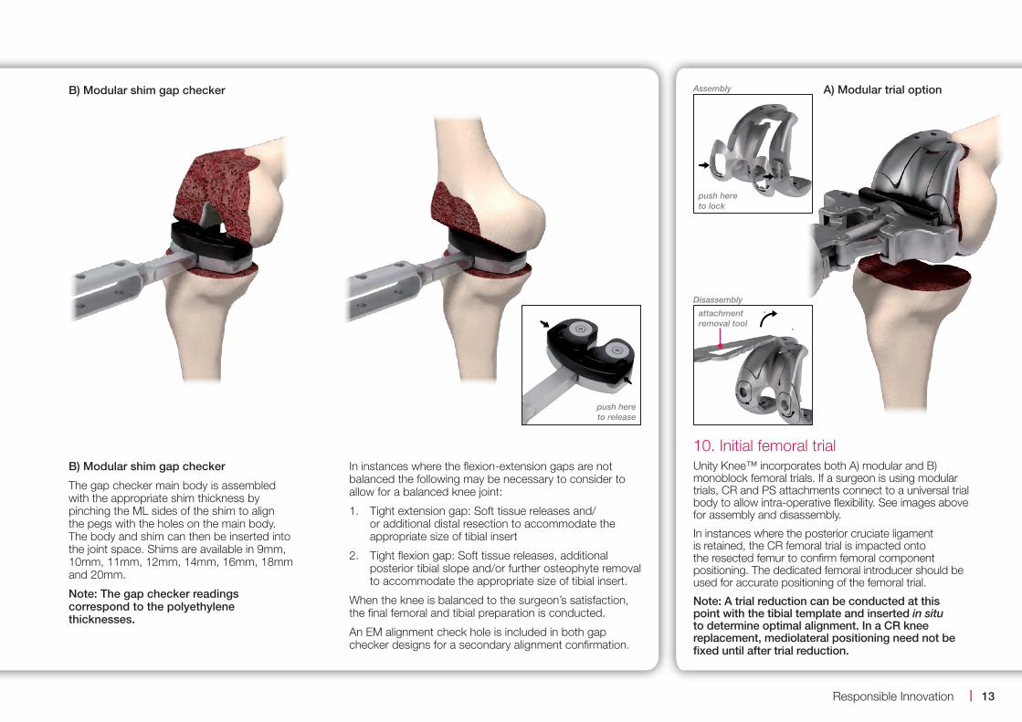
B) Modular shim gap checker
The gap checker main body is assembled with the appropriate shim thickness by pinching the ML sides of the shim to align the pegs with the holes on the main body. The body and shim can then be inserted into the joint space. Shims are available in 9mm, 10mm, 11mm, 12mm, 14mm, 16mm, 18mm and 20mm.
Note: The gap checker readings correspond to the polyethylene thicknesses.
10. Initial femoral trialUnity Knee™ incorporates both A) modular and B) monoblock femoral trials. If a surgeon is using modular trials, CR and PS attachments connect to a universal trial body to allow intra-operative flexibility. See images above for assembly and disassembly.
In instances where the posterior cruciate ligament is retained, the CR femoral trial is impacted onto the resected femur to confirm femoral component positioning. The dedicated femoral introducer should be used for accurate positioning of the femoral trial.
Note: A trial reduction can be conducted at this point with the tibial template and inserted in situ to determine optimal alignment. In a CR knee replacement, mediolateral positioning need not be fixed until after trial reduction.
Assembly
push here to lock
Disassembly
attachment removal tool
push here to release
A) Modular trial optionB) Modular shim gap checker
In instances where the flexion-extension gaps are not balanced the following may be necessary to consider to allow for a balanced knee joint:
1. Tight extension gap: Soft tissue releases and/or additional distal resection to accommodate the appropriate size of tibial insert
2. Tight flexion gap: Soft tissue releases, additional posterior tibial slope and/or further osteophyte removal to accommodate the appropriate size of tibial insert.
When the knee is balanced to the surgeon’s satisfaction, the final femoral and tibial preparation is conducted.
An EM alignment check hole is included in both gap checker designs for a secondary alignment confirmation.
13 |Responsible Innovation

Confirm the PS box cut guide is assembled in the correct orientation and fully seated against the femoral trial.
The drill guide should then be disconnected from the box resection guide and the box chisel used to clear any final remnants of bone around the PS box, taking care to ensure the PS femoral attachment is seated fully against the resected femur.
Once the PS box resection has been completed, the PS box resection guide is removed and the modular PS trial attachment is connected to the femoral trial to confirm femoral component seating.
For PS TKA, two options are available:
A) PS box ream and chisel technique (modular femoral trials are required for this technique).
The femoral chain drill guide is assembled with the box resection guide and the femoral trial once the latter has been positioned in situ. The assembly should be pinned in place with collared pins using the anterior pin holes on the femoral trial to stabilise the assembly during the box resection step. The chain drill should be used first.
The femoral trial assembly should be pinned in place prior to box resection to enable accurate bone resection. The most lateral and distal pin holes should be used if possible to pin the trial assembly.
If using a monoblock femoral trial, for trial removal the femoral trial extraction tool should be assembled with the slap hammer and slid onto the grooves on the femoral component.
The femoral trial extraction tool should not be used to introduce or re-position the monoblock femoral trial.
B) Monoblock trial option
14

The tibial template is secured in place using two collared pins. The anterior pin holes on the tibial template can be used to secure the template should the surgeon wish to do so whilst the trial insert is in situ.
The tibial keel punch guide is assembled onto the secured tibial template and tibial stem drill used to create the inital tibial stem hole. The tibial keel punch should be used next for accurate bone removal.
Should the surgeon wish to finalise tibial rotation after trial positioning, a tibial keel plug is available which allows rotational adjustment of the template during trial.
The keel punch handle is then disassembled from the tibial keel punch and the latter left in situ with the tibial template as the tibial tray trial.
11. Final tibial preparationThe tibial template which conforms optimally to the resected proximal tibia should be chosen and assembled with the tibial template handle.
Note: Unity Knee™ allows for 1 up, 1 down sizing across its range – e.g. for a size 4 femur, sizes 3, 4 or 5 tibial trays may be used. However, the tibial insert must be specific to the size of the tibial tray chosen.
Alignment of the tibial template assembly is made by placing it so that the central handle is aligned with the medial third of the tibial tuberosity. Using the EM rod, an extramedullary alignment check may be made ensuring that the rod is parallel to the long axis of the tibia.
B) PS box saw resection guide (both monoblock and modular femoral trials can be used with this technique)
The appropriate sized PS box saw resection guide is selected and positioned onto the resected femur. Utilise the medio-lateral wings to centralise the guide on the distal femur. These medio-lateral wings highlight the width of the femur at that position for each size.
The guide should be pinned in place with collared pins using at least one anterior and one distal pin hole. Femoral box resection is conducted with a reciprocating sawblade resting flush against the guide walls.
15 |Responsible Innovation

13. Patella resection The patella should be firmly grasped with the patella resection guide and the instrument locked in position. The patella depth gauge measures the thickness of patella retained. It is recommended that a minimum of 12mm of bony patella be preserved to facilitate sufficient peg fixation.
Patella callipers have also been provided to confirm thickness of the natural patella and resected patella surfaces.
The patella is resected via the slot in the patella resection guide taking care not to damage the femoral and patella ligaments.
Patella thicknessesSize Dome
thicknessOffset dome thickness
1 7.5mm 8.0mm
2 8.0mm 8.5mm
3 8.5mm 9.0mm
4 9.0mm 9.5mm
5 9.5mm n/a
12. Final femoral preparation The CR or PS trial femur of appropriate size (modular or monoblock) and trial tibial insert of appropriate size (corresponding to the tibial template size) and thickness are inserted into the joint and trial reduction is conducted.
In instances where the CR femur and insert are being used, the mediolateral position of the femoral implant can be confirmed at this stage and the peg drill used to drill through the two holes in the condyles of the CR femoral trial.
In instances where the PS implant is being used femoral holes do not need to be drilled as the PS femoral implant does not have pegs.
16

17. Trial reductionA trial reduction in flexion and extension is performed to confirm that correct balancing of the knee joint has been achieved.
14. Patella sizingTo size the patella, peg drill guides are placed on the resected surface and the appropriate size chosen.
Note: The peg locations in the dome patellas and offset dome patellas have been designed to allow for fine tuning of patella size and type based on thickness and improved patella tracking. Please see table above for size compatibility between the two patella types.
15. Patella drillOnce the correct peg drill guide has been chosen, it is inserted into the drill guide handle, placed on the patella in the orientation shown. The patella drill is then passed through each hole.
Patella peg locationDome patella peg location
Offset dome patella peg location
Size 1,2 is equal to Size 1,2
Size 3,4,5 is equal to Size 3,4
16. Patella trialRemove the patella peg drill guide and place the appropriate trial patella 3-peg dome or 3-peg offset/asymmetric dome patella trial onto the bony surface.
17 |Responsible Innovation

18. Insertion of definitive implants Remove all trial components from each of the bones and prepare the bony surfaces for cement.
Insert the definitive femoral and tibial tray components. The trial tibial insert should be used to pressurise the cement prior to insertion of the definitive tibial insert. The tibial insert impactor should be used to impact the tibial insert, at an approximately 70° angle, onto the tibial tray ensuring secure engagement of the tibial insert.
Note: Particular attention should be paid to clearing cement posteriorly from both the tibia and femur, in the intercondylar area of the femur, and around the patella implant.
To cement the patella, pressure can be applied using the patella pressurisation clamp.
Care should be taken when handling the definitive implants and all polished surfaces should be protected.
The wound is closed according to the surgeon’s usual practice.
The CR tibial insert trials include a modular PS post which should be clicked into place prior to introducing into the joint space. A post removal tool has been provided to support disassembly after surgery.
Disassembly
PS post removal tool
Assembly
18
IndicationsGeneral total knee arthroplasty indications include:
■■ Painful, disabling joint disease of the knee resulting from: degenerative arthritis, rheumatoid arthritis or post-traumatic arthritis
■■ Post-traumatic loss of knee joint configuration and function
■■ Moderate varus, valgus, or flexion deformity in which the ligamentous structures can be returned to adequate function
■■ Revision of previous unsuccessful knee replacement or other procedure, where soft tissue stability is adequate
■■ Fracture of the distal femur and/or proximal tibia that cannot be stabilised by standard fracture management techniques
■■ The posterior stabiIised variant is also indicated for PCL instability requiring implant bearing surface geometries with increased anterior-posterior constraint and absent or non-functioning posterior cruciate ligament
The Unity Knee™ is intended for cemented use, single use only.
Contraindications■■ Severe instability secondary to advanced loss of
osteochondral structure or the absence of collateral ligament integrity
■■ Infection/distant foci of infections
■■ Osteomyelitis, osteoporosis, osteomalacia
■■ Marked bone loss or bone resorption
■■ Metabolic disorders which may impair bone formation
■■ Vascular insufficiency
■■ Muscular atrophy or neuromuscular disease
■■ Allergy to implant material
■■ Severe deformity
Device descriptionUnity Knee™ is a fixed bearing total knee replacement system that consists of a femoral component, tibial insert, tibial tray and all-polyethylene patellar component for use in primary total knee arthroplasty. The Unity Knee™ is provided in two variants, cruciate retaining (CR) and posterior stabilised (PS). The Unity Knee™ CR variant is intended for use in instances where the posterior cruciate ligament (PCL) is functional. The Unity Knee™ PS variant is utilised when a total knee replacement is indicated, and the posterior cruciate ligament is non-functioning or absent, resulting in joint instability. The Unity Knee™ system patellar component is optional and is used in situations where replacement of the articular surface of the patella is required. The system also provides augment components including femoral augments, tibial augments stem extensions and offset connections.
Unity Knee™ is intended for use in total knee arthroplasty in skeletally mature patients, to provide increased mobility and reduce pain by replacing the damaged knee joint articulation where there is evidence of sufficient sound bone to seat and support the components.
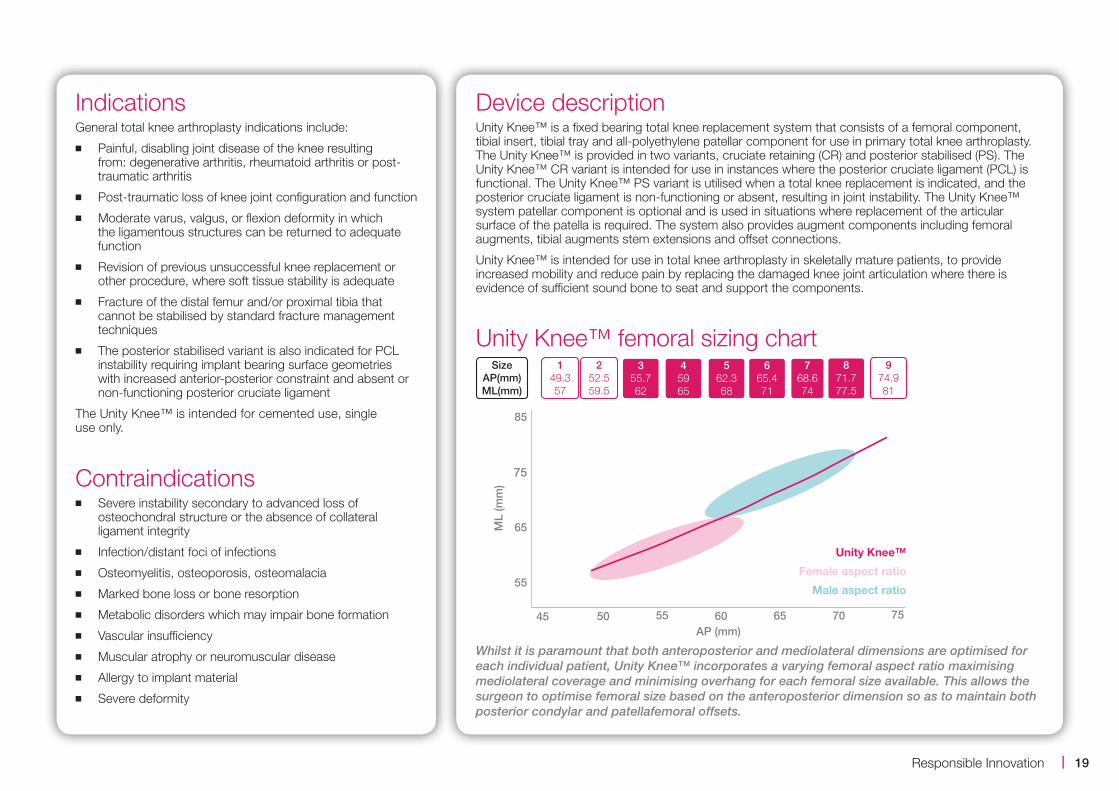
Unity Knee™ femoral sizing chart
Whilst it is paramount that both anteroposterior and mediolateral dimensions are optimised for each individual patient, Unity Knee™ incorporates a varying femoral aspect ratio maximising mediolateral coverage and minimising overhang for each femoral size available. This allows the surgeon to optimise femoral size based on the anteroposterior dimension so as to maintain both posterior condylar and patellafemoral offsets.
45 50 55 60 65 70 75
55
65
75
85
ML
(mm
)
AP (mm)
Unity Knee™
Female aspect ratio
Male aspect ratio
149.357
252.559.5
355.762
45965
562.368
665.471
768.674
871.777.5
974.981
SizeAP(mm)ML(mm)
19 |Responsible Innovation

Ordering informationUnity Knee™ femoral component CR Left112.001.02 Size 1*
112.001.04 Size 2*
112.001.06 Size 3
112.001.08 Size 4
112.001.10 Size 5
112.001.12 Size 6
112.001.14 Size 7
112.001.16 Size 8
112.001.18 Size 9
Unity Knee™ femoral component CR Right112.001.22 Size 1*
112.001.24 Size 2*
112.001.26 Size 3
112.001.28 Size 4
112.001.30 Size 5
112.001.32 Size 6
112.001.34 Size 7
112.001.36 Size 8
112.001.38 Size 9
Unity Knee™ femoral component PS Left112.001.42 Size 1*
112.001.44 Size 2*
112.001.46 Size 3
112.001.48 Size 4
112.001.50 Size 5
112.001.52 Size 6
112.001.54 Size 7
112.001.56 Size 8
112.001.58 Size 9
Unity Knee™ femoral component PS Right112.001.62 Size 1*
112.001.64 Size 2*
112.001.66 Size 3
112.001.68 Size 4
112.001.70 Size 5
112.001.72 Size 6
112.001.74 Size 7
112.001.76 Size 8
112.001.78 Size 9
Tibial component
112.040.02 Size 1*
112.040.04 Size 2*
112.040.06 Size 3
112.040.08 Size 4
112.040.10 Size 5
112.040.12 Size 6
112.040.14 Size 7
112.040.16 Size 8
112.040.18 Size 9
Tibial insert CR size 1*
112.014.02 9mm thickness
112.014.03 10mm thickness
112.014.04 11mm thickness
112.014.05 12mm thickness
112.014.06 14mm thickness
112.014.07 16mm thickness
112.014.08 18mm thickness
112.014.09 20mm thickness
Tibial insert CR size 2*
112.014.22 9mm thickness
112.014.23 10mm thickness
112.014.24 11mm thickness
112.014.25 12mm thickness
112.014.26 14mm thickness
112.014.27 16mm thickness
112.014.28 18mm thickness
112.014.29 20mm thickness
Tibial insert CR size 3
112.014.42 9mm thickness
112.014.43 10mm thickness
112.014.44 11mm thickness
112.014.45 12mm thickness
112.014.46 14mm thickness
112.014.47 16mm thickness
112.014.48 18mm thickness
112.014.49 20mm thickness
Tibial insert CR size 4112.014.62 9mm thickness
112.014.63 10mm thickness
112.014.64 11mm thickness
112.014.65 12mm thickness
112.014.66 14mm thickness
112.014.67 16mm thickness
112.014.68 18mm thickness
112.014.69 20mm thickness
*Not currently available20

Tibial insert CR size 5
112.014.82 9mm thickness
112.014.83 10mm thickness
112.014.84 11mm thickness
112.014.85 12mm thickness
112.014.86 14mm thickness
112.014.87 16mm thickness
112.014.88 18mm thickness
112.014.89 20mm thickness
Tibial insert CR size 6
112.015.02 9mm thickness
112.015.03 10mm thickness
112.015.04 11mm thickness
112.015.05 12mm thickness
112.015.06 14mm thickness
112.015.07 16mm thickness
112.015.08 18mm thickness
112.015.09 20mm thickness
Tibial insert CR size 7
112.015.22 9mm thickness
112.015.23 10mm thickness
112.015.24 11mm thickness
112.015.25 12mm thickness
112.015.26 14mm thickness
112.015.27 16mm thickness
112.015.28 18mm thickness
112.015.29 20mm thickness
Tibial insert CR size 8
112.015.42 9mm thickness
112.015.43 10mm thickness
112.015.44 11mm thickness
112.015.45 12mm thickness
112.015.46 14mm thickness
112.015.47 16mm thickness
112.015.48 18mm thickness
112.015.49 20mm thickness
Tibial insert CR size 9
112.015.62 9mm thickness
112.015.63 10mm thickness
112.015.64 11mm thickness
112.015.65 12mm thickness
112.015.66 14mm thickness
112.015.67 16mm thickness
112.015.68 18mm thickness
112.015.69 20mm thickness
Tibial insert PS size 1
112.016.02 9mm thickness
112.016.03 10mm thickness
112.016.04 11mm thickness
112.016.05 12mm thickness
112.016.06 14mm thickness
112.016.07 16mm thickness
112.016.08 18mm thickness
112.016.09 20mm thickness
Tibial insert PS size 2
112.016.22 9mm thickness
112.016.23 10mm thickness
112.016.24 11mm thickness
112.016.25 12mm thickness
112.016.26 14mm thickness
112.016.27 16mm thickness
112.016.28 18mm thickness
112.016.29 20mm thickness
Tibial insert PS size 3
112.016.42 9mm thickness
112.016.43 10mm thickness
112.016.44 11mm thickness
112.016.45 12mm thickness
112.016.46 14mm thickness
112.016.47 16mm thickness
112.016.48 18mm thickness
112.016.49 20mm thickness
Tibial insert PS size 4
112.016.62 9mm thickness
112.016.63 10mm thickness
112.016.64 11mm thickness
112.016.65 12mm thickness
112.016.66 14mm thickness
112.016.67 16mm thickness
112.016.68 18mm thickness
112.016.69 20mm thickness
21 |Responsible Innovation

Tibial insert PS size 5
112.016.82 9mm thickness
112.016.83 10mm thickness
112.016.84 11mm thickness
112.016.85 12mm thickness
112.016.86 14mm thickness
112.016.87 16mm thickness
112.016.88 18mm thickness
112.016.89 20mm thickness
Tibial insert PS size 6
112.017.02 9mm thickness
112.017.03 10mm thickness
112.017.04 11mm thickness
112.017.05 12mm thickness
112.017.06 14mm thickness
112.017.07 16mm thickness
112.017.08 18mm thickness
112.017.09 20mm thickness
Tibial insert PS size 7
112.017.22 9mm thickness
112.017.23 10mm thickness
112.017.24 11mm thickness
112.017.25 12mm thickness
112.017.26 14mm thickness
112.017.27 16mm thickness
112.017.28 18mm thickness
112.017.29 20mm thickness
Tibial insert PS size 8
112.017.42 9mm thickness
112.017.43 10mm thickness
112.017.44 11mm thickness
112.017.45 12mm thickness
112.017.46 14mm thickness
112.017.47 16mm thickness
112.017.48 18mm thickness
112.017.49 20mm thickness
Tibial insert PS size 9
112.017.62 9mm thickness
112.017.63 10mm thickness
112.017.64 11mm thickness
112.017.65 12mm thickness
112.017.66 14mm thickness
112.017.67 16mm thickness
112.017.68 18mm thickness
112.017.69 20mm thickness
Dome patella
112.018.02 Size 1 7.5mm thickness
112.018.04 Size 2 8.0mm thickness
112.018.06 Size 3 8.5mm thickness
112.018.08 Size 4 9.0mm thickness
112.018.10 Size 5 9.5mm thickness
Offset dome patella
112.018.42 Size 1 8.0mm thickness
112.018.46 Size 2 8.5mm thickness
112.018.52 Size 3 9.0mm thickness
112.018.56 Size 4 9.5mm thickness
22

PS thickness (mm)
910111214161820
Size 1 Size 2 Size 3 Size 4 Size 5 Size 6 Size 7 Size 8 Size 9
Size 2 Size 3 Size 4 Size 5 Size 6 Size 7 Size 8 Size 9Size 1
910111214161820
CR thickness (mm)
or or or or or or or or or
or or or or or or or or or
Micro size range Macro size rangeStandard size range
Sizing guide
5
n/a
9.5mm
4
9.5mm
9.0mm
3
9.0mm
8.5mm
2
8.5mm
8.0mm
1
8.0mm
7.5mm
Size
Offset dome patella
Centred dome patella
Patella options
23 |Responsible Innovation

The Corinium CentreCirencester, GL7 1YJ, UKt: +44 (0)1285 659 866f: +44 (0)1285 658 960e: [email protected]
©2016 Corin P No I1136 Rev6 09/2016 ECR 650