Embed Size (px)
Citation preview
Unity 550VERSION 1
Enterprise Media Receiver
Unity 550VERSION 1
Enterprise Media ReceiverUser’s Manual
800072-01 Rev. A
Unity 550 User’s Manual
ii 800072-01 Rev. A www.wegener.com
A proven world leader in digital video, audio & broadcast data systems, WEGENER's management system is certified to ISO 9001:2000.
Data, drawings, and other material contained herein are proprietary to Wegener Communications, Inc., and may not be reproduced or duplicated in any form without the prior written permission of Wegener Communications, Inc.
The information contained herein is subject to change without notice. Revisions may be issued to advise of such changes and/or additions.
WEGENER®, COMPEL CONTROL®, MEDIAPLAN®, ENVOY, UNITY®, UNITY·IP®, and iPUMP® are trademarks of Wegener Communications, Inc. All other trademarks are the property of their respective owners.
© 2006 Wegener Communications, Inc. All rights reserved.
Correspondence regarding this publication,
800072-01 Rev. A First Edition: September 2006
should be forwarded to:
Wegener Communications, Inc. Technology Park/Johns Creek 11350 Technology Circle Duluth, GA 30097-1502
Phone: 770-814-4000 Fax: 770-623-0698
The Wegener Unity 550 is approved under FCC Part 15B Class A, UL/C-UL1950 3rd Edition, and CE [EN60950, EN55022(94), and EN55024(98)].
www.wegener.com 800072-01 Rev. A 1
Unity 550 User’s Manual
TABLE OF CONTENTS
CHAPTER 1 GENERAL INFORMATION
1.1 Manual Overview . . . . . . . . . . . . . . . . . . . . . . . . . . . . . . . . . . . . . . . . . . . . . 31.2 Unity 550 Product Overview. . . . . . . . . . . . . . . . . . . . . . . . . . . . . . . . . . . . 3
Digital Television Receiver . . . . . . . . . . . . . . . . . . . . . . . . . . . . . . . . . . . . . . . . . . . 3Unity 550 Features and Options . . . . . . . . . . . . . . . . . . . . . . . . . . . . . . . . . . . . . . . 4COMPEL™ Network Control . . . . . . . . . . . . . . . . . . . . . . . . . . . . . . . . . . . . . . . . . . 4
1.3 Unity 550 Product Specifications . . . . . . . . . . . . . . . . . . . . . . . . . . . . . . . 41.4 Safety Summary . . . . . . . . . . . . . . . . . . . . . . . . . . . . . . . . . . . . . . . . . . . . . 6
CHAPTER 2 INSTALLATION
2.1 Unpacking and Inspection . . . . . . . . . . . . . . . . . . . . . . . . . . . . . . . . . . . . . 92.2 Location and Mounting. . . . . . . . . . . . . . . . . . . . . . . . . . . . . . . . . . . . . . . . 9
Precautions . . . . . . . . . . . . . . . . . . . . . . . . . . . . . . . . . . . . . . . . . . . . . . . . . . . . . . . 9FCC-Mandated Suppression of Radio Frequency Emissions. . . . . . . . . . . . . . 9Elevated Ambient Operating Temperatures in Rack-Mounted Units . . . . . . . . 9Reduced Air Flow . . . . . . . . . . . . . . . . . . . . . . . . . . . . . . . . . . . . . . . . . . . . . . . 9Mechanical Loading . . . . . . . . . . . . . . . . . . . . . . . . . . . . . . . . . . . . . . . . . . . . . 9Circuit Overloading . . . . . . . . . . . . . . . . . . . . . . . . . . . . . . . . . . . . . . . . . . . . . 10Reliable Earthing. . . . . . . . . . . . . . . . . . . . . . . . . . . . . . . . . . . . . . . . . . . . . . . 10Rack Mounting . . . . . . . . . . . . . . . . . . . . . . . . . . . . . . . . . . . . . . . . . . . . . . . . 10Desktop Installation. . . . . . . . . . . . . . . . . . . . . . . . . . . . . . . . . . . . . . . . . . . . . 10
2.3 Rear Panel Connections . . . . . . . . . . . . . . . . . . . . . . . . . . . . . . . . . . . . . . 11Connection Descriptions . . . . . . . . . . . . . . . . . . . . . . . . . . . . . . . . . . . . . . . . . . . . 11
CHAPTER 3 OPERATION
3.1 Front Panel Controls And Indicators. . . . . . . . . . . . . . . . . . . . . . . . . . . . 13LCD Menu Navigation . . . . . . . . . . . . . . . . . . . . . . . . . . . . . . . . . . . . . . . . . . . . . . 13Front Panel Functions . . . . . . . . . . . . . . . . . . . . . . . . . . . . . . . . . . . . . . . . . . . . . . 14
Programming Setup . . . . . . . . . . . . . . . . . . . . . . . . . . . . . . . . . . . . . . . . . . . . 14Audio Setup . . . . . . . . . . . . . . . . . . . . . . . . . . . . . . . . . . . . . . . . . . . . . . . . . . 14Sub-titling Setup . . . . . . . . . . . . . . . . . . . . . . . . . . . . . . . . . . . . . . . . . . . . . . . 14
3.2 LED Status and Alarm/Warning Conditions . . . . . . . . . . . . . . . . . . . . . . 14LED definitions . . . . . . . . . . . . . . . . . . . . . . . . . . . . . . . . . . . . . . . . . . . . . . . . . . . 14LED behavior. . . . . . . . . . . . . . . . . . . . . . . . . . . . . . . . . . . . . . . . . . . . . . . . . . . . . 15
3.3 Power-On Procedure. . . . . . . . . . . . . . . . . . . . . . . . . . . . . . . . . . . . . . . . . 153.4 On-Screen Network E-mail . . . . . . . . . . . . . . . . . . . . . . . . . . . . . . . . . . . . 163.5 IP Repeater Mode . . . . . . . . . . . . . . . . . . . . . . . . . . . . . . . . . . . . . . . . . . . 163.6 On-Screen Display (OSD) . . . . . . . . . . . . . . . . . . . . . . . . . . . . . . . . . . . . . 17
OSD Setup . . . . . . . . . . . . . . . . . . . . . . . . . . . . . . . . . . . . . . . . . . . . . . . . . . . . . . 17
2 800072-01 Rev. A www.wegener.com
OSD Menus . . . . . . . . . . . . . . . . . . . . . . . . . . . . . . . . . . . . . . . . . . . . . . . . . . . . . . 17Navigating OSD Menus . . . . . . . . . . . . . . . . . . . . . . . . . . . . . . . . . . . . . . . . . . . . . 17
3.7 Customizing and Viewing Settings for Your System. . . . . . . . . . . . . . . 18COMPEL™ System Control. . . . . . . . . . . . . . . . . . . . . . . . . . . . . . . . . . . . . . . . . . 18OSD (On-Screen Display) Settings . . . . . . . . . . . . . . . . . . . . . . . . . . . . . . . . . . . . 18Carrier Status. . . . . . . . . . . . . . . . . . . . . . . . . . . . . . . . . . . . . . . . . . . . . . . . . . . . . 19Carrier Select . . . . . . . . . . . . . . . . . . . . . . . . . . . . . . . . . . . . . . . . . . . . . . . . . . . . . 19Signal Strength . . . . . . . . . . . . . . . . . . . . . . . . . . . . . . . . . . . . . . . . . . . . . . . . . . . 20Serial Port Select . . . . . . . . . . . . . . . . . . . . . . . . . . . . . . . . . . . . . . . . . . . . . . . . . . 20Audio Settings . . . . . . . . . . . . . . . . . . . . . . . . . . . . . . . . . . . . . . . . . . . . . . . . . . . . 21Software Versions . . . . . . . . . . . . . . . . . . . . . . . . . . . . . . . . . . . . . . . . . . . . . . . . . 22Data PIDS Settings . . . . . . . . . . . . . . . . . . . . . . . . . . . . . . . . . . . . . . . . . . . . . . . . 22
3.8 Universal European Single User LNB . . . . . . . . . . . . . . . . . . . . . . . . . . . 23
CHAPTER 4 SEARCH FUNCTIONS
4.1 Perms/Temps/Searching & Settings . . . . . . . . . . . . . . . . . . . . . . . . . . . . 254.2 Settings Table (or Search Table) . . . . . . . . . . . . . . . . . . . . . . . . . . . . . . . 264.3 Acquisition Modes . . . . . . . . . . . . . . . . . . . . . . . . . . . . . . . . . . . . . . . . . . 264.4 Acquisition Sub-Modes . . . . . . . . . . . . . . . . . . . . . . . . . . . . . . . . . . . . . . 284.5 Signal Quality Monitoring. . . . . . . . . . . . . . . . . . . . . . . . . . . . . . . . . . . . . 294.6 Frequency Tagging . . . . . . . . . . . . . . . . . . . . . . . . . . . . . . . . . . . . . . . . . . 30
General Rules . . . . . . . . . . . . . . . . . . . . . . . . . . . . . . . . . . . . . . . . . . . . . . . . . . . . 30
CHAPTER 5 CUSTOMER SERVICE
5.1 Warranty. . . . . . . . . . . . . . . . . . . . . . . . . . . . . . . . . . . . . . . . . . . . . . . . . . . 315.2 Technical Support . . . . . . . . . . . . . . . . . . . . . . . . . . . . . . . . . . . . . . . . . . . 31
APPENDIX A: TERMINAL/MODEM MODETerminal/Modem Commands .......................................................................... 33
Network-Enabled Local Control Commands . . . . . . . . . . . . . . . . . . . . . . . . . . . . . 33Local Control Commands . . . . . . . . . . . . . . . . . . . . . . . . . . . . . . . . . . . . . . . . . . . 35
Reports .............................................................................................................. 37Carrier Status (Tracking) . . . . . . . . . . . . . . . . . . . . . . . . . . . . . . . . . . . . . . . . . . . . 37Carrier Status (Not Tracking) . . . . . . . . . . . . . . . . . . . . . . . . . . . . . . . . . . . . . . . . . 39Parameters . . . . . . . . . . . . . . . . . . . . . . . . . . . . . . . . . . . . . . . . . . . . . . . . . . . . . . 40Group Status . . . . . . . . . . . . . . . . . . . . . . . . . . . . . . . . . . . . . . . . . . . . . . . . . . . . . 42Network Controller Status . . . . . . . . . . . . . . . . . . . . . . . . . . . . . . . . . . . . . . . . . . . 43MPEG Status . . . . . . . . . . . . . . . . . . . . . . . . . . . . . . . . . . . . . . . . . . . . . . . . . . . . . 44Settings Status. . . . . . . . . . . . . . . . . . . . . . . . . . . . . . . . . . . . . . . . . . . . . . . . . . . . 45Settings Table . . . . . . . . . . . . . . . . . . . . . . . . . . . . . . . . . . . . . . . . . . . . . . . . . . . . 46
APPENDIX B: RMA REQUEST FORMReturn Materials Authorization Request Form .............................................. 49
www.wegener.com 800072-01 Rev. A 1
Unity 550 User’s Manual
LIST OF TABLES
Table 1.1: Unity 550 Technical Specifications ............................................................4
Table 2.1: Unity 550 Interconnect Descriptions .......................................................11
Table 2.2: Unity 550 Serial Cables to Terminal or Printer .........................................11
Table 3.1: Unity 550 Front Panel Controls and Indicators .......................................13
Table 3.2: Unity 550 Status LED Indications ............................................................15
Table 3.3: Unity 550 Types of OSD Action Fields .....................................................18
Table 4.1: Settings Parameters for the Unity 550 .....................................................25
Table 4.2: Unity 550 Settings Groups .......................................................................26
Table 4.3: Acquisition Mode Behavior ......................................................................28
Table 4.4: Signal Quality Information ........................................................................30
Table A.1: Unity 550 Network-Enabled Local Control Commands ............................33
Table A.2: Unity 550 Local Control Commands ........................................................36
Table A.3: Terms Used in Unity 550 Carrier Status (Tracking) Reports ...................38
Table A.4: Terms Used in Unity 550 Carrier Status (Not Tracking) Reports .............39
Table A.5: Terms Used in Unity 550 Parameters Reports ........................................41
Table A.6: Terms Used in U550 Group Status Reports ............................................42
Table A.7: Terms Used in Unity 550 Network Control Status Reports ......................43
Table A.8: Terms Used in Unity 550 MPEG Status Reports .....................................45
Table A.9: Terms Used in Unity 550 Settings Status Reports ..................................46
Table A.10: Terms Used in Unity 550 Settings Table Reports ....................................48

Unity 550 User’s Manual
2 800072-01 Rev. A www.wegener.com
www.wegener.com 800072-01 Rev. A 1
Unity 550 User’s Manual
LIST OF FIGURES
Figure 2.1: Unity 550 Rear Panel ...............................................................................11
Figure 3.1: Unity 550 Front Panel ..............................................................................13
Figure 3.2: Unity 550 OSD Welcome Banner Screen ................................................16
Figure 3.3: Unity 550 OSD Main Menu ......................................................................17
Figure 3.4: Unity 550 OSD Carrier Status Screen .....................................................19
Figure 3.5: Unity 550 OSD Carrier Select Screen ......................................................20
Figure 3.6: Unity 550 OSD Signal Strength Screen ...................................................20
Figure 3.7: Unity 550 OSD Serial Port Select Screen ................................................21
Figure 3.8: Unity 550 OSD Audio Settings Screen ....................................................22
Figure 3.9: Unity 550 OSD Software Version/Serial No. Screen ...............................22
Figure 3.10: Unity 550 Data PIDS Settings Screen .....................................................23
Figure 4.1: Acquisition Modes ....................................................................................27
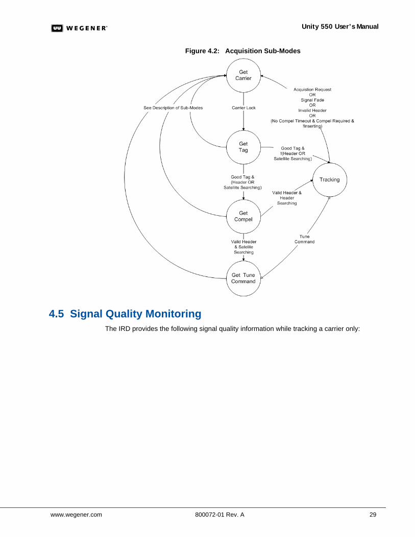
Figure 4.2: Acquisition Sub-Modes ............................................................................29
Figure A.1: Sample Unity 550 Carrier Status (Tracking) Report ................................37
Figure A.2: Sample Unity 550 Carrier Status (Not Tracking) Report ..........................39
Figure A.3: Sample Unity 550 Parameters Report .....................................................40
Figure A.4: Sample Unity 550 Group Status Report ...................................................42
Figure A.5: Sample Unity 550 Parameters Report .....................................................43
Figure A.6: Sample Unity 550 MPEG Status Report ..................................................44
Figure A.7: Sample Unity 550 Settings Status Report ...............................................45
Figure A.8: Sample Unity 550 Settings Table Report (Without Labels) .....................46
Figure A.9: Sample Unity 550 Settings Table Report (With Labels) ..........................48
Figure B.1: RMA Request Form .................................................................................49

Unity 550 User’s Manual
2 800072-01 Rev. A www.wegener.com
www.wegener.com 800072-01 Rev. A 3
Unity 550 User’s Manual
CHAPTER 1 GENERAL INFORMATION
1.1 Manual OverviewThis manual provides instructions and reference information for the proper installation and operation of the Wegener Unity 550.
The manual is divided into the following chapters:
1. General Information - A description of the Unity 550, its functions and specifications, and a glossary of terms
2. Installation - Procedures and information for the correct and safe installation of the Unity 550
3. Operation - Instructions on starting and operating the Unity 550
4. Search Functions - Information on settings, pararmeters, modes, and signal monitoring for the Unity 550.
5. Customer Service - Our warranty and information about obtaining help.
An Index of keywords is also provided to help you quickly locate needed information.
Please E-mail any suggestions or comments concerning this manual to [email protected]. If you prefer to post through the mail, please send your comments to the address below. If you have substantial or complex changes to recommend, our preference is that you copy the page(s) in question, mark your changes on that copy, and fax or mail us the copy. We always appreciate constructive criticism.
Address:
Fax number: (770) 497-0411
1.2 Unity 550 Product OverviewDigital Television Receiver
The Unity 550 Digital Television Receiver is a high-performance satellite Integrated Receiver-Decoder (IRD) designed to meet the needs of the private television market-place. Supporting both the PAL and NTSC video standards, the Unity 550 is uniquely positioned to provide high-quality video, audio, and data to demanding customers. The Unity 550 supports DVB World Standard Teletext and Line 21 Closed Captioning and Extended Data for enhanced video functionality.
Multiple data features are standard to provide additional ways to use spare digital spectrum for revenue and operational control. A 38.4-kbps asynchronous output provides constant streaming of control and user information. This data port is used for local and remote diagnostics, COMPEL™ data delivery services, and auxiliary data. Using COMPEL, the data output can control external devices, such as collection encoding systems and video switching equipment. COMPEL is able to command the serial number to be displayed on screen for asset protection.
Attn: Manuals
Wegener Communications, Inc.Technology Park / Johns Creek 11350 Technology Circle Duluth, GA 30097-1502
Chapter 1: General Information
4 800072-01 Rev. A www.wegener.com
Unity 550 Features and Options
The Unity 550 utilizes and supports the following standards:
MPEG-2/DVB Compliant 2.5 - 30 Msps Symbol Rate SCPC and MCPC RS-232 Asynch Data up to 384 Kbps Line 21 Closed Captioning and Extended Data World Standard Teletext On-Screen Control
The Unity 550 has integral support for the following COMPEL™ features:
COMPEL™ Network Control COMPEL™ CA and Wegener PIN Scrambling COMPEL™ On-Screen E-Mail
COMPEL™ Network Control
COMPEL gives you the power to manage a network of Unity 550s and other Unity IRDs with unparalleled functionality. With its unique network management features, such as grouping, receiver control and scheduling, the operator can command individual groups of receivers to switch, tune, or "output" video or data targeted specifically for that one receiver or group of receivers. In addition, COMPEL is able to switch the Unity 550 between satellite transponders - even to a different satellite - for unequalled disaster recovery.
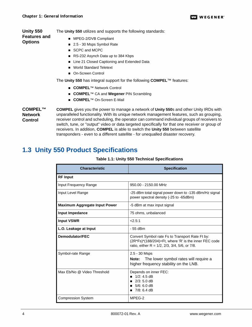
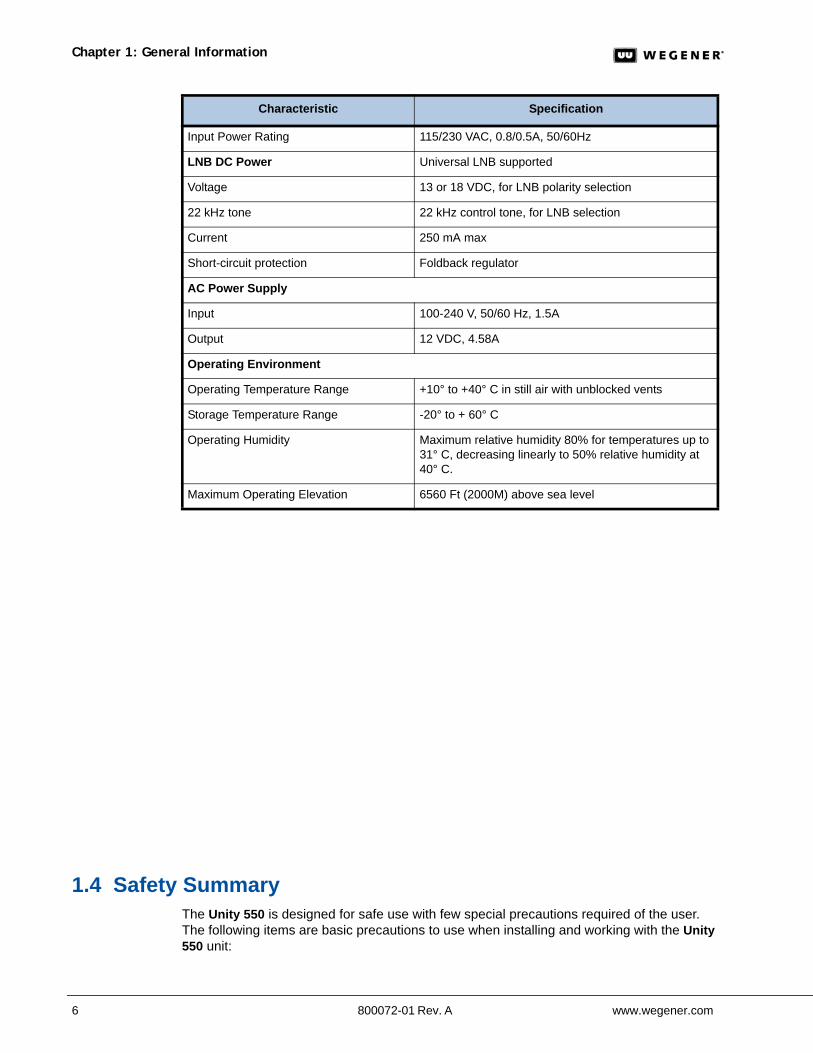
1.3 Unity 550 Product SpecificationsTable 1.1: Unity 550 Technical Specifications
Characteristic Specification
RF Input
Input Frequency Range 950.00 - 2150.00 MHz
Input Level Range -25 dBm total signal power down to -135 dBm/Hz signal power spectral density (-25 to -65dBm)
Maximum Aggregate Input Power -5 dBm at max input signal
Input Impedance 75 ohms, unbalanced
Input VSWR <2.5:1
L.O. Leakage at Input - 55 dBm
Demodulator/FEC Convert Symbol rate Fs to Transport Rate Ft by: (2R*Fs)*(188/204)=Ft, where 'R' is the inner FEC code ratio, either R = 1/2, 2/3, 3/4, 5/6, or 7/8.
Symbol-rate Range 2.5 - 30 Msps Note: The lower symbol rates will require a higher frequency stability on the LNB.
Max Eb/No @ Video Threshold Depends on inner FEC: 1/2: 4.5 dB 2/3: 5.0 dB 5/6: 6.0 dB 7/8: 6.4 dB
Compression System MPEG-2
www.wegener.com 800072-01 Rev. A 5
Unity 550 User’s Manual
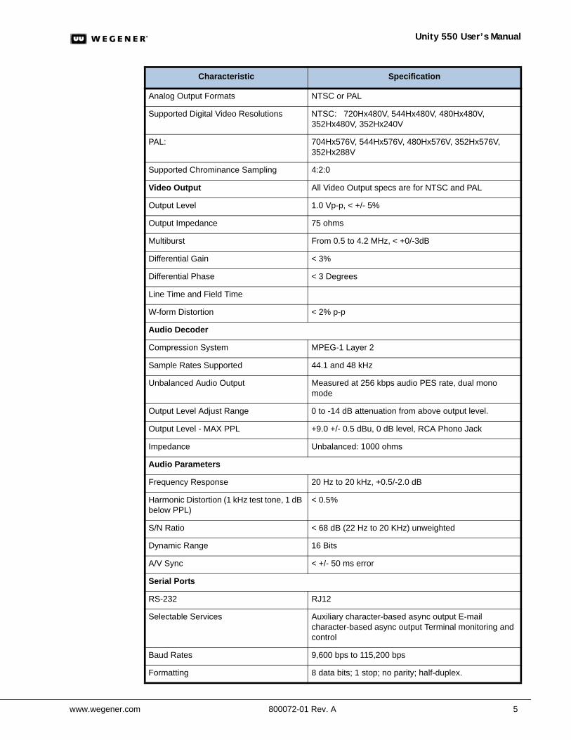
Analog Output Formats NTSC or PAL
Supported Digital Video Resolutions NTSC: 720Hx480V, 544Hx480V, 480Hx480V, 352Hx480V, 352Hx240V
PAL: 704Hx576V, 544Hx576V, 480Hx576V, 352Hx576V, 352Hx288V
Supported Chrominance Sampling 4:2:0
Video Output All Video Output specs are for NTSC and PAL
Output Level 1.0 Vp-p, < +/- 5%
Output Impedance 75 ohms
Multiburst From 0.5 to 4.2 MHz, < +0/-3dB
Differential Gain < 3%
Differential Phase < 3 Degrees
Line Time and Field Time
W-form Distortion < 2% p-p
Audio Decoder
Compression System MPEG-1 Layer 2
Sample Rates Supported 44.1 and 48 kHz
Unbalanced Audio Output Measured at 256 kbps audio PES rate, dual mono mode
Output Level Adjust Range 0 to -14 dB attenuation from above output level.
Output Level - MAX PPL +9.0 +/- 0.5 dBu, 0 dB level, RCA Phono Jack
Impedance Unbalanced: 1000 ohms
Audio Parameters
Frequency Response 20 Hz to 20 kHz, +0.5/-2.0 dB
Harmonic Distortion (1 kHz test tone, 1 dB below PPL)
< 0.5%
S/N Ratio < 68 dB (22 Hz to 20 KHz) unweighted
Dynamic Range 16 Bits
A/V Sync < +/- 50 ms error
Serial Ports
RS-232 RJ12
Selectable Services Auxiliary character-based async output E-mail character-based async output Terminal monitoring and control
Baud Rates 9,600 bps to 115,200 bps
Formatting 8 data bits; 1 stop; no parity; half-duplex.
Characteristic Specification
Chapter 1: General Information
6 800072-01 Rev. A www.wegener.com
1.4 Safety SummaryThe Unity 550 is designed for safe use with few special precautions required of the user. The following items are basic precautions to use when installing and working with the Unity 550 unit:
Input Power Rating 115/230 VAC, 0.8/0.5A, 50/60Hz
LNB DC Power Universal LNB supported
Voltage 13 or 18 VDC, for LNB polarity selection
22 kHz tone 22 kHz control tone, for LNB selection
Current 250 mA max
Short-circuit protection Foldback regulator
AC Power Supply
Input 100-240 V, 50/60 Hz, 1.5A
Output 12 VDC, 4.58A
Operating Environment
Operating Temperature Range +10° to +40° C in still air with unblocked vents
Storage Temperature Range -20° to + 60° C
Operating Humidity Maximum relative humidity 80% for temperatures up to 31° C, decreasing linearly to 50% relative humidity at 40° C.
Maximum Operating Elevation 6560 Ft (2000M) above sea level
Characteristic Specification
www.wegener.com 800072-01 Rev. A 7
Unity 550 User’s Manual
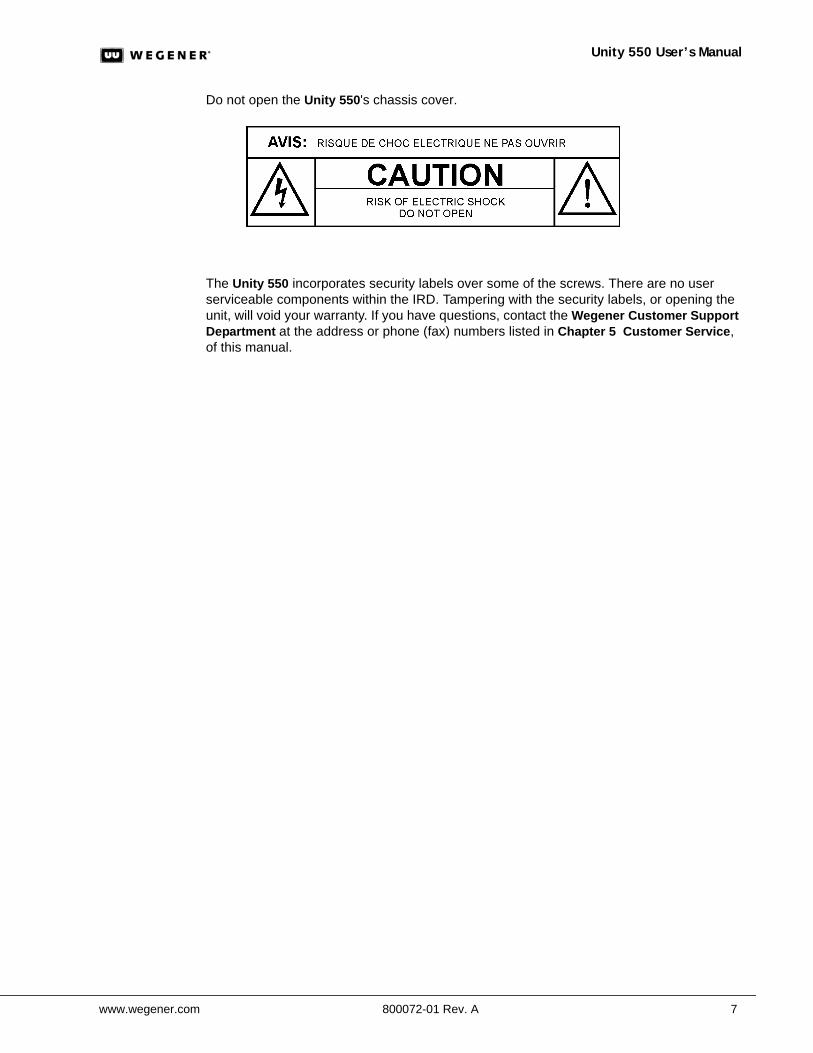
Do not open the Unity 550's chassis cover.
The Unity 550 incorporates security labels over some of the screws. There are no user serviceable components within the IRD. Tampering with the security labels, or opening the unit, will void your warranty. If you have questions, contact the Wegener Customer Support Department at the address or phone (fax) numbers listed in Chapter 5 Customer Service, of this manual.

Chapter 1: General Information
8 800072-01 Rev. A www.wegener.com
www.wegener.com 800072-01 Rev. A 9
Unity 550 User’s Manual
CHAPTER 2 INSTALLATION
This chapter provides instructions on unpacking, mounting, and connecting your Unity 550 as well as connector information including detailed pinouts.
2.1 Unpacking and InspectionCarefully unpack the unit and its ac power cord and inspect for obvious signs of physical damage that might have occurred during shipment. Any damage claims must be reported to the carrier immediately. Be sure to check the package contents carefully for important documents and materials.
Note: Please save the packing materials and original shipping containers in case you must later return the unit for repair. Packing these units in other containers in such a way that they are damaged will void your warranty.
2.2 Location and MountingThe Unity 550 may be mounted in a standard 19-inch equipment rack or set up for desktop operation. In either location, maintain a clean, dry environment for the Unity 550.
Precautions FCC-Mandated Suppression of Radio Frequency Emissions
WARNING This is a Class A product. In a domestic environment this product may cause radio interference for which the user may need to take mitigating action.
If the Ethernet port has a cable connected to it, that cable must be properly shielded and grounded to minimize RF emissions that could interfere with nearby equipment.
DANGER To avoid damage to the Unity 550 unit and other equipment, or personal injury, the following items should be strictly observed.
Elevated Ambient Operating Temperatures in Rack-Mounted Units
When equipment is installed in a closed or multi-unit rack assembly, the ambient operating temperature of the rack environment may be greater than the room's ambient temperature. Therefore, consideration should be given to the ambient air temperature within the rack (not just inside the room) when deciding if the maximum recommended ambient operating temperature (TMRA) is met or exceeded.
Reduced Air Flow
Equipment should be installed such that the airflow required for safe operation of the equipment is not compromised. The Unity 550 may be arranged in a rack without empty spaces between units, if heat buildup is prevented by ensuring that the side vents remain unblocked, and that there is adequate clearance around the vent holes.
Mechanical Loading
Rack-mounted equipment should be installed in such a way that a hazardous condition is not produced by uneven loading. The Unity 550 unit is not very heavy, but total rack loading must be considered. Also, do not rest any unsupported equipment on a rack-mounted Unity 550 unit.
Chapter 2: Installation
10 800072-01 Rev. A www.wegener.com
Circuit Overloading
Consideration should be given to the connection of the equipment to the supply circuit and the effect that overloading of circuits could have on overcurrent protection and supply wiring. Ensure that the total rack or breaker power consumption does not exceed the limits of the AC branch circuit. Appropriate consideration of equipment ratings should be used when addressing this concern.
Reliable Earthing
When connecting the Unity 550 unit to the power supply, review the ratings of all equipment in the circuit to ensure that the branch circuit, as well as the power source, will not be overloaded. Also make sure that the unit is properly grounded and/or that a protected power strip is used to attach it to the power supply
Rack Mounting
The Unity 550 unit should be installed in such a way that a half-inch clearance is allowed on each side and a quarter-inch on the top to ensure adequate air flow. Ensure that a hazardous condition is not produced by uneven loading, or by resting any unsupported equipment on a rack-mounted Unity 550 unit.
Parts for the Unity 550 unit include 2 angle rack mount brackets and 4 rubber feet. For rack mounting, do not attach the rubber feet as they interfere with the rack mounting.
1. Remove the 2 screws from the left and right sides of the unit.
2. Insert the angle brackets into the left and right sides of the unit ensuring that the screw holes for the unit and brackets are aligned.
3. Secure the brackets by re-inserting the screws through the brackets and unit.
4. Install the unit onto the rack.
Note: The front brackets must be secured to the rack. If the front brackets are left unsecured, the unit may shift forward and fall from the rack, and may result in personal injury and/or damage to the equipment. The internal temperature of the rack should not exceed 40o C.
Desktop Installation
Parts for the Unity 550 unit include 2 angle rack mount brackets and 4 rubber feet. For desktop installation, do not attach the brackets.
1. Attach the 4 rubber feet onto the indented areas at the bottom of the unit.
2. Place the unit on a flat surface where it will not be subject to spills or impacts.
3. Route cables to the unit so that they will not be hit or pulled, causing damage to the connectors or to the unit itself. Ensure a sufficient flow of cool air so that the unit's operating ambient temperature range is not exceeded.
www.wegener.com 800072-01 Rev. A 11
Unity 550 User’s Manual
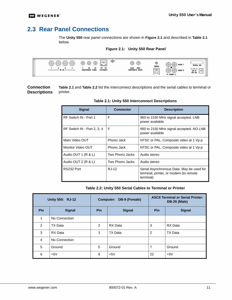
2.3 Rear Panel ConnectionsThe Unity 550 rear panel connections are shown in Figure 2.1 and described in Table 2.1 below.
Figure 2.1: Unity 550 Rear Panel
Connection Descriptions
Table 2.1 and Table 2.2 list the interconnect descriptions and the serial cables to terminal or printer.
Table 2.1: Unity 550 Interconnect Descriptions
Table 2.2: Unity 550 Serial Cables to Terminal or Printer
Signal Connector Description
RF Switch IN - Port 1 F 950 to 2150 MHz signal accepted. LNB power available
RF Switch IN - Port 2, 3, 4 F 950 to 2150 MHz signal accepted. NO LNB power available
Main Video OUT Phono Jack NTSC or PAL, Composite video at 1 Vp-p
Monitor Video OUT Phono Jack NTSC or PAL, Composite video at 1 Vp-p
Audio OUT 1 (R & L) Two Phono Jacks Audio stereo
Audio OUT 2 (R & L) Two Phono Jacks Audio stereo
RS232 Port RJ-12 Serial Asynchronous Data. May be used for terminal, printer, or modem (to remote terminal)
Unity 550: RJ-12 Computer: DB-9 (Female) ASCII Terminal or Serial Printer: DB-25 (Male)
Pin Signal Pin Signal Pin Signal
1 No Connection
2 TX Data 2 RX Data 3 RX Data
3 RX Data 3 TX Data 2 TX Data
4 No Connection
5 Ground 5 Ground 7 Ground
6 +5V 9 +5V 22 +5V

Chapter 2: Installation
12 800072-01 Rev. A www.wegener.com
www.wegener.com 800072-01 Rev. A 13
Unity 550 User’s Manual
CHAPTER 3 OPERATION
This chapter provides information and procedures for powering up and operating the unit.
The IRD can be controlled via COMPEL, local terminal, modem (remote terminal), and OSD (On-Screen-Display) push buttons. Normally, COMPEL is the primary method of controlling the IRD, while the other control methods are supplemental. See COMPEL™ System Control on page 18 for more information, and the COMPEL Manual for a complete explanation of COMPEL controls.
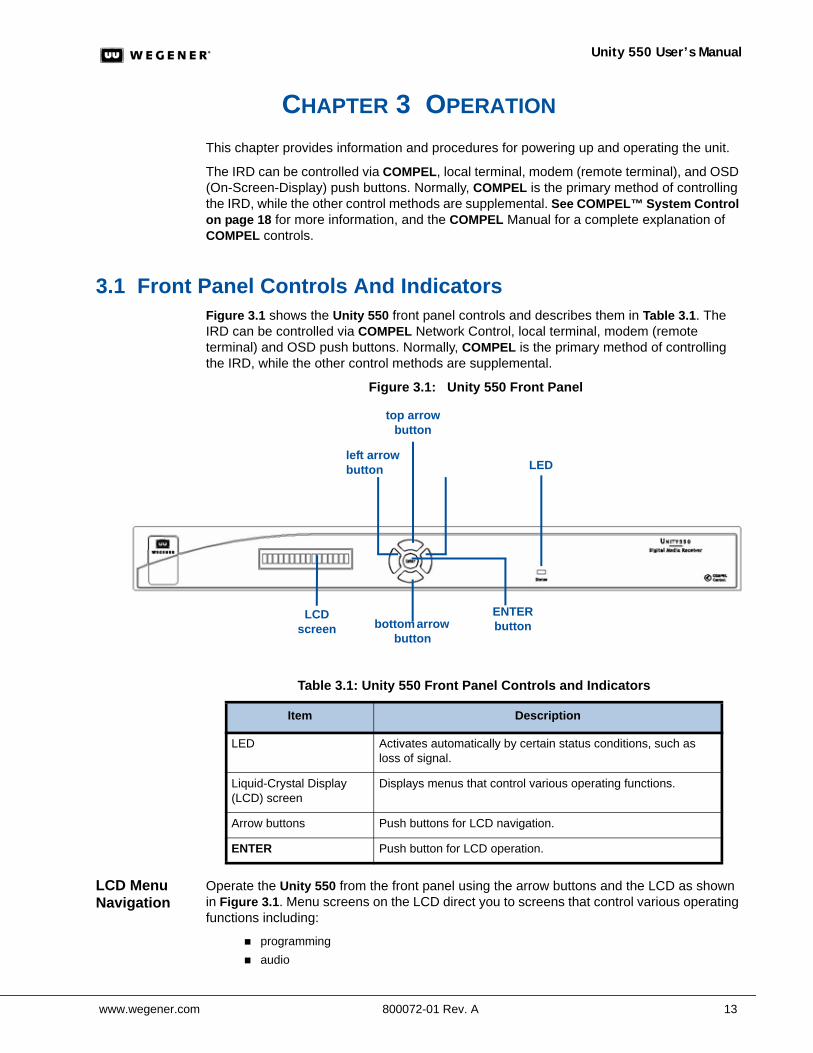
3.1 Front Panel Controls And IndicatorsFigure 3.1 shows the Unity 550 front panel controls and describes them in Table 3.1. The IRD can be controlled via COMPEL Network Control, local terminal, modem (remote terminal) and OSD push buttons. Normally, COMPEL is the primary method of controlling the IRD, while the other control methods are supplemental.
Figure 3.1: Unity 550 Front Panel
Table 3.1: Unity 550 Front Panel Controls and Indicators
LCD Menu Navigation
Operate the Unity 550 from the front panel using the arrow buttons and the LCD as shown in Figure 3.1. Menu screens on the LCD direct you to screens that control various operating functions including:
programming audio
LCD screen bottom arrow
button
ENTER button
left arrow button
top arrow button
LED
Item Description
LED Activates automatically by certain status conditions, such as loss of signal.
Liquid-Crystal Display (LCD) screen
Displays menus that control various operating functions.
Arrow buttons Push buttons for LCD navigation.
ENTER Push button for LCD operation.
Chapter 3: Operation
14 800072-01 Rev. A www.wegener.com
Front Panel Functions
Programming Setup
1. Use the right or left arrow buttons to navigate to Prgm:Prog N.
Note: N represents the available program.
2. To edit, press ENTER.The program begins flashing.
3. Use the up or down arrows to cycle through any available programs
4. To select a program, press ENTER.
Audio Setup
1. Use to setup Audio 1 or Audio 2 as indicated on the rear of the unit chassis.
2. Use the right or left arrow buttons to navigate to Aud1:NNN
Note: NNN represents the available program. An asterisk preceeding the program (Aud1: *NNN) indicates that it is the first available program.
3. To edit, press ENTER. The program number begins flashing.
4. Use the up or down arrows to cycle through any available programs.
5. To select a program, press ENTER.
Sub-titling Setup
This feature is not available for edit in the initial release.
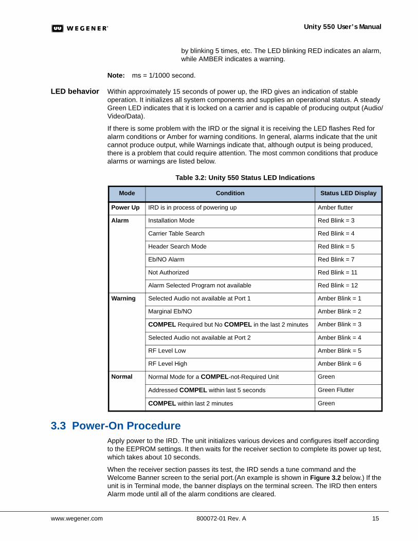
3.2 LED Status and Alarm/Warning ConditionsThe Unity 550 unit's only LED is Red/Green, located on the front panel, and labeled Status. Table 3.2, lists the behavior of the Status LED during Power Up and Normal operation, as well as the color and blink/flutter pattern shown during various Warning and Alarm conditions.
The conditions are listed in the order of their display priority with highest priority at the top.
Note: The alarm conditions are those conditions preventing the delivery of video.
LED definitions
The following definitions of Amber, Flash, Blink, and Flutter explain the terms used in the Status LED Display column of Table 3.2 on page 15.
Amber Red and Green turned ON at the same time.
Flash ON for 100 ms, OFF for 100 ms.
Flutter ON for 50 ms, OFF for 50 ms.
Blink LED is OFF for 1 second, then blinks ON for 250 ms and OFF for 250 ms between 1 and 12 times, according to the Alarm/Warning Code. Is then OFF for 1 second, and blinks 1-12 times again. This pattern continues until the alarm/warning condition is cleared. (For example, if the unit is displaying a "header search mode" alarm, the LED will be OFF for 1 sec., then will blink (RED) ON for 250 ms and OFF for 250 ms five times. It will then be OFF for 1 sec., followed
www.wegener.com 800072-01 Rev. A 15
Unity 550 User’s Manual
by blinking 5 times, etc. The LED blinking RED indicates an alarm, while AMBER indicates a warning.
Note: ms = 1/1000 second.
LED behavior Within approximately 15 seconds of power up, the IRD gives an indication of stable operation. It initializes all system components and supplies an operational status. A steady Green LED indicates that it is locked on a carrier and is capable of producing output (Audio/Video/Data).
If there is some problem with the IRD or the signal it is receiving the LED flashes Red for alarm conditions or Amber for warning conditions. In general, alarms indicate that the unit cannot produce output, while Warnings indicate that, although output is being produced, there is a problem that could require attention. The most common conditions that produce alarms or warnings are listed below.
Table 3.2: Unity 550 Status LED Indications
3.3 Power-On ProcedureApply power to the IRD. The unit initializes various devices and configures itself according to the EEPROM settings. It then waits for the receiver section to complete its power up test, which takes about 10 seconds.
When the receiver section passes its test, the IRD sends a tune command and the Welcome Banner screen to the serial port.(An example is shown in Figure 3.2 below.) If the unit is in Terminal mode, the banner displays on the terminal screen. The IRD then enters Alarm mode until all of the alarm conditions are cleared.
Mode Condition Status LED Display
Power Up IRD is in process of powering up Amber flutter
Alarm Installation Mode Red Blink = 3
Carrier Table Search Red Blink = 4
Header Search Mode Red Blink = 5
Eb/NO Alarm Red Blink = 7
Not Authorized Red Blink = 11
Alarm Selected Program not available Red Blink = 12
Warning Selected Audio not available at Port 1 Amber Blink = 1
Marginal Eb/NO Amber Blink = 2
COMPEL Required but No COMPEL in the last 2 minutes Amber Blink = 3
Selected Audio not available at Port 2 Amber Blink = 4
RF Level Low Amber Blink = 5
RF Level High Amber Blink = 6
Normal Normal Mode for a COMPEL-not-Required Unit Green
Addressed COMPEL within last 5 seconds Green Flutter
COMPEL within last 2 minutes Green
Chapter 3: Operation
16 800072-01 Rev. A www.wegener.com
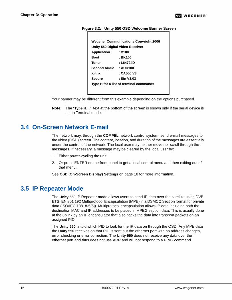
Figure 3.2: Unity 550 OSD Welcome Banner Screen
Your banner may be different from this example depending on the options purchased.
Note: The "Type H…" text at the bottom of the screen is shown only if the serial device is set to Terminal mode.
3.4 On-Screen Network E-mailThe network may, through the COMPEL network control system, send e-mail messages to the video (OSD) screen. The content, location, and duration of the messages are essentially under the control of the network. The local user may neither move nor scroll through the messages. If necessary, a message may be cleared by the local user by:
1. Either power-cycling the unit,
2. Or press ENTER on the front panel to get a local control menu and then exiting out of that menu.
See OSD (On-Screen Display) Settings on page 18 for more information.
3.5 IP Repeater ModeThe Unity 550 IP Repeater mode allows users to send IP data over the satellite using DVB ETSI EN 301 192 Multiprotocol Encapsulation (MPE) in a DSMCC Section format for private data (ISO/IEC 13818-5[5]). Multiprotocol encapsulation allows IP data including both the destination MAC and IP addresses to be placed in MPEG section data. This is usually done at the uplink by an IP encapsulator that also packs the data into transport packets on an assigned PID.
The Unity 550 is told which PID to look for the IP data on through the OSD. Any MPE data the Unity 550 receives on that PID is sent out the ethernet port with no address changes, error checking or error correction. The Unity 550 does not receive any data over the ethernet port and thus does not use ARP and will not respond to a PING command.
Wegener Communications Copyright 2006Unity 550 Digital Video ReceiverApplication : V100Boot : BK100Tuner : L64724DSecond Audio : AUD100Xilinx : CA550 V3Secure : Sin V3.03Type H for a list of terminal commands
www.wegener.com 800072-01 Rev. A 17
Unity 550 User’s Manual
3.6 On-Screen Display (OSD)Although the Unity 550 is set up at the factory, you can customize its settings to fit your system using the OSD and front-panel buttons. You may also view the existing settings and the various status and version fields by using the push buttons to navigate through the menus displayed on an attached monitor.
The OSD menus allow you to set up or change settings for these functions:
Carrier Status Carrier Select Software Version information Signal Strength Monitoring Serial Port device selection Audio Settings Data PID settings
OSD Setup The OSD information is contained in a 14-line x 40-character display in the video output from the Unity 550 receiver. View the OSD from a monitor connected to the video monitor output of the Unity 550 receiver.
1.From the front panel, use the right or left arrow buttons to navigate to OSD.
2.To display the OSD on the monitor, press ENTER.
Note: To exit the OSD, select EXIT from the Main Menu on the monitor. When a menu is first shown, the cursor is always placed on its first field.
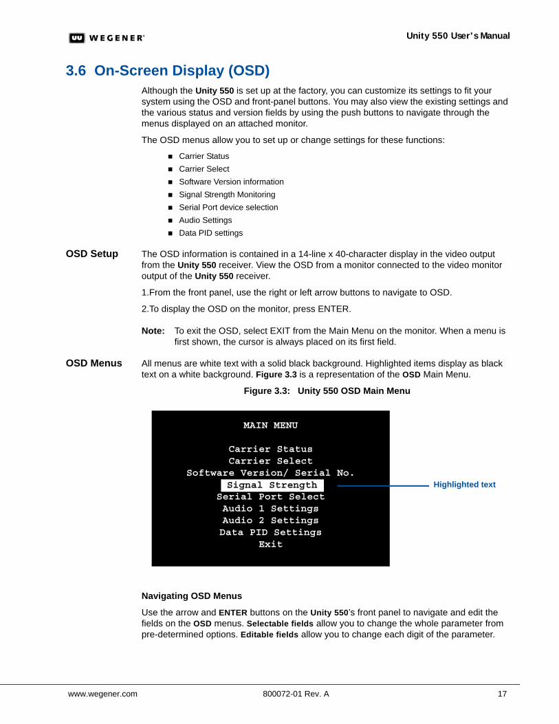
OSD Menus All menus are white text with a solid black background. Highlighted items display as black text on a white background. Figure 3.3 is a representation of the OSD Main Menu.
Figure 3.3: Unity 550 OSD Main Menu
Navigating OSD Menus
Use the arrow and ENTER buttons on the Unity 550’s front panel to navigate and edit the fields on the OSD menus. Selectable fields allow you to change the whole parameter from pre-determined options. Editable fields allow you to change each digit of the parameter.
MAIN MENU
Carrier StatusCarrier Select
Software Version/ Serial No.Signal Strength
Serial Port SelectAudio 1 SettingsAudio 2 SettingsData PID Settings
Exit
Signal Strength Highlighted text
Chapter 3: Operation
18 800072-01 Rev. A www.wegener.com
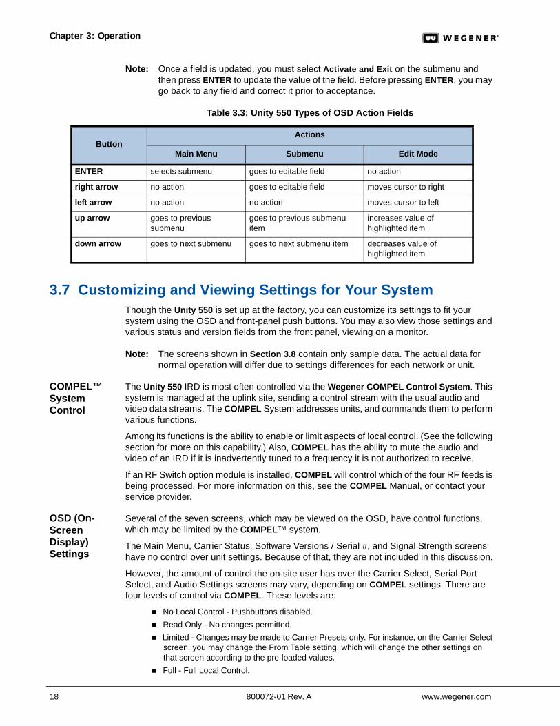
Note: Once a field is updated, you must select Activate and Exit on the submenu and then press ENTER to update the value of the field. Before pressing ENTER, you may go back to any field and correct it prior to acceptance.
Table 3.3: Unity 550 Types of OSD Action Fields
3.7 Customizing and Viewing Settings for Your SystemThough the Unity 550 is set up at the factory, you can customize its settings to fit your system using the OSD and front-panel push buttons. You may also view those settings and various status and version fields from the front panel, viewing on a monitor.
Note: The screens shown in Section 3.8 contain only sample data. The actual data for normal operation will differ due to settings differences for each network or unit.
COMPEL™ System Control
The Unity 550 IRD is most often controlled via the Wegener COMPEL Control System. This system is managed at the uplink site, sending a control stream with the usual audio and video data streams. The COMPEL System addresses units, and commands them to perform various functions.
Among its functions is the ability to enable or limit aspects of local control. (See the following section for more on this capability.) Also, COMPEL has the ability to mute the audio and video of an IRD if it is inadvertently tuned to a frequency it is not authorized to receive.
If an RF Switch option module is installed, COMPEL will control which of the four RF feeds is being processed. For more information on this, see the COMPEL Manual, or contact your service provider.
OSD (On-Screen Display) Settings
Several of the seven screens, which may be viewed on the OSD, have control functions, which may be limited by the COMPEL™ system.
The Main Menu, Carrier Status, Software Versions / Serial #, and Signal Strength screens have no control over unit settings. Because of that, they are not included in this discussion.
However, the amount of control the on-site user has over the Carrier Select, Serial Port Select, and Audio Settings screens may vary, depending on COMPEL settings. There are four levels of control via COMPEL. These levels are:
No Local Control - Pushbuttons disabled. Read Only - No changes permitted. Limited - Changes may be made to Carrier Presets only. For instance, on the Carrier Select
screen, you may change the From Table setting, which will change the other settings on that screen according to the pre-loaded values.
Full - Full Local Control.
ButtonActions
Main Menu Submenu Edit Mode
ENTER selects submenu goes to editable field no action
right arrow no action goes to editable field moves cursor to right
left arrow no action no action moves cursor to left
up arrow goes to previous submenu
goes to previous submenu item
increases value of highlighted item
down arrow goes to next submenu goes to next submenu item decreases value of highlighted item
www.wegener.com 800072-01 Rev. A 19
Unity 550 User’s Manual
Carrier Status Refer to Table 3.3: Unity 550 Types of OSD Action Fields on page 18 for updating specific fields
Carrier Status is a read-only screen. (No changes can be made here.)
While on the Main Menu page:
1. Press the down arrow button until Carrier Status is highlighted.
2. Press ENTER.
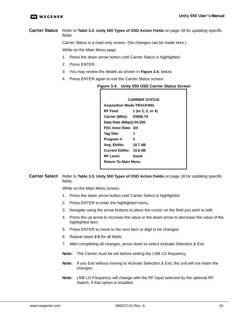
3. You may review the details as shown in Figure 3.4, below.
4. Press ENTER again to exit the Carrier Status screen.
Figure 3.4: Unity 550 OSD Carrier Status Screen
Carrier Select Refer to Table 3.3: Unity 550 Types of OSD Action Fields on page 18 for updating specific fields.
While on the Main Menu screen,
1. Press the down arrow button until Carrier Select is highlighted
2. Press ENTER to enter the highlighted menu.
3. Navigate using the arrow buttons to place the cursor on the field you wish to edit.
4. Press the up arrow to increase the value or the down arrow to decrease the value of the highlighted item.
5. Press ENTER to move to the next item or digit to be changed.
6. Repeat steps 3-5 for all fields.
7. After completing all changes, arrow down to select Activate Selection & Exit.
Note: The Carrier must be set before setting the LNB LO frequency.
Note: If you Exit without moving to Activate Selection & Exit, the unit will not retain the changes.
Note: LNB LO Frequency will change with the RF Input selected by the optional RF Switch, if that option is installed.
CARRIER STATUSAcquisition Mode:TRACKINGRF Feed 1 (or 2, 3, or 4)Carrier (MHz): 03906.75Data Rate (Mbps):04.250FEC Inner Rate: 3/4Tag Site: 1Program #: 3Avg. Eb/No: 10.7 dBCurrent Eb/No: 10.8 dBRF Level: GoodReturn To Main Menu
Chapter 3: Operation
20 800072-01 Rev. A www.wegener.com
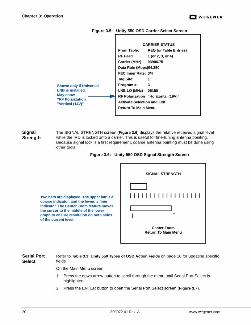
Figure 3.5: Unity 550 OSD Carrier Select Screen
Signal Strength
The SIGNAL STRENGTH screen (Figure 3.6) displays the relative received signal level while the IRD is locked onto a carrier. This is useful for fine-tuning antenna pointing. Because signal lock is a first requirement, coarse antenna pointing must be done using other tools.
Figure 3.6: Unity 550 OSD Signal Strength Screen
Serial Port Select
Refer to Table 3.3: Unity 550 Types of OSD Action Fields on page 18 for updating specific fields
On the Main Menu screen:
1. Press the down arrow button to scroll through the menu until Serial Port Select is highlighted.
2. Press the ENTER button to open the Serial Port Select screen (Figure 3.7).
CARRIER STATUSFrom Table: REQ (or Table Entries)RF Feed 1 (or 2, 3, or 4)Carrier (MHz): 03906.75Data Rate (Mbps)04.250FEC Inner Rate: 3/4Tag Site: 1Program #: 3LNB LO (MHz) 05150RF Polarization “Horizontal (19V)”Activate Selection and ExitReturn To Main Menu
Shown only if Universal LNB is installed. May show "RF Polarization "Vertical (14V)"
SIGNAL STRENGTH
Center ZoomReturn To Main Menu
Two bars are displayed. The upper bar is a coarse indicator, and the lower, a finer indicator. The Center Zoom feature moves the cursor to the middle of the lower graph to ensure resolution on both sides of the current level.
www.wegener.com 800072-01 Rev. A 21
Unity 550 User’s Manual
3. Press the ENTER button to move to the available device options for the serial port (Terminal, Modem, Printer, or Aux Data).
4. Press the right arrow button to move through the options until the desired one is highlighted.
5. Press ENTER to edit the selected option.
6. Press ENTER until the desired value is displayed.
7. Press the down arrow button to move to Activate Settings.
8. Press ENTER to save your selections to memory.
9. Press the down arrow button to move to Return To Main Menu.
10. Press ENTER to return to the Main Menu screen.
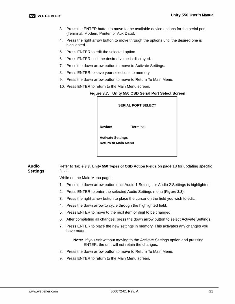
Figure 3.7: Unity 550 OSD Serial Port Select Screen
Audio Settings
Refer to Table 3.3: Unity 550 Types of OSD Action Fields on page 18 for updating specific fields
While on the Main Menu page:
1. Press the down arrow button until Audio 1 Settings or Audio 2 Settings is highlighted
2. Press ENTER to enter the selected Audio Settings menu (Figure 3.8).
3. Press the right arrow button to place the cursor on the field you wish to edit.
4. Press the down arrow to cycle through the highlighted field.
5. Press ENTER to move to the next item or digit to be changed.
6. After completing all changes, press the down arrow button to select Activate Settings.
7. Press ENTER to place the new settings in memory. This activates any changes you have made.
Note: If you exit without moving to the Activate Settings option and pressing ENTER, the unit will not retain the changes.
8. Press the down arrow button to move to Return To Main Menu.
9. Press ENTER to return to the Main Menu screen.
SERIAL PORT SELECT
Device: Terminal
Activate SettingsReturn to Main Menu
Chapter 3: Operation
22 800072-01 Rev. A www.wegener.com
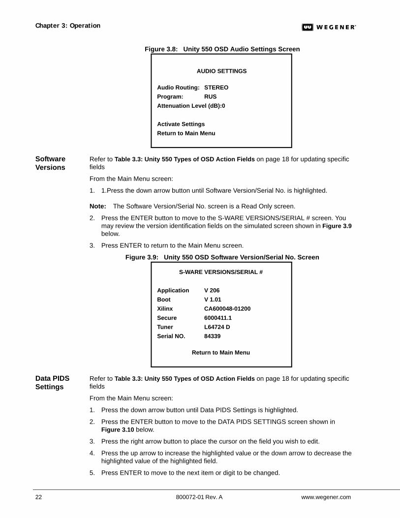
Figure 3.8: Unity 550 OSD Audio Settings Screen
Software Versions
Refer to Table 3.3: Unity 550 Types of OSD Action Fields on page 18 for updating specific fields
From the Main Menu screen:
1. 1.Press the down arrow button until Software Version/Serial No. is highlighted.
Note: The Software Version/Serial No. screen is a Read Only screen.
2. Press the ENTER button to move to the S-WARE VERSIONS/SERIAL # screen. You may review the version identification fields on the simulated screen shown in Figure 3.9 below.
3. Press ENTER to return to the Main Menu screen.
Figure 3.9: Unity 550 OSD Software Version/Serial No. Screen
Data PIDS Settings
Refer to Table 3.3: Unity 550 Types of OSD Action Fields on page 18 for updating specific fields
From the Main Menu screen:
1. Press the down arrow button until Data PIDS Settings is highlighted.
2. Press the ENTER button to move to the DATA PIDS SETTINGS screen shown in Figure 3.10 below.
3. Press the right arrow button to place the cursor on the field you wish to edit.
4. Press the up arrow to increase the highlighted value or the down arrow to decrease the highlighted value of the highlighted field.
5. Press ENTER to move to the next item or digit to be changed.
AUDIO SETTINGS
Audio Routing: STEREOProgram: RUSAttenuation Level (dB):0
Activate SettingsReturn to Main Menu
S-WARE VERSIONS/SERIAL #
Application V 206Boot V 1.01Xilinx CA600048-01200Secure 6000411.1Tuner L64724 DSerial NO. 84339
Return to Main Menu
www.wegener.com 800072-01 Rev. A 23
Unity 550 User’s Manual
6. After completing all changes, Press ENTER to select Activate Settings.
7. Press ENTER to place the new settings in memory. This activates any changes you have made.
Note: If you exit without moving to the Activate Settings option and pressing ENTER, the unit will not retain the changes.
8. Press the down arrow button to move to Return To Main Menu.
9. Press ENTER to return to the Main Menu screen.
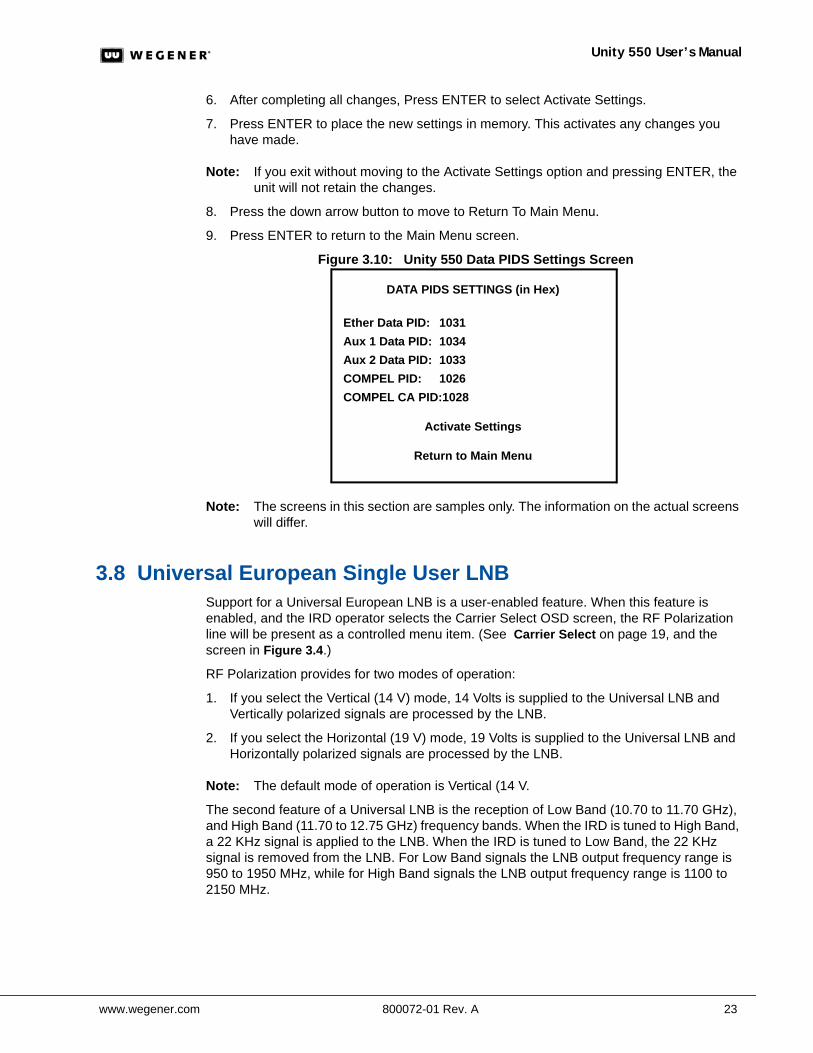
Figure 3.10: Unity 550 Data PIDS Settings Screen
Note: The screens in this section are samples only. The information on the actual screens will differ.
3.8 Universal European Single User LNBSupport for a Universal European LNB is a user-enabled feature. When this feature is enabled, and the IRD operator selects the Carrier Select OSD screen, the RF Polarization line will be present as a controlled menu item. (See Carrier Select on page 19, and the screen in Figure 3.4.)
RF Polarization provides for two modes of operation:
1. If you select the Vertical (14 V) mode, 14 Volts is supplied to the Universal LNB and Vertically polarized signals are processed by the LNB.
2. If you select the Horizontal (19 V) mode, 19 Volts is supplied to the Universal LNB and Horizontally polarized signals are processed by the LNB.
Note: The default mode of operation is Vertical (14 V.
The second feature of a Universal LNB is the reception of Low Band (10.70 to 11.70 GHz), and High Band (11.70 to 12.75 GHz) frequency bands. When the IRD is tuned to High Band, a 22 KHz signal is applied to the LNB. When the IRD is tuned to Low Band, the 22 KHz signal is removed from the LNB. For Low Band signals the LNB output frequency range is 950 to 1950 MHz, while for High Band signals the LNB output frequency range is 1100 to 2150 MHz.
DATA PIDS SETTINGS (in Hex)
Ether Data PID: 1031Aux 1 Data PID: 1034Aux 2 Data PID: 1033COMPEL PID: 1026COMPEL CA PID:1028
Activate Settings
Return to Main Menu

Chapter 3: Operation
24 800072-01 Rev. A www.wegener.com
www.wegener.com 800072-01 Rev. A 25
Unity 550 User’s Manual
CHAPTER 4 SEARCH FUNCTIONS
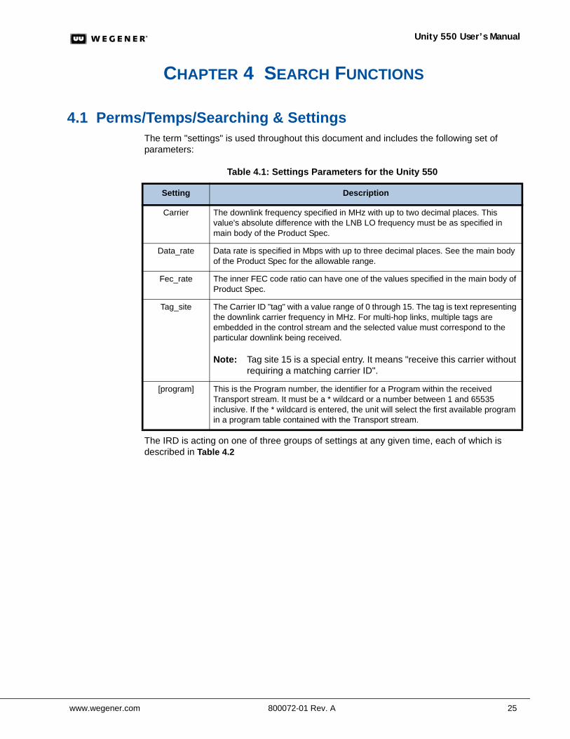
4.1 Perms/Temps/Searching & SettingsThe term "settings" is used throughout this document and includes the following set of parameters:
Table 4.1: Settings Parameters for the Unity 550
The IRD is acting on one of three groups of settings at any given time, each of which is described in Table 4.2
Setting Description
Carrier The downlink frequency specified in MHz with up to two decimal places. This value's absolute difference with the LNB LO frequency must be as specified in main body of the Product Spec.
Data_rate Data rate is specified in Mbps with up to three decimal places. See the main body of the Product Spec for the allowable range.
Fec_rate The inner FEC code ratio can have one of the values specified in the main body of Product Spec.
Tag_site The Carrier ID "tag" with a value range of 0 through 15. The tag is text representing the downlink carrier frequency in MHz. For multi-hop links, multiple tags are embedded in the control stream and the selected value must correspond to the particular downlink being received.
Note: Tag site 15 is a special entry. It means "receive this carrier without requiring a matching carrier ID".
[program] This is the Program number, the identifier for a Program within the received Transport stream. It must be a * wildcard or a number between 1 and 65535 inclusive. If the * wildcard is entered, the unit will select the first available program in a program table contained with the Transport stream.
Chapter 4: Search Functions
26 800072-01 Rev. A www.wegener.com
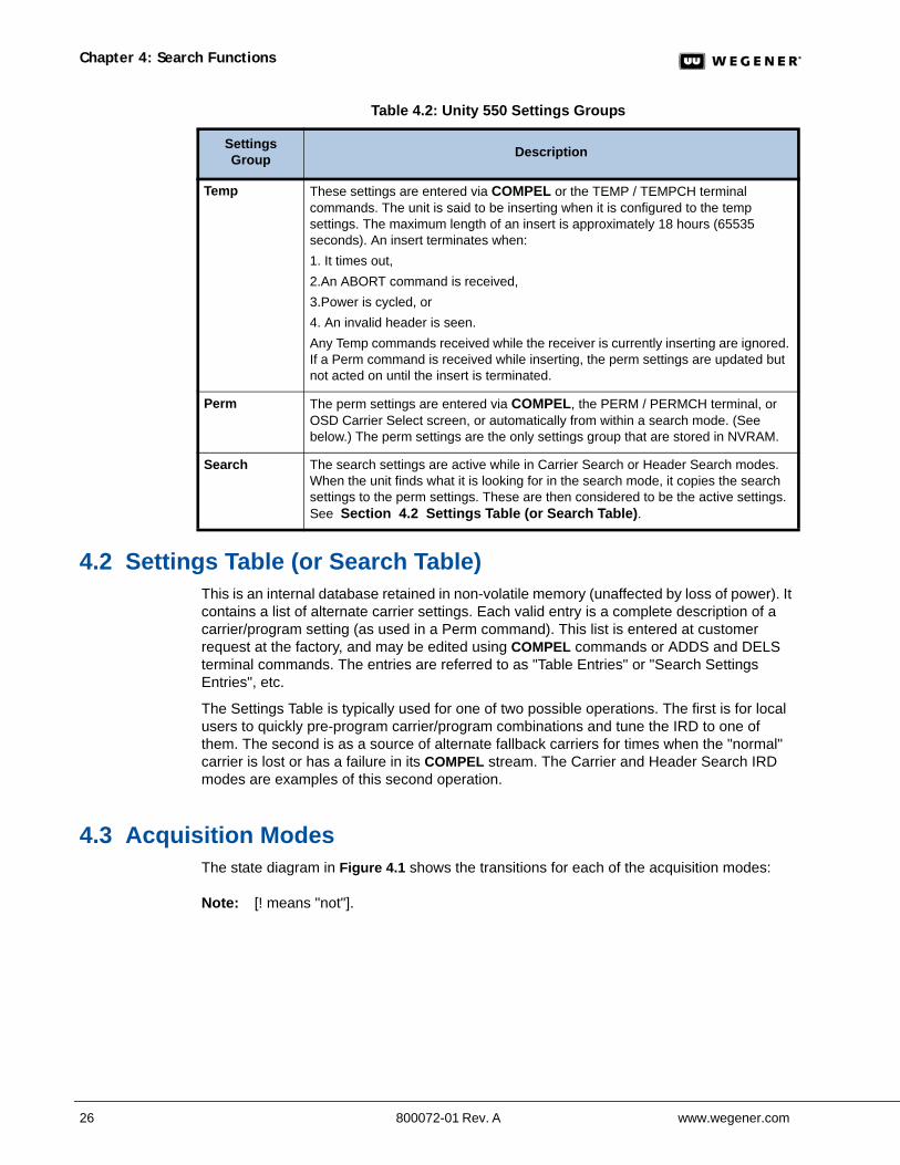
Table 4.2: Unity 550 Settings Groups
4.2 Settings Table (or Search Table)This is an internal database retained in non-volatile memory (unaffected by loss of power). It contains a list of alternate carrier settings. Each valid entry is a complete description of a carrier/program setting (as used in a Perm command). This list is entered at customer request at the factory, and may be edited using COMPEL commands or ADDS and DELS terminal commands. The entries are referred to as "Table Entries" or "Search Settings Entries", etc.
The Settings Table is typically used for one of two possible operations. The first is for local users to quickly pre-program carrier/program combinations and tune the IRD to one of them. The second is as a source of alternate fallback carriers for times when the "normal" carrier is lost or has a failure in its COMPEL stream. The Carrier and Header Search IRD modes are examples of this second operation.
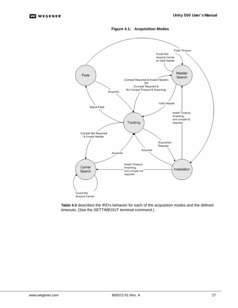
4.3 Acquisition ModesThe state diagram in Figure 4.1 shows the transitions for each of the acquisition modes:
Note: [! means "not"].
Settings Group Description
Temp These settings are entered via COMPEL or the TEMP / TEMPCH terminal commands. The unit is said to be inserting when it is configured to the temp settings. The maximum length of an insert is approximately 18 hours (65535 seconds). An insert terminates when:1. It times out, 2.An ABORT command is received, 3.Power is cycled, or4. An invalid header is seen. Any Temp commands received while the receiver is currently inserting are ignored. If a Perm command is received while inserting, the perm settings are updated but not acted on until the insert is terminated.
Perm The perm settings are entered via COMPEL, the PERM / PERMCH terminal, or OSD Carrier Select screen, or automatically from within a search mode. (See below.) The perm settings are the only settings group that are stored in NVRAM.
Search The search settings are active while in Carrier Search or Header Search modes. When the unit finds what it is looking for in the search mode, it copies the search settings to the perm settings. These are then considered to be the active settings. See Section 4.2 Settings Table (or Search Table).
www.wegener.com 800072-01 Rev. A 27
Unity 550 User’s Manual
Figure 4.1: Acquisition Modes
Table 4.3 describes the IRD's behavior for each of the acquisition modes and the defined timeouts. (See the SETTIMEOUT terminal command.)
Chapter 4: Search Functions
28 800072-01 Rev. A www.wegener.com
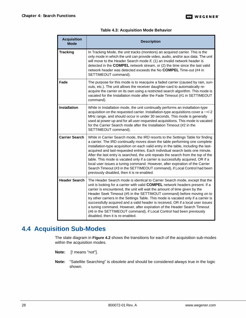
Table 4.3: Acquisition Mode Behavior
4.4 Acquisition Sub-Modes The state diagram in Figure 4.2 shows the transitions for each of the acquisition sub-modes within the acquisition modes.
Note: [! means "not"].
Note: "Satellite Searching" is obsolete and should be considered always true in the logic shown.
Acquisition Mode Description
Tracking In Tracking Mode, the unit tracks (monitors) an acquired carrier. This is the only mode in which the unit can provide video, audio, and/or aux data. The unit will move to the Header Search mode if, (1) an invalid network header is detected in the COMPEL network stream, or (2) the time since the last valid network header was detected exceeds the No COMPEL Time-out (#4 in SETTIMEOUT command).
Fade The purpose for this mode is to reacquire a faded carrier (caused by rain, sun-outs, etc.). The unit allows the receiver daughter-card to automatically re-acquire the carrier on its own using a restricted search algorithm. This mode is vacated for the Installation mode after the Fade Timeout (#1 in SETTIMEOUT command).
Installation While in Installation mode, the unit continually performs an installation-type acquisition on the requested carrier. Installation-type acquisitions cover a ~+/-2 MHz range, and should occur in under 30 seconds. This mode is generally used at power up and for all user-requested acquisitions. This mode is vacated for the Carrier Search mode after the Installation Timeout (#2 in the SETTIMEOUT command).
Carrier Search While in Carrier Search mode, the IRD resorts to the Settings Table for finding a carrier. The IRD continually moves down the table performing one complete installation-type acquisition on each valid entry in the table, including the last-acquired and last-requested entries. Each individual search lasts one minute. After the last entry is searched, the unit repeats the search from the top of the table. This mode is vacated only if a carrier is successfully acquired, OR if a local user issues a tuning command. However, after expiration of the Carrier Search Timeout (#3 in the SETTIMEOUT command), if Local Control had been previously disabled, then it is re-enabled.
Header Search The Header Search mode is identical to Carrier Search mode, except that the unit is looking for a carrier with valid COMPEL network headers present. If a carrier is encountered, the unit will wait the amount of time given by the Header Seek Timeout (#5 in the SETTIMOUT command) before moving on to try other carriers in the Settings Table. This mode is vacated only if a carrier is successfully acquired and a valid header is received, OR if a local user issues a tuning command. However, after expiration of the Header Search Timeout (#6 in the SETTIMEOUT command), if Local Control had been previously disabled, then it is re-enabled.
www.wegener.com 800072-01 Rev. A 29
Unity 550 User’s Manual
Figure 4.2: Acquisition Sub-Modes
4.5 Signal Quality MonitoringThe IRD provides the following signal quality information while tracking a carrier only:
Chapter 4: Search Functions
30 800072-01 Rev. A www.wegener.com
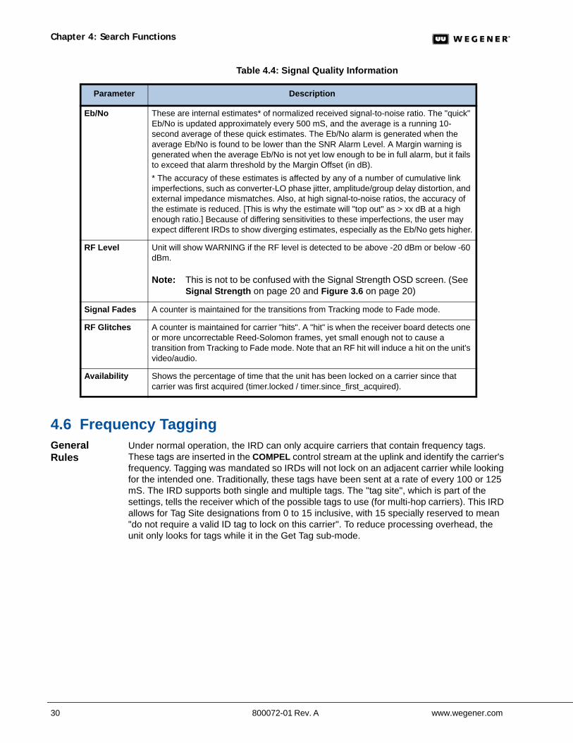
Table 4.4: Signal Quality Information
4.6 Frequency TaggingGeneral Rules
Under normal operation, the IRD can only acquire carriers that contain frequency tags. These tags are inserted in the COMPEL control stream at the uplink and identify the carrier's frequency. Tagging was mandated so IRDs will not lock on an adjacent carrier while looking for the intended one. Traditionally, these tags have been sent at a rate of every 100 or 125 mS. The IRD supports both single and multiple tags. The "tag site", which is part of the settings, tells the receiver which of the possible tags to use (for multi-hop carriers). This IRD allows for Tag Site designations from 0 to 15 inclusive, with 15 specially reserved to mean "do not require a valid ID tag to lock on this carrier". To reduce processing overhead, the unit only looks for tags while it in the Get Tag sub-mode.
Parameter Description
Eb/No These are internal estimates* of normalized received signal-to-noise ratio. The "quick" Eb/No is updated approximately every 500 mS, and the average is a running 10-second average of these quick estimates. The Eb/No alarm is generated when the average Eb/No is found to be lower than the SNR Alarm Level. A Margin warning is generated when the average Eb/No is not yet low enough to be in full alarm, but it fails to exceed that alarm threshold by the Margin Offset (in dB).* The accuracy of these estimates is affected by any of a number of cumulative link imperfections, such as converter-LO phase jitter, amplitude/group delay distortion, and external impedance mismatches. Also, at high signal-to-noise ratios, the accuracy of the estimate is reduced. [This is why the estimate will "top out" as > xx dB at a high enough ratio.] Because of differing sensitivities to these imperfections, the user may expect different IRDs to show diverging estimates, especially as the Eb/No gets higher.
RF Level Unit will show WARNING if the RF level is detected to be above -20 dBm or below -60 dBm.
Note: This is not to be confused with the Signal Strength OSD screen. (See Signal Strength on page 20 and Figure 3.6 on page 20)
Signal Fades A counter is maintained for the transitions from Tracking mode to Fade mode.
RF Glitches A counter is maintained for carrier "hits". A "hit" is when the receiver board detects one or more uncorrectable Reed-Solomon frames, yet small enough not to cause a transition from Tracking to Fade mode. Note that an RF hit will induce a hit on the unit's video/audio.
Availability Shows the percentage of time that the unit has been locked on a carrier since that carrier was first acquired (timer.locked / timer.since_first_acquired).
www.wegener.com 800072-01 Rev. A 31
Unity 550 User’s Manual
CHAPTER 5 CUSTOMER SERVICE
5.1 Warrantyhe following warranty applies to all Wegener Communications products including the Unity 550:
All Wegener Communications products are warranted against defective materials and workmanship for a period of one year after shipment to customer. Wegener Communications' obligation under this warranty is limited to repairing or, at Wegener Communications' option, replacing parts, subassemblies, or entire assemblies. Wegener Communications shall not be liable for any special, indirect, or consequential damages. This warranty does not cover parts or equipment which have been subject to misuse, negligence, or accident by the customer during use. All shipping costs for warranty repairs will be prepaid by the customer. There are no other warranties, express or implied, except as stated herein.
5.2 Technical SupportIf the unit should fail to perform as described, if you need help resolving problems with your Unity 550, or for questions about obtaining service for your Unity 550, please contact Wegener Communications Customer Service at (770) 814-4057, Fax (678) 624-0294, or e-mail [email protected].
To return a product for service:
1. Obtain a Return Material Authorization (RMA) number by completing and faxing a copy of the RMA Request Form to (678) 624-0294. Or you may e-mail the same information to: [email protected].
2. To help us identify and control returned units, plainly write the RMA number on the outside of the product-shipping container. This will help us return your unit to you as quickly as possible.
3. Return the product, freight prepaid, to the address below:
Note: All returned material must be shipped freight prepaid. C.O.D. shipments will not be accepted.
Service Department RMA# ________Wegener Communications, Inc.359 Curie Drive
Alpharetta, GA 30005

Chapter 5: Customer Service
32 800072-01 Rev. A www.wegener.com
www.wegener.com 800072-01 Rev. A 33
Unity 550 User’s Manual
APPENDIX A: TERMINAL/MODEM MODE
Terminal/Modem CommandsCommands listed in this section detail command syntax and action taken. Commands consist of a command field and a parameter field. Each command field and parameter field is separated from others by a space. Optional parameters are indicated by square brackets, [ ], and conditional parameters are indicated by braces, { }.
For example, COMMAND_NAME parameter1 {parameter2} [parameter3] indicates that parameter1 must be entered, parameter2 entered only when a certain condition is met (certain option is installed, etc.), and parameter3 is optional. Both commands and parameters may be entered in upper or lower case; the interface is not case-sensitive.
Incorrect or incomplete commands result in Invalid Command responses being displayed at the terminal. Parameter errors on User commands generate Invalid parameter name responses, where parameter name is the name of the incorrectly entered parameter.
Network-Enabled Local Control Commands
These commands are allowed only if local control is enabled and are listed in Table A.1 below. Commands that are always functional are discussed in Local Control Commands on page 35 and listed in Table A.2.
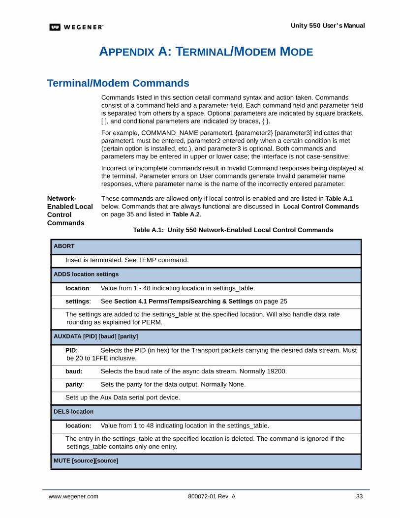
Table A.1: Unity 550 Network-Enabled Local Control Commands
ABORT
Insert is terminated. See TEMP command.
ADDS location settings
location: Value from 1 - 48 indicating location in settings_table.
settings: See Section 4.1 Perms/Temps/Searching & Settings on page 25
The settings are added to the settings_table at the specified location. Will also handle data rate rounding as explained for PERM.
AUXDATA [PID] [baud] [parity]
PID: Selects the PID (in hex) for the Transport packets carrying the desired data stream. Must be 20 to 1FFE inclusive.
baud: Selects the baud rate of the async data stream. Normally 19200.
parity: Sets the parity for the data output. Normally None.
Sets up the Aux Data serial port device.
DELS location
location: Value from 1 to 48 indicating location in the settings_table.
The entry in the settings_table at the specified location is deleted. The command is ignored if the settings_table contains only one entry.
MUTE [source][source]
34 800072-01 Rev. A www.wegener.com
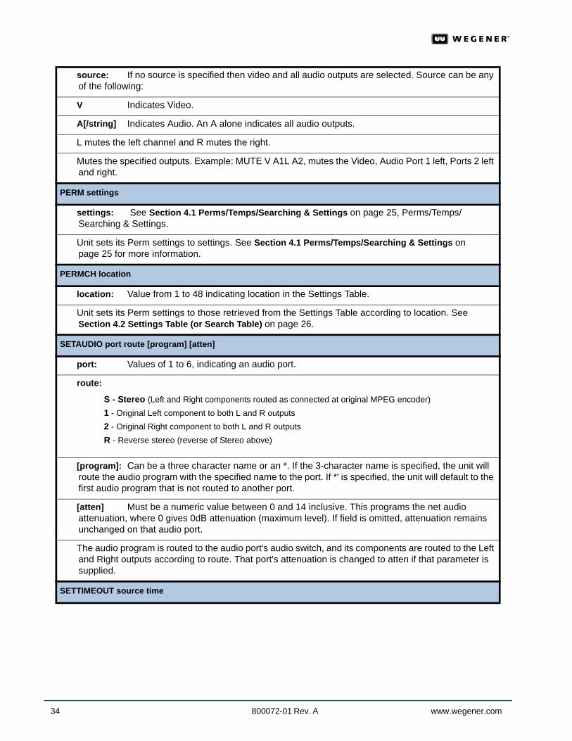
source: If no source is specified then video and all audio outputs are selected. Source can be any of the following:
V Indicates Video.
A[/string] Indicates Audio. An A alone indicates all audio outputs.
L mutes the left channel and R mutes the right.
Mutes the specified outputs. Example: MUTE V A1L A2, mutes the Video, Audio Port 1 left, Ports 2 left and right.
PERM settings
settings: See Section 4.1 Perms/Temps/Searching & Settings on page 25, Perms/Temps/Searching & Settings.
Unit sets its Perm settings to settings. See Section 4.1 Perms/Temps/Searching & Settings on page 25 for more information.
PERMCH location
location: Value from 1 to 48 indicating location in the Settings Table.
Unit sets its Perm settings to those retrieved from the Settings Table according to location. See Section 4.2 Settings Table (or Search Table) on page 26.
SETAUDIO port route [program] [atten]
port: Values of 1 to 6, indicating an audio port.
route:
[program]: Can be a three character name or an *. If the 3-character name is specified, the unit will route the audio program with the specified name to the port. If *' is specified, the unit will default to the first audio program that is not routed to another port.
[atten] Must be a numeric value between 0 and 14 inclusive. This programs the net audio attenuation, where 0 gives 0dB attenuation (maximum level). If field is omitted, attenuation remains unchanged on that audio port.
The audio program is routed to the audio port's audio switch, and its components are routed to the Left and Right outputs according to route. That port's attenuation is changed to atten if that parameter is supplied.
SETTIMEOUT source time
S - Stereo (Left and Right components routed as connected at original MPEG encoder)1 - Original Left component to both L and R outputs2 - Original Right component to both L and R outputsR - Reverse stereo (reverse of Stereo above)
www.wegener.com 800072-01 Rev. A 35
Unity 550 User’s Manual
Local Control Commands
Local control commands that are always functional at the Unity 550 Terminal are listed in Table A.2. Commands allowed only if local control is enabled by the COMPEL network and are listed in Table A.1 above.
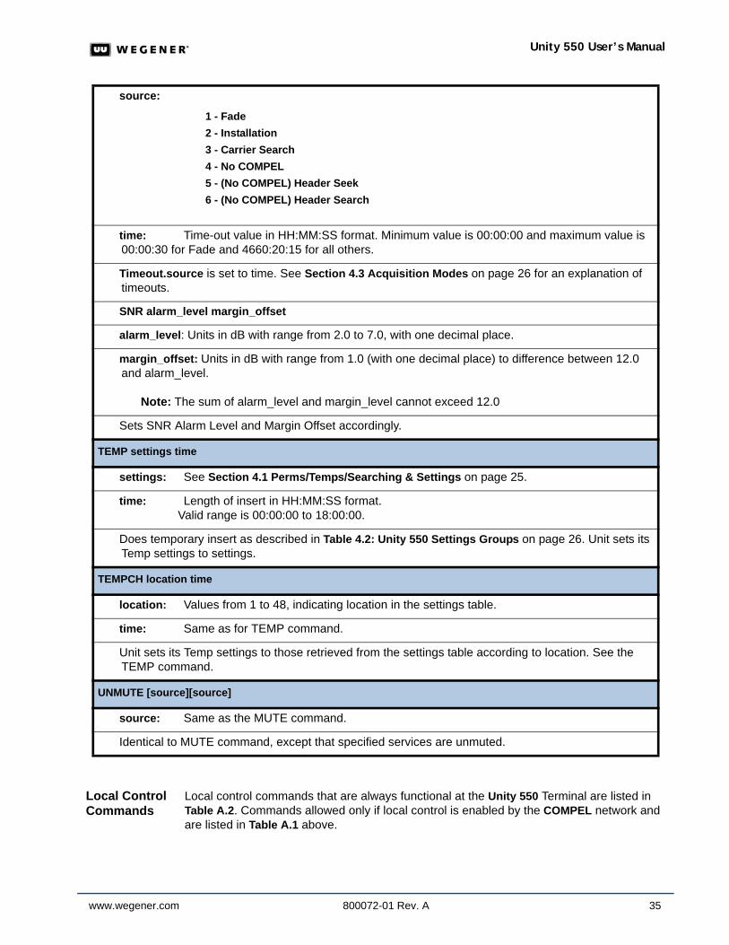
source:
time: Time-out value in HH:MM:SS format. Minimum value is 00:00:00 and maximum value is 00:00:30 for Fade and 4660:20:15 for all others.
Timeout.source is set to time. See Section 4.3 Acquisition Modes on page 26 for an explanation of timeouts.
SNR alarm_level margin_offset
alarm_level: Units in dB with range from 2.0 to 7.0, with one decimal place.
margin_offset: Units in dB with range from 1.0 (with one decimal place) to difference between 12.0 and alarm_level.
Note: The sum of alarm_level and margin_level cannot exceed 12.0
Sets SNR Alarm Level and Margin Offset accordingly.
TEMP settings time
settings: See Section 4.1 Perms/Temps/Searching & Settings on page 25.
time: Length of insert in HH:MM:SS format. Valid range is 00:00:00 to 18:00:00.
Does temporary insert as described in Table 4.2: Unity 550 Settings Groups on page 26. Unit sets its Temp settings to settings.
TEMPCH location time
location: Values from 1 to 48, indicating location in the settings table.
time: Same as for TEMP command.
Unit sets its Temp settings to those retrieved from the settings table according to location. See the TEMP command.
UNMUTE [source][source]
source: Same as the MUTE command.
Identical to MUTE command, except that specified services are unmuted.
1 - Fade2 - Installation3 - Carrier Search4 - No COMPEL5 - (No COMPEL) Header Seek6 - (No COMPEL) Header Search
36 800072-01 Rev. A www.wegener.com
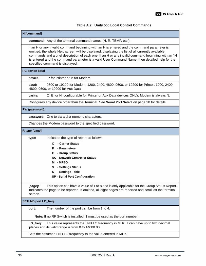
Table A.2: Unity 550 Local Control Commands
H [command]
command: Any of the terminal command names (H, R, TEMP, etc.).
If an H or any invalid command beginning with an H is entered and the command parameter is omitted, the whole Help screen will be displayed, displaying the list of all currently available commands and a brief description of each one. If an H or any invalid command beginning with an ' H is entered and the command parameter is a valid User Command Name, then detailed help for the specified command is displayed.
PC device baud
device: P for Printer or M for Modem.
baud: 9600 or 19200 for Modem; 1200, 2400, 4800, 9600, or 19200 for Printer; 1200, 2400, 4800, 9600, or 19200 for Aux Data
parity: O, E, or N, configurable for Printer or Aux Data devices ONLY. Modem is always N.
Configures any device other than the Terminal. See Serial Port Select on page 20 for details.
PW (password):
password: One to six alpha-numeric characters.
Changes the Modem password to the specified password.
R type [page]
type: Indicates the type of report as follows:
[page]: This option can have a value of 1 to 8 and is only applicable for the Group Status Report. Indicates the page to be reported. If omitted, all eight pages are reported and scroll off the terminal screen.
SETLNB port LO_freq
port: The number of the port can be from 1 to 4.
Note: If no RF Switch is installed, 1 must be used as the port number.
LO_freq: This value represents the LNB LO frequency in MHz. It can have up to two decimal places and its valid range is from 0 to 14000.00.
Sets the assumed LNB LO frequency to the value entered in MHz.
C - Carrier StatusP - ParametersG - Group StatusNC - Network Controller StatusM - MPEGS - Settings StatusS - Settings TableSP - Serial Port Configuration
www.wegener.com 800072-01 Rev. A 37
Unity 550 User’s Manual
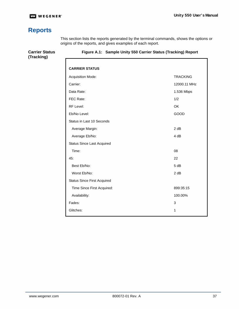
ReportsThis section lists the reports generated by the terminal commands, shows the options or origins of the reports, and gives examples of each report.
Carrier Status (Tracking)
Figure A.1: Sample Unity 550 Carrier Status (Tracking) Report
CARRIER STATUS
Acquisition Mode: TRACKING
Carrier: 12000.11 MHz
Data Rate: 1.536 Mbps
FEC Rate: 1/2
RF Level: OK
Eb/No Level: GOOD
Status in Last 10 Seconds
Average Margin: 2 dB
Average Eb/No: 4 dB
Status Since Last Acquired
Time: 08
45: 22
Best Eb/No: 5 dB
Worst Eb/No: 2 dB
Status Since First Acquired
Time Since First Acquired: 899:35:15
Availability: 100.00%
Fades: 3
Glitches: 1
38 800072-01 Rev. A www.wegener.com
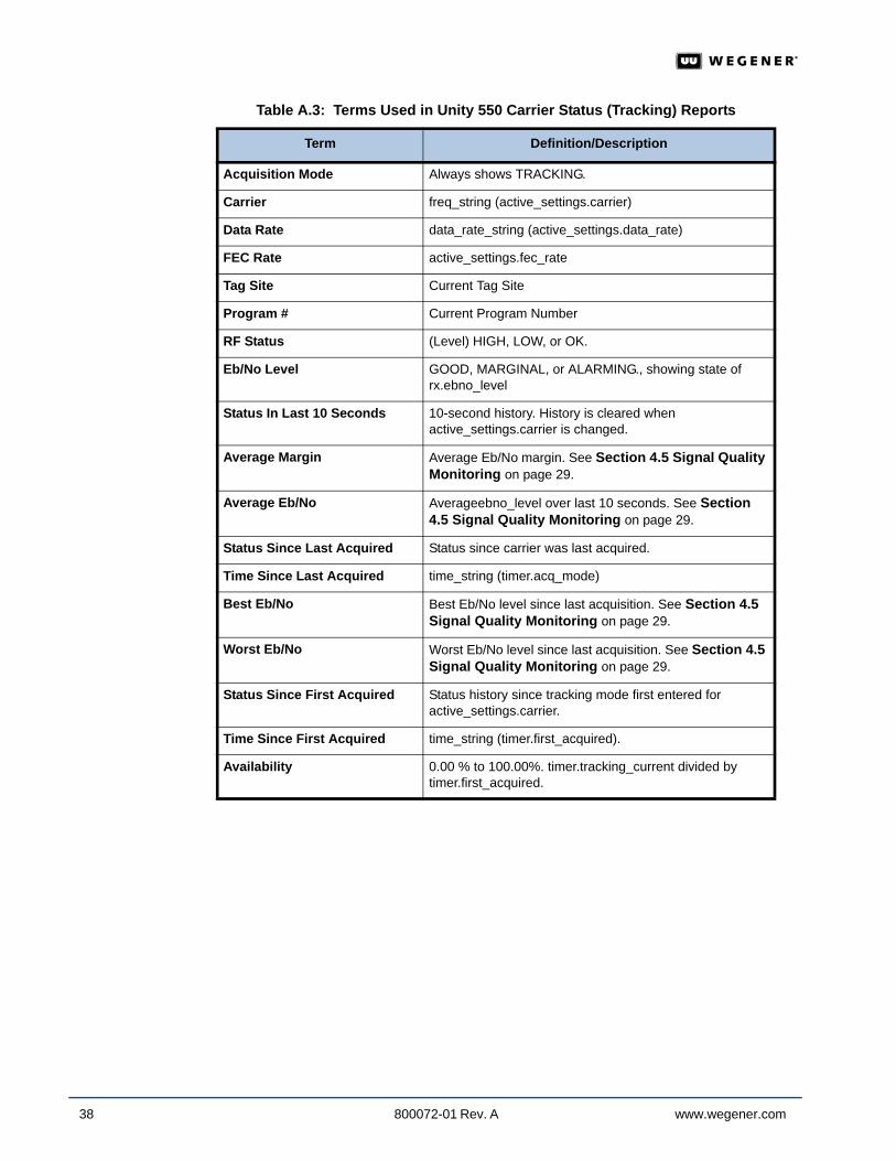
Table A.3: Terms Used in Unity 550 Carrier Status (Tracking) Reports
Term Definition/Description
Acquisition Mode Always shows TRACKING.
Carrier freq_string (active_settings.carrier)
Data Rate data_rate_string (active_settings.data_rate)
FEC Rate active_settings.fec_rate
Tag Site Current Tag Site
Program # Current Program Number
RF Status (Level) HIGH, LOW, or OK.
Eb/No Level GOOD, MARGINAL, or ALARMING., showing state of rx.ebno_level
Status In Last 10 Seconds 10-second history. History is cleared when active_settings.carrier is changed.
Average Margin Average Eb/No margin. See Section 4.5 Signal Quality Monitoring on page 29.
Average Eb/No Averageebno_level over last 10 seconds. See Section 4.5 Signal Quality Monitoring on page 29.
Status Since Last Acquired Status since carrier was last acquired.
Time Since Last Acquired time_string (timer.acq_mode)
Best Eb/No Best Eb/No level since last acquisition. See Section 4.5 Signal Quality Monitoring on page 29.
Worst Eb/No Worst Eb/No level since last acquisition. See Section 4.5 Signal Quality Monitoring on page 29.
Status Since First Acquired Status history since tracking mode first entered for active_settings.carrier.
Time Since First Acquired time_string (timer.first_acquired).
Availability 0.00 % to 100.00%. timer.tracking_current divided by timer.first_acquired.
www.wegener.com 800072-01 Rev. A 39
Unity 550 User’s Manual
Carrier Status (Not Tracking)
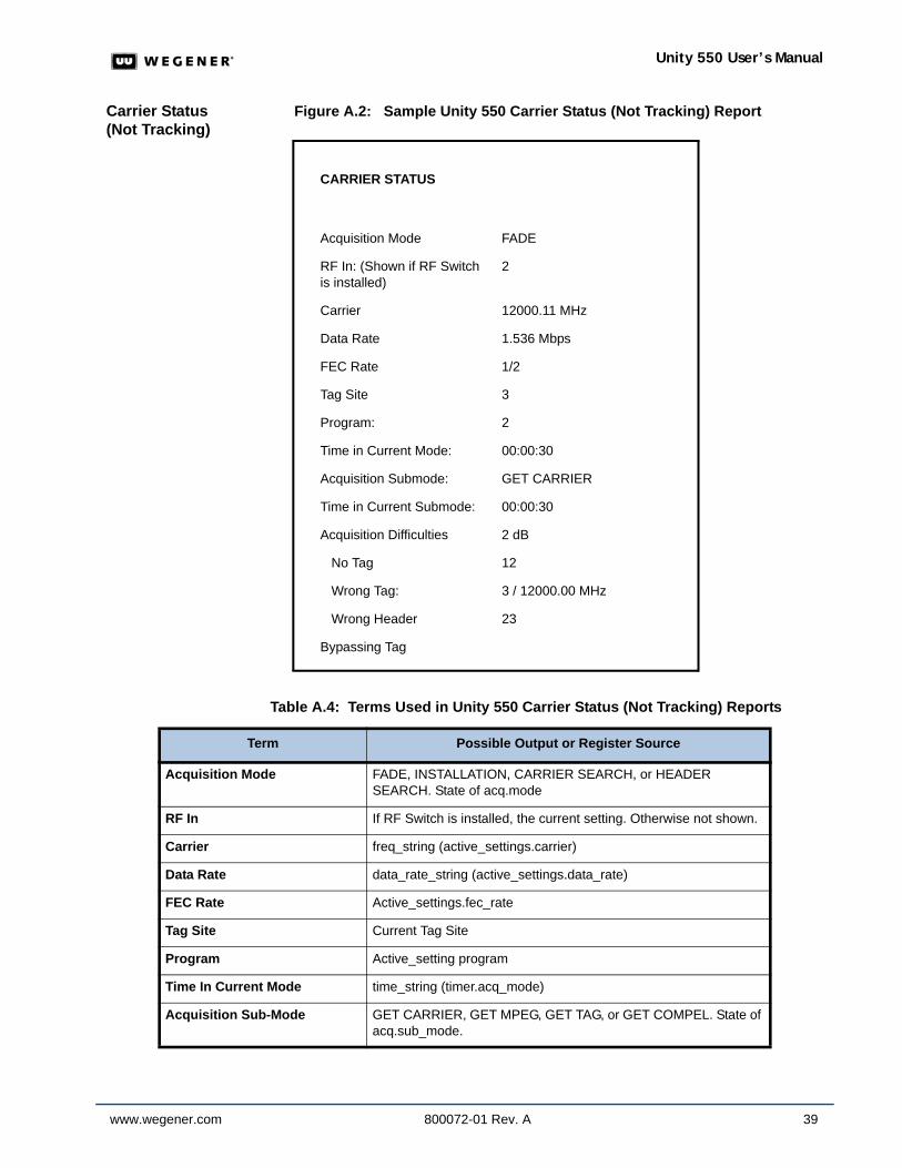
Figure A.2: Sample Unity 550 Carrier Status (Not Tracking) Report
Table A.4: Terms Used in Unity 550 Carrier Status (Not Tracking) Reports
CARRIER STATUS
Acquisition Mode FADE
RF In: (Shown if RF Switch is installed)
2
Carrier 12000.11 MHz
Data Rate 1.536 Mbps
FEC Rate 1/2
Tag Site 3
Program: 2
Time in Current Mode: 00:00:30
Acquisition Submode: GET CARRIER
Time in Current Submode: 00:00:30
Acquisition Difficulties 2 dB
No Tag 12
Wrong Tag: 3 / 12000.00 MHz
Wrong Header 23
Bypassing Tag
Term Possible Output or Register Source
Acquisition Mode FADE, INSTALLATION, CARRIER SEARCH, or HEADER SEARCH. State of acq.mode
RF In If RF Switch is installed, the current setting. Otherwise not shown.
Carrier freq_string (active_settings.carrier)
Data Rate data_rate_string (active_settings.data_rate)
FEC Rate Active_settings.fec_rate
Tag Site Current Tag Site
Program Active_setting program
Time In Current Mode time_string (timer.acq_mode)
Acquisition Sub-Mode GET CARRIER, GET MPEG, GET TAG, or GET COMPEL. State of acq.sub_mode.
40 800072-01 Rev. A www.wegener.com
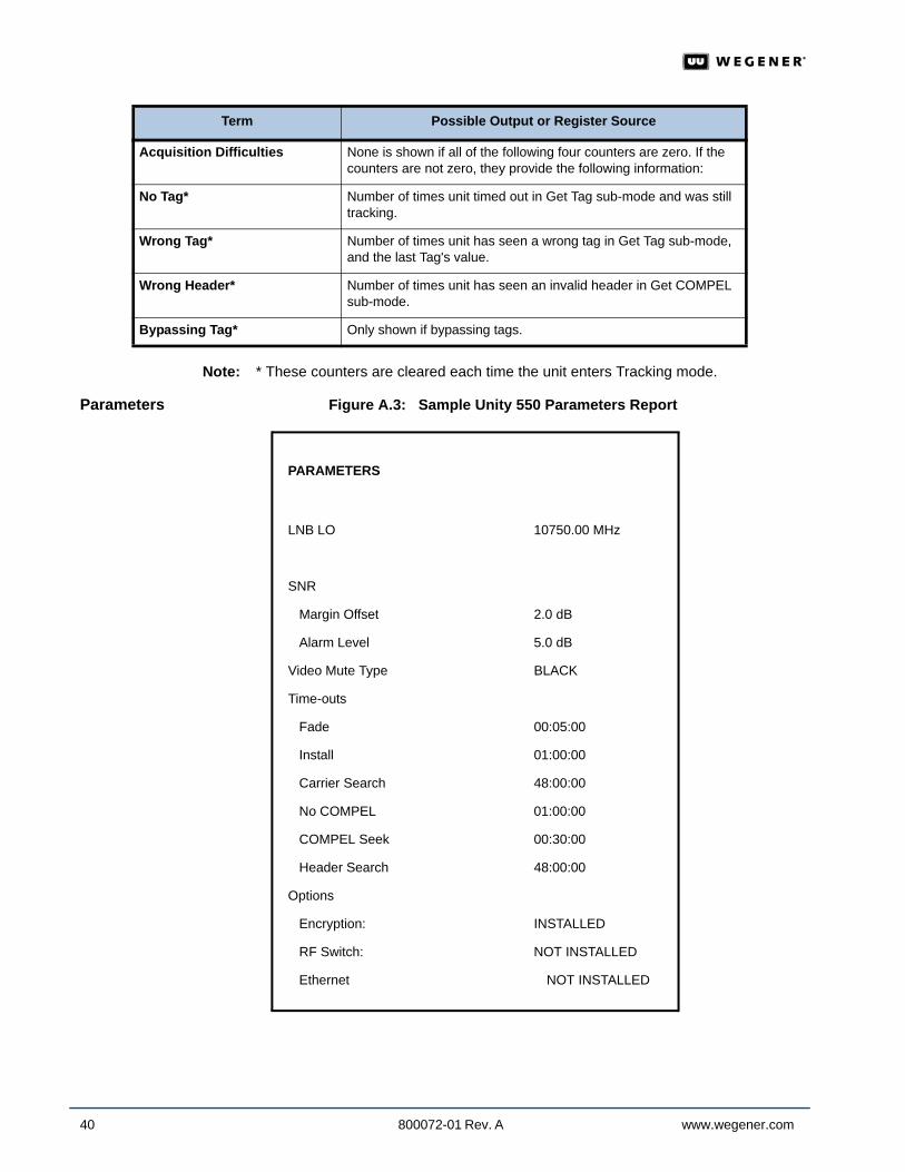
Note: * These counters are cleared each time the unit enters Tracking mode.
Parameters Figure A.3: Sample Unity 550 Parameters Report
Acquisition Difficulties None is shown if all of the following four counters are zero. If the counters are not zero, they provide the following information:
No Tag* Number of times unit timed out in Get Tag sub-mode and was still tracking.
Wrong Tag* Number of times unit has seen a wrong tag in Get Tag sub-mode, and the last Tag's value.
Wrong Header* Number of times unit has seen an invalid header in Get COMPEL sub-mode.
Bypassing Tag* Only shown if bypassing tags.
Term Possible Output or Register Source
PARAMETERS
LNB LO 10750.00 MHz
SNR
Margin Offset 2.0 dB
Alarm Level 5.0 dB
Video Mute Type BLACK
Time-outs
Fade 00:05:00
Install 01:00:00
Carrier Search 48:00:00
No COMPEL 01:00:00
COMPEL Seek 00:30:00
Header Search 48:00:00
Options
Encryption: INSTALLED
RF Switch: NOT INSTALLED
Ethernet NOT INSTALLED
www.wegener.com 800072-01 Rev. A 41
Unity 550 User’s Manual
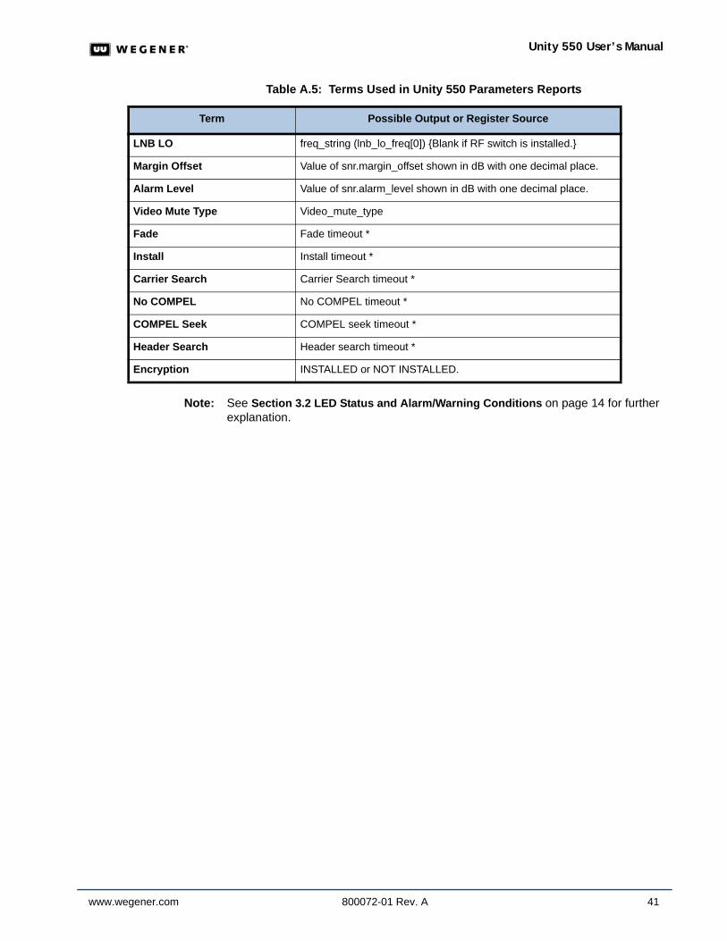
Table A.5: Terms Used in Unity 550 Parameters Reports
Note: See Section 3.2 LED Status and Alarm/Warning Conditions on page 14 for further explanation.
Term Possible Output or Register Source
LNB LO freq_string (lnb_lo_freq[0]) {Blank if RF switch is installed.}
Margin Offset Value of snr.margin_offset shown in dB with one decimal place.
Alarm Level Value of snr.alarm_level shown in dB with one decimal place.
Video Mute Type Video_mute_type
Fade Fade timeout *
Install Install timeout *
Carrier Search Carrier Search timeout *
No COMPEL No COMPEL timeout *
COMPEL Seek COMPEL seek timeout *
Header Search Header search timeout *
Encryption INSTALLED or NOT INSTALLED.
42 800072-01 Rev. A www.wegener.com
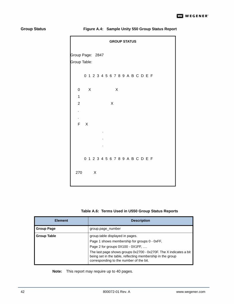
Group Status Figure A.4: Sample Unity 550 Group Status Report
Table A.6: Terms Used in U550 Group Status Reports
Note: This report may require up to 40 pages.
GROUP STATUS
Group Page: 2847
Group Table:
0 1 2 3 4 5 6 7 8 9 A B C D E F
0 X X
1
2 X
.
.
F X
.
.
.
0 1 2 3 4 5 6 7 8 9 A B C D E F
270 X
Element Description
Group Page group.page_number
Group Table group.table displayed in pages. Page 1 shows membership for groups 0 - 0xFF, Page 2 for groups 0X100 - 0X1FF, .… The last page shows groups 0x2700 - 0x270F. The X indicates a bit being set in the table, reflecting membership in the group corresponding to the number of the bit.
www.wegener.com 800072-01 Rev. A 43
Unity 550 User’s Manual
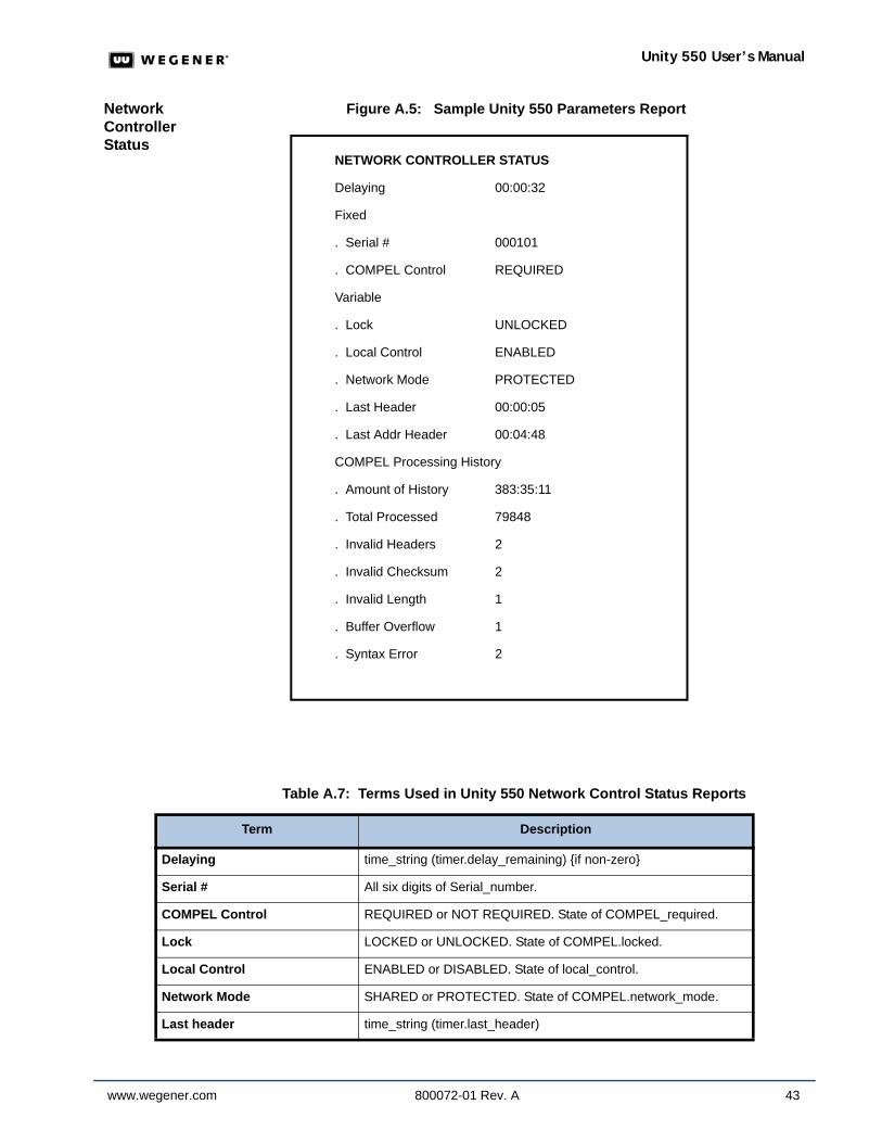
Network Controller Status
Figure A.5: Sample Unity 550 Parameters Report
Table A.7: Terms Used in Unity 550 Network Control Status Reports
NETWORK CONTROLLER STATUS
Delaying 00:00:32
Fixed
. Serial # 000101
. COMPEL Control REQUIRED
Variable
. Lock UNLOCKED
. Local Control ENABLED
. Network Mode PROTECTED
. Last Header 00:00:05
. Last Addr Header 00:04:48
COMPEL Processing History
. Amount of History 383:35:11
. Total Processed 79848
. Invalid Headers 2
. Invalid Checksum 2
. Invalid Length 1
. Buffer Overflow 1
. Syntax Error 2
Term Description
Delaying time_string (timer.delay_remaining) {if non-zero}
Serial # All six digits of Serial_number.
COMPEL Control REQUIRED or NOT REQUIRED. State of COMPEL_required.
Lock LOCKED or UNLOCKED. State of COMPEL.locked.
Local Control ENABLED or DISABLED. State of local_control.
Network Mode SHARED or PROTECTED. State of COMPEL.network_mode.
Last header time_string (timer.last_header)

44 800072-01 Rev. A www.wegener.com
MPEG Status Figure A.6: Sample Unity 550 MPEG Status Report
Last addr header time_string (timer.last_addr_header)
Amount of History time_string (timer.powered_up)
Total Processed COMPEL_stats.processed.
Invalid Headers COMPEL_stats.headers. {if non-zero and technical version}
Invalid Checksum COMPEL_stats.checksum. {if non-zero and technical version}
Invalid Length COMPEL_stats.length. {if non-zero and technical version}
Buffer Overflow COMPEL_stats.buffer. {if non-zero and technical version}
Syntax Error COMPEL_stats.syntax. {if non-zero and technical version}
Term Description
MPEG STATUS
Aggregate MPEG: Transport stream at 10.000 Mbps
Available Programs: 00001, 00002
Video
Presence: NTSC
Settings: ALARM MUTED, COMMAND MUTED
Audio Presence: A01, ENG, SPA, FRE, . . . . . ., ITA, SP2, E3
Audio Port Assignments: / Status:
Program ATTEN Routing Left Right
A01(PRI) 10 dB STEREO
ALARM/CMD MUTE ALARM MUTE
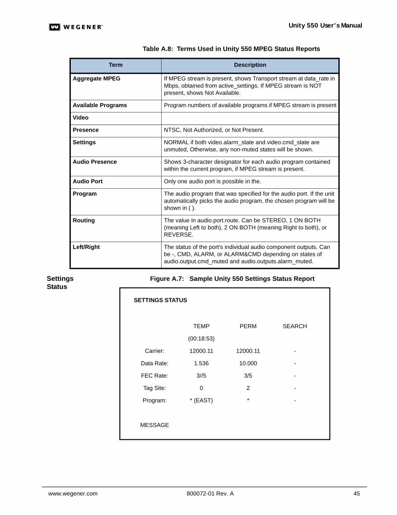
www.wegener.com 800072-01 Rev. A 45
Unity 550 User’s Manual
Table A.8: Terms Used in Unity 550 MPEG Status Reports
Settings Status
Figure A.7: Sample Unity 550 Settings Status Report
Term Description
Aggregate MPEG If MPEG stream is present, shows Transport stream at data_rate in Mbps, obtained from active_settings. If MPEG stream is NOT present, shows Not Available.
Available Programs Program numbers of available programs if MPEG stream is present
Video
Presence NTSC, Not Authorized, or Not Present.
Settings NORMAL if both video.alarm_state and video.cmd_state are unmuted, Otherwise, any non-muted states will be shown.
Audio Presence Shows 3-character designator for each audio program contained within the current program, if MPEG stream is present.
Audio Port Only one audio port is possible in the.
Program The audio program that was specified for the audio port. If the unit automatically picks the audio program, the chosen program will be shown in ( ).
Routing The value in audio.port.route. Can be STEREO, 1 ON BOTH (meaning Left to both), 2 ON BOTH (meaning Right to both), or REVERSE.
Left/Right The status of the port's individual audio component outputs. Can be -, CMD, ALARM, or ALARM&CMD depending on states of audio.output.cmd_muted and audio.outputs.alarm_muted.
SETTINGS STATUS
TEMP PERM SEARCH
(00:18:53)
Carrier: 12000.11 12000.11 -
Data Rate: 1.536 10.000 -
FEC Rate: 3//5 3/5 -
Tag Site: 0 2 -
Program: * (EAST) * -
MESSAGE
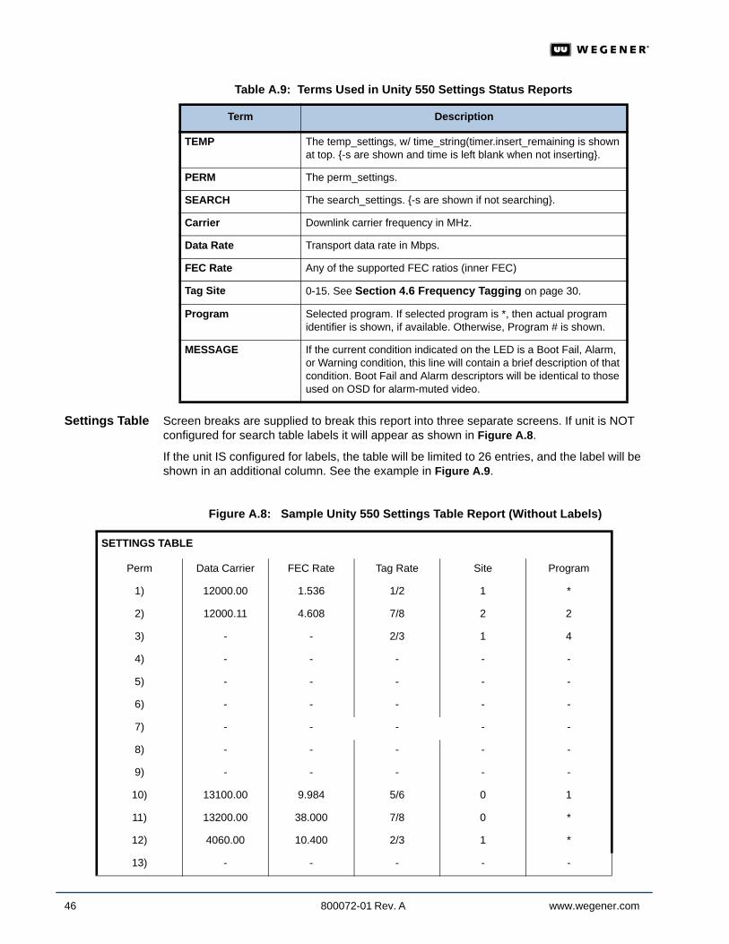
46 800072-01 Rev. A www.wegener.com
Table A.9: Terms Used in Unity 550 Settings Status Reports
Settings Table Screen breaks are supplied to break this report into three separate screens. If unit is NOT configured for search table labels it will appear as shown in Figure A.8.
If the unit IS configured for labels, the table will be limited to 26 entries, and the label will be shown in an additional column. See the example in Figure A.9.
Figure A.8: Sample Unity 550 Settings Table Report (Without Labels)
Term Description
TEMP The temp_settings, w/ time_string(timer.insert_remaining is shown at top. {-s are shown and time is left blank when not inserting}.
PERM The perm_settings.
SEARCH The search_settings. {-s are shown if not searching}.
Carrier Downlink carrier frequency in MHz.
Data Rate Transport data rate in Mbps.
FEC Rate Any of the supported FEC ratios (inner FEC)
Tag Site 0-15. See Section 4.6 Frequency Tagging on page 30.
Program Selected program. If selected program is *, then actual program identifier is shown, if available. Otherwise, Program # is shown.
MESSAGE If the current condition indicated on the LED is a Boot Fail, Alarm, or Warning condition, this line will contain a brief description of that condition. Boot Fail and Alarm descriptors will be identical to those used on OSD for alarm-muted video.
SETTINGS TABLE
Perm Data Carrier FEC Rate Tag Rate Site Program
1) 12000.00 1.536 1/2 1 *
2) 12000.11 4.608 7/8 2 2
3) - - 2/3 1 4
4) - - - - -
5) - - - - -
6) - - - - -
7) - - - - -
8) - - - - -
9) - - - - -
10) 13100.00 9.984 5/6 0 1
11) 13200.00 38.000 7/8 0 *
12) 4060.00 10.400 2/3 1 *
13) - - - - -
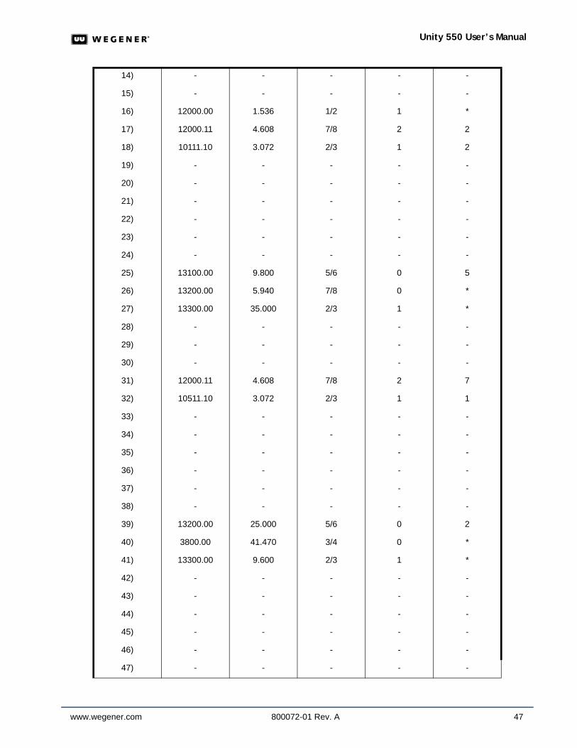
www.wegener.com 800072-01 Rev. A 47
Unity 550 User’s Manual
14) - - - - -
15) - - - - -
16) 12000.00 1.536 1/2 1 *
17) 12000.11 4.608 7/8 2 2
18) 10111.10 3.072 2/3 1 2
19) - - - - -
20) - - - - -
21) - - - - -
22) - - - - -
23) - - - - -
24) - - - - -
25) 13100.00 9.800 5/6 0 5
26) 13200.00 5.940 7/8 0 *
27) 13300.00 35.000 2/3 1 *
28) - - - - -
29) - - - - -
30) - - - - -
31) 12000.11 4.608 7/8 2 7
32) 10511.10 3.072 2/3 1 1
33) - - - - -
34) - - - - -
35) - - - - -
36) - - - - -
37) - - - - -
38) - - - - -
39) 13200.00 25.000 5/6 0 2
40) 3800.00 41.470 3/4 0 *
41) 13300.00 9.600 2/3 1 *
42) - - - - -
43) - - - - -
44) - - - - -
45) - - - - -
46) - - - - -
47) - - - - -
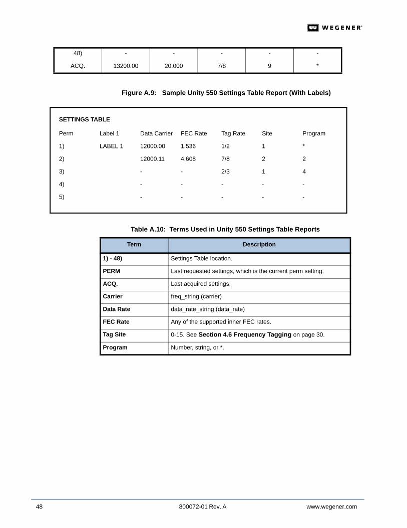
48 800072-01 Rev. A www.wegener.com
Figure A.9: Sample Unity 550 Settings Table Report (With Labels)
Table A.10: Terms Used in Unity 550 Settings Table Reports
48) - - - - -
ACQ. 13200.00 20.000 7/8 9 *
SETTINGS TABLE
Perm Label 1 Data Carrier FEC Rate Tag Rate Site Program
1) LABEL 1 12000.00 1.536 1/2 1 *
2) 12000.11 4.608 7/8 2 2
3) - - 2/3 1 4
4) - - - - -
5) - - - - -
Term Description
1) - 48) Settings Table location.
PERM Last requested settings, which is the current perm setting.
ACQ. Last acquired settings.
Carrier freq_string (carrier)
Data Rate data_rate_string (data_rate)
FEC Rate Any of the supported inner FEC rates.
Tag Site 0-15. See Section 4.6 Frequency Tagging on page 30.
Program Number, string, or *.
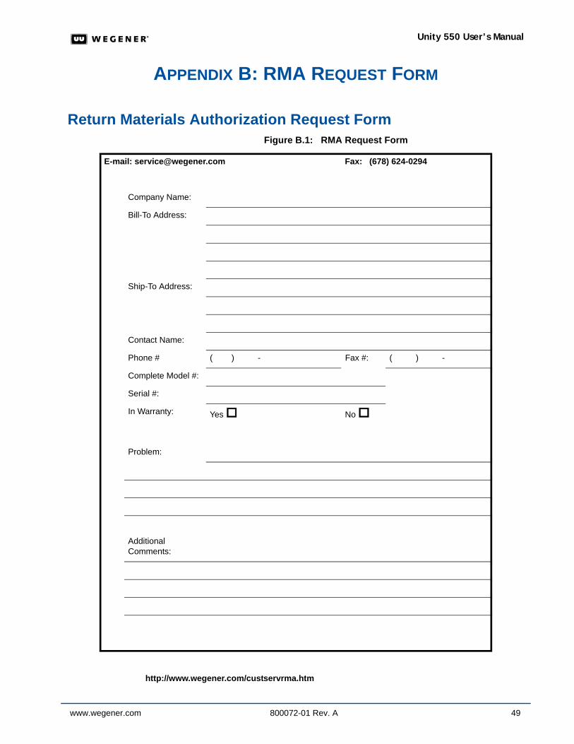
www.wegener.com 800072-01 Rev. A 49
Unity 550 User’s Manual
APPENDIX B: RMA REQUEST FORM
Return Materials Authorization Request Form Figure B.1: RMA Request Form
http://www.wegener.com/custservrma.htm
E-mail: [email protected] Fax: (678) 624-0294
Company Name:
Bill-To Address:
Ship-To Address:
Contact Name:
Phone # ( ) - Fax #: ( ) -
Complete Model #:
Serial #:
In Warranty: Yes No
Problem:
Additional Comments:

50 800072-01 Rev. A www.wegener.com

© 2006 Wegener Communications, Inc. All rights reserved.
800072-01 Rev. AFirst Edition: September 2006
Wegener Communications, Inc.Technology Park/Johns Creek
11350 Technology CircleDuluth, GA 30097-1502
Phone: 770-814-4000 Fax: 770-623-0698