Embed Size (px)
Citation preview
111111111111111111111111111111111111111111111111111111111111111111111111111US009213 668B1
(12) United States PatentWieland
(10) Patent No.:(45) Date of Patent:
US 9,213,668 Bl*Dec. 15, 2015
(54) INTERCONNECTION OF PERIPHERALDEVICES ON DIFFERENT ELECTRONICDEVICES
(56) References Cited
U.S. PATENT DOCUMENTS
(71) Applicant: Open Invention Network LLC,Durham, NC (US)
(72) Inventor: Martin Wieland, Munich (DE)
(73) Assignee: Open Invention Network, LLC,Durham, NC (US)
( *) Notice: Subject to any disclaimer, the term of thispatent is extended or adjusted under 35U.S.c. 154(b) by 0 days.
This patent is subject to a terminal disclaimer.
6,831,908 B2 * 12/2004 Kikuchi 370/3388,544,092 B2 * 9/2013 Hermann et al. 726/23
2005/0138229 Al * 6/2005 Sartore 710/15
OTHER PUBLICATIONS
Axelson, Jan; USB Complete, 3rd ed.*
* cited by examiner
Primary Examiner - Eric Oberly(74) Attorney, Agent, or Firm - Haynes and Boone, LLP
(21) Appl. No.: 14/595,489
Related U.S. Application Data
(63) Continuation of application No. 121711,440, filed onFeb. 24, 2010, now Pat. No. 8,935,434.
(51) Int. Cl.G06F 5/06 (2006.01)G06F 13/42 (2006.01)G06F 13/38 (2006.01)
(52) U.S. Cl.CPC G06F 13/423 (2013.01); G06F 5/065
(2013.01); G06F 13/385 (2013.01)(58) Field of Classification Search
CPC G06F 13/385; G06F 13/423; G06F 5/065See application file for complete search history. 18 Claims, 5 Drawing Sheets
ABSTRACT(57)
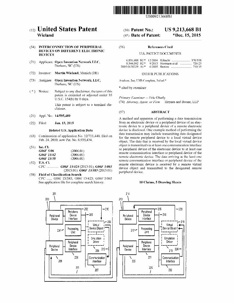
A method and apparatus of performing a data transmissionfrom an electronic device or a peripheral device of an electronic device to a peripheral device of a remote electronicdevice is disclosed. One example method of performing thedata transmission may include transmitting data designatedfor the remote peripheral device to a local virtual deviceobject. The data that is received by the local virtual deviceobject is transmitted via at least one communication interfaceor peripheral device of the electronic device to at least oneremote communication interface or peripheral device of theremote electronic device. The data arriving at the least oneremote communication interface or peripheral device of theremote electronic device is received by a remote virtualdevice object and transmitted to the designated remoteperipheral device.
Jan. 13, 2015(22) Filed:
214
213 \
\ \I 202 -210 t -215 -223Peripheral
-203Peripheral
-216Peripheral Device ~ Peripheral Device ~
Device Interface Device Interfacer······--j-205 r-- .-----j- 218I Virtual I- I Virtual 1+-
204"- Processing~
.: Device Object 1-217"- Processing
~.: Device Object!.-
Unit -.---1.---1 Unit ----.1....1
r---- ---. r-··· ..... I . I
: Emulation 1 : Emulation I
Peripheral I Driver I Peripheral 1 Driver I
Peripheral Device - -_ •••• _•••1 Peripheral Device ~_•••••••••1
Device Interface '\ 212- Device Interface '\ 224-206 219\ \
\ 208 Communication 11 \ 221 Communication 1-209 f- Interface 222 Interface
211 \ 225 \
I 207 I 220
201
200 \
u.s. Patent Dec. 15, 2015 Sheet 1 of 5 US 9,213,668 Bl
,...------+---1 MONITORSYSTEM MEMORY \
·ROM:::13i······ 130
18105-132 I................
RAM -133
OPERATINGSYSTEM -134
101
/PROCESSING
UNIT
102
/
VIDEOADAPTER
103 138
/ A /
IEEE 1394 :(INTERFACE \~'----I-"I
\104
PROGRAMDATA -137
APPLICATION A A 8 139PROGRAMS-135 A 1 r l r DEVICE /
OTHER I·~/SYSTEMBUS -105 ......---1
PROGRAM_ 136 J L ..J L l rMODULES 'J 'V V IA LOCALAREANETWORK
HARD MAGNETIC OPTICAL SERIALDISK DISK DRIVE DRIVE PORT NEnvORK
INTERFACE INTERFACE INTERFACE INTERFACE INTERFACE II\~\~~++- ~.--III ~ 114
\ \ \ \ \106 108 110 112 113
t:::I
107 109111
-
APPLICATIONPROGRAMS 1\
------.....1123
~ r;:.... ,,119 WIDE 121
U 115 ~ KE'IB(l\iIOI NE:RK V J
116/\l MODEM 1M IlEMOTEOPERATING APPliCATION OTHER"", 136 PROGRAM ~ - \ H COMPUTERSYSTEM PROGRAMS PROGRAM DATA '118 120 ..
.... 134 .... 135 MODULES ..... 137 '- 117 \
FIG.l
\ \I -202 -210 t -215 -223Peripheral
-203Peripheral
-216Peripheral'"'"
Device - Peripheral - Device -Device Interface 1
Device Interfacer---------,- 205 r--------j_ 218I Virtual I- I Virtual I +-
204'" Processing -: Device Object 1-217'" Processing ~ -: Device Object 1+-
Unit - 1 .. ----1....1-·---1---- Unitr---- ---- r---- ----: Emulation :
. I: Emulation 1
Peripheral I Driver I Peripheral 1 Driver 1
Peripheral """ Device I--"' ••••••• __1 Peripheral Device ~
ifIl._ ••••_••1, ... ,Device Interface 206 212- - Device Interface 219 224-
\ \..\ 208 Communication \ 221 Communication 1-,,.209 - Interface 222 ~ Interface
211 \ 225 \
I 207 I 220
201
200 \
FIG.2
214
213 \
~7J).•~~~
~=~
c('D
~....~Ul
No....Ul
rFJ
=('D('D.....No....Ul
drJl\CN"""'"w0-.,0'1QO
="""'"
u.s. Patent Dec. 15, 2015 Sheet 3 of 5 US 9,213,668 Bl
...------.:..-------, .".",. 300CREATE GENERIC DEVICE CLASS
..._-----......-----...... .".",. 301RECEIVE QUERYING DEVICE CLASS
"",303...------------,CREATE PRIMARY NODE
ENUMERATE NODES.".",. 302
304
/ISSUE BUS
RESET+----------_ .._--_......QUERY AVAILABLETARGET DEVICES - 305
",....,., 307 ",....,., 308--......-...,NETWORK SERIAL PORTINTERFACE INTERFACE
SET TARGET DEVICE
.".",. 309
IEEE 1394INTERFACE
.".",. 310
FIG.3
u.s. Patent Dec. 15, 2015 Sheet 4 of 5 US 9,213,668 Bl
RECEIVE DATA
",400.---....._-..,
SEND DATA" 1__
401 " r--.:-_-_-_ _....;.r-:.._-_-_--........ 1 PROTOCOL I
'" 402
QUERYTARGET DEVICE STATUS
/403
FIG.4
NO
TRANSMIT DATA
",405
BUFFER
u.s. Patent Dec. 15, 2015 Sheet 5 of 5 US 9,213,668 Bl
501
\RECEIVE DATA
~500
~502
ANALYZE DATA
.""., 504
SERIALDEVICE
BUFFER DATA
505/
IEEE 1394BUS NODE
FIG.5
506
\TRANSMIT DATA
( END)
US 9,213,668 Bl2
ronment that behaves as if it were a separate computer. Whentwo or more processes attempt to access the same device,some method of contention management must be used. Avirtual device driver allows each process to act as though ithas exclusive access to the device. For example, a virtualprinter driver would provide the printing process with a virtual printer port, and characters written to the port would bewritten to a print spooler. The virtual device driver would thensend the job to the printer when it becomes available. Another
10 method would be to assign the physical device to only oneprocess at a time, so that when a process attempts to access thedevice while it is in use, the virtual device driver does not passthe request to the actual hardware, and the process operates asthough the hardware did not exist. Virtual device drivers also
15 virtualize input/output to the device and for example a virtualnetwork device driver translates this information into commands to be sent across a network to a hardware server.
A technique that allows error free communication betweendevices that obligatory require exchange of protocol status
20 information's faster than provided by the underlying networktransport is not currently known in the art. However, such atechnique would offer significant advantages over the priorart.
A method for bridging multiple network segments and25 exposing the multiple network segments as a single network
to a higher level networking software on a bridging computing device as described in U.S. Pat. No. 7,089,335 is known inthe art. However, ifthis method is used to connect devices thatwork with a time critical protocol and the transmission speed
30 ofthe network segments fall under a certain value communication errors occur at the devices.
As disclosed in U.S. Pat. No. 6,968,307 a technique forcreation and use of virtual device drivers on a serial bus isalready known. Beside the creation of virtual device drivers
35 also an extension of the peripheral bus even over LAN andWAN networks is described. The method emulates theperipheral bus itself with all its typical features and characteristics. This method does not give an acceptable answer tothe question how devices can communicate successful if the
40 underlying network media itself does not meet the requirements of the peripheral bus in concern of speed and timing.
An extension of fast peripheral buses like the IEEE 1394"Firewire" bus over comparatively slow transport media suchas wireless networks as disclosed by the IEEE 1394 Trade
45 Association in December 2001 allows error free communication between endpoints of such an extended peripheral bus interms of bus availability and clock time synchronization.However, a solution for devices that obligatory require theexchange of protocol information's at a speed that is higher
50 than the wireless network is not included.The IEEE 1394 Trade associations white paper "Network
ing IEEE 1394 Clusters via UWB over Coaxial Cable" discloses and covers many parts of communication betweendevices on a extended peripheral bus inclusive all timing
55 requirements of video and audio devices. However, this disclosure is solely based on using an underlying network technology that is quite as fast as the peripheral bus itself. Slow,dropped out or unavailable networks are not covered by thisdisclosure.
Virtualization technologies from various manufacturersalready allow the creation of additional virtual hardwareresources such as network interface card, hard disk and computer system (Guest machine) on a physical existent computer system (Host machine). This technique emulates a
65 machine with its physical properties. By establishing interconnections between the physical devices of the host and thedevices of the emulated guest devices of the guest can be
CROSS REFERENCE TO RELATEDAPPLICATIONS
BACKGROUND OF THE INVENTION
TECHNICAL FIELD OF THE INVENTION
1INTERCONNECTION OF PERIPHERAL
DEVICES ON DIFFERENT ELECTRONICDEVICES
This application is a continuation of application Ser. No.12/711,440, entitled INTERCONNECTION OF PERIPHERAL DEVICES ON DIFFERENT ELECTRONICDEVICES, filed on Feb. 24, 2010, now issued U.S. Pat. No.8,935,434, issued on Jan. 13, 2015, the entire contents arehereby incorporated by reference.
A computer system is comprised of different componentsor devices that operate together to form the resultant system.Typical computer devices such as the central processing unitusually are supplied with the computer system initiallywhereas other devices can be installed into the computersystem after the initial configuration of the system. Thedevices of the computer system are generally coupledtogether via interconnects which may be of several types,such as system and peripheral bus.
Networks are typically comprised of a variety of differentelectronic components or devices that are able to identifY andcommunicate with each other by using an addressing andcommunication scheme that is known by each participant.The network allows computers to communicate with eachother and share resources and information. Computer networks are made up of basic hardware building blocks tointerconnect network nodes, such as Network InterfaceCards, Bridges, Hubs, Switches, and Routers. A networkcard, network adapter or NIC (network interface card) is apiece of computer hardware designed to allow computers tocommunicate over a computer network. It provides physicalaccess to a networking medium.
Device drivers are well known in the art. When a device isinstalled onto a computer by the user, a device driver has to beloaded to enable communication with the device. A devicedriver is software that is used to describe and control thedevice for the operating system. A virtual device driver is aspecific type of device driver that, like a device driver for aphysical existent device, has full access to the operating system kernel and is able to communicate directly to a physicalport. In difference to device drivers for existent hardware avirtual device driver is loaded without a hardware devicebeing detected by the system. A virtual device driver manipulates kernel mode code using existing hardware resources toemulate a device that is not present on the computer. A virtual 60
driver is given more access than a traditional device driverbecause it is not restricted to talking to just one particulardevice.
Virtual device drivers are designed to handle hardwaredevice contention between multiple processes and to translateor buffer data transfers from a virtual machine to hardwaredevices. A virtual machine is a self-contained operating envi-
The present invention relates generally to the use ofperipheral devices and communication interfaces to communicatebetween electronic devices such as computers and, in particular, to bridging ofperipheral devices via transport media thatoperates at various speeds and communication standards suchas synchronous and asynchronous.
US 9,213,668 Bl3 4
BRIEF DESCRIPTION OF THE FIGURES
FIG. 1 is a block diagram of an exemplary operating environment.
FIG. 2 is a block diagram of a system for transmission ofdata between electronic devices.
FIG. 3 is a flow chart illustrating a method of creating avirtual device in accordance with the present invention.
FIG. 4 is a flow chart illustrating a method oftransmissionof data from a peripheral device in accordance with thepresent invention.
FIG. 5 is a flow chart illustrating a method of reception ofdata by a device in accordance with the present invention.
35
virtual device object is transmitted via at least one communication interface or peripheral device ofthe electronic deviceto at least one remote commnnication interface or peripheraldevice of the remote electronic device. The method may alsoprovide that the data arriving at the at least one remote communication interface or peripheral device ofthe remote electronic device is received by a remote virtual device object andtransmitted to the designated remote peripheral device.
Another example embodiment of the present invention10 may include an apparatus configured transmit data to a
peripheral device of a remote electronic device. The apparatus may include a transmitter configured to transmit datadesignated for the remote peripheral device to a local virtualdevice object, the data received by the local virtual device
15 object is transmitted via at least one commnnication interfaceor peripheral device of the apparatus to at least one remotecommunication interface or peripheral device of the remoteelectronic device. The apparatus may also provide that thedata received at the least one remote communication interface
20 or peripheral device of the remote electronic device isreceived by a remote virtual device object and transmitted tothe designated remote peripheral device.
SUMMARY OF THE INVENTION
attached to similar physical devices of the host. However,devices on peripheral buses ofthe host machine such as nodesof a serial bus cannot be attached to nodes of the peripheralbus of the guest machine because the peripheral bus of thehost is independent ofthe guest's bus. Even ifpossible, if thearchitecture of the guest's operating system fnndamentallydiffers from the host's operating system the attachment ofnewly added devices on peripheral buses of the host to theguest's peripheral buses most likely fails because the device isannounced by the operating system and not the machine.
In Digi International's AnywhereUSB Remote I/O Concentrator documentation another method is disclosed that isapplicable for accessing physically existent USB devices onan external hardware device which is attached to a networkcable from a remote computer that is also connected to anetwork. At the remote computer a service is used that connects to the external hardware by using the TCP/IP networktransport protocol of the remote computer. Thru the networkconnection the service establishes a socket connection to thedevice. A hardware description information of each externalUSB connector is installed on the local computer. The localserial bus of the computer is extended with these new nodesand makes them part of the local serial bus. By design, thistechnique extends the local serial bus of the computer to theexternal device by emulating a wired connection over the 25
network. The external device itself gets a part of the localserial bus. This approach requires that the external devicewith it's USB connectors can be reached by the network andprovides information's about the installed connectors to thelocal service. If USB connectors are part of another comput- 30
er's local serial bus or different types of connectors are usedthis method fails because the computer does not provideinformation's about the nodes installed on his local serial busthru the network.
A peripheral device connected to a local electronic devicewhich is connected to at least one commnnication networkcan communicate with a peripheral device attached to a 40
remote electronic device as if the remote peripheral devicewas locally attached. Data designated for the remote peripheral device is received by a local virtual device object andtransmitted to the remote electronic device via at least one ofthe electronic devices communication interfaces or periph- 45
eral devices. Data received by the remote electronic device'scommnnication interface or peripheral device is written to theperipheral device at the remote electronic device by a virtualdevice object. For compensation of different transfer speedsor outages between the peripheral device and the communi- 50
cation interface or another peripheral device the virtualdevice provides the ability to utilize the virtual devices emulation driver that is attached to the virtual device object as anI/O buffer. As the invention provides a generic method forvirtualization ofa remote peripheral device it works indepen- 55
dent from specific types of devices and Operating Systems.As the invention works with synchronous and asynchronouscommnnication standards and does not require a specificnetwork transport protocol it can be used with any availablecommnnication interface or peripheral device of the elec- 60
tronic device.One embodiment of the present invention may include a
method of data transmission from an electronic device or aperipheral device of an electronic device to a peripheraldevice ofa remote electronic device. The method may include 65
transmitting data designated for the remote peripheral deviceto a local virtual device object, the data received by the local
DETAILED DESCRIPTION OF THE INVENTION
It will be readily nnderstood that the components of thepresent invention, as generally described and illustrated in thefigures herein, may be arranged and designed in a wide variety of different configurations. Thus, the following detaileddescription of the embodiments of a method, apparatus, andsystem, as represented in the attached figures, is not intendedto limit the scope of the invention as claimed, but is merelyrepresentative of selected embodiments of the invention.
The features, structures, or characteristics of the inventiondescribed throughout this specification may be combined inany suitable marmer in one or more embodiments. Forexample, the usage of the phrases "example embodiments","some embodiments", or other similar language, throughoutthis specification refers to the fact that a particular feature,structure, or characteristic described in connection with theembodiment may be included in at least one embodiment ofthe present invention. Thus, appearances of the phrases"example embodiments", "in some embodiments", "in otherembodiments", or other similar language, throughout thisspecification do not necessarily all refer to the same group ofembodiments, and the described features, structures, or characteristics may be combined in any suitable manner in one ormore embodiments.
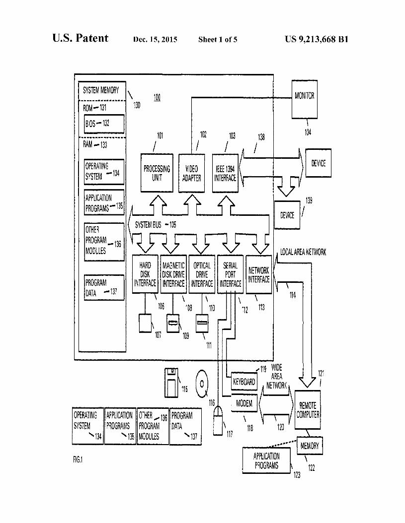
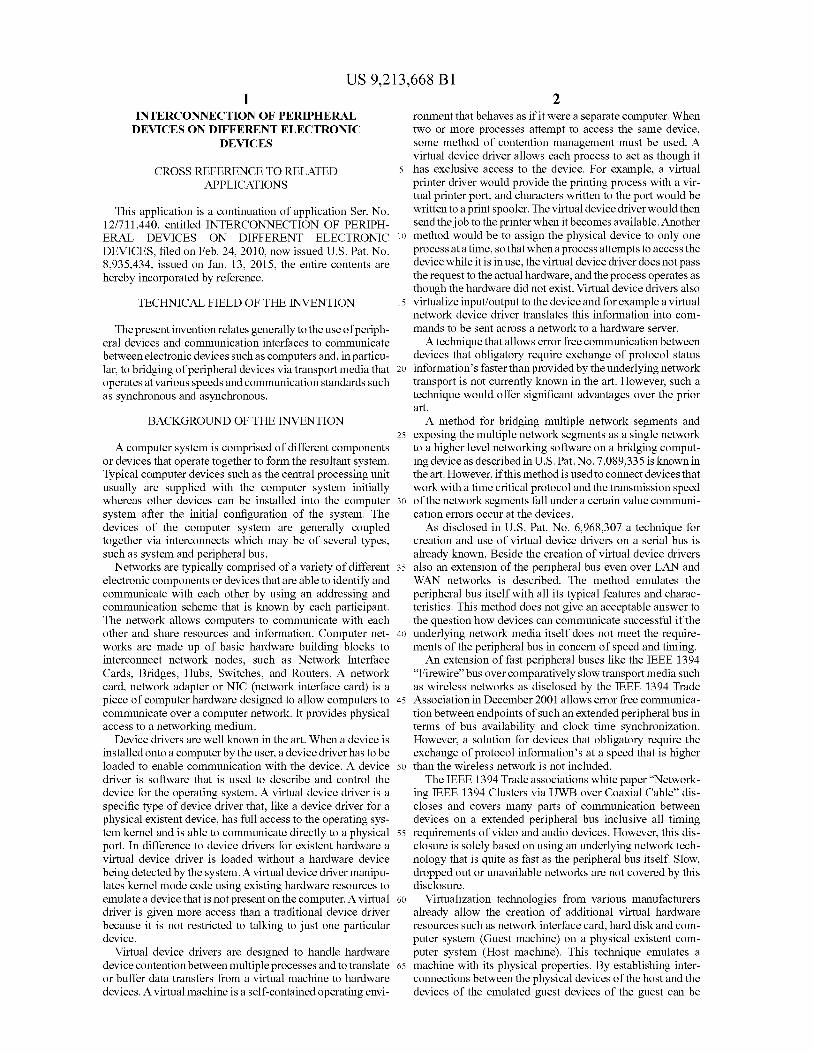
Example embodiments of the present invention may bemore vividly described with reference to FIGS. 1-5. FIG. 1 isa schematic diagram of a conventional digital electronicdevice that can be used in association with various embodiments of the present invention. The electronic device 100
US 9,213,668 Bl5
includes a processing unit 101, a system memory 130 and asystem bus 105 that couples various system componentsincluding the system memory to the processing unit. Systembus may be any of several types of bus structures including amemory bus or memory controller, a peripheral bus, and alocal bus using any of a variety of bus architectures. Systemmemory includes a read only memory (ROM) 131 and arandom access memory (RAM) 133.
A basic input/output system (BIOS) 132 containing thebasic routines that help to transfer information between ele- 10
ments within the electronic device 100, such as during startup, is stored in ROM 131. The electronic device 100 alsoincludes a hard disk drive 107 for reading from and writing toa hard disk, an optical disk drive 111 of an optical drive 15
interface 110 for reading from or writing to a removableoptical disk 116, such as a CD ROM or other optical mediaand a magnetic disk drive 109 for reading from or writing toa removable magnetic disk 115. Magnetic disk drive 109,Hard disk drive 107 and optical disk drive 111 are respec- 20
tively connected to the system bus 105 by a magnetic diskdrive interface 108, a hard disk drive interface 106 and anoptical drive interface 110. The drives and their associatedmedia provide nonvolatile storage ofelectronic devices readable instructions, data structures, program modules and other 25
data for the electronic device 100.Of course other types of media readable by electronic
devices which can store data that is accessible by an electronic device such as flash memory cards, digital video disks,magnetic cassettes, random access memories (RAMs), read 30
only memories (ROMs), and the like, may also be used in theexemplary environment.
A number of program modules can be stored on the harddisk, magnetic disk 115, optical disk 116, ROM 131 or RAM133, including an operating system 134, one or more appli- 35
cation programs 135 and 123, other program modules 136,and program data 137.
A user can enter commands and information into the electronic device 100 through input or selection devices, such asa keyboard 119 and a pointing device 117. The pointing 40
device 117 may comprise a mouse, touch pad, touch screen,voice control and activation or other similar devices.
These and other input devices are often connected to theprocessing unit 101 through a serial port interface 112 that iscoupled to the system bus, but may be connected by other 45
interfaces, such as a parallel port or a universal serial bus(USB).
A monitor 104 or other type of display device is alsoconnected to system bus 105 via an interface, such as a videoadapter 102. In addition to the monitor, electronic devices 50
typically include other peripheral output devices (not shown),such as speakers and microphones.
An additional serial port in the form of an IEEE 1394interface 103 may also be provided. The IEEE 1394 interface103 couples an IEEE 1394 compliant serial bus 138 to the 55
system bus 105 or similar communication bus. The IEEE1394 compliant serial bus 138, as known in the art, allowsmultiple devices 139 to communicate with the electronicdevice 100 and each other using high-speed serial channels.
The electronic device 100 can operate ina networked envi- 60
ronment using logical connections to one or more remoteelectronic devices, such as a remote electronic device 121. Aremote electronic device 121 typically includes at least someof the elements described above relative to the electronicdevice 100, although only a memory storage device 122 has 65
been illustrated in FIG. 1. The logical connections depicted inFIG. 1 include a local area network (LAN) 114 and a wide
6area network (WAN) 120. Such networking environments arecommonplace in offices, enterprise-wide computer networks,intranets and the Internet.
When used in a LAN networking environment, the electronic device 100 is connected to a local network 114 througha network interface or adapter 113. When used in a WANnetworking environment, local electronic device 100 andremote electronic device 121 may both include a modem 118or other means for establishing a communications over widearea network 120, such as the Internet. Modem 118, whichmay be internal or external, is connected to system bus 105via serial port interface 112.
In a networked environment, program modules depictedrelative to the electronic device 100, or portions thereof, maybe stored in the remote memory storage device. It will beappreciated that the network connections shown are exemplary and other means of establishing a communications linkbetween the electronic devices can be used. The existence ofany ofvarious well-known protocols, such as TCPIIP, "ETHERNET'" FTP, HTTP and the like, is presumed, and thesystem can be operated in a client-server configuration topermit retrieval of web pages from a web-based server. Forexample, in one example embodiment of the present invention, the remote electronic device 121 is a server havingstored thereon one or more files that may be accessed by thelocal electronic device 100. Procedures of the exampleembodiments of the present invention described below canoperate within the environment of the electronic deviceshown in FIG. 1.
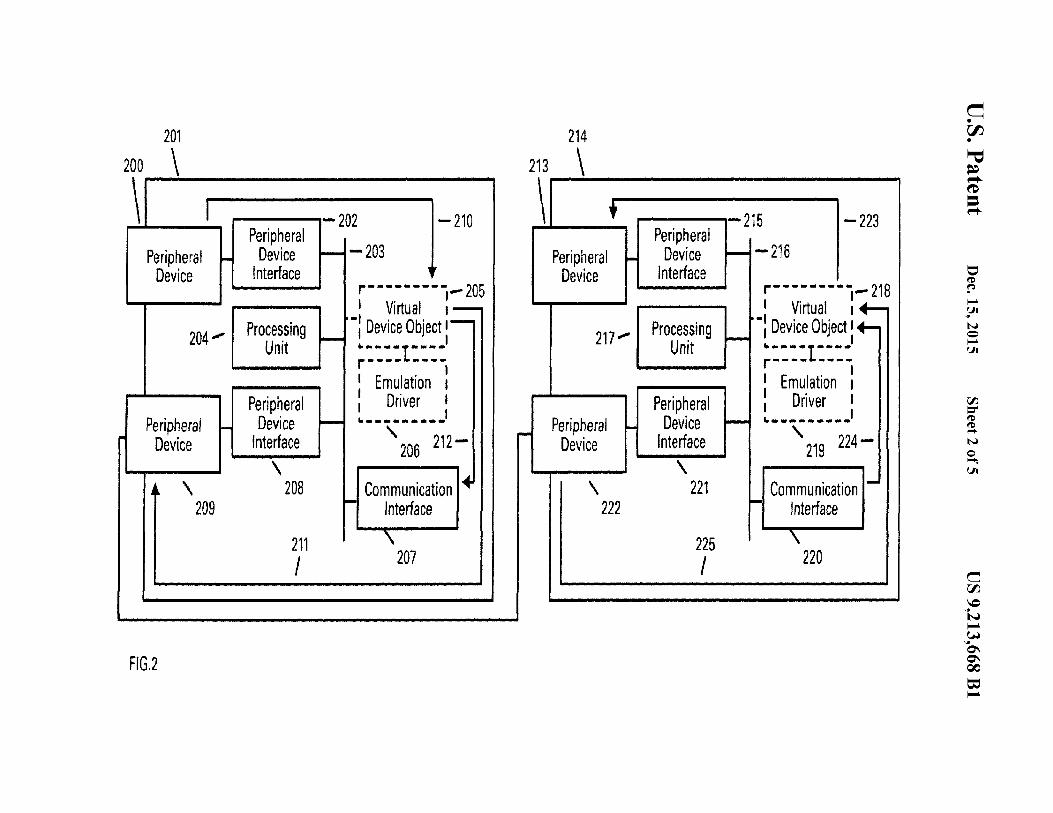
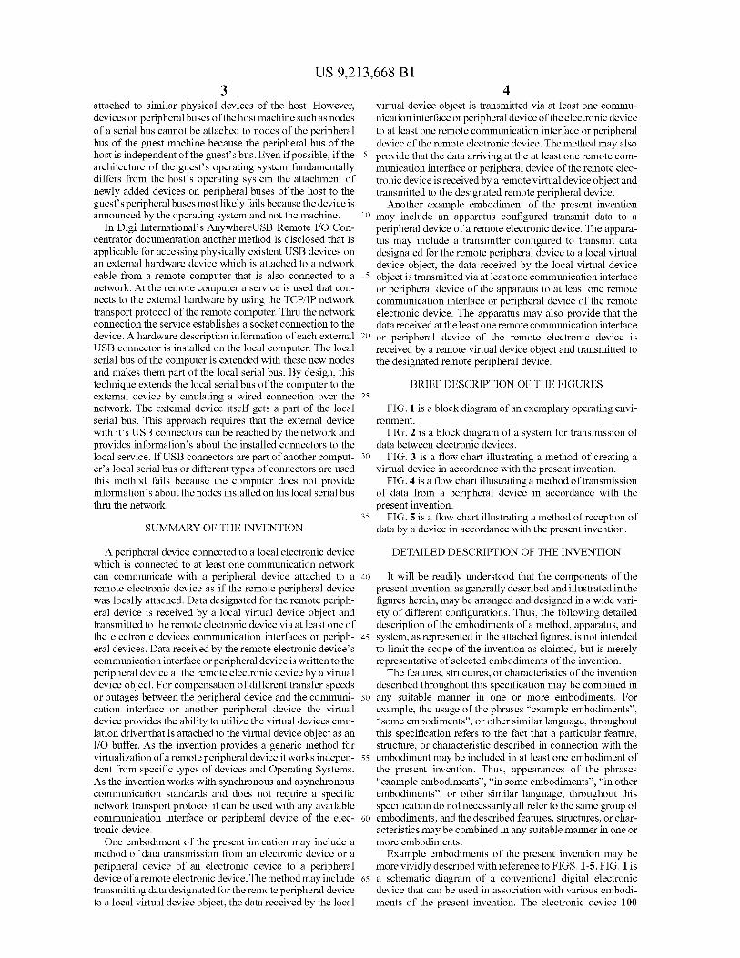
Although the example embodiments of the present invention are generally applicable to an electronic device operatingin accordance with the description shown above, the invention is applicable to any electronic device that is able touniquely identifY attached peripheral devices either by areserved memory area or a unique node id, such as, whenusing peripheral devices that are attached to a peripheralinterface that uses direct memory access control methods. InFIG. 2, there is a system that may be used in accordance withan example embodiment of the present invention. A peripheral device 200 may be connected to an electronic device 201.The electronic device 201 comprises a peripheral deviceinterface 202, which manages communications between thephysical bus 203 and the peripheral device 200. The peripheral device 200 also includes a processing unit 204 coupled toa peripheral device interface 208 connected to anotherperipheral device 209. The peripheral device 200 has a link 210 to avirtual device object 205 which has a link 212 to a communication interface 207 and another link 211 to the peripheraldevice 209.
A user of the electronic device 201 has the option of creating a virtual device object 205 that, after completing theremaining operations represents an image of the remoteperipheral device 215 plugged into the remote electronicdevice 214. At creation, the virtual device object loads anemulation driver 206 appropriate for a node of the peripheralbus ofthe selected local attached peripheral device 200. Similar to the electronic device 201, the remote device 214includes a peripheral device 213 in communication with aperipheral device interface 216 which is connected to a processing unit 217, another peripheral device interface 221 ofanother peripheral device 222. A virtual device object 218 hasa link 223 to the peripheral device and operated by an emulation driver 219. A communication interface 220 communicates via link 224 to the virtual device object 218, which hasa link 225 to the peripheral device 222.
The user may want to emulate more than one device. In thiscase, the user would repeat the process by creating a second
US 9,213,668 Bl7 8
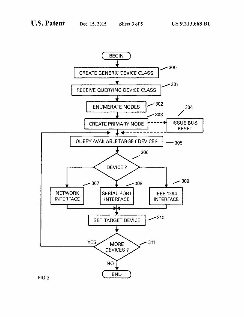
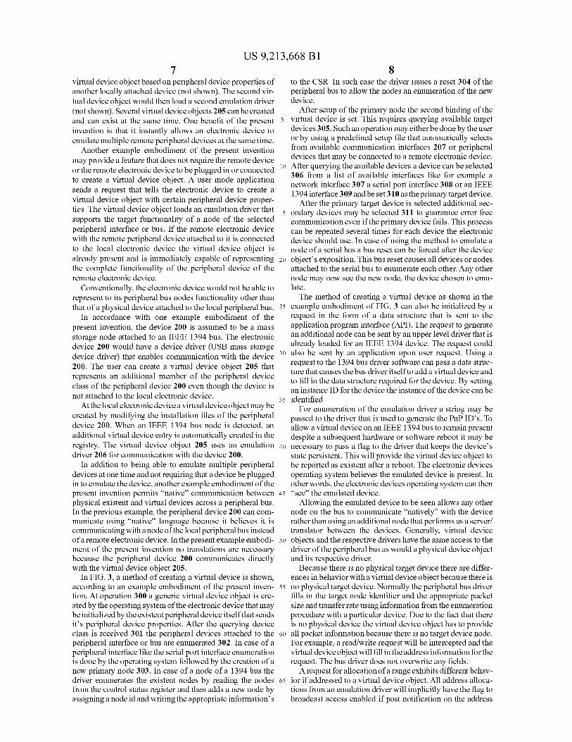
to the CSR. In such case the driver issues a reset 304 of theperipheral bus to allow the nodes an enumeration of the newdevice.
After setup of the primary node the second binding of thevirtual device is set. This requires querying available targetdevices 305. Such an operation may either be done by the useror by using a predefined setup file that automatically selectsfrom available communication interfaces 207 or peripheraldevices that may be connected to a remote electronic device.After querying the available devices a device can be selected306 from a list of available interfaces like for example anetwork interface 307 a serial port interface 308 or an IEEE1394 interface 309 and be set 310 as the primary target device.
After the primary target device is selected additional secondary devices may be selected 311 to guarantee error freecommunication even if the primary device fails. This processcan be repeated several times for each device the electronicdevice should use. In case of using the method to emulate anode of a serial bus a bus reset can be forced after the deviceobject's exposition. This bus reset causes all devices or nodesattached to the serial bus to enumerate each other. Any othernode may now see the new node, the device chosen to emulate.
The method of creating a virtual device as shown in theexample embodiment of FIG. 3 can also be initialized by arequest in the form of a data structure that is sent to theapplication program interface (API). The request to generatean additional node can be sent by an upper level driver that isalready loaded for an IEEE 1394 device. The request couldalso be sent by an application upon user request. Using arequest to the 1394 bus driver software can pass a data struc-ture that causes the bus driver itselfto add a virtual device andto fill in the data structure required for the device. By settingan instance ID for the device the instance ofthe device can be
35 identified.For enumeration of the emulation driver a string may be
passed to the driver that is used to generate the PnP ID's. Toallow a virtual device on an IEEE 1394 bus to remain presentdespite a subsequent hardware or software reboot it may benecessary to pass a flag to the driver that keeps the device'sstate persistent. This will provide the virtual device object tobe reported as existent after a reboot. The electronic devicesoperating system believes the emulated device is present. Inother words, the electronic devices operating system can then"see" the emulated device.
Allowing the emulated device to be seen allows any othernode on the bus to communicate "natively" with the devicerather than using an additional node that performs as a server!translator between the devices. Generally, virtual deviceobjects and the respective drivers have the same access to thedriver ofthe peripheral bus as would a physical device objectand its respective driver.
Because there is no physical target device there are differences in behavior with a virtual device object because there isno physical target device. Normally the peripheral bus driverfills in the target node identifier and the appropriate packetsize and transfer rate using information from the enumerationprocedure with a particular device. Due to the fact that thereis no physical device the virtual device object has to provideall packet information because there is no target device node.For example, a read/write request will be intercepted and thevirtual device object will fill in the address information for therequest. The bus driver does not overwrite any fields.
A request for allocation ofa range exhibits different behavior if addressed to a virtual device object. All address allocations from an emulation driver will implicitly have the flag tobroadcast access enabled if post notification on the address
virtual device object based on peripheral device properties ofanother locally attached device (not shown). The second virtual device object would then load a second emulation driver(not shown). Several virtual device objects 205 can be createdand can exist at the same time. One benefit of the presentinvention is that it instantly allows an electronic device toemulate multiple remote peripheral devices at the same time.
Another example embodiment of the present inventionmay provide a feature that does not require the remote deviceor the remote electronic device to be plugged in or connected 10
to create a virtual device object. A user mode applicationsends a request that tells the electronic device to create avirtual device object with certain peripheral device properties. The virtual device object loads an emulation driver that 15
supports the target functionality of a node of the selectedperipheral interface or bus. If the remote electronic devicewith the remote peripheral device attached to it is connectedto the local electronic device the virtual device object isalready present and is immediately capable of representing 20
the complete functionality of the peripheral device of theremote electronic device.
Conventionally, the electronic device would not be able torepresent to its peripheral bus nodes functionality other thanthat of a physical device attached to the local peripheral bus. 25
In accordance with one example embodiment of thepresent invention, the device 200 is assumed to be a massstorage node attached to an IEEE 1394 bus. The electronicdevice 200 would have a device driver (USB mass storagedevice driver) that enables communication with the device 30
200. The user can create a virtual device object 205 thatrepresents an additional member of the peripheral deviceclass of the peripheral device 200 even though the device isnot attached to the local electronic device.
At the local electronic device a virtual device object may becreated by modifYing the installation files of the peripheraldevice 200. When an IEEE 1394 bus node is detected, anadditional virtual device entry is automatically created in theregistry. The virtual device object 205 uses an emulation 40
driver 206 for communication with the device 200.In addition to being able to emulate multiple peripheral
devices at one time and not requiring that a device be pluggedin to emulate the device, another example embodiment ofthepresent invention permits "native" communication between 45
physical existent and virtual devices across a peripheral bus.In the previous example, the peripheral device 200 can communicate using "native" language because it believes it iscommunicating with a node ofthe local peripheral bus insteadofa remote electronic device. In the present example embodi- 50
ment of the present invention no translations are necessarybecause the peripheral device 200 communicates directlywith the virtual device object 205.
In FIG. 3, a method of creating a virtual device is shown,according to an example embodiment of the present inven- 55
tion. At operation 300 a generic virtual device object is created by the operating system ofthe electronic device that maybe initialized by the existent peripheral device itselfthat sendsit's peripheral device properties. After the querying deviceclass is received 301 the peripheral devices attached to the 60
peripheral interface or bus are enumerated 302. In case of aperipheral interface like the serial port interface enumerationis done by the operating system followed by the creation of anew primary node 303. In case of a node of a 1394 bus thedriver enumerates the existent nodes by reading the nodes 65
from the control status register and then adds a new node byassigning a node id and writing the appropriate information's
9US 9,213,668 Bl
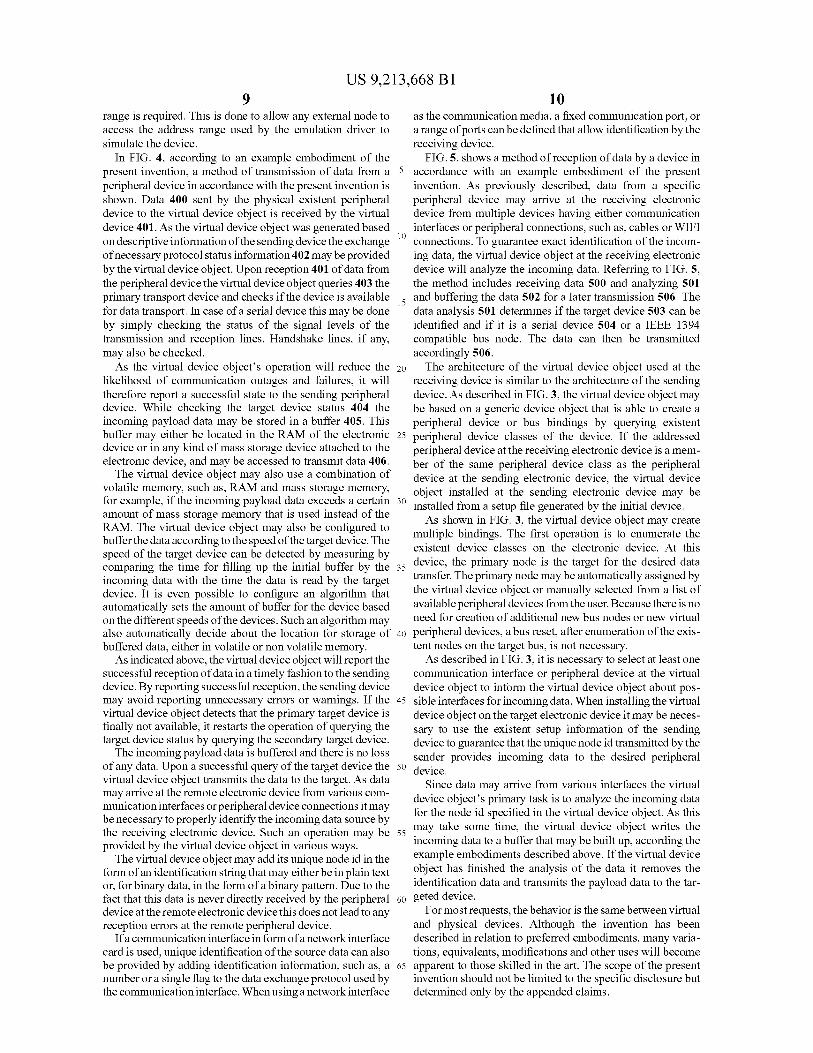
10range is required. This is done to allow any extemal node toaccess the address range used by the emulation driver tosimulate the device.
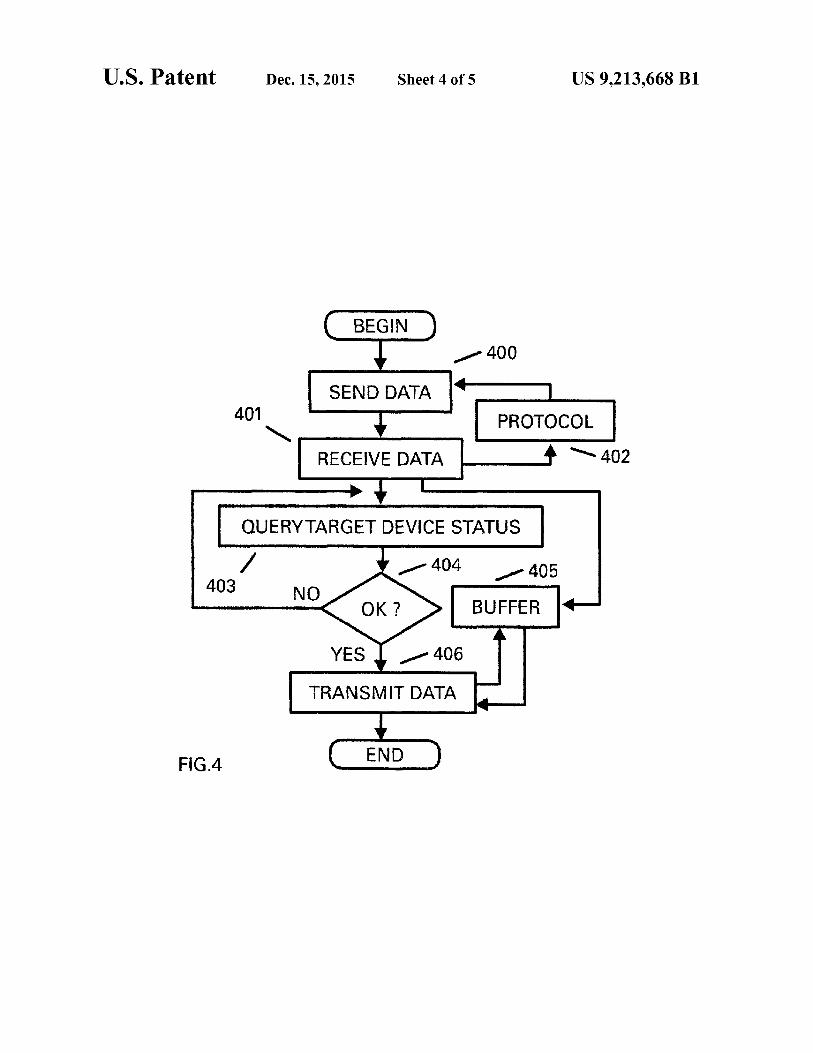
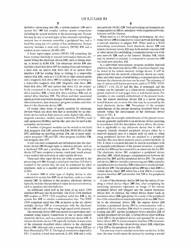
In FIG. 4, according to an example embodiment of thepresent invention, a method of transmission of data from aperipheral device in accordance with the present invention isshown. Data 400 sent by the physical existent peripheraldevice to the virtual device object is received by the virtualdevice 401. As the virtual device object was generated basedon descriptive infonnation ofthe sending device the exchange 10
ofnecessary protocol status information 402 may be providedby the virtual device object. Upon reception 401 ofdata fromthe peripheral device the virtual device object queries 403 theprimary transport device and checks if the device is available 15
for data transport. In case of a serial device this may be doneby simply checking the status of the signal levels of thetransmission and reception lines. Handshake lines, if any,may also be checked.
As the virtual device object's operation will reduce the 20
likelihood of communication outages and failures, it willtherefore report a successful state to the sending peripheraldevice. While checking the target device status 404 theincoming payload data may be stored in a buffer 405. Thisbuffer may either be located in the RAM of the electronic 25
device or in any kind of mass storage device attached to theelectronic device, and may be accessed to transmit data 406.
The virtual device object may also use a combination ofvolatile memory, such as, RAM and mass storage memory,for example, if the incoming payload data exceeds a certain 30
amount of mass storage memory that is used instead of theRAM. The virtual device object may also be configured tobuffer the data according to the speed ofthe target device. Thespeed of the target device can be detected by measuring bycomparing the time for filling up the initial buffer by the 35
incoming data with the time the data is read by the targetdevice. It is even possible to configure an algorithm thatautomatically sets the amount of buffer for the device basedon the different speeds ofthe devices. Such an algorithm mayalso automatically decide about the location for storage of 40
buffered data, either in volatile or non volatile memory.As indicated above, the virtual device object will report the
successful reception ofdata in a timely fashion to the sendingdevice. By reporting successful reception, the sending devicemay avoid reporting unnecessary errors or wamings. If the 45
virtual device object detects that the primary target device isfinally not available, it restarts the operation of querying thetarget device status by querying the secondary target device.
The incoming payload data is buffered and there is no lossof any data. Upon a successful query of the target device the 50
virtual device object transmits the data to the target. As datamay arrive at the remote electronic device from various communication interfaces or peripheral device connections it maybe necessary to properly identifY the incoming data source bythe receiving electronic device. Such an operation may be 55
provided by the virtual device object in various ways.The virtual device object may add its unique node id in the
form ofan identification string that may either be in plain textor, for binary data, in the form of a binary pattem. Due to thefact that this data is never directly received by the peripheral 60
device at the remote electronic device this does not lead to anyreception errors at the remote peripheral device.
Ifa communication interface in form ofa network interfacecard is used, unique identification ofthe source data can alsobe provided by adding identification information, such as, a 65
number or a single flag to the data exchange protocol used bythe communication interface. When using a network interface
as the communication media, a fixed communication port, ora range ofports can be defined that allow identification by thereceiving device.
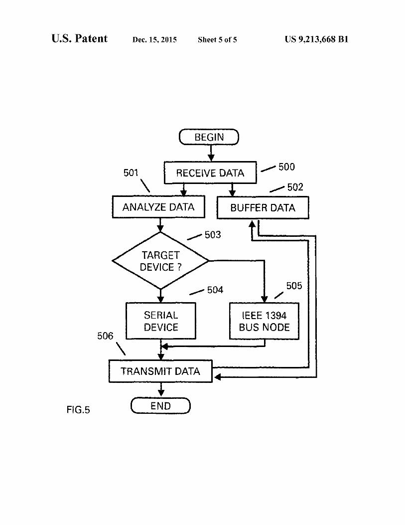
FIG. 5. shows a method of reception ofdata by a device inaccordance with an example embodiment of the presentinvention. As previously described, data from a specificperipheral device may arrive at the receiving electronicdevice from multiple devices having either communicationinterfaces or peripheral connections, such as, cables or WIFIconnections. To guarantee exact identification of the incoming data, the virtual device object at the receiving electronicdevice will analyze the incoming data. Referring to FIG. 5,the method includes receiving data 500 and analyzing 501and buffering the data 502 for a later transmission 506. Thedata analysis 501 detennines if the target device 503 can beidentified and if it is a serial device 504 or a IEEE 1394compatible bus node. The data can then be transmittedaccordingly 506.
The architecture of the virtual device object used at thereceiving device is similar to the architecture of the sendingdevice. As described in FIG. 3, the virtual device object maybe based on a generic device object that is able to create aperipheral device or bus bindings by querying existentperipheral device classes of the device. If the addressedperipheral device at the receiving electronic device is a member of the same peripheral device class as the peripheraldevice at the sending electronic device, the virtual deviceobject installed at the sending electronic device may beinstalled from a setup file generated by the initial device.
As shown in FIG. 3, the virtual device object may createmultiple bindings. The first operation is to enumerate theexistent device classes on the electronic device. At thisdevice, the primary node is the target for the desired datatransfer. The primary node may be automatically assigned bythe virtual device object or manually selected from a list ofavailable peripheral devices from the user. Because there is noneed for creation of additional new bus nodes or new virtualperipheral devices, a bus reset, after enumeration ofthe existent nodes on the target bus, is not necessary.
As described in FIG. 3, it is necessary to select at least onecommunication interface or peripheral device at the virtualdevice object to infonn the virtual device object about possible interfaces for incoming data. When installing the virtualdevice object on the target electronic device it may be necessary to use the existent setup infonnation of the sendingdevice to guarantee that the unique node id transmitted by thesender provides incoming data to the desired peripheraldevice.
Since data may arrive from various interfaces the virtualdevice object's primary task is to analyze the incoming datafor the node id specified in the virtual device object. As thismay take some time, the virtual device object writes theincoming data to a buffer that may be built up, according theexample embodiments described above. If the virtual deviceobject has finished the analysis of the data it removes theidentification data and transmits the payload data to the targeted device.
For most requests, the behavior is the same between virtualand physical devices. Although the invention has beendescribed in relation to preferred embodiments, many variations, equivalents, modifications and other uses will becomeapparent to those skilled in the art. The scope of the presentinvention should not be limited to the specific disclosure butdetermined only by the appended claims.
US 9,213,668 Bl11 12
25
55
interface and peripheral device of the apparatus to atleast one of a remote communication interface and theremote peripheral device of the remote electronicdevice;
a buffer configured to buffer the data at the local virtualdevice object, which transmits a report message indicating the successful reception of the data at the local virtual device object, and wherein a buffer size ofthe bufferdynamically adjusts according to a transfer speed oftheperipheral device that transmits the data;
wherein the transmitter transmits a query to the remoteperipheral device via the local virtual device object todetermine the remote peripheral device is available toreceive data; and
wherein the data, including source identification information, is transmitted to the at least one of the remotecommunication interface and the remote peripheraldevice ofthe remote electronic device, and is received bya remote virtual device object which transmits the data tothe designated remote peripheral device.
10. The apparatus of claim 9, wherein the designatedremote peripheral device is identified by payload datareceived.
11. The apparatus of claim 9, wherein the designatedremote peripheral device is identified by a content of a communication protocol of the communication interface.
12. The apparatus of claim 9, wherein at least one communication interface or peripheral device of the apparatus uses
30 an asynchronous communication standard.13. The apparatus of claim 9, wherein at least one commu
nication interface or peripheral device ofthe apparatus uses asynchronous communication standard.
14. The apparatus ofclaim 9, wherein the peripheral device35 of the apparatus is connected to a peripheral bus.
15. The apparatus ofclaim 9 comprising a receiver configured to receive a request to create a local virtual device objectcomprising properties of the remote peripheral device,wherein the receiver receives a query response indicating the
40 query was successful.16. The apparatus of claim 9, wherein the buffer size
dynamically increases or decreases according to the transferspeed ofthe communication interface or the peripheral deviceused for data transmission by the apparatus.
17. A non-transitory computer readable storage mediumconfigured to store a computer program that when executedby a processor performs data transmission from an electronicdevice or a peripheral device of an electronic device to aremote peripheral device of a remote electronic device, the
50 processor being further configured to perform:creating a local virtual device object comprising properties
of the remote peripheral device by an operating systemof the electronic device, the local virtual device objectoperating on the electronic device and emulating theremote peripheral device of the remote electronicdevice;
transmitting data designated for the remote peripheraldevice to the local virtual device object, the data receivedby the local virtual device object is transmitted via atleast one of a communication interface and the peripheral device of the electronic device to at least one of aremote communication interface and the remote peripheral device of the remote electronic device;
buffering the data at a buffer at the local virtual deviceobject and wherein a buffer size of the buffer dynamically adjusts according to a transfer speed ofthe peripheral device that transmits the data;
What is claimed is:1. A method ofdata transmission from an electronic device
or a peripheral device of an electronic device to a remoteperipheral device of a remote electronic device, the methodcomprising:
creating a local virtual device object comprising propertiesof the remote peripheral device by an operating systemof the electronic device, the local virtual device objectoperating on the electronic device and emulating theremote peripheral device of the remote electronic 10
device;transmitting data designated for the remote peripheral
device to the local virtual device object, the data receivedby the local virtual device object is transmitted via atleast one of a communication interface and a peripheral 15
device ofthe electronic device to at least one ofa remotecommunication interface and the remote peripheraldevice of the remote electronic device;
buffering the data at a buffer at the local virtual deviceobject and wherein a buffer size of the buffer dynami- 20
cally adjusts according to a transfer speed ofthe peripheral device that transmits the data;
transmitting a report message from the local virtual deviceobject to the electronic device indicating the successfulreception of data at the local virtual device object;
receiving by a remote virtual device object the data designated for the at least one of the remote communicationinterface and the peripheral device of the remote electronic device, wherein the received data includes sourceidentification information;
querying the remote peripheral device via the local virtualdevice object to determine the remote peripheral deviceis available to receive data; and
transmitting the data to the designated remote peripheraldevice.
2. The method of claim 1, wherein the designated remoteperipheral device is identified by payload data received.
3. The method of claim 1, wherein the designated remoteperipheral device is identified by a content of a communication protocol of the communication interface.
4. The method of claim 1, wherein at least one communication interface or peripheral device of the electronic deviceuses an asynchronous communication standard.
5. The method of claim 1, wherein at least one communication interface or peripheral device of the electronic device 45
uses a synchronous communication standard.6. The method ofclaim 1, wherein the peripheral device of
the electronic device is counected to a peripheral bus.7. The method ofclaim 1, comprising receiving a request at
the electronic device to create the local virtual device objectcomprising properties of the remote peripheral device.
8. The method of claim 1, wherein the buffer size dynamically increases or decreases according to the transfer speed ofthe communication interface or the peripheral device used fordata transmission by the electronic device.
9. An apparatus configured to transmit data to a remoteperipheral device ofa remote electronic device, the apparatuscomprising:
a processor configured to create a local virtual deviceobject utilizing an operating system, the local virtual 60
device object operating on the electronic device andused to emulate the remote peripheral device of theremote electronic device;
a transmitter configured to transmit data designated for theremote peripheral device to the local virtual device 65
object, the data received by the local virtual deviceobject is transmitted via at least one ofa communication
US 9,213,668 Bl13
transmitting a report message from the local virtual deviceobject to the electronic device indicating the successfulreception of data at the local virtual device object;
receiving by a remote virtual device object the data designated from the at least one ofthe remote communicationinterface and the peripheral device of the remote electronic device, wherein the received data includes sourceidentification information;
querying the remote peripheral device via the local virtualdevice object to determine the remote peripheral device 10
is available to receive data; andtransmitting the data to the designated remote peripheral
device.18. The non-transitory computer readable storage medium
ofclaim 17, wherein the buffer size dynamically increases or 15
decreases according to the transfer speed of the communication interface or the peripheral device used for data transmission by the electronic device.
* * * * *
14