Embed Size (px)
Citation preview
(12) United States Patent Schultz
ACTIVE MULTISTABLE TWISTING DEVICE
Inventor: Marc R. Schultz, Louisville, CO (US)
Assignee: United States of America as represented by the Administrator of the National Aeronautics and Space Administration, Washington, DC (US)
Subject to any disclaimer, the term of this patent is extended or adjusted under 35 U.S.C. 154(b) by 171 days.
Notice:
Appl. No.: 11/370,377
Filed: Mar. 6, 2006
Prior Publication Data
US 200710120011 A1 May 31, 2007
Related U.S. Application Data
Provisional application No. 601660,025, filed on Mar. 4. 2005.
Int. C1. HOlL 41/08 (2006.01) HOlL 41/12 (2006.01) H02N 2/00 (2006.01) H02N 1 O/OO (2006.01) U.S. C1. ...................... 310/368; 3101328; 3101330;
3101371; 310126; 3101307; 3101309 Field of Classification Search ................ 3101324,
3101328,330-332,368,371 See application file for complete search history.
References Cited
U.S. PATENT DOCUMENTS
3,816,774 A * 6/1974 Ohnuki et al. .............. 310/332
/-*
(io) Patent No.: (45) Date of Patent:
US 7,321,185 B2 Jan. 22,2008
4,099,211 A 7/1978 Hathaway 4,383,195 A * 5/1983 Kolm et al. ................ 310/330 4,672,257 A * 6/1987 Oota et al. .................. 310/328 4,915,017 A * 4/1990 Perlov ......................... 92/5 R 5,241,235 A 8/1993 Culp 5,303,105 A 4/1994 Jorgenson 5,315,204 A * 5/1994 Park ........................... 310/339 5,374,011 A 12/1994 Lazams et al. 5,628,411 A * 5/1997 Mills et al. ................. 209/644 5,861,702 A * 1/1999 Bishop et al. .............. 310/330 5,973,441 A 10/1999 Lo et al. 6,392,331 B1 * 5/2002 Sciacca et al. .............. 310/348 6,545,395 B2 * 4/2003 Matsui et al. ............... 310/369
(Continued)
FOREIGN PATENT DOCUMENTS
wo WO-02-25057 * 3/2002
OTHER PUBLICATIONS
Hyer, M.W., “Some Observations on the Cured Shape of Thin Unsymmetric Laminates”, Journal of Composite Materials, 1981, p. 175 - 194.
(Continued)
Primary Examiner-Thomas M. Dougherty (74) Attorney, Agent, or Firm-Robin W. Edwards
(57) ABSTRACT
Two similarly shaped, such as rectangular, shells are attached to one another such that they form a resulting thin airfoil-like structure. The resulting device has at least two stable equilibrium shapes. The device can be transformed from one shape to another with a snap-through action. One or more actuators can be used to effect the snap-through; i.e., transform the device from one stable shape to another. Power to the actuators is needed only to transform the device from one shape to another.
27 Claims, 6 Drawing Sheets
r4
https://ntrs.nasa.gov/search.jsp?R=20080018816 2018-07-25T01:09:00+00:00Z
US 7,321,185 B2 Page 2
~
U.S. PATENT DOCUMENTS
6,847,155 B2* 1/2005 Schwartz et al. ........... 310/328 6,979,937 B2 * 12/2005 Masters et al. ............. 310/332
2001/0043027 A1 * 11/2001 Hellbaum et al. .......... 310/330 2003/0029705 A1 * 2/2003 Qiu et al. ................... 200/181 2004/0004532 A1 * 1/2004 Davis et al. .................. 337/53 2004/0050674 A1 3/2004 Rube1 2005/0023933 A1 2/2005 Magnussen et al. 2006/0038643 A1 * 2/2006 Xu et al. ...................... 335/78
OTHER PUBLICATIONS
Hyer, M.W., “Calculations of the Room-Temperature Shapes of Unsymmetric Laminates,” Journal of Composite Materials, 1981, p. 296-310. Dano, M.L. and Hyer, M.W., “Thermally-Induced Deformation Behavior of Unsymmetric Laminates,” International Journal of Solids and Stmctures, 1998, vol. 35 ( No. 17), p. 2101-2120. Hufenbach, W. Gude, M., and Kroll, L., “Design of Multistable Composites for Application in Adaptive Stmctures,” Composites Science and Technology, vol. 62 ( No. 16), p. 2201-2207, no date given. Luo, J. J. and Daniel, I.M., “Thermally-Induced Deformation of Asymmetric Composite Laminates,” Proceedings of the 18th Annual Technical Conference of the American Society for Com- posites, 2003, p. 128-136. Cho, M., Kim, M.H., Choi, H.S., Chung, H.C., Ahn, K.J., and Eom, Y.S., “A Study on the Room-Temperature Curvature Shapes of Unsymmetric Laminates Including Slippage Effects,” 1998, vol. 32 ( N o . 5). Ren. L, Parvizi-Majidi, A. and Li. Z, “Cured Shape of Cross-Ply Composite Thin Shells,” Journal of Composite Materials, 2003, vol. 37 ( No. 20), p. 1801-1820. Schultz, M.S. and Hyer, M.W., “A Morphing Concept Based on Unsymmetric Composite Laminates and Piezoceramic MFC Actua- tors,’’ Proceedings of the 45th AIAA/ASME/ASCE/AHS/ASC Stmctures, no date given.
Schultz, M.R. and Hyer, M.W., “Snap-Through of Unsymmetric Cross-Ply Laminates Using Piezoceramic Actuators,” Journal of Intelligent Material Systems and Stmctures, vol. 14 ( No. 12), p. 795-814, no date given. Dano, M.L. and Hyer, M.W., “Snap-Through of Unsymmetric Fiber-Reinforced Composite Laminates,” International Journal of Solids and Stmctures, p. 175-198, no date given. Murphey, T.W. and Pellegrino S., “A Novel Actuated Composite Tape-Spring for Deployable Stmctures,” Proceedings of the 45th AIAA/ASME/ASCE/AHS/ASC Structures, no date given. Iqbal, K. and Pellegrino, S., “Bi-Stable Composite Shells,” Pro- ceedings of the 4 1st AIAA/ASME/ASCE/AHS/ASC Stmctures, no date given. Galletly, D.A. and Guest, S.D., “Bistable Composite Slit Tubes. 11. A Shell Model,” International Journal of Solids , p. 4503-4516, no date given. Santer, M. J. and Pellegrino, S., “An Asymmetrically-Bistable Monolithic Energy-Storing Stmcture,” Proceedings of the 45th AIAA/ASME/ASCE/AHS/ASC Structures, no date given. Schioler, T. and Pellegrino, S., “Multi-Configuration Space Frames,” Proceedings of the 45th AIAA/ASME/ASCE/AHS/ASC Stmctures, no date given. Seffen, K.A., “Bi-Stable Concepts for Reconfigurable Stmctures,” Proceedings of the 45th AIAA/ASME/ASCE/AHS/ASC Stmctures, no date given. Kebadze, E., Guest, S.D., and Pellegrino, S., “Bistable Prestressed Shell Stmctures,” International Journal of Solids and Stmctures, p. 2801-2820, no date given. Wilson, J.R., “Active Aeroelastic Wing: A New/Old Twist on Flight,” Aerospace America, vol. 43 ( No. l), p. 27-30, no date given. Phillips, W.F., “New Twist on an old Wing Theory,” Aerospace America, vol. 40 ( No. 9), p. 34-37, no date given.
* cited by examiner
U.S. Patent Jan. 22,2008 Sheet 1 of 6
/-*
US 7,321,185 B2
/"
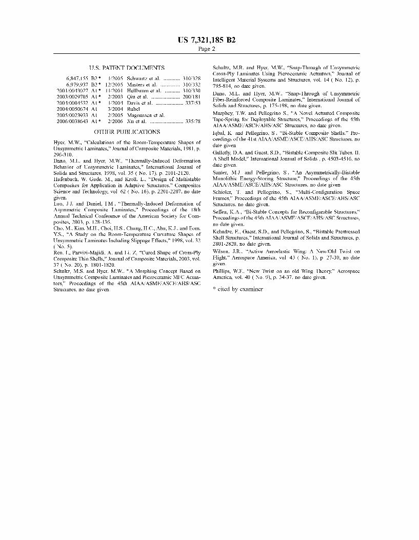
FIG. 1
U.S. Patent Jan. 22,2008 Sheet 2 of 6 US 7,321,185 B2
22
FIG. 2A
22
Z
‘X
FIG. 2B
22
v> 43 0 rc,
10 1 I 12 13 14
c, a2 a2 E m
5 I 16
c7
Qo 0 0 e4
cu M
U.S. Patent Jan. 22,2008 Sheet 4 of 6 US 7,321,185 B2
FIG. 4A
ky X
FIG. 4B
U.S. Patent Jan. 22,2008 Sheet 5 of 6
2.0 1 .B
0.2 n o . , . , . , . , . , - , - ,
OB 09 10 1.1 12 13 1 1 15
Normalized Curvature
FIG. 5A
FIG. 5C
US 7,321,185 B2
2.0 - 1.8 - 1.6
2 1.4
TI a 1.0 N 3 0.8
0.6 Z 0.4
a)
9 1.2
.-
0
0.2 0.0
- -0'
i ~ l l l ' ' 1 ' 1 ' 1 ' 1 ' 1 0.6 0.7 08 09 1.0 1.1 12 13 1.4
Normalized Thickness
FIG. 5B
Normalized Tip Angle
FIG. 5D
U.S. Patent Jan. 22,2008
2.0 - I
Normalized Curvature
FIG. 6A
Root-End Spacing (mm)
FIG. 6C
Sheet 6 of 6 US 7,321,185 B2
o . o : ’ , ’ , ’ , ’ r . l ’ l ’ l ‘ i 0.6 0.7 0.8 09 1.0 1.1 12 13 1A
Normalized Thickness
1.2 2 1.0 ; 0.8 f 0.6 3 0.4
0 z 0.0
.-
s 0.2
FIG. 6B
c. C
E 0 2.0 -
1 7 1 ’ 1 ‘ I
0.6 0.7 04 09 1.0 1.1 12 13 1.4 15 Normalized Tip Angle
FIG. 6D
US 7,321,185 B2 1 2
ACTIVE MULTISTABLE TWISTING DEVICE BRIEF DESCRIPTION OF THE DRAWINGS
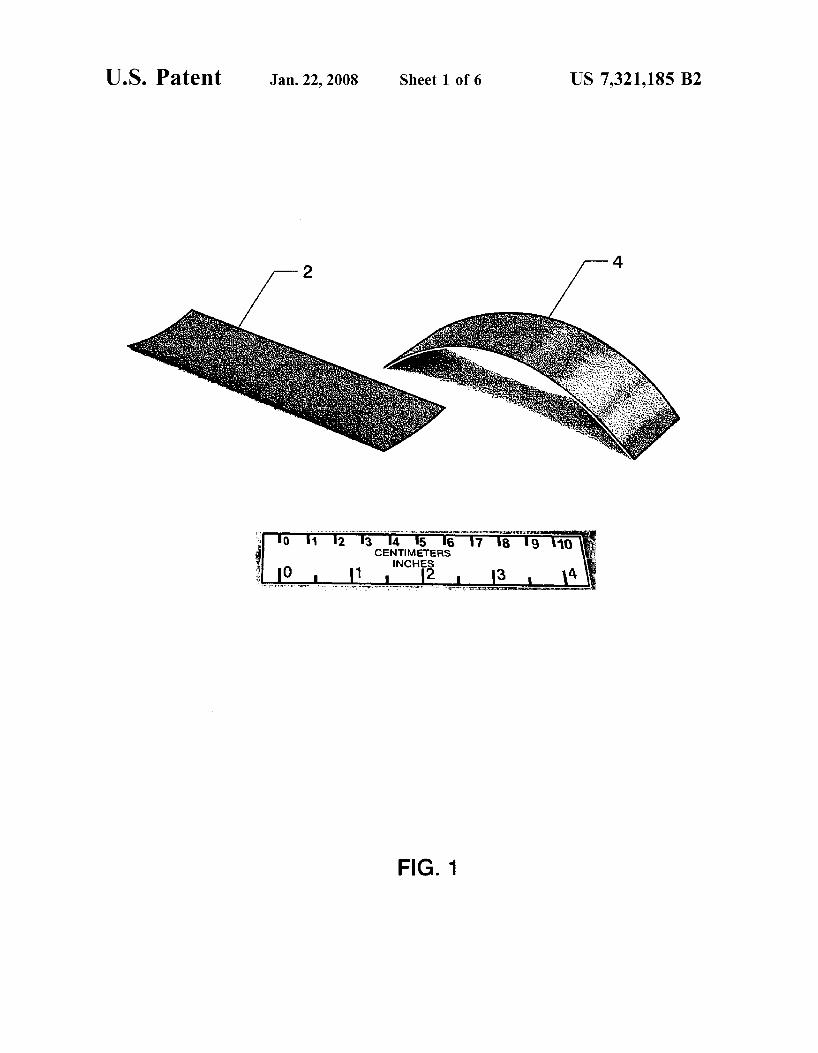
FIG. 1 shows two stable cylindrical constituent shells; FIGS. 2A and 2B are analvtical remesentations of a
ORIGIN OF THE INVENTION
The invention described herein may be manufactured and 5 multistable device comprised of two constituent thin com-
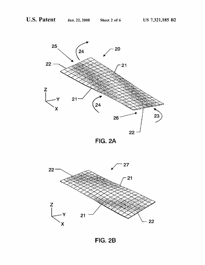
FIG. 3 illustrates the placement of actuators on constitu-
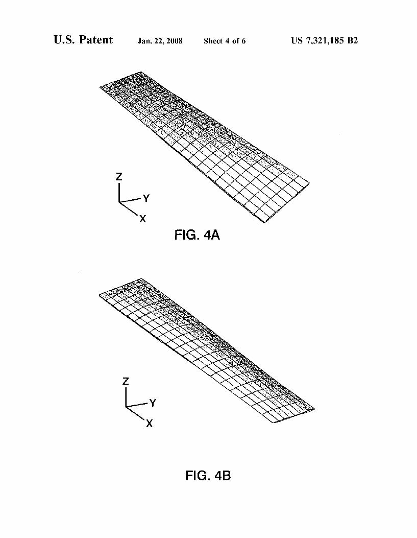
FIGS, 4A and 4B are analytical representations of a
used by or for the Government of the United States of America for governmental purposes without the payment of any royalties thereon or therefor. Pursuant to 35 U.S.C.
601660,025, with a filing date of Mar. 4,2005, is claimed for this non-provisional application.
posite
ent shells;
9 9, the benefit Of priority from Provisional 10 multistable device comprised of two thin steel shells;
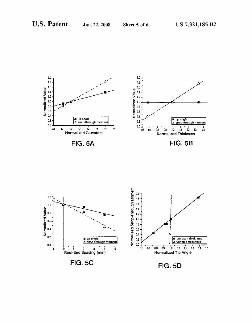
exemplary composite multistable device; and FIGS. 5A, 5B, 5C and 5D show analytical results for an
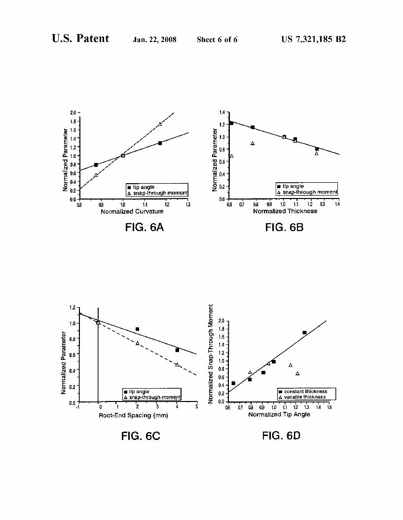
FIGS. 6A, 6B, 6C and 6D show analytical results for an BACKGROUND OF THE INVENTION 15 exemplary steel multistable device.
DETAILED DESCRIPTION OF THE INVENTION
1. Field of the Invention This invention relates to multistable structures. More
specifically, the invention is an active multistable device that can produce a change in twist when actuated.
20 In one embodiment of the present invention, two similar- shape, such as rectangular, unsymmetric composite lami- 2. Description of the Related Art
Many articulating and morphing structures use multiple nates, each having two stable cylindrical shapes, such as the Parts and Often use complicated actuation n~chanisms such shapes 2 and 4 shown in FIG. 1, are attached to one another as hydraulic actuators, screws, Or Other devices to Provide such that they form a multistable clamshell-type structure geometric change in the Structure through the use of hinges, 25 having two stable shapes, such as 20 and 27 illustrated in telescoping sections, and othermechanisms. For example, in FIGS. 2A and 2B. The laminates are aligned so that they are many fixed wing aircraft, the wings Provide stable lift, while convex outward, touching along the long edges 21, and the hYdraulicallY-oPerated flaps change lift and drag, and con- structure is open along the short edges 22. As the short edges trol is accomplished by moving the rudder and ailerons, are pressed together, twist curvature develops along the long which are also hydraulically operated. 30 axis x, while the overall convexity of the structure is
In an effort to simplify and lighten structures, components maintained. The structure can be transformed from one with that are both structural and can change shape to meet some positive twist curvature to one with negative twist curvature change in operational needs, have been investigated. Many by applying opposing twist moments, such as 23 or 24, to the of these concepts depend on a continuous supply of power short edges 22. As the structure is transformed from one to piezoceramic or shape memory alloy (SMA) actuators to 35 shape to another, one or more of the short edges 22 slide with deform the structure elastically from its natural, and unique, respect to each other, the short-end attachment of the two equilibrium configuration to a ‘near-by’ configuration. How- constituent laminates allowing motion between the two. The ever, if a structure that possessed multiple equilibrium two constituent laminates can be connected such that each configurations, i.e., a multistable structure, was used, power constituent laminate can rotate in plane relative to the other would be needed only to change the shape, not to hold the 40 laminate, or connected such that the two constituent lami- structure in the alternative shape. nates are clamped together on one end, but allowed to slide
relative to each other on the other end. Actuators, such as off-the-shelf piezocomposite actuators can be used to trans- form the device from one stable shape to another. The
the device and the actuation that is used. Once resonance is reached, the device will generally bend globally rather than twist. Various types of actuators can be used, including piezoelectric, shape memory alloy, magnetorestrictive, fer-
50 roelectric, shape memory polymer and electroactive poly- mer. Piezoelectric actuators can include piezoceramic and p~ezopo~ymer in addition to p~ezocompos~te, ~~~~~~d of actuators, conventional hydraulics or motors could also be used.
SUMMARY OF THE INVENTION
Accordingly, it is an object of the present invention to 45 frequency is generally limited by the resonant frequency Of
provide a system and method for accomplishing structural morphing.
Another object of the present invention is to provide a morphing structure capable of large change in shape with small energy input.
Another object of the present invention is to provide a system for transforming a structure from One
position to another through snap-through action. Other objects and advantages of the present invention will 55
become more obvious hereinafter in the specification and drawings.
In accordance with the present invention, two similarly shaped, such as rectangular, shells are attached to one another such that they form a resulting thin airfoil-like 60 structure. The resulting device has at least two stable equi- librium shapes. The device can be transformed from one shape to another with a snap-through action. One or more actuators can be used to effect the snap-through; i.e., trans- form the device from one stable shape to another. Power to 65 the actuators is needed only to transform the device from one shape to another.
Geometries other than rectangles can be used and the amount of twist curvature obtained can be tailored by variations in planform geometry of the constituent lami- nates, laminate stacking sequence, and how closely the constituent laminates are pressed together at the short edges. Both the material and thickness can be tailored to meet particular requirements. Thickness will be dependent on performance; i.e., if too thick, the shell will fail before the bending requirements are met. If there is a variation in how closely the laminates are pressed together at the short edges, continuous control can be obtained.
Large shape change can be accomplished with small energy input and without complicated actuators such as
US 7,321,185 B2 3 4
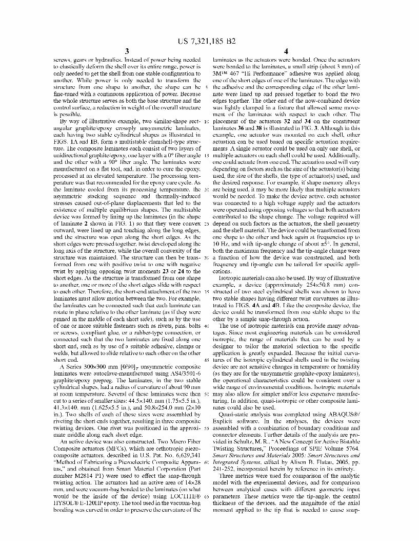
screws, gears or hydraulics. Instead of power being needed laminates as the actuators were bonded. Once the actuators to elastically deform the shell over its entire range, power is were bonded to the laminates, a small strip (about 3 mm) of only needed to get the shell from one stable configuration to 3 W M 467 “Hi Performance” adhesive was applied along another. While power is only needed to transform the one of the short edges of one of the laminates. The edge with structure from one shape to another, the shape can be 5 the adhesive and the corresponding edge of the other lami- fine-tuned with a continuous application of power. Because nate were lined up and pressed together to bond the two the whole structure serves as both the base structure and the edges together. The other end of the now-combined device control surface, a reduction in weight of the overall structure was lightly clamped in a fixture that allowed some move- is possible. ment of the laminates with respect to each other. The
By way of illustrative example, two similar-shape rect- i o placement of the actuators 32 and 34 on the constituent angular graphiteiepoxy crossply unsymmetric laminates, laminates 36 and 38 is illustrated in FIG. 3. Although in this each having two stable cylindrical shapes as illustrated in example, one actuator was mounted on each shell, other FIGS. 1A and lB, form a multistable clamshell-type struc- actuation can be used based on specific actuation require- ture. The composite laminates each consist of two layers of ments. A single actuator could be used on only one shell, or unidirectional graphiteiepoxy, one layer with a 0” fiber angle 15 multiple actuators on each shell could be used. Additionally, and the other with a 90” fiber angle. The laminates were one could actuate from one end. The actuation used will vary manufactured on a flat tool, and, in order to cure the epoxy, depending on factors such as the size of the actuator(s) being processed at an elevated temperature. The processing tem- used, the size of the shells, the type of actuator(s) used, and perature was that recommended for the epoxy cure cycle. As the desired response. For example, if shape memory alloys the laminate cooled from its processing temperature, the 20 are being used, it may be more likely that multiple actuators asymmetric stacking sequence and thermally-induced would be needed. To make the device active, each actuator stresses caused out-of-plane displacements that led to the was connected to a high voltage supply and the actuators existence of multiple equilibrium shapes. The multistable were operated using opposing voltages so that both actuators device was formed by lining up the laminates (in the shape contributed to the shape change. The voltage required will of laminate 2 shown in FIG. 1) so that they were convex 25 depend on such factors as the actuators, the shell geometry outward, were lined up and touching along the long edges, and the shell material. The device could be transformed from and the structure was open along the short edges. As the one shape to the other and back again at frequencies up to short edges were pressed together, twist developed along the 10 Hz, and with tip-angle change of about 25”. In general, long axis of the structure, while the overall convexity of the both the maximum frequency and the tip-angle change were structure was maintained. The structure can then be trans- 30 a function of how the device was constructed, and both formed from one with positive twist to one with negative frequency and tip-angle can be tailored for specific appli- twist by applying opposing twist moments 23 or 24 to the cations. short edges. As the structure is transformed from one shape Isotropic materials can also be used. By way of illustrative to another, one or more of the short edges slide with respect example, a device (approximately 254x502 mm) con- to each other. Therefore, the short-end attachment of the two 35 structed of two steel cylindrical shells was shown to have laminates must allow motion between the two. For example, two stable shapes having different twist curvatures as illus- the laminates can be connected such that each laminate can trated in FIGS. 4A and 4B. Like the composite device, the rotate in plane relative to the other laminate (as if they were device could be transformed from one stable shape to the pinned in the middle of each short side), such as by the use other by a simple snap-through action. of one or more suitable fasteners such as rivets, pins, bolts 40 The use of isotropic materials can provide many advan- or screws, compliant glue, or a rubber-type connection, or tages. Since most engineering materials can be considered connected such that the two laminates are fixed along one isotropic, the range of materials that can be used by a short end, such as by use of a suitable adhesive, clamps or designer to tailor the material selection to the specific welds, but allowed to slide relative to each other on the other application is greatly expanded. Because the initial curva- short end. 45 tures of the isotropic cylindrical shells used in the twisting
A Series 300x300 mm [0/90], unsymmetric composite device are not sensitive changes in temperature or humidity laminates were autoclave-manufactured using AS413501 -6 (as they are for the unsymmetric graphite-epoxy laminates), graphiteiepoxy prepreg. The laminates, in the two stable the operational characteristics could be consistent over a cylindrical shapes, had a radius of curvature of about 90 mm wide range of environmental conditions. Isotropic materials at room temperature. Several of these laminates were then 50 may also allow for simpler and/or less expensive manufac- cut to a series of smaller sizes: 44.5~140. mm (1.75x5.5 in.), turing. In addition, quasi-isotropic or other composite lami- 41.3~140. mm (1.625x5.5 in.), and 50.8x254.0 mm (2x10 nates could also be used. in.). Two shells of each of these sizes were assembled by Quasi-static analysis was completed using ABAQUSBi riveting the short ends together, resulting in three composite Explicit software. In the analyses, the devices were twisting devices. One rivet was positioned in the approxi- 55 assembled with a combination of boundary conditions and mate middle along each short edge. connector elements. Further details of the analysis are pro-
An active device was also constructed. Two Macro Fiber vided in Schultz, M. R., “ANew Concept for Active Bistable Composite actuators (MFCs), which are orthotropic piezo- Twisting Structures,” Proceedings of SPIE Volume 5764, composite actuators, described in U.S. Pat. No. 6,629,341 Smart Structures and Materials 2005: Smart Structures and “Method of Fabricating a Piezoelectric Composite Appara- 60 Integrated Systems, edited by Alison B. Flatau, 2005, pp. tus,” and obtained from Smart Material Corporation (Part 241-252, incorporated herein by reference in its entirety. number M2814 P1) were used to effect the snap-through Three metrics were used for comparison of the analytic twisting action. The actuators had an active area of 14x28 model with the experimental devices, and for comparison mm, and were vacuum-bag bonded to the laminates (on what between analytical cases with different geometric input would be the inside of the device) using LOCTITEB 65 parameters. These metrics were the tip-angle, the central HYSOLB E-120HP epoxy. The tool used in the vacuum-bag thickness of the devices, and the magnitude of the axial bonding was curved in order to preserve the curvature of the moment applied to the tip that is needed to cause snap-
US 7,321,185 B2 5
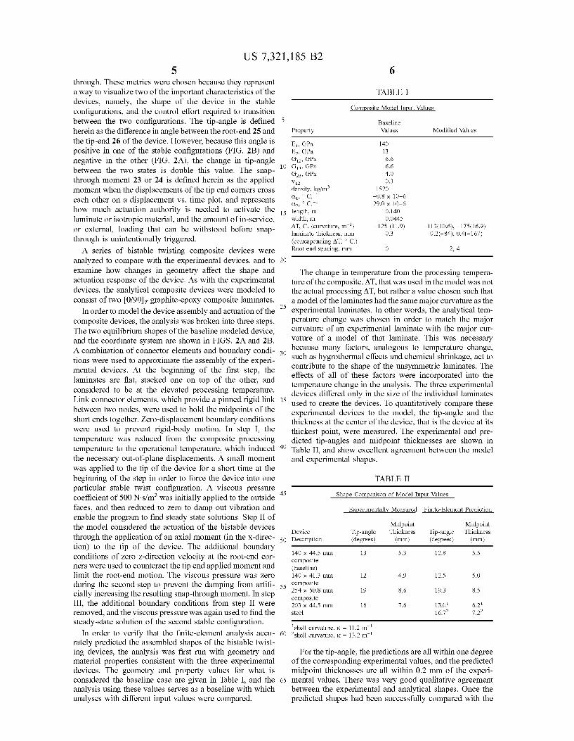
through. These metrics were chosen because they represent a way to visualize two of the important characteristics of the devices, namely, the shape of the device in the stable configurations, and the control effort required to transition between the two configurations. The tip-angle is defined herein as the difference in angle between the root-end 25 and the tip-end 26 of the device. However, because this angle is positive in one of the stable configurations (FIG. 2B) and negative in the other (FIG. 2A), the change in tip-angle between the two states is double this value. The snap- through moment 23 or 24 is defined herein as the applied moment when the displacements of the tip end comers cross each other on a displacement vs. time plot, and represents how much actuation authority is needed to activate the laminate or isotropic material, and the amount of in-service, or external, loading that can be withstood before snap- through is unintentionally triggered.
A series of bistable twisting composite devices were analyzed to compare with the experimental devices, and to examine how changes in geometry affect the shape and actuation response of the device. As with the experimental devices, the analytical composite devices were modeled to consist of two [0/90], graphite-epoxy composite laminates.
In order to model the device assembly and actuation of the composite devices, the analysis was broken into three steps. The two equilibrium shapes of the baseline modeled device, and the coordinate system are shown in FIGS. 2A and 2B. A combination of connector elements and boundary condi- tions were used to approximate the assembly of the experi- mental devices. At the beginning of the first step, the laminates are flat, stacked one on top of the other, and considered to be at the elevated processing temperature. Link connector elements, which provide a pinned rigid link between two nodes, were used to hold the midpoints of the short ends together. Zero-displacement boundary conditions were used to prevent rigid-body motion. In step I, the temperature was reduced from the composite processing temperature to the operational temperature, which induced the necessary out-of-plane displacements. A small moment was applied to the tip of the device for a short time at the beginning of the step in order to force the device into one particular stable twist configuration. A viscous pressure coefficient of 500 N d m 3 was initially applied to the outside faces, and then reduced to zero to damp out vibration and enable the program to find steady state solutions. Step I1 of the model considered the actuation of the bistable devices through the application of an axial moment (in the x-direc- tion) to the tip of the device. The additional boundary conditions of zero z-direction velocity at the root-end cor- ners were used to counteract the tip end applied moment and limit the root-end motion. The viscous pressure was zero during the second step to prevent the damping from artifi- cially increasing the resulting snap-through moment. In step 111, the additional boundary conditions from step I1 were removed, and the viscous pressure was again used to find the steady-state solution of the second stable configuration.
In order to verify that the finite-element analysis accu- rately predicted the assembled shapes of the bistable twist- ing devices, the analysis was first run with geometry and material properties consistent with the three experimental devices. The geometry and property values for what is considered the baseline case are given in Table I, and the analysis using these values serves as a baseline with which analyses with different input values were compared.
6
TABLE I
Composite Model Input Values
Baseline 5
Property Values Modified Values
E,, GPa 140 E,, GPa 13 GI,, GPa 6.6
10 GI,, GPa 6.6 G23, GPa 4.0 V I 2 0.3 density, kg/m3 1520 a', c.-' -0.8 x 10⁻⁶ a,, c.-' 29.0 x 10⁻⁶
width, m 0.0445 AT, C. (curvature, m-') -125 (11.9) -113(10.6), -175(16.9) laminate thickness, mm 0.3 0.2(-84), 0.4(-167) (corresponding AT, ' C.)
15 length, 0.140
Root-end spacing, mm 0 2, 4
20
The change in temperature from the processing tempera- ture of the composite, AT, that was used in the model was not the actual processing AT, but rather a value chosen such that a model of the laminates had the same major curvature as the
25 experimental laminates. In other words, the analytical tem- perature change was chosen in order to match the major curvature of an experimental laminate with the major cur- vature of a model of that laminate. This was necessary because many factors, analogous to temperature change,
30 such as hygrothermal effects and chemical shrinkage, act to contribute to the shape of the unsymmetric laminates. The effects of all of these factors were incorporated into the temperature change in the analysis. The three experimental devices differed only in the size of the individual laminates
35 used to create the devices. To quantitatively compare these experimental devices to the model, the tip-angle and the thickness at the center of the device, that is the device at its thickest point, were measured. The experimental and pre- dicted tip-angles and midpoint thicknesses are shown in
40 Table 11, and show excellent agreement between the model and experimental shapes.
TABLE I1
45 Shape Comparison of Model Input Values
Experimentally Measured Finite-Element Prediction
Midpoint Midpoint Device Tip-angle Thickness Tip-angle Thickness
50 Description (degrees) (mm) (degrees) (mm)
140 x 44.5 mm 13 5.3 12.8 5.5 composite (baseline) 140 x 41.3 mm 12 4.9 12.5 5.0
55 composite 254 x 50.8 mm 19 8.6 19.3 8.5 composite 203 x 44.5 mm 16 7.6 13.0' 6.2' steel 16.7, 7.2,
'shell curnature, K = 11.2 m-' 60 'shell curnature. K = 13.2 m-'
For the tip-angle, the predictions are all within one degree of the corresponding experimental values, and the predicted midpoint thicknesses are all within 0.2 mm of the experi-
65 mental values. There was very good qualitative agreement between the experimental and analytical shapes. Once the predicted shapes had been successfully compared with the
US 7,321,185 B2 7
experimental devices, the analysis was next used to predict how changes in some of the geometric parameters would change the shape and behavior of these devices.
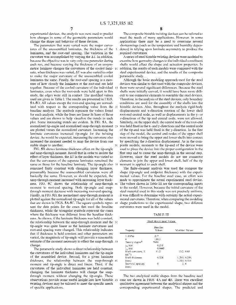
The parameters that were varied were the major curva- tures of the unassembled laminates, the thickness of the laminates, and the root-end spacing. The variation in the curvature was accomplished by varying the AT. In addition, because the objective was to vary only one parameter during each run, and because varying the thickness of an unsym- metric laminate changes the curvatures of the cooled lami- nate, when thickness was varied, AT was also varied in order to make the major curvature of the unassembled cooled laminates the same. Finally, the root-end spacing is a mea- sure of how closely the laminates at the root-end are held together. Because of the cooled curvature of the individual laminates, even when the root-ends were held apart in this study, the edges were still in contact. The modified values used are given in Table I. The results are presented in FIGS. 5A-5D. All values except the root-end spacing are normal- ized with respect to the corresponding value from the baseline analysis. The symbols represent the values found for each analysis, while the lines are linear fit lines of those values and are shown to help visualize the trends in each plot. Some interesting trends are evident. In FIG. 5A, the normalized tip-angle and normalized snap-through moment are plotted verses the normalized curvature. Increasing the laminate curvatures increased tip-angle for the twisting device. As would be expected, increasing the curvature also increased the moment needed to snap the device from one stable shape to another.
FIG. 5B shows laminate thickness effect on the tip-angle and snap-through moment. Recall that in order to isolate the effect of layer thickness, the AT in the models was varied so that the curvatures of the separate laminates remained the same as those for the baseline laminate. The tip-angle also remained fairly constant with changing layer thickness, presumably because the unassembled curvatures were all basically the same. However, as should be expected, the snap-through moment increased with increasing layer thick- ness. FIG. 5C shows the relationship of snap-through moment to root-end spacing. Both tip-angle and snap- through moment decrease with increasing root-end spacing. Finally, in FIG. 5D, the normalized snap-through moment is plotted against the normalized tip-angle for all of the values that are shown in FIGS. 5A-5C. The square symbols repre- sent the data points for the cases that used the baseline thickness, while the triangular symbols represent the cases where the thickness was different from the baseline thick- ness. As shown, if the laminate thickness was held constant, the relationship between the snap-through moment and the tip-angle was quite linear as the laminate curvatures and root-end spacing were changed. This relationship indicates that if thickness is held constant and other parameters are varied, the magnitude of tip-angle will provide a reasonable estimate of the moment necessary to effect the snap-through change.
The parametric study shows a direct relationship between the curvatures of the individual laminates and the tip-angle of the assembled device. Second, for a given laminate thickness, the relationship between the snap-through moment and tip-angle is direct and linear. Third, if the curvatures of the individual laminates are held constant, changing the laminate thickness will change the snap- through moment without changing the tip-angle. These observations provide some useful insight into how bistable twisting devices may be tailored to meet the specific needs of specific applications.
8 The composite bistable twisting devices can be tailored to
meet the needs of many applications. However, in some applications there may be a need to overcome several shortcomings (such as the temperature and humidity depen-
5 dence) in relying upon laminate asymmetry to produce the required curvatures.
A series of steel bistable twisting devices were modeled to examine how geometry changes to the individual constituent shells would affect the shape and actuation properties. In
i o addition, the results of such models were compared with the steel experimental device, and the results of the composite parametric study.
Although the basic modeling approach used for the steel devices was similar to that used with the composite devices,
15 there were several significant differences. Because the steel shells were initially curved, it would have been more diffi- cult to use connector elements to assemble the steel devices. Therefore, in the analysis of the steel devices, only boundary conditions are used for the assembly of the shells into the
20 bistable devices. Also, throughout the analysis rigid-body displacements and x-direction rotation of the lower shell root-end central node, as well as displacements in the y- or z-directions of the tip end central node, were not allowed. Similarly, on the upper shell, the central node of the root-end
25 was held fixed in the x- and y-directions and the central node of the tip-end was held fixed in the y-direction. In the first step of the model, the central end nodes of the upper shell were moved to bring the upper and lower shells into contact by specifying the z-direction displacement. As in the com-
30 posite models, moments to the tip-end of the device were used to place the device into the proper configuration in the first step and to cause the snap-through in the second step. However, since the steel models do not use connector elements to join the upper and lower shell, half of the tip
The finite-element analysis was used the compare the shape (tip-angle and midpoint thickness) with the experi- mental values. For the baseline steel case, an effort was made to approximate the actual experimental steel device.
40 The values shown in Table I11 are the corresponding inputs to the model. However, because the initial curvature of the steel material used in this study was not precisely uniform, it was difficult to determine with certainty the actual experi- mental curvatures. Therefore, when comparing the modeling
45 shape predictions to the experimental shape, two different curvatures were used in the model.
TABLE I11
35 moment is applied to each shell.
Steel Model Input Values 50
Baseline Property Values Modified Values
E (GPa)
55 Density (kg/m3’ Y
L, (m) L, (m)
(m-’)
60 (m)
(m)
Shell curvature, K
Shell thickness
Root-end spacing
207 130.3
7850 0.203 0.0445
11.2 13.2, 9.85
0.324 0.200, 0.250, 0.350, 0.400
0 2. 4
The two analytical stable shapes from the baseline steel 65 case are shown in FIGS. 4A and 4B. There was excellent
qualitative agreement between the analytical shapes and the corresponding experimental shapes. The predicted and
US 7,321,185 B2 9 10
actual tip-angles and midpoint thicknesses are shown in 5B). Unfortunately, for the steel devices, the relationship is Table 11, and show fairly good agreement. The actual tip- not as simple (FIG. 6B). When FIGS. 5A and 5C are angle was within the two predicted tip-angles. In contrast, compared with FIGS. 6A and 6C, it is apparent that the the actual midpoint thickness is outside the predicted range. changes in the curvature and the root-end spacing affect the However, because low-grade steel was used in the experi- 5 composite devices and the steel devices in similar ways. In mental device, some plastic deformation occurred during particular, the tip-angle and snap-through moment increase assembly of the device. This plastic deformation was not with increasing shell curvature, and decrease with increasing accounted for in the models and may be responsible for root-end spacing. This last effect, dealing with the root-end some of the difference that is seen. spacing, could prove very useful in service. All of the
As with the composite modeling, a parametric study was i o parameter changes (curvature and thickness) except the done with steel devices to determine how modifying some of root-end spacing are fixed when the device is constructed, so the input values would affect the tip-angle and snap-through they cannot be used to vary the stable configurations or the moment of the devices. The same three geometric param- response of a single device. However, a method of varying eters were varied: the curvature of the individual cylindrical the root-end spacing could be implemented in a design shells, the thickness of the shells, and the root-end spacing. 15 where these devices would be used. This would allow one to However, these parameters were all independent for the steel make use of the advantages of the multistable device, yet devices. The modified values that were used in this para- still allow for a continuous variation in the shape of that metric study are shown in Table 111, and results from the device. study are presented in FIGS. 6A-6D, where all values except The advantages of the present invention are numerous. the root-end spacing are normalized by the steel baseline 20 Statically stable shapes are the operational shapes, and values. As with FIGS. 5A-5D, the symbols represent the power to the actuation systems is only required when values found from the individual runs of the analysis, and, transforming the device from one shape to another. How- where the trend was consistent, a linear-fit line is included as ever, there are many other advantages to this type of a way to help visualize the trend. As shown in FIG. 6A, structure: the idea and design are mechanically simple, and increasing the curvature, Le., decreasing the radius of cur- 25 large shape change can be accomplished without compli- vature, of the uncombined cylindrical shells linearly cated actuator systems such as screws, gears, or hydraulics. increased the tip-angle and the snap-through moment. The In addition, there is a large change in shape with small effects of changing the shell thickness on the tip-angle and energy input, and power is only needed to transform the snap-through moment are shown in FIG. 6B. The tip-angle structure from one shape to another. The shape can be fine decreased fairly linearly with increasing thickness. How- 30 tuned with a continuous application of power, or a change in ever, the relationship between snap-through moment and the root-end spacing. thickness did not show a consistent trend. Instead, the Devices such as this could find use in many applications, snap-through moment initially increased with increasing the most obvious being aerodynamic applications such as for thickness, but then decreased as the thickness continued to morphing wings or rotor blades, or for trailing-edge control increase. It appeared that the snap-through moment had a 35 surfaces for the same. Because the structure can serve as maximum near the baseline thickness. In FIG. 6C, it is both the base structure and the control surface, there can be apparent that both the normalized tip-angle and normalized a reduction in overall system weight, which is an important snap-through moment decreased with increasing root-end consideration in aerodynamic applications. These devices spacing. Finally, in FIG. 6D, the normalized snap-through could also be used near the hub on a rotor blade to change moment is plotted against the normalized tip-angle for all of 40 the angle of attack of the entire blade, or in a fan where it the steel cases. The square symbols represent all of the cases is desirable to change the direction of airflow without that used the baseline thickness, and the triangles represent changing the direction of rotation of the shaft. The devices the cases with other than the baseline thickness. When the could be used in airflow controllers for vortex generation thickness was held constant, the relationship between snap- over an airfoil or in an intake manifold for an engine, through moment and tip-angle was fairly linear with increas- 45 autotwist blades or louvers, amplified motion structure for ing tip-angle leading to increased snap-through moment. peizoelectric sensingivoltage generation, or even a child’s However, there was not a clear relationship between the plaything. snap-though moment and the tip-angle if the shell thick- Although the invention has been described relative to nesses were changed. specific embodiments thereof, there are numerous variations
A comparison of FIGS. 5 and 6 shows many similarities 50 and modifications that will be readily apparent to those between the effect of geometric parameter changes on the skilled in the art in light of the above teachings. For composite and steel devices, and allows more observations example, although the illustrative embodiments consisted of to be made about the shape and performance of the bistable sharp leading and trailing edges, an insert could be used to twisting devices. Looking first at FIGS. 5D and 6D, the create a more blunt leading edge like most common airfoils. tip-angle is a fairly good indicator of the snap-through 55 Also, the structure could be encapsulated in a flexible elastic moment, provided the thickness is not varied. Because the sheet if it were necessary to prevent the sliding surfaces from device with the greater tip-angle would need to be deformed separating. The idea could also be scaled up or down, and more in order to effect the snap-through, changing a param- different materials could be used. eter to increase the tip-angle would tend to increase snap- through moment. However, because the relationship is fairly 60 linear, it should be easier to tailor the behavior of such devices. If it is desired to change the snap-through moment without changing the tip-angle, the shell thickness can be changed. For the composite devices, if the unassembled shell curvatures were held fixed as the laminate thickness 65 was changed, tip-angle remained constant, and the snap- through moment changed in a basically linear way (FIG.
The invention claimed is: 1. A multistable device, comprising: two similar-shape shells, each having a cylindrical shape; said shells each having a first and second set of opposing
edges; said first set of opposing edges aligned such that they
touch along the length thereof; said second set of opposing edges connected such that
some portion thereof may move relative to one another;
US 7,321,185 B2 11
a means to effect transformation of said device from a first
2. The device of claim 1, wherein said multistable device comprises at least two stable shapes having a difference in axial twist.
3. The device of claim 1, wherein said shells are aligned such that each is convex outward.
4. The device of claim 1, wherein said shells are aniso- tropic.
5. The device of claim 1, wherein said shells are lami- nates.
6. The device of claim 5, wherein said laminates are unsymmetric.
7. The device of claim 5, wherein said laminates are cross-ply.
8. The device of claim 5, wherein each said laminate comprises two layers of unidirectional graphiteiepoxy, one layer having a 0" fiber angle and one layer having a 90" fiber angle.
9. The device of claim 5, wherein said cylindrical shape is induced by asymmetric stacking sequence and thermally induced stresses.
10. The device of claim 1, wherein said shells are isotro- pic.
11. The device of claim 10, wherein said shells are steel. 12. The device of claim 2, wherein said two stable shapes
are a positive twist curvature and a negative twist curvature. 13. The device of claim 1, wherein said second set of
opposing edges are connected such that each shell may rotate in plane relative to the other shell.
14. The device of claim 1, wherein said second set of opposing edges are connected such that the two shells are fixed on one end but may slide relative to one another on the other end.
15. The device of claim 13, wherein said second set of opposing edges comprises a means for fixing the approxi- mate middle of each said edge.
stable shape to at least a second stable shape.
12 16. The device of claim 14, wherein said fixed end
comprises a means for fixing the entire length thereof. 17. The device of claim 15, wherein said means for fixing
is selected from the group consisting of rivet, pin, bolt,
18. The device of claim 16, wherein said means for fixing is selected from the group consisting of adhesive, clamp and weld.
19. The device of claim 1, wherein said means to effect 10 transformation is one or more actuators fixed on at least one
said shell. 20. The device of claim 1, wherein said means to effect
transformation is one or more actuators fixed on at least one end of said shells.
21. The device of claim 19, wherein said one or more actuators is selected from the group consisting of piezoelec- tric, shape memory alloy, magnetostrictive, ferroelectric, shape memory polymer and electroactive polymer.
22. The device of claim 20, wherein said one or more 2o actuators is selected from the group consisting of piezoelec-
tric, shape memory alloy, magnetostrictive, ferroelectric, shape memory polymer and electroactive polymer.
23. The device of claim 21, wherein said piezoelectric actuator is selected from the group consisting of piezocer- amic, piezocomposite and piezopolymer.
24. The device of claim 22, wherein said piezoelectric actuator is selected from the group consisting of piezocer- amic, piezocomposite and piezopolymer.
25. The device of claim 1, wherein said means to effect transformation is hydraulic or motor.
26. The device of claim 1, wherein said shells are rect- angular.
27. The device of claim 1, further comprising means to 35 vary the spacing between said second set of opposing edges.
5 screw, and compliant adhesive.
l5
25
3o
* * * * *


![United States Patent 4,640,331 - Microsoft States Patent [19J Braun et al. [54] CENTRAL TIRE INFLATION SYSTEM [75] Inventors: Eugene R. Braun, Royal Oak; Gary R. Schultz, Novi, both](https://img.pdfslide.us/doc/110x75/5ab7fc197f8b9ac60e8c453b/united-states-patent-4640331-microsoft-states-patent-19j-braun-et-al-54.jpg)